product report: keene's new ÒultraÓ dredge models offer
TRANSCRIPT
There is an old axiom known to golddredgers, being that big dredges do bigwork and give you big results and smalldredges well, you get the picture. And itseems that this perception by manygold miners has always been assumedto be true.
But with Keene's new “Ultra” line ofthree and four inch suction golddredges, this old theory can now beentossed out the window. The fact is thatthese new model gold dredges fromKeene Engineering perform much likethe larger Keene units and they areopening up new and more remote areasto productive gold dredging, includingmany streams that have never beforebeen dredged.
Now that's exciting news. I know this firsthand because this is
exactly what happened to me last sum-mer while dredging in a remote gold-bearing creek located in the higher ele-
vations within a well known area ofsouthwest Oregon's mountain wilder-ness.
Now here's the story behind myadventure.
What has now became the Keene“Ultra” series of dredges began somemonths ago in a discussion I had withJerry, Pat and Mark Keene. We hadbeen talking about a need for designingand developing new, lighter-weightKeene dredge models capable of beingtransported and operated in extremelyremote, upper elevation areas oftenoverlooked by today's gold miners. Theconcept was really quite simple, put bigdredge performance into a small andhighly portable package.
And small means that it had to fit intothe back of a mini-truck or inside a smallSUV.
So we'll begin with a fact. It is truethat many of today's gold dredgers are
aware that a lot of gold remains to bediscovered in the hundreds ofstreambeds in remote and distant upperelevation rivers and creeks but the over-whelming challenge for dredgers is get-ting up and into these sites, especiallywith portable equipment that can do areasonable job.
Years back I had told Mark and PatKeene about a remote Oregon creek Ihad worked back in the 1980s which wediscovered had good quantities of bothfine and course gold. In the distantpast and through the region's geologicalevolution, this stream had eroded a newchannel directly across an ancient ter-tiary riverbed where ample amounts ofgold once had resided. Some of thatgold had been re-deposited in this newcreek bed, and from what we saw in oursampling, the composition of the over-burden indicated that no one had everdredged on this location.
But here was the problem. Gettingup to this creek was a major chal-lenge because it's located in an espe-cially remote and rugged mountainousupper elevation region with no nearbyroads or trails for packing in our equip-ment. Getting up to this site requiresseveral difficult hikes on terrain moresuited for pack animals or mountaingoats.
And large productive equipment ofthat time was just not light enough to befeasibly transported up to this creek.Back then we had successfully used atiny backpack rig but the amount ofrecovery was not really worth the effort.
So Keene Engineering began workon designing what they now call the“Ultra” series of gold dredges. And lastsummer I gave one of their new modelsa test on this remote location.
It began with this new Keene dredgesitting in parts and pieces on my shopfloor. Starting with the basic frame andfloatation, in just ten minutes it wascompletely assembled. I was
37
Product Report:Keene's New “Ultra” DredgeModels Offer Exciting New Gold
Recovery Opportunities. By David Knowlen
impressed as easy and smooth theassembly went.
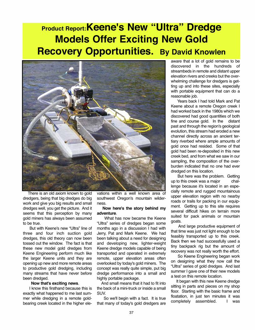
I also noticed that it looked similar tomy five-inch Keene dredge, large in fea-tures but so much smaller in size andweight being just over forty-one incheswide and about six feet long, perfect fora small mini-truck or SUV. And it waspowered with a reliable Honda 4horsepower engine, a proven high-out-put (HO) Keene pump and connected toa T80 compressor for underwateroperations.
Best of all, the sluice box had all ofKeene's unique combination ofHungarian riffles, a large upper area ofblack rubber matting for checking val-ues and a generous section of miner'smoss used for trapping fine gold. Allassembled on the light frame and twopontoons with the hoses, jet flare andKeene's great non-clogging couplersystem it was noticeably lightweight.
And while my wife said it was cute,cute doesn't mean it will bring in thegold. The proof would be how it deliv-ered in productivity and recovery.
So just a week later and a half-day'sdrive culminating at the end of anancient logging road our travels hadbrought us within about a mile of thisremote Oregon creek. I noticed thattwenty years had not changed this areatoo much.
Jim, my dredging partner and Isecured my truck in a clearing under alarge oak tree and we unloaded thedredge components along with myother mining and camping gear. Thehardest part lay ahead, packing in all thegear on a narrow and winding uphill trail.The plan was simple, we would arrangeall of our gear into several moderatepack loads with as much as we couldphysically carry on each trip up and ontothe site. The remainder of our gearwould be kept here in our base camp. The next day we were up early and Iquickly noticed that Keene's newdredge component design made theunit weight much lighter and easier forus to carry. The most challenging singlecomponent was the engine, pump andcompressor which we put on a custom-built hand (Page Two)-truck with large wheels. While it tookthe better part of a day we packed in all
o four
operational “necessities” and by lateafternoon our dredge was assembledand in the creek ready for its first trialearly the next day.
Now something you should know isthat I am now in my early sixties and amuch younger man would have a wholelot less challenge in toting a golddredge, support equipment and camp-ing gear all the way up to a site such asthis one. But I also believe that myenthusiasm for dredging and a long andrecurring case of 'gold fever' all added tomy stamina.
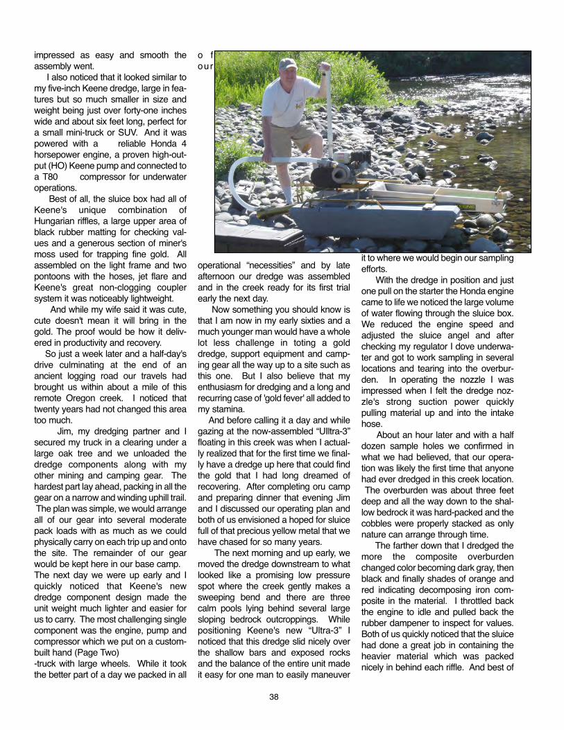
And before calling it a day and whilegazing at the now-assembled “UIltra-3”floating in this creek was when I actual-ly realized that for the first time we final-ly have a dredge up here that could findthe gold that I had long dreamed ofrecovering. After completing oru campand preparing dinner that evening Jimand I discussed our operating plan andboth of us envisioned a hoped for sluicefull of that precious yellow metal that wehave chased for so many years.
The next morning and up early, wemoved the dredge downstream to whatlooked like a promising low pressurespot where the creek gently makes asweeping bend and there are threecalm pools lying behind several largesloping bedrock outcroppings. Whilepositioning Keene's new “Ultra-3” Inoticed that this dredge slid nicely overthe shallow bars and exposed rocksand the balance of the entire unit madeit easy for one man to easily maneuver
it to where we would begin our samplingefforts.
With the dredge in position and justone pull on the starter the Honda enginecame to life we noticed the large volumeof water flowing through the sluice box.We reduced the engine speed andadjusted the sluice angel and afterchecking my regulator I dove underwa-ter and got to work sampling in severallocations and tearing into the overbur-den. In operating the nozzle I wasimpressed when I felt the dredge noz-zle's strong suction power quicklypulling material up and into the intakehose.
About an hour later and with a halfdozen sample holes we confirmed inwhat we had believed, that our opera-tion was likely the first time that anyonehad ever dredged in this creek location.The overburden was about three feet
deep and all the way down to the shal-low bedrock it was hard-packed and thecobbles were properly stacked as onlynature can arrange through time.
The farther down that I dredged themore the composite overburdenchanged color becoming dark gray, thenblack and finally shades of orange andred indicating decomposing iron com-posite in the material. I throttled backthe engine to idle and pulled back therubber dampener to inspect for values.Both of us quickly noticed that the sluicehad done a great job in containing theheavier material which was packednicely in behind each riffle. And best of
38
3939
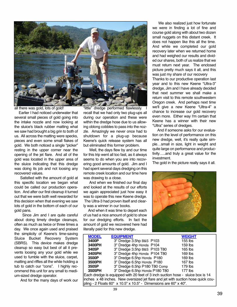
all there was gold, lots of gold!Earlier I had noticed underwater that
several small pieces of gold going intothe intake nozzle and now looking atthe sluice's black rubber matting whatwe saw had brought a big grin to both ofus. All across the matting were specks,pieces and even some small flakes ofgold. We both noticed a single “picker”resting in the upper corner near theopening of the jet flare. And all of thegold was located in the upper area ofthe sluice indicating that this dredgewas doing its job and not loosing anyrecovered values.
Satisfied with the amount of gold atthis specific location we began whatcould be called our production opera-tion. And after our first cleanup it turnedout that we were both well rewarded forthis decision when that evening we sawlots of gold in the bottom of each of ourgold pans.
Since Jim and I are quite carefulabout doing timely dredge cleanups,often as much as twice or three times aday. We once again used and praisedthe simplicity of Keene's time-savingSluice Bucket Recovery System(SBRS). This device makes dredgecleanup so easy but best of all it pre-vents loosing any your gold while weused to fumble with the sluice, carpet,matting and riffles all the while holding atub to catch our “cons”. I highly rec-ommend this unit for any small to medi-um-sized dredge operator.
And for the many days of work our
“little” dredge performed flawlessly. Irecall that we had only two plug-ups allduring our operation and these werewithin the dredge hose due to us allow-ing oblong cobbles to pass into the noz-zle. Amazingly we never once had toshutdown for a plug-up becauseKeene's quick release system has allbut eliminated this former problem.
Well, the days flew by and our timefor this trip went all too fast, as it alwaysseems to do when you are into recov-ering good amounts of gold. Jim and Ihad spent several days dredging on thisremote creek location and our time herewas drawing to a close.
And when we finished our final dayand looked at the results of our effortswe again appreciated just how easy itwas to operate this new Keene dredge.The Ultra-3 had proven itself and clear-ly was a winner in our books.
And when it was time to depart eachof us had a nice amount of gold to showfor our dredging efforts. In fact theamount of gold we recovered here hadliterally paid for this new dredge.
We also realized just how fortunatewe were in finding a lot of fine andcourse gold along with about two dozensmall nuggets on this distant creek. Itdoes not happen like this all the time.And while we completed our goldrecovery later when we returned homeand had weighed our results and divid-ed our shares, both of us realize that wemust return next year. The enclosedpicture pretty much says it all, and thiswas just my share of our recoveryThanks to our productive operation lastyear and to this new Keene “Ultra-3”dredge, Jim and I have already decidedthat next summer we shall make areturn visit to this remote southwesternOregon creek. And perhaps next timewe'll give a new Keene “Ultra-4” achance to increase our gold recoveryeven more. Either way I'm certain thatKeene has a winner with their new“Ultra” series of dredges.
And if someone asks for our evalua-tion on the level of performance on thisnew dredge, well, it's really quite sim-ple…small in size, light in weight andquite large on performance and produc-tivity…..and truly a great value for theinvestment. The gold in the picture really says it all.
MODEL EQUIPMENT WEIGHT3400P 3" Dredge 3.5hp B&S P103 155 lbs 3400PH 3" Dredge 4hp Honda P104 159 lbs 3405P 3" Dredge 3.5hp B&S P103 T80 165 lbs 3405PH 3" Dredge 4hp Honda P104 T80 169 lbs3500P 3" Dredge 6.5hp Honda P180 169 lbs 3500PH 3" Dredge 6.5hp Honda P180 167 lbs3505P 3" Dredge 6.5hp P180 T80 Comp 179 lbs3505PH 3" Dredge 6.5hp Honda P180 T80 177 lbs
Each dredge is equipped with 20 feet of 3 inch suction hose - sluice box is 14inches x 48 inches. New oversized jet flare and jet with suction hose quick cou-pling - 2 Floats 60“ x 10.5" x 10.5" - Dimensions are 60" x 40".
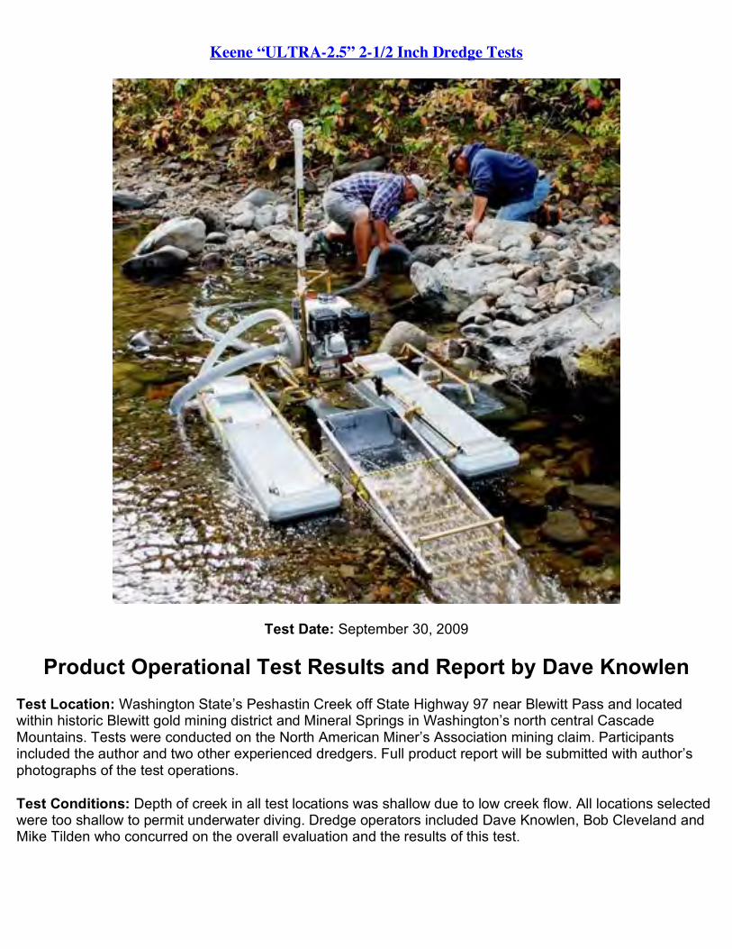
Keene “ULTRA-2.5” 2-1/2 Inch Dredge Tests
Test Date: September 30, 2009
Product Operational Test Results and Report by Dave Knowlen Test Location: Washington State’s Peshastin Creek off State Highway 97 near Blewitt Pass and located within historic Blewitt gold mining district and Mineral Springs in Washington’s north central Cascade Mountains. Tests were conducted on the North American Miner’s Association mining claim. Participants included the author and two other experienced dredgers. Full product report will be submitted with author’s photographs of the test operations.
Test Conditions: Depth of creek in all test locations was shallow due to low creek flow. All locations selected were too shallow to permit underwater diving. Dredge operators included Dave Knowlen, Bob Cleveland and Mike Tilden who concurred on the overall evaluation and the results of this test.

General Test Description and Results: Dredge was operated in different creek locations and in varying depths of water and volume/rate of flow. Standard Keene intake nozzle was used. Settings of sluice varied from four inches to twenty inches from upper stop. Optimum sluice settings appeared to be at approx. 12-14 inches downward with engine throttle operating at 60-70%.
New dredge sluice size was 12 inch in width and 40 inches in length. This configuration functioned very well with excellent gold recovery and retention with majority (over 90%) of fine gold, flakes and small nuggets located on Keene’s new riffle rubber matting. Some small modifications were made prior to the tests including trimming to the rubber mat plate to improve sluice disassembly for ease of dredge clean-up. A .180 inch shim was installed under the joggled aluminum mat retainer in the upper jet flare to permit easier assembly.
Engine/pump during tests was operated from idle to full throttle and we strived in all set-ups for determining an optimum speed for water volume, suction and flow to compliment the sluice angle settings to allow maximum recovery. Pump performed exceptionally well and nozzle suction was noted as strong and consistent throughout all power ranges and settings. Pump provided excellent volume for this sluice size. No loading of the sluice box with rocks/cobbles was noted and sluice cleaned itself well even at lower engine settings. Only one mid-hose plug-up was encountered
Overal Observations/Recommendations:
1. Dredge sluice size (40” X 12”) is excellent for this setup and riffle placement is good. This design needs no additional modifications or configuration changes.
2. Operators noted no problem with the existing floatation which is generally adequate for the overall dredge weight even under considerable loading conditions.
3. New rubber matting did retain virtually all recovered gold (approx. 95%) below and within the formed rubber riffles. We had to remove the larger pieces of gold with a tweezers or sweep the mat with a utility brush to remove the fine gold as the matting provides strong adhesion to retain the values.
4. While the altered sluice design was used with a stock 2-1/2 inch jet flare it appears the dredge might perform more effectively with a wider 12 inch wide jet flare over the supplied ten inch unit which will make the removal of the rubber matting/plate easier for the operator during dredge cleanup.
5. In an earlier test this unit was operated with a smaller Honda 2.5 hp engine and P-95 pump and we noted the water volume appeared to be inadequate for this new and larger sluice size; however the smaller Honda engine works well with the current 10 inch sluice.
6. We highly recommend that Keene design and manufacture a 2.5 inch swivel nozzle to compliment this new dredge model which will improve operation
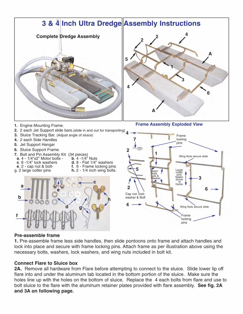
3 & 4 Inch Ultra Dredge Assembly Instructions
22
1
6
3
4
4
5
A
A
Complete Dredge Assembly
Frame Assembly Exploded View
21
3
4
4
5
6
7
2
MotorBoltsnuts &Washer
Framelockingpins
Framelockingpins
Largecotter pins
fastensluice
toframe
Cap nut, lock-washer & Bolt
Wing Nuts secure slide
Wing Nuts secure slide
1. Engine Mounting Frame.2. 2 each Jet Support slide bars.(slide in and out for transporting)3. Sluice Tracking Bar. (Adjust angle of sluice)4. 2 each Side Handles 5. Jet Support Hangar6. Sluice Support Frame.7. Bolt and Pin Assembly Kit (34 pieces)
a. 4 - 1/4“x2” Motor bolts - b. 4 -1/4” Nuts c. 6 -1/4” lock washers d. 8 - Flat 1/4” washers e. 2 - cap nut & bolt- f. 6 - Frame locking pins
g. 2 large cotter pins h. 2 - 1/4 inch wing bolts.
Pre-assemble frame1. Pre-assemble frame less side handles, then slide pontoons onto frame and attach handles and lock into place and secure with frame locking pins. Attach frame as per illustration above using thenecessary bolts, washers, lock washers, and wing nuts included in bolt kit.
Connect Flare to Sluice box2A. Remove all hardware from Flare before attempting to connect to the sluice. Slide lower lip offflare into and under the aluminum tab located in the bottom portion of the sluice. Make sure theholes line up with the holes on the bottom of sluice. Replace the 4 each bolts from flare and use tobolt sluice to the flare with the aluminum retainer plates provided with flare assembly. See fig. 2Aand 3A on following page.
h
c
g
a
b
f
d
e
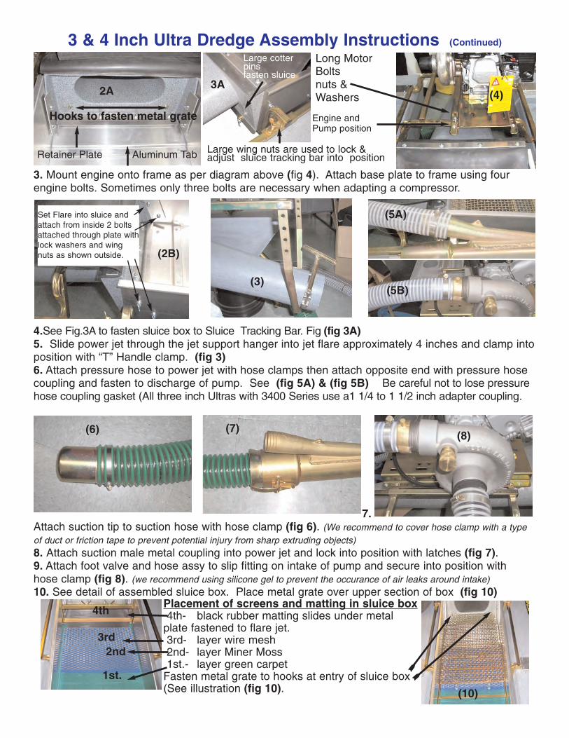
3 & 4 Inch Ultra Dredge Assembly Instructions (Continued)
4.See Fig.3A to fasten sluice box to Sluice Tracking Bar. Fig (fig 3A)5. Slide power jet through the jet support hanger into jet flare approximately 4 inches and clamp intoposition with “T” Handle clamp. (fig 3)6. Attach pressure hose to power jet with hose clamps then attach opposite end with pressure hosecoupling and fasten to discharge of pump. See (fig 5A) & (fig 5B) Be careful not to lose pressurehose coupling gasket (All three inch Ultras with 3400 Series use a1 1/4 to 1 1/2 inch adapter coupling.
7.Attach suction tip to suction hose with hose clamp (fig 6). (We recommend to cover hose clamp with a typeof duct or friction tape to prevent potential injury from sharp extruding objects) 8. Attach suction male metal coupling into power jet and lock into position with latches (fig 7). 9. Attach foot valve and hose assy to slip fitting on intake of pump and secure into position withhose clamp (fig 8). (we recommend using silicone gel to prevent the occurance of air leaks around intake)10. See detail of assembled sluice box. Place metal grate over upper section of box (fig 10)
Set Flare into sluice andattach from inside 2 boltsattached through plate withlock washers and wingnuts as shown outside. (2B)
(3)(5B)
(5A)
3. Mount engine onto frame as per diagram above (fig 4). Attach base plate to frame using fourengine bolts. Sometimes only three bolts are necessary when adapting a compressor.
(6) (8)
Placement of screens and matting in sluice box4th- black rubber matting slides under metal
plate fastened to flare jet.3rd- layer wire mesh2nd- layer Miner Moss1st.- layer green carpet
Fasten metal grate to hooks at entry of sluice box(See illustration (fig 10).
(7)
Retainer Plate Aluminum Tab
2A
Long MotorBoltsnuts &Washers
Engine and Pump position
3A
Large wing nuts are used to lock &adjust sluice tracking bar into position
Large cotter pins fasten sluice
(4)
1st.
2nd3rd
4th
Hooks to fasten metal grate
(10)
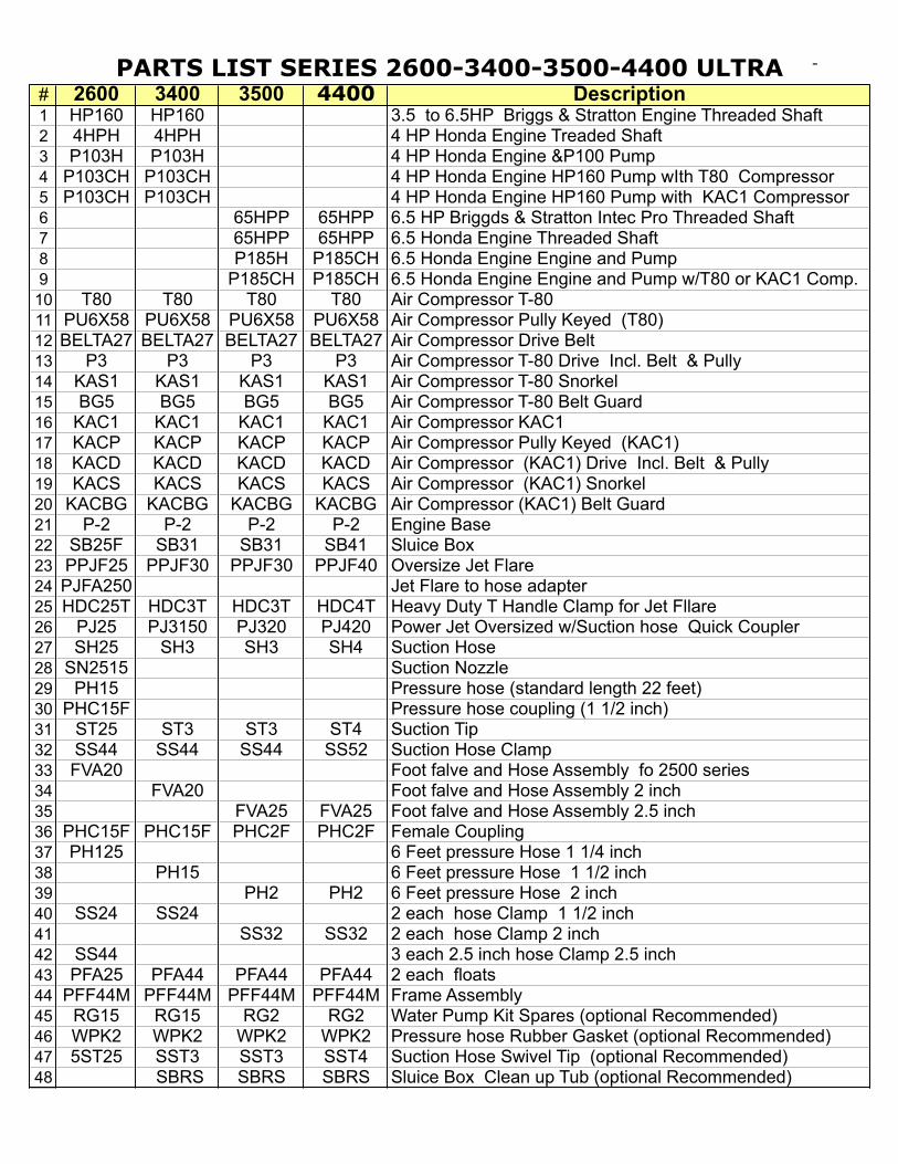
PARTS LIST SERIES 2600-3400-3500-4400 ULTRA DREDGES
-
# 2600 3400 3500 4400 Description1 HP160 HP160 3.5 to 6.5HP Briggs & Stratton Engine Threaded Shaft2 4HPH 4HPH 4 HP Honda Engine Treaded Shaft3 P103H P103H 4 HP Honda Engine &P100 Pump4 P103CH P103CH 4 HP Honda Engine HP160 Pump wIth T80 Compressor5 P103CH P103CH 4 HP Honda Engine HP160 Pump with KAC1 Compressor6 65HPP 65HPP 6.5 HP Briggds & Stratton Intec Pro Threaded Shaft7 65HPP 65HPP 6.5 Honda Engine Threaded Shaft8 P185H P185CH 6.5 Honda Engine Engine and Pump9 P185CH P185CH 6.5 Honda Engine Engine and Pump w/T80 or KAC1 Comp.
10 T80 T80 T80 T80 Air Compressor T-8011 PU6X58 PU6X58 PU6X58 PU6X58 Air Compressor Pully Keyed (T80)12 BELTA27 BELTA27 BELTA27 BELTA27 Air Compressor Drive Belt 13 P3 P3 P3 P3 Air Compressor T-80 Drive Incl. Belt & Pully14 KAS1 KAS1 KAS1 KAS1 Air Compressor T-80 Snorkel15 BG5 BG5 BG5 BG5 Air Compressor T-80 Belt Guard16 KAC1 KAC1 KAC1 KAC1 Air Compressor KAC117 KACP KACP KACP KACP Air Compressor Pully Keyed (KAC1)18 KACD KACD KACD KACD Air Compressor (KAC1) Drive Incl. Belt & Pully19 KACS KACS KACS KACS Air Compressor (KAC1) Snorkel20 KACBG KACBG KACBG KACBG Air Compressor (KAC1) Belt Guard21 P-2 P-2 P-2 P-2 Engine Base22 SB25F SB31 SB31 SB41 Sluice Box 23 PPJF25 PPJF30 PPJF30 PPJF40 Oversize Jet Flare24 PJFA250 Jet Flare to hose adapter25 HDC25T HDC3T HDC3T HDC4T Heavy Duty T Handle Clamp for Jet Fllare26 PJ25 PJ3150 PJ320 PJ420 Power Jet Oversized w/Suction hose Quick Coupler27 SH25 SH3 SH3 SH4 Suction Hose28 SN2515 Suction Nozzle29 PH15 Pressure hose (standard length 22 feet)30 PHC15F Pressure hose coupling (1 1/2 inch)31 ST25 ST3 ST3 ST4 Suction Tip32 SS44 SS44 SS44 SS52 Suction Hose Clamp33 FVA20 Foot falve and Hose Assembly fo 2500 series34 FVA20 Foot falve and Hose Assembly 2 inch35 FVA25 FVA25 Foot falve and Hose Assembly 2.5 inch36 PHC15F PHC15F PHC2F PHC2F Female Coupling37 PH125 6 Feet pressure Hose 1 1/4 inch38 PH15 6 Feet pressure Hose 1 1/2 inch39 PH2 PH2 6 Feet pressure Hose 2 inch40 SS24 SS24 2 each hose Clamp 1 1/2 inch41 SS32 SS32 2 each hose Clamp 2 inch42 SS44 3 each 2.5 inch hose Clamp 2.5 inch43 PFA25 PFA44 PFA44 PFA44 2 each floats44 PFF44M PFF44M PFF44M PFF44M Frame Assembly45 RG15 RG15 RG2 RG2 Water Pump Kit Spares (optional Recommended)46 WPK2 WPK2 WPK2 WPK2 Pressure hose Rubber Gasket (optional Recommended)47 5ST25 SST3 SST3 SST4 Suction Hose Swivel Tip (optional Recommended)48 SBRS SBRS SBRS Sluice Box Clean up Tub (optional Recommended)
KEENE ENGINEERING8940 Lurline Ave. Chatsworth California 91311
Tel. (818)-993-0411 Fax. (818)-993-0447E-mail: [email protected]
Web site www.keeneeng.com
INSTALLATION & REPLACEMENT OF A PUMP SEAL, MARLEX PUMPCOUPLER & A COMPRESSOR DRIVE ASSEMBLY
The water pump seal must be replaced if water is observed leaking between the engine and pumpadapter or around the engine shaft,. To replace a seal or to install a compressor drive assembly (engineshaft pulley and drive belt), the pump must first be removed from the engine.
INSTRUCTIONS TO REMOVE THE PUMP FROM THE ENGINE:Note: If the pump has been in use for a year or more, we suggest that you apply a penetrant such as "WD-40" to the engine shaft threads and allow it to penetrate the threads of the engine shaft. Saturate for 24hours before attempting to remove the impeller from the engine shaft!1. Remove the four housing bolts and remove the pump housing. If the housing does not pull off easily,gently pry it off with a screwdriver. Inspect the housing gasket and replace if necessary.2. The impeller is directly mounted to the engine shaft and will unscrew in a counter clockwise direction.Before attempting to remove the impeller the engine shaft must be locked in a fixed position to prevent itfrom turning. A simple way of locking the shaft is to insert a pointed tool such as a screwdriver or an awlthrough one of the many holes in the starter assembly and turning the engine over until the tool is firmlylocked in place by the starter housing cover.IMPORTANT: Always disconnect the spark plug wire before attempting any repairs or service on your pumpor engine. Once the engine shaft is locked into position, there are two methods that can be used to removethe impeller.Method #1. Use a block of wood, such as a 2x4 and place one corner of it into one of the impeller vaneson the left side of the impeller and strike the block of wood sharply with a hammer. This should loosen theimpeller and enable it to be unscrewed in a counter clock-wise direction.Method #2. If the above is not successful, use a thin breaker bar or a heavy duty screw driver. Insert theblade into one of the impeller vanes towards the left side and try to unscrew the impeller by applying adownward pressure. If this still does not work carefully strike the end of the bar with a hammer until theimpeller loosens from the shaft. If this still does not work, strike gently with a hammer. This method maycause a chip in the vane of the impeller. Depending on the size break of the corner of the impeller, it mayor may not have adverse effects on the performance of the pump. So be careful!
SEAL REMOVAL AND INSTALLATION:1. All of our pumps use a two piece seal assembly, with the exception of some older models (P-50 and P-60). One half of the seal located in the backside of the impeller is called the "seat", or ceramic portion. Theother side of the seal is shrouded in a brass encasement, encasing a hardened material that rests againstthe ceramic portion of the seal. Always replace both sides of the seal. Remove the ceramic portion with asharp object similar to a screwdriver and press the new seat into place by hand. Always inspect the sealto note that it is not cracked. Always place the smooth surface of the seal to the outside.
2. Remove the pump adapter from the engine and press the brass portion of the seal towards theoutside from the back of the adapter. If it cannot be pressed out easily, place a screwdriver handleon the seal and gently tap it out. When replacing, it is suggested that a small amount of silicone sealantbe placed on the brass portion that fits into the adapter to ensure that it will not leak. Be careful not to getany sealant on the face of the seal. Position the seal in the center of the hole and press gently by handinto the cavity as far as possible. Use a screwdriver or a blunt instrument and tap the seal gently aroundthe edge of the seal in a circular motion until the seal is firmly fitted into place. Wipe off seal facing with aclean cloth before reassembling.3. After both sides of the seals is installed, replace the pump adapter onto the engine and carefully tighten.Thread the impeller onto the engine shaft until the impeller is hand tight. Install the housing and use carenot to over tighten the bolts to avoid stripping the threads as they are a soft alloy aluminum.
HOW TO INSTALL THE HOSE ADAPTOR PUMP INTAKE COUPLER: (For all models except theP-50 and P-300 Series).The tolerance of the Hose Adapter is critical for proper pump performance. The hose Adapter should beinstalled as close as possible to the intake portion of the impeller. Center the adapter into the housingopening and press in by hand to locate it into place and place a wooden block against the outside of theadapter and gently tap until the adapter is firmly seated against the face of the impeller. Pull the starterrope until the engine turns. When the coupler is properly seated, the engine should be somewhatdifficult to turn over, making sure that the adapter is against the face of the impeller.
COMPRESSOR DRIVE INSTALLATION:To install the shaft pulley and belt for a compressor adaptation, the pump must be completely removedfrom the engine. For larger engines to include the 8 HP through 18 HP engines, slide the pulley tothe back of the engine shaft and tighten the set screw. To install the engine pulley on smaller enginesto include the 3HP to 5HP Engines, the furnished bushing should be pressed onto the pulley at the factoryto ensure proper alignment and spacing. If you choose to install it yourself, this can be accomplished byplacing the pulley on a flat surface, center the bushing in the hole of the pulley and gently drive it throughby tapping it with a hammer taking care not to damage the bushing. The bushing should be pressedor driven through the pulley, in a flush position to the other side of the pulley. It should not extendthough the other side. Then install the V Belt before placing the pulley and bushing over the engine shaft.After the pump is installed and secured, mount the compressor and compressor pulley. Install the VBelt to compressor and make sure that the alignment is correct. You can compensate for somemisalignment by adjusting the compressor pulley on the compressor shaft. Tighten firmly the setscrew and all bolt and check for any misalignment before starting.
GENERAL OPERATING INSTRUCTIONS
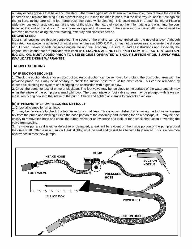
THE FOLLOWING INFORMATION SHOULD ENABLE YOU TO UNDERSTAND THE BASIC THEORY OF OPERATION OF A PORTABLE DREDGE.
For more complete understanding on this subject, we recommend you read any one of a variety of books availablethrough the Keene Library of Books, such as The Gold Miners Handbook, Dredging for Gold or Advanced DredgingTechniques. The vacuum on a portable dredge is created by a "venturi principal". A volume of water is pumped througha tapered orifice (jet), by a special designed water pump. A high velocity jet stream is created within the jet tube produc-ing a powerful vacuum. As indicated in the diagram gravel is dredged into the suction hose and is delivered to the sluicejet flare. As a slurry of water and gravel enters the jet flare and is spread evenly over a classifier screen. The smaller andheavier particles drop below the classifier screen into an area of less velocity, allowing a slower and more selective clas-sification of values. Often values are recovered and easily observed before they even enter the riffle section. The lighternon bearing values and larger aggregate are returned back into the water. The riffles, or gold traps in the sluice box arebest described as "Hungarian Riffles". This type of riffle has proven to be the most efficient gold recovery system. Asmaterial flows over the riffles, a vortex, or eddy current is formed between each riffle opening. This force allows the heav-ier material to settle out of suspension and the lighter, non value bearing material to be washed away. This continuousself cleaning principal allows a dredge to be operated for prolonged periods of time. Normal conditions require a sluicebox to be cleaned only once or twice a day. PRIMING THE PUMPBefore starting the engine, the pump must be fully primed. This means the pump must be full of water and all airremoved. All jetting pumps provided with our dredges have a mechanical water pump seal. Without the presence ofwater in the pump, friction could cause a seal to overheat and require replacement. Priming the pump on some of thesmaller models is accomplished by thrusting the foot valve back and forth under the surface of the water in a reciprocat-ing motion. This will pump water into the foot valve assembly and into the pump. A pump is fully primed when water isobserved flowing out of the discharge end of the pump. It may sometimes become necessary to hold the dischargehose above the level of the pump to complete the priming operation. The larger dredges that have a rigid foot valve, areeasily primed by removing the cap provided on the foot valve and filling, until water overflows. Caution must be exercisedto prevent sand from entering the foot valve or intake portion of the pump. Excess amounts of sand could damage thewater pump seal, or pump impeller. It is recommended that the intake portion of the foot valve be placed in a sand freeenvironment underwater, such as a small bucket or pan. PRIMING THE SUCTION HOSEPriming the suction hose need not be of concern in most dredging operations, but is important to understand the princi-pal. When the tip of the suction hose is taken out of the water during operation air will enter the suction system andcause the suction power to cease temporarily, until submerged again. The suction will commence as soon as the air haspassed through the system. It is important to ensure that no air leaks occur in the suction system. SUCTION SYSTEM OBSTRUCTIONSThe suction system can become jammed while dredging. This can be caused by dredging an excess of sand, causingthe suction hose to load up, or a rock that has become stuck in the suction system. Rock jams generally occur in the jet,or just before entry into the jet. This can easily be cleared by removed by flipping the rubber damper back over the jetflare and thrusting the probe rod down through the jet flare and jet in an effort to strike the obstructed area. It may occa-sionally be necessary to remove the suction hose to remove an obstruction. If this is not successful. it may be necessaryto locate the blockage in the transparent hose and dislodge it by a striking the obstruction, taking care not to damage thehose. SOLID CONTENTCare must be exercised to prevent dredging excess amounts of sand. A solid to water balance must be maintained. Thesolid content being dredged should never exceed 10%. If a suction tip is buried in the sand and not metered properly thesolid content could cause the suction hose to become overloaded with solids and suction will cease, this will also causethe sluice box to become overloaded with solid content, resulting in a loss of values.SLUICE BOX ADJUSTMENTMost models have a slight adjustment to raise or lower the sluice box. The proper sluice box adjustment can effect therecovery of values. If the sluice does not have enough angle, the sluice box will "load up" causing the riffle openings tofill with unwanted excess material. Too much angle will cause the material to flow too fast, resulting in loss of values, evi-denced by the riffles running too clean. The optimum adjustment of a properly working sluice box is evident by only aportion of the riffle is visible while operating. A loss of values can also occur if the solid content of the suction discharge istoo heavy in solid content. Remember, the solid content should not exceed 10 %. A normal sluice box tilt is approximate-ly 3/4” inch to the running foot. Afour foot sluice box should have an approximate tilt of 3" CLEANING THE SLUICE BOXBefore attempting to clean the sluice box, it should be allowed to run with only water for a few minutes in order to wash
out any excess gravels that have accumulated. Either turn engine off, or let run with a slow idle, then remove the classifi-er screen and replace the wing nut to prevent losing it. Unsnap the riffle latches, fold the riffle tray up, and let rest againstthe jet flare, taking care not to let it drop back into place while cleaning. This could result in a potential injury! Place awide tray, bucket or large gold pan at the end of the sluice, then carefully roll up the riffle matting and wash into the con-tainer at the end of the sluice. Rinse any excess gravel that remains in the sluice into container. All material must beremoved before replacing the riffle matting, riffle tray and classifier screen. ENGINE SPEEDMost small engines are throttle controlled. The speed of the engine can be controlled with the use of a lever. Althoughthe rated horsepower is achieved on most small engines at 3600 R.P.M., it may not be necessary to operate the dredgeat full speed. Lower speeds conserve engine life and fuel economy. Be sure to read all instructions and especially theengine instructions that are provided with each unit. ENGINES ARE NOT SHIPPED FROM THE FACTORY CONTAIN-ING OIL. OIL MUST ADDED PRIOR TO USE! ENGINES OPERATED WITHOUT SUFFICIENT OIL S U P P LY W I L LINVALIDATE ENGINE WARRANTEE!
TROUBLE SHOOTING
[A] IF SUCTION DECLINES 1. Check the suction device for an obstruction. An obstruction can be removed by probing the obstructed area with theprovided probe rod. I may be necessary to check the suction hose for a visible obstruction. This can be remedied byeither back flushing the system or dislodging the obstruction with a gentle blow. 2. Check the pump for loss of prime or blockage. The foot valve may be too close to the surface of the water and air mayenter the intake of the pump via a small whirlpool. The pump intake or foot valve screen may be plugged with leaves ormoss, restricting flow into the intake of the pump. Check and tighten all clamps to prevent an air leak.
[B] IF PRIMING THE PUMP BECOMES DIFFICULT1. Check all clamps for an air leak. 2. It may be necessary to check the foot valve for a small leak. This is accomplished by removing the foot valve assem-bly from the pump and blowing air into the hose portion of the assembly and listening for an air escape. It may be nec-essary to remove the hose and check the rubber valve for an evidence of a leak, or for a small obstruction preventing thevalve from sealing. 3. If a water pump seal is either defective or damaged, a leak will be evident on the inside portion of the pump aroundthe drive shaft. Often a new pump will leak slightly, until the seal and gasket has become fully seated. This is a commonoccurrence in most new pumps.
PUMP
SUCTIONNOZZLE
SUCTION HOSE
POWER JET
RIFFLES
SLUICE BOX
FOOT VALVE
INTAKE HOSE
PRESSUREHOSE

INSTALLATION NOTES:The rotation of all is counter-clockwise. Water must be contained within the pump while it is running. Do not run thepump dry, as it will damage the pump seal and may lead to the need to replace the seal. To ensure continuousperformance, it is always a good idea to carry a spare seal, in case you need to replace it. For maximum pumpperformance, use only Keene Engineering foot valves.
INSTALLATION INSTRUCTIONS:1. Before installing the mounting plate (7) to the engine, the spring portion of the water pump seal (5) must be installed.Place this portion of the seal into the center of the mounting plate, with the use of a light hammer and or bluntinstrument and a seal setting tool. Tap the perimeter metal portion of the seal to set the seal into position. Care must betaken to avoid contact with the carbon portion of the seal. A small amount of Silicone Rubber Cement placed in this sectionwill insure a water tight seal. Insert the FOURmounting bolts (6) into the mounting plate (7). Tighten the boltsevenly so as to prevent mis-alignment. 2. Fit "O" Ring gasket (OR1) into "O" slot on the front face of the mounting plate, making sure that it is properly seated.Place the ceramic portion of the water pump seal (4) into the center of the impeller (3) firmly, using the heal of your handto insure a proper fit. The ceramic surface of the seal must be facing outwards. Thread the impeller onto the engine shaftby turning it gently in a clockwise rotation, taking care to avoid damage to the threads on the impeller.3. Attach the outer housing (2) to the mounting plate, using the housing bolts (8) and washers (8A). Tighten the housingbolts evenly to ensure proper tension and alignment. Extreme care must be taken to prevent over tightening of the bolts.Too much torque will damage the threads in the outer housing.
CENTRIFUGAL PUMP ASSEMBLYSTANDARD 5/8" THREADED SHAFT ENGINE
1 2 3 4 6 8 97
1012 THREADED
ENGINESHAFT
5
11
PHP160 & P180 PUMP PARTSPART NO. PART NO.
ITEM DESCRIPTION QUANTITY PHP160 P1801 Hose Adapter 1 HA22 Outer Housing 1 161 1813 Impeller 1 162 1824 Pump Seal (ceramic) 1 WPS (PT#1) WPS (PT#1)5 Pump Seal (Spring & Casing) 1 WPS (PT#2) WPS (PT#2)6 Mounting Plate Bolt 3 MB MB7 Mounting Back Plate 1 105 1058 Housing Bolt 4 HB HB
8A Housing Bolt Washer 4 HW HW9 Shaft Bushing 1 SB SB
9A Compressor Drive 1 P3 P310 O Ring Gasket 1 104 10411 Flusher Adapter Cap 1 FAC FAC12 Flusher Adapter 1 FA FA13 Flusher Adapter Seal (inside Cap) 1 FACS FACS
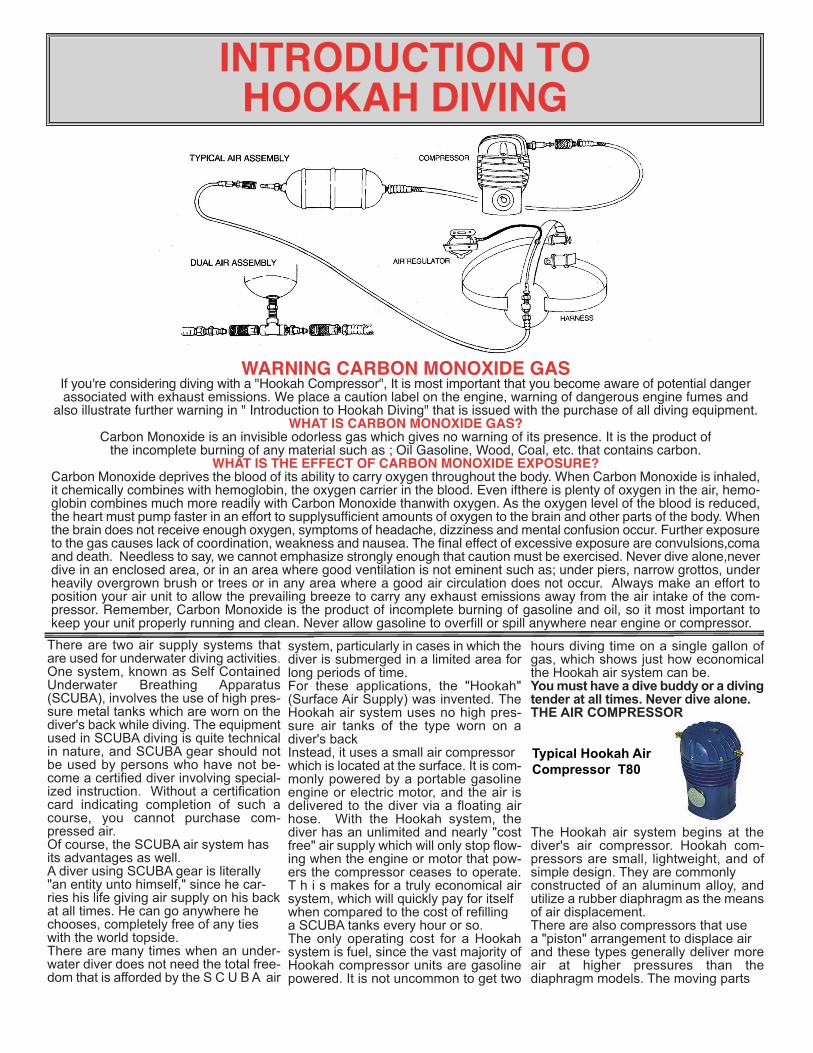
There are two air supply systems thatare used for underwater diving activities.One system, known as Self ContainedUnderwater Breathing Apparatus(SCUBA), involves the use of high pres-sure metal tanks which are worn on thediver's back while diving. The equipmentused in SCUBA diving is quite technicalin nature, and SCUBA gear should notbe used by persons who have not be-come a certified diver involving special-ized instruction. Without a certificationcard indicating completion of such acourse, you cannot purchase com-pressed air.Of course, the SCUBA air system hasits advantages as well.A diver using SCUBA gear is literally"an entity unto himself," since he car-ries his life giving air supply on his backat all times. He can go anywhere hechooses, completely free of any tieswith the world topside.There are many times when an under-water diver does not need the total free-dom that is afforded by the S C U B A air
system, particularly in cases in which thediver is submerged in a limited area forlong periods of time.For these applications, the "Hookah"(Surface Air Supply) was invented. TheHookah air system uses no high pres-sure air tanks of the type worn on adiver's backInstead, it uses a small air compressorwhich is located at the surface. It is com-monly powered by a portable gasolineengine or electric motor, and the air isdelivered to the diver via a floating airhose. With the Hookah system, thediver has an unlimited and nearly "costfree" air supply which will only stop flow-ing when the engine or motor that pow-ers the compressor ceases to operate.T h i s makes for a truly economical airsystem, which will quickly pay for itselfwhen compared to the cost of refillinga SCUBA tanks every hour or so.The only operating cost for a Hookahsystem is fuel, since the vast majority ofHookah compressor units are gasolinepowered. It is not uncommon to get two
hours diving time on a single gallon ofgas, which shows just how economicalthe Hookah air system can be. You must have a dive buddy or a divingtender at all times. Never dive alone. THE AIR COMPRESSOR
The Hookah air system begins at thediver's air compressor. Hookah com-pressors are small, lightweight, and ofsimple design. They are commonlyconstructed of an aluminum alloy, andutilize a rubber diaphragm as the meansof air displacement.There are also compressors that usea "piston" arrangement to displace airand these types generally deliver moreair at higher pressures than thediaphragm models. The moving parts
WARNING CARBON MONOXIDE GASIf you're considering diving with a "Hookah Compressor", It is most important that you become aware of potential dangerassociated with exhaust emissions. We place a caution label on the engine, warning of dangerous engine fumes and
also illustrate further warning in " Introduction to Hookah Diving" that is issued with the purchase of all diving equipment.WHAT IS CARBON MONOXIDE GAS?
Carbon Monoxide is an invisible odorless gas which gives no warning of its presence. It is the product ofthe incomplete burning of any material such as ; Oil Gasoline, Wood, Coal, etc. that contains carbon.
WHAT IS THE EFFECT OF CARBON MONOXIDE EXPOSURE?Carbon Monoxide deprives the blood of its ability to carry oxygen throughout the body. When Carbon Monoxide is inhaled,it chemically combines with hemoglobin, the oxygen carrier in the blood. Even ifthere is plenty of oxygen in the air, hemo-globin combines much more readily with Carbon Monoxide thanwith oxygen. As the oxygen level of the blood is reduced,the heart must pump faster in an effort to supplysufficient amounts of oxygen to the brain and other parts of the body. Whenthe brain does not receive enough oxygen, symptoms of headache, dizziness and mental confusion occur. Further exposureto the gas causes lack of coordination, weakness and nausea. The final effect of excessive exposure are convulsions,comaand death. Needless to say, we cannot emphasize strongly enough that caution must be exercised. Never dive alone,neverdive in an enclosed area, or in an area where good ventilation is not eminent such as; under piers, narrow grottos, underheavily overgrown brush or trees or in any area where a good air circulation does not occur. Always make an effort toposition your air unit to allow the prevailing breeze to carry any exhaust emissions away from the air intake of the com-pressor. Remember, Carbon Monoxide is the product of incomplete burning of gasoline and oil, so it most important tokeep your unit properly running and clean. Never allow gasoline to overfill or spill anywhere near engine or compressor.
INTRODUCTION TO HOOKAH DIVING
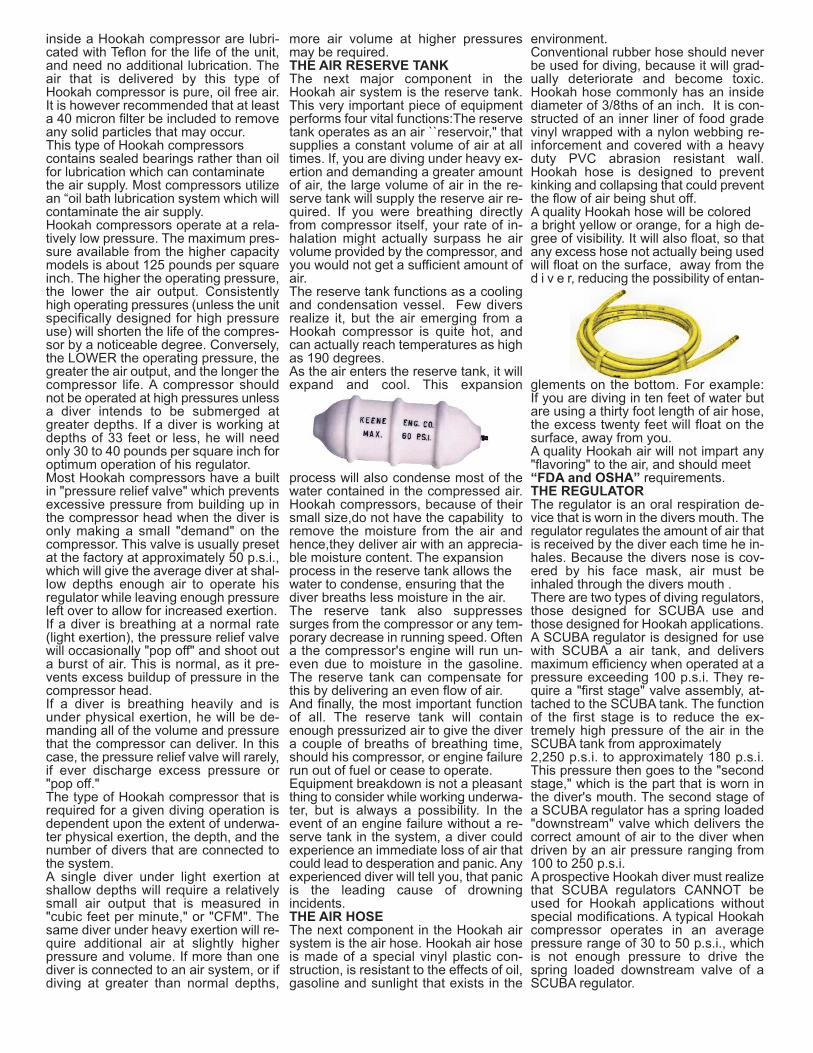
Typical Hookah AirCompressor T80
inside a Hookah compressor are lubri-cated with Teflon for the life of the unit,and need no additional lubrication. Theair that is delivered by this type ofHookah compressor is pure, oil free air.It is however recommended that at leasta 40 micron filter be included to removeany solid particles that may occur.This type of Hookah compressorscontains sealed bearings rather than oilfor lubrication which can contaminatethe air supply. Most compressors utilizean “oil bath lubrication system which willcontaminate the air supply.Hookah compressors operate at a rela-tively low pressure. The maximum pres-sure available from the higher capacitymodels is about 125 pounds per squareinch. The higher the operating pressure,the lower the air output. Consistentlyhigh operating pressures (unless the unitspecifically designed for high pressureuse) will shorten the life of the compres-sor by a noticeable degree. Conversely,the LOWER the operating pressure, thegreater the air output, and the longer thecompressor life. A compressor shouldnot be operated at high pressures unlessa diver intends to be submerged atgreater depths. If a diver is working atdepths of 33 feet or less, he will needonly 30 to 40 pounds per square inch foroptimum operation of his regulator.Most Hookah compressors have a builtin "pressure relief valve" which preventsexcessive pressure from building up inthe compressor head when the diver isonly making a small "demand" on thecompressor. This valve is usually presetat the factory at approximately 50 p.s.i.,which will give the average diver at shal-low depths enough air to operate hisregulator while leaving enough pressureleft over to allow for increased exertion.If a diver is breathing at a normal rate(light exertion), the pressure relief valvewill occasionally "pop off" and shoot outa burst of air. This is normal, as it pre-vents excess buildup of pressure in thecompressor head.If a diver is breathing heavily and isunder physical exertion, he will be de-manding all of the volume and pressurethat the compressor can deliver. In thiscase, the pressure relief valve will rarely,if ever discharge excess pressure or"pop off."The type of Hookah compressor that isrequired for a given diving operation isdependent upon the extent of underwa-ter physical exertion, the depth, and thenumber of divers that are connected tothe system.A single diver under light exertion atshallow depths will require a relativelysmall air output that is measured in"cubic feet per minute," or "CFM". Thesame diver under heavy exertion will re-quire additional air at slightly higherpressure and volume. If more than onediver is connected to an air system, or ifdiving at greater than normal depths,
more air volume at higher pressuresmay be required.THE AIR RESERVE TANKThe next major component in theHookah air system is the reserve tank.This very important piece of equipmentperforms four vital functions:The reservetank operates as an air ``reservoir," thatsupplies a constant volume of air at alltimes. If, you are diving under heavy ex-ertion and demanding a greater amountof air, the large volume of air in the re-serve tank will supply the reserve air re-quired. If you were breathing directlyfrom compressor itself, your rate of in-halation might actually surpass he airvolume provided by the compressor, andyou would not get a sufficient amount ofair.The reserve tank functions as a coolingand condensation vessel. Few diversrealize it, but the air emerging from aHookah compressor is quite hot, andcan actually reach temperatures as highas 190 degrees.As the air enters the reserve tank, it willexpand and cool. This expansion
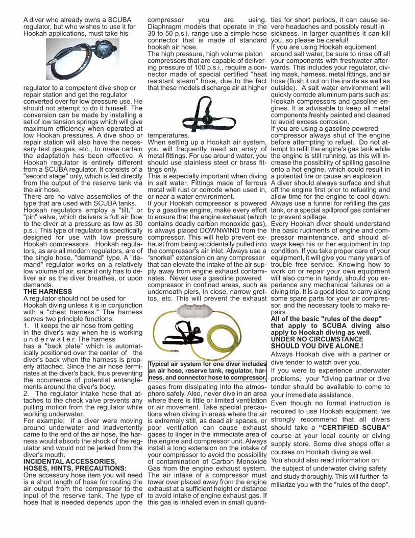
process will also condense most of thewater contained in the compressed air.Hookah compressors, because of theirsmall size,do not have the capability toremove the moisture from the air andhence,they deliver air with an apprecia-ble moisture content. The expansionprocess in the reserve tank allows thewater to condense, ensuring that thediver breaths less moisture in the air.The reserve tank also suppressessurges from the compressor or any tem-porary decrease in running speed. Oftena the compressor's engine will run un-even due to moisture in the gasoline.The reserve tank can compensate forthis by delivering an even flow of air.And finally, the most important functionof all. The reserve tank will containenough pressurized air to give the divera couple of breaths of breathing time,should his compressor, or engine failurerun out of fuel or cease to operate.Equipment breakdown is not a pleasantthing to consider while working underwa-ter, but is always a possibility. In theevent of an engine failure without a re-serve tank in the system, a diver couldexperience an immediate loss of air thatcould lead to desperation and panic. Anyexperienced diver will tell you, that panicis the leading cause of drowningincidents.THE AIR HOSEThe next component in the Hookah airsystem is the air hose. Hookah air hoseis made of a special vinyl plastic con-struction, is resistant to the effects of oil,gasoline and sunlight that exists in the
environment.Conventional rubber hose should neverbe used for diving, because it will grad-ually deteriorate and become toxic.Hookah hose commonly has an insidediameter of 3/8ths of an inch. It is con-structed of an inner liner of food gradevinyl wrapped with a nylon webbing re-inforcement and covered with a heavyduty PVC abrasion resistant wall.Hookah hose is designed to preventkinking and collapsing that could preventthe flow of air being shut off.A quality Hookah hose will be coloreda bright yellow or orange, for a high de-gree of visibility. It will also float, so thatany excess hose not actually being usedwill float on the surface, away from thed i v e r, reducing the possibility of entan-
glements on the bottom. For example:If you are diving in ten feet of water butare using a thirty foot length of air hose,the excess twenty feet will float on thesurface, away from you.A quality Hookah air will not impart any"flavoring" to the air, and should meet“FDA and OSHA” requirements.THE REGULATORThe regulator is an oral respiration de-vice that is worn in the divers mouth. Theregulator regulates the amount of air thatis received by the diver each time he in-hales. Because the divers nose is cov-ered by his face mask, air must beinhaled through the divers mouth .There are two types of diving regulators,those designed for SCUBA use andthose designed for Hookah applications.A SCUBA regulator is designed for usewith SCUBA a air tank, and deliversmaximum efficiency when operated at apressure exceeding 100 p.s.i. They re-quire a "first stage" valve assembly, at-tached to the SCUBA tank. The functionof the first stage is to reduce the ex-tremely high pressure of the air in theSCUBA tank from approximately2,250 p.s.i. to approximately 180 p.s.i.This pressure then goes to the "secondstage," which is the part that is worn inthe diver's mouth. The second stage ofa SCUBA regulator has a spring loaded"downstream" valve which delivers thecorrect amount of air to the diver whendriven by an air pressure ranging from100 to 250 p.s.i.A prospective Hookah diver must realizethat SCUBA regulators CANNOT beused for Hookah applications withoutspecial modifications. A typical Hookahcompressor operates in an averagepressure range of 30 to 50 p.s.i., whichis not enough pressure to drive thespring loaded downstream valve of aSCUBA regulator.
A diver who already owns a SCUBAregulator, but who wishes to use it forHookah applications, must take his
regulator to a competent dive shop orrepair station and get the regulatorconverted over for low pressure use. Heshould not attempt to do it himself. Theconversion can be made by installing aset of low tension springs which will givemaximum efficiency when operated atlow Hookah pressures. A dive shop orrepair station will also have the neces-sary test gauges, etc., to make certainthe adaptation has been effective. AHookah regulator is entirely differentfrom a SCUBA regulator. It consists of a"second stage" only, which is fed directlyfrom the output of the reserve tank viathe air hose.There are no valve assemblies of thetype that are used with SCUBA tanks.Hookah regulators employ a "tilt," or"pin" valve, which delivers a full air flowto the diver at a pressure as low as 30p.s.i. This type of regulator is specificallydesigned for use with low pressureHookah compressors. Hookah regula-tors, as are all modern regulators, are ofthe single hose, "demand" type. A "de-mand" regulator works on a relativelylow volume of air, since it only has to de-liver air as the diver breathes, or upondemands.THE HARNESSA regulator should not be used forHookah diving unless it is in conjunctionwith a "chest harness." The harnessserves two principle functions:1. It keeps the air hose from gettingin the diver's way when he is workingu n d e r w a t e r. The harness has a "back plate" which is automat-ically positioned over the center of thediver's back when the harness is prop-erly attached. Since the air hose termi-nates at the diver's back, thus preventingthe occurrence of potential entangle-ments around the diver's body.2. The regulator intake hose that at-taches to the check valve prevents anypulling motion from the regulator whileworking underwater. For example; if a diver were movingaround underwater and inadvertentlycame to the end of the air hose, the har-ness would absorb the shock of the reg-ulator and would not be jerked from thediver's mouth.INCIDENTAL ACCESSORIES,HOSES, HINTS, PRECAUTIONS:One accessory hose item you will needis a short length of hose for routing theair output from the compressor to theinput of the reserve tank. The type ofhose that is needed depends upon the
compressor you are using.Diaphragm models that operate in the30 to 50 p.s.i. range use a simple hoseconnector that is made of standardhookah air hose.The high pressure, high volume pistoncompressors that are capable of deliver-ing pressure of 100 p.s.i., require a con-nector made of special certified "heatresistant steam" hose, due to the factthat these models discharge air at higher
temperatures.When setting up a Hookah air system,you will frequently need an array ofmetal fittings. For use around water, youshould use stainless steel or brass fit-tings only. This is especially important when divingin salt water. Fittings made of ferrousmetal will rust or corrode when used in,or near a water environment.If your Hookah compressor is poweredby a gasoline engine, make every effortto ensure that the engine exhaust (whichcontains deadly carbon monoxide gas),is always placed DOWNWIND from thecompressor. This will help prevent ex-haust from being accidentally pulled intothe compressor's air inlet. Always use a“snorkel” extension on any compressorthat can elevate the intake of the air sup-ply away from engine exhaust contami-nates. Never use a gasoline poweredcompressor in confined areas, such asunderneath piers, in close, narrow grot-tos, etc. This will prevent the exhaust
gases from dissipating into the atmos-phere safely. Also, never dive in an areawhere there is little or limited ventilationor air movement. Take special precau-tions when diving in areas where the airis extremely still, as dead air spaces, orpoor ventilation can cause exhaustgases to linger in the immediate area ofthe,engine and compressor unit. Alwaysinstall a long extension on the intake ofyour compressor to avoid the possibilityof contamination of Carbon MonoxideGas from the engine exhaust system.The air intake of a compressor musttower over placed away from the engineexhaust at a sufficient height or distanceto avoid intake of engine exhaust gas. Ifthis gas is inhaled even in small quanti-
ties for short periods, it can cause se-vere headaches and possibly result insickness. In larger quantities it can killyou, so please be careful!If you are using Hookah equipmentaround salt water, be sure to rinse off allyour components with freshwater after-wards. This includes your regulator, div-ing mask, harness, metal fittings, and airhose (flush it out on the inside as well asoutside). A salt water environment willquickly corrode aluminum parts such as:Hookah compressors and gasoline en-gines. It is advisable to keep all metalcomponents freshly painted and cleanedto avoid excess corrosion.If you are using a gasoline poweredcompressor always shut of the enginebefore attempting to refuel. Do not at-tempt to refill the engine's gas tank whilethe engine is still running, as this will in-crease the possibility of spilling gasolineonto a hot engine, which could result ina potential fire or cause an explosion.A diver should always surface and shutoff the engine first prior to refueling andallow time for the engine to cool down.Always use a funnel for refilling the gastank, or a special spillproof gas containerto prevent spillage.Every Hookah diver should understandthe basic rudiments of engine and com-pressor maintenance, and should al-ways keep his or her equipment in topcondition. If you take proper care of yourequipment, it will give you many years oftrouble free service. Knowing how towork on or repair your own equipmentwill also come in handy, should you ex-perience any mechanical failures on adiving trip. It is a good idea to carry alongsome spare parts for your air compres-sor, and the necessary tools to make re-pairs.All of the basic "rules of the deep"that apply to SCUBA diving alsoapply to Hookah diving as well.UNDER NO CIRCUMSTANCESHOULD YOU DIVE ALONE.!Always Hookah dive with a partner ordive tender to watch over you. If you were to experience underwaterproblems, your "diving partner or divetender should be available to come toyour immediate assistance.Even though no formal instruction isrequired to use Hookah equipment, westrongly recommend that all diversshould take a “CERTIFIED SCUBA”course at your local county or divingsupply store. Some dive shops offer acourses on Hookah diving as well. You should also read information onthe subject of underwater diving safetyand study thoroughly. This will further fa-miliarize you with the "rules of the deep".
Typical air system for one diver includesan air hose, reserve tank, regulator, har-ness, and connector hose to compressor.
6
WARNING CARBON MONOXIDE GASIf you're considering diving with a "Hookah Compressor" , It is most important that you become aware ofPotential Danger associated with exhaust emissions. We place a caution label on the engine, warning of dan-gerous engine fumes and also illustrate further warning in " Introduction to Hookah Diving" and Safety inGold Dredging that is issued with the purchase of all diving equipment.
WHAT IS CARBON MONOXIDE GAS?Carbon Monoxide is an invisible odorless gas which gives no warning of its presence. It is the product ofthe incomplete burning of any material such as ; Oil Gasoline, Wood, Coal, etc. that contains carbon.
WHAT IS THE EFFECT OF CARBON MONOXIDE EXPOSURE?Carbon Monoxide deprives the blood of its ability to carry oxygen throughout the body. When CarbonMonoxide is inhaled , it chemically combines with hemoglobin, the oxygen carrier in the blood. Even ifthere is plenty of oxygen in the air, hemoglobin combines much more readily with Carbon Monoxide thanwith oxygen. As the oxygen level of the blood is reduced, the heart must pump faster in an effort to sup-ply sufficient amounts of oxygen to the brain and other parts of the body. When the brain does not receiveenough oxygen, symptoms of headache, dizziness and mental confusion occur. Further exposure to the gascauses lack of coordination, weakness and nausea. The final effect of excessive exposure are convulsions,coma and death.
Needless to say, we cannot emphasize strongly enough that caution must be exercised. Never dive alone,never dive in an enclosed area, or in an area where good ventilation is not eminent such as; under piers, nar-row grottos, under heavily overgrown brush or trees or in any area where a good breeze does not occur.Always make an effort to position your air unit to allow the prevailing breeze to carry any exhaust emissionsaway from the air intake of the compressor.
Remember, Carbon Monoxide is the product of incomplete burning of gasoline and oil, so it most importantto keep your unit properly running and clean. Never allow gasoline to overfill or spill anywhere near engineand compressor.
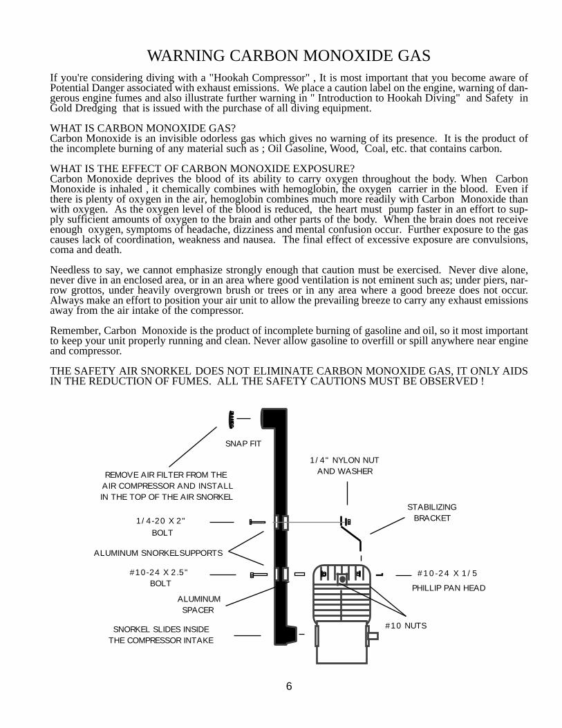
THE SAFETY AIR SNORKEL DOES NOT ELIMINATE CARBON MONOXIDE GAS, IT ONLY AIDSIN THE REDUCTION OF FUMES. ALL THE SAFETY CAUTIONS MUST BE OBSERVED !
REMOVE AIR FILTER FROM THEAIR COMPRESSOR AND INSTALLIN THE TOP OF THE AIR SNORKEL
SNAP FIT
SNORKEL SLIDES INSIDE THE COMPRESSOR INTAKE
1/4-20 X 2"
#10-24 X 2.5"
SPACER
BOLT
BOLT
STABILIZING BRACKET
1/4" NYLON NUTAND WASHER
#10-24 X 1/5
PHILLIP PAN HEAD
#10 NUTS
ALUMINUM
ALUMINUM SNORKELSUPPORTS