product profile 2011 power factor correction - informatio capacitor... · product profile 2011...
TRANSCRIPT
www.epcos.com
Product Profile 2011
Power Factor CorrectionPower Quality Solutions
2 © EPCOS AG 2011
EPCOS is a leading manufacturer of electronic components, modules and systems.
Our broad portfolio includes capacitors, inductors and ferrites, EMC filters, sensors
and sensor systems, nonlinear resistors, and arresters, as well as SAW and BAW
components and RF modules. As an innovative technology-driven company, EPCOS
focuses technologically demanding growth markets in the areas of information and
communications technology, automotive, industrial, and consumer electronics. We
offer our customers both standard components as well as application-specific
solutions.
EPCOS has design, manufacturing and marketing facilities in Europe, Asia
and the Americas. We are continuously strengthening our global research and
development network by expanding R&D activities at our production locations,
primarily in Eastern Europe, China and India. With our global presence we are able
to provide our customers with local development and manufacturing know-how
and support in the early phases of their projects.
EPCOS is continually improving its processes and thus the quality of its products
and services. The Group is ISO/TS 16949 certified and remains committed to
constantly reviewing and systematically improving its quality management system.
Welcome to the World of Electronic Components and Modules
© EPCOS AG 2011 3
Power Quality Solutions
ContentsPreview 4PFC capacitor series overview 8PQS key components overview 10Important notes 12PFC capacitors� PhaseCap Premium (230 … 800 V, 5.0 … 33 kvar) 13� PhaseCap Compact (230 … 1000 V, 5.0 … 33 kvar) 20� PhaseCap HD (400 … 525 V, 40 … 60 kvar) 26� PhiCap (230 … 525 V, 0.5 … 30 kvar) 29� MKV capacitors (400 … 800 V, 4.2 … 30 kvar) 36PF controllers and measuring devices� BR604, BR6000, BR7000 series and BR7000-SOFT 40� Multi Measuring Interfaces 50� Grid analysis tool MC7000-3 52Switching devices� Capacitor contactors 54� Thryristor modules for dynamic PFC (TSM-series) 57Reactors� Reactors – Antiresonance harmonic filter 61� Discharge reactor 64Fundamentals of Power Factor Correction 65� Components for Power Factor Correction 66� Standard values: Selection tables for cables, cable cross sections and fuses 69� Calculation table for reactive power demand (Qc) 71� Individual PFC for motors 72� Individual PFC for transformers 73� Detuned PFC in general 74� Detuned PFC: Important facts and instructions 75� Component selection tables for detuned PFC 76� Dynamic PFC: Important facts and instructions 80� Component selection tables for dynamic PFC 81� PFC basic formulas 84Cautions 87Addresses 92
4 © EPCOS AG 2011
Preview
General
The increasing demand of electricalpower and the awareness of the necessity of energy saving is very upto date these days. Also the aware-ness of power quality is increasing,and power factor correction (PFC) andharmonic filtering will be implementedon a growing scale. Enhancing powerquality – improvement of power factor– saves costs and ensures a fast return on investment. In power distrib-ution, in low- and medium-voltagenetworks, PFC focuses on the powerflow (cos ϕ) and the optimization ofvoltage stability by generating reactivepower – to im prove voltage quality andreliability at distribution level.
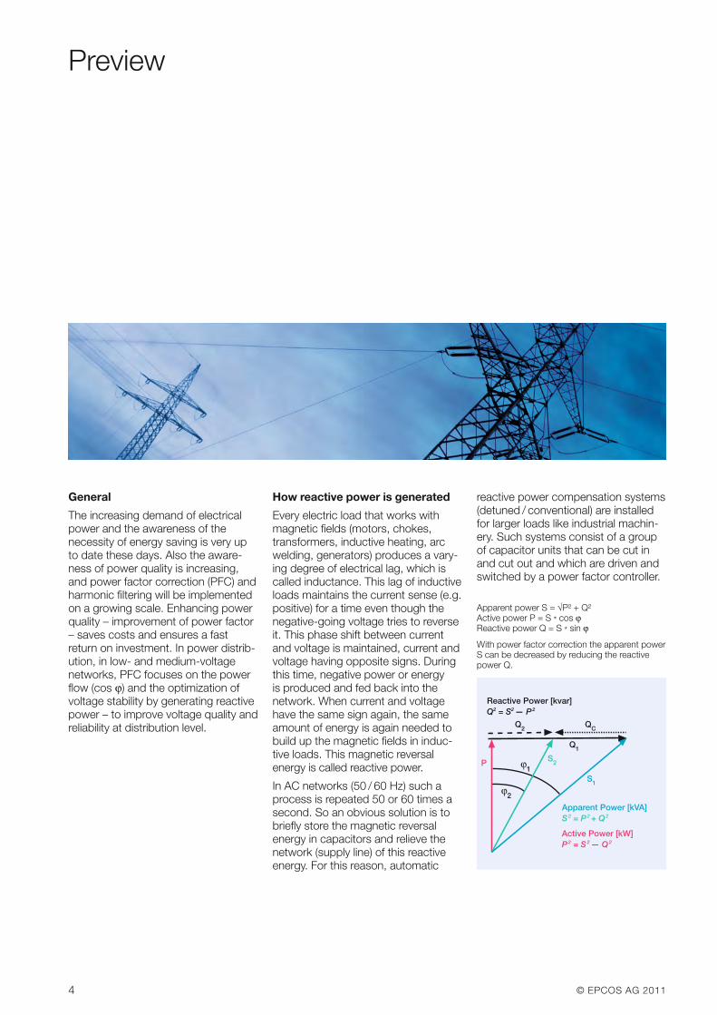
How reactive power is generated
Every electric load that works withmagnetic fields (motors, chokes,transformers, inductive heating, arcwelding, generators) produces a vary-ing degree of electrical lag, which iscalled inductance. This lag of inductiveloads maintains the current sense (e.g.positive) for a time even though thenegative-going voltage tries to reverseit. This phase shift between currentand voltage is maintained, current andvoltage having opposite signs. Duringthis time, negative power or energy is produced and fed back into the network. When current and voltagehave the same sign again, the sameamount of energy is again needed tobuild up the magnetic fields in induc-tive loads. This magnetic reversal energy is called reactive power.
In AC networks (50 / 60 Hz) such aprocess is repeated 50 or 60 times asecond. So an obvious solution is tobriefly store the magnetic reversal energy in capacitors and relieve thenetwork (supply line) of this reactiveenergy. For this reason, automatic
reactive power compensation systems(detuned / conventional) are installedfor larger loads like industrial machin-ery. Such systems consist of a groupof capacitor units that can be cut inand cut out and which are driven andswitched by a power factor controller.
Reactive Power [kvar]Q2 = S2 — P2
Q2 QC
Q1
S2
S1
ϕ1P
ϕ2
Apparent Power [kVA]S2 = P2 + Q2
Active Power [kW]P2 = S2 — Q2
Apparent power S = √P² + Q²Active power P = S * cos ϕReactive power Q = S * sin ϕ
With power factor correction the apparent powerS can be decreased by reducing the reactivepower Q.
© EPCOS AG 2011 5
Preview
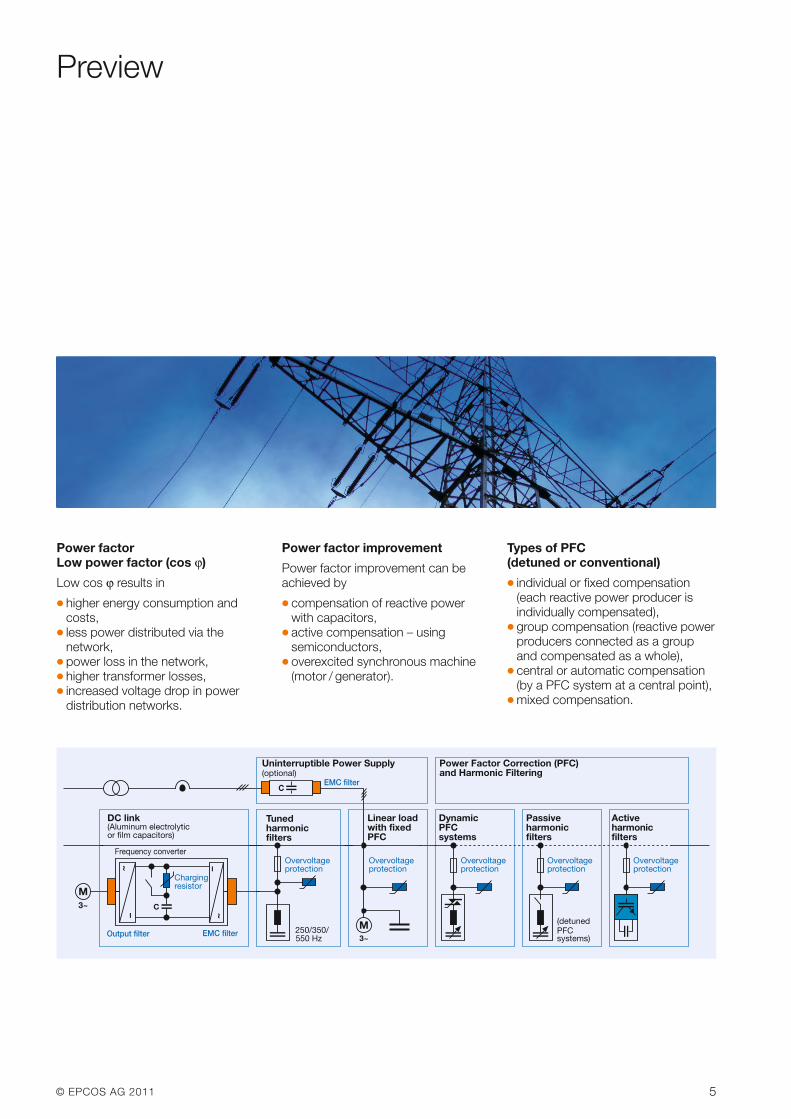
Power factorLow power factor (cos ϕ)
Low cos ϕ results in
� higher energy consumption andcosts,
� less power distributed via the network,
� power loss in the network,� higher transformer losses,� increased voltage drop in power
distribution networks.
Power factor improvement
Power factor improvement can beachieved by
� compensation of reactive power with capacitors,
� active compensation – using semiconductors,
� overexcited synchronous machine(motor / generator).
Types of PFC (detuned or conventional)
� individual or fixed compensation(each reactive power producer isindividually compensated),
� group compensation (reactive powerproducers connected as a groupand compensated as a whole),
� central or automatic compen sation(by a PFC system at a central point),
� mixed compensation.
M3~
Uninterruptible Power Supply(optional)
EMC filterC
250/350/ 550 Hz
Overvoltageprotection
Tunedharmonicfilters
Linear loadwith fixedPFC
M3~
Overvoltageprotection
DynamicPFCsystems
Overvoltageprotection
Passiveharmonicfilters
(detuned PFCsystems)
Overvoltageprotection
Overvoltageprotection
Activeharmonicfilters
Power Factor Correction (PFC)and Harmonic Filtering
DC link(Aluminum electrolyticor film capacitors)
EMC filter
Frequency converter
C
Chargingresistor
Output filter
6 © EPCOS AG 2011
Preview
PQS strategy
Along with the emerging demand forpower quality and a growing aware-ness of the need for environmentalprotection, the complexity in the ener-gy market is increasing: users and decision-makers are consequentlyfinding it increasingly difficult to locate
the best product on the market and tomake objective decisions. It is in mostcases not fruitful to compare catalogsand data sheets, as many of their parameters are identical in line withthe relevant standards. Thus operatingtimes are specified on the basis of
tests under laboratory conditions thatmay differ significantly from the realityin the field. In addition, load structureshave changed from being mainly linearin the past to non-linear today. All thisproduces a clear trend: the market is calling increasingly for customized
© EPCOS AG 2011 7
Preview
solutions rather than off-the-shelfproducts. This is where Power QualitySolutions come into the picture. It of-fers all key components for an effec-tive PFC system from a single source,together with:
� Application know-how� Technical skills� Extensive experience in the field of
power quality improvement� A worldwide network of partners� Continuous development� Sharing of information
These are the cornerstones on whichPower Quality Solutions are built. Onthe basis of this strategy, EPCOS isnot only the leading manufacturer ofpower capacitors for PFC applicationsbut also a PQS supplier with a centuryof field experience, reputation and reliability.
U
I U
I
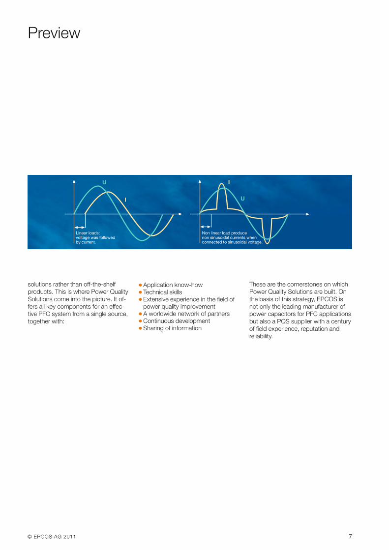
Linear loads:voltage was followed by current.
Non linear load produce non sinusoidal currents when connected to sinusoidal voltage.
8 © EPCOS AG 2011Please read Important notes on page 12 and Cautions on page 87-91.
PFC Capacitor Series Overview
PFC capacitor series for power factor correction and detuned filter
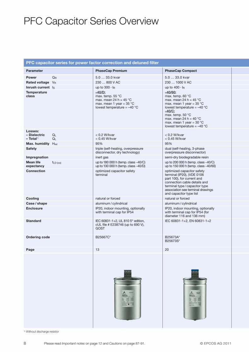
Parameter PhaseCap Premium PhaseCap Compact
Power QR 5.0 … 33.0 kvar 5.0 … 33.0 kvar
Rated voltage VR 230 … 800 V AC 230 … 1000 V AC
Inrush current IS up to 300 · IR up to 400 · IRTemperature –40/D: –40/60:class max. temp. 55 °C max. temp. 60 °C
max. mean 24 h = 45 °C max. mean 24 h = 45 °C max. mean 1 year = 35 °C max. mean 1 year = 35 °C lowest temperature = –40 °C lowest temperature = –40 °C
–40/C:max. temp. 50 °Cmax. mean 24 h = 40 °C max. mean 1 year = 30 °Clowest temperature = –40 °C
Losses:– Dielectric QL < 0.2 W/kvar < 0.2 W/kvar– Total1) QL < 0.45 W/kvar < 0.45 W/kvar
Max. humidity Hrel 95% 95%
Safety triple (self-healing, overpressure dual (self-healing, 3-phase disconnector, dry technology) overpressure disconnector)
Impregnation inert gas semi-dry biodegradable resin
Mean life tLD (co) up to 180 000 h (temp. class –40/C) up to 200 000 h (temp. class –40/C)expectancy up to 130 000 h (temp. class –40/D) up to 150 000 h (temp. class –40/60)
Connection optimized capacitor safety optimized capacitor safetyterminal terminal (IP20), (VDE 0106
part 100), for current and connection cable details and terminal type / capacitor type association see terminal drawingsand capacitor type list
Cooling natural or forced natural or forced
Case / shape aluminum / cylindrical aluminum / cylindrical
Enclosure IP20, indoor mounting, optionally IP20, indoor mounting, optionally with terminal cap for IP54 with terminal cap for IP54 (for
diameter 116 and 136 mm)
Standard IEC 60831-1+2, UL 810 5th edition, IEC 60831-1+2, EN 60831-1+2cUL file # E238746 (up to 690 V),GOST
Ordering code B25667C* B25673A*B25673S*
Page 13 20
1) Without discharge resistor
© EPCOS AG 2011 9Please read Important notes on page 12 and Cautions on page 87-91.
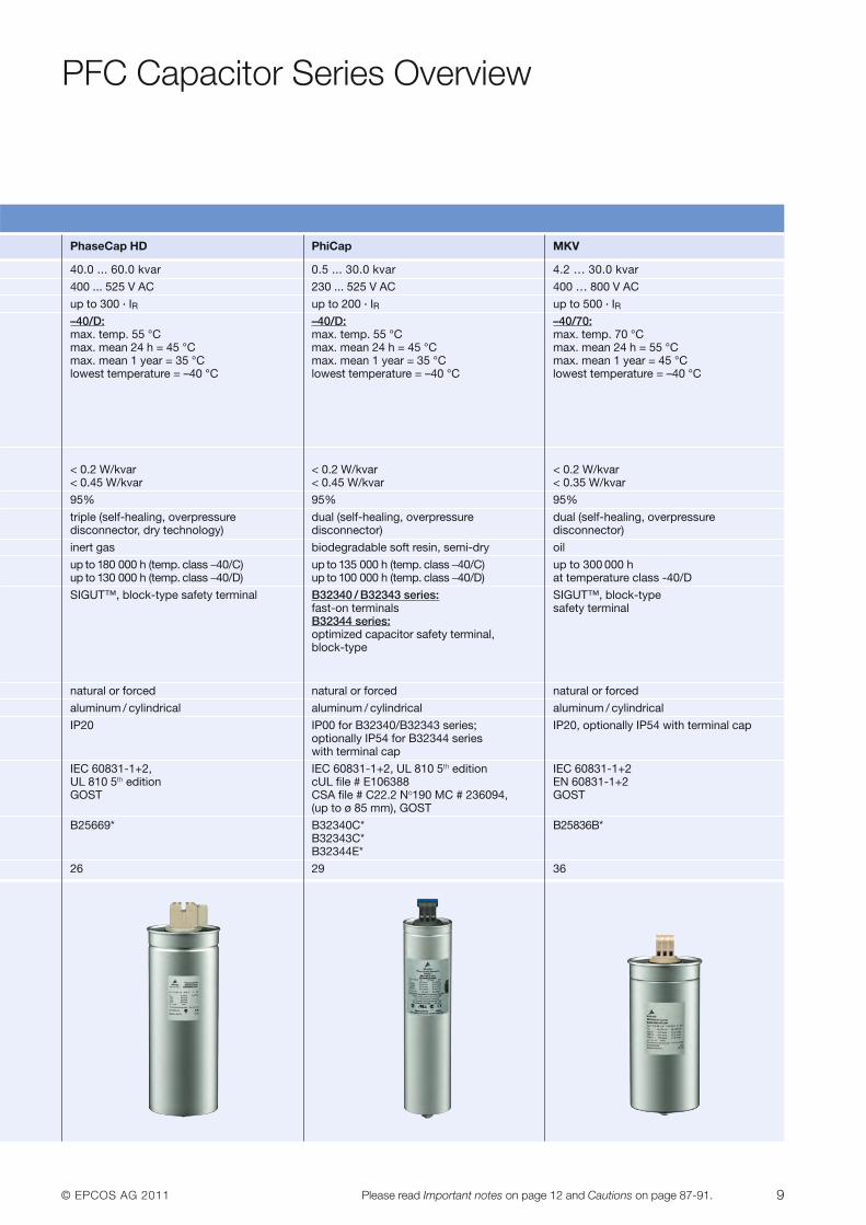
PFC Capacitor Series Overview
PhaseCap HD PhiCap MKV
40.0 ... 60.0 kvar 0.5 ... 30.0 kvar 4.2 … 30.0 kvar
400 ... 525 V AC 230 ... 525 V AC 400 … 800 V AC
up to 300 · IR up to 200 · IR up to 500 · IR–40/D: –40/D: –40/70:max. temp. 55 °C max. temp. 55 °C max. temp. 70 °Cmax. mean 24 h = 45 °C max. mean 24 h = 45 °C max. mean 24 h = 55 °C max. mean 1 year = 35 °C max. mean 1 year = 35 °C max. mean 1 year = 45 °Clowest temperature = –40 °C lowest temperature = –40 °C lowest temperature = –40 °C
< 0.2 W/kvar < 0.2 W/kvar < 0.2 W/kvar< 0.45 W/kvar < 0.45 W/kvar < 0.35 W/kvar
95% 95% 95%
triple (self-healing, overpressure dual (self-healing, overpressure dual (self-healing, overpressuredisconnector, dry technology) disconnector) disconnector)
inert gas biodegradable soft resin, semi-dry oil
up to 180 000 h (temp. class –40/C) up to 135 000 h (temp. class –40/C) up to 300 000 h up to 130 000 h (temp. class –40/D) up to 100 000 h (temp. class –40/D) at temperature class -40/D
SIGUT™, block-type safety terminal B32340 / B32343 series: SIGUT™, block-typefast-on terminals safety terminalB32344 series:optimized capacitor safety terminal,block-type
natural or forced natural or forced natural or forced
aluminum / cylindrical aluminum / cylindrical aluminum / cylindrical
IP20 IP00 for B32340/B32343 series; IP20, optionally IP54 with terminal capoptionally IP54 for B32344 serieswith terminal cap
IEC 60831-1+2, IEC 60831-1+2, UL 810 5th edition IEC 60831-1+2UL 810 5th edition cUL file # E106388 EN 60831-1+2GOST CSA file # C22.2 No190 MC # 236094, GOST
(up to ø 85 mm), GOST
B25669* B32340C* B25836B*B32343C*B32344E*
26 29 36
10 © EPCOS AG 2011Please read Important notes on page 12 and Cautions on page 87-91.
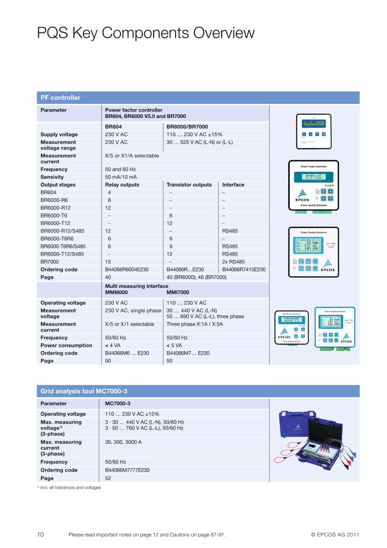
PF controller
Parameter Power factor controller BR604, BR6000 V5.0 and BR7000
BR604 BR6000/BR7000Supply voltage 230 V AC 110 … 230 V AC ±15%
Measurement 230 V AC 30 … 525 V AC (L-N) or (L-L)voltage rangeMeasurement X/5 or X1/A selectablecurrentFrequency 50 and 60 Hz
Sensivity 50 mA/10 mA
Output stages Relay outputs Transistor outputs InterfaceBR604 4 – –
BR6000-R6 6 – –
BR6000-R12 12 – –
BR6000-T6 – 6 –
BR6000-T12 – 12 –
BR6000-R12/S485 12 – RS485
BR6000-T6R6 6 6 –
BR6000-T6R6/S485 6 6 RS485
BR6000-T12/S485 – 12 RS485
BR7000 15 – 2x RS485
Ordering code B44066R6004E230 B44066R…E230 B44066R7415E230
Page 40 40 (BR6000); 46 (BR7000)
Multi measuring interfaceMMI6000 MMI7000
Operating voltage 230 V AC 110 … 230 V AC
Measurement 230 V AC, single phase 30 … 440 V AC (L-N)voltage 50 … 690 V AC (L-L), three phase
Measurement X/5 or X/1 selectable Three phase X:1A / X:5AcurrentFrequency 50/60 Hz 50/60 Hz
Power consumption < 4 VA < 5 VA
Ordering code B44066M6 … E230 B44066M7… E230
Page 50 50
Grid analysis tool MC7000-3
Parameter MC7000-3
Operating voltage 110 … 230 V AC ±15%
Max. measuring 3 · 30 … 440 V AC (L-N), 50/60 Hzvoltage1) 3 · 50 … 760 V AC (L-L), 50/60 Hz(3-phase)
Max. measuring 30, 300, 3000 Acurrent(3-phase)
Frequency 50/60 Hz
Ordering code B44066M7777E230
Page 52
PQS Key Components Overview
1) incl. all tolerances and voltages
© EPCOS AG 2011 11Please read Important notes on page 12 and Cautions on page 87-91.
PQS Key Components Overview
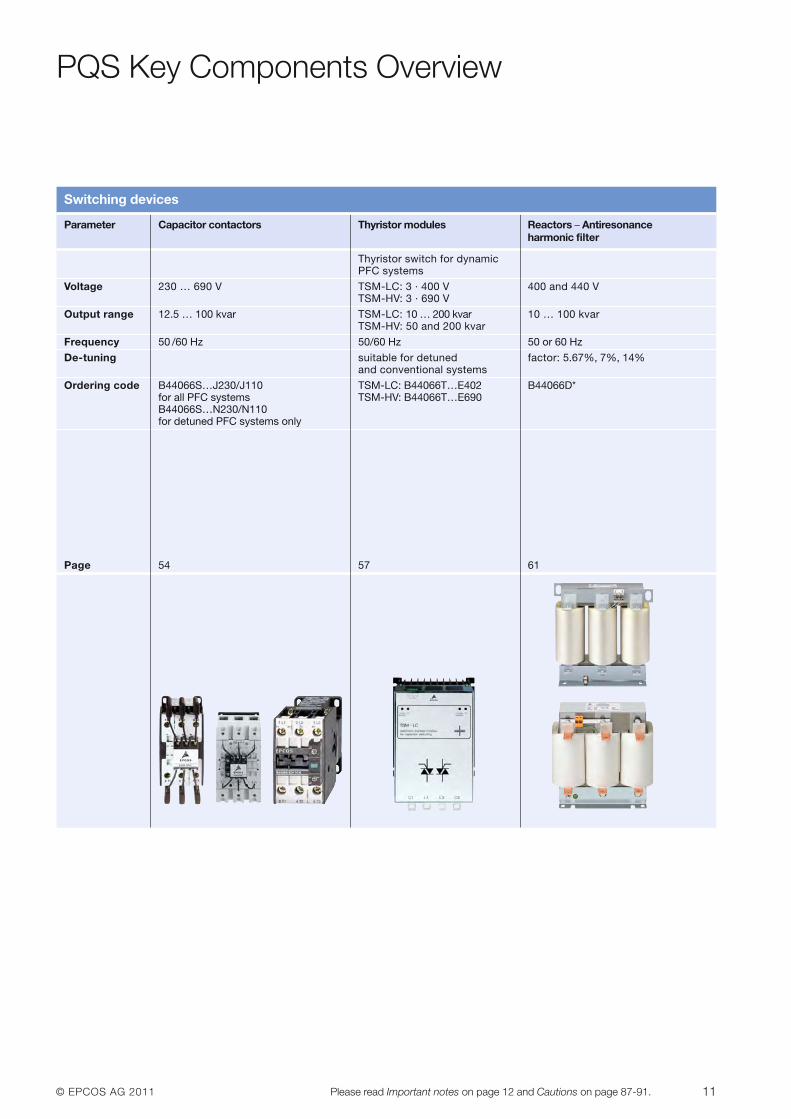
Switching devices
Parameter Capacitor contactors Thyristor modules Reactors – Antiresonance harmonic filter
Thyristor switch for dynamic PFC systems
Voltage 230 … 690 V TSM-LC: 3 · 400 V 400 and 440 VTSM-HV: 3 · 690 V
Output range 12.5 … 100 kvar TSM-LC: 10 … 200 kvar 10 … 100 kvarTSM-HV: 50 and 200 kvar
Frequency 50 /60 Hz 50/60 Hz 50 or 60 Hz
De-tuning suitable for detuned factor: 5.67%, 7%, 14%and conventional systems
Ordering code B44066S…J230/J110 TSM-LC: B44066T…E402 B44066D*for all PFC systems TSM-HV: B44066T…E690B44066S…N230/N110for detuned PFC systems only
Page 54 57 61
12 © EPCOS AG 2011Please read Important notes on page 12 and Cautions on page 87-91.
Important Notes
The following applies to all products named in this publication:
1. Some parts of this publication contain statements aboutthe suitability of our products for certain areas of ap-plication. These statements are based on our knowledgeof typical requirements that are often placed on our prod-ucts in the areas of application concerned. We neverthe-less expressly point out that such statements cannot beregarded as binding statements about the suitabilityof our products for a particular customer application.As a rule, EPCOS is either unfamiliar with individual cus-tomer applications or less familiar with them than the customers themselves. For these reasons, it is always ul-timately incumbent on the customer to check and decidewhether an EPCOS product with the properties describedin the product specification is suitable for use in a partic-ular customer application.
2. We also point out that in individual cases, a malfunc-tion of electronic components or failure before theend of their usual service life cannot be completelyruled out in the current state of the art, even if they areoperated as speci fied. In customer applications requir-ing a very high level of operational safety and especially in customer applications in which the malfunction or failureof an electronic component could endanger human life orhealth (e.g. in accident prevention or life-saving systems),it must therefore be ensured by means of suitable designof the customer application or other action taken by the customer (e.g. installation of protective circuitry or redundancy) that no injury or damage is sustained by thirdparties in the event of malfunction or failure of an electron-ic component.
3. The warnings, cautions and product-specific notesmust be observed.
4. In order to satisfy certain technical requirements, some ofthe products described in this publica tion may containsubstances subject to restrictions in cer tain jurisdic-tions (e.g. because they are classed as hazardous).Useful information on this will be found in our MaterialData Sheets on the Internet (www.epcos.com/material).
Should you have any more detailed questions, please con-tact our sales offices.
5. We constantly strive to improve our products. Conse -quently, the products described in this publicationmay change from time to time. The same is true of thecorresponding product specifications. Please checktherefore to what extent product descriptions and speci-fications contained in this publication are still applicablebefore or when you place an order.
We also reserve the right to discontinue productionand delivery of products. Consequently, we cannotguarantee that all products named in this publication willalways be available.
The aforementioned does not apply in the case of individual agreements deviating from the foregoing forcustomer-specific products.
6. Unless otherwise agreed in individual contracts, all orders are subject to the current version of the “Gen-eral Terms of Delivery for Products and Services in the Electrical Industry” published by the GermanElectrical and Electronics Industry Association (ZVEI).
7. The trade names EPCOS, BAOKE, Alu-X, CeraDiode,CSMP, CSSP, CTVS, DeltaCap, DigiSiMic, DSSP, FormFit, MiniBlue, MiniCell, MKD, MKK, MLSC, MotorCap, PCC, PhaseCap, PhaseCube, PhaseMod, PhiCap, SIFERRIT, SIFI, SIKOREL, SilverCap, SIMDAD,SiMic, SIMID, SineFormer, SIOV, SIP5D, SIP5K, ThermoFuse, WindCap are trademarks regis tered or pending in Europe and in other countries. Further information will be found on the Internet at www.epcos.com/trademarks.
© EPCOS AG 2011 13Please read Important notes on page 12 and Cautions on page 87-91.
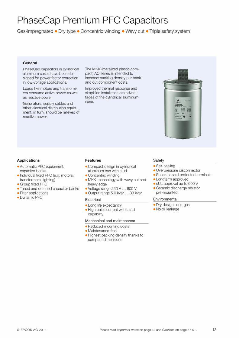
PhaseCap Premium PFC CapacitorsGas-impregnated � Dry type � Concentric winding � Wavy cut � Triple safety system
Applications
� Automatic PFC equipment, capacitor banks
� Individual fixed PFC (e.g. motors,transformers, lighting)
� Group fixed PFC� Tuned and detuned capacitor banks� Filter applications� Dynamic PFC
Features
� Compact design in cylindrical aluminum can with stud
� Concentric winding� MKK-technology with wavy cut and
heavy edge� Voltage range 230 V … 800 V� Output range 5.0 kvar … 33 kvar
Electrical� Long life expectancy� High pulse current withstand
capability
Mechanical and maintenance� Reduced mounting costs� Maintenance-free� Highest packing density thanks to
compact dimensions
Safety� Self-healing� Overpressure disconnector� Shock hazard protected terminals� Longterm approved� cUL approval up to 690 V� Ceramic discharge resistor
pre-mounted
Environmental� Dry design, inert gas� No oil leakage
General
PhaseCap capacitors in cylindricalaluminum cases have been de-signed for power factor correctionin low-voltage applications.
Loads like motors and transform-ers consume active power as wellas reactive power.
Generators, supply cables andother electrical distribution equip-ment, in turn, should be relieved ofreactive power.
The MKK (metalized plastic com-pact) AC series is intended to increase packing density per bankand cut component costs.
Improved thermal response andsimplified installation are advan-tages of the cylindrical aluminumcase.
14 © EPCOS AG 2011Please read Important notes on page 12 and Cautions on page 87-91.
PhaseCap Premium PFC CapacitorsGas-impregnated � Dry type � Concentric winding � Wavy cut � Triple safety system
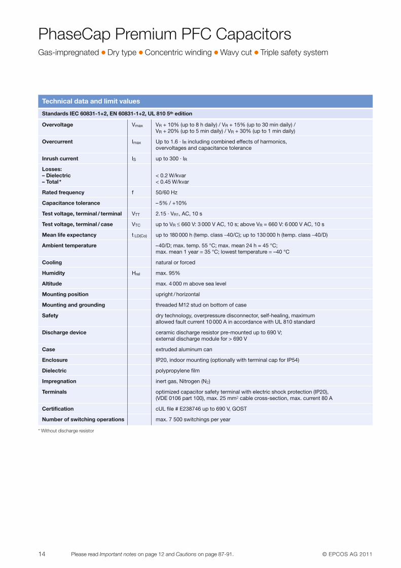
Technical data and limit values
Standards IEC 60831-1+2, EN 60831-1+2, UL 810 5th edition
Overvoltage Vmax VR + 10% (up to 8 h daily) / VR + 15% (up to 30 min daily) /VR + 20% (up to 5 min daily) / VR + 30% (up to 1 min daily)
Overcurrent Imax Up to 1.6 · IR including combined effects of harmonics, overvoltages and capacitance tolerance
Inrush current IS up to 300 · IR
Losses:– Dielectric < 0.2 W/kvar– Total* < 0.45 W/kvar
Rated frequency f 50/60 Hz
Capacitance tolerance – 5% / +10%
Test voltage, terminal / terminal VTT 2.15 · VR1, AC, 10 s
Test voltage, terminal / case VTC up to VR ≤ 660 V: 3 000 V AC, 10 s; above VR = 660 V: 6 000 V AC, 10 s
Mean life expectancy t LD(Co) up to 180 000 h (temp. class –40/C); up to 130 000 h (temp. class –40/D)
Ambient temperature –40/D; max. temp. 55 °C; max. mean 24 h = 45 °C; max. mean 1 year = 35 °C; lowest temperature = –40 °C
Cooling natural or forced
Humidity Hrel max. 95%
Altitude max. 4 000 m above sea level
Mounting position upright / horizontal
Mounting and grounding threaded M12 stud on bottom of case
Safety dry technology, overpressure disconnector, self-healing, maximum allowed fault current 10 000 A in accordance with UL 810 standard
Discharge device ceramic discharge resistor pre-mounted up to 690 V; external discharge module for > 690 V
Case extruded aluminum can
Enclosure IP20, indoor mounting (optionally with terminal cap for IP54)
Dielectric polypropylene film
Impregnation inert gas, Nitrogen (N2)
Terminals optimized capacitor safety terminal with electric shock protection (IP20), (VDE 0106 part 100), max. 25 mm2 cable cross-section, max. current 80 A
Certification cUL file # E238746 up to 690 V, GOST
Number of switching operations max. 7 500 switchings per year
* Without discharge resistor
© EPCOS AG 2011 15Please read Important notes on page 12 and Cautions on page 87-91.
PhaseCap Premium PFC CapacitorsGas-impregnated � Dry type � Concentric winding � Wavy cut � Triple safety system
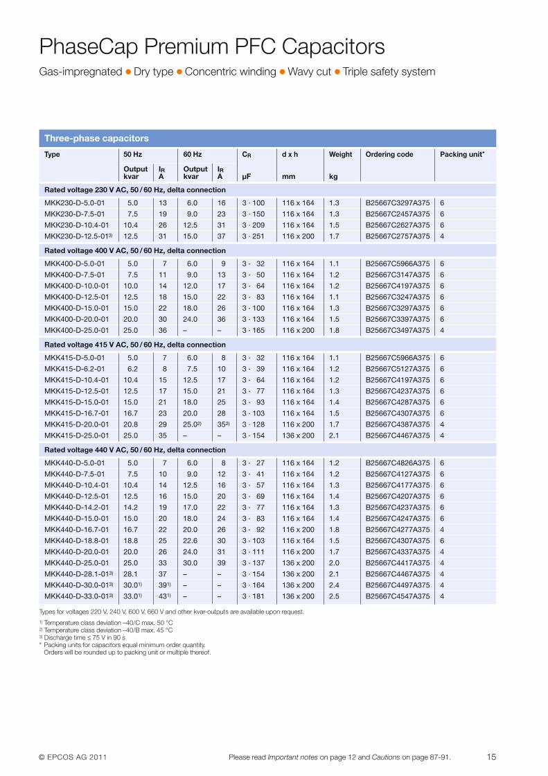
Three-phase capacitors
Types for voltages 220 V, 240 V, 600 V, 660 V and other kvar-outputs are available upon request.1) Temperature class deviation –40/C max. 50 °C2) Temperature class deviation –40/B max. 45 °C3) Discharge time ≤ 75 V in 90 s* Packing units for capacitors equal minimum order quantity.
Orders will be rounded up to packing unit or multiple thereof.
Type 50 Hz 60 Hz CR d x h Weight Ordering code Packing unit*
Output IR Output IRkvar A kvar A µF mm kg
Rated voltage 230 V AC, 50 / 60 Hz, delta connection
MKK230-D-5.0-01 5.0 13 6.0 16 3 · 100 116 x 164 1.3 B25667C3297A375 6
MKK230-D-7.5-01 7.5 19 9.0 23 3 · 150 116 x 164 1.3 B25667C2457A375 6
MKK230-D-10.4-01 10.4 26 12.5 31 3 · 209 116 x 164 1.5 B25667C2627A375 6
MKK230-D-12.5-013) 12.5 31 15.0 37 3 · 251 116 x 200 1.7 B25667C2757A375 4
Rated voltage 400 V AC, 50 / 60 Hz, delta connection
MKK400-D-5.0-01 5.0 7 6.0 9 3 · 32 116 x 164 1.1 B25667C5966A375 6
MKK400-D-7.5-01 7.5 11 9.0 13 3 · 50 116 x 164 1.2 B25667C3147A375 6
MKK400-D-10.0-01 10.0 14 12.0 17 3 · 64 116 x 164 1.2 B25667C4197A375 6
MKK400-D-12.5-01 12.5 18 15.0 22 3 · 83 116 x 164 1.1 B25667C3247A375 6
MKK400-D-15.0-01 15.0 22 18.0 26 3 · 100 116 x 164 1.3 B25667C3297A375 6
MKK400-D-20.0-01 20.0 30 24.0 36 3 · 133 116 x 164 1.5 B25667C3397A375 6
MKK400-D-25.0-01 25.0 36 – – 3 · 165 116 x 200 1.8 B25667C3497A375 4
Rated voltage 415 V AC, 50 / 60 Hz, delta connection
MKK415-D-5.0-01 5.0 7 6.0 8 3 · 32 116 x 164 1.1 B25667C5966A375 6
MKK415-D-6.2-01 6.2 8 7.5 10 3 · 39 116 x 164 1.2 B25667C5127A375 6
MKK415-D-10.4-01 10.4 15 12.5 17 3 · 64 116 x 164 1.2 B25667C4197A375 6
MKK415-D-12.5-01 12.5 17 15.0 21 3 · 77 116 x 164 1.3 B25667C4237A375 6
MKK415-D-15.0-01 15.0 21 18.0 25 3 · 93 116 x 164 1.4 B25667C4287A375 6
MKK415-D-16.7-01 16.7 23 20.0 28 3 · 103 116 x 164 1.5 B25667C4307A375 6
MKK415-D-20.0-01 20.8 29 25.02) 352) 3 · 128 116 x 200 1.7 B25667C4387A375 4
MKK415-D-25.0-01 25.0 35 – – 3 · 154 136 x 200 2.1 B25667C4467A375 4
Rated voltage 440 V AC, 50 / 60 Hz, delta connection
MKK440-D-5.0-01 5.0 7 6.0 8 3 · 27 116 x 164 1.2 B25667C4826A375 6
MKK440-D-7.5-01 7.5 10 9.0 12 3 · 41 116 x 164 1.2 B25667C4127A375 6
MKK440-D-10.4-01 10.4 14 12.5 16 3 · 57 116 x 164 1.3 B25667C4177A375 6
MKK440-D-12.5-01 12.5 16 15.0 20 3 · 69 116 x 164 1.4 B25667C4207A375 6
MKK440-D-14.2-01 14.2 19 17.0 22 3 · 77 116 x 164 1.3 B25667C4237A375 6
MKK440-D-15.0-01 15.0 20 18.0 24 3 · 83 116 x 164 1.4 B25667C4247A375 6
MKK440-D-16.7-01 16.7 22 20.0 26 3 · 92 116 x 200 1.8 B25667C4277A375 4
MKK440-D-18.8-01 18.8 25 22.6 30 3 · 103 116 x 164 1.5 B25667C4307A375 6
MKK440-D-20.0-01 20.0 26 24.0 31 3 · 111 116 x 200 1.7 B25667C4337A375 4
MKK440-D-25.0-01 25.0 33 30.0 39 3 · 137 136 x 200 2.0 B25667C4417A375 4
MKK440-D-28.1-013) 28.1 37 – – 3 · 154 136 x 200 2.1 B25667C4467A375 4
MKK440-D-30.0-013) 30.01) 391) – – 3 · 164 136 x 200 2.4 B25667C4497A375 4
MKK440-D-33.0-013) 33.01) 431) – – 3 · 181 136 x 200 2.5 B25667C4547A375 4
16 © EPCOS AG 2011Please read Important notes on page 12 and Cautions on page 87-91.
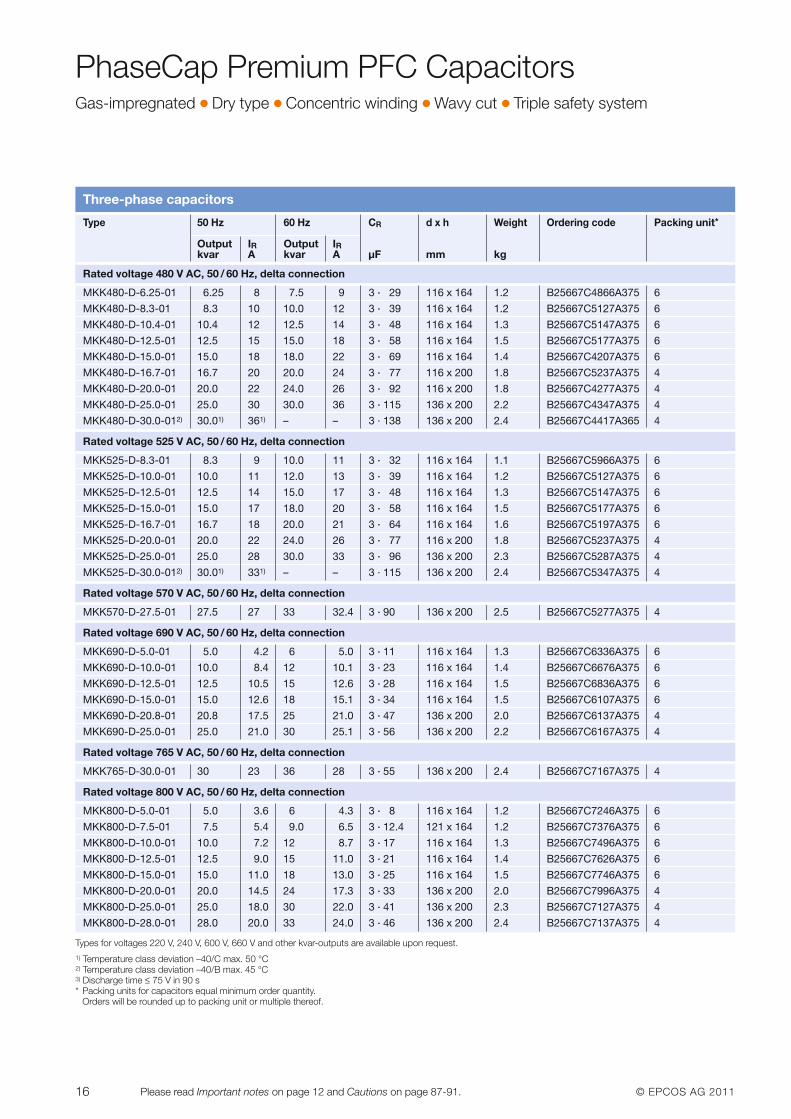
Three-phase capacitors
Type 50 Hz 60 Hz CR d x h Weight Ordering code Packing unit*
Output IR Output IRkvar A kvar A µF mm kg
Rated voltage 480 V AC, 50 / 60 Hz, delta connection
MKK480-D-6.25-01 6.25 8 7.5 9 3 · 29 116 x 164 1.2 B25667C4866A375 6
MKK480-D-8.3-01 8.3 10 10.0 12 3 · 39 116 x 164 1.2 B25667C5127A375 6
MKK480-D-10.4-01 10.4 12 12.5 14 3 · 48 116 x 164 1.3 B25667C5147A375 6
MKK480-D-12.5-01 12.5 15 15.0 18 3 · 58 116 x 164 1.5 B25667C5177A375 6
MKK480-D-15.0-01 15.0 18 18.0 22 3 · 69 116 x 164 1.4 B25667C4207A375 6
MKK480-D-16.7-01 16.7 20 20.0 24 3 · 77 116 x 200 1.8 B25667C5237A375 4
MKK480-D-20.0-01 20.0 22 24.0 26 3 · 92 116 x 200 1.8 B25667C4277A375 4
MKK480-D-25.0-01 25.0 30 30.0 36 3 · 115 136 x 200 2.2 B25667C4347A375 4
MKK480-D-30.0-012) 30.01) 361) – – 3 · 138 136 x 200 2.4 B25667C4417A365 4
Rated voltage 525 V AC, 50 / 60 Hz, delta connection
MKK525-D-8.3-01 8.3 9 10.0 11 3 · 32 116 x 164 1.1 B25667C5966A375 6
MKK525-D-10.0-01 10.0 11 12.0 13 3 · 39 116 x 164 1.2 B25667C5127A375 6
MKK525-D-12.5-01 12.5 14 15.0 17 3 · 48 116 x 164 1.3 B25667C5147A375 6
MKK525-D-15.0-01 15.0 17 18.0 20 3 · 58 116 x 164 1.5 B25667C5177A375 6
MKK525-D-16.7-01 16.7 18 20.0 21 3 · 64 116 x 164 1.6 B25667C5197A375 6
MKK525-D-20.0-01 20.0 22 24.0 26 3 · 77 116 x 200 1.8 B25667C5237A375 4
MKK525-D-25.0-01 25.0 28 30.0 33 3 · 96 136 x 200 2.3 B25667C5287A375 4
MKK525-D-30.0-012) 30.01) 331) – – 3 · 115 136 x 200 2.4 B25667C5347A375 4
Rated voltage 570 V AC, 50 / 60 Hz, delta connection
MKK570-D-27.5-01 27.5 27 33 32.4 3 · 90 136 x 200 2.5 B25667C5277A375 4
Rated voltage 690 V AC, 50 / 60 Hz, delta connection
MKK690-D-5.0-01 5.0 4.2 6 5.0 3 · 11 116 x 164 1.3 B25667C6336A375 6
MKK690-D-10.0-01 10.0 8.4 12 10.1 3 · 23 116 x 164 1.4 B25667C6676A375 6
MKK690-D-12.5-01 12.5 10.5 15 12.6 3 · 28 116 x 164 1.5 B25667C6836A375 6
MKK690-D-15.0-01 15.0 12.6 18 15.1 3 · 34 116 x 164 1.5 B25667C6107A375 6
MKK690-D-20.8-01 20.8 17.5 25 21.0 3 · 47 136 x 200 2.0 B25667C6137A375 4
MKK690-D-25.0-01 25.0 21.0 30 25.1 3 · 56 136 x 200 2.2 B25667C6167A375 4
Rated voltage 765 V AC, 50 / 60 Hz, delta connection
MKK765-D-30.0-01 30 23 36 28 3 · 55 136 x 200 2.4 B25667C7167A375 4
Rated voltage 800 V AC, 50 / 60 Hz, delta connection
MKK800-D-5.0-01 5.0 3.6 6 4.3 3 · 8 116 x 164 1.2 B25667C7246A375 6
MKK800-D-7.5-01 7.5 5.4 9.0 6.5 3 · 12.4 121 x 164 1.2 B25667C7376A375 6
MKK800-D-10.0-01 10.0 7.2 12 8.7 3 · 17 116 x 164 1.3 B25667C7496A375 6
MKK800-D-12.5-01 12.5 9.0 15 11.0 3 · 21 116 x 164 1.4 B25667C7626A375 6
MKK800-D-15.0-01 15.0 11.0 18 13.0 3 · 25 116 x 164 1.5 B25667C7746A375 6
MKK800-D-20.0-01 20.0 14.5 24 17.3 3 · 33 136 x 200 2.0 B25667C7996A375 4
MKK800-D-25.0-01 25.0 18.0 30 22.0 3 · 41 136 x 200 2.3 B25667C7127A375 4
MKK800-D-28.0-01 28.0 20.0 33 24.0 3 · 46 136 x 200 2.4 B25667C7137A375 4
PhaseCap Premium PFC CapacitorsGas-impregnated � Dry type � Concentric winding � Wavy cut � Triple safety system
Types for voltages 220 V, 240 V, 600 V, 660 V and other kvar-outputs are available upon request.1) Temperature class deviation –40/C max. 50 °C2) Temperature class deviation –40/B max. 45 °C3) Discharge time ≤ 75 V in 90 s* Packing units for capacitors equal minimum order quantity.
Orders will be rounded up to packing unit or multiple thereof.
© EPCOS AG 2011 17Please read Important notes on page 12 and Cautions on page 87-91.
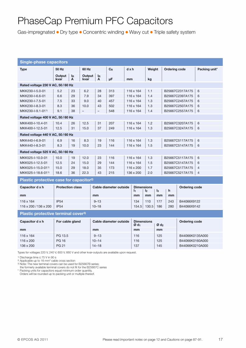
Single-phase capacitors
Type 50 Hz 60 Hz CR d x h Weight Ordering code Packing unit*
Output IR Output IRkvar A kvar A µF mm kg
Rated voltage 230 V AC, 50 / 60 Hz
MKK230-I-5.0-01 5.2 23 6.2 28 313 116 x 164 1.1 B25667C2317A175 6
MKK230-I-6.6-01 6.6 29 7.9 34 397 116 x 164 1.4 B25667C2397A175 6
MKK230-I-7.5-01 7.5 33 9.0 40 457 116 x 164 1.3 B25667C2457A175 6
MKK230-I-8.3-01 8.3 36 10.0 43 502 116 x 164 1.3 B25667C2507A175 6
MKK230-I-9.1-011) 9.1 38 – – 548 116 x 164 1.4 B25667C2557A175 6
Rated voltage 400 V AC, 50 / 60 Hz
MKK400-I-10.4-01 10.4 26 12.5 31 207 116 x 164 1.2 B25667C3207A175 6
MKK400-I-12.5-01 12.5 31 15.0 37 249 116 x 164 1.3 B25667C3247A175 6
Rated voltage 440 V AC, 50 / 60 Hz
MKK440-I-6.9-01 6.9 16 8.3 19 116 116 x 164 1.3 B25667C5117A175 6
MKK440-I-8.3-01 8.3 19 10.0 23 144 116 x 164 1.5 B25667C5147A175 6
Rated voltage 525 V AC, 50 / 60 Hz
MKK525-I-10.0-01 10.0 19 12.0 23 116 116 x 164 1.3 B25667C5117A175 6
MKK525-I-12.5-01 12.5 24 15.0 29 144 116 x 164 1.5 B25667C5147A175 6
MKK525-I-15.0-011) 15.0 29 18.0 35 173 116 x 200 1.7 B25667C5177A175 4
MKK525-I-18.6-011) 18.6 36 22.3 43 215 136 x 200 2.0 B25667C5217A175 4
Plastic protective case for capacitor2)
Capacitor d x h Protection class Cable diameter outside Dimensions Ordering codel1 l2 l3 h
mm mm mm mm mm mm
116 x 164 IP54 9–13 134 110 177 243 B44066X9122
116 x 200 / 136 x 200 IP54 10–18 154.5 130.5 186 280 B44066X9142
Plastic protective terminal cover3)
Capacitor d x h For cable gland Cable diameter outside Dimensions Ordering codeØ d1 Ø d2
mm mm mm mm
116 x 164 PG 13.5 9–13 116 125 B44066K0135A000
116 x 200 PG 16 10–14 116 125 B44066K0160A000
136 x 200 PG 21 14–18 137 145 B44066K0210A000
Types for voltages 220 V, 240 V, 600 V, 660 V and other kvar-outputs are available upon request.1) Discharge time ≤ 75 V in 90 s2) Applicable up to 16 mm2 cable cross section3) Note: The new terminal covers can be used for B25667B series;
the formerly available terminal covers do not fit for the B25667C series* Packing units for capacitors equal minimum order quantity.
Orders will be rounded up to packing unit or multiple thereof.
PhaseCap Premium PFC CapacitorsGas-impregnated � Dry type � Concentric winding � Wavy cut � Triple safety system
18 © EPCOS AG 2011Please read Important notes on page 12 and Cautions on page 87-91.
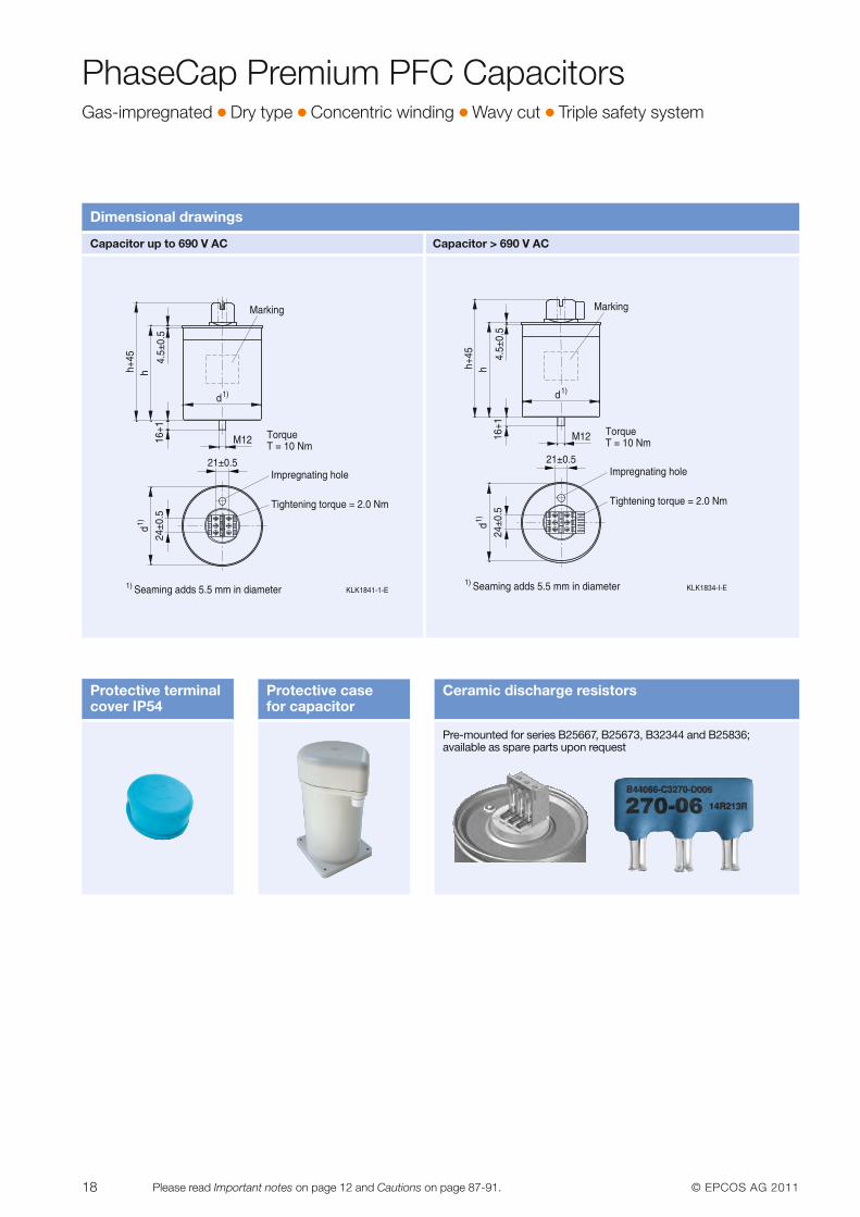
PhaseCap Premium PFC CapacitorsGas-impregnated � Dry type � Concentric winding � Wavy cut � Triple safety system
Dimensional drawings
Capacitor up to 690 V AC Capacitor > 690 V AC
Protective terminal cover IP54
Protective case for capacitor
Ceramic discharge resistors
Pre-mounted for series B25667, B25673, B32344 and B25836;available as spare parts upon request
© EPCOS AG 2011 19Please read Important notes on page 12 and Cautions on page 87-91.
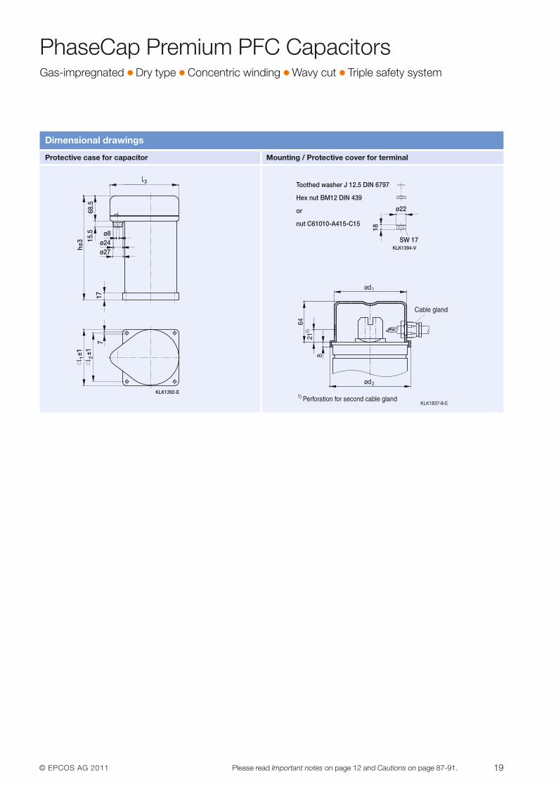
PhaseCap Premium PFC CapacitorsGas-impregnated � Dry type � Concentric winding � Wavy cut � Triple safety system
Dimensional drawings
KLK1394-V
Hex nut BM12 DIN 439
or
nut C61010-A415-C15
Toothed washer J 12.5 DIN 6797
18
SW 17
ø22
KLK1392-E
68.5
15.5 ø8
ø24ø27
h±3
±1 ±1
177
1 2
3
Protective case for capacitor Mounting / Protective cover for terminal
20 © EPCOS AG 2011Please read Important notes on page 12 and Cautions on page 87-91.
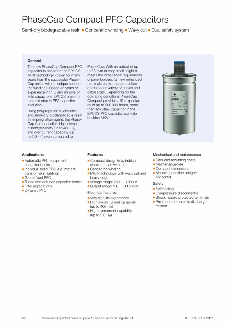
PhaseCap Compact PFC CapacitorsSemi-dry biodegradable resin � Concentric winding � Wavy cut � Dual safety system
Applications
� Automatic PFC equipment, capacitor banks
� Individual fixed PFC (e.g. motors,transformers, lighting)
� Group fixed PFC� Tuned and detuned capacitor banks� Filter applications� Dynamic PFC
Features
� Compact design in cylindrical aluminum can with stud
� Concentric winding � MKK-technology with wavy cut and
heavy edge � Voltage range: 230 … 1000 V� Output range: 5.0 … 33.0 kvar
Electrical features� Very high life expectancy � High inrush current capability
(up to 400 · IR) � High overcurrent capability
(up to 2.0 · IR)
Mechanical and maintenance� Reduced mounting costs � Maintenance-free � Compact dimensions � Mounting position upright/
horizontal
Safety� Self healing � Overpressure disconnector � Shock hazard protected terminals � Pre-mounted ceramic discharge
resistor
General
The new PhaseCap Compact PFCcapacitor is based on the EPCOSMKK technology known for manyyears from the successful Phase-Cap series with its unique concen-tric windings. Based on years of experience in PFC and millions ofsold capacitors, EPCOS presentsthe next step in PFC capacitor evolution.
Using polypropylene as dielectricand semi-dry biodegradable resinas impregnation agent, the Phase-Cap Compact offers higher inrushcurrent capability (up to 400 · IR) and over current capability (up to 2.0 · IR) even compared to
PhaseCap. With an output of up to 33 kvar at very small height itmeets the dimensional requirementsof panel builders. Its new enhancedterminals permit the connection of a broader variety of cables andcable sizes. Depending on the operating conditions PhaseCapCompact provides a life expectan-cy of up to 200 000 hours, morethan any other capacitor in the EPCOS PFC capacitor portfoliobesides MKV.
© EPCOS AG 2011 21Please read Important notes on page 12 and Cautions on page 87-91.
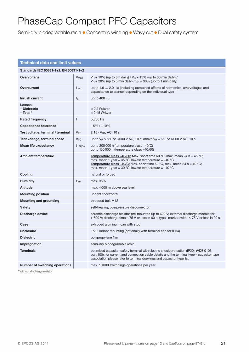
PhaseCap Compact PFC CapacitorsSemi-dry biodegradable resin � Concentric winding � Wavy cut � Dual safety system
Technical data and limit values
Standards IEC 60831-1+2, EN 60831-1+2
Overvoltage Vmax VR + 10% (up to 8 h daily) / VR + 15% (up to 30 min daily) / VR + 20% (up to 5 min daily) / VR + 30% (up to 1 min daily)
Overcurrent Imax up to 1.6 … 2.0 · IR (including combined effects of harmonics, overvoltages and capacitance tolerance) depending on the individual type
Inrush current IS up to 400 · IR
Losses:– Dielectric < 0.2 W/kvar– Total* < 0.45 W/kvar
Rated frequency f 50/60 Hz
Capacitance tolerance – 5% / +10%
Test voltage, terminal / terminal VTT 2.15 · VR1, AC, 10 s
Test voltage, terminal / case VTC up to VR ≤ 660 V: 3 000 V AC, 10 s; above VR = 660 V: 6 000 V AC, 10 s
Mean life expectancy t LD(Co) up to 200 000 h (temperature class –40/C) up to 150 000 h (temperature class –40/60)
Ambient temperature Temperature class –40/60: Max. short time 60 °C, max. mean 24 h = 45 °C; max. mean 1 year = 35 °C; lowest temperature = –40 °CTemperature class –40/C: Max. short time 50 °C, max. mean 24 h = 40 °C; max. mean 1 year = 30 °C; lowest temperature = –40 °C
Cooling natural or forced
Humidity Hrel max. 95%
Altitude max. 4 000 m above sea level
Mounting position upright / horizontal
Mounting and grounding threaded bolt M12
Safety self-healing, overpressure disconnector
Discharge device ceramic discharge resistor pre-mounted up to 690 V; external discharge module for > 690 V; discharge time ≤ 75 V or less in 60 s; types marked with1) ≤ 75 V or less in 90 s
Case extruded aluminum can with stud
Enclosure IP20, indoor mounting (optionally with terminal cap for IP54)
Dielectric polypropylene film
Impregnation semi-dry biodegradable resin
Terminals optimized capacitor safety terminal with electric shock protection (IP20), (VDE 0106 part 100), for current and connection cable details and the terminal type – capacitor typeassociation please refer to terminal drawings and capacitor type list
Number of switching operations max. 10 000 switchings operations per year
* Without discharge resistor
22 © EPCOS AG 2011Please read Important notes on page 12 and Cautions on page 87-91.
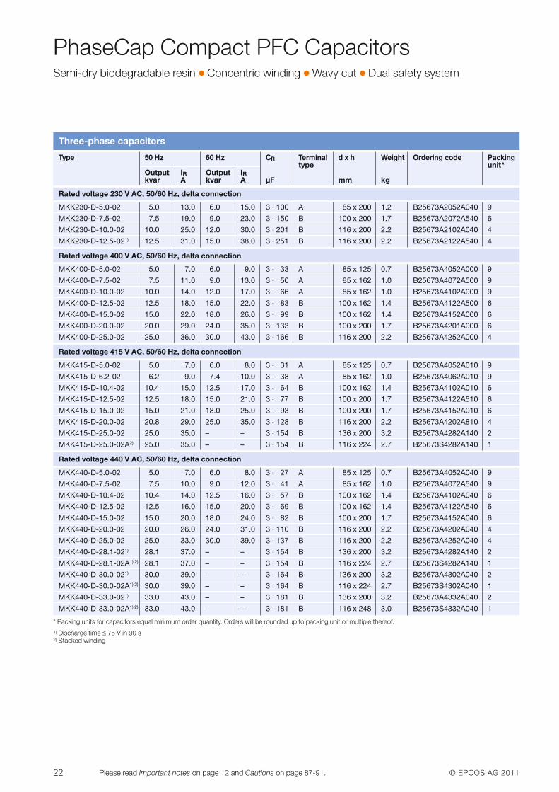
PhaseCap Compact PFC CapacitorsSemi-dry biodegradable resin � Concentric winding � Wavy cut � Dual safety system
Three-phase capacitors
Type 50 Hz 60 Hz CR Terminal d x h Weight Ordering code Packingtype unit*
Output IR Output IRkvar A kvar A µF mm kg
Rated voltage 230 V AC, 50/60 Hz, delta connection
MKK230-D-5.0-02 5.0 13.0 6.0 15.0 3 · 100 A 85 x 200 1.2 B25673A2052A040 9
MKK230-D-7.5-02 7.5 19.0 9.0 23.0 3 · 150 B 100 x 200 1.7 B25673A2072A540 6
MKK230-D-10.0-02 10.0 25.0 12.0 30.0 3 · 201 B 116 x 200 2.2 B25673A2102A040 4
MKK230-D-12.5-021) 12.5 31.0 15.0 38.0 3 · 251 B 116 x 200 2.2 B25673A2122A540 4
Rated voltage 400 V AC, 50/60 Hz, delta connection
MKK400-D-5.0-02 5.0 7.0 6.0 9.0 3 · 33 A 85 x 125 0.7 B25673A4052A000 9
MKK400-D-7.5-02 7.5 11.0 9.0 13.0 3 · 50 A 85 x 162 1.0 B25673A4072A500 9
MKK400-D-10.0-02 10.0 14.0 12.0 17.0 3 · 66 A 85 x 162 1.0 B25673A4102A000 9
MKK400-D-12.5-02 12.5 18.0 15.0 22.0 3 · 83 B 100 x 162 1.4 B25673A4122A500 6
MKK400-D-15.0-02 15.0 22.0 18.0 26.0 3 · 99 B 100 x 162 1.4 B25673A4152A000 6
MKK400-D-20.0-02 20.0 29.0 24.0 35.0 3 · 133 B 100 x 200 1.7 B25673A4201A000 6
MKK400-D-25.0-02 25.0 36.0 30.0 43.0 3 · 166 B 116 x 200 2.2 B25673A4252A000 4
Rated voltage 415 V AC, 50/60 Hz, delta connection
MKK415-D-5.0-02 5.0 7.0 6.0 8.0 3 · 31 A 85 x 125 0.7 B25673A4052A010 9
MKK415-D-6.2-02 6.2 9.0 7.4 10.0 3 · 38 A 85 x 162 1.0 B25673A4062A010 9
MKK415-D-10.4-02 10.4 15.0 12.5 17.0 3 · 64 B 100 x 162 1.4 B25673A4102A010 6
MKK415-D-12.5-02 12.5 18.0 15.0 21.0 3 · 77 B 100 x 200 1.7 B25673A4122A510 6
MKK415-D-15.0-02 15.0 21.0 18.0 25.0 3 · 93 B 100 x 200 1.7 B25673A4152A010 6
MKK415-D-20.0-02 20.8 29.0 25.0 35.0 3 · 128 B 116 x 200 2.2 B25673A4202A810 4
MKK415-D-25.0-02 25.0 35.0 – – 3 · 154 B 136 x 200 3.2 B25673A4282A140 2
MKK415-D-25.0-02A2) 25.0 35.0 – – 3 · 154 B 116 x 224 2.7 B25673S4282A140 1
Rated voltage 440 V AC, 50/60 Hz, delta connection
MKK440-D-5.0-02 5.0 7.0 6.0 8.0 3 · 27 A 85 x 125 0.7 B25673A4052A040 9
MKK440-D-7.5-02 7.5 10.0 9.0 12.0 3 · 41 A 85 x 162 1.0 B25673A4072A540 9
MKK440-D-10.4-02 10.4 14.0 12.5 16.0 3 · 57 B 100 x 162 1.4 B25673A4102A040 6
MKK440-D-12.5-02 12.5 16.0 15.0 20.0 3 · 69 B 100 x 162 1.4 B25673A4122A540 6
MKK440-D-15.0-02 15.0 20.0 18.0 24.0 3 · 82 B 100 x 200 1.7 B25673A4152A040 6
MKK440-D-20.0-02 20.0 26.0 24.0 31.0 3 · 110 B 116 x 200 2.2 B25673A4202A040 4
MKK440-D-25.0-02 25.0 33.0 30.0 39.0 3 · 137 B 116 x 200 2.2 B25673A4252A040 4
MKK440-D-28.1-021) 28.1 37.0 – – 3 · 154 B 136 x 200 3.2 B25673A4282A140 2
MKK440-D-28.1-02A1) 2) 28.1 37.0 – – 3 · 154 B 116 x 224 2.7 B25673S4282A140 1
MKK440-D-30.0-021) 30.0 39.0 – – 3 · 164 B 136 x 200 3.2 B25673A4302A040 2
MKK440-D-30.0-02A1) 2) 30.0 39.0 – – 3 · 164 B 116 x 224 2.7 B25673S4302A040 1
MKK440-D-33.0-021) 33.0 43.0 – – 3 · 181 B 136 x 200 3.2 B25673A4332A040 2
MKK440-D-33.0-02A1) 2) 33.0 43.0 – – 3 · 181 B 116 x 248 3.0 B25673S4332A040 1
* Packing units for capacitors equal minimum order quantity. Orders will be rounded up to packing unit or multiple thereof.1) Discharge time ≤ 75 V in 90 s2) Stacked winding
© EPCOS AG 2011 23Please read Important notes on page 12 and Cautions on page 87-91.
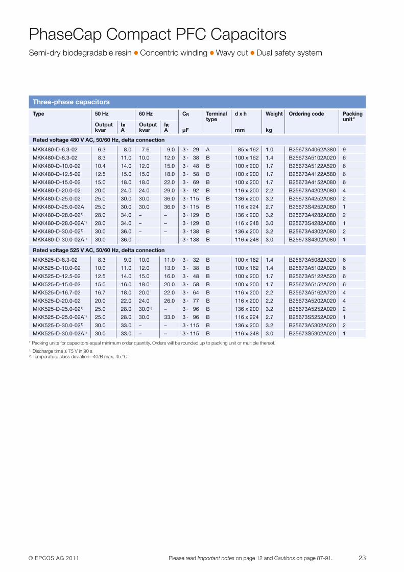
PhaseCap Compact PFC CapacitorsSemi-dry biodegradable resin � Concentric winding � Wavy cut � Dual safety system
Three-phase capacitors
Type 50 Hz 60 Hz CR Terminal d x h Weight Ordering code Packingtype unit*
Output IR Output IRkvar A kvar A µF mm kg
* Packing units for capacitors equal minimum order quantity. Orders will be rounded up to packing unit or multiple thereof.1) Discharge time ≤ 75 V in 90 s2) Temperature class deviation –40/B max. 45 °C
Rated voltage 480 V AC, 50/60 Hz, delta connection
MKK480-D-6.3-02 6.3 8.0 7.6 9.0 3 · 29 A 85 x 162 1.0 B25673A4062A380 9
MKK480-D-8.3-02 8.3 11.0 10.0 12.0 3 · 38 B 100 x 162 1.4 B25673A5102A020 6
MKK480-D-10.0-02 10.4 14.0 12.0 15.0 3 · 48 B 100 x 200 1.7 B25673A5122A520 6
MKK480-D-12.5-02 12.5 15.0 15.0 18.0 3 · 58 B 100 x 200 1.7 B25673A4122A580 6
MKK480-D-15.0-02 15.0 18.0 18.0 22.0 3 · 69 B 100 x 200 1.7 B25673A4152A080 6
MKK480-D-20.0-02 20.0 24.0 24.0 29.0 3 · 92 B 116 x 200 2.2 B25673A4202A080 4
MKK480-D-25.0-02 25.0 30.0 30.0 36.0 3 · 115 B 136 x 200 3.2 B25673A4252A080 2
MKK480-D-25.0-02A 25.0 30.0 30.0 36.0 3 · 115 B 116 x 224 2.7 B25673S4252A080 1
MKK480-D-28.0-021) 28.0 34.0 – – 3 · 129 B 136 x 200 3.2 B25673A4282A080 2
MKK480-D-28.0-02A1) 28.0 34.0 – – 3 · 129 B 116 x 248 3.0 B25673S4282A080 1
MKK480-D-30.0-021) 30.0 36.0 – – 3 · 138 B 136 x 200 3.2 B25673A4302A080 2
MKK480-D-30.0-02A1) 30.0 36.0 – – 3 · 138 B 116 x 248 3.0 B25673S4302A080 1
Rated voltage 525 V AC, 50/60 Hz, delta connection
MKK525-D-8.3-02 8.3 9.0 10.0 11.0 3 · 32 B 100 x 162 1.4 B25673A5082A320 6
MKK525-D-10.0-02 10.0 11.0 12.0 13.0 3 · 38 B 100 x 162 1.4 B25673A5102A020 6
MKK525-D-12.5-02 12.5 14.0 15.0 16.0 3 · 48 B 100 x 200 1.7 B25673A5122A520 6
MKK525-D-15.0-02 15.0 16.0 18.0 20.0 3 · 58 B 100 x 200 1.7 B25673A5152A020 6
MKK525-D-16.7-02 16.7 18.0 20.0 22.0 3 · 64 B 116 x 200 2.2 B25673A5162A720 4
MKK525-D-20.0-02 20.0 22.0 24.0 26.0 3 · 77 B 116 x 200 2.2 B25673A5202A020 4
MKK525-D-25.0-021) 25.0 28.0 30.02) – 3 · 96 B 136 x 200 3.2 B25673A5252A020 2
MKK525-D-25.0-02A1) 25.0 28.0 30.0 33.0 3 · 96 B 116 x 224 2.7 B25673S5252A020 1
MKK525-D-30.0-021) 30.0 33.0 – – 3 · 115 B 136 x 200 3.2 B25673A5302A020 2
MKK525-D-30.0-02A1) 30.0 33.0 – – 3 · 115 B 116 x 248 3.0 B25673S5302A020 1
24 © EPCOS AG 2011Please read Important notes on page 12 and Cautions on page 87-91.
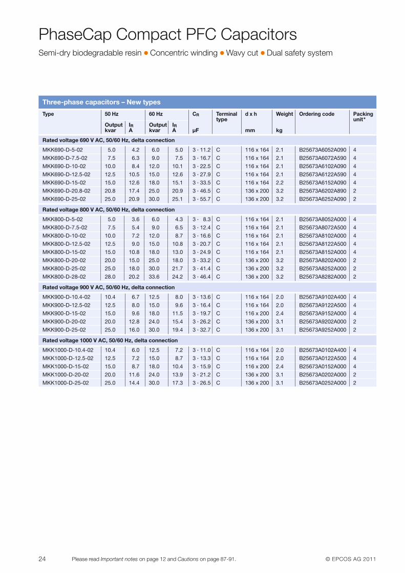
PhaseCap Compact PFC CapacitorsSemi-dry biodegradable resin � Concentric winding � Wavy cut � Dual safety system
Three-phase capacitors – New types
Type 50 Hz 60 Hz CR Terminal d x h Weight Ordering code Packingtype unit*
Output IR Output IRkvar A kvar A µF mm kg
Rated voltage 690 V AC, 50/60 Hz, delta connection
MKK690-D-5-02 5.0 4.2 6.0 5.0 3 · 11.2 C 116 x 164 2.1 B25673A6052A090 4
MKK690-D-7.5-02 7.5 6.3 9.0 7.5 3 · 16.7 C 116 x 164 2.1 B25673A6072A590 4
MKK690-D-10-02 10.0 8.4 12.0 10.1 3 · 22.5 C 116 x 164 2.1 B25673A6102A090 4
MKK690-D-12.5-02 12.5 10.5 15.0 12.6 3 · 27.9 C 116 x 164 2.1 B25673A6122A590 4
MKK690-D-15-02 15.0 12.6 18.0 15.1 3 · 33.5 C 116 x 164 2.2 B25673A6152A090 4
MKK690-D-20.8-02 20.8 17.4 25.0 20.9 3 · 46.5 C 136 x 200 3.2 B25673A6202A890 2
MKK690-D-25-02 25.0 20.9 30.0 25.1 3 · 55.7 C 136 x 200 3.2 B25673A6252A090 2
Rated voltage 800 V AC, 50/60 Hz, delta connection
MKK800-D-5-02 5.0 3.6 6.0 4.3 3 · 8.3 C 116 x 164 2.1 B25673A8052A000 4
MKK800-D-7.5-02 7.5 5.4 9.0 6.5 3 · 12.4 C 116 x 164 2.1 B25673A8072A500 4
MKK800-D-10-02 10.0 7.2 12.0 8.7 3 · 16.6 C 116 x 164 2.1 B25673A8102A000 4
MKK800-D-12.5-02 12.5 9.0 15.0 10.8 3 · 20.7 C 116 x 164 2.1 B25673A8122A500 4
MKK800-D-15-02 15.0 10.8 18.0 13.0 3 · 24.9 C 116 x 164 2.1 B25673A8152A000 4
MKK800-D-20-02 20.0 15.0 25.0 18.0 3 · 33.2 C 136 x 200 3.2 B25673A8202A000 2
MKK800-D-25-02 25.0 18.0 30.0 21.7 3 · 41.4 C 136 x 200 3.2 B25673A8252A000 2
MKK800-D-28-02 28.0 20.2 33.6 24.2 3 · 46.4 C 136 x 200 3.2 B25673A8282A000 2
Rated voltage 900 V AC, 50/60 Hz, delta connection
MKK900-D-10.4-02 10.4 6.7 12.5 8.0 3 · 13.6 C 116 x 164 2.0 B25673A9102A400 4
MKK900-D-12.5-02 12.5 8.0 15.0 9.6 3 · 16.4 C 116 x 164 2.0 B25673A9122A500 4
MKK900-D-15-02 15.0 9.6 18.0 11.5 3 · 19.7 C 116 x 200 2.4 B25673A9152A000 4
MKK900-D-20-02 20.0 12.8 24.0 15.4 3 · 26.2 C 136 x 200 3.1 B25673A9202A000 2
MKK900-D-25-02 25.0 16.0 30.0 19.4 3 · 32.7 C 136 x 200 3.1 B25673A9252A000 2
Rated voltage 1000 V AC, 50/60 Hz, delta connection
MKK1000-D-10.4-02 10.4 6.0 12.5 7.2 3 · 11.0 C 116 x 164 2.0 B25673A0102A400 4
MKK1000-D-12.5-02 12.5 7.2 15.0 8.7 3 · 13.3 C 116 x 164 2.0 B25673A0122A500 4
MKK1000-D-15-02 15.0 8.7 18.0 10.4 3 · 15.9 C 116 x 200 2.4 B25673A0152A000 4
MKK1000-D-20-02 20.0 11.6 24.0 13.9 3 · 21.2 C 136 x 200 3.1 B25673A0202A000 2
MKK1000-D-25-02 25.0 14.4 30.0 17.3 3 · 26.5 C 136 x 200 3.1 B25673A0252A000 2
© EPCOS AG 2011 25Please read Important notes on page 12 and Cautions on page 87-91.
PhaseCap Compact PFC CapacitorsSemi-dry biodegradable resin � Concentric winding � Wavy cut � Dual safety system
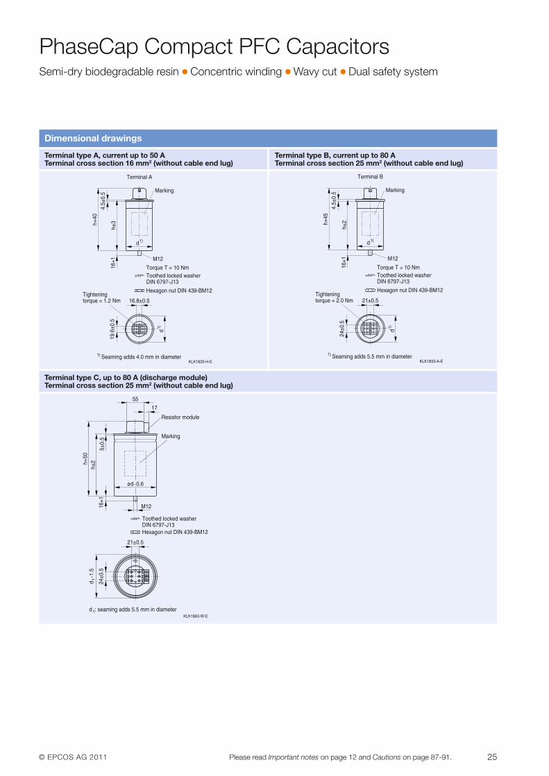
Dimensional drawings
Terminal type A, current up to 50 A Terminal type B, current up to 80 ATerminal cross section 16 mm2 (without cable end lug) Terminal cross section 25 mm2 (without cable end lug)
Terminal type C, up to 80 A (discharge module)Terminal cross section 25 mm2 (without cable end lug)
26 © EPCOS AG 2011Please read Important notes on page 12 and Cautions on page 87-91.
PhaseCap HD PFC CapacitorsHigh density type � Up to 60 kvar � Gas-impregnated � Wavy cut � Triple safety system
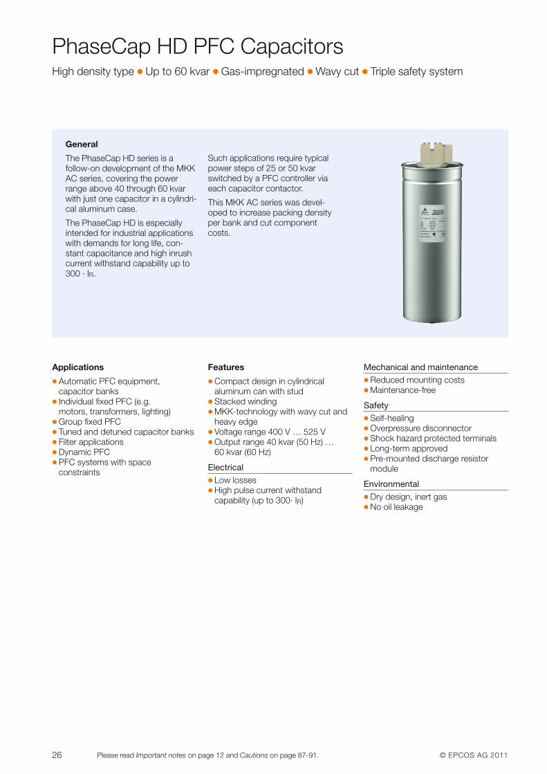
General
The PhaseCap HD series is afollow-on development of the MKKAC series, covering the powerrange above 40 through 60 kvarwith just one capacitor in a cylindri-cal aluminum case.
The PhaseCap HD is especially intended for industrial applicationswith demands for long life, con-stant capacitance and high inrushcurrent withstand capability up to300 · IR.
Such applications require typicalpower steps of 25 or 50 kvarswitched by a PFC controller viaeach capacitor contactor.
This MKK AC series was devel-oped to increase packing densityper bank and cut componentcosts.
Applications
� Automatic PFC equipment, capacitor banks
� Individual fixed PFC (e.g. motors, transformers, lighting)
� Group fixed PFC� Tuned and detuned capacitor banks� Filter applications� Dynamic PFC� PFC systems with space
constraints
Features
� Compact design in cylindrical aluminum can with stud
� Stacked winding � MKK-technology with wavy cut and
heavy edge� Voltage range 400 V … 525 V� Output range 40 kvar (50 Hz) …
60 kvar (60 Hz)
Electrical� Low losses� High pulse current withstand
capability (up to 300· IR)
Mechanical and maintenance� Reduced mounting costs� Maintenance-free
Safety� Self-healing� Overpressure disconnector� Shock hazard protected terminals � Long-term approved� Pre-mounted discharge resistor
module
Environmental� Dry design, inert gas� No oil leakage
© EPCOS AG 2011 27Please read Important notes on page 12 and Cautions on page 87-91.
PhaseCap HD PFC CapacitorsHigh density type � Up to 60 kvar � Gas-impregnated � Wavy cut � Triple safety system
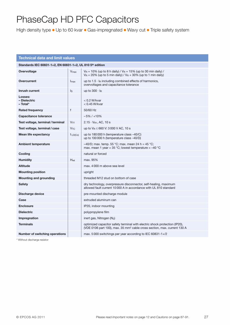
Technical data and limit values
Standards IEC 60831-1+2, EN 60831-1+2, UL 810 5th edition
Overvoltage Vmax VR + 10% (up to 8 h daily) / VR + 15% (up to 30 min daily) /VR + 20% (up to 5 min daily) / VR + 30% (up to 1 min daily)
Overcurrent Imax up to 1.5 · IR including combined effects of harmonics, overvoltages and capacitance tolerance
Inrush current IS up to 300 · IR
Losses:– Dielectric < 0.2 W/kvar– Total* < 0.45 W/kvar
Rated frequency f 50/60 Hz
Capacitance tolerance – 5% / +10%
Test voltage, terminal / terminal VTT 2.15 · VR1, AC, 10 s
Test voltage, terminal / case VTC up to VR ≤ 660 V: 3 000 V AC, 10 s
Mean life expectancy t LD(Co) up to 180 000 h (temperature class –40/C) up to 130 000 h (temperature class –40/D)
Ambient temperature –40/D; max. temp. 55 °C; max. mean 24 h = 45 °C; max. mean 1 year = 35 °C; lowest temperature = –40 °C
Cooling natural or forced
Humidity Hrel max. 95%
Altitude max. 4 000 m above sea level
Mounting position upright
Mounting and grounding threaded M12 stud on bottom of case
Safety dry technology, overpressure disconnector, self-healing, maximum allowed fault current 10 000 A in accordance with UL 810 standard
Discharge device pre-mounted discharge module
Case extruded aluminum can
Enclosure IP20, indoor mounting
Dielectric polypropylene film
Impregnation inert gas, Nitrogen (N2)
Terminals optimized capacitor safety terminal with electric shock protection (IP20),(VDE 0106 part 100), max. 35 mm2 cable cross section, max. current 130 A
Number of switching operations max. 5 000 switchings per year according to IEC 60831-1+/2
* Without discharge resistor
28 © EPCOS AG 2011Please read Important notes on page 12 and Cautions on page 87-91.
PhaseCap HD PFC CapacitorsHigh density type � Up to 60 kvar � Gas-impregnated � Wavy cut � Triple safety system
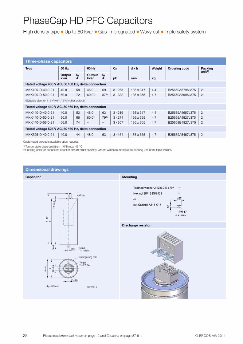
Three-phase capacitors
Customized products available upon request. 1) Temperature class deviation –40/B max. 45 °C2) Packing units for capacitors equal minimum order quantity. Orders will be rounded up to packing unit or multiple thereof.
Type 50 Hz 60 Hz CR d x h Weight Ordering code Packingunit2)
Output IR Output IRkvar A kvar A µF mm kg
Rated voltage 400 V AC, 50 / 60 Hz, delta connection
MKK400-D-40.0-21 40.0 58 48.0 69 3 · 265 136 x 317 4.4 B25669A3796J375 2
MKK400-D-50.0-21 50.0 72 60.01) 871) 3 · 332 136 x 355 4.7 B25669A3996J375 2
(Suitable also for 415 V with 7.6% higher output)
Rated voltage 440 V AC, 50 / 60 Hz, delta connection
MKK440-D-40.0-21 40.0 52 48.0 63 3 · 219 136 x 317 4.4 B25669A4657J375 2
MKK440-D-50.0-21 50.0 66 60.01) 791) 3 · 274 136 x 355 4.7 B25669A4827J375 2
MKK440-D-56.0-21 56.0 74 – – 3 · 307 136 x 355 4.7 B25669B4927J375 2
Rated voltage 525 V AC, 50 / 60 Hz, delta connection
MKK525-D-40.0-21 40.0 44 48.0 53 3 · 154 136 x 355 4.7 B25669A5467J375 2
Dimensional drawings
Capacitor Mounting
Discharge resistor
KLK1394-V
Hex nut BM12 DIN 439
or
nut C61010-A415-C15
Toothed washer J 12.5 DIN 6797
18
SW 17
ø22
4.5±
0.5
h+50
5.5 mm
© EPCOS AG 2011 29Please read Important notes on page 12 and Cautions on page 87-91.
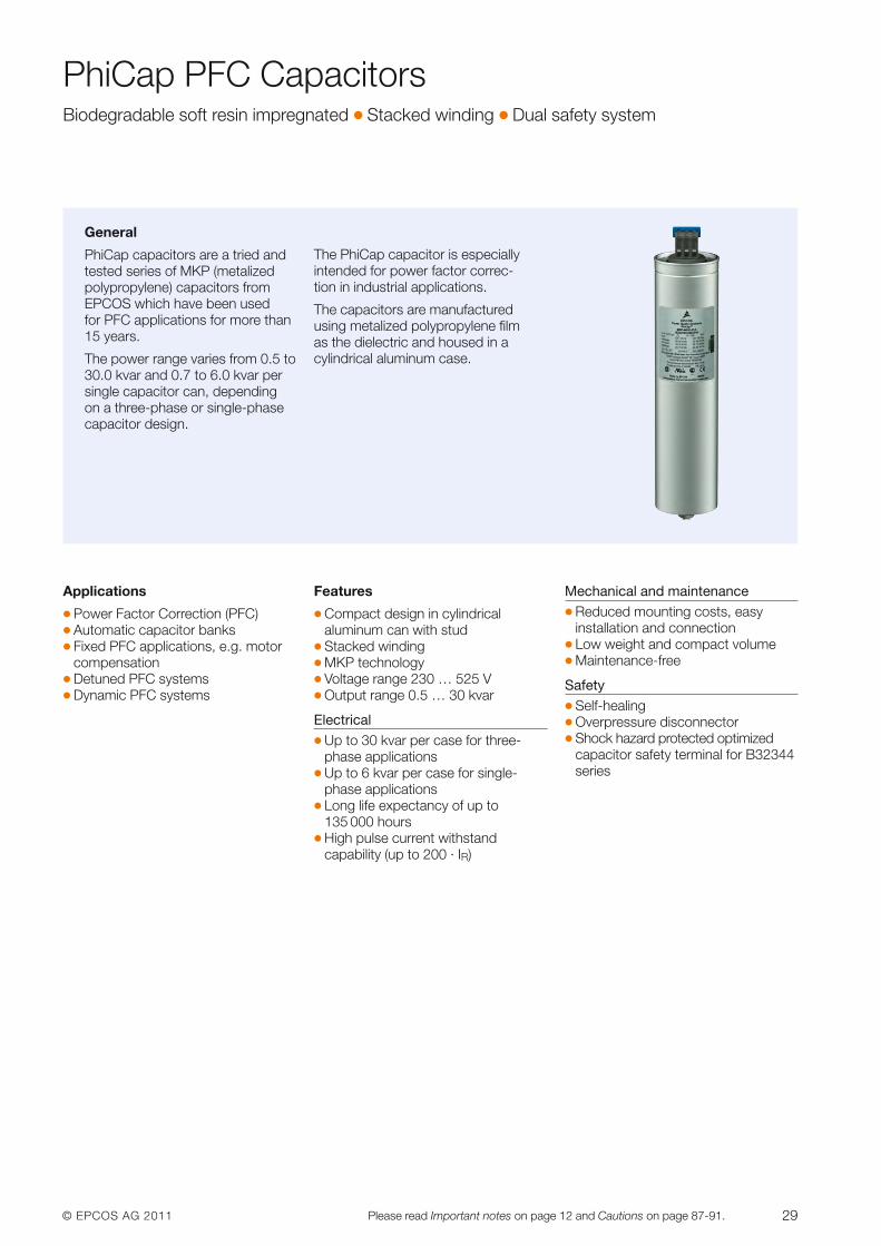
PhiCap PFC CapacitorsBiodegradable soft resin impregnated � Stacked winding � Dual safety system
Applications
� Power Factor Correction (PFC)� Automatic capacitor banks� Fixed PFC applications, e.g. motor
compensation� Detuned PFC systems� Dynamic PFC systems
Features
� Compact design in cylindrical aluminum can with stud
� Stacked winding� MKP technology� Voltage range 230 … 525 V� Output range 0.5 … 30 kvar
Electrical� Up to 30 kvar per case for three-
phase applications� Up to 6 kvar per case for single-
phase applications� Long life expectancy of up to
135 000 hours� High pulse current withstand
capability (up to 200 · IR)
Mechanical and maintenance� Reduced mounting costs, easy
installation and connection� Low weight and compact volume� Maintenance-free
Safety� Self-healing� Overpressure disconnector� Shock hazard protected optimized
capacitor safety terminal for B32344series
General
PhiCap capacitors are a tried andtested series of MKP (metalizedpolypropylene) capacitors from EPCOS which have been used for PFC applications for more than15 years.
The power range varies from 0.5 to30.0 kvar and 0.7 to 6.0 kvar persingle capacitor can, depending on a three-phase or single-phasecapacitor design.
The PhiCap capacitor is especiallyintended for power factor correc-tion in industrial applications.
The capacitors are manufacturedusing metalized polypropylene filmas the dielectric and housed in acylindrical aluminum case.
30 © EPCOS AG 2011Please read Important notes on page 12 and Cautions on page 87-91.
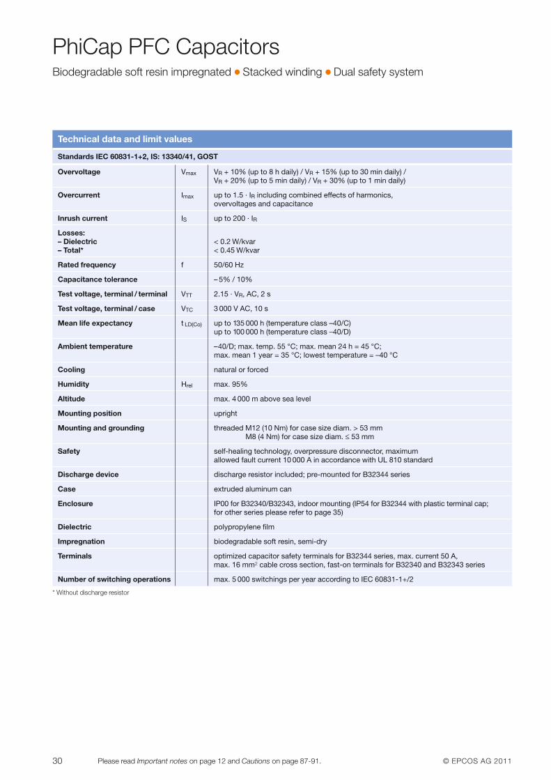
PhiCap PFC CapacitorsBiodegradable soft resin impregnated � Stacked winding � Dual safety system
Technical data and limit values
* Without discharge resistor
Standards IEC 60831-1+2, IS: 13340/41, GOST
Overvoltage Vmax VR + 10% (up to 8 h daily) / VR + 15% (up to 30 min daily) /VR + 20% (up to 5 min daily) / VR + 30% (up to 1 min daily)
Overcurrent Imax up to 1.5 · IR including combined effects of harmonics, overvoltages and capacitance
Inrush current IS up to 200 · IR
Losses:– Dielectric < 0.2 W/kvar– Total* < 0.45 W/kvar
Rated frequency f 50/60 Hz
Capacitance tolerance – 5% / 10%
Test voltage, terminal / terminal VTT 2.15 · VR, AC, 2 s
Test voltage, terminal / case VTC 3 000 V AC, 10 s
Mean life expectancy t LD(Co) up to 135 000 h (temperature class –40/C)up to 100 000 h (temperature class –40/D)
Ambient temperature –40/D; max. temp. 55 °C; max. mean 24 h = 45 °C; max. mean 1 year = 35 °C; lowest temperature = –40 °C
Cooling natural or forced
Humidity Hrel max. 95%
Altitude max. 4 000 m above sea level
Mounting position upright
Mounting and grounding threaded M12 (10 Nm) for case size diam. > 53 mmM8 (4 Nm) for case size diam. ≤ 53 mm
Safety self-healing technology, overpressure disconnector, maximum allowed fault current 10 000 A in accordance with UL 810 standard
Discharge device discharge resistor included; pre-mounted for B32344 series
Case extruded aluminum can
Enclosure IP00 for B32340/B32343, indoor mounting (IP54 for B32344 with plastic terminal cap;for other series please refer to page 35)
Dielectric polypropylene film
Impregnation biodegradable soft resin, semi-dry
Terminals optimized capacitor safety terminals for B32344 series, max. current 50 A,max. 16 mm2 cable cross section, fast-on terminals for B32340 and B32343 series
Number of switching operations max. 5 000 switchings per year according to IEC 60831-1+/2
© EPCOS AG 2011 31Please read Important notes on page 12 and Cautions on page 87-91.
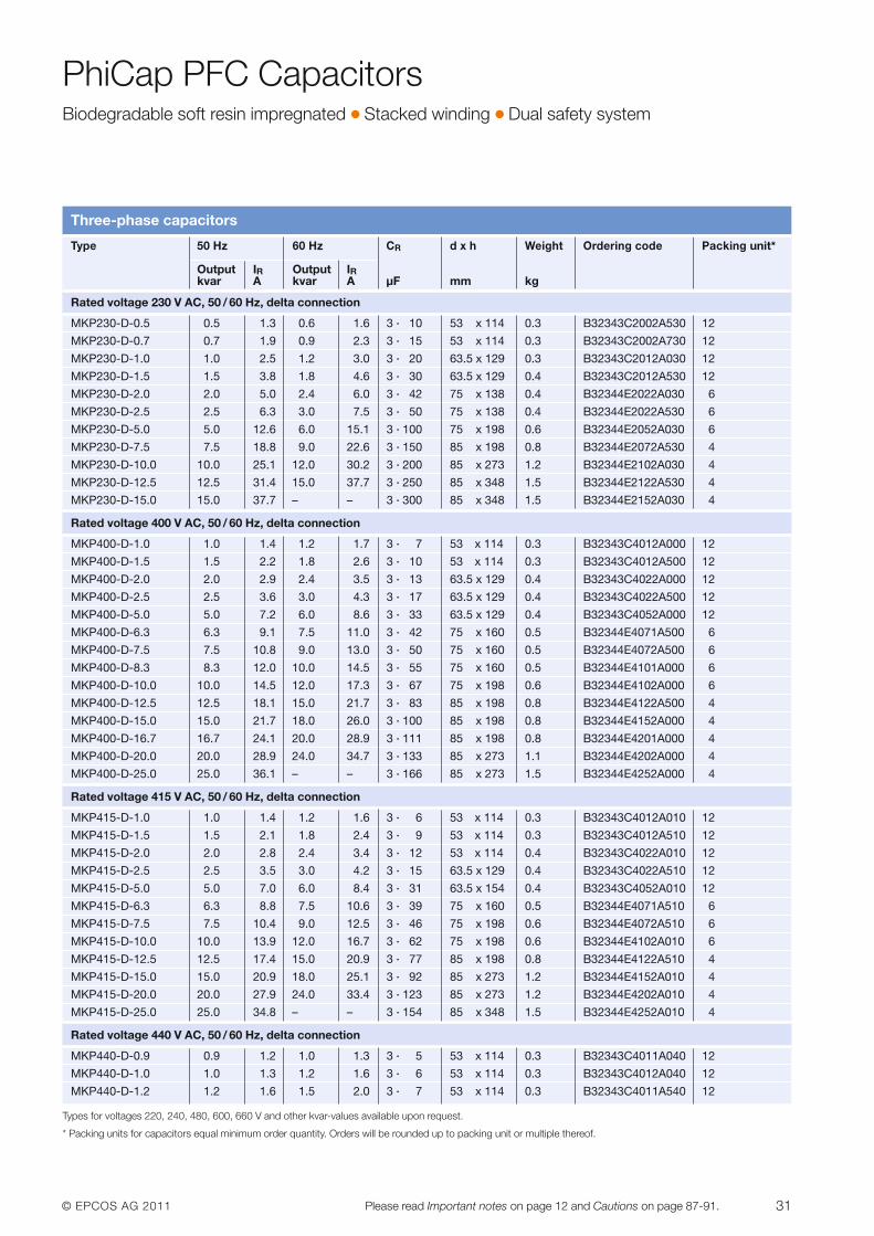
PhiCap PFC CapacitorsBiodegradable soft resin impregnated � Stacked winding � Dual safety system
Three-phase capacitors
Types for voltages 220, 240, 480, 600, 660 V and other kvar-values available upon request.
* Packing units for capacitors equal minimum order quantity. Orders will be rounded up to packing unit or multiple thereof.
Type 50 Hz 60 Hz CR d x h Weight Ordering code Packing unit*
Output IR Output IRkvar A kvar A µF mm kg
Rated voltage 230 V AC, 50 / 60 Hz, delta connection
MKP230-D-0.5 0.5 1.3 0.6 1.6 3 · 10 53 x 114 0.3 B32343C2002A530 12
MKP230-D-0.7 0.7 1.9 0.9 2.3 3 · 15 53 x 114 0.3 B32343C2002A730 12
MKP230-D-1.0 1.0 2.5 1.2 3.0 3 · 20 63.5 x 129 0.3 B32343C2012A030 12
MKP230-D-1.5 1.5 3.8 1.8 4.6 3 · 30 63.5 x 129 0.4 B32343C2012A530 12
MKP230-D-2.0 2.0 5.0 2.4 6.0 3 · 42 75 x 138 0.4 B32344E2022A030 6
MKP230-D-2.5 2.5 6.3 3.0 7.5 3 · 50 75 x 138 0.4 B32344E2022A530 6
MKP230-D-5.0 5.0 12.6 6.0 15.1 3 · 100 75 x 198 0.6 B32344E2052A030 6
MKP230-D-7.5 7.5 18.8 9.0 22.6 3 · 150 85 x 198 0.8 B32344E2072A530 4
MKP230-D-10.0 10.0 25.1 12.0 30.2 3 · 200 85 x 273 1.2 B32344E2102A030 4
MKP230-D-12.5 12.5 31.4 15.0 37.7 3 · 250 85 x 348 1.5 B32344E2122A530 4
MKP230-D-15.0 15.0 37.7 – – 3 · 300 85 x 348 1.5 B32344E2152A030 4
Rated voltage 400 V AC, 50 / 60 Hz, delta connection
MKP400-D-1.0 1.0 1.4 1.2 1.7 3 · 7 53 x 114 0.3 B32343C4012A000 12
MKP400-D-1.5 1.5 2.2 1.8 2.6 3 · 10 53 x 114 0.3 B32343C4012A500 12
MKP400-D-2.0 2.0 2.9 2.4 3.5 3 · 13 63.5 x 129 0.4 B32343C4022A000 12
MKP400-D-2.5 2.5 3.6 3.0 4.3 3 · 17 63.5 x 129 0.4 B32343C4022A500 12
MKP400-D-5.0 5.0 7.2 6.0 8.6 3 · 33 63.5 x 129 0.4 B32343C4052A000 12
MKP400-D-6.3 6.3 9.1 7.5 11.0 3 · 42 75 x 160 0.5 B32344E4071A500 6
MKP400-D-7.5 7.5 10.8 9.0 13.0 3 · 50 75 x 160 0.5 B32344E4072A500 6
MKP400-D-8.3 8.3 12.0 10.0 14.5 3 · 55 75 x 160 0.5 B32344E4101A000 6
MKP400-D-10.0 10.0 14.5 12.0 17.3 3 · 67 75 x 198 0.6 B32344E4102A000 6
MKP400-D-12.5 12.5 18.1 15.0 21.7 3 · 83 85 x 198 0.8 B32344E4122A500 4
MKP400-D-15.0 15.0 21.7 18.0 26.0 3 · 100 85 x 198 0.8 B32344E4152A000 4
MKP400-D-16.7 16.7 24.1 20.0 28.9 3 · 111 85 x 198 0.8 B32344E4201A000 4
MKP400-D-20.0 20.0 28.9 24.0 34.7 3 · 133 85 x 273 1.1 B32344E4202A000 4
MKP400-D-25.0 25.0 36.1 – – 3 · 166 85 x 273 1.5 B32344E4252A000 4
Rated voltage 415 V AC, 50 / 60 Hz, delta connection
MKP415-D-1.0 1.0 1.4 1.2 1.6 3 · 6 53 x 114 0.3 B32343C4012A010 12
MKP415-D-1.5 1.5 2.1 1.8 2.4 3 · 9 53 x 114 0.3 B32343C4012A510 12
MKP415-D-2.0 2.0 2.8 2.4 3.4 3 · 12 53 x 114 0.4 B32343C4022A010 12
MKP415-D-2.5 2.5 3.5 3.0 4.2 3 · 15 63.5 x 129 0.4 B32343C4022A510 12
MKP415-D-5.0 5.0 7.0 6.0 8.4 3 · 31 63.5 x 154 0.4 B32343C4052A010 12
MKP415-D-6.3 6.3 8.8 7.5 10.6 3 · 39 75 x 160 0.5 B32344E4071A510 6
MKP415-D-7.5 7.5 10.4 9.0 12.5 3 · 46 75 x 198 0.6 B32344E4072A510 6
MKP415-D-10.0 10.0 13.9 12.0 16.7 3 · 62 75 x 198 0.6 B32344E4102A010 6
MKP415-D-12.5 12.5 17.4 15.0 20.9 3 · 77 85 x 198 0.8 B32344E4122A510 4
MKP415-D-15.0 15.0 20.9 18.0 25.1 3 · 92 85 x 273 1.2 B32344E4152A010 4
MKP415-D-20.0 20.0 27.9 24.0 33.4 3 · 123 85 x 273 1.2 B32344E4202A010 4
MKP415-D-25.0 25.0 34.8 – – 3 · 154 85 x 348 1.5 B32344E4252A010 4
Rated voltage 440 V AC, 50 / 60 Hz, delta connection
MKP440-D-0.9 0.9 1.2 1.0 1.3 3 · 5 53 x 114 0.3 B32343C4011A040 12
MKP440-D-1.0 1.0 1.3 1.2 1.6 3 · 6 53 x 114 0.3 B32343C4012A040 12
MKP440-D-1.2 1.2 1.6 1.5 2.0 3 · 7 53 x 114 0.3 B32343C4011A540 12
32 © EPCOS AG 2011Please read Important notes on page 12 and Cautions on page 87-91.
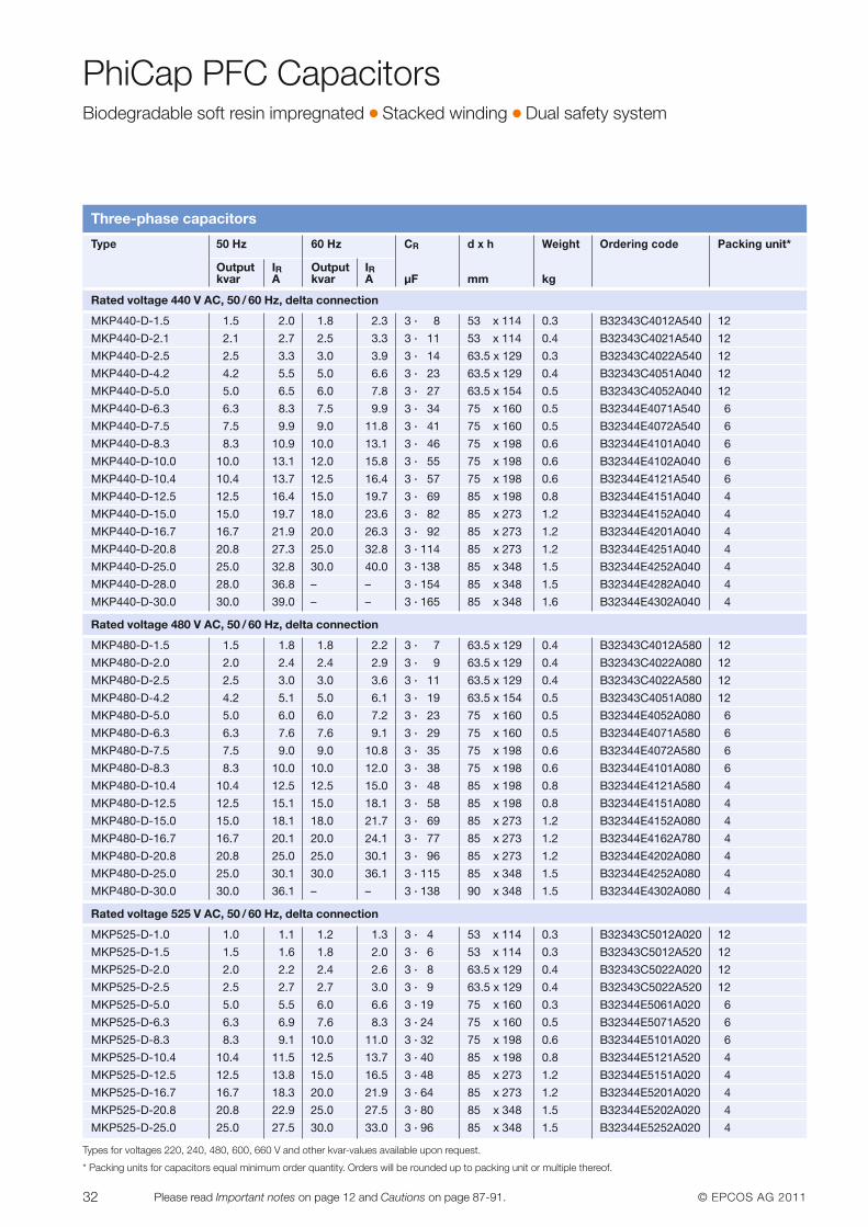
PhiCap PFC CapacitorsBiodegradable soft resin impregnated � Stacked winding � Dual safety system
Three-phase capacitors
Types for voltages 220, 240, 480, 600, 660 V and other kvar-values available upon request.
* Packing units for capacitors equal minimum order quantity. Orders will be rounded up to packing unit or multiple thereof.
Type 50 Hz 60 Hz CR d x h Weight Ordering code Packing unit*
Output IR Output IRkvar A kvar A µF mm kg
Rated voltage 440 V AC, 50 / 60 Hz, delta connection
MKP440-D-1.5 1.5 2.0 1.8 2.3 3 · 8 53 x 114 0.3 B32343C4012A540 12
MKP440-D-2.1 2.1 2.7 2.5 3.3 3 · 11 53 x 114 0.4 B32343C4021A540 12
MKP440-D-2.5 2.5 3.3 3.0 3.9 3 · 14 63.5 x 129 0.3 B32343C4022A540 12
MKP440-D-4.2 4.2 5.5 5.0 6.6 3 · 23 63.5 x 129 0.4 B32343C4051A040 12
MKP440-D-5.0 5.0 6.5 6.0 7.8 3 · 27 63.5 x 154 0.5 B32343C4052A040 12
MKP440-D-6.3 6.3 8.3 7.5 9.9 3 · 34 75 x 160 0.5 B32344E4071A540 6
MKP440-D-7.5 7.5 9.9 9.0 11.8 3 · 41 75 x 160 0.5 B32344E4072A540 6
MKP440-D-8.3 8.3 10.9 10.0 13.1 3 · 46 75 x 198 0.6 B32344E4101A040 6
MKP440-D-10.0 10.0 13.1 12.0 15.8 3 · 55 75 x 198 0.6 B32344E4102A040 6
MKP440-D-10.4 10.4 13.7 12.5 16.4 3 · 57 75 x 198 0.6 B32344E4121A540 6
MKP440-D-12.5 12.5 16.4 15.0 19.7 3 · 69 85 x 198 0.8 B32344E4151A040 4
MKP440-D-15.0 15.0 19.7 18.0 23.6 3 · 82 85 x 273 1.2 B32344E4152A040 4
MKP440-D-16.7 16.7 21.9 20.0 26.3 3 · 92 85 x 273 1.2 B32344E4201A040 4
MKP440-D-20.8 20.8 27.3 25.0 32.8 3 · 114 85 x 273 1.2 B32344E4251A040 4
MKP440-D-25.0 25.0 32.8 30.0 40.0 3 · 138 85 x 348 1.5 B32344E4252A040 4
MKP440-D-28.0 28.0 36.8 – – 3 · 154 85 x 348 1.5 B32344E4282A040 4
MKP440-D-30.0 30.0 39.0 – – 3 · 165 85 x 348 1.6 B32344E4302A040 4
Rated voltage 480 V AC, 50 / 60 Hz, delta connection
MKP480-D-1.5 1.5 1.8 1.8 2.2 3 · 7 63.5 x 129 0.4 B32343C4012A580 12
MKP480-D-2.0 2.0 2.4 2.4 2.9 3 · 9 63.5 x 129 0.4 B32343C4022A080 12
MKP480-D-2.5 2.5 3.0 3.0 3.6 3 · 11 63.5 x 129 0.4 B32343C4022A580 12
MKP480-D-4.2 4.2 5.1 5.0 6.1 3 · 19 63.5 x 154 0.5 B32343C4051A080 12
MKP480-D-5.0 5.0 6.0 6.0 7.2 3 · 23 75 x 160 0.5 B32344E4052A080 6
MKP480-D-6.3 6.3 7.6 7.6 9.1 3 · 29 75 x 160 0.5 B32344E4071A580 6
MKP480-D-7.5 7.5 9.0 9.0 10.8 3 · 35 75 x 198 0.6 B32344E4072A580 6
MKP480-D-8.3 8.3 10.0 10.0 12.0 3 · 38 75 x 198 0.6 B32344E4101A080 6
MKP480-D-10.4 10.4 12.5 12.5 15.0 3 · 48 85 x 198 0.8 B32344E4121A580 4
MKP480-D-12.5 12.5 15.1 15.0 18.1 3 · 58 85 x 198 0.8 B32344E4151A080 4
MKP480-D-15.0 15.0 18.1 18.0 21.7 3 · 69 85 x 273 1.2 B32344E4152A080 4
MKP480-D-16.7 16.7 20.1 20.0 24.1 3 · 77 85 x 273 1.2 B32344E4162A780 4
MKP480-D-20.8 20.8 25.0 25.0 30.1 3 · 96 85 x 273 1.2 B32344E4202A080 4
MKP480-D-25.0 25.0 30.1 30.0 36.1 3 · 115 85 x 348 1.5 B32344E4252A080 4
MKP480-D-30.0 30.0 36.1 – – 3 · 138 90 x 348 1.5 B32344E4302A080 4
Rated voltage 525 V AC, 50 / 60 Hz, delta connection
MKP525-D-1.0 1.0 1.1 1.2 1.3 3 · 4 53 x 114 0.3 B32343C5012A020 12
MKP525-D-1.5 1.5 1.6 1.8 2.0 3 · 6 53 x 114 0.3 B32343C5012A520 12
MKP525-D-2.0 2.0 2.2 2.4 2.6 3 · 8 63.5 x 129 0.4 B32343C5022A020 12
MKP525-D-2.5 2.5 2.7 2.7 3.0 3 · 9 63.5 x 129 0.4 B32343C5022A520 12
MKP525-D-5.0 5.0 5.5 6.0 6.6 3 · 19 75 x 160 0.3 B32344E5061A020 6
MKP525-D-6.3 6.3 6.9 7.6 8.3 3 · 24 75 x 160 0.5 B32344E5071A520 6
MKP525-D-8.3 8.3 9.1 10.0 11.0 3 · 32 75 x 198 0.6 B32344E5101A020 6
MKP525-D-10.4 10.4 11.5 12.5 13.7 3 · 40 85 x 198 0.8 B32344E5121A520 4
MKP525-D-12.5 12.5 13.8 15.0 16.5 3 · 48 85 x 273 1.2 B32344E5151A020 4
MKP525-D-16.7 16.7 18.3 20.0 21.9 3 · 64 85 x 273 1.2 B32344E5201A020 4
MKP525-D-20.8 20.8 22.9 25.0 27.5 3 · 80 85 x 348 1.5 B32344E5202A020 4
MKP525-D-25.0 25.0 27.5 30.0 33.0 3 · 96 85 x 348 1.5 B32344E5252A020 4
© EPCOS AG 2011 33Please read Important notes on page 12 and Cautions on page 87-91.
PhiCap PFC CapacitorsBiodegradable soft resin impregnated � Stacked winding � Dual safety system
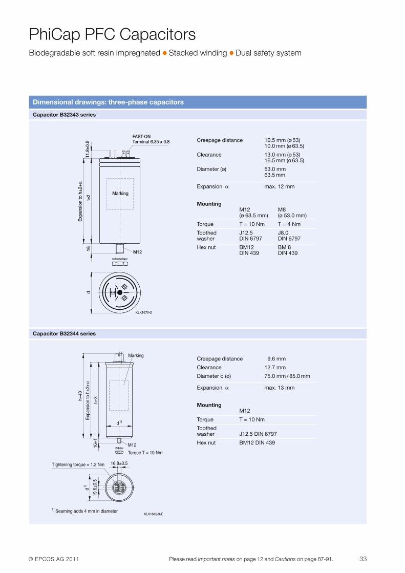
Dimensional drawings: three-phase capacitors
Capacitor B32343 series
Capacitor B32344 series
KLK1670-2
11.8
±0.5
h±2
16 M12
d
Marking
Expa
nsio
n to
h±2
+α
FAST-ONTerminal 6.35 x 0.8 Creepage distance 10.5 mm (ø 53)
10.0 mm (ø 63.5)
Clearance 13.0 mm (ø 53) 16.5 mm (ø 63.5)
Diameter (ø) 53.0 mm63.5 mm
Expansion α max. 12 mm
MountingM12 M8(ø 63.5 mm) (ø 53.0 mm)
Torque T = 10 Nm T = 4 Nm
Toothed J12.5 J8.0 washer DIN 6797 DIN 6797
Hex nut BM12 BM 8 DIN 439 DIN 439
Creepage distance 9.6 mm
Clearance 12.7 mm
Diameter d (ø) 75.0 mm / 85.0 mm
Expansion α max. 13 mm
MountingM12
Torque T = 10 Nm
Toothed washer J12.5 DIN 6797
Hex nut BM12 DIN 439
34 © EPCOS AG 2011Please read Important notes on page 12 and Cautions on page 87-91.
PhiCap PFC CapacitorsBiodegradable soft resin impregnated � Stacked winding � Dual safety system
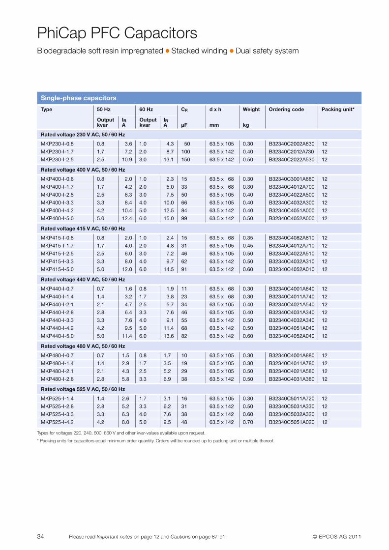
Single-phase capacitors
Types for voltages 220, 240, 600, 660 V and other kvar-values available upon request.
* Packing units for capacitors equal minimum order quantity. Orders will be rounded up to packing unit or multiple thereof.
Type 50 Hz 60 Hz CR d x h Weight Ordering code Packing unit*
Output IR Output IRkvar A kvar A µF mm kg
Rated voltage 230 V AC, 50 / 60 Hz
MKP230-I-0.8 0.8 3.6 1.0 4.3 50 63.5 x 10⁵ 0.30 B32340C2002A830 12
MKP230-I-1.7 1.7 7.2 2.0 8.7 100 63.5 x 142 0.40 B32340C2012A730 12
MKP230-I-2.5 2.5 10.9 3.0 13.1 150 63.5 x 142 0.50 B32340C2022A530 12
Rated voltage 400 V AC, 50 / 60 Hz
MKP400-I-0.8 0.8 2.0 1.0 2.3 15 63.5 x 68 0.30 B32340C3001A880 12
MKP400-I-1.7 1.7 4.2 2.0 5.0 33 63.5 x 68 0.30 B32340C4012A700 12
MKP400-I-2.5 2.5 6.3 3.0 7.5 50 63.5 x 10⁵ 0.40 B32340C4022A500 12
MKP400-I-3.3 3.3 8.4 4.0 10.0 66 63.5 x 10⁵ 0.40 B32340C4032A300 12
MKP400-I-4.2 4.2 10.4 5.0 12.5 84 63.5 x 142 0.40 B32340C4051A000 12
MKP400-I-5.0 5.0 12.4 6.0 15.0 99 63.5 x 142 0.50 B32340C4052A000 12
Rated voltage 415 V AC, 50 / 60 Hz
MKP415-I-0.8 0.8 2.0 1.0 2.4 15 63.5 x 68 0.35 B32340C4082A810 12
MKP415-I-1.7 1.7 4.0 2.0 4.8 31 63.5 x 10⁵ 0.45 B32340C4012A710 12
MKP415-I-2.5 2.5 6.0 3.0 7.2 46 63.5 x 10⁵ 0.50 B32340C4022A510 12
MKP415-I-3.3 3.3 8.0 4.0 9.7 62 63.5 x 142 0.50 B32340C4032A310 12
MKP415-I-5.0 5.0 12.0 6.0 14.5 91 63.5 x 142 0.60 B32340C4052A010 12
Rated voltage 440 V AC, 50 / 60 Hz
MKP440-I-0.7 0.7 1.6 0.8 1.9 11 63.5 x 68 0.30 B32340C4001A840 12
MKP440-I-1.4 1.4 3.2 1.7 3.8 23 63.5 x 68 0.30 B32340C4011A740 12
MKP440-I-2.1 2.1 4.7 2.5 5.7 34 63.5 x 10⁵ 0.40 B32340C4021A540 12
MKP440-I-2.8 2.8 6.4 3.3 7.6 46 63.5 x 10⁵ 0.40 B32340C4031A340 12
MKP440-I-3.3 3.3 7.6 4.0 9.1 55 63.5 x 142 0.50 B32340C4032A340 12
MKP440-I-4.2 4.2 9.5 5.0 11.4 68 63.5 x 142 0.50 B32340C4051A040 12
MKP440-I-5.0 5.0 11.4 6.0 13.6 82 63.5 x 142 0.60 B32340C4052A040 12
Rated voltage 480 V AC, 50 / 60 Hz
MKP480-I-0.7 0.7 1.5 0.8 1.7 10 63.5 x 10⁵ 0.30 B32340C4001A880 12
MKP480-I-1.4 1.4 2.9 1.7 3.5 19 63.5 x 10⁵ 0.30 B32340C4011A780 12
MKP480-I-2.1 2.1 4.3 2.5 5.2 29 63.5 x 10⁵ 0.50 B32340C4021A580 12
MKP480-I-2.8 2.8 5.8 3.3 6.9 38 63.5 x 142 0.50 B32340C4031A380 12
Rated voltage 525 V AC, 50 / 60 Hz
MKP525-I-1.4 1.4 2.6 1.7 3.1 16 63.5 x 10⁵ 0.30 B32340C5011A720 12
MKP525-I-2.8 2.8 5.2 3.3 6.2 31 63.5 x 142 0.50 B32340C5031A330 12
MKP525-I-3.3 3.3 6.3 4.0 7.6 38 63.5 x 142 0.60 B32340C5032A320 12
MKP525-I-4.2 4.2 8.0 5.0 9.5 48 63.5 x 142 0.70 B32340C5051A020 12
© EPCOS AG 2011 35Please read Important notes on page 12 and Cautions on page 87-91.
PhiCap PFC CapacitorsBiodegradable soft resin impregnated � Stacked winding � Dual safety system
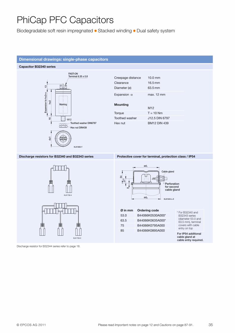
Dimensional drawings: single-phase capacitors
Capacitor B32340 series
Discharge resistors for B32340 and B32343 series Protective cover for terminal, protection class / IP54
KLK1669-Y
Terminal 6.35 x 0.8
13
h±2
16 M12
d±1
Marking
FAST-ON
Expa
nsio
n to
h±2
+α
Toothed washer DIN6797
Hex nut DIN439
Creepage distance 10.0 mm
Clearance 16.5 mm
Diameter (ø) 63.5 mm
Expansion α max. 12 mm
MountingM12
Torque T = 10 Nm
Toothed washer J12.5 DIN 6797
Hex nut BM12 DIN 439
KLK1645-L-E
ød1
ød2
821
1)54
Cable gland
Ø in mm Ordering code
53.0 B44066K0530A000*
63.5 B44066K0635A000*
75 B44066K0795A000
85 B44066K0895A000
1) Perforationfor second cable gland
* For B32340 andB32343 series (dia meter 53.0 and 63.5 mm), terminalcovers with cableentry on top
For IP54 additionalcable gland at cable entry required.
Discharge resistor for B32344 series refer to page 18.
36 © EPCOS AG 2011Please read Important notes on page 12 and Cautions on page 87-91.
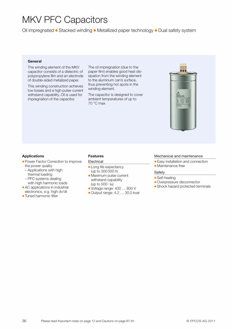
MKV PFC CapacitorsOil impregnated � Stacked winding � Metallized paper technology � Dual safety system
General
The winding element of the MKV capacitor consists of a dielectric ofpolypropylene film and an electrodeof double-sided metalized paper.
This winding construction achieveslow losses and a high pulse-currentwithstand capability. Oil is used forimpregnation of the capacitor.
The oil impregnation (due to the paper film) enables good heat dis-sipation from the winding element to the aluminum can’s surface, thus preventing hot spots in thewinding element.
The capacitor is designed to coverambient temperatures of up to70 °C max.
Applications� Power Factor Correction to improve
the power quality– Applications with high
thermal loading – PFC systems dealing
with high harmonic loads� AC applications in industrial
electronics, e.g. high dv/dt � Tuned harmonic filter
FeaturesElectrical� Long life expectancy
(up to 300 000 h)� Maximum pulse current
withstand capability (up to 500 · IR)
� Voltage range: 400 … 800 V� Output range: 4.2 … 30.0 kvar
Mechanical and maintenance� Easy installation and connection� Maintenance-free
Safety� Self-healing� Overpressure disconnector� Shock hazard protected terminals
© EPCOS AG 2011 37Please read Important notes on page 12 and Cautions on page 87-91.
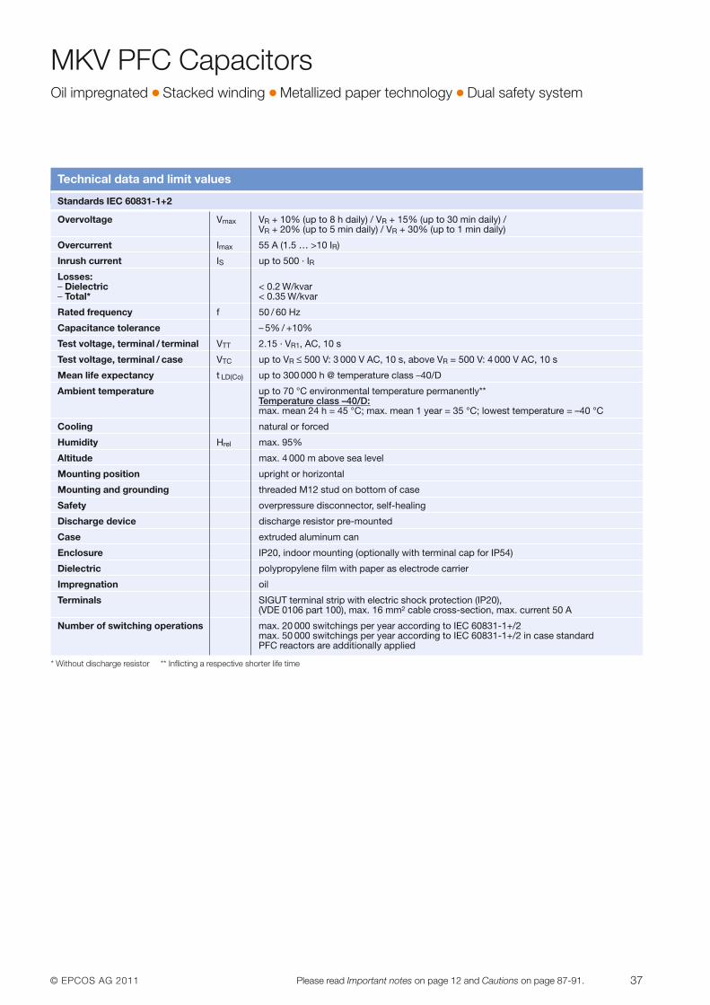
MKV PFC CapacitorsOil impregnated � Stacked winding � Metallized paper technology � Dual safety system
Technical data and limit values
Standards IEC 60831-1+2
Overvoltage Vmax VR + 10% (up to 8 h daily) / VR + 15% (up to 30 min daily) / VR + 20% (up to 5 min daily) / VR + 30% (up to 1 min daily)
Overcurrent Imax 55 A (1.5 … >10 IR)
Inrush current IS up to 500 · IR
Losses: – Dielectric < 0.2 W/kvar– Total* < 0.35 W/kvar
Rated frequency f 50 / 60 Hz
Capacitance tolerance – 5% / +10%
Test voltage, terminal / terminal VTT 2.15 · VR1, AC, 10 s
Test voltage, terminal / case VTC up to VR ≤ 500 V: 3 000 V AC, 10 s, above VR = 500 V: 4 000 V AC, 10 s
Mean life expectancy t LD(Co) up to 300 000 h @ temperature class –40/D
Ambient temperature up to 70 °C environmental temperature permanently** Temperature class –40/D:max. mean 24 h = 45 °C; max. mean 1 year = 35 °C; lowest temperature = –40 °C
Cooling natural or forced
Humidity Hrel max. 95%
Altitude max. 4 000 m above sea level
Mounting position upright or horizontal
Mounting and grounding threaded M12 stud on bottom of case
Safety overpressure disconnector, self-healing
Discharge device discharge resistor pre-mounted
Case extruded aluminum can
Enclosure IP20, indoor mounting (optionally with terminal cap for IP54)
Dielectric polypropylene film with paper as electrode carrier
Impregnation oil
Terminals SIGUT terminal strip with electric shock protection (IP20), (VDE 0106 part 100), max. 16 mm2 cable cross-section, max. current 50 A
Number of switching operations max. 20 000 switchings per year according to IEC 60831-1+/2max. 50 000 switchings per year according to IEC 60831-1+/2 in case standard PFC reactors are additionally applied
* Without discharge resistor ** Inflicting a respective shorter life time
38 © EPCOS AG 2011Please read Important notes on page 12 and Cautions on page 87-91.
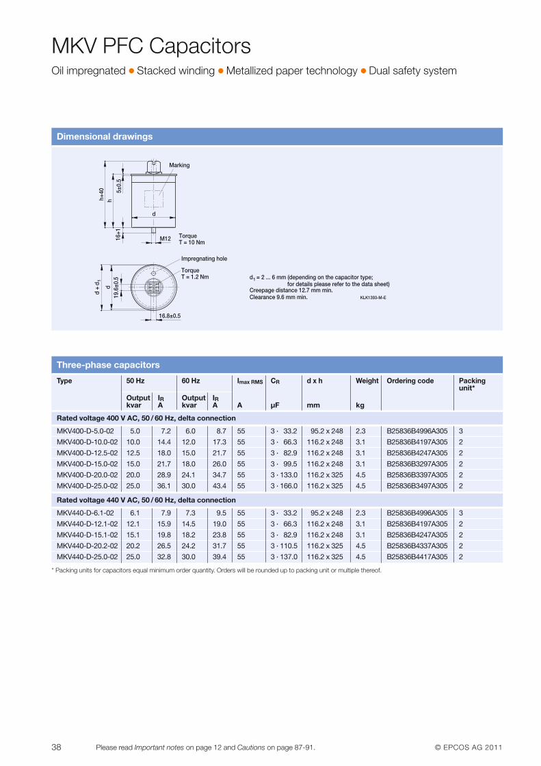
MKV PFC CapacitorsOil impregnated � Stacked winding � Metallized paper technology � Dual safety system
Dimensional drawings
KLK1393-M-E
5±0.
516
+1
M12
19.6
±0.5
16.8±0.5
Marking
TorqueT = 10 Nm
Impregnating hole
TorqueT = 1.2 Nm
Creepage distance 12.7 mm min.Clearance 9.6 mm min.
h+40
dh
d
d +
d1 = 2 ... 6 mm (depending on the capacitor type;
for details please refer to the data sheet)d1
Three-phase capacitors
Type 50 Hz 60 Hz Imax RMS CR d x h Weight Ordering code Packingunit*
Output IR Output IRkvar A kvar A A µF mm kg
Rated voltage 400 V AC, 50 / 60 Hz, delta connection
MKV400-D-5.0-02 5.0 7.2 6.0 8.7 55 3 · 33.2 95.2 x 248 2.3 B25836B4996A305 3
MKV400-D-10.0-02 10.0 14.4 12.0 17.3 55 3 · 66.3 116.2 x 248 3.1 B25836B4197A305 2
MKV400-D-12.5-02 12.5 18.0 15.0 21.7 55 3 · 82.9 116.2 x 248 3.1 B25836B4247A305 2
MKV400-D-15.0-02 15.0 21.7 18.0 26.0 55 3 · 99.5 116.2 x 248 3.1 B25836B3297A305 2
MKV400-D-20.0-02 20.0 28.9 24.1 34.7 55 3 · 133.0 116.2 x 325 4.5 B25836B3397A305 2
MKV400-D-25.0-02 25.0 36.1 30.0 43.4 55 3 · 166.0 116.2 x 325 4.5 B25836B3497A305 2
Rated voltage 440 V AC, 50 / 60 Hz, delta connection
MKV440-D-6.1-02 6.1 7.9 7.3 9.5 55 3 · 33.2 95.2 x 248 2.3 B25836B4996A305 3
MKV440-D-12.1-02 12.1 15.9 14.5 19.0 55 3 · 66.3 116.2 x 248 3.1 B25836B4197A305 2
MKV440-D-15.1-02 15.1 19.8 18.2 23.8 55 3 · 82.9 116.2 x 248 3.1 B25836B4247A305 2
MKV440-D-20.2-02 20.2 26.5 24.2 31.7 55 3 · 110.5 116.2 x 325 4.5 B25836B4337A305 2
MKV440-D-25.0-02 25.0 32.8 30.0 39.4 55 3 · 137.0 116.2 x 325 4.5 B25836B4417A305 2
* Packing units for capacitors equal minimum order quantity. Orders will be rounded up to packing unit or multiple thereof.
© EPCOS AG 2011 39Please read Important notes on page 12 and Cautions on page 87-91.
MKV PFC CapacitorsOil impregnated � Stacked winding � Metallized paper technology � Dual safety system
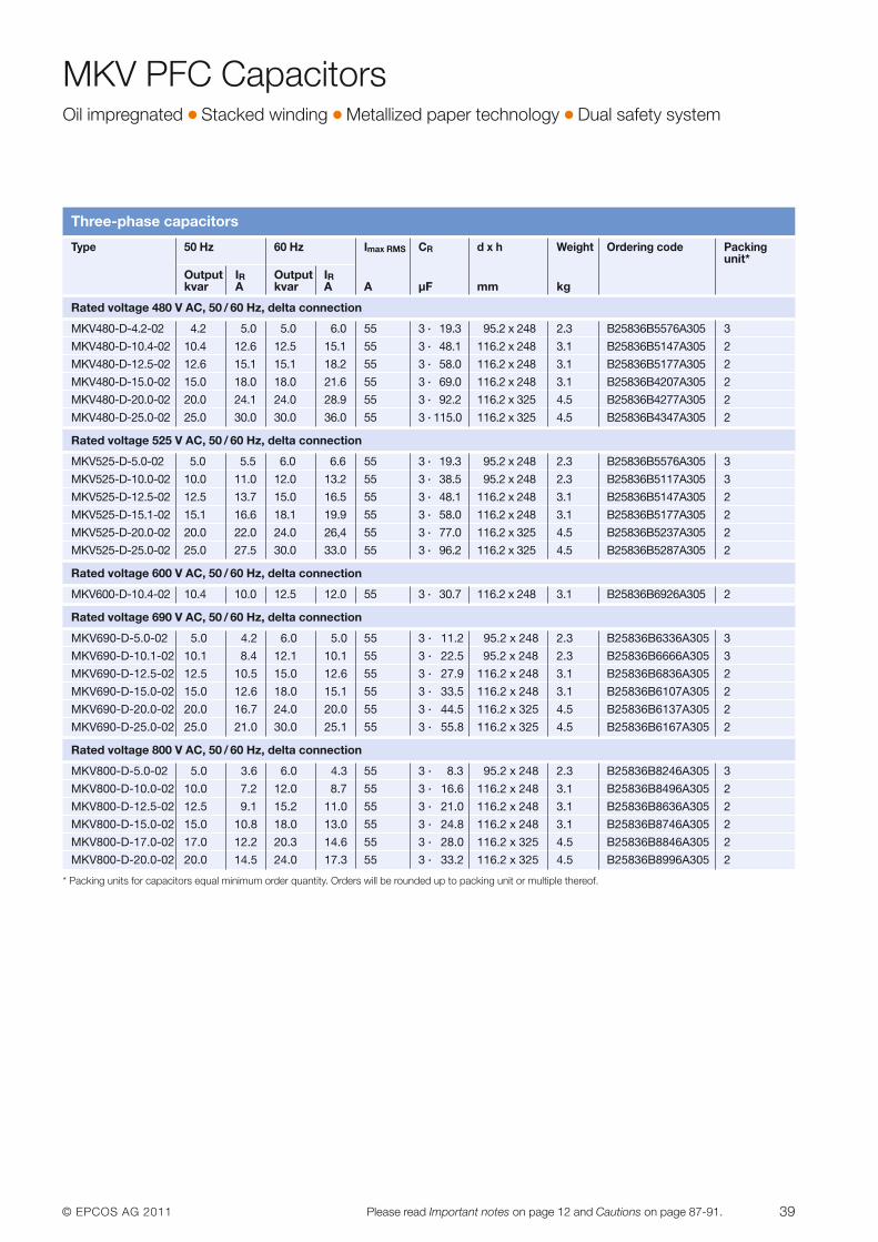
Three-phase capacitors
Type 50 Hz 60 Hz Imax RMS CR d x h Weight Ordering code Packingunit*
Output IR Output IRkvar A kvar A A µF mm kg
Rated voltage 480 V AC, 50 / 60 Hz, delta connection
MKV480-D-4.2-02 4.2 5.0 5.0 6.0 55 3 · 19.3 95.2 x 248 2.3 B25836B5576A305 3
MKV480-D-10.4-02 10.4 12.6 12.5 15.1 55 3 · 48.1 116.2 x 248 3.1 B25836B5147A305 2
MKV480-D-12.5-02 12.6 15.1 15.1 18.2 55 3 · 58.0 116.2 x 248 3.1 B25836B5177A305 2
MKV480-D-15.0-02 15.0 18.0 18.0 21.6 55 3 · 69.0 116.2 x 248 3.1 B25836B4207A305 2
MKV480-D-20.0-02 20.0 24.1 24.0 28.9 55 3 · 92.2 116.2 x 325 4.5 B25836B4277A305 2
MKV480-D-25.0-02 25.0 30.0 30.0 36.0 55 3 · 115.0 116.2 x 325 4.5 B25836B4347A305 2
Rated voltage 525 V AC, 50 / 60 Hz, delta connection
MKV525-D-5.0-02 5.0 5.5 6.0 6.6 55 3 · 19.3 95.2 x 248 2.3 B25836B5576A305 3
MKV525-D-10.0-02 10.0 11.0 12.0 13.2 55 3 · 38.5 95.2 x 248 2.3 B25836B5117A305 3
MKV525-D-12.5-02 12.5 13.7 15.0 16.5 55 3 · 48.1 116.2 x 248 3.1 B25836B5147A305 2
MKV525-D-15.1-02 15.1 16.6 18.1 19.9 55 3 · 58.0 116.2 x 248 3.1 B25836B5177A305 2
MKV525-D-20.0-02 20.0 22.0 24.0 26,4 55 3 · 77.0 116.2 x 325 4.5 B25836B5237A305 2
MKV525-D-25.0-02 25.0 27.5 30.0 33.0 55 3 · 96.2 116.2 x 325 4.5 B25836B5287A305 2
Rated voltage 600 V AC, 50 / 60 Hz, delta connection
MKV600-D-10.4-02 10.4 10.0 12.5 12.0 55 3 · 30.7 116.2 x 248 3.1 B25836B6926A305 2
Rated voltage 690 V AC, 50 / 60 Hz, delta connection
MKV690-D-5.0-02 5.0 4.2 6.0 5.0 55 3 · 11.2 95.2 x 248 2.3 B25836B6336A305 3
MKV690-D-10.1-02 10.1 8.4 12.1 10.1 55 3 · 22.5 95.2 x 248 2.3 B25836B6666A305 3
MKV690-D-12.5-02 12.5 10.5 15.0 12.6 55 3 · 27.9 116.2 x 248 3.1 B25836B6836A305 2
MKV690-D-15.0-02 15.0 12.6 18.0 15.1 55 3 · 33.5 116.2 x 248 3.1 B25836B6107A305 2
MKV690-D-20.0-02 20.0 16.7 24.0 20.0 55 3 · 44.5 116.2 x 325 4.5 B25836B6137A305 2
MKV690-D-25.0-02 25.0 21.0 30.0 25.1 55 3 · 55.8 116.2 x 325 4.5 B25836B6167A305 2
Rated voltage 800 V AC, 50 / 60 Hz, delta connection
MKV800-D-5.0-02 5.0 3.6 6.0 4.3 55 3 · 8.3 95.2 x 248 2.3 B25836B8246A305 3
MKV800-D-10.0-02 10.0 7.2 12.0 8.7 55 3 · 16.6 116.2 x 248 3.1 B25836B8496A305 2
MKV800-D-12.5-02 12.5 9.1 15.2 11.0 55 3 · 21.0 116.2 x 248 3.1 B25836B8636A305 2
MKV800-D-15.0-02 15.0 10.8 18.0 13.0 55 3 · 24.8 116.2 x 248 3.1 B25836B8746A305 2
MKV800-D-17.0-02 17.0 12.2 20.3 14.6 55 3 · 28.0 116.2 x 325 4.5 B25836B8846A305 2
MKV800-D-20.0-02 20.0 14.5 24.0 17.3 55 3 · 33.2 116.2 x 325 4.5 B25836B8996A305 2
* Packing units for capacitors equal minimum order quantity. Orders will be rounded up to packing unit or multiple thereof.
40 © EPCOS AG 2011Please read Important notes on page 12 and Cautions on page 87-91.
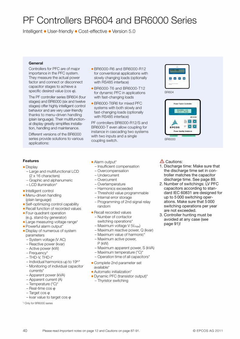
PF Controllers BR604 and BR6000 SeriesIntelligent � User-friendly � Cost-effective � Version 5.0
GeneralControllers for PFC are of major importance in the PFC system.They measure the actual powerfactor and connect or disconnectcapacitor stages to achieve a specific desired value (cos ϕ).
The PF controller series BR604 (fourstages) and BR6000 (six and twelvestages) offer highly intelligent controlbehavior and are very user-friendlythanks to menu-driven handling(plain language). Their multifunction-al display greatly simplifies installa-tion, handling and maintenance.
Different versions of the BR6000 series provide solutions to variousapplications:
� BR6000-R6 and BR6000-R12for conventional applications withslowly changing loads (optionallywith RS485 interface)
� BR6000-T6 and BR6000-T12for dynamic PFC in applicationswith fast-changing loads
� BR6000-T6R6 for mixed PFCsystems with both slowly andfast-changing loads (optionallywith RS485 interface)
PF controllers BR6000-R12/S andBR6000-T even allow coupling forinstance in cascading two systemswith two inputs and a single coupling switch.
BR604
BR6000
Features
� Display– Large and multifunctional LCD
(2 x 16 characters)– Graphic and alphanumeric – LCD illumination*
� Intelligent control� Menu-driven handling
(plain language)� Self-optimizing control capability � Recall function of recorded values� Four-quadrant operation
(e.g. stand-by generator)� Large measuring voltage range*� Powerful alarm output*� Display of numerous of system
parameters– System voltage (V AC)– Reactive power (kvar)– Active power (kW)– Frequency*– THD-V, THD-I*– Individual harmonics up to 19th*– Monitoring of individual capa ci tor
currents*– Apparent power (kVA)– Apparent current (A)– Temperature (°C)*– Real-time cos ϕ– Target cos ϕ– kvar value to target cos ϕ
� Alarm output*– Insufficient compensation– Overcompensation– Undercurrent– Overcurrent– Overtemperature– Harmonics exceeded– Threshold value programmable– Internal error storage– Programming of 2nd signal relay
random
� Recall recorded values– Number of contactor
switching operations*– Maximum voltage V (Vmax)– Maximum reactive power, Q (kvar)– Maximum value of harmonic*– Maximum active power,
P (kW)– Maximum apparent power, S (kVA)– Maximum temperature (°C)* – Operation time of all capacitors*
� Complete 2nd parameter set available*
� Automatic initialization*� Dynamic PFC (transistor output)*
– Thyristor switching
V Cautions:1. Discharge time: Make sure that
the discharge time set in con-troller matches the capacitordischarge time. See page 89.
2. Number of switchings: LV PFCcapacitors according to stan-dard IEC 60831 are designed forup to 5 000 switching op er -ations. Make sure that 5 000switching operations per yearare not exceeded.
3. Controller hunting must beavoided at any case (see page 91)!
*) Only for BR6000 series
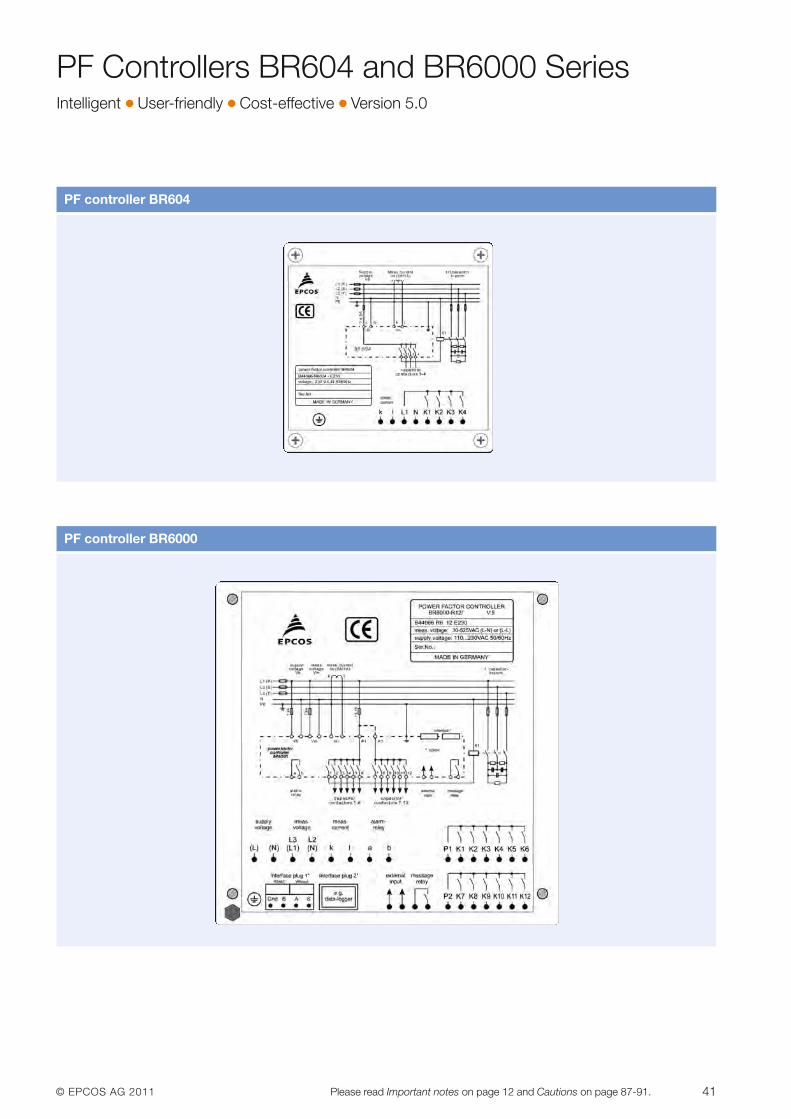
© EPCOS AG 2011 41Please read Important notes on page 12 and Cautions on page 87-91.
PF Controllers BR604 and BR6000 SeriesIntelligent � User-friendly � Cost-effective � Version 5.0
PF controller BR604
PF controller BR6000
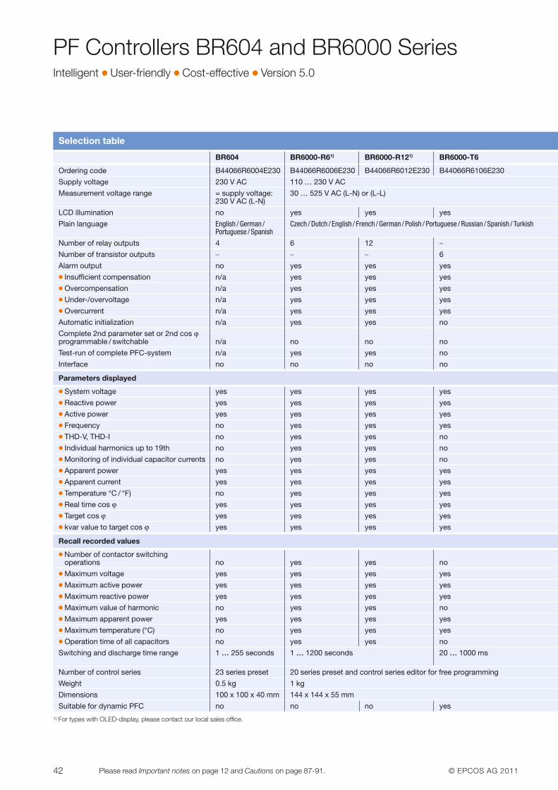
42 © EPCOS AG 2011Please read Important notes on page 12 and Cautions on page 87-91.
PF Controllers BR604 and BR6000 SeriesIntelligent � User-friendly � Cost-effective � Version 5.0
Selection table
BR604 BR6000-R61) BR6000-R121) BR6000-T6
Ordering code B44066R6004E230 B44066R6006E230 B44066R6012E230 B44066R6106E230
Supply voltage 230 V AC 110 … 230 V AC
Measurement voltage range = supply voltage: 30 … 525 V AC (L-N) or (L-L) 230 V AC (L-N)
LCD illumination no yes yes yes
Plain language English / German / Czech / Dutch / English / French / German / Polish / Portuguese / Russian / Spanish / TurkishPortuguese / Spanish
Number of relay outputs 4 6 12 –
Number of transistor outputs – – – 6
Alarm output no yes yes yes� Insufficient compensation n/a yes yes yes� Overcompensation n/a yes yes yes� Under-/overvoltage n/a yes yes yes� Overcurrent n/a yes yes yes
Automatic initialization n/a yes yes no
Complete 2nd parameter set or 2nd cos ϕprogrammable / switchable n/a no no no
Test-run of complete PFC-system n/a yes yes no
Interface no no no no
Parameters displayed
� System voltage yes yes yes yes� Reactive power yes yes yes yes� Active power yes yes yes yes� Frequency no yes yes yes� THD-V, THD-I no yes yes no� Individual harmonics up to 19th no yes yes no� Monitoring of individual capacitor currents no yes yes no� Apparent power yes yes yes yes� Apparent current yes yes yes yes� Temperature °C / °F) no yes yes yes� Real time cos ϕ yes yes yes yes� Target cos ϕ yes yes yes yes� kvar value to target cos ϕ yes yes yes yes
Recall recorded values
� Number of contactor switching operations no yes yes no
� Maximum voltage yes yes yes yes� Maximum active power yes yes yes yes� Maximum reactive power yes yes yes yes� Maximum value of harmonic no yes yes no� Maximum apparent power yes yes yes yes� Maximum temperature (°C) no yes yes yes� Operation time of all capacitors no yes yes no
Switching and discharge time range 1 … 255 seconds 1 … 1200 seconds 20 … 1000 ms
Number of control series 23 series preset 20 series preset and control series editor for free programming
Weight 0.5 kg 1 kg
Dimensions 100 x 100 x 40 mm 144 x 144 x 55 mm
Suitable for dynamic PFC no no no yes
1) For types with OLED-display, please contact our local sales office.
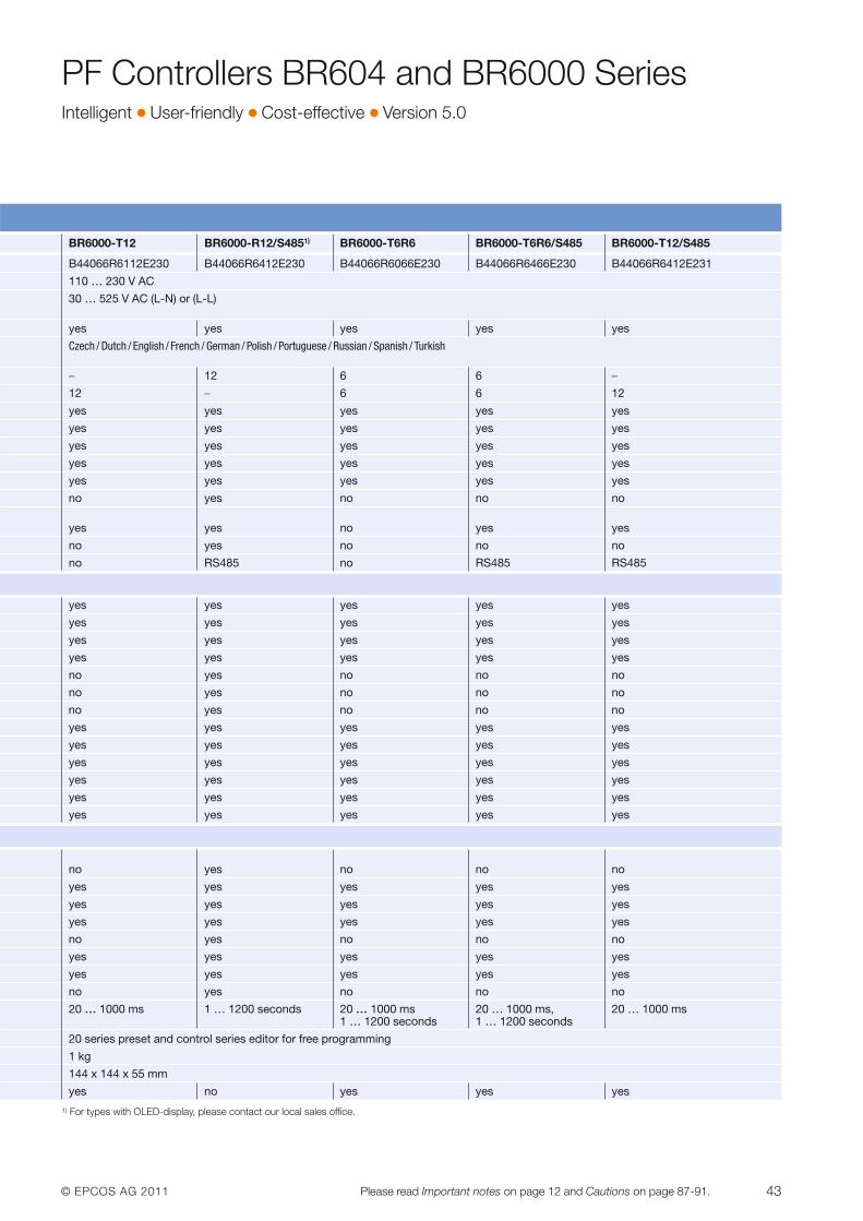
© EPCOS AG 2011 43Please read Important notes on page 12 and Cautions on page 87-91.
PF Controllers BR604 and BR6000 SeriesIntelligent � User-friendly � Cost-effective � Version 5.0
BR6000-T12 BR6000-R12/S4851) BR6000-T6R6 BR6000-T6R6/S485 BR6000-T12/S485
B44066R6112E230 B44066R6412E230 B44066R6066E230 B44066R6466E230 B44066R6412E231
110 … 230 V AC
30 … 525 V AC (L-N) or (L-L)
yes yes yes yes yes
Czech / Dutch / English / French / German / Polish / Portuguese / Russian / Spanish / Turkish
– 12 6 6 –
12 – 6 6 12
yes yes yes yes yes
yes yes yes yes yes
yes yes yes yes yes
yes yes yes yes yes
yes yes yes yes yes
no yes no no no
yes yes no yes yes
no yes no no no
no RS485 no RS485 RS485
yes yes yes yes yes
yes yes yes yes yes
yes yes yes yes yes
yes yes yes yes yes
no yes no no no
no yes no no no
no yes no no no
yes yes yes yes yes
yes yes yes yes yes
yes yes yes yes yes
yes yes yes yes yes
yes yes yes yes yes
yes yes yes yes yes
no yes no no no
yes yes yes yes yes
yes yes yes yes yes
yes yes yes yes yes
no yes no no no
yes yes yes yes yes
yes yes yes yes yes
no yes no no no
20 … 1000 ms 1 … 1200 seconds 20 … 1000 ms 20 … 1000 ms, 20 … 1000 ms1 … 1200 seconds 1 … 1200 seconds
20 series preset and control series editor for free programming
1 kg
144 x 144 x 55 mm
yes no yes yes yes
1) For types with OLED-display, please contact our local sales office.
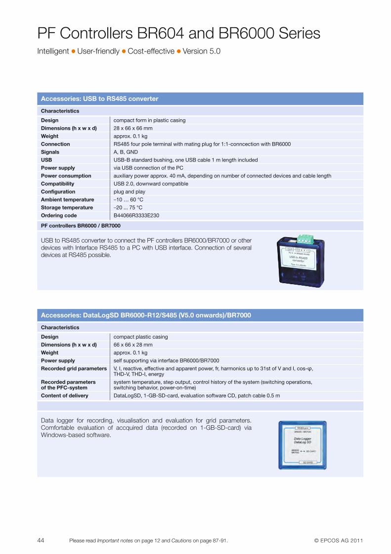
44 © EPCOS AG 2011Please read Important notes on page 12 and Cautions on page 87-91.
Accessories: USB to RS485 converter
USB to RS485 converter to connect the PF controllers BR6000/BR7000 or other devices with Interface RS485 to a PC with USB interface. Connection of several devices at RS485 possible.
Characteristics
Design compact form in plastic casing
Dimensions (h x w x d) 28 x 66 x 66 mm
Weight approx. 0.1 kg
Connection RS485 four pole terminal with mating plug for 1:1-conncection with BR6000
Signals A, B, GND
USB USB-B standard bushing, one USB cable 1 m length included
Power supply via USB connection of the PC
Power consumption auxiliary power approx. 40 mA, depending on number of connected devices and cable length
Compatibility USB 2.0, downward compatible
Configuration plug and play
Ambient temperature –10 … 60 °C
Storage temperature –20 ... 75 °C
Ordering code B44066R3333E230
PF controllers BR6000 / BR7000
Accessories: DataLogSD BR6000-R12/S485 (V5.0 onwards)/BR7000
Data logger for recording, visualisation and evaluation for grid parameters. Comfortable evaluation of accquired data (recorded on 1-GB-SD-card) via Windows-based software.
Characteristics
Design compact plastic casing
Dimensions (h x w x d) 66 x 66 x 28 mm
Weight approx. 0.1 kg
Power supply self supporting via interface BR6000/BR7000
Recorded grid parameters V, I, reactive, effective and apparent power, fr, harmonics up to 31st of V and I, cos-φ, THD-V, THD-I, energy
Recorded parameters system temperature, step output, control history of the system (switching operations, of the PFC-system switching behavior, power-on-time)
Content of delivery DataLogSD, 1-GB-SD-card, evaluation software CD, patch cable 0.5 m
PF Controllers BR604 and BR6000 SeriesIntelligent � User-friendly � Cost-effective � Version 5.0
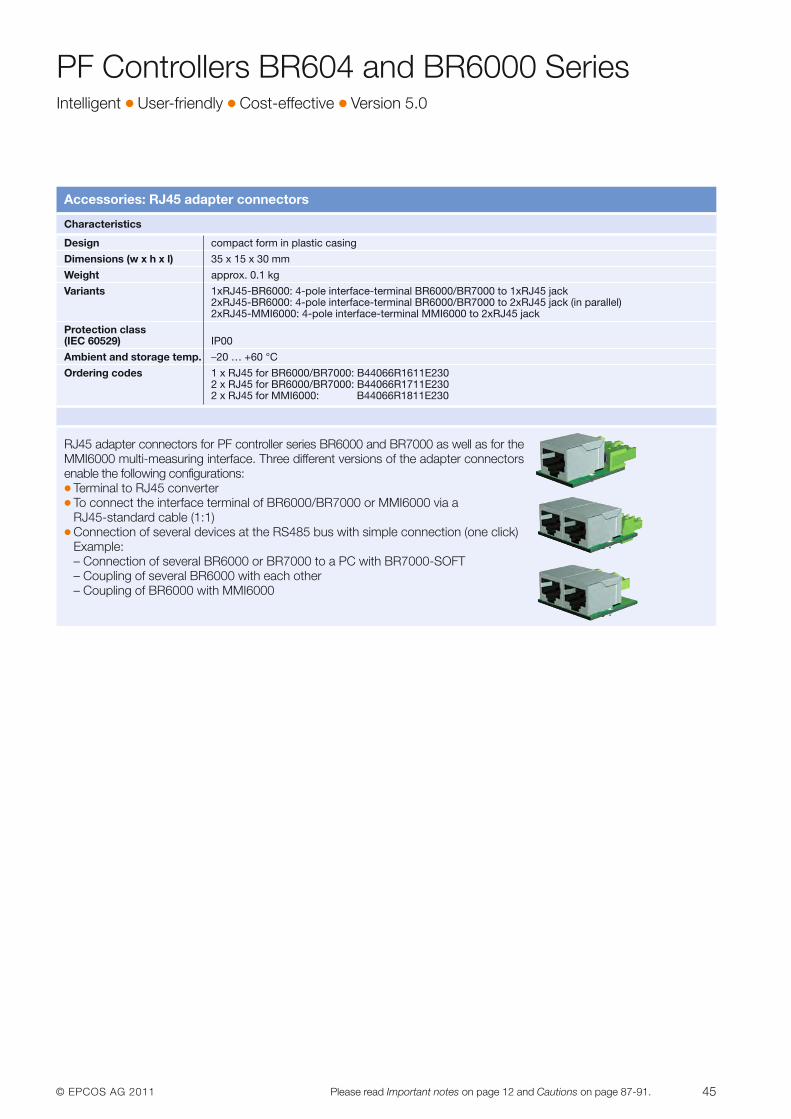
© EPCOS AG 2011 45Please read Important notes on page 12 and Cautions on page 87-91.
Accessories: RJ45 adapter connectors
RJ45 adapter connectors for PF controller series BR6000 and BR7000 as well as for theMMI6000 multi-measuring interface. Three different versions of the adapter connectors enable the following configurations:� Terminal to RJ45 converter� To connect the interface terminal of BR6000/BR7000 or MMI6000 via a
RJ45-standard cable (1:1)� Connection of several devices at the RS485 bus with simple connection (one click)
Example:– Connection of several BR6000 or BR7000 to a PC with BR7000-SOFT– Coupling of several BR6000 with each other– Coupling of BR6000 with MMI6000
Characteristics
Design compact form in plastic casing
Dimensions (w x h x l) 35 x 15 x 30 mm
Weight approx. 0.1 kg
Variants 1xRJ45-BR6000: 4-pole interface-terminal BR6000/BR7000 to 1xRJ45 jack2xRJ45-BR6000: 4-pole interface-terminal BR6000/BR7000 to 2xRJ45 jack (in parallel)2xRJ45-MMI6000: 4-pole interface-terminal MMI6000 to 2xRJ45 jack
Protection class(IEC 60529) IP00
Ambient and storage temp. –20 … +60 °C
Ordering codes 1 x RJ45 for BR6000/BR7000: B44066R1611E2302 x RJ45 for BR6000/BR7000: B44066R1711E2302 x RJ45 for MMI6000: B44066R1811E230
PF Controllers BR604 and BR6000 SeriesIntelligent � User-friendly � Cost-effective � Version 5.0
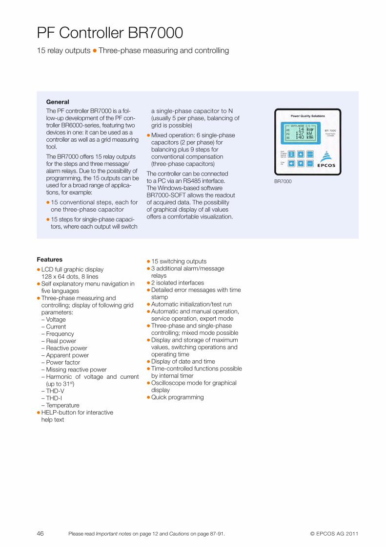
46 © EPCOS AG 2011Please read Important notes on page 12 and Cautions on page 87-91.
PF Controller BR700015 relay outputs � Three-phase measuring and controlling
GeneralThe PF controller BR7000 is a fol-low-up development of the PF con-troller BR6000-series, featuring twodevices in one: it can be used as acontroller as well as a grid measuringtool.
The BR7000 offers 15 relay outputsfor the steps and three message/alarm relays. Due to the possibility ofprogramming, the 15 outputs can beused for a broad range of applica-tions, for example:
� 15 conventional steps, each forone three-phase capacitor
� 15 steps for single-phase capaci-tors, where each output will switch
a single-phase capacitor to N(usually 5 per phase, balancing ofgrid is possible)
� Mixed operation: 6 single-phasecapacitors (2 per phase) for balancing plus 9 steps for conventional compensation(three-phase capacitors)
The controller can be connected to a PC via an RS485 interface. The Windows-based softwareBR7000-SOFT allows the readoutof acquired data. The possibility of graphical display of all values offers a comfortable visualization.
BR7000
Features
� LCD full graphic display128 x 64 dots, 8 lines
� Self explanatory menu navigation infive languages
� Three-phase measuring and controlling; display of following gridparameters:– Voltage – Current– Frequency– Real power– Reactive power– Apparent power– Power factor– Missing reactive power– Harmonic of voltage and current
(up to 31st)– THD-V– THD-I– Temperature
� HELP-button for interactive help text
� 15 switching outputs� 3 additional alarm/message
relays� 2 isolated interfaces� Detailed error messages with time
stamp� Automatic initialization/test run� Automatic and manual operation,
service operation, expert mode� Three-phase and single-phase
controlling; mixed mode possible� Display and storage of maximum
values, switching operations andoperating time
� Display of date and time� Time-controlled functions possible
by internal timer� Oscilloscope mode for graphical
display� Quick programming
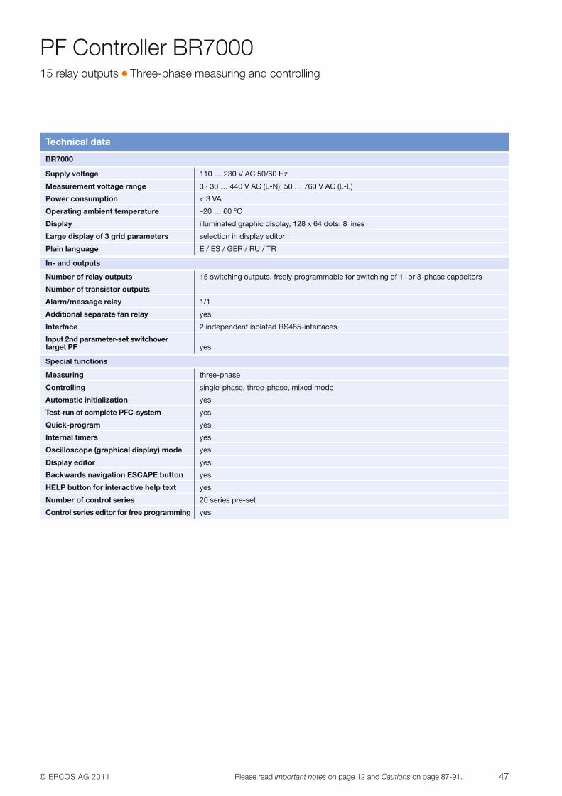
© EPCOS AG 2011 47Please read Important notes on page 12 and Cautions on page 87-91.
PF Controller BR700015 relay outputs � Three-phase measuring and controlling
Technical data
BR7000
Supply voltage 110 … 230 V AC 50/60 Hz
Measurement voltage range 3 · 30 … 440 V AC (L-N); 50 … 760 V AC (L-L)
Power consumption < 3 VA
Operating ambient temperature –20 … 60 °C
Display illuminated graphic display, 128 x 64 dots, 8 lines
Large display of 3 grid parameters selection in display editor
Plain language E / ES / GER / RU / TR
In- and outputs
Number of relay outputs 15 switching outputs, freely programmable for switching of 1- or 3-phase capacitors
Number of transistor outputs –
Alarm/message relay 1/1
Additional separate fan relay yes
Interface 2 independent isolated RS485-interfaces
Input 2nd parameter-set switchover target PF yes
Special functions
Measuring three-phase
Controlling single-phase, three-phase, mixed mode
Automatic initialization yes
Test-run of complete PFC-system yes
Quick-program yes
Internal timers yes
Oscilloscope (graphical display) mode yes
Display editor yes
Backwards navigation ESCAPE button yes
HELP button for interactive help text yes
Number of control series 20 series pre-set
Control series editor for free programming yes
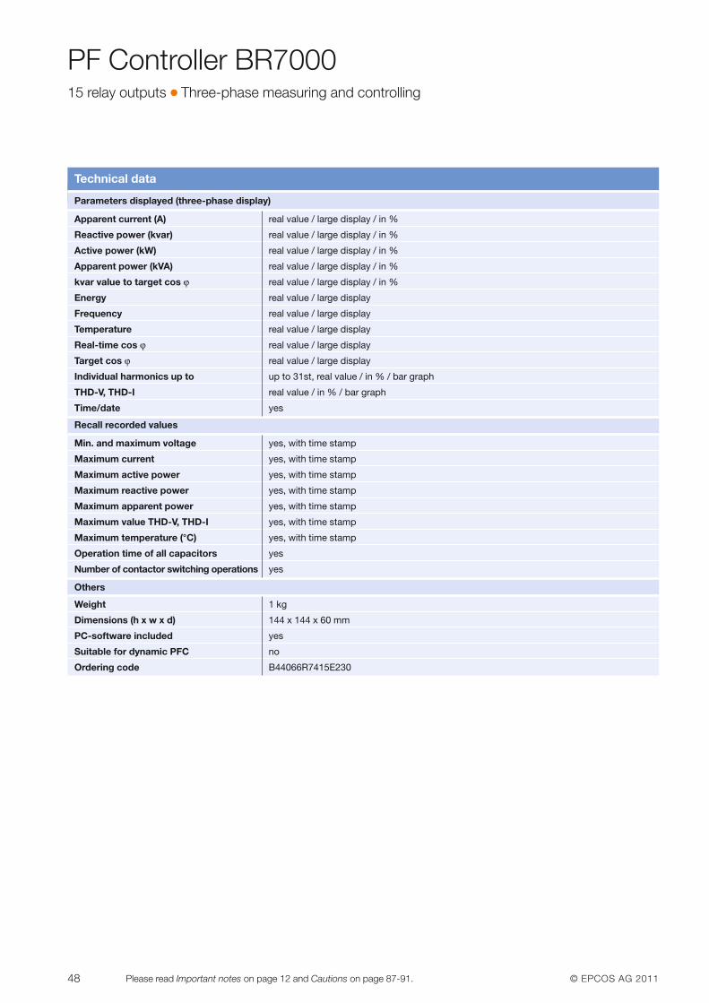
48 © EPCOS AG 2011Please read Important notes on page 12 and Cautions on page 87-91.
PF Controller BR700015 relay outputs � Three-phase measuring and controlling
Technical data
Parameters displayed (three-phase display)
Apparent current (A) real value / large display / in %
Reactive power (kvar) real value / large display / in %
Active power (kW) real value / large display / in %
Apparent power (kVA) real value / large display / in %
kvar value to target cos ϕ real value / large display / in %
Energy real value / large display
Frequency real value / large display
Temperature real value / large display
Real-time cos ϕ real value / large display
Target cos ϕ real value / large display
Individual harmonics up to up to 31st, real value / in % / bar graph
THD-V, THD-I real value / in % / bar graph
Time/date yes
Recall recorded values
Min. and maximum voltage yes, with time stamp
Maximum current yes, with time stamp
Maximum active power yes, with time stamp
Maximum reactive power yes, with time stamp
Maximum apparent power yes, with time stamp
Maximum value THD-V, THD-I yes, with time stamp
Maximum temperature (°C) yes, with time stamp
Operation time of all capacitors yes
Number of contactor switching operations yes
Others
Weight 1 kg
Dimensions (h x w x d) 144 x 144 x 60 mm
PC-software included yes
Suitable for dynamic PFC no
Ordering code B44066R7415E230
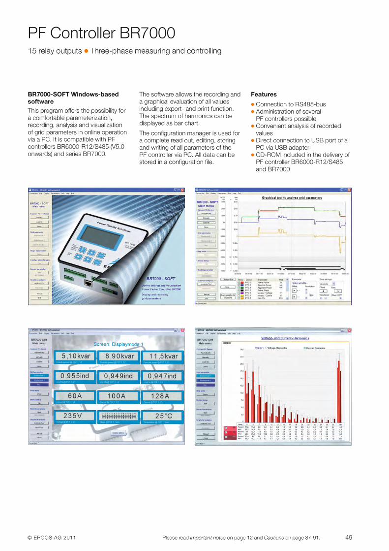
© EPCOS AG 2011 49Please read Important notes on page 12 and Cautions on page 87-91.
PF Controller BR700015 relay outputs � Three-phase measuring and controlling
BR7000-SOFT Windows-basedsoftwareThis program offers the possibility fora comfortable parameterization,recording, analysis and visualization of grid parameters in online operationvia a PC. It is compatible with PF controllers BR6000-R12/S485 (V5.0onwards) and series BR7000.
The software allows the recording anda graphical evaluation of all values including export- and print function.The spectrum of harmonics can bedisplayed as bar chart.
The configuration manager is used fora complete read out, editing, storingand writing of all parameters of the PF controller via PC. All data can bestored in a configuration file.
Features
� Connection to RS485-bus� Administration of several
PF controllers possible� Convenient analysis of recorded
values� Direct connection to USB port of a
PC via USB adapter� CD-ROM included in the delivery of
PF controller BR6000-R12/S485and BR7000
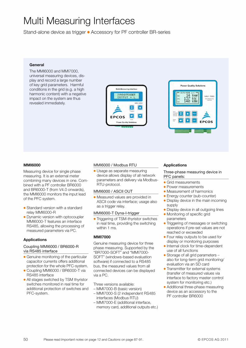
50 © EPCOS AG 2011Please read Important notes on page 12 and Cautions on page 87-91.
Multi Measuring InterfacesStand-alone device as trigger � Accessory for PF controller BR-series
General
The MMI6000 and MMI7000, universal measuring devices, dis-play and record a large number of key grid parameters. Harmfulconditions in the grid (e.g. a highharmonic content) with a negativeimpact on the system are thus revealed immediately.
MMI6000
Measuring device for single phasemeasuring. It is an external metercombining many devices in one. Com-bined with a PF controller BR6000and BR6000-T (from V4.0 onwards),the MMI6000 monitors the input leadof the PFC system.
� Standard version with a standard relay MMI6000-R
� Dynamic version with optocouplerMMI6000-T features an interfaceRS485, allowing the processing ofmeasured parameters via PC.
Applications
Coupling MMI6000 / BR6000-R via RS485 interface� Genuine monitoring of the particular
capacitor currents offers additionalprotection for the whole PFC-system.
� Coupling MMI6000 / BR6000-T viaRS485 interface
� All stages switched by TSM thyristorswitches monitored in real time foradditional protection of switches andPFC-system.
MMI6000 / Modbus RTU� Usage as separate measuring
device allows display of all networkparameters and delivery via Modbus-RTU-protocol.
MMI6000 / ASCII OUT� Measured values are provided in
ASCII code via interface; usage alsoas a trigger relay.
MMI6000-T Dyna-I-trigger� Triggering of TSM-thyristor switches
in real time, providing the switchingwithin 1 ms.
MMI7000
Genuine measuring device for threephase measuring. Supported by the“BR7000-SOFT” and “MMI7000-SOFT” (windows-based evaluationsoftware) if connected to a RS485bus, the measured values from allconnected devices can be displayedvia a PC.
Three versions available: – MMI7000-B (basic version)– MMI7000-S (2 independent RS485
interfaces (Modbus RTU)– MMI7000-E (additional interface,
memory card, additional outputs etc.)
Applications
Three-phase measuring device inPFC panels:� Grid measurements� Power measurements� Measurement of harmonics� Energy counter (sub-counter)� Display device in the main incoming
supply� Display device in all outgoing lines� Monitoring of specific grid
parameters� Triggering of messages or switching
operations if pre-set values are notreached or exceeded
� Four relay outputs to be used fordisplay or monitoring purposes
� Internal clock for time-dependentuse of all functions
� Storage of all grid parameters – also for long-term grid monitoring/evaluation via an SD card
� Transmitter for external systems(transfer of measured values viainterface to factory master controlsystem for monitoring etc.)
� Additional three-phase measuringdevice as an accessory to the PF controller BR6000
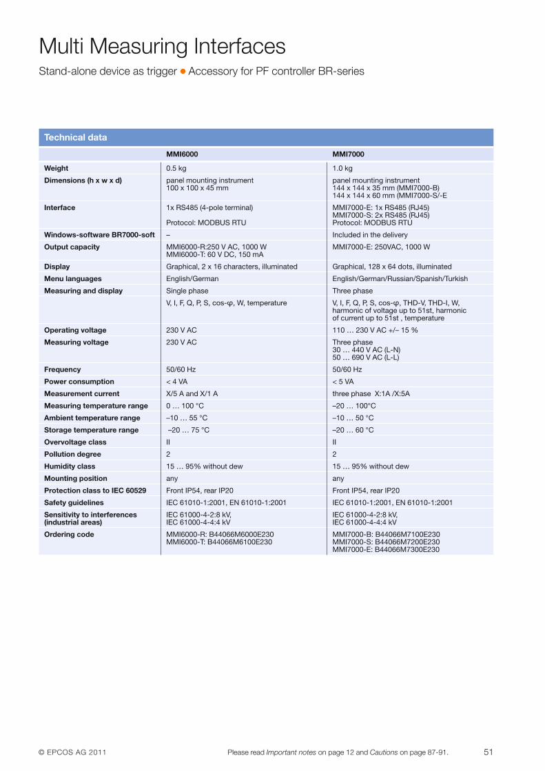
© EPCOS AG 2011 51Please read Important notes on page 12 and Cautions on page 87-91.
Multi Measuring InterfacesStand-alone device as trigger � Accessory for PF controller BR-series
Technical data
MMI6000 MMI7000
Weight 0.5 kg 1.0 kg
Dimensions (h x w x d) panel mounting instrument panel mounting instrument 100 x 100 x 45 mm 144 x 144 x 35 mm (MMI7000-B)
144 x 144 x 60 mm (MMI7000-S/-E
Interface 1x RS485 (4-pole terminal) MMI7000-E: 1x RS485 (RJ45)MMI7000-S: 2x RS485 (RJ45)
Protocol: MODBUS RTU Protocol: MODBUS RTU
Windows-software BR7000-soft – Included in the delivery
Output capacity MMI6000-R:250 V AC, 1000 W MMI7000-E: 250VAC, 1000 WMMI6000-T: 60 V DC, 150 mA
Display Graphical, 2 x 16 characters, illuminated Graphical, 128 x 64 dots, illuminated
Menu languages English/German English/German/Russian/Spanish/Turkish
Measuring and display Single phase Three phase
V, I, F, Q, P, S, cos-φ, W, temperature V, I, F, Q, P, S, cos-φ, THD-V, THD-I, W, harmonic of voltage up to 51st, harmonic of current up to 51st , temperature
Operating voltage 230 V AC 110 … 230 V AC +/– 15 %
Measuring voltage 230 V AC Three phase30 … 440 V AC (L-N)50 … 690 V AC (L-L)
Frequency 50/60 Hz 50/60 Hz
Power consumption < 4 VA < 5 VA
Measurement current X/5 A and X/1 A three phase X:1A /X:5A
Measuring temperature range 0 … 100 °C –20 … 100°C
Ambient temperature range –10 … 55 °C –10 … 50 °C
Storage temperature range –20 … 75 °C –20 … 60 °C
Overvoltage class II II
Pollution degree 2 2
Humidity class 15 … 95% without dew 15 … 95% without dew
Mounting position any any
Protection class to IEC 60529 Front IP54, rear IP20 Front IP54, rear IP20
Safety guidelines IEC 61010-1:2001, EN 61010-1:2001 IEC 61010-1:2001, EN 61010-1:2001
Sensitivity to interferences IEC 61000-4-2:8 kV, IEC 61000-4-2:8 kV,(industrial areas) IEC 61000-4-4:4 kV IEC 61000-4-4:4 kV
Ordering code MMI6000-R: B44066M6000E230 MMI7000-B: B44066M7100E230MMI6000-T: B44066M6100E230 MMI7000-S: B44066M7200E230
MMI7000-E: B44066M7300E230
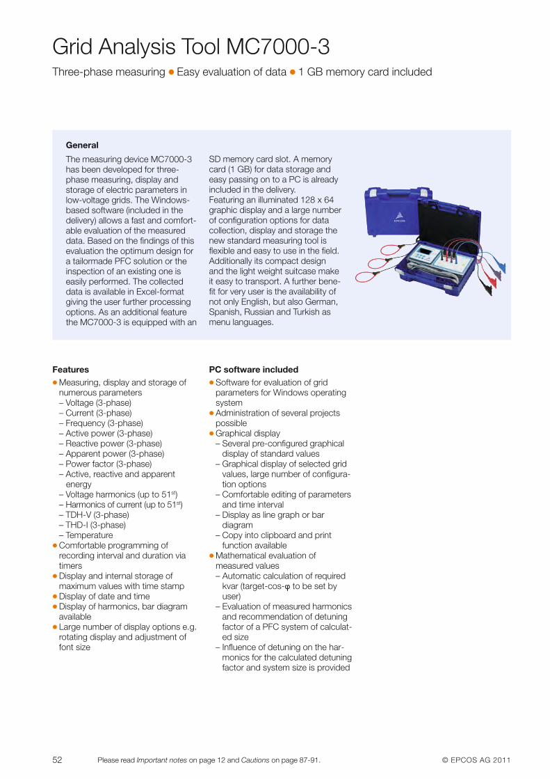
52 © EPCOS AG 2011Please read Important notes on page 12 and Cautions on page 87-91.
Grid Analysis Tool MC7000-3Three-phase measuring � Easy evaluation of data � 1 GB memory card included
General
The measuring device MC7000-3has been developed for three-phase measuring, display andstorage of electric parameters inlow-voltage grids. The Windows-based software (included in the delivery) allows a fast and comfort-able evaluation of the measureddata. Based on the findings of thisevaluation the optimum design fora tailormade PFC solution or theinspection of an existing one iseasily performed. The collecteddata is available in Excel-formatgiving the user further processingoptions. As an additional featurethe MC7000-3 is equipped with an
SD memory card slot. A memorycard (1 GB) for data storage andeasy passing on to a PC is alreadyincluded in the delivery.Featuring an illuminated 128 x 64graphic display and a large numberof configuration options for datacollection, display and storage thenew standard measuring tool is flexible and easy to use in the field.Additionally its compact designand the light weight suitcase makeit easy to transport. A further bene-fit for very user is the availability ofnot only English, but also German,Spanish, Russian and Turkish asmenu languages.
Features� Measuring, display and storage of
numerous parameters– Voltage (3-phase)– Current (3-phase)– Frequency (3-phase)– Active power (3-phase)– Reactive power (3-phase)– Apparent power (3-phase)– Power factor (3-phase)– Active, reactive and apparent
energy– Voltage harmonics (up to 51st)– Harmonics of current (up to 51st)– TDH-V (3-phase)– THD-I (3-phase)– Temperature
� Comfortable programming ofrecording interval and duration viatimers
� Display and internal storage of maximum values with time stamp
� Display of date and time� Display of harmonics, bar diagram
available� Large number of display options e.g.
rotating display and adjustment offont size
PC software included� Software for evaluation of grid
parameters for Windows operatingsystem
� Administration of several projectspossible
� Graphical display– Several pre-configured graphical
display of standard values– Graphical display of selected grid
values, large number of configura-tion options
– Comfortable editing of para metersand time interval
– Display as line graph or bar diagram
– Copy into clipboard and print function available
� Mathematical evaluation of measured values– Automatic calculation of required
kvar (target-cos-f to be set byuser)
– Evaluation of measured harmonicsand recommendation of detuningfactor of a PFC system of calculat-ed size
– Influence of detuning on the har-monics for the calculated detuningfactor and system size is provided
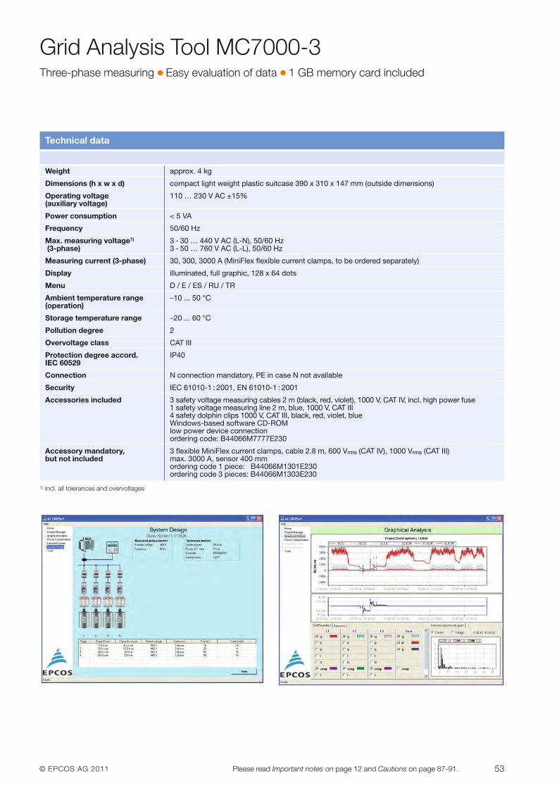
© EPCOS AG 2011 53Please read Important notes on page 12 and Cautions on page 87-91.
Grid Analysis Tool MC7000-3Three-phase measuring � Easy evaluation of data � 1 GB memory card included
Technical data
Weight approx. 4 kg
Dimensions (h x w x d) compact light weight plastic suitcase 390 x 310 x 147 mm (outside dimensions)
Operating voltage 110 … 230 V AC ±15%(auxiliary voltage)
Power consumption < 5 VA
Frequency 50/60 Hz
Max. measuring voltage1) 3 · 30 … 440 V AC (L-N), 50/60 Hz(3-phase) 3 · 50 … 760 V AC (L-L), 50/60 Hz
Measuring current (3-phase) 30, 300, 3000 A (MiniFlex flexible current clamps, to be ordered separately)
Display illuminated, full graphic, 128 x 64 dots
Menu D / E / ES / RU / TR
Ambient temperature range –10 ... 50 °C(operation)
Storage temperature range –20 ... 60 °C
Pollution degree 2
Overvoltage class CAT III
Protection degree accord. IP40IEC 60529
Connection N connection mandatory, PE in case N not available
Security IEC 61010-1 : 2001, EN 61010-1 : 2001
Accessories included 3 safety voltage measuring cables 2 m (black, red, violet), 1000 V, CAT IV, incl. high power fuse1 safety voltage measuring line 2 m, blue, 1000 V, CAT III4 safety dolphin clips 1000 V, CAT III, black, red, violet, blueWindows-based software CD-ROMlow power device connectionordering code: B44066M7777E230
Accessory mandatory, 3 flexible MiniFlex current clamps, cable 2.8 m, 600 Vrms (CAT IV), 1000 Vrms (CAT III)but not included max. 3000 A, sensor 400 mm
ordering code 1 piece: B44066M1301E230ordering code 3 pieces: B44066M1303E230
1) Incl. all tolerances and overvoltages
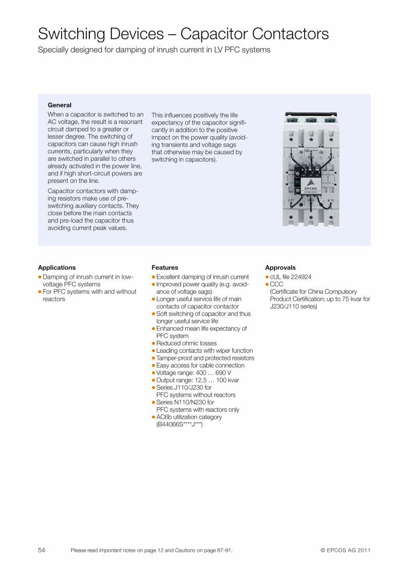
54 © EPCOS AG 2011Please read Important notes on page 12 and Cautions on page 87-91.
Switching Devices – Capacitor ContactorsSpecially designed for damping of inrush current in LV PFC systems
GeneralWhen a capacitor is switched to anAC voltage, the result is a resonantcircuit damped to a greater or lesser degree. The switching of capacitors can cause high inrushcurrents, particularly when they are switched in parallel to othersalready activated in the power line,and if high short-circuit powers arepresent on the line.
Capacitor contactors with damp-ing resistors make use of pre-switching auxiliary contacts. Theyclose before the main contactsand pre-load the capacitor thusavoiding current peak values.
This influences positively the life expectancy of the capacitor signifi-cantly in addition to the positiveimpact on the power quality (avoid-ing transients and voltage sagsthat otherwise may be caused byswitching in capacitors).
Applications� Damping of inrush current in low-
voltage PFC systems� For PFC systems with and without
reactors
Features� Excellent damping of inrush current� Improved power quality (e.g. avoid-
ance of voltage sags)� Longer useful service life of main
contacts of capacitor contactor� Soft switching of capacitor and thus
longer useful service life� Enhanced mean life expectancy of
PFC system� Reduced ohmic losses� Leading contacts with wiper function� Tamper-proof and protected resistors� Easy access for cable connection� Voltage range: 400 … 690 V� Output range: 12.5 … 100 kvar� Series J110/J230 for
PFC systems without reactors� Series N110/N230 for
PFC systems with reactors only� AC6b utilization category
(B44066S****J***)
Approvals� cUL file 224924� CCC
(Certificate for China CompulsoryProduct Certification; up to 75 kvar forJ230/J110 series)
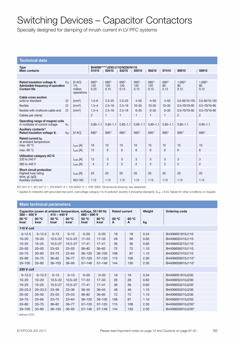
© EPCOS AG 2011 55Please read Important notes on page 12 and Cautions on page 87-91.
Switching Devices – Capacitor ContactorsSpecially designed for damping of inrush current in LV PFC systems
Technical data
Type B44066*****J230/J110/N230/N110Main contacts S1810 S2410 S3210 S5010 S6210 S7410 S9010 S9910
Rated insulation voltage VI VIS [V AC] 6901) 6901) 6901) 6901) 6901) 6901) 1,0001) 1,0001)
Admissible frequency of operation 1/h 120 120 120 120 120 80 80 80Contact life million 0.25 0.15 0.15 0.15 0.15 0.12 0.12 0.12
operations
Cable cross sectionsolid or standard [mm2] 1.5–6 2.5–25 2.5–25 4–50 4–50 4–50 0.5–95/10–120 0.5–95/10–120
flexible [mm2] 1.5–4 2.5–16 2.5–16 10–35 10–35 10–35 0.5–70/10–95 0.5–70/10–95
flexible with multicore cable end [mm2] 1.5–4 2.5–16 2.5–16 6–35 6–35 6–35 0.5–70/10–95 0.5–70/10–95
Cables per clamp 2 1 1 1 1 1 2 2
Operating range of magnet coilsin multiples of control voltage VS 0.85–1.1 0.85–1.1 0.85–1.1 0.85–1.1 0.85–1.1 0.85–1.1 0.85–1.1 0.85–1.1
Auxiliary contacts1)
Rated insulation voltage VI VIS [V AC] 6901) 6901) 6901) 6901) 6901) 6901) 6901) 6901)
Rated current Ithat ambient temperaturemax. 40 °C Icoth [A] 16 10 10 10 10 10 10 10
max. 60 °C Icoth [A] 12 6 6 6 6 6 6 6
Utilization category AC15220 to 240 V Icoth [A] 12 3 3 3 3 3 3 3
380 to 440 V Icoth [A] 4 2 2 2 2 2 2 2
Short circuit protectionHighest fuse rating Icoth [A] 25 20 20 20 20 20 20 20slow, gL (gG)Auxiliary contacts NO / NC 1 / 0 1 / 0 1 / 0 1 / 0 1 / 0 1 / 0 1 / 0 1 / 0
IEC 947-4-1, IEC 947-5-1, EN 60947-4-1, EN 60947-5-1, VDE 0660. Dimensional drawing: see datasheet1) Applies to networks with grounded star point, overvoltage category I to IV, pollution severity 3 (industrial standard), Vimp = 8 kV. Values for other conditions on request.
Main technical parameters
Capacitor power at ambient temperature, voltage, 50 / 60 Hz Rated current Weight Ordering code380 – 400 V 415 – 440 V 660 – 690 V50 ºC 60 ºC 50 ºC 60 ºC 50 ºC 60 ºC 50 ºC 60 ºCkvar kvar kvar kvar kvar kvar A A kg
110 V coil
0–12.5 0–12.5 0–13 0–13 0–20 0–20 18 18 0.34 B44066S1810J110
10–20 10–20 10.5–22 10.5–22 17–33 17–33 28 28 0.60 B44066S2410J110
10–25 10–25 10.5–27 10.5–27 17–41 17–41 36 36 0.60 B44066S3210J110
20–50 20–50 23–53 23–53 36–82 36–82 72 72 1.10 B44066S6210J110
20–75 20–60 23–75 23–64 36–120 36–100 108 87 1.10 B44066S7410J110
33–80 33–75 36–82 36–77 57–120 57–120 115 108 2.30 B44066S9010J110*
33–100 33–90 36–103 36–93 57–148 57–148 144 130 2.30 B44066S9910J110*
230 V coil
0–12.5 0–12.5 0–13 0–13 0–20 0–20 18 18 0.34 B44066S1810J230
10–20 10–20 10.5–22 10.5–22 17–33 17–33 28 28 0.60 B44066S2410J230
10–25 10–25 10.5–27 10.5–27 17–41 17–41 36 36 0.60 B44066S3210J230
20–33.3 20–33.3 23–36 23–36 36–55 36–55 48 48 1.10 B44066S5010J230
20–50 20–50 23–53 23–53 36–82 36–82 72 72 1.10 B44066S6210J230
20–75 20–60 23–75 23–64 36–120 36–100 108 87 1.10 B44066S7410J230
33–80 33–75 36–82 36–77 57–120 57–120 115 108 2.30 B44066S9010J230*
33–100 33–90 36–103 36–93 57–148 57–148 144 130 2.30 B44066S9910J230*
* without CCC
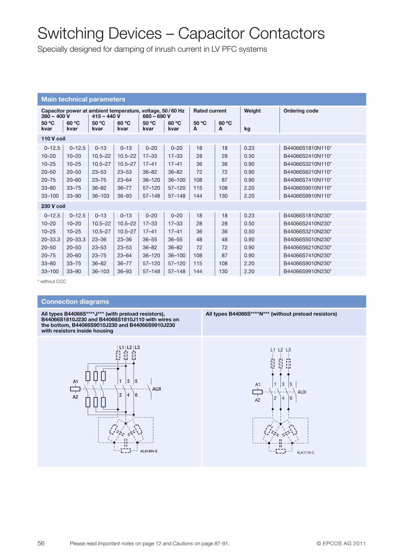
56 © EPCOS AG 2011Please read Important notes on page 12 and Cautions on page 87-91.
Switching Devices – Capacitor ContactorsSpecially designed for damping of inrush current in LV PFC systems
Main technical parameters
Capacitor power at ambient temperature, voltage, 50 / 60 Hz Rated current Weight Ordering code380 – 400 V 415 – 440 V 660 – 690 V50 ºC 60 ºC 50 ºC 60 ºC 50 ºC 60 ºC 50 ºC 60 ºCkvar kvar kvar kvar kvar kvar A A kg
110 V coil
0–12.5 0–12.5 0–13 0–13 0–20 0–20 18 18 0.23 B44066S1810N110*
10–20 10–20 10.5–22 10.5–22 17–33 17–33 28 28 0.50 B44066S2410N110*
10–25 10–25 10.5–27 10.5–27 17–41 17–41 36 36 0.90 B44066S3210N110*
20–50 20–50 23–53 23–53 36–82 36–82 72 72 0.90 B44066S6210N110*
20–75 20–60 23–75 23–64 36–120 36–100 108 87 0.90 B44066S7410N110*
33–80 33–75 36–82 36–77 57–120 57–120 115 108 2.20 B44066S9010N110*
33–100 33–90 36–103 36–93 57–148 57–148 144 130 2.20 B44066S9910N110*
230 V coil
0–12.5 0–12.5 0–13 0–13 0–20 0–20 18 18 0.23 B44066S1810N230*
10–20 10–20 10.5–22 10.5–22 17–33 17–33 28 28 0.50 B44066S2410N230*
10–25 10–25 10.5–27 10.5–27 17–41 17–41 36 36 0.50 B44066S3210N230*
20–33.3 20–33.3 23–36 23–36 36–55 36–55 48 48 0.90 B44066S5010N230*
20–50 20–50 23–53 23–53 36–82 36–82 72 72 0.90 B44066S6210N230*
20–75 20–60 23–75 23–64 36–120 36–100 108 87 0.90 B44066S7410N230*
33–80 33–75 36–82 36–77 57–120 57–120 115 108 2.20 B44066S9010N230*
33–100 33–90 36–103 36–93 57–148 57–148 144 130 2.20 B44066S9910N230*
Connection diagrams
All types B44066S****J*** (with preload resistors), B44066S1810J230 and B44066S1810J110 with wires on the bottom, B44066S9010J230 and B44066S9910J230 with resistors inside housing
KLK1694-E
1
2
3
4
5
6
A1
A2
L1 L2 L3
AUX
KLK1779-C
1
2
3
4
5
6
A1
A2
L1 L2 L3
AUX
All types B44066S****N*** (without preload resistors)
* without CCC
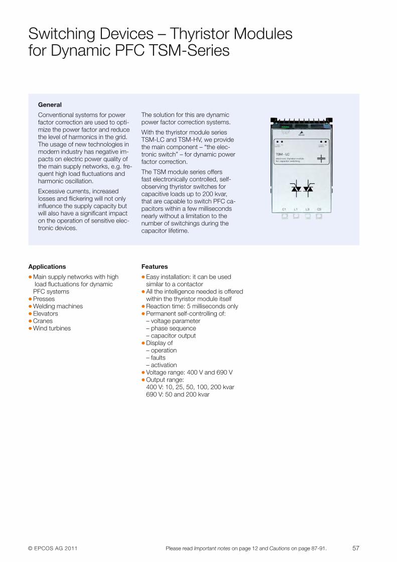
© EPCOS AG 2011 57Please read Important notes on page 12 and Cautions on page 87-91.
Switching Devices – Thyristor Modules for Dynamic PFC TSM-Series
General
Conventional systems for powerfactor correction are used to opti-mize the power factor and reducethe level of harmonics in the grid.The usage of new technologies inmodern industry has negative im-pacts on electric power quality ofthe main supply networks, e.g. fre-quent high load fluctuations andharmonic oscillation.
Excessive currents, increased losses and flickering will not onlyinfluence the supply capacity butwill also have a significant impacton the operation of sensitive elec-tronic devices.
The solution for this are dynamicpower factor correction systems.
With the thyristor module seriesTSM-LC and TSM-HV, we providethe main component – “the elec-tronic switch” – for dynamic powerfactor correction.
The TSM module series offers fast electronically controlled, self-observing thyristor switches for capacitive loads up to 200 kvar,that are capable to switch PFC ca-pacitors within a few millisecondsnearly without a limitation to thenumber of switchings during thecapacitor lifetime.
Applications
� Main supply networks with highload fluctuations for dynamic PFC systems
� Presses� Welding machines� Elevators� Cranes� Wind turbines
Features
� Easy installation: it can be used similar to a contactor
� All the intelligence needed is offeredwithin the thyristor module itself
� Reaction time: 5 milliseconds only� Permanent self-controlling of:
– voltage parameter– phase sequence– capacitor output
� Display of– operation– faults– activation
� Voltage range: 400 V and 690 V� Output range:
400 V: 10, 25, 50, 100, 200 kvar 690 V: 50 and 200 kvar
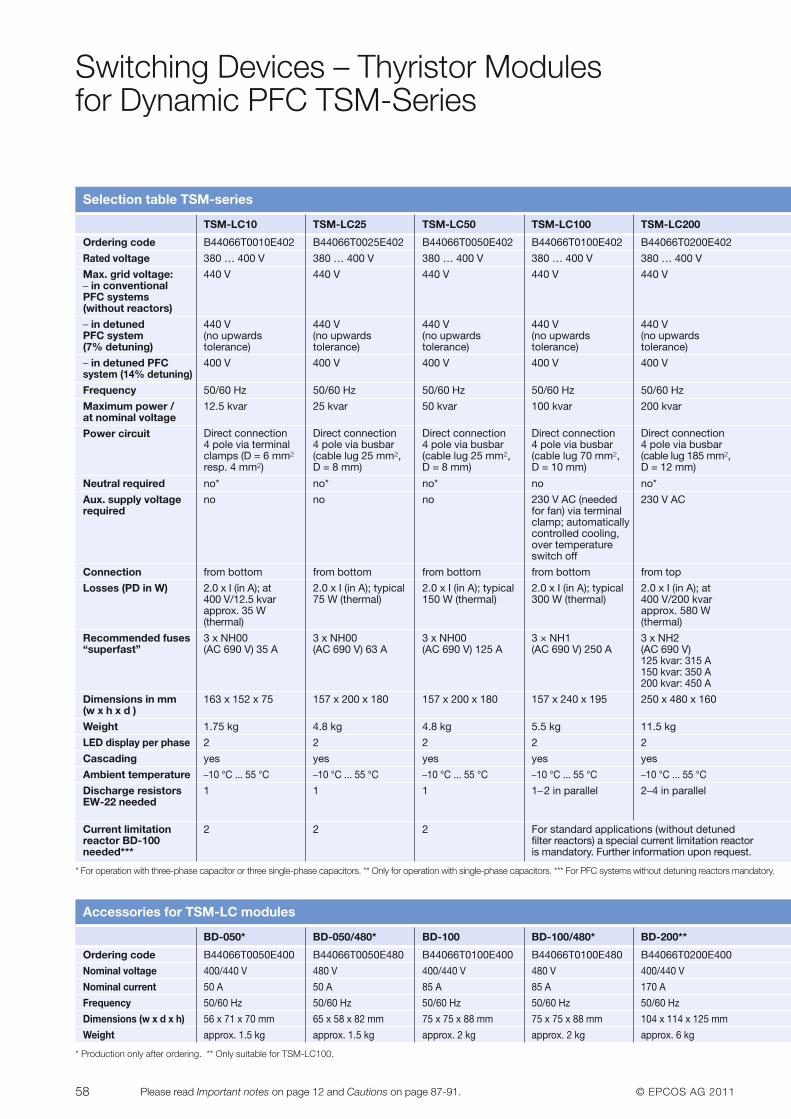
58 © EPCOS AG 2011Please read Important notes on page 12 and Cautions on page 87-91.
Switching Devices – Thyristor Modules for Dynamic PFC TSM-Series
Selection table TSM-series
* For operation with three-phase capacitor or three single-phase capacitors. ** Only for operation with single-phase capacitors. *** For PFC systems without detuning reactors mandatory.
* Production only after ordering. ** Only suitable for TSM-LC100.
TSM-LC10 TSM-LC25 TSM-LC50 TSM-LC100 TSM-LC200
Ordering code B44066T0010E402 B44066T0025E402 B44066T0050E402 B44066T0100E402 B44066T0200E402
Rated voltage 380 … 400 V 380 … 400 V 380 … 400 V 380 … 400 V 380 … 400 V
Max. grid voltage: 440 V 440 V 440 V 440 V 440 V– in conventional PFC systems (without reactors)
– in detuned 440 V 440 V 440 V 440 V 440 VPFC system (no upwards (no upwards (no upwards (no upwards (no upwards (7% detuning) tolerance) tolerance) tolerance) tolerance) tolerance)
– in detuned PFC 400 V 400 V 400 V 400 V 400 Vsystem (14% detuning)
Frequency 50/60 Hz 50/60 Hz 50/60 Hz 50/60 Hz 50/60 Hz
Maximum power / 12.5 kvar 25 kvar 50 kvar 100 kvar 200 kvarat nominal voltage
Power circuit
Neutral required no* no* no* no no*
Aux. supply voltage no no no 230 V AC required
Connection from bottom from bottom from bottom from bottom from top
Losses (PD in W)
Recommended fuses 3 x NH00 3 x NH00 3 x NH00 3 × NH1 3 x NH2“superfast” (AC 690 V) 35 A (AC 690 V) 63 A (AC 690 V) 125 A (AC 690 V) 250 A (AC 690 V)
125 kvar: 315 A150 kvar: 350 A200 kvar: 450 A
Dimensions in mm 163 x 152 x 75 157 x 200 x 180 157 x 200 x 180 157 x 240 x 195 250 x 480 x 160(w x h x d )
Weight 1.75 kg 4.8 kg 4.8 kg 5.5 kg 11.5 kg
LED display per phase 2 2 2 2 2
Cascading yes yes yes yes yes
Ambient temperature –10 °C ... 55 °C –10 °C ... 55 °C –10 °C ... 55 °C –10 °C ... 55 °C –10 °C ... 55 °C
Discharge resistors 1 1 1 1–2 in parallel 2–4 in parallelEW-22 needed
Current limitation 2 2 2 For standard applications (without detunedreactor BD-100 filter reactors) a special current limitation reactorneeded*** is mandatory. Further information upon request.
Direct connection4 pole via terminalclamps (D = 6 mm2
resp. 4 mm2)
Direct connection4 pole via busbar(cable lug 25 mm2,D = 8 mm)
Direct connection4 pole via busbar(cable lug 25 mm2,D = 8 mm)
Direct connection4 pole via busbar(cable lug 70 mm2,D = 10 mm)
230 V AC (neededfor fan) via terminalclamp; automaticallycontrolled cooling,over temperatureswitch off
Direct connection4 pole via busbar(cable lug 185 mm2,D = 12 mm)
2.0 x I (in A); at400 V/12.5 kvarapprox. 35 W (thermal)
2.0 x I (in A); typical75 W (thermal)
2.0 x I (in A); typical150 W (thermal)
2.0 x I (in A); typical300 W (thermal)
2.0 x I (in A); at400 V/200 kvarapprox. 580 W (thermal)
Accessories for TSM-LC modules
BD-050* BD-050/480* BD-100 BD-100/480* BD-200**
Ordering code B44066T0050E400 B44066T0050E480 B44066T0100E400 B44066T0100E480 B44066T0200E400
Nominal voltage 400/440 V 480 V 400/440 V 480 V 400/440 V
Nominal current 50 A 50 A 85 A 85 A 170 A
Frequency 50/60 Hz 50/60 Hz 50/60 Hz 50/60 Hz 50/60 Hz
Dimensions (w x d x h) 56 x 71 x 70 mm 65 x 58 x 82 mm 75 x 75 x 88 mm 75 x 75 x 88 mm 104 x 114 x 125 mm
Weight approx. 1.5 kg approx. 1.5 kg approx. 2 kg approx. 2 kg approx. 6 kg
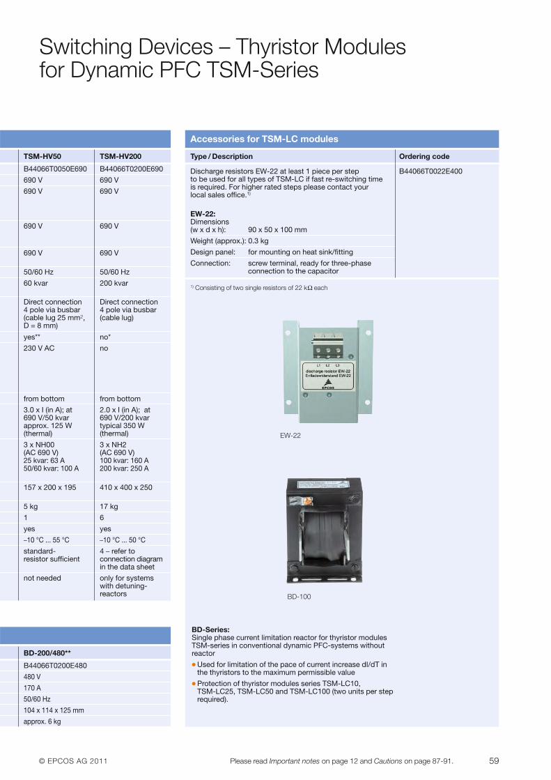
© EPCOS AG 2011 59Please read Important notes on page 12 and Cautions on page 87-91.
Switching Devices – Thyristor Modules for Dynamic PFC TSM-Series
TSM-HV50 TSM-HV200
B44066T0050E690 B44066T0200E690
690 V 690 V
690 V 690 V
690 V 690 V
690 V 690 V
50/60 Hz 50/60 Hz
60 kvar 200 kvar
yes** no*
230 V AC no
from bottom from bottom
3 x NH00 3 x NH2 (AC 690 V) (AC 690 V)25 kvar: 63 A 100 kvar: 160 A50/60 kvar: 100 A 200 kvar: 250 A
157 x 200 x 195 410 x 400 x 250
5 kg 17 kg
1 6
yes yes
–10 °C ... 55 °C –10 °C ... 50 °C
standard- 4 – refer toresistor sufficient connection diagram
in the data sheet
not needed only for systemswith detuning-reactors
Accessories for TSM-LC modules
Discharge resistors EW-22 at least 1 piece per step B44066T0022E400to be used for all types of TSM-LC if fast re-switching time is required. For higher rated steps please contact your local sales office.1)
EW-22:Dimensions(w x d x h): 90 x 50 x 100 mm
Weight (approx.): 0.3 kg
Design panel: for mounting on heat sink/fitting
Connection: screw terminal, ready for three-phaseconnection to the capacitor
1) Consisting of two single resistors of 22 kΩ each
EW-22
BD-100
Direct connection4 pole via busbar(cable lug 25 mm2,D = 8 mm)
Direct connection4 pole via busbar(cable lug)
3.0 x I (in A); at690 V/50 kvarapprox. 125 W (thermal)
2.0 x I (in A); at690 V/200 kvar typical 350 W (thermal)
Type / Description Ordering code
BD-200/480**
B44066T0200E480
480 V
170 A
50/60 Hz
104 x 114 x 125 mm
approx. 6 kg
BD-Series:Single phase current limitation reactor for thyristor modulesTSM-series in conventional dynamic PFC-systems withoutreactor� Used for limitation of the pace of current increase dI/dT in
the thyristors to the maximum permissible value� Protection of thyristor modules series TSM-LC10,
TSM-LC25, TSM-LC50 and TSM-LC100 (two units per steprequired).
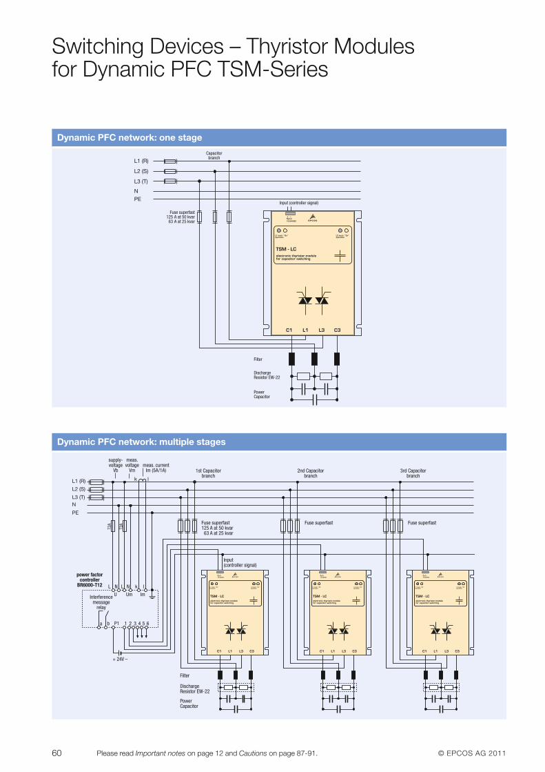
60 © EPCOS AG 2011Please read Important notes on page 12 and Cautions on page 87-91.
Switching Devices – Thyristor Modules for Dynamic PFC TSM-Series
Dynamic PFC network: one stage
Dynamic PFC network: multiple stages
1st Capacitorbranch
L1 (R)
L2 (S)
L3 (T)N
PE
Input(controller signal)
L
2nd Capacitorbranch
3rd Capacitorbranch
Fuse superfast125 A at 50 kvar 63 A at 25 kvar
Fuse superfast Fuse superfast
Filter
DischargeResistor EW-22
PowerCapacitor
N L N k l
U Um lmInterferencemessage
relay
a b P1 1 2 3 4 5 6
+ 24V –
T2A
T2A
power factorcontroller
BR6000-T12
supply-voltage
Vb
meas.voltage
Vmmeas. current
Im (5A/1A)
k l
Input (controller signal)
L1 (R)
L2 (S)
L3 (T)
NPE
Capacitorbranch
Fuse superfast125 A at 50 kvar63 A at 25 kvar
Filter
DischargeResistor EW-22
PowerCapacitor
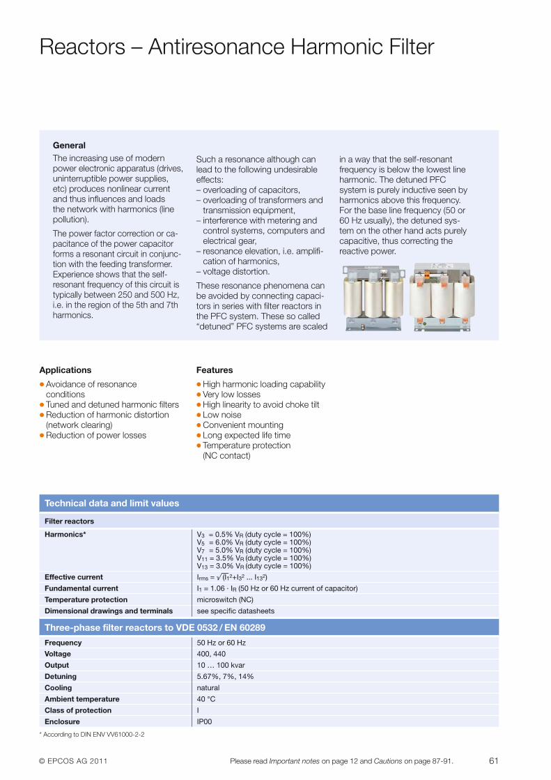
© EPCOS AG 2011 61Please read Important notes on page 12 and Cautions on page 87-91.
Reactors – Antiresonance Harmonic Filter
GeneralThe increasing use of modernpower electronic apparatus (drives,uninterruptible power supplies,etc) produces nonlinear currentand thus influences and loads the network with harmonics (linepollution).
The power factor correction or ca-pacitance of the power capacitorforms a resonant circuit in conjunc-tion with the feeding transformer.Experience shows that the self-resonant frequency of this circuit istypically between 250 and 500 Hz,i.e. in the region of the 5th and 7thharmonics.
Such a resonance although canlead to the following undesirableeffects:– overloading of capacitors,– overloading of transformers and
transmission equipment,– interference with metering and
control systems, computers andelectrical gear,
– resonance elevation, i.e. amplifi-cation of harmonics,
– voltage distortion.
These resonance phenomena canbe avoided by connecting capaci-tors in series with filter reactors inthe PFC system. These so called“detuned” PFC systems are scaled
in a way that the self-resonant frequency is below the lowest lineharmonic. The detuned PFC system is purely inductive seen byharmonics above this frequency.For the base line frequency (50 or60 Hz usually), the detuned sys-tem on the other hand acts purelycapacitive, thus correcting the reactive power.
Applications
� Avoidance of resonance conditions
� Tuned and detuned harmonic filters� Reduction of harmonic distortion
(network clearing)� Reduction of power losses
Features
� High harmonic loading capability� Very low losses� High linearity to avoid choke tilt� Low noise� Convenient mounting� Long expected life time� Temperature protection
(NC contact)
Technical data and limit values
Filter reactors
Harmonics* V3 = 0.5% VR (duty cycle = 100%)V5 = 6.0% VR (duty cycle = 100%)V7 = 5.0% VR (duty cycle = 100%)V11 = 3.5% VR (duty cycle = 100%)V13 = 3.0% VR (duty cycle = 100%)
Effective current Irms = ß®(I12+I32 ... I132)
Fundamental current I1 = 1.06 · IR (50 Hz or 60 Hz current of capacitor)
Temperature protection microswitch (NC)
Dimensional drawings and terminals see specific datasheets
Three-phase filter reactors to VDE 0532 / EN 60289
Frequency 50 Hz or 60 Hz
Voltage 400, 440
Output 10 … 100 kvar
Detuning 5.67%, 7%, 14%
Cooling natural
Ambient temperature 40 °C
Class of protection I
Enclosure IP00
* According to DIN ENV VV61000-2-2
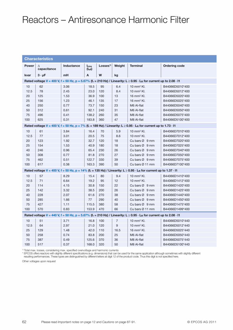
62 © EPCOS AG 2011Please read Important notes on page 12 and Cautions on page 87-91.
Reactors – Antiresonance Harmonic Filter
Characteristics
Power Δ Inductance Irms Losses1) Weight Terminal Ordering codecapacitance (Ieff)
kvar 3 · µF mH A W kg
Rated voltage V = 400 V, f = 50 Hz, p = 5.67% (fr = 210 Hz) / Linearity: L ≥ 0.95 · LR for current up to 2.08 · I1
10 62 3.06 18.5 95 6.4 10 mm2 Kl. B44066D5010*400
12.5 78 2.45 23.0 120 8.4 10 mm2 Kl. B44066D5012*400
20 125 1.53 36.9 100 13 16 mm2 Kl. B44066D5020*400
25 156 1.23 46.1 135 17 16 mm2 Kl. B44066D5025*400
40 250 0.77 73.7 150 23 M6 Al-flat B44066D5040*400
50 312 0.61 92.1 240 31 M6 Al-flat B44066D5050*400
75 496 0.41 138.2 260 35 M8 Al-flat B44066D5075*400
100 625 0.31 183.8 360 47 M8 Al-flat B44066D5100*400
Rated voltage V = 400 V, f = 50 Hz, p = 7% (fr = 189 Hz) / Linearity: L ≥ 0.95 · LR for current up to 1.73 · I1
10 61 3.84 16.4 70 5.9 10 mm2 Kl. B44066D7010*400
12.5 77 3.01 20.5 75 8.6 10 mm2 Kl. B44066D7012*400
20 123 1.92 32.7 120 18 Cu bars Ø 9 mm B44066D7020*400
25 154 1.53 40.9 180 18 Cu bars Ø 9 mm B44066D7025*400
40 246 0.96 65.4 230 26 Cu bars Ø 9 mm B44066D7040*400
50 308 0.77 81.8 270 27 Cu bars Ø 9 mm B44066D7050*400
75 462 0.51 122.7 330 39 Cu bars Ø 9 mm B44066D7075*400
100 617 0.38 163.3 390 50 Cu bars Ø 11 mm B44066D7100*400
Rated voltage V = 400 V, f = 50 Hz, p = 14% (fr = 135 Hz) / Linearity: L ≥ 0.95 · LR for current up to 1.37 · I1
10 57 8.29 15.4 80 9.4 10 mm2 Kl. B44066D1410*400
12.5 71 6.64 19.2 95 12 10 mm2 Kl. B44066D1412*400
20 114 4.15 30.8 150 22 Cu bars Ø 9 mm B44066D1420*400
25 142 3.32 38.5 200 26 Cu bars Ø 9 mm B44066D1425*400
40 228 2.07 61.6 270 38 Cu bars Ø 9 mm B44066D1440*400
50 285 1.66 77 290 40 Cu bars Ø 9 mm B44066D1450*400
75 427 1.11 115.5 380 58 Cu bars Ø 9 mm B44066D1475*400
100 570 0.83 153.9 470 66 Cu bars Ø 11 mm B44066D1499*400
Rated voltage V = 440 V, f = 50 Hz, p = 5.67% (fr = 210 Hz) / Linearity: L ≥ 0.95 · LR for current up to 2.08 · I1
10 51 3.71 16.8 100 7 10 mm2 Kl. B44066D5010*440
12.5 64 2.97 21.0 120 9 10 mm2 Kl. B44066D5012*440
25 129 1.48 42.0 110 16.5 16 mm2 Kl. B44066D5025*440
50 258 0.74 83.8 200 25 M6 Al-flat B44066D5050*440
75 387 0.49 125.6 370 36 M8 Al-flat B44066D5075*440
100 517 0.37 168.0 320 50 M8 Al-flat B44066D5100*440
1) Total max. losses, considering max. specified overvoltage and harmonic currents* EPCOS offers reactors with slightly different specifications (e.g. dimensions) that can be used for the same application although sometimes with slightly different
resulting performances. These types are distinguished by different letters at digit 12 of the product code. Thus this digit is not specified here.
Other voltages upon request
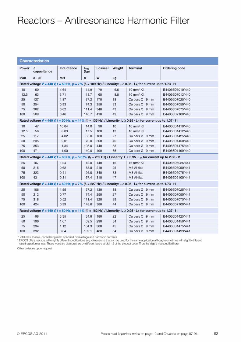
© EPCOS AG 2011 63Please read Important notes on page 12 and Cautions on page 87-91.
Reactors – Antiresonance Harmonic Filter
1) Total max. losses, considering max. specified overvoltage and harmonic currents* EPCOS offers reactors with slightly different specifications (e.g. dimensions) that can be used for the same application although sometimes with slightly different
resulting performances. These types are distinguished by different letters at digit 12 of the product code. Thus this digit is not specified here.
Other voltages upon request
Characteristics
Power Δ Inductance Irms Losses1) Weight Terminal Ordering codecapacitance (Ieff)
kvar 3 · µF mH A W kg
Rated voltage V = 440 V, f = 50 Hz, p = 7% (fr = 189 Hz) / Linearity: L ≥ 0.95 · LR for current up to 1.73 · I1
10 50 4.64 14.9 70 6.5 10 mm2 Kl. B44066D7010*440
12.5 63 3.71 18.7 65 8.5 10 mm2 Kl. B44066D7012*440
25 127 1.87 37.2 170 18 Cu bars Ø 9 mm B44066D7025*440
50 254 0.93 74.3 250 33 Cu bars Ø 9 mm B44066D7050*440
75 382 0.62 111.4 340 43 Cu bars Ø 9 mm B44066D7075*440
100 509 0.46 148.7 410 49 Cu bars Ø 9 mm B44066D7100*440
Rated voltage V = 440 V, f = 50 Hz, p = 14% (fr = 135 Hz) / Linearity: L ≥ 0.95 · LR for current up to 1.37 · I1
10 47 10.04 14.0 90 10 10 mm2 Kl. B44066D1410*440
12.5 58 8.03 17.5 100 13 10 mm2 Kl. B44066D1412*440
25 117 4.02 35.0 160 27 Cu bars Ø 9 mm B44066D1425*440
50 235 2.01 70.0 300 40 Cu bars Ø 9 mm B44066D1450*440
75 353 1.34 105.0 440 53 Cu bars Ø 9 mm B44066D1475*440
100 471 1.00 140.0 490 65 Cu bars Ø 9 mm B44066D1499*440
Rated voltage V = 440 V, f = 60 Hz, p = 5.67% (fr = 252 Hz) / Linearity: L ≥ 0.95 · LR for current up to 2.08 · I1
25 107 1.24 42.0 140 16 16 mm2 Kl. B44066D5025*441
50 215 0.62 83.8 210 25 M6 Al-flat B44066D5050*441
75 323 0.41 126.0 340 33 M8 Al-flat B44066D5075*441
100 431 0.31 167.4 310 47 M8 Al-flat B44066D5100*441
Rated voltage V = 440 V, f = 60 Hz, p = 7% (fr = 227 Hz) / Linearity: L ≥ 0.95 · LR for current up to 1.73 · I1
25 106 1.55 37.2 130 18 Cu bars Ø 9 mm B44066D7025*441
50 212 0.77 74.4 250 27 Cu bars Ø 9 mm B44066D7050*441
75 318 0.52 111.4 320 39 Cu bars Ø 9 mm B44066D7075*441
100 424 0.39 148.6 380 44 Cu bars Ø 9 mm B44066D7100*441
Rated voltage V = 440 V, f = 60 Hz, p = 14% (fr = 162 Hz) / Linearity: L ≥ 0.95 · LR for current up to 1.37 · I1
25 98 3.35 34.8 180 22 Cu bars Ø 9 mm B44066D1425*441
50 196 1.67 69.5 290 34 Cu bars Ø 9 mm B44066D1450*441
75 294 1.12 104.3 380 45 Cu bars Ø 9 mm B44066D1475*441
100 392 0.84 139.1 480 54 Cu bars Ø 9 mm B44066D1499*441
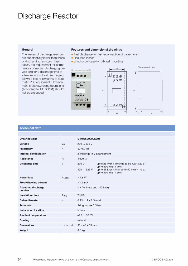
64 © EPCOS AG 2011Please read Important notes on page 12 and Cautions on page 87-91.
Discharge Reactor
General
The losses of discharge reactors are substantially lower than thoseof discharging resistors. They satisfy the requirement for perma-nently connected discharging de-vice and for a discharge time of a few seconds. Fast dischargingallows a fast re-switching in auto-matic PFC equipment. However,max. 5 000 switching operations(according to IEC 60831) shouldnot be exceeded.
Features and dimensional drawings
� Fast discharge for fast reconnection of capacitors� Reduced losses� Shockproof case for DIN rail mounting
U V W
72.5
45
34
90
545
Dimensions in mm
Technical data
Ordering code B44066E9900S001
Voltage VR 230 ... 525 V
Frequency f 50 / 60 Hz
Internal configuration 2 windings in V arrangement
Resistance R 4 900 Ω
Discharge time t 230 V up to 25 kvar < 10 s / up to 50 kvar < 20 s /up to 100 kvar < 40 s
400 … 525 V up to 25 kvar < 5 s / up to 50 kvar < 10 s / up to 100 kvar < 20 s
Power loss PLOSS < 1.8 W
Free-wheeling current I < 4.5 mA
Accepted discharge 1 x / (minute and 100 kvar)number
Insulation class RINS T40/B
Cable diameter ø 0.75 … 2 x 2.5 mm2
Terminals fixing torque 0.5 Nm
Installation location indoor
Ambient temperature –25 … 55 °C
Cooling natural
Dimensions h x w x d 90 x 45 x 59 mm
Weight 0.5 kg
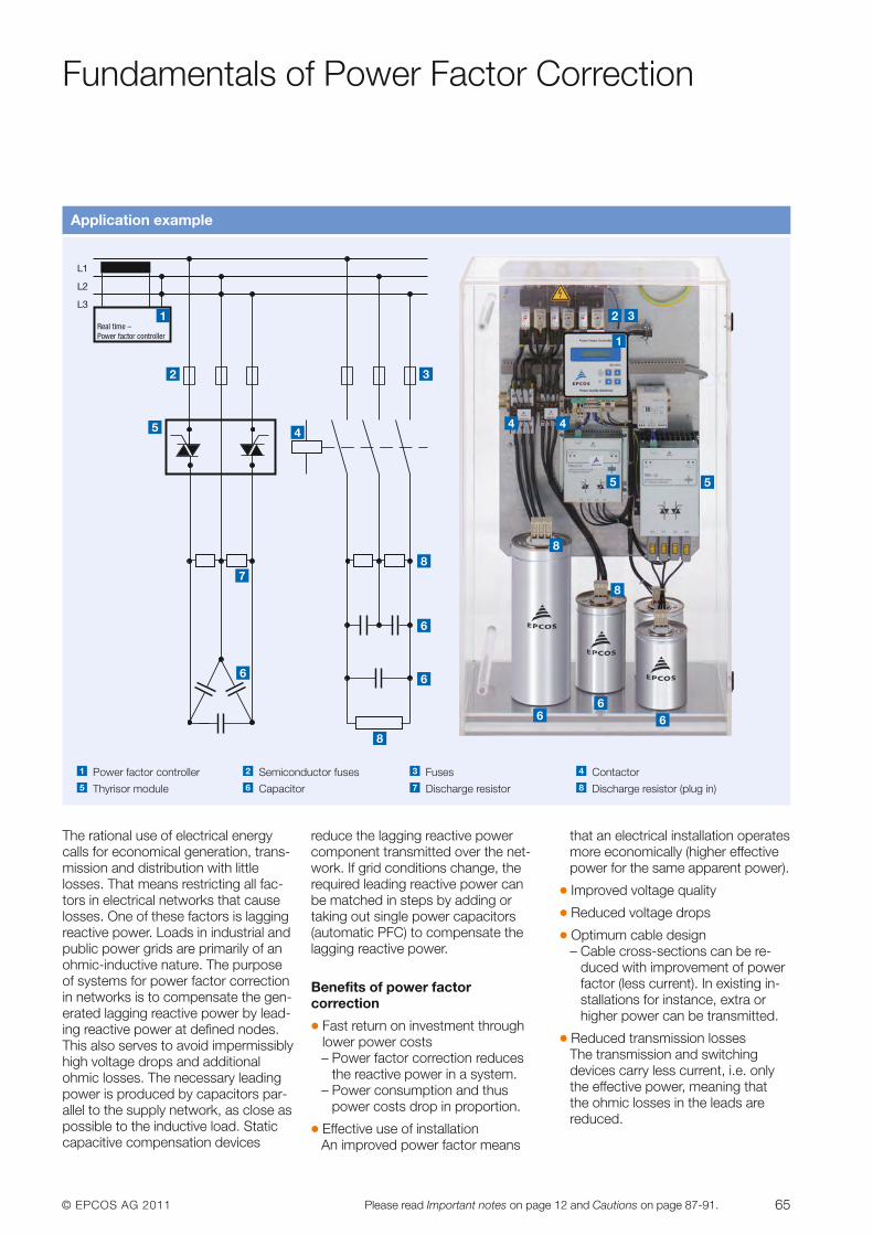
© EPCOS AG 2011 65Please read Important notes on page 12 and Cautions on page 87-91.
Fundamentals of Power Factor Correction
Application example
L1
L2
L3
Real time –Power factor controller
1
2
6
7
3
45
1
2 3
8
6
6
5 5
8
6 66
8
Power factor controller Semiconductor fuses Fuses Contactor
Thyrisor module Capacitor Discharge resistor Discharge resistor (plug in)
3 4
8765
21
The rational use of electrical energycalls for economical generation, trans-mission and distribution with little losses. That means restricting all fac-tors in electrical networks that causelosses. One of these factors is laggingreactive power. Loads in industrial andpublic power grids are primarily of anohmic-inductive nature. The purposeof systems for power factor correctionin networks is to compensate the gen-erated lagging reactive power by lead-ing reactive power at defined nodes.This also serves to avoid impermissiblyhigh voltage drops and additionalohmic losses. The necessary leadingpower is produced by capacitors par-allel to the supply network, as close aspossible to the inductive load. Staticcapacitive compensation devices
reduce the lagging reactive powercomponent transmitted over the net-work. If grid conditions change, the required leading reactive power canbe matched in steps by adding or taking out single power capacitors(automatic PFC) to compensate thelagging reactive power.
Benefits of power factor correction
� Fast return on investment throughlower power costs – Power factor correction reduces
the reactive power in a system. – Power consumption and thus
power costs drop in proportion.
� Effective use of installation An improved power factor means
that an electrical installation operatesmore economically (higher effectivepower for the same apparent power).
� Improved voltage quality
� Reduced voltage drops
� Optimum cable design– Cable cross-sections can be re-
duced with improvement of powerfactor (less current). In existing in-stallations for instance, extra orhigher power can be transmitted.
� Reduced transmission losses The transmission and switching devices carry less current, i.e. onlythe effective power, meaning that the ohmic losses in the leads are reduced.
8
4 4
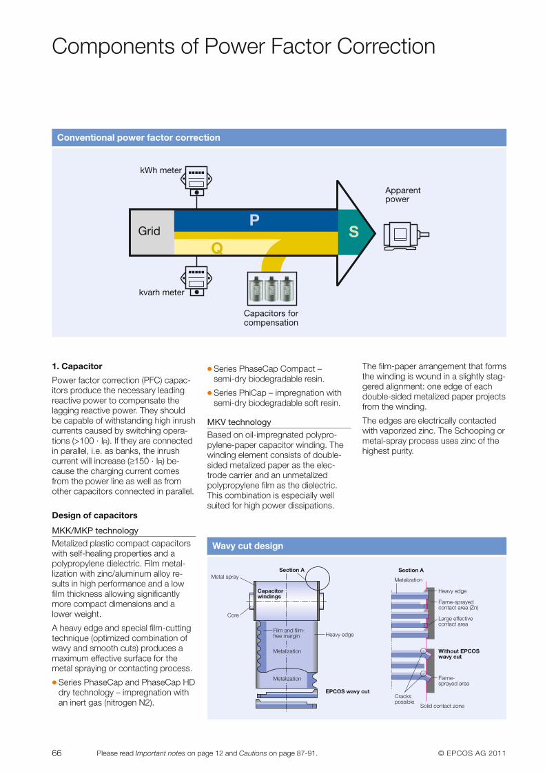
66 © EPCOS AG 2011Please read Important notes on page 12 and Cautions on page 87-91.
Components of Power Factor Correction
1. Capacitor
Power factor correction (PFC) capac -itors produce the necessary leadingreactive power to compensate the lagging reactive power. They shouldbe capable of withstanding high inrushcurrents caused by switching opera-tions (>100 · IR). If they are connectedin parallel, i.e. as banks, the inrushcurrent will increase (≥150 · IR) be-cause the charging current comesfrom the power line as well as fromother capacitors connected in parallel.
Design of capacitors
MKK/MKP technologyMetalized plastic compact capacitorswith self-healing properties and apolypropylene dielectric. Film metal-lization with zinc/aluminum alloy re-sults in high performance and a lowfilm thickness allowing significantlymore compact dimensions and a lower weight.
A heavy edge and special film-cuttingtechnique (optimized combination ofwavy and smooth cuts) produces amaximum effective surface for themetal spraying or contacting process.
� Series PhaseCap and PhaseCap HDdry technology – impregnation with an inert gas (nitrogen N2).
� Series PhaseCap Compact –semi-dry biodegradable resin.
� Series PhiCap – impregnation with semi-dry biodegradable soft resin.
MKV technologyBased on oil-impregnated polypro-pylene-paper capacitor winding. Thewinding element consists of double-sided metalized paper as the elec-trode carrier and an unmetalizedpolypropylene film as the dielectric.This combination is especially wellsuited for high power dissipations.
The film-paper arrangement that formsthe winding is wound in a slightly stag-gered alignment: one edge of eachdouble-sided metalized paper projectsfrom the winding.
The edges are electrically contactedwith vaporized zinc. The Schooping ormetal-spray process uses zinc of thehighest purity.
Wavy cut design
kWh meter
Apparentpower
Capacitors forcompensation
kvarh meter
GridP
SQ
Conventional power factor correction
Section A
Capacitorwindings
Metal spray
Core
Film and film-free margin
Metalization
Metalization
Heavy edge
EPCOS wavy cut
Section A
Without EPCOSwavy cut
Solid contact zone
Crackspossible
Flame-sprayed area
Heavy edge
Flame-sprayedcontact area (Zn)
Large effectivecontact area
Metalization
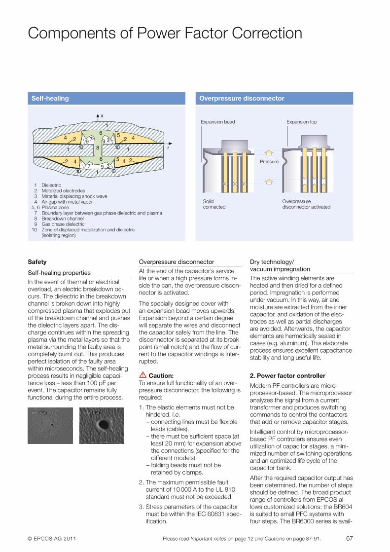
© EPCOS AG 2011 67Please read Important notes on page 12 and Cautions on page 87-91.
Components of Power Factor Correction
Safety
Self-healing propertiesIn the event of thermal or electricaloverload, an electric breakdown oc-curs. The dielectric in the breakdownchannel is broken down into highlycompressed plasma that explodes outof the breakdown channel and pushesthe dielectric layers apart. The dis-charge continues within the spreadingplasma via the metal layers so that themetal surrounding the faulty area iscompletely burnt out. This producesperfect isolation of the faulty area within microseconds. The self-healingprocess results in negligible capaci-tance loss – less than 100 pF perevent. The capacitor remains fullyfunctional during the entire process.
Overpressure disconnectorAt the end of the capacitor’s servicelife or when a high pressure forms in-side the can, the overpressure discon-nector is activated.
The specially designed cover with an expansion bead moves upwards.Expansion beyond a certain degreewill separate the wires and disconnectthe capacitor safely from the line. Thedisconnector is separated at its breakpoint (small notch) and the flow of cur-rent to the capacitor windings is inter-rupted.
V Caution: To ensure full functionality of an over-pressure disconnector, the following isrequired:
1. The elastic elements must not behindered, i.e.– connecting lines must be flexible
leads (cables),– there must be sufficient space (at
least 20 mm) for expansion abovethe connections (specified for thedifferent models),
– folding beads must not be retained by clamps.
2. The maximum permissible fault current of 10 000 A to the UL 810standard must not be exceeded.
3. Stress parameters of the capacitormust be within the IEC 60831 spec-ification.
Dry technology/vacuum impregnationThe active winding elements are heated and then dried for a defined period. Impregnation is performed under vacuum. In this way, air andmoisture are extracted from the innercapacitor, and oxidation of the elec-trodes as well as partial discharges are avoided. Afterwards, the capacitorelements are hermetically sealed incases (e.g. aluminum). This elaborateprocess ensures excellent capacitancestability and long useful life.
2. Power factor controller
Modern PF controllers are micro-processor-based. The microprocessoranalyzes the signal from a currenttransformer and produces switchingcommands to control the contactorsthat add or remove capacitor stages.
Intelligent control by microprocessor-based PF controllers ensures even utilization of capacitor stages, a mini-mized number of switching operationsand an optimized life cycle of the capacitor bank.
After the required capacitor output hasbeen determined, the number of stepsshould be defined. The broad productrange of controllers from EPCOS al-lows customized solutions: the BR604is suited to small PFC systems withfour steps. The BR6000 series is avail-
Self-healing
x
r1 10
4 2
42
6
6
8 10 1
2 4
245
5
10 101
1
399 7
37 9
1 Dielectric2 Metalized electrodes3 Material displacing shock wave4 Air gap with metal vapor
5, 6 Plasma zone7 Boundary layer between gas phase dielectric and plasma8 Breakdown channel9 Gas phase dielectric
10 Zone of displaced metalization and dielectric (isolating region)
Overpressure disconnector
Solid connected
Overpressure disconnector activated
Pressure
Expansion topExpansion bead
30 µm 10 µm
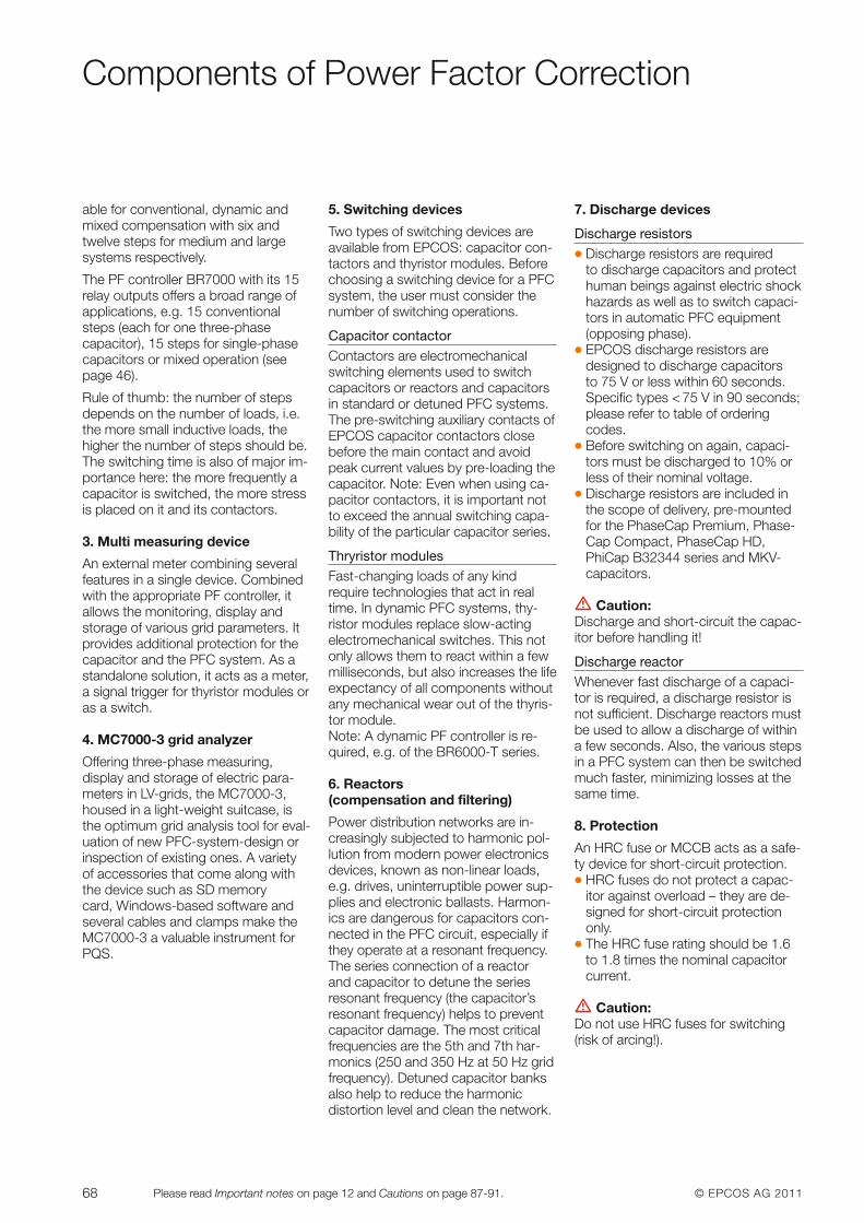
68 © EPCOS AG 2011Please read Important notes on page 12 and Cautions on page 87-91.
Components of Power Factor Correction
able for conventional, dynamic andmixed compensation with six andtwelve steps for medium and largesystems respectively.
The PF controller BR7000 with its 15relay outputs offers a broad range ofapplications, e.g. 15 conventionalsteps (each for one three-phase capa citor), 15 steps for single-phasecapacitors or mixed operation (seepage 46).
Rule of thumb: the number of stepsdepends on the number of loads, i.e.the more small inductive loads, thehigher the number of steps should be.The switching time is also of major im-portance here: the more frequently acapacitor is switched, the more stressis placed on it and its contactors.
3. Multi measuring device
An external meter combining severalfeatures in a single device. Combinedwith the appropriate PF controller, it allows the monitoring, display andstorage of various grid parameters. Itprovides additional protection for thecapacitor and the PFC system. As astandalone solution, it acts as a meter,a signal trigger for thyristor modules oras a switch.
4. MC7000-3 grid analyzer
Offering three-phase measuring, display and storage of electric para-meters in LV-grids, the MC7000-3,housed in a light-weight suitcase, isthe optimum grid analysis tool for eval-uation of new PFC-system-design orinspection of existing ones. A varietyof accessories that come along withthe device such as SD memory card, Windows-based software andseveral cables and clamps make theMC7000-3 a valuable instrument forPQS.
5. Switching devices
Two types of switching devices areavailable from EPCOS: capacitor con-tactors and thyristor modules. Beforechoosing a switching device for a PFCsystem, the user must consider thenumber of switching operations.
Capacitor contactorContactors are electromechanicalswitching elements used to switch capacitors or reactors and capacitorsin standard or detuned PFC systems.The pre-switching auxiliary contacts of EPCOS capacitor contactors closebefore the main contact and avoidpeak current values by pre-loading thecapacitor. Note: Even when using ca-pacitor contactors, it is important notto exceed the annual switching capa-bility of the particular capacitor series.
Thryristor modules Fast-changing loads of any kind require technologies that act in realtime. In dynamic PFC systems, thy -ristor modules replace slow-actingelectromechanical switches. This notonly allows them to react within a fewmilliseconds, but also increases the lifeexpectancy of all components withoutany mechanical wear out of the thyris-tor module.Note: A dynamic PF controller is re-quired, e.g. of the BR6000-T series.
6. Reactors (compensation and filtering)
Power distribution networks are in-creasingly subjected to harmonic pol-lution from modern power electronicsdevices, known as non -linear loads,e.g. drives, uninter ruptible power sup-plies and electronic ballasts. Harmon-ics are dangerous for capacitors con-nected in the PFC circuit, especially ifthey operate at a resonant frequency.The series connection of a reactor and capac itor to detune the seriesresonant frequency (the capacitor’sresonant frequency) helps to preventca pacitor damage. The most criticalfrequencies are the 5th and 7th har-monics (250 and 350 Hz at 50 Hz gridfrequency). Detuned capacitor banks also help to reduce the harmonic distortion level and clean the network.
7. Discharge devices
Discharge resistors� Discharge resistors are required
to discharge capacitors and protecthuman beings against electric shockhazards as well as to switch capaci-tors in automatic PFC equipment(opposing phase).
� EPCOS discharge resistors are designed to discharge capacitors to 75 V or less within 60 seconds.Specific types < 75 V in 90 seconds;please refer to table of orderingcodes.
� Before switching on again, capaci-tors must be discharged to 10% orless of their nominal voltage.
� Discharge resistors are included inthe scope of delivery, pre-mountedfor the PhaseCap Premium, Phase-Cap Compact, PhaseCap HD,PhiCap B32344 series and MKV-capa citors.
V Caution: Discharge and short-circuit the capac-itor before handling it!
Discharge reactorWhenever fast discharge of a capaci-tor is required, a discharge resistor isnot sufficient. Discharge reactors mustbe used to allow a discharge of withina few seconds. Also, the various stepsin a PFC system can then be switchedmuch faster, minimizing losses at thesame time.
8. Protection
An HRC fuse or MCCB acts as a safe-ty device for short-circuit protection.� HRC fuses do not protect a ca pac -
itor against overload – they are de-signed for short-circuit protectiononly.
� The HRC fuse rating should be 1.6to 1.8 times the nominal capacitorcurrent.
V Caution: Do not use HRC fuses for switching(risk of arcing!).
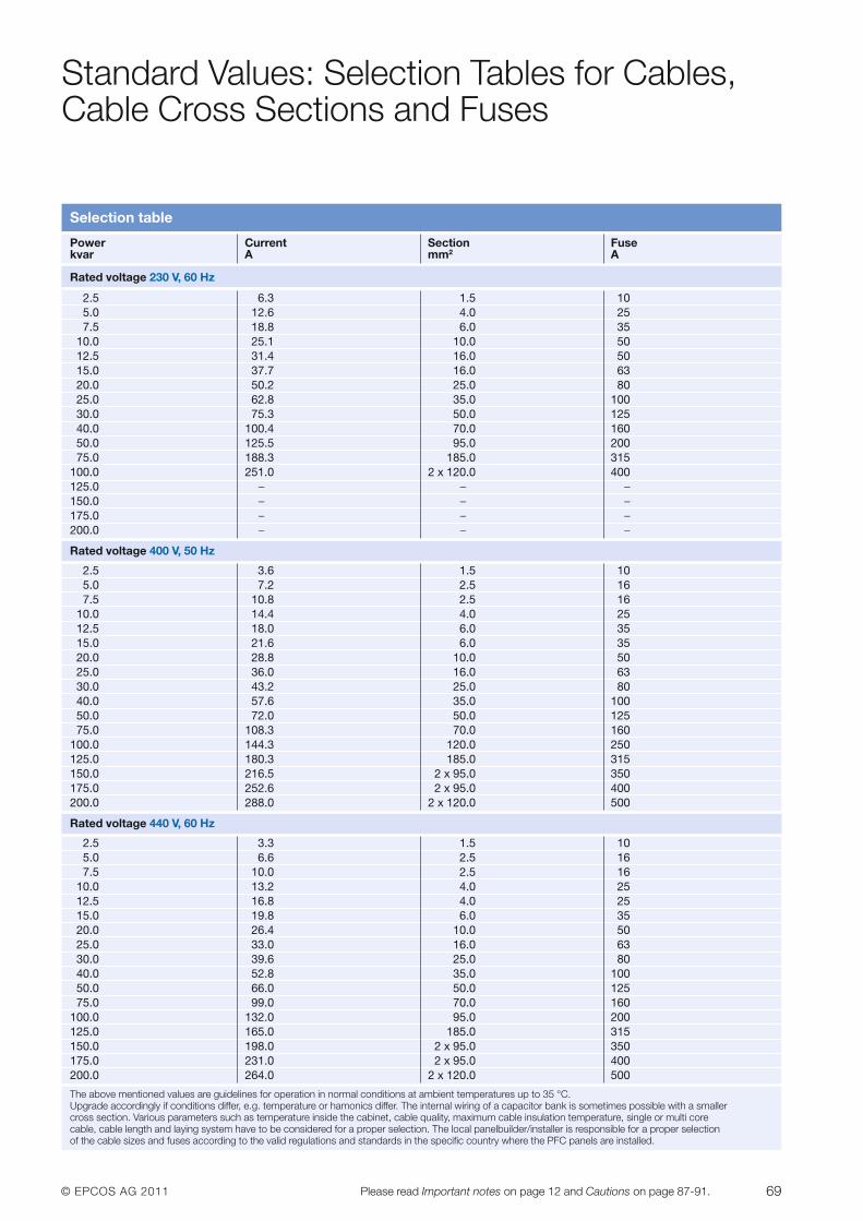
© EPCOS AG 2011 69Please read Important notes on page 12 and Cautions on page 87-91.
Standard Values: Selection Tables for Cables,Cable Cross Sections and Fuses
Selection table
Power Current Section Fusekvar A mm2 A
Rated voltage 230 V, 60 Hz
2.5 6.3 1.5 105.0 12.6 4.0 257.5 18.8 6.0 35
10.0 25.1 10.0 5012.5 31.4 16.0 5015.0 37.7 16.0 6320.0 50.2 25.0 8025.0 62.8 35.0 10030.0 75.3 50.0 12540.0 100.4 70.0 16050.0 125.5 95.0 20075.0 188.3 185.0 315
100.0 251.0 2 x 120.0 400125.0 – – –150.0 – – –175.0 – – –200.0 – – –
Rated voltage 400 V, 50 Hz
2.5 3.6 1.5 105.0 7.2 2.5 167.5 10.8 2.5 16
10.0 14.4 4.0 2512.5 18.0 6.0 3515.0 21.6 6.0 3520.0 28.8 10.0 5025.0 36.0 16.0 6330.0 43.2 25.0 8040.0 57.6 35.0 10050.0 72.0 50.0 12575.0 108.3 70.0 160
100.0 144.3 120.0 250125.0 180.3 185.0 315150.0 216.5 2 x 95.0 350175.0 252.6 2 x 95.0 400200.0 288.0 2 x 120.0 500
Rated voltage 440 V, 60 Hz
2.5 3.3 1.5 105.0 6.6 2.5 167.5 10.0 2.5 16
10.0 13.2 4.0 2512.5 16.8 4.0 2515.0 19.8 6.0 3520.0 26.4 10.0 5025.0 33.0 16.0 6330.0 39.6 25.0 8040.0 52.8 35.0 10050.0 66.0 50.0 12575.0 99.0 70.0 160
100.0 132.0 95.0 200125.0 165.0 185.0 315150.0 198.0 2 x 95.0 350175.0 231.0 2 x 95.0 400200.0 264.0 2 x 120.0 500
The above mentioned values are guidelines for operation in normal conditions at ambient temperatures up to 35 °C.Upgrade accordingly if conditions differ, e.g. temperature or hamonics differ. The internal wiring of a capacitor bank is sometimes possible with a smallercross section. Various parameters such as temperature inside the cabinet, cable quality, maximum cable insulation temperature, single or multi corecable, cable length and laying system have to be considered for a proper selection. The local panelbuilder/installer is responsible for a proper selectionof the cable sizes and fuses according to the valid regulations and standards in the specific country where the PFC panels are installed.
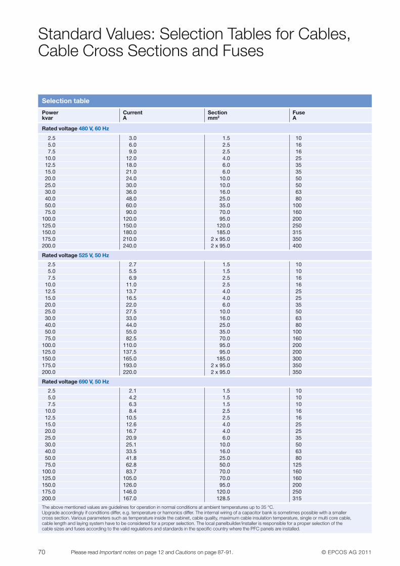
70 © EPCOS AG 2011Please read Important notes on page 12 and Cautions on page 87-91.
Standard Values: Selection Tables for Cables,Cable Cross Sections and Fuses
Selection table
Power Current Section Fusekvar A mm2 A
The above mentioned values are guidelines for operation in normal conditions at ambient temperatures up to 35 °C.Upgrade accordingly if conditions differ, e.g. temperature or hamonics differ. The internal wiring of a capacitor bank is sometimes possible with a smallercross section. Various parameters such as temperature inside the cabinet, cable quality, maximum cable insulation temperature, single or multi core cable,cable length and laying system have to be considered for a proper selection. The local panelbuilder/installer is responsible for a proper selection of thecable sizes and fuses according to the valid regulations and standards in the specific country where the PFC panels are installed.
Rated voltage 480 V, 60 Hz
2.5 3.0 1.5 105.0 6.0 2.5 167.5 9.0 2.5 16
10.0 12.0 4.0 2512.5 18.0 6.0 3515.0 21.0 6.0 3520.0 24.0 10.0 5025.0 30.0 10.0 5030.0 36.0 16.0 6340.0 48.0 25.0 8050.0 60.0 35.0 10075.0 90.0 70.0 160
100.0 120.0 95.0 200125.0 150.0 120.0 250150.0 180.0 185.0 315175.0 210.0 2 x 95.0 350200.0 240.0 2 x 95.0 400
Rated voltage 525 V, 50 Hz
2.5 2.7 1.5 105.0 5.5 1.5 107.5 6.9 2.5 16
10.0 11.0 2.5 1612.5 13.7 4.0 2515.0 16.5 4.0 2520.0 22.0 6.0 3525.0 27.5 10.0 5030.0 33.0 16.0 6340.0 44.0 25.0 8050.0 55.0 35.0 10075.0 82.5 70.0 160
100.0 110.0 95.0 200125.0 137.5 95.0 200150.0 165.0 185.0 300175.0 193.0 2 x 95.0 350200.0 220.0 2 x 95.0 350
Rated voltage 690 V, 50 Hz
2.5 2.1 1.5 105.0 4.2 1.5 107.5 6.3 1.5 10
10.0 8.4 2.5 1612.5 10.5 2.5 1615.0 12.6 4.0 2520.0 16.7 4.0 2525.0 20.9 6.0 3530.0 25.1 10.0 5040.0 33.5 16.0 6350.0 41.8 25.0 8075.0 62.8 50.0 125
100.0 83.7 70.0 160125.0 105.0 70.0 160150.0 126.0 95.0 200175.0 146.0 120.0 250200.0 167.0 128.5 315
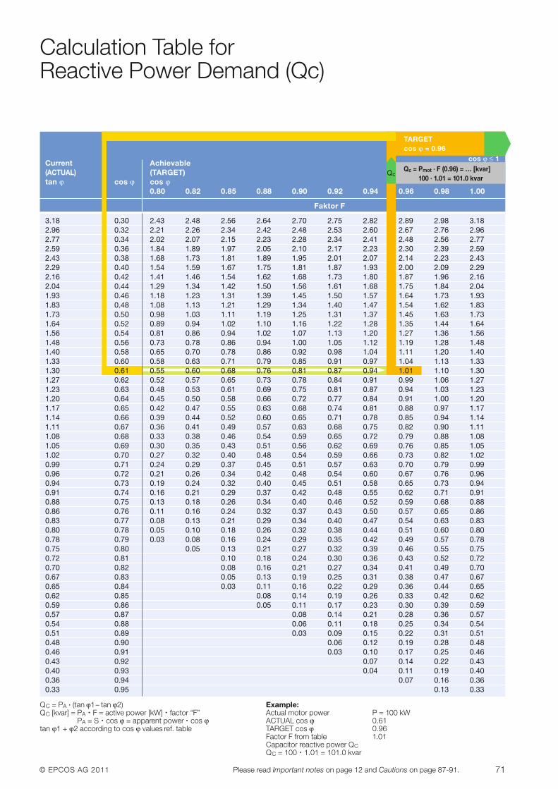
© EPCOS AG 2011 71Please read Important notes on page 12 and Cautions on page 87-91.
Calculation Table for Reactive Power Demand (Qc)
QC = PA · (tan ϕ1– tan ϕ2)QC [kvar] = PA · F = active power [kW] · factor “F”
PA = S · cos ϕ = apparent power · cos ϕtan ϕ1 + ϕ2 according to cos ϕ values ref. table
Example:Actual motor power P = 100 kWACTUAL cos ϕ 0.61TARGET cos ϕ 0.96Factor F from table 1.01Capacitor reactive power QCQC = 100 · 1.01 = 101.0 kvar
TARGET cos ϕ = 0.96
cos ϕ ≤ 1Qc = Pmot · F (0.96) = … [kvar]
100 · 1.01 = 101.0 kvar
Current Achievable (ACTUAL) (TARGET)tan ϕ cos ϕ cos ϕ
0.80 0.82 0.85 0.88 0.90 0.92 0.94 0.96 0.98 1.00
Faktor F
3.18 0.30 2.43 2.48 2.56 2.64 2.70 2.75 2.82 2.89 2.98 3.182.96 0.32 2.21 2.26 2.34 2.42 2.48 2.53 2.60 2.67 2.76 2.962.77 0.34 2.02 2.07 2.15 2.23 2.28 2.34 2.41 2.48 2.56 2.772.59 0.36 1.84 1.89 1.97 2.05 2.10 2.17 2.23 2.30 2.39 2.592.43 0.38 1.68 1.73 1.81 1.89 1.95 2.01 2.07 2.14 2.23 2.432.29 0.40 1.54 1.59 1.67 1.75 1.81 1.87 1.93 2.00 2.09 2.292.16 0.42 1.41 1.46 1.54 1.62 1.68 1.73 1.80 1.87 1.96 2.162.04 0.44 1.29 1.34 1.42 1.50 1.56 1.61 1.68 1.75 1.84 2.041.93 0.46 1.18 1.23 1.31 1.39 1.45 1.50 1.57 1.64 1.73 1.931.83 0.48 1.08 1.13 1.21 1.29 1.34 1.40 1.47 1.54 1.62 1.831.73 0.50 0.98 1.03 1.11 1.19 1.25 1.31 1.37 1.45 1.63 1.731.64 0.52 0.89 0.94 1.02 1.10 1.16 1.22 1.28 1.35 1.44 1.641.56 0.54 0.81 0.86 0.94 1.02 1.07 1.13 1.20 1.27 1.36 1.561.48 0.56 0.73 0.78 0.86 0.94 1.00 1.05 1.12 1.19 1.28 1.481.40 0.58 0.65 0.70 0.78 0.86 0.92 0.98 1.04 1.11 1.20 1.401.33 0.60 0.58 0.63 0.71 0.79 0.85 0.91 0.97 1.04 1.13 1.331.30 0.61 0.55 0.60 0.68 0.76 0.81 0.87 0.94 1.01 1.10 1.301.27 0.62 0.52 0.57 0.65 0.73 0.78 0.84 0.91 0.99 1.06 1.271.23 0.63 0.48 0.53 0.61 0.69 0.75 0.81 0.87 0.94 1.03 1.231.20 0.64 0.45 0.50 0.58 0.66 0.72 0.77 0.84 0.91 1.00 1.201.17 0.65 0.42 0.47 0.55 0.63 0.68 0.74 0.81 0.88 0.97 1.171.14 0.66 0.39 0.44 0.52 0.60 0.65 0.71 0.78 0.85 0.94 1.141.11 0.67 0.36 0.41 0.49 0.57 0.63 0.68 0.75 0.82 0.90 1.111.08 0.68 0.33 0.38 0.46 0.54 0.59 0.65 0.72 0.79 0.88 1.081.05 0.69 0.30 0.35 0.43 0.51 0.56 0.62 0.69 0.76 0.85 1.051.02 0.70 0.27 0.32 0.40 0.48 0.54 0.59 0.66 0.73 0.82 1.020.99 0.71 0.24 0.29 0.37 0.45 0.51 0.57 0.63 0.70 0.79 0.990.96 0.72 0.21 0.26 0.34 0.42 0.48 0.54 0.60 0.67 0.76 0.960.94 0.73 0.19 0.24 0.32 0.40 0.45 0.51 0.58 0.65 0.73 0.940.91 0.74 0.16 0.21 0.29 0.37 0.42 0.48 0.55 0.62 0.71 0.910.88 0.75 0.13 0.18 0.26 0.34 0.40 0.46 0.52 0.59 0.68 0.880.86 0.76 0.11 0.16 0.24 0.32 0.37 0.43 0.50 0.57 0.65 0.860.83 0.77 0.08 0.13 0.21 0.29 0.34 0.40 0.47 0.54 0.63 0.830.80 0.78 0.05 0.10 0.18 0.26 0.32 0.38 0.44 0.51 0.60 0.800.78 0.79 0.03 0.08 0.16 0.24 0.29 0.35 0.42 0.49 0.57 0.780.75 0.80 0.05 0.13 0.21 0.27 0.32 0.39 0.46 0.55 0.750.72 0.81 0.10 0.18 0.24 0.30 0.36 0.43 0.52 0.720.70 0.82 0.08 0.16 0.21 0.27 0.34 0.41 0.49 0.700.67 0.83 0.05 0.13 0.19 0.25 0.31 0.38 0.47 0.670.65 0.84 0.03 0.11 0.16 0.22 0.29 0.36 0.44 0.650.62 0.85 0.08 0.14 0.19 0.26 0.33 0.42 0.620.59 0.86 0.05 0.11 0.17 0.23 0.30 0.39 0.590.57 0.87 0.08 0.14 0.21 0.28 0.36 0.570.54 0.88 0.06 0.11 0.18 0.25 0.34 0.540.51 0.89 0.03 0.09 0.15 0.22 0.31 0.510.48 0.90 0.06 0.12 0.19 0.28 0.480.46 0.91 0.03 0.10 0.17 0.25 0.460.43 0.92 0.07 0.14 0.22 0.430.40 0.93 0.04 0.11 0.19 0.400.36 0.94 0.07 0.16 0.360.33 0.95 0.13 0.33
Qc
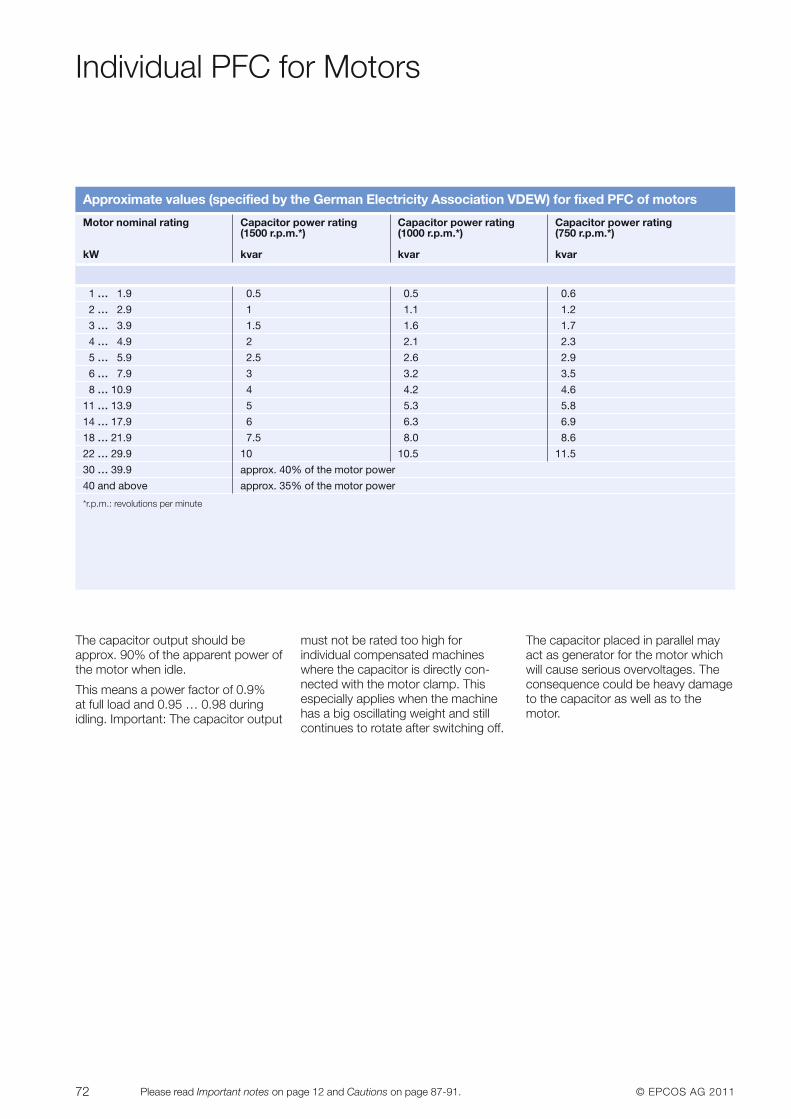
72 © EPCOS AG 2011Please read Important notes on page 12 and Cautions on page 87-91.
Individual PFC for Motors
Q
The capacitor output should be approx. 90% of the apparent power ofthe motor when idle.
This means a power factor of 0.9% at full load and 0.95 … 0.98 duringidling. Important: The capacitor output
must not be rated too high for individual compensated machineswhere the capacitor is directly con-nected with the motor clamp. This especially applies when the machinehas a big oscillating weight and stillcontinues to rotate after switching off.
The capacitor placed in parallel mayact as generator for the motor whichwill cause serious overvoltages. Theconsequence could be heavy damageto the capacitor as well as to the motor.
Approximate values (specified by the German Electricity Association VDEW) for fixed PFC of motors
Motor nominal rating Capacitor power rating Capacitor power rating Capacitor power rating(1500 r.p.m.*) (1000 r.p.m.*) (750 r.p.m.*)
kW kvar kvar kvar
1 … 1.9 0.5 0.5 0.6
2 … 2.9 1 1.1 1.2
3 … 3.9 1.5 1.6 1.7
4 … 4.9 2 2.1 2.3
5 … 5.9 2.5 2.6 2.9
6 … 7.9 3 3.2 3.5
8 … 10.9 4 4.2 4.6
11 … 13.9 5 5.3 5.8
14 … 17.9 6 6.3 6.9
18 … 21.9 7.5 8.0 8.6
22 … 29.9 10 10.5 11.5
30 … 39.9 approx. 40% of the motor power
40 and above approx. 35% of the motor power
*r.p.m.: revolutions per minute
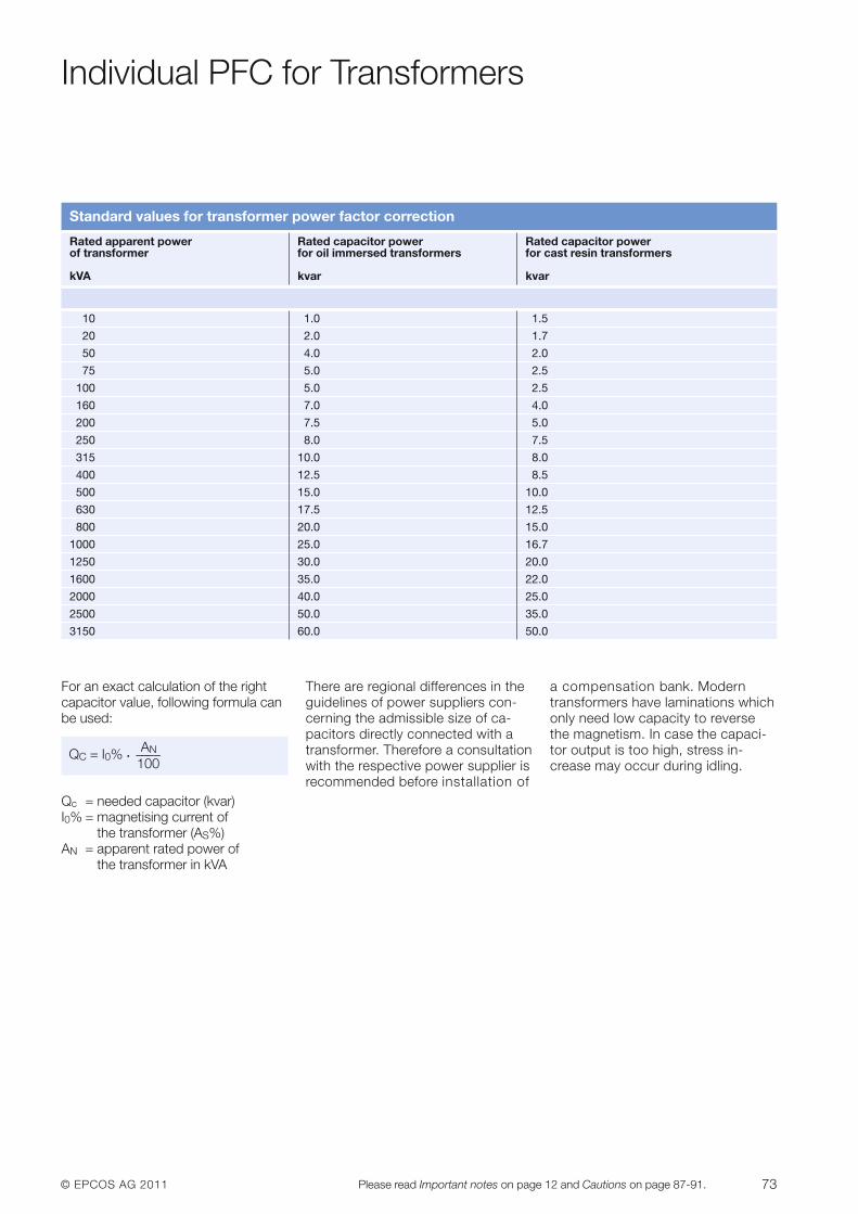
© EPCOS AG 2011 73Please read Important notes on page 12 and Cautions on page 87-91.
Individual PFC for Transformers
For an exact calculation of the rightcapacitor value, following formula canbe used:
ANQC = I0% · ––––100
Qc = needed capacitor (kvar)I0% = magnetising current of
the transformer (AS%)AN = apparent rated power of
the transformer in kVA
There are regional differences in theguidelines of power suppliers con-cerning the admissible size of ca-pacitors directly connected with atransformer. Therefore a consultationwith the respective power supplier isrecommended before installation of
a compensation bank. Moderntransformers have laminations whichonly need low capacity to reversethe magnetism. In case the capaci-tor output is too high, stress in-crease may occur during idling.
Standard values for transformer power factor correction
Rated apparent power Rated capacitor power Rated capacitor power of transformer for oil immersed transformers for cast resin transformers
kVA kvar kvar
10 1.0 1.5
20 2.0 1.7
50 4.0 2.0
75 5.0 2.5
100 5.0 2.5
160 7.0 4.0
200 7.5 5.0
250 8.0 7.5
315 10.0 8.0
400 12.5 8.5
500 15.0 10.0
630 17.5 12.5
800 20.0 15.0
1000 25.0 16.7
1250 30.0 20.0
1600 35.0 22.0
2000 40.0 25.0
2500 50.0 35.0
3150 60.0 50.0
74 © EPCOS AG 2011Please read Important notes on page 12 and Cautions on page 87-91.
Detuned PFC in General
When installing capacitors for PFCpurpose, the problem of dealing withharmonics has to be faced. They haveto be taken into account when design-ing the PFC system in order to preventparallel and / or series resonance con-ditions that would damage the wholeelectrical system.
When PFC capacitors are connec t ed,the inductance of the transformer to-gether with the capacitors forms a reso-nant circuit that could be excited by aharmonic current generated by the load.This resonant circuit has a resonancefrequency, and if a harmonic current ofthis frequency (or close to it) exists, it willlead the circuit into a resonance condi-tion where high current will flow throughthe branches (L: the transformer, and C:the capacitor bank), overloading themand raising the voltage across them andacross the whole electrical system that isconnected in parallel.
PFC detuned filtering is a tech nique tocorrect the power factor avoiding therisk of resonance condition performedby shifting the resonance frequency to lower values where no harmoniccurrents are present.
This is achieved by modifying thebasic LC circuit formed by the trans-former and the capacitor bank, intro-ducing a filter reactor in series with thecapacitors, making this way a morecomplex resonant circuit but with thedesired feature of having a resonancefrequency below the first existing har-monic. This way it’s not possible tohave a real resonance condition.
Besides this main objective, the reac-tor connected in series with capacitorsform a series resonant circuit with acertain tuning frequency at which thebranch will offer a low impedancepath. Filtering of harmonic currentsand “cleaning” of the grid will beachieved.
Components for PFC detuned filtersmust be carefully selected accordingto the desired PFC purpose, to theharmonics present in the system, tosome features of the system like shortcircuit power and impedances, to the desired filtering effect and to thecharacteristics of the resonant circuitconfigured.
For example, the voltage across thecapacitors will be higher than thenominal grid voltage when they have areactor connected in series.
The reactors must be selected in linewith the inductance value to obtain thedesired tuning frequency and currentcapabi lity high enough for the harmon-ic current absorption that can be ex-pected. The tuning frequency is usual-ly indirectly referred to as the detuningfactor p and expressed as a percent-age.
XL ƒ 2p = 100 · ––– = (–––––) · 100
XC ƒRES
PFC detuned filtering is an engi neer ingspeciality that takes ex per iencedknow-how to implement it in a satisfy-ing and safe way.
The design-instructions for detunedPFC systems on page 75 have to be followed to ensure an optimum perfor-mance of the PFC system.
Note: The recommendations given inthe selection tables are meant as asupport tool. EPCOS does not takeover any responsibility for the designas apart from the theoretical condi-tions the prevailing circumstances inthe application have to be taken intoaccount.
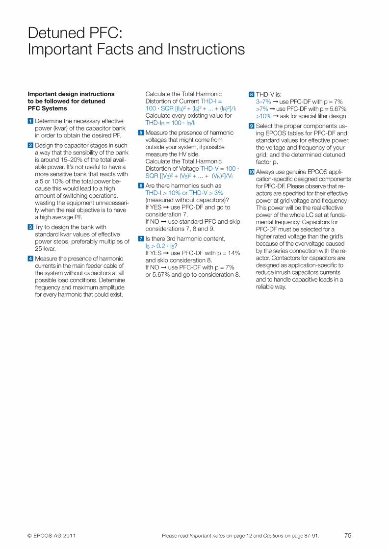
© EPCOS AG 2011 75Please read Important notes on page 12 and Cautions on page 87-91.
Detuned PFC: Important Facts and Instructions
Important design instructions to be followed for detuned PFC Systems
Determine the necessary effec tivepower (kvar) of the capacitor bankin order to obtain the desired PF.
Design the capacitor stages in sucha way that the sensibility of the bankis around 15–20% of the total avail-able power. It’s not useful to have amore sensitive bank that reacts witha 5 or 10% of the total power be-cause this would lead to a highamount of switching operations,wasting the equipment unnecessari-ly when the real objective is to havea high average PF.
Try to design the bank with standard kvar values of effectivepower steps, preferably multiples of25 kvar.
Measure the presence of harmoniccurrents in the main feeder cable ofthe system without capacitors at allpossible load conditions. Determinefrequency and maximum ampli tudefor every harmonic that could exist.
4
3
2
1
Calcu late the Total Harmonic Distortion of Current THD-I = 100 · SQR [(I3)2 + (I5)2 + ... + (IR)2]/IlCalculate every existing value forTHD-IR = 100 · IR/Il
Measure the presence of harmonicvoltages that might come from outside your system, if possible measure the HV side.Calculate the Total Harmonic Distortion of Voltage THD-V = 100 ·SQR [(V3)2 + (V5)2 + ... + (VN)2]/Vl
Are there harmonics such as THD-I > 10% or THD-V > 3% (measured without capacitors)?If YES � use PFC-DF and go toconsideration 7.If NO � use standard PFC and skipconsiderations 7, 8 and 9.
Is there 3rd harmonic content, I3 > 0.2 · I5? If YES � use PFC-DF with p = 14%and skip consideration 8.If NO � use PFC-DF with p = 7%or 5.67% and go to consideration 8.
7
6
5
THD-V is: 3–7% � use PFC-DF with p = 7% >7% � use PFC-DF with p = 5.67%>10% � ask for special filter design
Select the proper components us-ing EPCOS tables for PFC-DF andstandard values for effective power,the voltage and frequency of yourgrid, and the determined detunedfactor p.
Always use genuine EPCOS appli -cation-specific designed componentsfor PFC-DF. Please observe that re-actors are specified for their effectivepower at grid voltage and frequency.This power will be the real effectivepower of the whole LC set at funda-mental frequency. Capacitors forPFC-DF must be selected for a higher rated voltage than the grid’sbecause of the overvoltage causedby the series connection with the re-actor. Contactors for capacitors aredesigned as application-specific toreduce inrush capacitors currentsand to handle capacitive loads in areliable way.
9
8
10
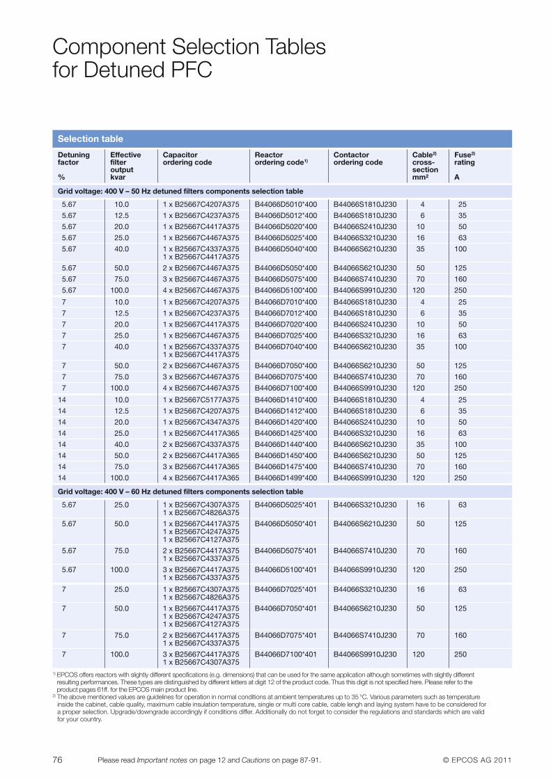
76 © EPCOS AG 2011Please read Important notes on page 12 and Cautions on page 87-91.
Component Selection Tables for Detuned PFC
Selection table
Detuning Effective Capacitor Reactor Contactor Cable2) Fuse2)
factor filter ordering code ordering code1) ordering code cross- ratingoutput section
% kvar mm2 A
Grid voltage: 400 V – 50 Hz detuned filters components selection table
5.67 10.0 1 x B25667C4207A375 B44066D5010*400 B44066S1810J230 4 25
5.67 12.5 1 x B25667C4237A375 B44066D5012*400 B44066S1810J230 6 35
5.67 20.0 1 x B25667C4417A375 B44066D5020*400 B44066S2410J230 10 50
5.67 25.0 1 x B25667C4467A375 B44066D5025*400 B44066S3210J230 16 63
5.67 40.0 1 x B25667C4337A375 B44066D5040*400 B44066S6210J230 35 1001 x B25667C4417A375
5.67 50.0 2 x B25667C4467A375 B44066D5050*400 B44066S6210J230 50 125
5.67 75.0 3 x B25667C4467A375 B44066D5075*400 B44066S7410J230 70 160
5.67 100.0 4 x B25667C4467A375 B44066D5100*400 B44066S9910J230 120 250
7 10.0 1 x B25667C4207A375 B44066D7010*400 B44066S1810J230 4 25
7 12.5 1 x B25667C4237A375 B44066D7012*400 B44066S1810J230 6 35
7 20.0 1 x B25667C4417A375 B44066D7020*400 B44066S2410J230 10 50
7 25.0 1 x B25667C4467A375 B44066D7025*400 B44066S3210J230 16 63
7 40.0 1 x B25667C4337A375 B44066D7040*400 B44066S6210J230 35 1001 x B25667C4417A375
7 50.0 2 x B25667C4467A375 B44066D7050*400 B44066S6210J230 50 125
7 75.0 3 x B25667C4467A375 B44066D7075*400 B44066S7410J230 70 160
7 100.0 4 x B25667C4467A375 B44066D7100*400 B44066S9910J230 120 250
14 10.0 1 x B25667C5177A375 B44066D1410*400 B44066S1810J230 4 25
14 12.5 1 x B25667C4207A375 B44066D1412*400 B44066S1810J230 6 35
14 20.0 1 x B25667C4347A375 B44066D1420*400 B44066S2410J230 10 50
14 25.0 1 x B25667C4417A365 B44066D1425*400 B44066S3210J230 16 63
14 40.0 2 x B25667C4337A375 B44066D1440*400 B44066S6210J230 35 100
14 50.0 2 x B25667C4417A365 B44066D1450*400 B44066S6210J230 50 125
14 75.0 3 x B25667C4417A365 B44066D1475*400 B44066S7410J230 70 160
14 100.0 4 x B25667C4417A365 B44066D1499*400 B44066S9910J230 120 250
Grid voltage: 400 V – 60 Hz detuned filters components selection table
5.67 25.0 1 x B25667C4307A375 B44066D5025*401 B44066S3210J230 16 631 x B25667C4826A375
5.67 50.0 1 x B25667C4417A375 B44066D5050*401 B44066S6210J230 50 1251 x B25667C4247A3751 x B25667C4127A375
5.67 75.0 2 x B25667C4417A375 B44066D5075*401 B44066S7410J230 70 1601 x B25667C4337A375
5.67 100.0 3 x B25667C4417A375 B44066D5100*401 B44066S9910J230 120 2501 x B25667C4337A375
7 25.0 1 x B25667C4307A375 B44066D7025*401 B44066S3210J230 16 631 x B25667C4826A375
7 50.0 1 x B25667C4417A375 B44066D7050*401 B44066S6210J230 50 1251 x B25667C4247A3751 x B25667C4127A375
7 75.0 2 x B25667C4417A375 B44066D7075*401 B44066S7410J230 70 1601 x B25667C4337A375
7 100.0 3 x B25667C4417A375 B44066D7100*401 B44066S9910J230 120 2501 x B25667C4307A375
1) EPCOS offers reactors with slightly different specifications (e.g. dimensions) that can be used for the same application although sometimes with slightly differentresulting performances. These types are distinguished by different letters at digit 12 of the product code. Thus this digit is not specified here. Please refer to the product pages 61ff. for the EPCOS main product line.
2) The above mentioned values are guidelines for operation in normal conditions at ambient temperatures up to 35 °C. Various parameters such as temperatureinside the cabinet, cable quality, maximum cable insulation temperature, single or multi core cable, cable lengh and laying system have to be considered for a proper selection. Upgrade/downgrade accordingly if conditions differ. Additionally do not forget to consider the regulations and standards which are validfor your country.
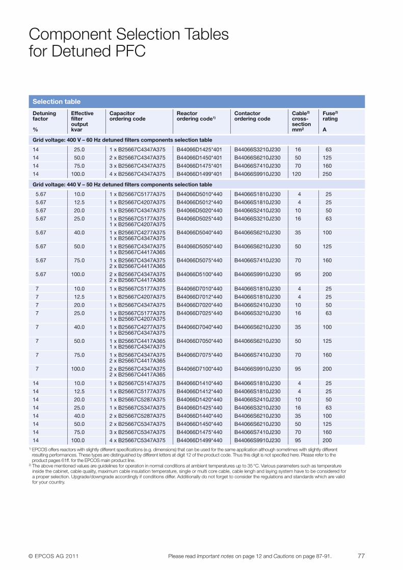
© EPCOS AG 2011 77Please read Important notes on page 12 and Cautions on page 87-91.
Component Selection Tables for Detuned PFC
Selection table
Detuning Effective Capacitor Reactor Contactor Cable2) Fuse2)
factor filter ordering code ordering code1) ordering code cross- ratingoutput section
% kvar mm2 A
Grid voltage: 400 V – 60 Hz detuned filters components selection table
14 25.0 1 x B25667C4347A375 B44066D1425*401 B44066S3210J230 16 63
14 50.0 2 x B25667C4347A375 B44066D1450*401 B44066S6210J230 50 125
14 75.0 3 x B25667C4347A375 B44066D1475*401 B44066S7410J230 70 160
14 100.0 4 x B25667C4347A375 B44066D1499*401 B44066S9910J230 120 250
Grid voltage: 440 V – 50 Hz detuned filters components selection table
5.67 10.0 1 x B25667C5177A375 B44066D5010*440 B44066S1810J230 4 25
5.67 12.5 1 x B25667C4207A375 B44066D5012*440 B44066S1810J230 4 25
5.67 20.0 1 x B25667C4347A375 B44066D5020*440 B44066S2410J230 10 50
5.67 25.0 1 x B25667C5177A375 B44066D5025*440 B44066S3210J230 16 631 x B25667C4207A375
5.67 40.0 1 x B25667C4277A375 B44066D5040*440 B44066S6210J230 35 1001 x B25667C4347A375
5.67 50.0 1 x B25667C4347A375 B44066D5050*440 B44066S6210J230 50 1251 x B25667C4417A365
5.67 75.0 1 x B25667C4347A375 B44066D5075*440 B44066S7410J230 70 1602 x B25667C4417A365
5.67 100.0 2 x B25667C4347A375 B44066D5100*440 B44066S9910J230 95 2002 x B25667C4417A365
7 10.0 1 x B25667C5177A375 B44066D7010*440 B44066S1810J230 4 25
7 12.5 1 x B25667C4207A375 B44066D7012*440 B44066S1810J230 4 25
7 20.0 1 x B25667C4347A375 B44066D7020*440 B44066S2410J230 10 50
7 25.0 1 x B25667C5177A375 B44066D7025*440 B44066S3210J230 16 631 x B25667C4207A375
7 40.0 1 x B25667C4277A375 B44066D7040*440 B44066S6210J230 35 1001 x B25667C4347A375
7 50.0 1 x B25667C4417A365 B44066D7050*440 B44066S6210J230 50 1251 x B25667C4347A375
7 75.0 1 x B25667C4347A375 B44066D7075*440 B44066S7410J230 70 1602 x B25667C4417A365
7 100.0 2 x B25667C4347A375 B44066D7100*440 B44066S9910J230 95 2002 x B25667C4417A365
14 10.0 1 x B25667C5147A375 B44066D1410*440 B44066S1810J230 4 25
14 12.5 1 x B25667C5177A375 B44066D1412*440 B44066S1810J230 4 25
14 20.0 1 x B25667C5287A375 B44066D1420*440 B44066S2410J230 10 50
14 25.0 1 x B25667C5347A375 B44066D1425*440 B44066S3210J230 16 63
14 40.0 2 x B25667C5287A375 B44066D1440*440 B44066S6210J230 35 100
14 50.0 2 x B25667C5347A375 B44066D1450*440 B44066S6210J230 50 125
14 75.0 3 x B25667C5347A375 B44066D1475*440 B44066S7410J230 70 160
14 100.0 4 x B25667C5347A375 B44066D1499*440 B44066S9910J230 95 2001) EPCOS offers reactors with slightly different specifications (e.g. dimensions) that can be used for the same application although sometimes with slightly different
resulting performances. These types are distinguished by different letters at digit 12 of the product code. Thus this digit is not specified here. Please refer to the product pages 61ff. for the EPCOS main product line.
2) The above mentioned values are guidelines for operation in normal conditions at ambient temperatures up to 35 °C. Various parameters such as temperatureinside the cabinet, cable quality, maximum cable insulation temperature, single or multi core cable, cable lengh and laying system have to be considered for a proper selection. Upgrade/downgrade accordingly if conditions differ. Additionally do not forget to consider the regulations and standards which are validfor your country.
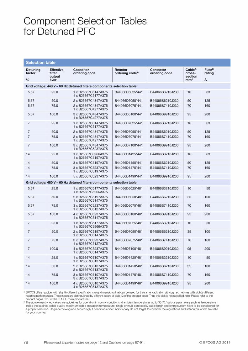
78 © EPCOS AG 2011Please read Important notes on page 12 and Cautions on page 87-91.
Component Selection Tables for Detuned PFC
Selection table
Detuning Effective Capacitor Reactor Contactor Cable2) Fuse2)
factor filter ordering code ordering code1) ordering code cross- ratingoutput section
% kvar mm2 A
Grid voltage: 440 V – 60 Hz detuned filters components selection table
5.67 25.0 1 x B25667C5147A375 B44066D5025*441 B44066S3210J230 16 631 x B25667C5177A375
5.67 50.0 2 x B25667C4347A375 B44066D5050*441 B44066S6210J230 50 125
5.67 75.0 2 x B25667C4347A375 B44066D5075*441 B44066S7410J230 70 1601 x B25667C4277A375
5.67 100.0 3 x B25667C4347A375 B44066D5100*441 B44066S9910J230 95 2001 x B25667C4277A375
7 25.0 1 x B25667C5147A375 B44066D7025*441 B44066S3210J230 16 631 x B25667C5177A375
7 50.0 2 x B25667C4347A375 B44066D7050*441 B44066S6210J230 50 125
7 75.0 2 x B25667C4347A375 B44066D7075*441 B44066S7410J230 70 1601 x B25667C4277A375
7 100.0 3 x B25667C4347A375 B44066D7100*441 B44066S9910J230 95 2001 x B25667C5237A375
14 25.0 1 x B25667C5966A375 B44066D1425*441 B44066S3210J230 16 631 x B25667C5197A375
14 50.0 3 x B25667C5197A375 B44066D1450*441 B44066S6210J230 50 125
14 75.0 3 x B25667C5237A375 B44066D1475*441 B44066S7410J230 70 1601 x B25667C5197A375
14 100.0 5 x B25667C5237A375 B44066D1499*441 B44066S9910J230 95 200
Grid voltage: 480 V – 60 Hz detuned filters components selection table
5.67 25.0 1 x B25667C5177A375 B44066D5025*481 B44066S3210J230 10 501 x B25667C5966A375
5.67 50.0 2 x B25667C5197A375 B44066D5050*481 B44066S6210J230 35 1001 x B25667C5147A375
5.67 75.0 3 x B25667C5237A375 B44066D5075*481 B44066S7410J230 70 1601 x B25667C5127A375
5.67 100.0 4 x B25667C5237A375 B44066D5100*481 B44066S9910J230 95 2001 x B25667C5147A375
7 25.0 1 x B25667C5177A375 B44066D7025*481 B44066S3210J230 10 501 x B25667C5966A375
7 50.0 2 x B25667C5197A375 B44066D7050*481 B44066S6210J230 35 1001 x B25667C5147A375
7 75.0 3 x B25667C5237A375 B44066D7075*481 B44066S7410J230 70 1601 x B25667C5127A375
7 100.0 4 x B25667C5237A375 B44066D7100*481 B44066S9910J230 95 2001 x B25667C5147A375
14 25.0 1 x B25667C6107A375 B44066D1425*481 B44066S3210J230 10 501 x B25667C6137A375
14 50.0 2 x B25667C6107A375 B44066D1450*481 B44066S6210J230 35 1002 x B25667C6137A375
14 75.0 3 x B25667C6107A375 B44066D1475*481 B44066S7410J230 70 1603 x B25667C6137A375
14 100.0 4 x B25667C6107A375 B44066D1499*481 B44066S9910J230 95 2004 x B25667C6137A375
1) EPCOS offers reactors with slightly different specifications (e.g. dimensions) that can be used for the same application although sometimes with slightly differentresulting performances. These types are distinguished by different letters at digit 12 of the product code. Thus this digit is not specified here. Please refer to the product pages 61ff. for the EPCOS main product line.
2) The above mentioned values are guidelines for operation in normal conditions at ambient temperatures up to 35 °C. Various parameters such as temperatureinside the cabinet, cable quality, maximum cable insulation temperature, single or multi core cable, cable lengh and laying system have to be considered for a proper selection. Upgrade/downgrade accordingly if conditions differ. Additionally do not forget to consider the regulations and standards which are validfor your country.
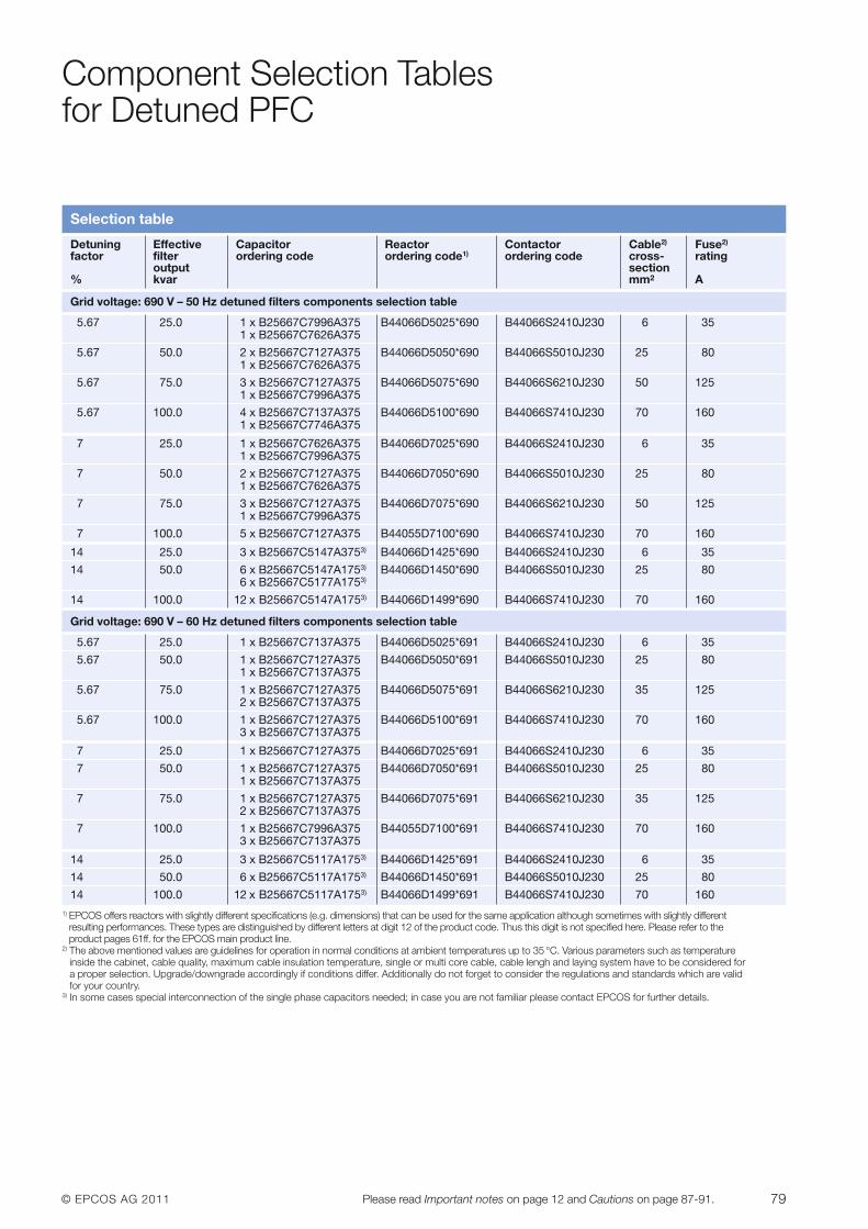
© EPCOS AG 2011 79Please read Important notes on page 12 and Cautions on page 87-91.
Component Selection Tables for Detuned PFC
Selection table
Detuning Effective Capacitor Reactor Contactor Cable2) Fuse2)
factor filter ordering code ordering code1) ordering code cross- ratingoutput section
% kvar mm2 A
Grid voltage: 690 V – 50 Hz detuned filters components selection table
5.67 25.0 1 x B25667C7996A375 B44066D5025*690 B44066S2410J230 6 351 x B25667C7626A375
5.67 50.0 2 x B25667C7127A375 B44066D5050*690 B44066S5010J230 25 801 x B25667C7626A375
5.67 75.0 3 x B25667C7127A375 B44066D5075*690 B44066S6210J230 50 1251 x B25667C7996A375
5.67 100.0 4 x B25667C7137A375 B44066D5100*690 B44066S7410J230 70 1601 x B25667C7746A375
7 25.0 1 x B25667C7626A375 B44066D7025*690 B44066S2410J230 6 351 x B25667C7996A375
7 50.0 2 x B25667C7127A375 B44066D7050*690 B44066S5010J230 25 801 x B25667C7626A375
7 75.0 3 x B25667C7127A375 B44066D7075*690 B44066S6210J230 50 1251 x B25667C7996A375
7 100.0 5 x B25667C7127A375 B44055D7100*690 B44066S7410J230 70 160
14 25.0 3 x B25667C5147A3753) B44066D1425*690 B44066S2410J230 6 35
14 50.0 6 x B25667C5147A1753) B44066D1450*690 B44066S5010J230 25 806 x B25667C5177A1753)
14 100.0 12 x B25667C5147A1753) B44066D1499*690 B44066S7410J230 70 160
Grid voltage: 690 V – 60 Hz detuned filters components selection table
5.67 25.0 1 x B25667C7137A375 B44066D5025*691 B44066S2410J230 6 35
5.67 50.0 1 x B25667C7127A375 B44066D5050*691 B44066S5010J230 25 801 x B25667C7137A375
5.67 75.0 1 x B25667C7127A375 B44066D5075*691 B44066S6210J230 35 1252 x B25667C7137A375
5.67 100.0 1 x B25667C7127A375 B44066D5100*691 B44066S7410J230 70 1603 x B25667C7137A375
7 25.0 1 x B25667C7127A375 B44066D7025*691 B44066S2410J230 6 35
7 50.0 1 x B25667C7127A375 B44066D7050*691 B44066S5010J230 25 801 x B25667C7137A375
7 75.0 1 x B25667C7127A375 B44066D7075*691 B44066S6210J230 35 1252 x B25667C7137A375
7 100.0 1 x B25667C7996A375 B44055D7100*691 B44066S7410J230 70 1603 x B25667C7137A375
14 25.0 3 x B25667C5117A1753) B44066D1425*691 B44066S2410J230 6 35
14 50.0 6 x B25667C5117A1753) B44066D1450*691 B44066S5010J230 25 80
14 100.0 12 x B25667C5117A1753) B44066D1499*691 B44066S7410J230 70 1601) EPCOS offers reactors with slightly different specifications (e.g. dimensions) that can be used for the same application although sometimes with slightly different
resulting performances. These types are distinguished by different letters at digit 12 of the product code. Thus this digit is not specified here. Please refer to the product pages 61ff. for the EPCOS main product line.
2) The above mentioned values are guidelines for operation in normal conditions at ambient temperatures up to 35 °C. Various parameters such as temperatureinside the cabinet, cable quality, maximum cable insulation temperature, single or multi core cable, cable lengh and laying system have to be considered for a proper selection. Upgrade/downgrade accordingly if conditions differ. Additionally do not forget to consider the regulations and standards which are validfor your country.
3) In some cases special interconnection of the single phase capacitors needed; in case you are not familiar please contact EPCOS for further details.
80 © EPCOS AG 2011Please read Important notes on page 12 and Cautions on page 87-91.
Dynamic PFC:Important Facts and Instructions
shortens the life expectancy of the capacitor, but also increases the riskof premature failure and in the worstcase represents a potential safety risk.
But furthermore the capacitor itself isspecified for a limited number ofswitching operations per year. Thestandard IEC 60831 gives an accept-able value of 5 000 switching opera-tions per year, a value far belowswitching numbers up to 100 000 thatmay be required per year in dynamicapplications. Such large switchingnumbers and the respective overvolt-ages and overcurrents during eachswitching operation are likely to dam-age the capacitor and may lead to avery early capacitor failure.
In dynamic PFC systems, the capaci-tor contactors are replaced by thyris-tor modules that are suitable for anearby unlimited number of switchingoperations as there is no mechanicalwear-off. Thyristor modules featureelectronic semiconductor switchesthat are able to react to a changing re-active power demand on the ms scaleand that can switch capacitors withoutadditional stress. The EPCOS TSM-thyristor switches keep the capacitorsat the peak value of the grid voltageand connect them only when the gridreaches this peak voltage value. Thusthe capacitors are switched currentfree and inrush currents that can reachvalues of 200 times the nominal cur-rent for conventional contactors areavoided. Additionally capacitor dis-
charge times up to 75 s as necessaryfor conventional PFC are not requiredhere.
In summary dynamic PFC does notonly prevent wear-off of the capacitorsand the switches and increases thusthe lifetime of a PFC system and itssafety. It also increases the powerquality in the grid essentially as it canalmost react in real time to reactivepower demands. Fast enough for ex-ample, to take care of motor start upeffects or spot welding requirements.
EPCOS offers all necessary key com-ponents to set up a dynamic PFC sys-tems as the thyristor modules (TSM,see page 57), the required fast transis-tor output controllers (BR6000-T, page40 ff), and the EPCOS standard reac-tor (page 61) and of course capacitor series (page 13). A further help tocompose such a system for a largenumber of situations is given by thedynamic PFC selection tables on page 76 ff.
Note: The recommendations given inthe selection tables are meant as asupport tool. EPCOS does not takeover any responsibility for the designas apart from the theoretical condi-tions the prevailing circumstances inthe application have to be taken intoaccount.
General
Conventional PFC systems quicklyreach their limits when they have todeal with fast changing loads. Applica-tions like rolling mills, steel presses,wind turbines, container cranes andlarge buildings include a huge amountof electric consumers that require a reactive power adjustment on the msscale. Production equipment, eleva-tors, chillers, and other electric de-vices not only require such dynamicreactions of the power factor compen-sation equipment, they also lead verysoon to a total number of switchingsthat exceeds the specifications ofstandard electromechanical contac-tors by far.
In conventional PFC systems, stan-dard capacitor contactors are used toswitch capacitor steps on and off.These electromechanical devices offerbetween 100 000 and 200 000switching operations in total duringtheir life time which means that in suchan application they reach their life ex-pectancy after 1 to 2 years already. Ithas to be mentioned that capacitorsare much stricter limited with regard to the permitted annual number ofswitching operations (IEC 60831). Thistypically results in destruction of theirinrush current damping capability andmay also damage the contacts in themain power circuit. Burnt main con-tacts may produce oscillation or “un-clean” (re-bouncing) switching opera-tions. This massive overload not only
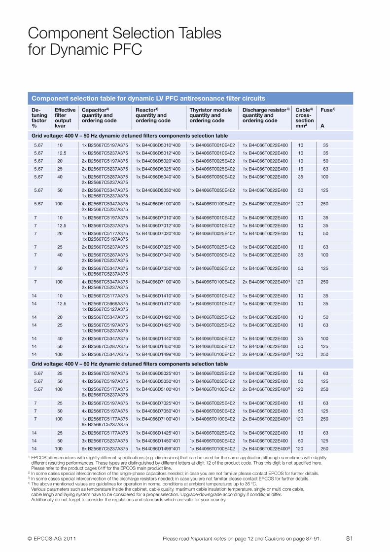
© EPCOS AG 2011 81Please read Important notes on page 12 and Cautions on page 87-91.
Component Selection Tables for Dynamic PFC
Component selection table for dynamic LV PFC antiresonance filter circuits
De- Effective Capacitor2) Reactor1) Thyristor module Discharge resistor3) Cable4) Fuse4)
tuning filter quantity and quantity and quantity and quantity and cross-factor output ordering code ordering code ordering code ordering code section% kvar mm2 A
Grid voltage: 400 V – 50 Hz dynamic detuned filters components selection table
5.67 10 1x B25667C5197A375 1x B44066D5010*400 1x B44066T0010E402 1x B44066T0022E400 10 35
5.67 12.5 1x B25667C5237A375 1x B44066D5012*400 1x B44066T0010E402 1x B44066T0022E400 10 35
5.67 20 2x B25667C5197A375 1x B44066D5020*400 1x B44066T0025E402 1x B44066T0022E400 10 50
5.67 25 2x B25667C5237A375 1x B44066D5025*400 1x B44066T0025E402 1x B44066T0022E400 16 63
5.67 40 1x B25667C5287A375 1x B44066D5040*400 1x B44066T0050E402 1x B44066T0022E400 35 1002x B25667C5237A375
5.67 50 2x B25667C5347A375 1x B44066D5050*400 1x B44066T0050E402 1x B44066T0022E400 50 1251x B25667C5237A375
5.67 100 4x B25667C5347A375 1x B44066D5100*400 1x B44066T0100E402 2x B44066T0022E4002) 120 2502x B25667C5237A375
7 10 1x B25667C5197A375 1x B44066D7010*400 1x B44066T0010E402 1x B44066T0022E400 10 35
7 12.5 1x B25667C5237A375 1x B44066D7012*400 1x B44066T0010E402 1x B44066T0022E400 10 35
7 20 1x B25667C5177A375 1x B44066D7020*400 1x B44066T0025E402 1x B44066T0022E400 10 501x B25667C5197A375
7 25 2x B25667C5237A375 1x B44066D7025*400 1x B44066T0025E402 1x B44066T0022E400 16 63
7 40 1x B25667C5287A375 1x B44066D7040*400 1x B44066T0050E402 1x B44066T0022E400 35 1002x B25667C5237A375
7 50 2x B25667C5347A375 1x B44066D7050*400 1x B44066T0050E402 1x B44066T0022E400 50 1251x B25667C5237A375
7 100 4x B25667C5347A375 1x B44066D7100*400 1x B44066T0100E402 2x B44066T0022E4003) 120 2502x B25667C5237A375
14 10 1x B25667C5177A375 1x B44066D1410*400 1x B44066T0010E402 1x B44066T0022E400 10 35
14 12.5 1x B25667C5966A375 1x B44066D1412*400 1x B44066T0010E402 1x B44066T0022E400 10 351x B25667C5127A375
14 20 1x B25667C5347A375 1x B44066D1420*400 1x B44066T0025E402 1x B44066T0022E400 10 50
14 25 1x B25667C5197A375 1x B44066D1425*400 1x B44066T0025E402 1x B44066T0022E400 16 631x B25667C5237A375
14 40 2x B25667C5347A375 1x B44066D1440*400 1x B44066T0050E402 1x B44066T0022E400 35 100
14 50 3x B25667C5287A375 1x B44066D1450*400 1x B44066T0050E402 1x B44066T0022E400 50 125
14 100 5x B25667C5347A375 1x B44066D1499*400 1x B44066T0100E402 2x B44066T0022E4003) 120 250
Grid voltage: 400 V – 60 Hz dynamic detuned filters components selection table
5.67 25 2x B25667C5197A375 1x B44066D5025*401 1x B44066T0025E402 1x B44066T0022E400 16 63
5.67 50 4x B25667C5197A375 1x B44066D5050*401 1x B44066T0050E402 1x B44066T0022E400 50 125
5.67 100 1x B25667C5177A375 1x B44066D5100*401 1x B44066T0100E402 2x B44066T0022E4003) 120 2506x B25667C5237A375
7 25 2x B25667C5197A375 1x B44066D7025*401 1x B44066T0025E402 1x B44066T0022E400 16 63
7 50 4x B25667C5197A375 1x B44066D7050*401 1x B44066T0050E402 1x B44066T0022E400 50 125
7 100 1x B25667C5177A375 1x B44066D7100*401 1x B44066T0100E402 2x B44066T0022E4003) 120 2506x B25667C5237A375
14 25 2x B25667C5177A375 1x B44066D1425*401 1x B44066T0025E402 1x B44066T0022E400 16 63
14 50 3x B25667C5237A375 1x B44066D1450*401 1x B44066T0050E402 1x B44066T0022E400 50 125
14 100 6x B25667C5237A375 1x B44066D1499*401 1x B44066T0100E402 2x B44066T0022E4003) 120 250
1) EPCOS offers reactors with slightly different specifications (e.g. dimensions) that can be used for the same application although sometimes with slightly different resulting performances. These types are distinguished by different letters at digit 12 of the product code. Thus this digit is not specified here. Please refer to the product pages 61ff for the EPCOS main product line.
2) In some cases special interconnection of the single-phase capacitors needed; in case you are not familiar please contact EPCOS for further details.3) In some cases special interconnection of the discharge resistors needed; in case you are not familiar please contact EPCOS for further details.4) The above mentioned values are guidelines for operation in normal conditions at ambient temperatures up to 35 °C.
Various parameters such as temperature inside the cabinet, cable quality, maximum cable insulation temperature, single or multi core cable, cable lengh and laying system have to be considered for a proper selection. Upgrade/downgrade accordingly if conditions differ. Additionally do not forget to consider the regulations and standards which are valid for your country.
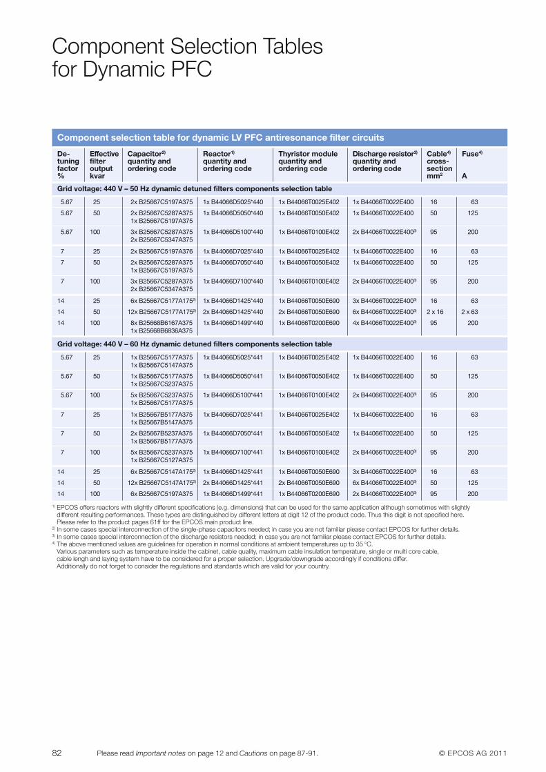
82 © EPCOS AG 2011Please read Important notes on page 12 and Cautions on page 87-91.
Component Selection Tables for Dynamic PFC
Component selection table for dynamic LV PFC antiresonance filter circuits
De- Effective Capacitor2) Reactor1) Thyristor module Discharge resistor3) Cable4) Fuse4)
tuning filter quantity and quantity and quantity and quantity and cross-factor output ordering code ordering code ordering code ordering code section% kvar mm2 A
Grid voltage: 440 V – 50 Hz dynamic detuned filters components selection table
5.67 25 2x B25667C5197A375 1x B44066D5025*440 1x B44066T0025E402 1x B44066T0022E400 16 63
5.67 50 2x B25667C5287A375 1x B44066D5050*440 1x B44066T0050E402 1x B44066T0022E400 50 1251x B25667C5197A375
5.67 100 3x B25667C5287A375 1x B44066D5100*440 1x B44066T0100E402 2x B44066T0022E4003) 95 2002x B25667C5347A375
7 25 2x B25667C5197A376 1x B44066D7025*440 1x B44066T0025E402 1x B44066T0022E400 16 63
7 50 2x B25667C5287A375 1x B44066D7050*440 1x B44066T0050E402 1x B44066T0022E400 50 1251x B25667C5197A375
7 100 3x B25667C5287A375 1x B44066D7100*440 1x B44066T0100E402 2x B44066T0022E4003) 95 2002x B25667C5347A375
14 25 6x B25667C5177A1752) 1x B44066D1425*440 1x B44066T0050E690 3x B44066T0022E4003) 16 63
14 50 12x B25667C5177A1752) 2x B44066D1425*440 2x B44066T0050E690 6x B44066T0022E4003) 2 x 16 2 x 63
14 100 8x B25668B6167A375 1x B44066D1499*440 1x B44066T0200E690 4x B44066T0022E4003) 95 2001x B25668B6836A375
Grid voltage: 440 V – 60 Hz dynamic detuned filters components selection table
5.67 25 1x B25667C5177A375 1x B44066D5025*441 1x B44066T0025E402 1x B44066T0022E400 16 631x B25667C5147A375
5.67 50 1x B25667C5177A375 1x B44066D5050*441 1x B44066T0050E402 1x B44066T0022E400 50 1251x B25667C5237A375
5.67 100 5x B25667C5237A375 1x B44066D5100*441 1x B44066T0100E402 2x B44066T0022E4003) 95 2001x B25667C5177A375
7 25 1x B25667B5177A375 1x B44066D7025*441 1x B44066T0025E402 1x B44066T0022E400 16 631x B25667B5147A375
7 50 2x B25667B5237A375 1x B44066D7050*441 1x B44066T0050E402 1x B44066T0022E400 50 1251x B25667B5177A375
7 100 5x B25667C5237A375 1x B44066D7100*441 1x B44066T0100E402 2x B44066T0022E4003) 95 2001x B25667C5127A375
14 25 6x B25667C5147A1752) 1x B44066D1425*441 1x B44066T0050E690 3x B44066T0022E4003) 16 63
14 50 12x B25667C5147A1752) 2x B44066D1425*441 2x B44066T0050E690 6x B44066T0022E4003) 50 125
14 100 6x B25667C5197A375 1x B44066D1499*441 1x B44066T0200E690 2x B44066T0022E4003) 95 200
1) EPCOS offers reactors with slightly different specifications (e.g. dimensions) that can be used for the same application although sometimes with slightly different resulting performances. These types are distinguished by different letters at digit 12 of the product code. Thus this digit is not specified here. Please refer to the product pages 61ff for the EPCOS main product line.
2) In some cases special interconnection of the single-phase capacitors needed; in case you are not familiar please contact EPCOS for further details.3) In some cases special interconnection of the discharge resistors needed; in case you are not familiar please contact EPCOS for further details.4) The above mentioned values are guidelines for operation in normal conditions at ambient temperatures up to 35 °C.
Various parameters such as temperature inside the cabinet, cable quality, maximum cable insulation temperature, single or multi core cable, cable lengh and laying system have to be considered for a proper selection. Upgrade/downgrade accordingly if conditions differ. Additionally do not forget to consider the regulations and standards which are valid for your country.
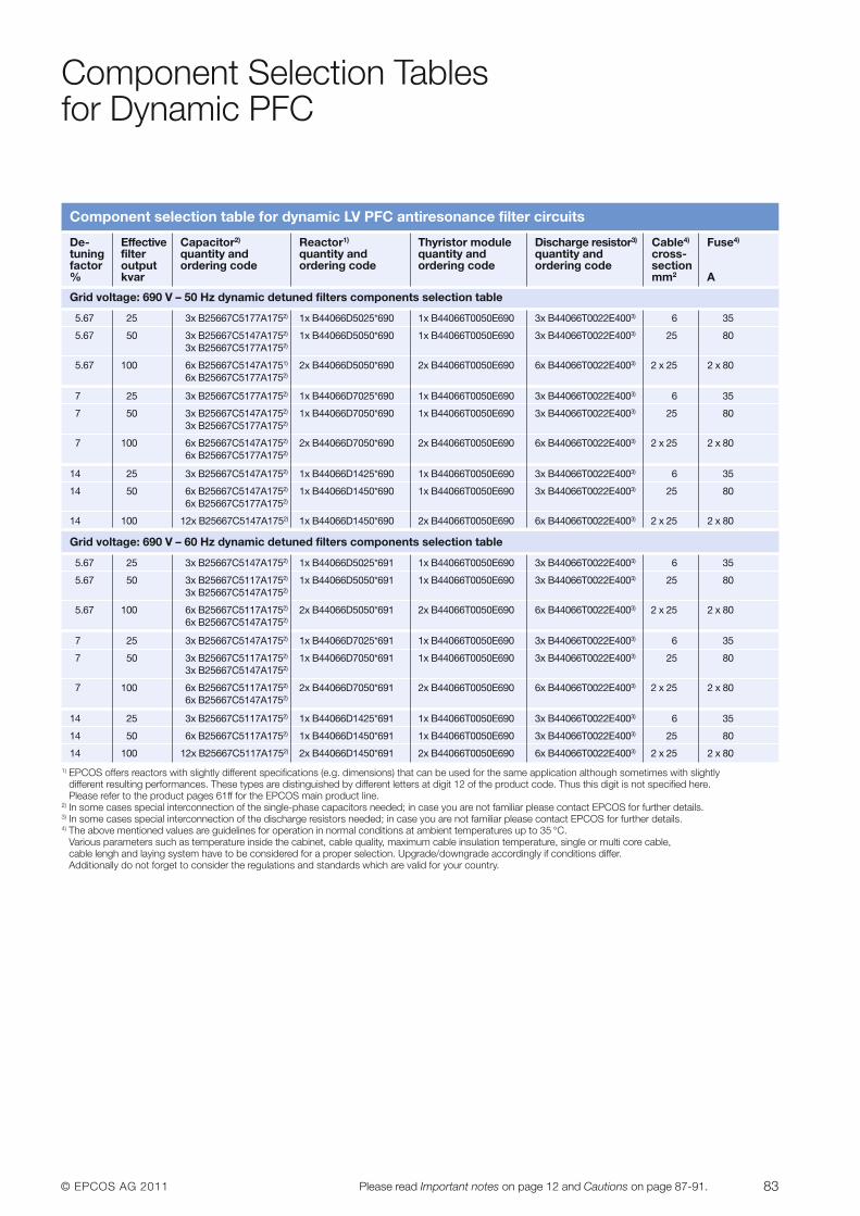
© EPCOS AG 2011 83Please read Important notes on page 12 and Cautions on page 87-91.
Component Selection Tables for Dynamic PFC
Component selection table for dynamic LV PFC antiresonance filter circuits
De- Effective Capacitor2) Reactor1) Thyristor module Discharge resistor3) Cable4) Fuse4)
tuning filter quantity and quantity and quantity and quantity and cross-factor output ordering code ordering code ordering code ordering code section% kvar mm2 A
Grid voltage: 690 V – 50 Hz dynamic detuned filters components selection table
5.67 25 3x B25667C5177A1752) 1x B44066D5025*690 1x B44066T0050E690 3x B44066T0022E4003) 6 35
5.67 50 3x B25667C5147A1752) 1x B44066D5050*690 1x B44066T0050E690 3x B44066T0022E4003) 25 803x B25667C5177A1752)
5.67 100 6x B25667C5147A1751) 2x B44066D5050*690 2x B44066T0050E690 6x B44066T0022E4003) 2 x 25 2 x 806x B25667C5177A1752)
7 25 3x B25667C5177A1752) 1x B44066D7025*690 1x B44066T0050E690 3x B44066T0022E4003) 6 35
7 50 3x B25667C5147A1752) 1x B44066D7050*690 1x B44066T0050E690 3x B44066T0022E4003) 25 803x B25667C5177A1752)
7 100 6x B25667C5147A1752) 2x B44066D7050*690 2x B44066T0050E690 6x B44066T0022E4003) 2 x 25 2 x 806x B25667C5177A1752)
14 25 3x B25667C5147A1752) 1x B44066D1425*690 1x B44066T0050E690 3x B44066T0022E4003) 6 35
14 50 6x B25667C5147A1752) 1x B44066D1450*690 1x B44066T0050E690 3x B44066T0022E4003) 25 806x B25667C5177A1752)
14 100 12x B25667C5147A1752) 1x B44066D1450*690 2x B44066T0050E690 6x B44066T0022E4003) 2 x 25 2 x 80
Grid voltage: 690 V – 60 Hz dynamic detuned filters components selection table
5.67 25 3x B25667C5147A1752) 1x B44066D5025*691 1x B44066T0050E690 3x B44066T0022E4003) 6 35
5.67 50 3x B25667C5117A1752) 1x B44066D5050*691 1x B44066T0050E690 3x B44066T0022E4003) 25 803x B25667C5147A1752)
5.67 100 6x B25667C5117A1752) 2x B44066D5050*691 2x B44066T0050E690 6x B44066T0022E4003) 2 x 25 2 x 806x B25667C5147A1752)
7 25 3x B25667C5147A1752) 1x B44066D7025*691 1x B44066T0050E690 3x B44066T0022E4003) 6 35
7 50 3x B25667C5117A1752) 1x B44066D7050*691 1x B44066T0050E690 3x B44066T0022E4003) 25 803x B25667C5147A1752)
7 100 6x B25667C5117A1752) 2x B44066D7050*691 2x B44066T0050E690 6x B44066T0022E4003) 2 x 25 2 x 806x B25667C5147A1752)
14 25 3x B25667C5117A1752) 1x B44066D1425*691 1x B44066T0050E690 3x B44066T0022E4003) 6 35
14 50 6x B25667C5117A1752) 1x B44066D1450*691 1x B44066T0050E690 3x B44066T0022E4003) 25 80
14 100 12x B25667C5117A1752) 2x B44066D1450*691 2x B44066T0050E690 6x B44066T0022E4003) 2 x 25 2 x 80
1) EPCOS offers reactors with slightly different specifications (e.g. dimensions) that can be used for the same application although sometimes with slightly different resulting performances. These types are distinguished by different letters at digit 12 of the product code. Thus this digit is not specified here. Please refer to the product pages 61ff for the EPCOS main product line.
2) In some cases special interconnection of the single-phase capacitors needed; in case you are not familiar please contact EPCOS for further details.3) In some cases special interconnection of the discharge resistors needed; in case you are not familiar please contact EPCOS for further details.4) The above mentioned values are guidelines for operation in normal conditions at ambient temperatures up to 35 °C.
Various parameters such as temperature inside the cabinet, cable quality, maximum cable insulation temperature, single or multi core cable, cable lengh and laying system have to be considered for a proper selection. Upgrade/downgrade accordingly if conditions differ. Additionally do not forget to consider the regulations and standards which are valid for your country.
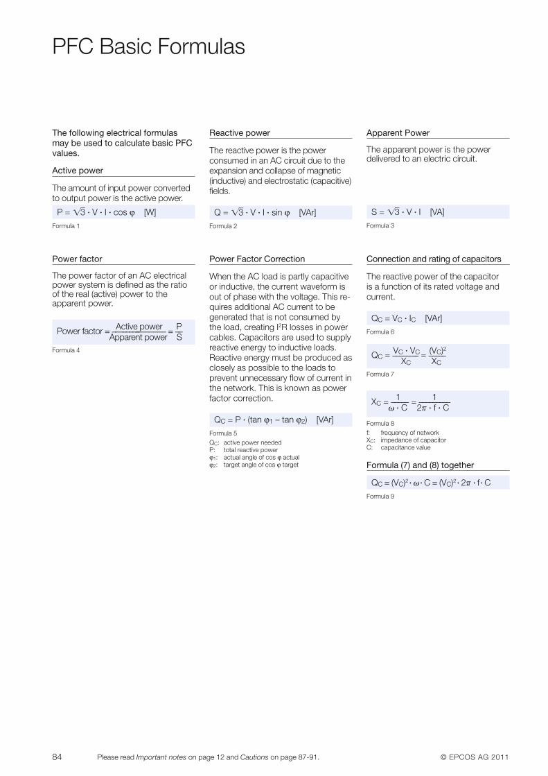
84 © EPCOS AG 2011Please read Important notes on page 12 and Cautions on page 87-91.
PFC Basic Formulas
The following electrical formulasmay be used to calculate basic PFCvalues.
Active power
The amount of input power convertedto output power is the active power.
P = ��3 · V · I · cos ϕ [W]Formula 1
Reactive power
The reactive power is the power consumed in an AC circuit due to theexpansion and collapse of magnetic(inductive) and electrostatic (capacitive)fields.
Q = ��3 · V · I · sin ϕ [VAr]Formula 2
Apparent Power
The apparent power is the power delivered to an electric circuit.
S = ��3 · V · I [VA]Formula 3
Power factor
The power factor of an AC electricalpower system is defined as the ratioof the real (active) power to the apparent power.
Active power PPower factor = ––––––––––––––– = ––Apparent power S
Formula 4
Power Factor Correction
When the AC load is partly capacitiveor inductive, the current waveform isout of phase with the voltage. This re-quires additional AC current to begenerated that is not consumed bythe load, creating I2R losses in powercables. Capacitors are used to supplyreactive energy to inductive loads.Reactive energy must be produced asclosely as possible to the loads toprevent unnecessary flow of current inthe network. This is known as powerfactor correction.
QC = P · (tan ϕ1 – tan ϕ2) [VAr]Formula 5QC: active power neededP: total reactive powerϕ1: actual angle of cos ϕ actualϕ2: target angle of cos ϕ target
Connection and rating of capacitors
The reactive power of the capacitor is a function of its rated voltage andcurrent.
QC = VC · IC [VAr]Formula 6
VC · VC (VC)2QC = –––––––– = –––––XC XC
Formula 7
Formula 8f: frequency of networkXC: impedance of capacitorC: capacitance value
Formula (7) and (8) together
QC = (VC)2 · � · C = (VC)2 · 2� · f · CFormula 9
1 1XC = ––––– = –––––––––� · C 2� · f · C
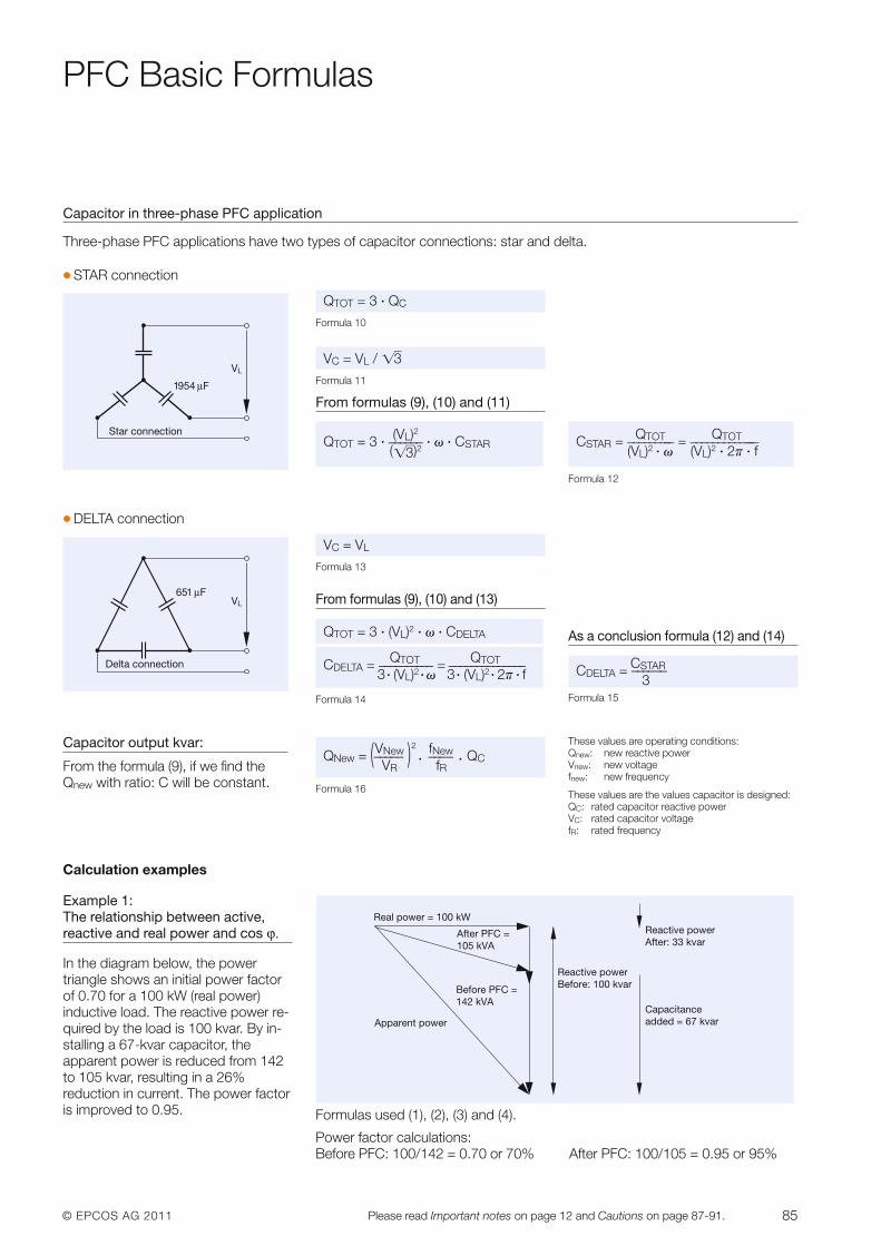
© EPCOS AG 2011 85Please read Important notes on page 12 and Cautions on page 87-91.
PFC Basic Formulas
Capacitor in three-phase PFC application
Three-phase PFC applications have two types of capacitor connections: star and delta.
� DELTA connection
VC = VL
Formula 13
From formulas (9), (10) and (13)
Formula 14
As a conclusion formula (12) and (14)
CSTARCDELTA = ––––––3
Formula 15
QTOT = 3 · (VL)2 · � · CDELTA
QTOT QTOTCDELTA = –––––––––– = ––––––––––––––3 · (VL)2 · � 3 · (VL)2 · 2� · f
Delta connection
VL651 μF
� STAR connection
QTOT = 3 · QC
Formula 10
VC = VL / ��3Formula 11
From formulas (9), (10) and (11)
Formula 12
QTOT QTOTCSTAR = ––––––––– = –––––––––––––(VL)2 · � (VL)2 · 2� · f
(VL)2QTOT = 3 · –––––– · � · CSTAR(��3)2Star connection
VL
1954 μF
Capacitor output kvar:
From the formula (9), if we find theQnew with ratio: C will be constant.
VNew 2 fNewQNew = (––––– ) · –––– · QCVR fR
Formula 16
Calculation examples
Example 1:The relationship between active,reactive and real power and cos ϕ.
In the diagram below, the power triangle shows an initial power factorof 0.70 for a 100 kW (real power) inductive load. The reactive power re-quired by the load is 100 kvar. By in-stalling a 67-kvar capacitor, the apparent power is reduced from 142to 105 kvar, resulting in a 26% reduction in current. The power factoris improved to 0.95. Formulas used (1), (2), (3) and (4).
Power factor calculations:Before PFC: 100/142 = 0.70 or 70% After PFC: 100/105 = 0.95 or 95%
Real power = 100 kW
After PFC =105 kVA
Before PFC =142 kVA
Apparent power
Reactive powerBefore: 100 kvar
Reactive powerAfter: 33 kvar
Capacitance added = 67 kvar
These values are operating conditions:Qnew: new reactive powerVnew: new voltagefnew: new frequency
These values are the values capacitor is designed:QC: rated capacitor reactive powerVC: rated capacitor voltagefR: rated frequency
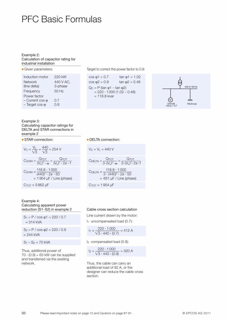
86 © EPCOS AG 2011Please read Important notes on page 12 and Cautions on page 87-91.
PFC Basic Formulas
Example 4: Calculating apparent power reduction (S1–S2) in example 2
S1 – S2 = 70 kVA
Thus, additional power of 70 · (0.9) = 63 kW can be suppliedand transferred via the existing network.
Cable cross section calculation
Line current drawn by the motor:
I1 uncompensated load (0.7):
220 · 1 000I1 = ––––––––––––––––– = 412 A��3 · 440 · (0.7)
I2 compensated load (0.9):
220 · 1 000I2 = ––––––––––––––––– = 320 A��3 · 440 · (0.9)
Thus, the cable can carry an additional load of 92 A, or the designer can reduce the cable crosssection.
S2 = P / cos ϕ2 = 220 / 0.9= 244 kVA
S1 = P / cos ϕ1 = 220 / 0.7= 314 kVA
Example 3: Calculating capacitor ratings forDELTA and STAR connections inexample 2
� STAR connection: � DELTA connection:
VC = VL = 440 V
QTOT QTOTCDELTA = –––––––––– = ––––––––––––––3 · (VL)2 · � 3 · (VL)2 · 2� · f
118.8 · 1 000CDELTA = –––––––––––––––––––––3 · (440)2 · 2� · 50
= 651 µF / Line (phase)
CTOT = 1 954 µF
VL 440VC = –––– = –––– = 254 V��3 ��3
QTOT QTOTCSTAR = ––––––––– = –––––––––––––(VL)2 · � (VL)2 · 2� · f
118.8 · 1 000CSTAR = –––––––––––––––––(440)2 · 2� · 50
= 1 954 µF / Line (phase)
CTOT = 5 862 µF
Example 2: Calculation of capacitor rating forindustrial installation
� Given parameters: Target to correct the power factor to 0.9:
Induction motor 220 kWNetwork 440 V AC, (line delta) 3-phaseFrequency 50 HzPower factor– Current cos ϕ 0.7– Target cos ϕ 0.9 118.8 kvar
440 V/ 50 Hz
M
220 kWcos ϕ = 0.7
cos ϕ1 = 0.7 tan ϕ1 = 1.02cos ϕ2 = 0.9 tan ϕ2 = 0.48
QC = P (tan ϕ1 – tan ϕ2) = 220 · 1000 (1.02 – 0.48) = 118.8 kvar
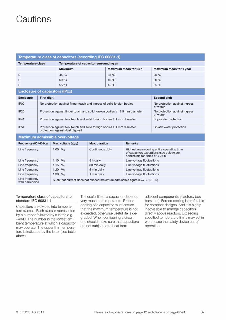
© EPCOS AG 2011 87Please read Important notes on page 12 and Cautions on page 87-91.
Cautions
Temperature class of capacitors tostandard IEC 60831-1
Capacitors are divided into tempera-ture classes. Each class is representedby a number followed by a letter, e.g.–40/D. The number is the lowest am-bient temperature at which a capacitormay operate. The upper limit tempera-ture is indicated by the letter (see tableabove).
The useful life of a capacitor dependsvery much on temperature. Propercooling of a capacitor must ensurethat the maximum temperature is notexceeded, other wise useful life is de-graded. When configuring a circuit,one should make sure that capacitorsare not subjected to heat from
adjacent components (reactors, busbars, etc). Forced cooling is preferablefor compact designs. And it is highlyinadvisable to arrange capacitors directly above reactors. Exceedingspecified temperature limits may set inworst case the safety device out ofoperation.
Enclosure First digit Second digit
IP00 No protection against finger touch and ingress of solid foreign bodies No protection against ingressof water
IP20 Protection against finger touch and solid foreign bodies ≥ 12.5 mm diameter No protection against ingressof water
IP41 Protection against tool touch and solid foreign bodies ≥ 1 mm diameter Drip-water protection
IP54 Protection against tool touch and solid foreign bodies ≥ 1 mm diameter, Splash water protectionprotection against dust deposit
Temperature class of capacitors (according IEC 60831-1)
Enclosure of capacitors (IPxx)
Frequency (50 / 60 Hz) Max. voltage (Vrms) Max. duration Remarks
Line frequency 1.00 · VR Continuous duty Highest mean during entire operating time of capacitor; exceptions (see below) are admissible for times of < 24 h
Line frequency 1.10 · VR 8 h daily Line voltage fluctuations
Line frequency 1.15 · VR 30 min daily Line voltage fluctuations
Line frequency 1.20 · VR 5 min daily Line voltage fluctuations
Line frequency 1.30 · VR 1 min daily Line voltage fluctuations
Line frequency Such that current does not exceed maximum admissible figure (Imax. = 1.3 · IR)with harmonics
Maximum admissible overvoltage
Temperature class Temperature of capacitor surrounding air
Maximum Maximum mean for 24 h Maximum mean for 1 year
B 45 °C 35 °C 25 °C
C 50 °C 40 °C 30 °C
D 55 °C 45 °C 35 °C
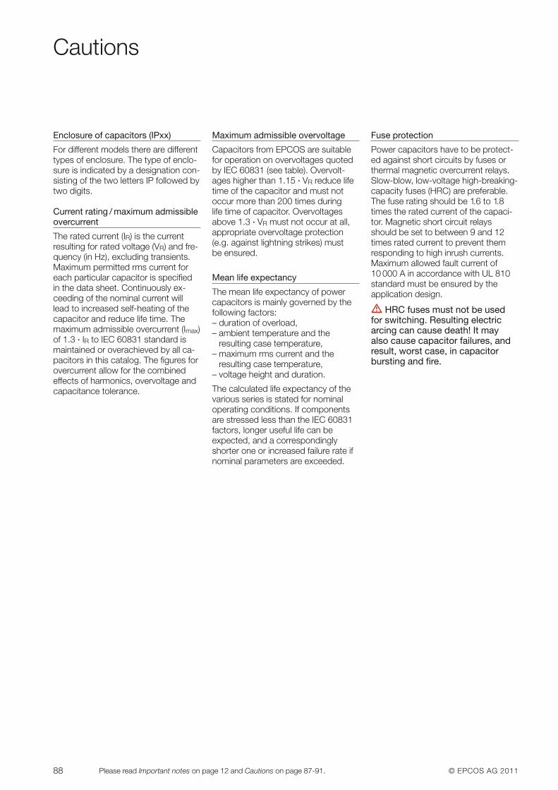
88 © EPCOS AG 2011Please read Important notes on page 12 and Cautions on page 87-91.
Cautions
Enclosure of capacitors (IPxx)
For different models there are differenttypes of enclosure. The type of enclo-sure is indicated by a designation con-sisting of the two letters IP followed bytwo digits.
Current rating / maximum admissible overcurrent
The rated current (IR) is the current resulting for rated voltage (VR) and fre-quency (in Hz), excluding transients.Maximum permitted rms current foreach particular capacitor is spe ci fiedin the data sheet. Continuously ex-ceeding of the nominal current willlead to increased self-heating of thecapacitor and reduce life time. Themaxi mum admissible overcurrent (Imax)of 1.3 · IR to IEC 60831 standard is maintained or overachieved by all ca-pacitors in this catalog. The figures forover current allow for the combined effects of harmonics, over voltage andcapa citance tolerance.
Maximum admissible overvoltage
Capacitors from EPCOS are suitablefor operation on overvoltages quotedby IEC 60831 (see table). Overvolt-ages higher than 1.15 · VR reduce lifetime of the capacitor and must not occur more than 200 times during life time of capacitor. Overvoltagesabove 1.3 · VR must not occur at all,appropriate overvoltage protection(e.g. against lightning strikes) must be ensured.
Mean life expectancy
The mean life expectancy of powercapacitors is mainly governed by the following factors:– duration of overload,– ambient temperature and the
re sulting case temperature,– maximum rms current and the
resulting case temperature,– voltage height and duration.
The calculated life expectancy of the various series is stated for nominal operating conditions. If componentsare stressed less than the IEC 60831factors, longer useful life can be expected, and a correspondinglyshorter one or increased failure rate ifnominal parameters are exceeded.
Fuse protection
Power capacitors have to be protect-ed against short circuits by fuses orthermal magnetic overcurrent relays.Slow-blow, low- voltage high-breaking-capacity fuses (HRC) are preferable.The fuse rating should be 1.6 to 1.8times the rated current of the capaci-tor. Magnetic short circuit relaysshould be set to between 9 and 12times rated current to prevent themresponding to high inrush currents.Maximum allowed fault current of10 000 A in accordance with UL 810standard must be ensured by the application design.
V HRC fuses must not be usedfor switching. Resulting electricarcing can cause death! It may also cause capacitor failures, andresult, worst case, in capacitorbursting and fire.
© EPCOS AG 2011 89Please read Important notes on page 12 and Cautions on page 87-91.
Cautions
Switching of capacitors
When a capacitor is switched to anAC system, the result is a resonant circuit damped to a greater or lesserdegree. In addition to the rated cur-rent, the capacitor accepts a transientcurrent that is a multiple of (up to 200times) its rated current. Fast switching,low-bounce contactors should beused, and have the switching capacityfor capacitive currents stated by theproducer. Special capacitor contac-tors with leading contacts that featureprecharging resistors to damp inrushcurrents are recommended. As perIEC 60831 standard, a maximum of5 000 switching operations per year is acceptable. Before considering ahigher number of switching opera-tions, please contact EPCOS.
Discharging
Capacitors must be discharged to amaximum of 10% of rated voltage be-fore they are switched in again. Thisprevents an electric impulse dischargein the application, influences the ca-pacitor’s useful life in PFC systems,and protects against electric shock.The capacitor must be discharged to75 V or less within 3 min. There mustnot be any switch, fuse or any other disconnecting device in the circuit be-tween the power capacitor and thedischarging device. EPCOS suppliescapacitor dis charge re sis tors to all se-ries, alternatively discharge reactorsare available.
V Caution: Discharge and shortcircuit capacitor before handling!
Capacitors in networks with har monics
Harmonics are produced in the opera-tion of electric loads with a non linearvoltage / current characteristic (e.g.rectifiers and inverters for drives, weld-ing apparatus and uninterruptiblepower supplies). Harmonics are sinu-soidal voltages and currents with high-er frequencies of a multiple of the 50or 60 Hz line frequency. In low- voltagethree-phase systems the 5th and 7thharmonics are especially troublesome.Detuned PFC should be used in sys-tems subject to harmonics. This repre-sents a series resonant circuit of pow-er capacitor and reactor. The circuit istuned so that the series resonant fre-quency is below the lowest harmonics
appearing in the system. This pro-duces an inductive response to all fre-quencies above the series resonantfrequency, avoiding resonances withsystem inductances. Depending onthe selected series resonant frequen-cy, part of the harmonic current is tak-en up by the detuned PFC system.The remainder of the harmonic currentflows into the superordinate system.The use of detuned PFC thus con-tributes to reducing voltage distortionthrough harmonics and lessens thedisturbing effect on proper operationof other electric loads.
Most international standards limitTHD-V on LV side to 5%. However ithas to be noted that in many gridsthese levels are exceeded and evenlower distortion, e.g. 3–4% THD-V cangenerate extreme overcurrents in caseof resonance condition.
Maximum overcurrents as specifiedunder technical data of each seriesmust not be exceeded.
Resonance must be avoided by ap-propriate panel design. Resonancemay cause very high overcurrentswhich can lead to capacitor failures,and worst case, to explosion and fire.
90 © EPCOS AG 2011Please read Important notes on page 12 and Cautions on page 87-91.
Cautions
Installation
Specifications like IEC 61921,VDE 0100, VDE 0101, VDE 0560 part4 and 46, EN 60831 and IEC 60831apply to the installation and operationof power capacitors. Capacitorsshould be sited in cool and well venti-lated locations away from other heat-radiating elements. Natural heat dissi-pation is generally sufficient for coolingpurposes if enough air is able to flowto and away from them and the ca-pacitors are spaced at least 20 mm
apart. Otherwise, in a less well venti-lated environment, forced cooling(fans) will be necessary, scaled so thatthe maximum admissible ambienttemperature is not exceeded.
Useful life of capacitors strongly de-pends on the operating tempera ture(refer to page 87, temperature classesof capacitors).
Exceeding maximum allowed temper-ature may set the safety device out ofoperation.
Please read the Installation and Main-tenance Instructions on the internet atwww.epcos.com/pfc.
Note
Products shown in this catalog reflecttypical specifications. You are kindlyrequested to approve our productspecifications or request our approvalfor your specification before ordering.
Mechanical damage
In case of dents or any other mechanical damage, capacitors must not be used at all.
Vibration resistance
The resistance to vibration of capacitors corresponds to IEC 68, part 2–6.
Max. test conditions:
Test duration 2 h
Frequency range 10 ... 55 Hz correspondingto max. 0.7 g
Displacement 0.75 mmamplitude
Because the fixing and the terminals may influence the vibration properties, it is necessary to check stability whena capacitor is built in and exposed to vibration.Irrespective of this, you are advised not to locate capaci-tors where vibration amplitude reaches the maximum instrongly vibrating equipment.
Connection
Make sure connection cables are of flexible type or flexiblecopper bands are used. This is mandatory to allow theoverpressure disconnector work and avoid mechanicalstress on the terminals and feedthroughs.
The connection cables to the capacitor should be de-signed for a current of at least 1.5 times the rated currentso that no heat is conducted into the capacitor. If reactorsare used in an application, the distance between reactorand capacitor must be great enough so that no heat ofthe reactors, which are operating at a much higher tem-perature level, is conducted via connection cable to thecapacitors.
Avoid bending cable lugs, cables or other mechanicalforce on the terminals. Otherwise leakages may set thesafety device out of operation.
Ensure firm fixing of terminals, fixing torque to be appliedas per individual specification.
Maximum specified terminal current (please refer to technical data of specific series) must not be exceeded atany case.
Grounding
The threaded bottom stud of the capacitor has to be used for grounding. In case grounding is done via metalchassis that the capacitor is mounted to, the layer of varnish beneath the washer and nut should be removed.
Storage and operating conditions
Do not use or store capacitors in corrosive atmosphere,especially where chloride gas, sulfide gas, acid, alkali, saltor the like are present. In dusty environments regularmaintenance and cleaning especially of the terminals is re-quired to avoid conductive path between phases and / orphases and ground.
© EPCOS AG 2011 91Please read Important notes on page 12 and Cautions on page 87-91.
Cautions
Reactors – Antiresonance harmonic filter
During operation, all electrically activeparts of this equipment such as wind-ings, electronic components, leads,fuses and terminals carry a dangerousvoltage which can lead to burns orelectric shock.
Covers which protect these electri callyactive parts from being touched mustnot be opened or removed during operation.
Before any assembly or maintenancework is started, all installations andequipment must be disconnectedfrom the power source.
In order to exclude impermissible tem-peratures and thus overload of the insulation system, the following direc-tions must additionally be observed:
1. Only those protective devicesspeci fied on the type plates, suchas fuses and motor protectionswitches, may be used. It is manda-tory to observe the set values specified for the motor protectionswitches. Any temperature-sensitiveprotective devices such as temper-ature switches and temperaturesensors must be connected in accordance with the installation instructions.
2. High temperatures are permissiblefor the surfaces under rated operat-ing conditions, and especially in theevent of overload. Depending onthe temper ature class and type ofloading, these may attain values ofup to 260 °C and may also affectadjacent components which havebeen packed too densely.
Noncompliance with these in struc -tions may lead to death, serious in -jury or major damage to equipment.
3. The insertion position should be selected so that any cooling ductspresent within the winding arearranged vertically and that the cur-rent of cooling air is not im peded byadjacent components, connectingleads etc.
4. The maximum voltage of the insu-lating system specified on the typeplate must not be exceeded.
Noncompliance with these in struc -tions may lead to consi derable damage to equipment or fire due toimpermissibly high temperatures.
Thyristor modules (TSM-series)
� Live parts in the PFC equipmentmust not be touched!
� Warning signs in the PFC systemsare required!
� Wait 10 minutes after the mainswitch is turned off – until the volt-age in the system has dropped to anuncritical value.
� In non-detuned systems (400 V grid)capacitors with a higher voltage rating (e.g. 440 V) are needed.
� In detuned systems (400 V grid) capacitors with a voltage of 525 Vare needed.
� For discharging the capacitors, special high-voltage resistors typeEW-22 are required. Standard resistors cannot be used!
� In dynamic PFC systems dischargereactors cannot be used (this wouldbe a short circuit of the highvoltageDC)!
� In PFC systems without filter circuitreactors current limiting reactors arerequired (e.g. BD-series) for theTSM.
� For short circuit protection, super -fast electronic fuses for protection ofthe thyristor are required, standardHRC fuses are not suitable. See se-lection table on pages 69 and 70.
� Failure to follow cautions may result,worst case, in premature failures orphysical injury.
Capacitor contactors
In case auxiliary contacts are used forswitching of discharge resistors (not inaccordance with IEC 60831 standard),make sure that the current of the dis-charge resistors is not higher than therated current of the auxiliary contacts.
Only flame-resistant and self-extin-guishing materials may be used in theproximity of capacitor contactors be-cause abnormal temperatures cannotbe ruled out in the area near the resis-tance spirals.
Capacitor contactors N110/N230 may only be used in PFC systems withreactors.
PF controllers (BR604, BR6000 and BR7000 series)
Controller hunting: When putting thecapacitor bank into operation, it is required to avoid needless switchingcycles (means permanent switchingon and off of steps without significantchange of consumer loads). This socalled “controller hunting” would increase the number of switching operations of the connected contac-tors and capacitors, decrease the expected life cycle (wear out) and result, in worst case, in bursting and fire etc. This can be avoided by a proper programming of the PF controllers with the actual systempara meters (current transformer prim.and sec., first kvar step, control series,switching time).
The “ZVEI General safety recom-mendations for power capacitors”must be observed in addition to the safety instructions given in thiscatalogue and in the particular data-sheets. They are available onthe EPCOS website in the variousproduct groups. They may also becalled up from the ZVEI website.
92 © EPCOS AG 2011
Get in Contact
AFRICAEgyptEgyelectronicsMaadi, CairoT +202 27 51 51 08T +201 68 82 88 20F +202 27 51 51 [email protected]
Maghreb: Morocco, Algeria,Lybia, Tunisia, MaltaEPCOS SASPANTINT +33 1 49 46 67 [email protected]
Republic of South AfricaElectrocomp (PTY) Ltd.SandtonT +27 11 458 90 00F +27 11 458 90 [email protected]
AMERICASNAFTAEPCOS, Inc.Iselin, NJ, USAT +1 732 9 06 43 [email protected]
South AmericaEPCOS do Brasil Ltda.São PauloT +55 11 36 12 51 87F +55 11 36 12 51 [email protected]
ArgentinaELECOND CAPACITORES S.A.Buenos AiresT +54 11 43 03 12 03F +54 11 43 03 12 [email protected]
BoliviaElectric Mundial S.R.L.T +59 13 33 32 90 [email protected]
SIEMENS S.A.Santa Cruz de la SierraT +591 3 31 10 011 ext.7013F +591 3 31 12 [email protected]
BrazilEPCOS do Brasil Ltda.São PauloT +55 11 36 12 51 87F +55 11 36 12 51 [email protected]
IFG ELECTROMECGravataíT +55 51 34 88 25 65F +55 51 34 31 38 [email protected]
RIONEPARRio de JaneiroT +55 21 38 99 35 33F +55 21 38 99 35 [email protected]
Siemens LTDASão PauloT +55 11 38 33 49 82F +55 11 38 33 48 [email protected]
WGR Indústria ComércioImportação e Exportação Ltda.São PauloT +55 11 21 55 55 29F +55 11 21 55 55 [email protected]
ChileCLAS INGENIERÍAELÉCTRICA S.A.Santiago de ChileT +562 6 22 52 12F +562 6 22 35 [email protected]
SIEMENS S.ASantiago de ChileT +562 4 77 13 07F: +562 4 77 10 [email protected]
ColombiaSIEMENS S.A.BogotáT +571 2 94 22 [email protected]
ESPECIALIDADESELÉCTRICAS S.A.CaliT +572 4 39 81 81F +572 4 46 44 [email protected]
Costa RicaSIEMENS S.A.San JoséT +506 2 87 51 [email protected]
EcuadorSIEMENS S.A.GuayaquilT +593 4 2 16 00 50 ext.4282F +593 4 2 16 00 50 [email protected]
El SalvadorSIEMENS S.A.San SalvadorT +503 2 78 33 [email protected]
GuatemalaSIEMENS S.A.Ciudad de GuatemalaT +502 3 79 23 32F +502 3 79 23 [email protected]
ParaguayLUMINOTECNIAAssunciónT +59 521 55 10 75F +59 521 55 12 [email protected]
PeruSIEMENS S.A.LimaT +511 2 15 00 30 ext. [email protected]
UruguayMGI S.A.MontevideoT +598 22 00 78 [email protected]
VenezuelaEMI – EQUIPOS Y SISTEMASCaracasT +582 12 2 43 60 79F +582 12 2 43 64 [email protected]
ASIABangladeshS.A. Traders & Co.DhakaT +880 2 955 83 40F +880 2 956 57 26
ChinaEPCOS (Shanghai) Ltd.XiamenT +86 592 22 02 22 10F +86 592 22 02 22 [email protected]
EPCOS (Shanghai) Ltd.BeijingT +86 10 85 86 86 73F +86 10 85 86 92 [email protected]
EPCOS (Shanghai) Ltd.ShenzhenT +86 755 82 75 91 00F +86 755 82 75 91 [email protected]
EPCOS (China) Investment Ltd.EPCOS (Shanghai) Ltd.Changning District, ShanghaiT +86 21 22 19 15 00F +86 21 22 19 15 [email protected]
EPCOS LIMITEDHong KongT +85 2 36 69 82 00F +85 2 36 69 82 [email protected]
IndiaEPCOS India Private Ltd.BengaluruT +91 80 40 39 06 08T +91 80 40 39 06 40F +91 80 40 39 06 [email protected]
EPCOS India Private Ltd.Mumbai, MaharashtraT +91 22 42 56 06 00F +91 22 26 83 26 45
EPCOS India Private Ltd.KolkataT/F +91 33 24198815
EPCOS India Private Ltd.New DelhiT +91 11 43 54 99 11/12F +91 11 23 70 41 46
IndonesiaPT Industrindo NiagatamaJakartaT +62 21 65 30 26 57F +62 21 65 30 26 [email protected] Ometraco Arya Samanta
JakartaT +62 21 619 61 66F +62 21 619 34 [email protected]
IranSaba Khazen Co.TehranT +98 21 88 88 90 13F +98 21 88 77 20 67
IsraelNisko Electricity& Electronics Ltd.Tel AvivT +972 37 65 71 00F +972 37 65 71 10
JapanEPCOS KKYokohamaT +81 45 4 78 72 00F +81 45 4 78 72 [email protected]
EPCOS KKOsakaT +81 6 62 92 69 11F +81 6 62 92 69 [email protected]
TDK-EPC CorporationTokyoT +81 3 52 01 72 41F +81 3 52 01 72 62Korea
EPCOS Korea LLCSeoulT +82 2 34 50 75 70F +82 2 34 50 75 [email protected]
MalaysiaAlpha Automation(Selangor) Sdn. Bhd.SelangorT +60 3 55 69 36 98F +60 3 55 69 40 [email protected]
© EPCOS AG 2011 93
Get in Contact
08/11
The addresses of our worldwide distributors and regional sales offices are available at www.epcos.com/sales
© EPCOS AG, Corporate Center, P.O.Box 80 17 09, 81617 Munich, Germany, T +49 89 636 09, F +49 89 636 226 89Reproduction, publication and dissemination of this publication and the information contained therein without EPCOS’ prior express consent is prohibited.
EPCOS RDC Sdn. Bhd.Kuala LumpurT +60 6 79 98 168F +60 6 79 98 [email protected]
NepalMachinery & Electric ComplexKathmanduT +97 71 423 25 44F +97 71 423 05 73
PhilippinesGTB Industrial Network IncManilaT +63 2 563 83 38F +63 2 563 25 [email protected]
Saudi ArabiaBahrainAdvanced ModularPower SystemsAl KhobarT +966 38 82 10 55F +966 38 87 68 64
SingaporeAsia Electric TechnologiesPte LtdSingaporeT +65 62 98 85 50F +65 62 99 60 [email protected]
Sri LankaK.I.K. Engineering Co. (Pvt) Ltd.Mount Lavinia,T +94 11 271 74 13 F +94 11 271 50 [email protected]
SyriaZAHABI CO.AleppoT +963 21 21 22 23 5/6F +963 21 21 22 23 [email protected]
TaiwanEPCOS Taiwan Co. Ltd.TaipeiT +886 2 26 55 76 76F +886 2 27 82 03 [email protected]
ThailandITM Capacitors Co. Ltd.Samut PrakamT +66 2 336 11 16F +66 2 336 11 [email protected]
United Arab EmiratesGama Electrical Trading CO. LLCSharjahT +971 65 33 54 53F +971 65 33 81 82
VietnamLTP Tech Co., LtdHo Chi Minh CityT +84 8 35 15 89 60F +84 8 35 15 89 [email protected]
AUSTRALIAElectric ComponentsSolutions Pty Ltd.Mulgrave, VIC 3170T +61 3 85 61 19 99F +61 3 95 74 70 [email protected]
EUROPEAustria, BulgariaEPCOS OHGVienna, AustriaT +43 51 70 72 56 30F +43 51 70 75 56 [email protected]
Benelux, FranceEPCOS SASPANTINT +33 1 49 46 67 [email protected]
CroatiaERG d.o.o.VaraždinT +385 42 35 17 77F +385 42 35 17 [email protected]
Czech RepublicEPCOS s.r.o.PragueT +420 2 33 03 22 81F +420 2 33 03 22 [email protected]
Estonia, FinlandEPCOS Nordic OYEspooT +358 95 480 7000F +358 95 480 [email protected]
Germany, Liechtenstein,SwitzerlandEPCOS AGCustomer Service, MünchenT (D) 0180 500 33 48
(0,12 Euro/Min.)T (CH) 08 48 37 26 71F +49 89 63 62 80 [email protected]
GreeceSiemens A.E.Amaroussio/AthensT +30 210 68 64 148F +30 210 68 64 562
HungaryEPCOS Kft.Értékesítési irodaBudapestT +36 1 436 07 20F +36 1 436 07 [email protected]
ItalyTDK-EPC Italy srlMilanoT +39 02 50 99 54 26F +39 02 50 99 54 [email protected]
Trendfin s.r.l.Limena (PD)T +39 049 88 48 011F +39 049 88 48 [email protected]
Poland, Latvia, LithuaniaEPCOS Poland Sp. z.o.o.Warsaw, PolandT +48 22 24 604 13F +48 22 24 604 [email protected]
Elgerta LTD(Elgerta Group Lithuania)Vilnius, LithuaniaT +370 5 265 26 83F +370 5 265 08 [email protected]
OLKO - Zakład Monta�uUrządzeń ElektronicznychGdańsk, PolandT +48 (58) 55 42 911F +48 (58) 55 43 [email protected]
Elhurt Sp. z o.o.Gdańsk, PolandT +48 58 554 08 00F +48 58 554 08 [email protected]
PortugalEPCOS 2 Portugal LDAÉvoraT +351 91 75 67 927F +351 21 49 33 [email protected]
RomaniaEPCOS Sales RepresentativeTimisoaraT +40 723 114 111F +40 356 416 [email protected]
EPCOS Sales RepresentativeBrasovT +40 724 58 84 94F +40 368 00 35 [email protected]
Russia, Belarus, Kazakhstan,Moldavia, UkraineEPCOS LLCKiev/MoscowT +7 495 663 21 41 (Moscow)T +380 44 362 54 26 (Kiev)[email protected]
SerbiaMK Trade d.o.o.BelgradeT +381 11 318 37 80F +381 11 227 46 [email protected]
Montprojekt d.o.o.BelgradeT +381 11 312 92 31F +381 11 312 91 [email protected]
SlovakiaEPCOS Sales AgencyDolny KubínT +42 1 43 5 82 36 73F +42 1 43 5 82 37 [email protected]
Slovenia, Croatia, Bosnia &Herzegovina, MontenegroEPCOS Sales RepresentativeŠkofljica, SloveniaT +386 59 95 63 53F +386 59 95 63 [email protected]
SpainEPCOS ELECTRONICCOMPONENTS S.A.Getafe (Madrid)T +34 91 514 80 00F +34 91 514 70 [email protected]
Sweden, Iceland,Denmark, NorwayEPCOS Nordic ABKista, SwedenT +46 8 4 77 27 00F +46 8 4 77 27 [email protected]
TurkeyEPCOS AGLiaison OfficeIstanbulT +90 216 5 69 81 00F +90 216 4 64 07 [email protected]
United Kingdom, IrelandEPCOS UK Ltd.BracknellT +44 13 44 38 15 10F +44 13 44 38 15 [email protected]


© EPCOS AG · A Member of TDK-EPC CorporationEdition 2011 · Ordering No. EPC:26035-7600 · Printed in Germany · PP 08115.