product overview po cc standard aluminium conveyor systems ... · pdf filestandard aluminium...
TRANSCRIPT

© FlexLink 2016 Standard aluminium conveyor systems 7
PO
CC
X45
XS
X65
X65P
X85
X85P
XH
XK
XKP
X180
X300
GR
CS
XT
WL
WK
XC
XF
XD
ELV
CTL
FST
TR
APX
IDX
Product overviewContentsStandard aluminium conveyor systems ................................7Stainless steel conveyor systems........................................11XT pallet system platform ...................................................12Conveyor accessories .........................................................12Conveyor comparison chart ................................................13Permitted load per link ........................................................13Typical standard conveyor components ..............................14
Conveyor component overview ...........................................15Structural systems XC/XF/XD..............................................18Structural systems component overview ............................19Technical data – conveyors .................................................21General safety and design considerations ...........................26Maintenance........................................................................28
Standard aluminium conveyor systems
Standard conveyors X45, X45H, XS, X65, X85, XH, XK, X180, X300Together, FlexLink's standard conveyor product lines cover a wide range of applications. These multiflexing conveyor sys-tems use plastic chains in many configurations. The chain design permits horizontal as well as ver-tical change of direction. Chain widths range from 43 mm up to 295 mm, for product widths up to 400 mm. Each system consists of a wide range of modular com-ponents which can be fitted using simple hand tools.
Pallet handling products (X65P, X85P, XKP)Catalogue sections X65P/X85P/XKP contain special products for pallet han-dling, including pallets, pallet locating stations, pallet stop cylinders and pal-let transfer stations. The systems are based on conveyor components from the standard conveyor lines.
The pallet handling system also includes divert/merge devices for easy trans-fer of pallets between conveyors.
Modular plastic belt conveyor WLThe Modular plastic belt conveyor is designed to trans-port bulky or soft, pliable, ready-packed products which call for the stable support of a wide chain.
The belt conveyor is suitable for applications that handle large cardboard boxes or products in soft plastic bags, such as detergent powder, wrapped tissue paper rolls, food products, personal care products and other large products.
Modular plastic belt conveyor WKThe modular belt conveyor is availa-ble in widths from 150-1200mm and is suitable for handling products from card board boxes to mechanical parts like bearings and sprocket wheels

8 Standard aluminium conveyor systems © FlexLink 2016
Conveyor system X45 (43 mm chain)
Conveyor system XS (44 mm chain)
Conveyor system X65/X65P (63 mm chain)
Conveyor system X85/X85P (83 mm chain)
Features
Very compact conveyor system for small and light items. Modular design concept for simplified engineering, fast config-uration and ordering.
The X45e drive unit and puck handling units offer unique possibilities for easy and efficient control of single piece flow sys-tem.
Examples of application areas
All types of small prod-ucts down to 10 mm diameter. Pharmaceuti-cal bottles and perfume bottles. Puck handling of products like test tubes for blood and urine, small bottles, cosmetics.
Conveyor System X45H (43 mm chain)
Chain permits transport of very small items which are otherwise difficult to handle. Compact and neat design. Can be seemless
Combined with X45 for puck handling systems. Have the advantage of longer length conveyors and higher speed than X45.
Features
Chain permits transport of very small items which are otherwise difficult to handle. Compact and neat design.
Examples of application areas
Small ball bearings, per-fume bottles, pharmaceuti-cal bottles, sintered metal components.
Features
Suitable for a wide range of applications. Preferable in high speed applications. Includes components for pal-let handling (X65P) and verti-cal wedge conveyors.
Examples of application areas
Tissue paper, gear wheels, aerosol cans, medium size ball bearings, piston parts, yoghurt, fuel injectors, dry batteries, plastic bottles, matches, cheese boxes, cof-fee and tea packages.
Features
Suitable for a wide range of applications. Includes compo-nents for pallet handling (X85P) and vertical wedge conveyors.
Examples of application areas
Ball valves, water meters, disk drives, pie packages, plastic bottles, beverage cans, products on pallets, paint cans, socks.
© FlexLink 2016 Standard aluminium conveyor systems 9
PO
CC
X45
XS
X65
X65P
X85
X85P
XH
XK
XKP
X180
X300
GR
CS
XT
WL
WK
XC
XF
XD
ELV
CTL
FST
TR
APX
IDX
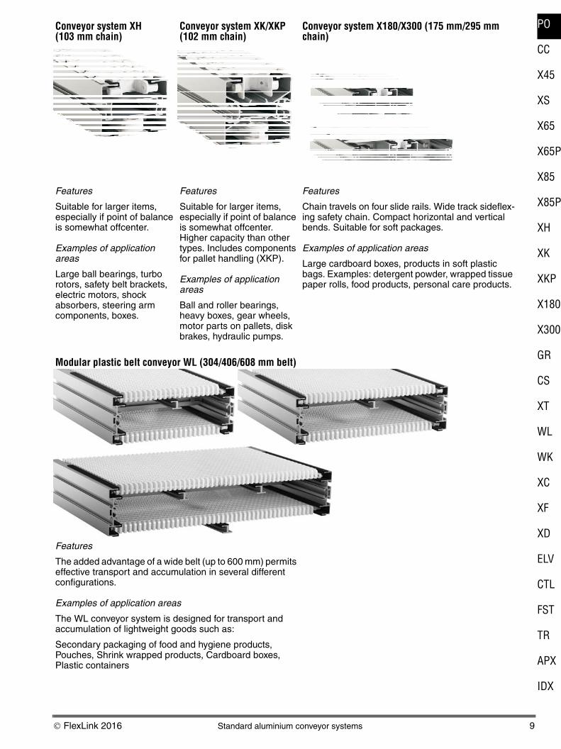
Conveyor system XH (103 mm chain)
Conveyor system XK/XKP (102 mm chain)
Conveyor system X180/X300 (175 mm/295 mm chain)
Features
Suitable for larger items, especially if point of balance is somewhat offcenter.
Examples of application areas
Large ball bearings, turbo rotors, safety belt brackets, electric motors, shock absorbers, steering arm components, boxes.
Features
Suitable for larger items, especially if point of balance is somewhat offcenter. Higher capacity than other types. Includes components for pallet handling (XKP).
Examples of application areas
Ball and roller bearings, heavy boxes, gear wheels, motor parts on pallets, disk brakes, hydraulic pumps.
Features
Chain travels on four slide rails. Wide track sideflex-ing safety chain. Compact horizontal and vertical bends. Suitable for soft packages.
Examples of application areas
Large cardboard boxes, products in soft plastic bags. Examples: detergent powder, wrapped tissue paper rolls, food products, personal care products.
Modular plastic belt conveyor WL (304/406/608 mm belt)
Features
The added advantage of a wide belt (up to 600 mm) permits effective transport and accumulation in several different configurations.
Examples of application areas
The WL conveyor system is designed for transport and accumulation of lightweight goods such as:
Secondary packaging of food and hygiene products, Pouches, Shrink wrapped products, Cardboard boxes, Plastic containers

10 Standard aluminium conveyor systems © FlexLink 2016
Modular plastic belt conveyor WK (150/225/300/600/900/1200 mm belt)
Features
The added advantage of a wide belt (up to 1200 mm) per-mits effective transport and accumulation in several differ-ent configurations.
Examples of application areas
The WK conveyor system is designed for transport and accumulation of lightweight goods such as:
Secondary packaging of food and hygiene products, Pouches, Shrink wrapped products, Cardboard boxes, Plastic containers

© FlexLink 2016 Stainless steel conveyor systems 11
PO
CC
X45
XS
X65
X65P
X85
X85P
XH
XK
XKP
X180
X300
GR
CS
XT
WL
WK
XC
XF
XD
ELV
CTL
FST
TR
APX
IDX
Stainless steel conveyor systems
(See Flexlink’s Product catalogue - Stainless 5693)
Stainless steel conveyor system XLX (63 mm chain)
Stainless steel conveyor system X85X, X180X, X300X (83, 175, 295 mm chain)
Features
Split beams in stainless steel for easy cleaning. High resistance to aggressive chemicals. Matching drive units, idlers and guide rail and support components.
Features
XLX conveyors are stainless steel designs adapted to the requirements of the food processing, pharmaceutical and hygiene industries. The Series X system is designed for easy integration with aluminium systems.
Examples of application areas
Aerosol cans, liquid soap in plastic bags, soft cheese, detergent powder, tissue paper rolls, food products, per-sonal care products.
Features
Split beams in stainless steel for easy cleaning. High resistance to aggressive chemicals. Matching drive units, idlers and guide rail and support components. Standard X180/X300 chains.
Series X are stainless steel designs adapted to the requirements of the food processing, pharmaceutical and hygiene industries. The Series X system is designed for easy integration with aluminium systems.
Examples of application areas
Aerosol cans, liquid soap in plastic bags, soft cheese, detergent powder, tissue paper rolls, food products, per-sonal care products.
Stainless steel conveyor system WLX 374, WLX 526 WLX 678 (304, 456, 608 mm belt)
Features
FlexLink's newly developed stainless steel conveyor is designed to fit into demanding primary and secondary pack-aging applications. It addresses important aspects of today's packing processes, such as being easy to clean, smooth handling of products, safe for operators, robust design, long life, and easy to maintain with a low cost of own-ership.
The modularized and standardized design ensures fast set up, and facilitates rapid future extensions and changes.Examples of application areas
Primary and secondary packed food and personal products
Wash down environments and heavy dust zone (vacuum)

12 XT pallet system platform © FlexLink 2016
XT pallet system platform Conveyor accessories
Guide rail components (GR)
Catalogue section Guide rail components deals with var-ious types of guide rails and guide rail support compo-nents. Those products are used with several of the con-veyor systems. A number of pre-designed guide rail structures are shown as examples. New components are available for building automatically adjustable guide rail systems, accommodating products with different widths.
Conveyor support components (CS)
The conveyors are held in place by a well balanced range of support components, with beam support brackets, support beams, feet, etc.
A number of pre-designed support structures are shown as examples.
Conveyor structures built from aluminium beams with standardized T-slots simplify attachment of components and accessories.
Twin-track pallet conveyor system XTC and XT Features
Twin-track flexible plas-tic chain pallet con-veyor system.
Pallet conveyor system XT is well suited for manual and automatic assembly and test systems in the automotive and electrical/electronics industries. It can handle square and rectangular pallets from 240 mm × 240 mm up to 640 mm × 640 mm.
Examples of application areas
Manual and automatic assembly and test systems in the automotive and electrical/electronics industries. Exam-ples: assembly and transport of receivers, computers, gear boxes, medical equipment, sewing machines, cell phones, housings, pumps, and air filters.

© FlexLink 2016 Conveyor comparison chart 13
PO
CC
X45
XS
X65
X65P
X85
X85P
XH
XK
XKP
X180
X300
GR
CS
XT
WL
WK
XC
XF
XD
ELV
CTL
FST
TR
APX
IDX
Conveyor comparison chart
Simplified end views of conveyor beams, drawn to the same relative scale. Numeric values are widths in mm.
Permitted load per link
X180175
X300295
XK102
XH103
X85X83
X85Y83
X8583
XLX63
X6563
XS44
XK102
200250300
160
X8583
43XT
XT 240
XT 640
XT 480
XT 400
XT 320X4543
X4543
100
X6563
X300X295
X180X175
Modular Plastic Belt Conveyor WL Modular Plastic Belt Conveyor WK
WK 150
WK 225
WK 300
WK 600
WK 900
WK 1200
WL526X
WL374X
WL678X
WL 424
WL 322
WL 626
Modular Plastic Belt Conveyor WLX
Legend
Light grey: Conveyor beams
Dark grey: Pallets or puck
White: Chain/Belt
XLX, X85X, X180X, X300X: WL374X, WL526X, WL678X
Stainless steel conveyor
Conveyor platform Chain width, mm Maximal permitted load per link/ Kg
X45 43 0,1
XS 44 0,5
X45H 44 1
XTC 35 0,5
XT 35 1
X65 63 1,5
X85 83 2,5
XH 103 2
XK 103 5
X180 175 2,5
X300 295 2,5
WL 322 304 2
WL 424 406 2
WL 626 608 2
WK 150 145 5
WK 225 220 5
WK 300 299 5
WK 600 597 5
WK 900 896 5
WK 1200 1195 5

14 Typical standard conveyor components © FlexLink 2016
Typical standard conveyor components
Feet and support beams Beam support brackets Conveyor beams and bends
Drive units Idlers Slide rail
Conveyor chain Guide rail brackets Guide rails
Drip trays and drip pans

© FlexLink 2016 Conveyor component overview 15
PO
CC
X45
XS
X65
X65P
X85
X85P
XH
XK
XKP
X180
X300
GR
CS
XT
WL
WK
XC
XF
XD
ELV
CTL
FST
TR
APX
IDX
Conveyor component overview
Conveyor support products (support beams, feet, etc.) are presented in catalogue section Conveyor support components (CS). For additional beam types, connec-tors, etc., see Structural system XC/XD/XF (page 18).
A range of pre-engineered support solutions are availa-ble. Please contact FlexLink for more information.
Chain products X45, X45H, XTC, XT, XS, X65, X85, XH, XKPlain chain Steel top chain Friction top chain Universal chain
Cleated chain Type A Cleated chain Type B Cleated chain Type C Cleated chain Type D
Cleated chain Type G Flexible cleat chain Type B Flexible cleat chain Type C Flexible cleat chain Type D
Roller top chain Roller cleat chain Steel chain
Chain products X180/X300 Conveyor beam X180/X300Plain chain Friction top chain Roller cleat link Conveyor beam section
Drive units and idlers X180/X300 Bends X180/X300End drive units Idler end unit Plain bends Vertical bends
Conveyor beams X45, X45H, XTC, XT, XS, X65, X85, XH, XKStandard Reinforced (XH only) XK, standard XK, Type N
Conveyor beam support brackets X45, X45H, XTC, XT, XS, X65, X85, XH, XK, X180/X300Type CT, aluminium Type CS, aluminium Type CS, polyamide Type CU, aluminium

16 Conveyor component overview © FlexLink 2016
Conveyor component overview (continued)
Drive units and idler units X45, XTC, XT, XS, X65, X85, XH, XKX45 End drive unit 24V End drive units End drive units, direct drive End drive units, double
X45 End drive unit 400V Intermediate drive units Catenary drive units Bend drive units
X45 Idler end Synchronous drive units End drive units Idler units
Wheel bends XT, XS, X65, X85, XH, XK
Bends X45, XTC, XS, X65, X85, XH, XK
Wheel bends Plain bends Vertical bends
Accessories XS, X65, X85, XH, XKAngle plates Angle plates for bends Front piece
Drip trays Drip pans for wheel bends Drip pans for vertical bends

© FlexLink 2016 Conveyor component overview 17
PO
CC
X45
XS
X65
X65P
X85
X85P
XH
XK
XKP
X180
X300
GR
CS
XT
WL
WK
XC
XF
XD
ELV
CTL
FST
TR
APX
IDX
Guidance X45, XS, X65, X85, XH, XK, X180/X300Guide rail profiles Flexible roller guide rail Guide discs (not
X180/X300)Built-up guide rail brackets
Fixed guide rail brackets, aluminium
Fixed guide rail brackets, polyamide
Adjustable guide rail brack-ets, aluminium
Adjustable guide rail brack-ets, polyamide
Pallet handling components XT, XTC, X65, X85, XKProduct carriers (pallets) Guide rails for bend Pallet stop device
Pallet locating station Diverting and merging modules X85/XK Locating modules X85
Diverter kits Merge kits Combined divert-merge kits

18 Structural systems XC/XF/XD © FlexLink 2016
Structural systems XC/XF/XD
Features • A wide range of modular extruded aluminium beams
with uniform T-slots.
• Standard component assortment for every application area.
• Easy to assemble, adjust, and dismantle using simple hand tools.
• Short time from concept to finished design.
• No welding or painting necessary.
Examples of application areas
Frameworks, workbenches, enclosures, special machin-ery, pick-and-place units, gantry robots
XC – heavier frameworks and machine stands
Structural system XC is based on the module 44 mm and offers sturdy components which provide high load capac-ity for both static and linear motion systems. It is used within a wide range of applications, from frameworks, work benches and enclosures to special machinery, pick and place units and gantry robots.
XF – compact and light enclosure applications
Structural system XF is based on the module 30 mm. It consists of a range of standard components, with emphasis on enclosure applications.
XD – compact and light automation applications
Structural system XD is based on the module 22 mm. The system focuses on compact, light automation appli-cations. It consist of a comprehensive range of standard components and ready-made functional units for linear and rotary motion.
44/88/132/176
44
44/88
11
30
30/60
30
7
22
22
© FlexLink 2016 Structural systems component overview 19
PO
CC
X45
XS
X65
X65P
X85
X85P
XH
XK
XKP
X180
X300
GR
CS
XT
WL
WK
XC
XF
XD
ELV
CTL
FST
TR
APX
IDX
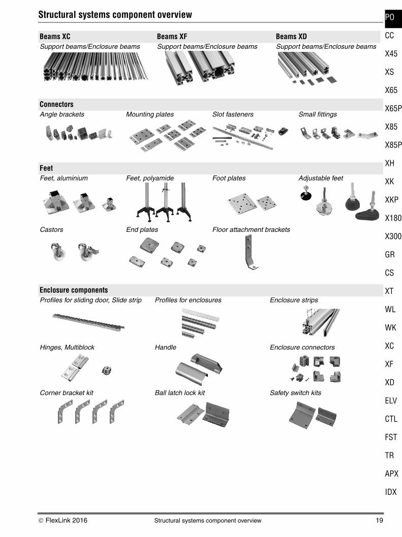
Structural systems component overview
Beams XC Beams XF Beams XDSupport beams/Enclosure beams Support beams/Enclosure beams Support beams/Enclosure beams
ConnectorsAngle brackets Mounting plates Slot fasteners Small fittings
FeetFeet, aluminium Feet, polyamide Foot plates Adjustable feet
Castors End plates Floor attachment brackets
Enclosure componentsProfiles for sliding door, Slide strip Profiles for enclosures Enclosure strips
Hinges, Multiblock Handle Enclosure connectors
Corner bracket kit Ball latch lock kit Safety switch kits

20 Structural systems component overview © FlexLink 2016
Structural systems component overview (continued)
Components for linear motion and rotating motionSliding element for T-slot Sliding elements for guide profile Wheels, Wheel yoke
Roller units for linear beams Joint, Extruded joint
Conduit elementsCable duct Cable duct with divider L-connection 45º and 90º and T-connection

© FlexLink 2016 Technical data – conveyors 21
PO
CC
X45
XS
X65
X65P
X85
X85P
XH
XK
XKP
X180
X300
GR
CS
XT
WL
WK
XC
XF
XD
ELV
CTL
FST
TR
APX
IDX
Technical data – conveyors
Drive unit capacityThe required motor output power P depends on
• Traction force F
• Chain speed v
The following equation applies:
The maximum permissible traction force of the various drive units, and other useful parameters, are shown in the following tables. Also see diagrams on page 22.
More informationDetailed information about the drive units can be found in “Drive unit guide” and “Spare parts”. See “Technical library” on FlexLink´s website. For information about drive units with variable speed motors, see Drive Unit Guide.
Drive unit specificationsEnd drive unit
Double drive unit
Intermediate drive unit
Catenary drive unit
Bend drive unit
Direct drive unit for wedge conveyor
See “End drive units”, above.
Synchronous drive unit for wedge conveyor
End drive unit WL
Number of teeth on sprocket wheel ... 2×16
Number of sprocket wheels vs. conveyor width
TemperaturesWhat temperatures can a FlexLink conveyor operate in?
A FlexLink conveyor can operate in temperatures between –20 °C and +60 °C.
Temperatures up to +100 °C can be taken for short peri-ods. This is mainly for cleaning and rinsing.
What happens if these limits are exceeded?
In cases where the recommended specifications have not been followed, such as in very warm and cold condi-tions, this will change the properties of the materials used.
FlexLink cannot guarantee components and their func-tionality in case these recommendations are not fol-lowed.
P [W] = 1/60 × F [N] × v [m/min]
X45H XS X65 X85 XH XK X180/X300
Number of teeth on sprocket wheel
16 16 C: 11M: 11H: 16
C: 9M: 9H: 12
12 11 12
Chain pitch (mm) 25,4 25,4 25,4 33,5 35,5 38,1 33,5
Maximum traction force (N)Type CN_PType MN_P Type H, H_P, HN_PStandard 900
500
300700
1000
300800
1250 1250 25001250
1250
XS X65 X85 XH XK
Number of teeth on drive wheel 16 16 12 12 11
Chain pitch (mm) 25,4 25,4 33,5 35,5 38,1
Maximum traction force (N) 500 1000 1250 1250 1250
c/c distance between the two lanes (mm)
55 or 90–350
66 or 110–350
86 or 130–350
106 or 150–350
106 or 150–350
X65 Medium
X65 Heavy
X85 X85 Heavy
XH
Number of teeth on drive wheel
11 16 9 9 9
Chain pitch (mm) 25,4 25,4 33,5 33,5 35,5
Maximum traction force (N) 200 700 200 875 200
XH XK
Number of teeth on drive wheel 12 11
Chain pitch (mm) 35,5 38,1
Maximum traction force (N) Type H Standard
1250 25001250
XS X65 X85 XH XK
Pitch diameter (mm) 300 300 320 340 400
Maximum traction force (N) 200 200 200 200 200
X65 X85
Number of teeth on drive wheel 16 12
Chain pitch (mm) 25,4 33,5
Width 322 mm 424 mm 626 mm
Sprocket wheels 5 5 7
Belt pitch (mm) 25,4 mm

22 Technical data – conveyors © FlexLink 2016
Technical data – conveyors (continued)
Chain tension limitsTo determine the maximum chain tension allowed, it is necessary to take conveyor speed and conveyor length into consideration. Check diagram 1A and 2B-2E and use the lowest tension value obtained.
Note!
The drive unit configurator on the web always proposes a motor strong enough to utilize the maximum permissible chain tension as specified in the diagrams below. Varia-ble speed motors at very low frequencies can sometimes drop below the specified tension. Always check motor data if high pulling force is critical.
Maximum permissible chain tension
Diagram 1A
Tension/length diagram
Diagram 2A
Tension/speed diagram, XS, X180/X300, XK conveyors
Diagram 2B
Tension/speed diagram, X65 Type C/M/H
Diagram 2C
Tension/speed diagram, X85 C/M/H
Diagram 2D
Tension/speed diagram, Bend drive units
Diagram 2E
Tension/speed diagram, X45 Drive units
5 10 15 20 25 30 35 4000
500
1000
1500
2000
2500
m
N
X85, X180/X300, XH
X65
X45H
XK
XS
Tension
Conveyor length
5 10 15 20 25 30 35 40 45 5000
500
1000
1500
2000
3000
2500
m/min
N
X180/X300, XK, XH
XS
XK H
60
Tension
Conveyor speed
0
200
400
600
800
1000
1200
10 20 30 40 50 60 80 100
m/min
N
70 90 1100 120
X65 H
X65 M
X65 C
Tension
Conveyor speed
0
200
400
600
800
1000
1200
1400
5 10 15 20 25 30 40 50
m/min
N
35 45 550 60
X85 H
X85 M
X85 C
65
Tension
Conveyor speed
0
200
400
5 10 15 20 25 30 m/min
N
0
XSEWXLEWXBEWXHEWXKEW
Speed
Tension
5 10 15 20 2500
50
100
150
30 m/min
N
200
250
End drive unit400 V
End drive unit 24 VIntermediate drive unit 24 VIntermediate drive unit 400 V
Conveyor speed
Tension
X45
© FlexLink 2016 Technical data – conveyors 23
PO
CC
X45
XS
X65
X65P
X85
X85P
XH
XK
XKP
X180
X300
GR
CS
XT
WL
WK
XC
XF
XD
ELV
CTL
FST
TR
APX
IDX
Technical data – conveyors (continued)
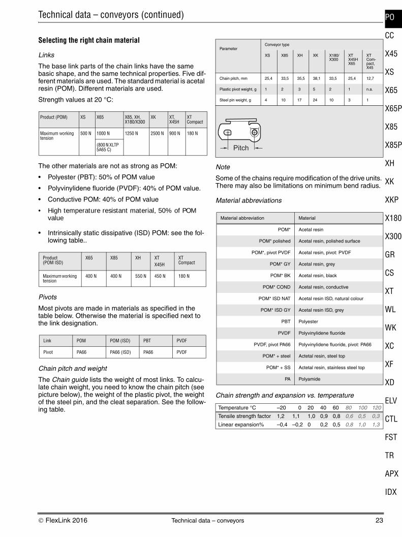
Selecting the right chain material
Links
The base link parts of the chain links have the same basic shape, and the same technical properties. Five dif-ferent materials are used. The standard material is acetal resin (POM). Different materials are used.
Strength values at 20 °C:
The other materials are not as strong as POM:
• Polyester (PBT): 50% of POM value
• Polyvinylidene fluoride (PVDF): 40% of POM value.
• Conductive POM: 40% of POM value
• High temperature resistant material, 50% of POM value
• Intrinsically static dissipative (ISD) POM: see the fol-lowing table..
Pivots
Most pivots are made in materials as specified in the table below. Otherwise the material is specified next to the link designation.
Chain pitch and weight
The Chain guide lists the weight of most links. To calcu-late chain weight, you need to know the chain pitch (see picture below), the weight of the plastic pivot, the weight of the steel pin, and the cleat separation. See the follow-ing table.
Note
Some of the chains require modification of the drive units. There may also be limitations on minimum bend radius.
Material abbreviations
Chain strength and expansion vs. temperature
Product (POM) XS X65 X85, XH, X180/X300
XK XT, X45H
XT Compact
Maximum working tension
500 N 1000 N 1250 N 2500 N 900 N 180 N
(800 N XLTP 5A65 C)
Product (POM ISD)
X65 X85 XH XT X45H
XT Compact
Maximum working tension
400 N 400 N 550 N 450 N 180 N
Link POM POM (ISD) PBT PVDF
Pivot PA66 PA66 (ISD) PA66 PVDF
ParameterConveyor type
XS X85 XH XK X180/X300
XTX45HX65
XT Com-pact, X45
Chain pitch, mm 25,4 33,5 35,5 38,1 33,5 25,4 12,7
Plastic pivot weight, g 1 2 3 5 2 1 n.a.
Steel pin weight, g 4 10 17 24 10 3 1
Material abbreviation Material
POM* Acetal resin
POM* polished Acetal resin, polished surface
POM*, pivot PVDF Acetal resin, pivot: PVDF
POM* GY Acetal resin, grey
POM* BK Acetal resin, black
POM* COND Acetal resin, conductive
POM* ISD NAT Acetal resin ISD, natural colour
POM* ISD GY Acetal resin ISD, grey
PBT Polyester
PVDF Polyvinylidene fluoride
PVDF, pivot PA66 Polyvinylidene fluoride, pivot: PA66
POM* + steel Actetal resin, steel top
POM* + SS Actetal resin, stainless steel top
PA Polyamide
Temperature °C –20 0 20 40 60 80 100 120
Tensile strength factor 1,2 1,1 1,0 0,9 0,8 0,6 0,5 0,3
Linear expansion% –0,4 –0,2 0 0,2 0,5 0,8 1,0 1,3
Pitch

24 Technical data – conveyors © FlexLink 2016
Service factorThe maximum permissible chain tension (see diagrams 1A and 2A-2E on Page 22) depends on the number of conveyor starts and stops per hour. Many conveyors run continuously, whereas others start and stop frequently. It is obvious that frequent starts and stops increase the stress on the chain.
The service factor (see table below) is used to derate for high frequency of starts and stops and for high chain speeds. Divide the tension limit obtained from the graphs by the service factor to get the derated tension limit. A high service factor can be reduced by providing a soft start/stop function.
ImportantThe chain tension calculations are made to ensure that the capacity of the drive unit is sufficient, but not exces-sive, in relation to the strength and friction of the chain. The calculations do not take into account the increased wear resulting from the higher friction in plain bends.
Chain tension calculations
Chain tensionThe tension building up in the chain can be divided into several components:
1 Friction between unloaded chain and slide rails, for example on the underside of the conveyor beam.
2 Friction between loaded chain and slide rails (Figure A).
3 Friction between accumulating products and top sur-face of chain (Figure B).
4 Gravity force acting on products and chain in inclines and verticals (Figure C).
5 Added friction in plain bends. This friction is propor-tional to the chain tension on the low-tension side of the bend. This means that the actual friction depends on the position of the bend in the conveyor (Figure D).
Traction forceThe traction force F required to move the chain depends on the following factors:
Conveyor length ........................................... LProduct gravity load per m Transport .................................................... qp Accumulation ............................................. qpaChain gravity load per m .............................. qcFriction coefficient Between chain and slide rail ...................... μr Between chain and products...................... μpBend factor, α° plain bend (hor./vert.) .......... kαInclination angle ........................................... β
Operating conditions Service factor
Low to moderate speed or max. 1 start/stop per hour
1,0
Max. 10 starts/stops per hour 1,2
Max. 30 starts/stops per hour 1,4
High speed, heavy load, or more than 30 starts/stops per hour
1,6
L
q +qc p
μr
F
F=L (qc+qp) r⋅ ⋅μ
Figure A
L
q +qc pa
μr
μp F
F=L [(qc+qpa) r+qpa p]⋅ ⋅μ ⋅μ
qpa
Figure B
L
q +qc p
μr
F
F=L (qc+qp) ( r cos +sin )⋅ ⋅ μ ⋅ β β
β
Figure C
F
L
L
FB
α
Figure D

© FlexLink 2016 Technical data – conveyors 25
PO
CC
X45
XS
X65
X65P
X85
X85P
XH
XK
XKP
X180
X300
GR
CS
XT
WL
WK
XC
XF
XD
ELV
CTL
FST
TR
APX
IDX
Bend factorsEach plain bend introduces a bend factor kα. This factor is defined as the ratio between chain tension measured just after the bend and that measured before the bend. The bend factor depends on
• the amount of direction change of the bend (angle α)
• the coefficient of friction, μr, for the friction between chain and slide rails.
When the conveyor is dry and clean, the friction coeffi-cient, μr, will be close to 0,1.
The bend factor must be used since the frictional force of a plain bend depends not only on the chain and prod-uct weight and the coefficient of friction, but also on the actual tension of the chain through the bend. This tension causes additional pressure to the conveyor beam and slide rail from the chain. The additional force is directed towards the centre of the bend.
Calculation of this additional force is more compli-cated, since the chain tension varies through the con-veyor, being maximum at the “pull” side of the drive unit, and virtually zero at the inlet of the return chain. The bend factor provides a means of including the added fric-tion in bends into the calculations.
The same bend factors apply to horizontal and verti-cal plain bends. See the table.
Note
Plain bends should only be used in exceptional cases. For normal applications, use wheel bends.
Bend type (Vertical or Plain bend)
30° 45° 60° 90°
Bend factor kα 1,2 1,3 1,4 1,6
26 General safety and design considerations © FlexLink 2016
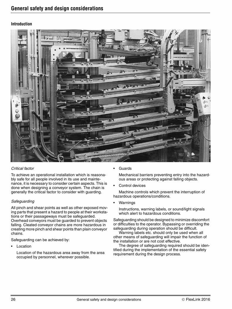
General safety and design considerations
Introduction
Critical factor
To achieve an operational installation which is reasona-bly safe for all people involved in its use and mainte-nance, it is necessary to consider certain aspects. This is done when designing a conveyor system. The chain is generally the critical factor to consider with guarding.
Safeguarding
All pinch and shear points as well as other exposed mov-ing parts that present a hazard to people at their worksta-tions or their passageways must be safeguarded. Overhead conveyors must be guarded to prevent objects falling. Cleated conveyor chains are more hazardous in creating more pinch and shear points than plain conveyor chains.
Safeguarding can be achieved by:
• Location
Location of the hazardous area away from the area occupied by personnel, wherever possible.
• Guards
Mechanical barriers preventing entry into the hazard-ous areas or protecting against falling objects.
• Control devices
Machine controls which prevent the interruption of hazardous operations/conditions.
• Warnings
Instructions, warning labels, or sound/light signals which alert to hazardous conditions.
Safeguarding should be designed to minimize discomfort or difficulties to the operator. Bypassing or overriding the safeguarding during operation should be difficult.
Warning labels etc. should only be used when all other means of safeguarding will impair the function of the installation or are not cost effective.
The degree of safeguarding required should be iden-tified during the implementation of the essential safety requirement during the design process.

© FlexLink 2016 General safety and design considerations 27
PO
CC
X45
XS
X65
X65P
X85
X85P
XH
XK
XKP
X180
X300
GR
CS
XT
WL
WK
XC
XF
XD
ELV
CTL
FST
TR
APX
IDX
General safety and design considerations (continued)
Special considerationsWhen correctly applied, FlexLink family of components are safe to use and maintain. It is however necessary for those responsible for design, installation, operation and maintenance of installations to be aware of certain areas where special attention is required.
All drive units with slip clutch
• Before adjusting the slip clutch it is necessary to remove all objects from the chain to remove any remaining chain tension.
• Adjustment should be conducted in accordance with the maintenance procedures.
• All drive units, except the direct drive units, are fitted with transmission chain covers, these covers must be fitted before unit is operated.
Note
The slip clutch is not a personnel safety device, but a device to protect the conveyor equipment.
End drive units
• The chain slack (catenary) of the end drive units must be maintained during the system lifetime.
• If side plates are fitted, the chain must be shortened if the chain becomes visible below the level of the side plates.
• The opening between the links when they turn round the end roller could be a risk. Drive ends should not be accessible during conveyor operation wherever possible.
For coupled drive units, safety protection should be applied to the connecting shaft.
Intermediate drive units
• The area near the guides for the return loop of the chain should not be accessible during conveyor oper-ation.
Catenary drive unit
• The ‘bridge’ area where the chain goes down into the drive should not be accessible during conveyor oper-ation.
Bend drive unit
• The drive wheel and the transmission chain should not be accessible during the conveyor operation.
Idler units
• The opening between the links when they turn round the idler roller could be a risk. Idler ends should not be accessible during conveyor operation wherever possi-ble.
Wheel bends
• Guarding may be required at wheel bends depending upon location of bends and load applied to the con-veyor.
Cleated chains
• Any application incorporating cleated chains requires careful safety consideration. Pinch and shear points are generated throughout the assembly of the incor-porated components. Therefore generous guarding should always be employed to fully protect within user operating limitations.
• There is a higher risk of product damage when using cleated chains. Special attention must be given to operator access in the event of products becoming trapped or similar.
Maintenance
The maintenance routine of FlexLink´s conveyors should also include procedures to ensure that the guarding remains securely fastened and effective (if not inter-locked via control system etc.).
FlexLink´s components are continuously reviewed to improve performance either by design modification or material upgrade. In all these reviews user safety is our primary consideration.
All associated technical data is retained at the manu-facturer's address.
Control system
Before operating or completing any maintenance on con-trol system, read the associated section as supplied with the equipment documentation.
If there are any questions as to the safe operating pro-cedures of the equipment supplied, please contact Flex-Link immediately.
28 Maintenance © FlexLink 2016
Maintenance
System maintenance
Introduction
The following section is designed to offer assistance for your planned maintenance schedule. It may become evi-dent that the suggested maintenance intervals can be extended to accommodate your local environmental con-ditions.
Maintenance of the conveyor systems should only be carried out by competent persons, who are familiar with FlexLink´s equipment. If there is any doubt as to the most suitable procedure for maintenance, consult your Flex-Link supplier.
Run-in periodTwo to three weeks is usually enough as a run-in period. During this time, the conveyor should be cleaned a cou-ple of times, to remove dust. After run-in, wear will be minimal, unless particles from the product or process reach the conveyor continuously.
Chain elongationEspecially during the run-in period, and if the load is heavy, the conveyor chain will slowly increase in length. This effect will be most obvious for long conveyors. After continuous operation for two weeks, it is often possible to remove a couple of chain links. After this period, we rec-ommend a check every 3–6 months.
Non FlexLink equipment
Equipment and components which are not from the Flex-Link family of products should be maintained and ser-viced in accordance with their respective manufacturer’s instructions.
Safety considerations
Before starting any maintenance on your FlexLink equip-ment, the following safety instructions must be observed:
• All electricity must be switched off.
• Make sure that the motor switch is also switched off and locked in the “off” position.
• Pneumatic and/or hydraulic power must be discon-nected and any pressure accumulation released.
• Products being transported should, if possible, be removed from the conveyor chain.
• Staff affected must be informed that maintenance work is being undertaken.
Warning
Do not climb onto the equipment.