product overview and comparison tables - welcome to …€¦ · honeywell‘s business unit...
TRANSCRIPT

Product overview and comparison tablesEasy selection of the right components
Cooling Components

2
Reliability and quality for professionals
Honeywell‘s business unit „Cooling Solutions“ is specialized in the development and production of high quality cooling components.
For our customers that means: a broad choice of many innovative and well established expansion valves, solenoid valves and filter driers as well as a good range of other cooling components.
In Mosbach, Germany product managers, the sales department, development engineers and the production are working close together focusing on the highest level of customer satisfaction through optimal products.
To achieve this goal, H.O.S., the Honeywell Operating System, was developed. H.O.S. stands for a big bundle of methods, princip-les and procedures which are de-fining operating standards and processes for all staff members.
Thereby we work extremely
•CUSTOMERORIENTED: We guarantee highest German and International quality standards as well as a fast delivery performance.
•FLEXIBLE: Through our modular system we are able to efficiently produce large numbers of customized variants.
•FAST: We also produce with minimal order quantities and short tooling times.
Components of the market leader in many areas
Put us on the test and start the comparison.
To facilitate this you can find com-plete comparative tables with products of different manufacturers on the following sites of this brochure.
Subjecttochangewithoutnotice·EN3H-0375GE23R0709

3
Content
Overview expansion valves .......................................................................4-5
Comparative tables expansion valves ..................................................6-13
Dimensionaldrawingsexpansionvalves .............................................14-17
Overview/Dimensionaldrawingssolenoidvalves ............................18-19
Comparative tables solenoid valves ......................................................20-21
Overview/Dimensionaldrawingssightglasses .................................22-23
Comparative tables sight glasses ...........................................................24-25
Overview/Dimensionaldrawingsfilterdrier .........................................26-27
Comparative tables filter drier ..................................................................28-29
Additionalcoolingcomponents ...............................................................30
Electroniccoolingcomponents ...............................................................31
Overview of types ..........................................................................................32
Online service ..................................................................................................33
Andbecauseweknowhowimportant fast and qualitative advices are especially when you need them the most we offer a direct line to our experienced specialists.
Here you get firsthand advices without long waiting times for your contact person.
Call us for questions at any time:
+49 6261 81- 475alternative per fax: +49626181-461
Subjecttochangewithoutnotice·EN3H-0375GE23R0709

4
Expansion valves
Expansion Valves are used to expand liquid refrigerant from a higher pressure and a higher temperature to a lower pressure andalowertemperature.Asacontrollerforsuperheat,Expan-sion Valves control the refrige-rant mass flow depending on evaporating pressure and temperature at the outlet of the evaporator. They adjust the quantity of the injected refrige-rant exactly and guarantee an economic function by optimal use of the evaporator surface.
Series AELAdjustableevaporatingpressure,solder connections, internal pres-sure equalization, fixed orifice, bypass optional.
Series AMV(X)Adjustableevaporatingpressure,flare connections, internal pres-sure equalization, interchangeable orifice cartridges.
Series TLK 0.3 - 2Internal pressure equalization, MOP charge, warm thermo head, fixed superheat setting, solder connections, fixed orifice, orifice size0.3to2.0,bypassoptional.
Series TLE(X) 0.5 - 4.5Internal pressure equalization, combi adsorber charge for seve-ral refrigerants, MOP charge at deep freeze applications, warm thermo head, adjustable super-heat setting, solder connections, fixedorifice,orificesize0.5to4.5.Customized versions possible, bypass optional.
Series TLESX 4.75 - 6Externalpressureequalization,MOP charge, warm thermo head, adjustable superheat setting, Single Port, solder connections, fixedorifice,orificesize4.75to6.
Automatic Expansion ValvesAutomaticExpansionValvesex-pand the refrigerant and keep the adjusted evaporation pressure at a constant level. They are typically used for plants with single injected evaporators and without liquid re-ceiver, such as air conditioners, dehumidifiers, air driers, water coolers and ice-making machines.
•Constantpressurevalves
•Flexibleconstruction-customerspecific adjustments possible
•Honeywell-oneofthefewsuppliersforAutomaticExpansionValves
Thermostatic Expansion Valves with fixed orificeThermostaticExpansionValveswith fixed orifice are used pre- ferentially for serial produced systems. Typical applications are e.g. heat pumps, chiller units, refrigerated cabinets, deep free-zers, freezers, fermentation inter-rupters, ice and cream machines, compact units for cooling and air-conditioning.
•Modularsystemwithflexibleconstruction - customized versions possible
•Nochargemigration-allvalveswith warm thermo head
•Optimizedcapacityadjustmentdue to small orifice graduation
Thermostatic Expansion Valves with interchangeable orifice cartridgesThermostaticExpansionValveswith interchangeable orifice cart-ridges are used preferentially for general refrigeration and for serial produced systems. They are typically used in plants with one or more refrigerant circuits such as refrigerated cabinets, ice and cream machines, milk cooling units, cold stores, air conditio-ning systems and heat pumps.
•Highflexibilityduetomodularsystem
•Nochargemigration-valveswith adsorber charge or warm thermo head
•Optimizedcapacityadjustmentdue to small orifice graduation
Mature valves for various conditions
Subjecttochangewithoutnotice·EN3H-0375GE23R0709

5
Capillary tube
Temperature probe
Adjustmentofoverheating
Thermo head
Valve body head
Valve base
Orifice cartridge with strainer
Pressure equaliser
Series TLEX 4.75 - 11Externalpressureequalization,MOP charge, warm thermal head, adjustablesuperheatsetting,Ba-lanced Port, solder connections, fixedorifice,orificesize4.75to11.
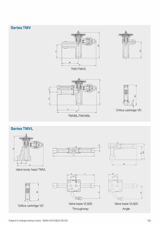
Series TMV(X)Externalpressureequalization,combi adsorber charge for seve-ral refrigerants, adjustable super-heat set., flare connections, interchangeable orifice cartridges.
Series TMV(X)BLInternal or external pressure equalization, combi adsorber charge for several refrigerants, adjustable superheat setting, inlet flare connection with optional soldering adapter, outlet solder connection, interchangeable orifice cartridges.
Series TMVL(X)Part programme valve, one valve body head for solder base with internal or external pressure equali-zation, combi adsorber charge for several refrigerants, adjustable superheat setting, interchangeable orifice cartridges.
Series TMXPart programme valve, valve body head to be combined with various bases and orifice cartridges, MOP- or liquid charge, warm thermo head, external pressure equaliza-tion in the valve body head, ad-justable superheat setting, with BalancedPort,interchangeableorifice cartridges.
Expansion valve TMVL(X)
Subjecttochangewithoutnotice·EN3H-0375GE23R0709

6
Series TLK / TLE / TLEX / TLESX with fixed orifice Capacity at: t0 = +5 °C, tc = +32 °C, subcooling = 4 K
Comparative table expansion valves
Danfoss HoneywellRefrigerant
R 1
34a
R 4
07C
R 4
04A
R
507
A
Series Orifice Capacity Capacity size [kW] [tons]
1 0.7 0.19 2 1.0 0.28 3 1.4 0.39 4 2.1 0.59 5 2.7 0.78 6 4.1 1.20 7 5.5 1.60 8 8.2 2.30 9 12.0 3.50
Series Orifice Capacity Capacity size [kW] [tons]
1 0.9 0.26 2 1.4 0.38 3 1.9 0.53 4 2.8 0.80 5 3.8 1.10 6 5.7 1.60 7 7.5 2.10 8 11.0 3.20 9 17.0 4.80
Series Orifice Capacity Capacity size [kW] [tons]
1 0.7 0.19 2 1.0 0.28 3 1.4 0.39 4 2.1 0.60 5 2.8 0.79 6 4.2 1.20 7 5.6 1.60 8 8.4 2.40 9 12.0 3.50
Orifice Capacity Capacity Series* size [kW] [tons]
0.5 0.66 0.19 0.7 0.91 0.26 1 1.3 0.38 1.5 2.1 0.61 2 2.7 0.78 2.5 3.9 1.10 3 6.3 1.79 3.5 8.3 2.37 4.5 11.3 3.21
Orifice Capacity Capacity Series* size [kW] [tons]
0.5 0.92 0.26 0.7 1.3 0.36 1 1.8 0.53 1.5 3.0 0.84 2 3.7 1.06 2.5 5.4 1.53 3 8.6 2.46 3.5 11.4 3.24 4.5 15.8 4.51
Orifice Capacity Capacity Series* size [kW] [tons]
0.5 0.69 0.20 0.7 0.99 0.28 1 1.4 0.41 1.5 2.3 0.65 2 2.9 0.82 2.5 4.2 1.18 3 6.6 1.89 3.5 8.7 2.48 4.5 12.2 3.47
TUB TUBE TUC
TUCE
TLK TLE
TLEX
TLK TLE
TLEX
TLK TLE
TLEX
TUB TUBE TUC
TUCE
TUB TUBE TUC
TUCE
Subjecttochangewithoutnotice·EN3H-0375GE23R0709 Subjecttochangewithoutnotice·EN3H-0375GE23R0709

7
Refrigerant
R 4
10A
Forexplanationsontheseseriesseepage4-5.PleasenotealsothattheseseriesofHoneywellcouldalsocomewithothertechnicaldifferences(length, weight, maximum pressures, etc.)
tons=tons(US)-->1ton(US)=3.513kW
*
Subjecttochangewithoutnotice·EN3H-0375GE23R0709
Danfoss Honeywell
Orifice size
Capacity[kW]
Capacity[tons]
Series*
0.7 1.3 0.37
TLKTLE
TLEX
1 2.3 0.66
1.5 3.7 1.06
2 4.7 1.34
2.5 6.8 1.93
3 10.9 3.10
3 10.9 3.10
3.5 14.3 4.07
4.5 19.9 5.67
4.75 26.3 7.49 TLESX
Series Orifice size
Capacity[kW]
Capacity[tons]
TUBTUBETUC
TUCE
1 1.3 0.40
2 2.1 0.60
3 2.9 0.80
4 4.5 1.30
5 5.9 1.70
6 9.0 2.50
7 12.0 3.40
8 18.0 5.00
9 26.0 7.50
R 2
2
Orifice size
Capacity[kW]
Capacity[tons]
Series*
0.5 0.90 0.27
TLKTLE
TLEX
0.7 1.3 0.36
1 1.9 0.53
1.5 3.0 0.85
2 3.8 1.08
2.5 5.5 1.55
3 8.8 2.49
3.5 11.5 3.28
4.5 16.0 4.56
Series Orifice size
Capacity[kW]
Capacity[tons]
TUBTUBETUC
TUCE
1 0.9 0.25
2 1.3 0.36
3 1.8 0.50
4 2.6 0.75
5 3.5 1.00
6 5.3 1.50
7 7.0 2.00
8 11.0 3.00
9 16.0 4.50

8
Series TLESX / TLEX with fixed orificeCapacity at: t0 = +4 °C, tc = +38 °C, subcooling = 1 K
Comparative table expansion valves
ALCO Honeywell
R 4
10A
R 2
2R
407
CR
134
a
Refrigerant
Orifice size Capacity Series* [kW]
4.5 11.8 4.75 15.9 5 20.0 TLESX 6 27.6 TLEX 7 35.3 8 43.3 10 51.0 11 65.0
4.5 16.4 4.75 21.6 5 28.0 6 40.8 6 40.8 TLESX 7 52.5 TLEX 8 61.8 10 72.3 11 92.3
3.5 14.6 4.5 20.3 4.75 26.8 5 34.8 TLESX 6 50.8 TLEX 6 50.8 7 65.3 8 76.9 10 90.0
3.5 12.2 4.5 17.0 4.75 22.4 5 29.1 TLESX 6 42.4 TLEX 7 54.5 8 64.1 10 75.1
Series Type without Type with Capacity MOP MOP [kW]
TX6-M02 TX6-M12 10.3
TX6-M03 TX6-M13 18.4
TX6 TX6-M04 TX6-M14 25.6 TX6-M05 TX6-M15 32.5 TX6-M06 TX6-M16 48.1
TX6-M07 TX6-M17 62.8
TX6-N02 TX6-N12 14.4
TX6-N03 TX6-N13 25.6
TX6-N04 TX6-N14 35.7
TX6 TX6-N05 TX6-N15 45.2
TX6-N06 TX6-N16 66.9
TX6-N07 TX6-N17 87.3
- TX6-Z12 16.0
- TX6-Z13 28.0
TX6 - TX6-Z14 40.0
- TX6-Z15 50.0
- TX6-Z16 74.0
- TX6-Z17 97.0
TX6-H02 TX6-H12 13.3
TX6-H03 TX6-H13 23.7 TX6-H04 TX6-H14 33.0 TX6 TX6-H05 TX6-H15 41.8
TX6-H06 TX6-H16 61.9
TX6-H07 TX6-H17 80.8
Subjecttochangewithoutnotice·EN3H-0375GE23R0709 Subjecttochangewithoutnotice·EN3H-0375GE23R0709

9
Series TLESX / TLEX with fixed orificeCapacity at: t0 = +5 °C, tc = +32 °C, subcooling = 4 K
Danfoss Honeywell
R 4
07C
R 1
34a
Refrigerant
Series Orifice size Capacity [kW]
3 10.5 4 14.0 6 21.0 7.5 26.0 TDE 8 28.0 TDEB 11 38.5 12.5 44.0 16 56.0 19 66.5 20 70.0 26 91.0
Series Orifice size Capacity [kW]
3 10.5 4 14.0 6 21.0 7.5 26.0 TDE 8 28.0 TDEB 11 38.5 12.5 44.0 16 56.0 19 66.5 20 70.0 26 91.0
Orifice size Capacity [kW] Series*
3.5 11.5 4.5 16.0 4.75 21.2 5 27.4 5 27.4 TLEX 6 40.0 TLESX 6 40.0 7 51.4 8 60.6 10 70.9 11 90.5
Orifice size Capacity [kW] Series*
3.5 11.4 4.5 15.8 4.75 20.9 5 27.1 5 27.1 TLEX 6 39.5 TLESX 7 50.8 7 50.8 10 70.0 10 70.0 11 89.4
Forexplanationsontheseseriesseepage4-5.PleasenotealsothattheseseriesofHoneywellcouldalsocomewithothertechnicaldifferences(length, weight, maximum pressures, etc.)
*
Subjecttochangewithoutnotice·EN3H-0375GE23R0709

10
Series Orifice Capacity Capacity size [kW] [tons]
0X 0.4 0.11
00 0.9 0.25
01 1.8 0.5
02 2.6 0.8 03 4.6 1.3 04 6.7 1.9 05 8.6 2.5 06 10.5 3.0
Orifice Capacity Capacity Series* size [kW] [tons] 0.3 0.35 0.10 0.5 0.66 0.19 0.7 0.91 0.26 1.0 1.3 0.38 1.5 2.1 0.61 2.0 2.7 0.78 2.5 3.9 1.10 3.0 6.3 1.79 3.5 8.3 2.37 4.5 11.3 3.21 4.75 15.2 4.34
TN 2TEN 2
TMV(X)TMV(X)BLTMVL(X)
Series Orifice Capacity Capacity size [kW] [tons] 0X 0.5 0.15
00 1.0 0.3
01 2.5 0.7
02 3.5 1.0 03 5.2 1.5 04 8.0 2.3 05 10.5 3.0 06 15.5 4.5
Orifice Capacity Capacity Series* size [kW] [tons] 0.3 0.49 0.14 0.5 0.94 0.27 0.7 1.28 0.36 1.0 1.87 0.53 1.5 3.0 0.85 2.0 3.8 1.08 2.5 5.5 1.55 3.0 8.8 2.49 3.5 11.5 3.28 4.5 16.0 4.56 4.75 21.2 6.02
TX 2TEX 2
Series Orifice Capacity Capacity size [kW] [tons] 0X 0.38 0.11
00 0.7 0.21
01 1.6 0.45
02 2.1 0.6
03 4.2 1.2 04 6.0 1.7 05 7.7 2.2 06 9.1 2.6
Orifice Capacity Capacity Series* size [kW] [tons] 0.3 0.37 0.10 0.5 0.69 0.20 0.7 0.99 0.28 1.0 1.4 0.41 1.5 2.3 0.65 2.0 2.9 0.82 2.5 4.2 1.18 3.0 6.6 1.89 3.5 8.7 2.48 4.5 12.2 3.47 4.75 16.1 4.57
TS 2TES 2
R 4
04A
R 2
2R
134
a
Danfoss Honeywell
Series TMV / TMVL with changeable orificeCapacity at: t0 = +5 °C, tc = +32 °C, subcooling = 4 K
Comparative table expansion valves
Refrigerant
TMV(X)TMV(X)BLTMVL(X)
TMV(X)TMV(X)BLTMVL(X)
Subjecttochangewithoutnotice·EN3H-0375GE23R0709

11
Series Orifice Capacity Capacity size [kW] [tons] 00 0.3 0.09
0 0.8 0.23
1 1.9 0.54
2 3.1 0.88
3 5.0 1.42
4 8.3 2.36 5 10.1 2.88 6 11.7 3.33
Orifice Capacity Capacity Series* size [kW] [tons] 0.3 0.36 0.10 0.5 0.69 0.20 0.7 0.96 0.27 1.0 1.4 0.39 1.5 2.2 0.63 2.0 2.9 0.82 2.5 4.0 1.15 3.0 6.6 1.87 3.5 8.7 2.48
4.5 11.8 3.35
4.75 15.9 4.53
TI-MWTIE-MWTIS-MW
TISE-MW
Series Orifice Capacity Leistung size [kW] [tons] 00 0.5 0.14
0 1.3 0.37
1 3.2 0.91
2 5.3 1.51
3 8.5 2.42 4 13.9 3.96 5 16.9 4.81 6 19.5 5.55
Orifice Capacity Capacity Series* size [kW] [tons] 0.3 0.52 0.15 0.5 0.99 0.28 0.7 1.4 0.39 1.0 2.0 0.56 1.5 3.2 0.90 2.0 4.0 1.14 2.5 5.8 1.65 3.0 9.3 2.64 3.5 12.2 3.47 4.5 17.0 4.83 4.75 22.4 6.37
TI-HWTIE-HWTIS-HW
TISE-HW
Series Orifice Capacity Capacity size [kW] [tons] 00 0.4 0.11
0 1.0 0.28
1 2.3 0.65
2 3.9 1.11
3 6.2 1.76
4 10.1 2.88
5 12.3 3.50 6 14.2 4.04
Orifice Capacity Capacity Series* size [kW] [tons] 0.3 0.36 0.10 0.5 0.68 0.19 0.7 0.97 0.28 1.0 1.4 0.40 1.5 2.2 0.64 2.0 2.8 0.80 2.5 4.1 1.17 3.0 6.5 1.86 3.5 8.6 2.44
4.5 12.0 3.41
4.75 15.8 4.49
TI-SWTIE-SWTIS-SW
TISE-SW
R 4
04A
R 2
2R
134
a
ALCO Honeywell
Series TMV / TMVL with changeable orifice Capacity at: t0 = +4 °C, tc = +38 °C, subcooling = 1 K
Refrigerant
Forexplanationsontheseseriesseepage4-5.PleasenotealsothattheseseriesofHoneywellcouldalsocomewithothertechnicaldifferences(length,weight,maximumpressures,etc.)Subjecttochangewithoutnotice·EN3H-0375GE23R0709
*
TMV(X)TMV(X)BLTMVL(X)
TMV(X)TMV(X)BLTMVL(X)
TMV(X)TMV(X)BLTMVL(X)

Type Cap. Orifice Series* [kW] cartridge
Series Type Capacity Valve cartridge [kW]
12
R 1
34a
R 4
07C
R 2
2R
404
AR
507
A
ALCO Honeywell
Series TMX with changeable orificeCapacity at: t0 = +4 °C, tc = +38 °C, subcooling = 1 K
Comparative table expansion valves
Refrigerant
TMX R134a MOP +10 °C 11.8 XD 4.5 TMX R134a MOP +10 °C 15.9 XD 4.75 TMX R134a MOP +10 °C 19.9 XD 5 TMX R134a MOP +10 °C 27.6 XD 6 TMX R134a MOP +10 °C 35.3 XD 7 TMX R134a MOP +10 °C 43.3 XD 8
TMX R134a MOP +10 °C 50.9 XD 10
TMX R407C MOP +15 °C 16.4 XD 4.5 TMX R407C MOP +15 °C 21.6 XD 4.75 TMX R407C MOP +15 °C 28.0 XD 5 TMX R407C MOP +15 °C 40.8 XD 6 TMX R407C MOP +15 °C 52.5 XD 7 TMX R407C MOP +15 °C 61.8 XD 8 TMX R407C MOP +15 °C 72.3 XD 10
TMX R22 MOP +10 °C 16.9 XD 4.5 TMX R22 MOP +10 °C 22.4 XD 4.75 TMX R22 MOP +10 °C 29.1 XD 5 TMX R22 MOP +10 °C 42.4 XD 6 TMX R22 MOP +10 °C 54.5 XD 7 TMX R22 MOP +10 °C 64.1 XD 8 TMX R22 MOP +10 °C 75.1 XD 10
TMX R404A MOP +10 °C 12.0 XD 4.5 TMX R404A MOP +10 °C 15.8 XD 4.75 TMX R404A MOP +10 °C 20.5 XD 5 TMX R404A MOP +10 °C 29.8 XD 6 TMX R404A MOP +10 °C 38.3 XD 7 TMX R404A MOP +10 °C 45.1 XD 8 TMX R404A MOP +10 °C 52.8 XD 10
TMX R507 MOP +10 °C 12.1 XD 4.5 TMX R507 MOP +10 °C 15.9 XD 4.75 TMX R507 MOP +10 °C 20.7 XD 5 TMX R507 MOP +10 °C 30.1 XD 6 TMX R507 MOP +10 °C 38.7 XD 7 TMX R507 MOP +10 °C 45.6 XD 8 TMX R507 MOP +10 °C 53.3 XD 10
400 NW 18.7 X 22440-B4B 550 NW 24.0 X 22440-B5B 750 NW 32.9 X 22440-B6B 1000 NW 44.4 X 22440-B7B 1150 NW 51.7 X 22440-B8B 14 NW 62.0 X 11873-B4B 17 NW 80.0 X 11873-B5B
300 HW 17.3 X 22440-B4B 500 HW 22.2 X 22440-B5B 750 HW 30.4 X 22440-B6B 1000 HW 41.1 X 22440-B7B 1200 HW 47.8 X 22440-B8B 14 HW 58.0 X 11873-B4B 18 HW 74.0 X 11873-B5B
250 SW 12.2 X 22440-B4B 400 SW 15.7 X 22440-B5B 600 SW 21.5 X 22440-B6B 850 SW 29.0 X 22440-B7B 1000 SW 33.8 X 22440-B8B 12 SW 40.0 X 11873-B4B 14 SW 51.0 X 11873-B5B
250 SW 12.2 X 22440-B4B 400 SW 15.7 X 22440-B5B 600 SW 21.5 X 22440-B6B 850 SW 29.0 X 22440-B7B 1000 SW 33.8 X 22440-B8B 12 SW 40.0 X 11873-B4B 14 SW 51.0 X 11873-B5B
200 MW 9.3 X 22440-B3,5B 250 MW 13.5 X 22440-B4B 350 MW 17.3 X 22440-B5B 550 MW 23.6 X 22440-B6B 750 MW 32.0 X 22440-B7B 900 MW 37.2 X 22440-B8B 11 MW 45.0 X 11873-B4B 13 MW 57.0 X 11873-B5B
TMX
TMX
TCLE
TCLE
TCLE
TCLE
TCLE
TJRE
TJRE
TJRE
TJRE
TJRE
TMX
TMX
TMX
Subjecttochangewithoutnotice·EN3H-0375GE23R0709 Subjecttochangewithoutnotice·EN3H-0375GE23R0709

13
R 1
34a
R 4
07C
R 4
04A
R
507
AR
22
Danfoss Honeywell
Series TMX with changeable orificeCapacity at: t0 = +5 °C, tc = +32 °C, subcooling = 4 K
Refrigerant
Series Valve type Orifice size Capacity [kW]
TEN 5-3.7 01 12.9 TEN 5-5.4 02 19.1 TEN 5-8.3 03 29.1 TEN 5-11.2 04 39.6 TEN 12-4.7 01 16.7 TEN 12-7.7 02 27.2 TEN 12-11.4 03 40.0 TEN 12-15 04 53.0 TE 20 TEN 20-18 01 65.0
TEZ 5-3.7 01 21.3 TEZ 5-5.0 02 29.1 TEZ 5-8.0 03 41.9 TEZ 5-13 04 59.7 TEZ 12-5.0 01 28.9 TEZ 12-8 02 46.9 TEZ 12-13 03 69.1 TEZ 12-19.5 04 91.2
TES 5-3.7 01 13.0 TES 5-5.0 02 17.6 TES 5-7.2 03 25.3 TES 5-10.3 04 36.2 TES 12-4.2 01 14.8 TES 12-6.8 02 23.9 TES 12-10.0 03 35.2 TES 12-13.4 04 47.1 TE 20 TEN 20-16.5 01 59.0
TEX 5-3 01 19.7 TEX 5-4.5 02 26.9 TEX 5-7.5 03 38.8 TEX 5-12 04 55.3 TEX 12-4.5 01 26.8 TEX 12-7.5 02 43.4 TEX 12-12 03 64.0 TEX 12-18 04 84.4
TE 5
TE 5
TE 5
TE 5
TE 12
TE 12
TE 12
TE 12
Orifice size Capacity Series* [kW]
4.75 15.2 5 19.1 6 26.4 8 41.5 4.75 15.2 6 26.4 8 41.5 10 48.8 11 62.2
4.75 20.9 5 27.1 6 39.5 8 59.8 5 27.1 7 50.8 10 70.0 11 89.4
4.75 16.0 4.75 16.0 6 30.3 7 38.9 4.75 16.0 6 30.3 7 38.9 8 45.9 10 53.7
4.75 21.2 5 27.4 6 40.0 7 51.4 5 27.4 6 40.0 8 60.6 11 90.5
TMX
TMX
TMX
TMX
Forexplanationsontheseseriesseepage4-5.PleasenotealsothattheseseriesofHoneywellcouldalsocomewithothertechnicaldifferences(length, weight, maximum pressures, etc.).
*
Subjecttochangewithoutnotice·EN3H-0375GE23R0709

14
3061
,5
78,5
122,3
30°
54
= 53,512x16x6= 60,5
53,5±216x22x6
74±264±2
±2
57
82
58
105
ca. 1
37
Made in Germany
5671
55
5454
74
Made in Germany
47,5
40
50 5075
5050
49
4017
47,5
75
Series TLESX 4.75 - 6
Series TLEX 4.75 - 7 Series TLEX 8 - 11
TLEX8-11
TLESX4.75-6
TLEX4.75-7
TLE0.5-4.5
TLEX0.5-4.5
Series TLE(X)
Dimensional drawings expansion valves
Subjecttochangewithoutnotice·EN3H-0375GE23R0709 Subjecttochangewithoutnotice·EN3H-0375GE23R0709
TMVL
lekniW - )X(SLVgnaghcruD - )X(SLVVD
TMVBL / TMVXBL
TMV / TMVX
VD
15
Series TMV
Series TMVL
TMVBL/TMVXBL
ValvebodyheadTMVL
ValvebaseVLS(X)
Throughway
ValvebaseVLS(X)
Angle
OrificecartridgeVD
OrificecartridgeVD
TMV/TMVX
Subjecttochangewithoutnotice·EN3H-0375GE23R0709

16
TMX
XBS - Durchgang
XLS - Durchgang
XD
XLS - Winkel
TMX
XBS - Durchgang
XLS - Durchgang
XD
XLS - Winkel
TMX
XBS - Durchgang
XLS - Durchgang
XD
XLS - Winkel
TMX
XBS - Durchgang
XLS - Durchgang
XD
XLS - Winkel
TMX
XBS - Durchgang
XLS - Durchgang
XD
XLS - Winkel
Dimensional drawings expansion valves
Series TMX
ValvebodyheadTMVL
OrificecartridgeVD ValvebaseXBSThroughway
ValvebaseXLSThroughwayValvebaseXLSAngle
Subjecttochangewithoutnotice·EN3H-0375GE23R0709 Subjecttochangewithoutnotice·EN3H-0375GE23R0709

17
T L KT L ET L E XT L ES X
External pressure equaliserSeries of valveConnections (L=solder, B=flare, O=O-ring)T=ThermostaticExpansionvalve
T MVT MV XT MV BLT MV X BLT MV LT M X - BT M X - L
Connections (L =solder, B = flare)External pressure equaliserSeries of valveT = Thermostatic expansion valve
Nomenclature Thermostatic expansion valves (fixed orificies)
Nomenclature Thermostatic expansion valves (changeable orifices)
Subjecttochangewithoutnotice·EN3H-0375GE23R0709
Adjustmentofoverheating
Thermo head
Valve seat
Transfer pin
Pressure equaliser
Expansion valve TLEX 0.5-4.5

18
Solenoid valves
Honeywell Solenoid Valves im-press by following advantages:
•Highdurability-minimum1.5million alternations of load
•Solidprotectionagainsthumidityby special sealing of the coil
•Modularsystem:valvehousingto be combined with various coil voltages
Solenoid Valves are used in general refrigeration and for original equipment as reliable and demand-oriented barrier of line sections. They are suitable for installation into liquid line, hot gas line and suction line of a refrigerating unit.
Practice proven design with extreme long lifetime
•Normallyclosed
•Directoperated:nominimumpressure differential required to open the valve
•Pilotoperated:minimumpressuredifferentialof0.05barrequired to open the valve
•Solderandflareconnectionspossible
Series MASolenoid Valve, normally closed, direct operated, angle construction, solder connections, kv-value = 0.17m³/h.
Series MDSolenoid Valve, normally closed, direct operated, two-way const-ruction, solder or flare connections, kv-value=0.17-0.23m³/h,valvecompletewithcoilfor230VACor as part programme valve with-out coil.
Series MSSolenoid Valve, normally closed, pilot operated, two-way construction, solder or flare connections, kv-value=0.9-4m³/h,valvecompletewithcoilfor230VACor as part programme valve with-out coil.
Subjecttochangewithoutnotice·EN3H-0375GE23R0709 Subjecttochangewithoutnotice·EN3H-0375GE23R0709
Coil gasket
Valve seat
Pilot orifice
Solenoid coil
Plunger
Direct operated solenoid valve MS

19
Medium Evaporating Condensing Subcooling Hot gas Pressure loss temperature temperature temperature across valve t0 [°C] tc [°C] ∆tc2u [K] tH [°C] ∆p [bar]
Liquid -10 25 1 - 0.40Hot gas -10 25 1 25 1.00Suction gas -10 25 1 - 0.15
Nominal capacity QN (kW)
The nominal capacity QN is based on the following conditions:
For explanations on these series see page 18. Please note also that these series of Honeywell could also come with other technical differences (length, weight, maximum pressures, etc.)
*
M A 06 2 MMSM D 10 3 SM S 16 5
Connections (S=solder in inch, MMS=solder in mm, ()=flare)Connection size in 1/8“Valve sizeDesign(A = angle - direct operated, D = direct operated, S = pilot operated)M = solenoid valves
Series MA Series MD Series MS
Nomenclature Solenoid valves
Lengthseetable
page20-21
Lengthseetable
page20-21
Lengthseetable
page20-21
Subjecttochangewithoutnotice·EN3H-0375GE23R0709
Liquid Hot gas Suction gas R134a R22 R407C R404A R134a R22 R407C R404A R134a R22 R407C R404A R507A R507A R507A
MA 062 0.17 5.21 5.62 5.39 3.87 1.14 1.47 1.45 1.29 - - - -
MD 062 0.17 5.21 5.62 5.39 3.87 1.14 1.47 1.45 1.29 - - - -
MD 102 0.22 6.74 7.27 6.98 5.01 1.48 1.90 1.88 1.67 - - - -
MD 103 0.23 7.05 7.61 7.29 5.24 1.54 1.99 1.96 1.75 - - - -
MS 103 / 104 0.9 27.6 29.8 28.5 20.5 6.04 7.78 7.67 6.83 1.54 2.06 1.92 1.80
MS 124 / 125 1.6 49.0 52.9 50.7 36.4 10.7 13.8 13.6 12.1 2.74 3.66 3.42 3.19
MS 165 / 167 2 61.3 66.1 63.4 45.5 13.4 17.3 17.1 15.2 3.42 4.57 4.27 3.99
MS 227 4 123 132 127 91.1 26.8 34.6 34.1 30.4 6.85 9.14 8.54 7.98
Type kv-value (m3/h)

20
Type kv-value Connection Length Os number Type* [m³/h] [mm]**
MS 103 0.9 5/8“ UNF 84 MS-00001 MS 103MMS 0.9 10 mm ODF 159 MS-00019 MS 103S 0.9 3/8“ ODF 159 MS-00022 part program MS 104 MMS 0.9 12 mm ODF 159 MS-00103 MC-00005 part program MS 104S 0.9 1/2“ ODF 159 MS-00104 MC-00005 MS 124 1.6 3/4“ UNF 91 MS-00007 MS 124MMS 1.6 12 mm ODF 159 MS-00023 MS 124S 1.6 1/2“ ODF 159 MS-00025 part program MS 125S 1.6 16 mm / 5/8“ ODF 159 MS-00108 MC-00005 MS 165 2 7/8“ UNF 97 MS-00012 MS 165S 2 16 mm / 5/8“ ODF 159 MS-00026 part program MS 167S 2 22 mm / 7/8“ ODF 173 MS-00111 MC-00005
MS 227S 4 22 mm / 7/8“ ODF 262 MS-00031
Type kv-value [m³/h]
Type kv-value [m³/h]
200 RB 4 0.9
200 RB 6 1.6
240 RA 8 2.3
240 RA 9 4.8 240 RA 12 5.4
110 RB 2 0.2
ALCO Honeywell Type kv-value Connection Length Os number Type* [m³/h] [mm]**
MA 062MMS 0.17 6 mm ODF
88 MA-00001
angle construction
MA 062S 0.17 1/4“ ODF
88 MA-00002
angle construction
MD 062 0.17 7/16“ UNF 65 MD-00001 MD 062MMS 0.17 6 mm ODF 112 MD-00006 MD 062S 0.17 1/4“ ODF 112 MD-00007 MD 102 0.22 7/16“ UNF 68 MD-00014 MD 102MMS 0.22 6 mm ODF 118 MD-00024 MD 102S 0.22 1/4“ ODF 118 MD-00025 MD 103 0.23 5/8“ UNF 71 MD-00018 MD 103MMS 0.23 10 mm ODF 118 MD-00026 MD 103S 0.23 3/8“ ODF 118 MD-00027
Dir
ect
op
erat
ed, n
o m
inim
um
p
ress
ure
dif
fere
nti
al r
equ
ired
Pilo
t o
per
ated
, min
imu
m p
ress
ure
d
iffe
ren
tial
of
0.05
bar
Comparative table solenoid valves
Series MA / MD / MS
MA MD
MS
Subjecttochangewithoutnotice·EN3H-0375GE23R0709 Subjecttochangewithoutnotice·EN3H-0375GE23R0709

21
Allvalvesonthisdouble-pagespreadincludeone230Vcoilandarenormallyclosed(NC).Inourpartprogramweofferallproductsalsoseparately(exceptoftheMD102).
The part program includes a choice of additional coils.
Type kv-value Connection Length Os number Type* [m³/h] [mm]**
MS 103 0.9 5/8“ UNF 84 MS-00001 MS 103MMS 0.9 10 mm ODF 159 MS-00019 MS 103S 0.9 3/8“ ODF 159 MS-00022 part program MS 104 MMS 0.9 12 mm ODF 159 MS-00103 MC-00005 part program MS 104S 0.9 1/2“ ODF 159 MS-00104 MC-00005 MS 124 1.6 3/4“ UNF 91 MS-00007 MS 124MMS 1.6 12 mm ODF 159 MS-00023 MS 124S 1.6 1/2“ ODF 159 MS-00025 part program MS 125S 1.6 16 mm / 5/8“ ODF 159 MS-00108 MC-00005 MS 165 2 7/8“ UNF 97 MS-00012 MS 165S 2 16 mm / 5/8“ ODF 159 MS-00026 part program MS 167S 2 22 mm / 7/8“ ODF 173 MS-00111 MC-00005 MS 227S 4 22 mm / 7/8“ ODF 262 MS-00031
Type kv-value Connection Length Os number Type* [m³/h] [mm]**
MA 062MMS 0.17 6 mm ODF
88 MA-00001
angle construction
MA 062S 0.17 1/4“ ODF
88 MA-00002
angle construction
MD 062 0.17 7/16“ UNF 65 MD-00001 MD 062MMS 0.17 6 mm ODF 112 MD-00006 MD 062S 0.17 1/4“ ODF 112 MD-00007 MD 102 0.22 7/16“ UNF 68 MD-00014 MD 102MMS 0.22 6 mm ODF 118 MD-00024 MD 102S 0.22 1/4“ ODF 118 MD-00025 MD 103 0.23 5/8“ UNF 71 MD-00018 MD 103MMS 0.23 10 mm ODF 118 MD-00026 MD 103S 0.23 3/8“ ODF 118 MD-00027
Type kv-value [m³/h]
EVR 2 0.16
EVR 3 0.27 Dir
ect
op
erat
ed, n
o m
inim
um
p
ress
ure
dif
fere
nti
al r
equ
ired
Pilo
t o
per
ated
, min
imu
m p
ress
ure
d
iffe
ren
tial
of
0.05
bar
Type kv-value [m³/h]
EVR 20 5
EVR 6 0.8
EVR 10 1.9
EVR 15 2.6
MA MD
MS
For explanations on these series see page 18. Please note also that these series of Honeywell could also come with other technical differences (length, weight, maximum pressures, etc.)
seedrawingonpage19
*
**
Subjecttochangewithoutnotice·EN3H-0375GE23R0709
Danfoss Honeywell

22
Sight Glasses show the con-dition of the refrigerant flowing trough the lines in the refrigera-ting plant, for example it is pos-sible to see if the refrigerant in the liquid line is free of bubbles. The moisture indicator shows the moisture content of the refrigerant.
Sight glasses
Clear view in all installation situations
Honeywell Sight Glasses stand out by the following characteris-tics:
•Minorpressureloss-optimizedconstruction without internals
•Widefieldofvisionwithoutreflections at the bottom - Refrigerantflowclearlyrecog-nizable
•Suitableforallmodernrefrigerants
•Solderandflareconnections
Series SBI Series SBIA Series SLI
Lengthseetable
page24-25
Lengthseetable page24-25
Lengthseetable page24-25
S L I 1/2S B I 10S B I A 12
Connection size (mm, inch)A = Inner and outerI = IndicatorConnections (L=solder, B=flare)S = Sight glasses
Nomenclature Sight glasses
•Mostsolidwithbrassbodyandpressure resistant glass
•Sightglasswithmoistureindi-cator to quantity the moisture content in the refrigerant
Subjecttochangewithoutnotice·EN3H-0375GE23R0709 Subjecttochangewithoutnotice·EN3H-0375GE23R0709

SBI
SBIA
SLI
23Subjecttochangewithoutnotice·EN3H-0375GE23R0709
Moisture indicatorThe colour of the indicator is a measure for the moisture load of the refrigerant inside the plant. The range of indication depends
Green colour: Moisture free. Only a moisture-free refrigerant assures no trouble with the expansion valve coming from humidity.
Refrigerant Indication Range dry (green) transition wet (yellow)
R22 < 30 ppm 30 – 150 ppm > 150 ppmR134a < 60 ppm 60 – 100 ppm > 100 ppmR404A < 20 ppm 20 – 100 ppm > 100 ppmR407C < 20 ppm 20 – 130 ppm > 130 ppmR507A < 20 ppm 20 – 100 ppm > 100 ppm
Indicationtemperature:t=30°C
ontherefrigerant.Duetothehumidity in the air, the indicator is yellowondelivery.Aftertheinstal-lation inside the plant, the indica-
Transition:When the green colour begins to fade, it is an indication that small quantities of moisture are present. It is recommended to change the filter drier.
Yellow colour: Wet.The refrigerant is loaded with moisture higher than the stated values.Achangeofthefilterdrieris required.
tor will change to green when filling the system with dry refrige-rant.
Series SBISight Glass with moisture indica-tor, flare connections, outside threads
Series SBIASight Glass with moisture indica-tor, flare connections, outside and inside thread
Series SLISight Glass with moisture indica-tor, solder connections, imperial and metric versions

24
Comparative table sight glasses
ALCO
ALCO
ALCO
Honeywell
Honeywell
Honeywell
Series Type Type Type Connection MIA AMI-1 SS AMI-1 TT
MIA M06 SS 2 MM TT 2 MM MIA 014 SS 2 TT 2 MIA M10 SS 3 MM TT 3 MM MIA 038 SS 3 TT 3 MIA M12 SS 4 MM TT 4 MM MIA MIA 012 SS 4 TT 4 AMI-1 MIA M16 SS 5 TT 5 MIA 058 SS 5 TT 5 MIA 078 SS 7 TT 7 SS 9 MM TT 9 MM SS 9 TT 9
Type Connection Os number Length Type* [mm]***
SLI 6 6 mm ODF SLI-00001 106SLI 1/4 1/4“ ODF SLI-00002 106SLI 10 10 mm ODF SLI-00003 119SLI 3/8 3/8“ ODF SLI-00004 119SLI 12 12 mm ODF SLI-00005 144SLI 1/2 1/2“ ODF SLI-00006 144 SLISLI 15 15 mm ODF SLI-00007 146SLI 16 16 mm / 5/8“ ODF SLI-00008 146SLI 16 16 mm / 5/8“ ODF SLI-00008 146SLI 18 18 mm ODF SLI-00010 183SLI 22 22 mm / 7/8“ ODF SLI-00011 183SLI 3/4 3/4“ ODF SLI-00012 183SLI 28 28 mm ODF SLI-00014 187SLI 1.1/8 1 1/8“ ODF SLI-00015 178
Type Thread size** Os number Length Type* [mm]***
SBI 6 7/16 UNF SBI-00001 70SBI 10 5/8 UNF SBI-00002 76SBI 12 3/4 UNF SBI-00003 88SBI 16 7/8 UNF SBI-00004 98
Type Thread size** Os number Length Type* [mm]***
SBIA 6 7/16 UNF SBIA-00001 60SBIA 10 5/8 UNF SBIA-00002 76SBIA 12 3/4 UNF SBIA-00003 74SBIA 16 7/8 UNF SBIA-00004 78
Series Type MIA Connection size**
MM 2 6 mm / 1/4“ MM 3 10 mm / 3/8“ MM 4 12 mm / 1/2“ MM 5 16 mm / 5/8“
Series Type MIA Connection size**
FM 2 6 mm / 1/4“ FM 3 10 mm / 3/8“ FM 4 12 mm / 1/2“
AMI-1
AMI-1
SBI
SBIA
Con
nect
ion
size
s ar
e eq
ual t
o th
e on
es o
f H
oney
wel
l in
the
right
-han
d ta
ble
Series SBI / SBIA / SLI
Subjecttochangewithoutnotice·EN3H-0375GE23R0709 Subjecttochangewithoutnotice·EN3H-0375GE23R0709

25
Danfoss
DanfossSeries Type Type Type Connection MIA AMI-1 SS AMI-1 TT
SGI 6s SGN 6s SGI 6s SGN 6s SGH 6s SGI 10s SGN 10s SGI 10s SGN 10s SGH 10s SGI 12s SGN 12s SG 12 /
SGN 12s SGH 12s
SGI 12s SG 16 /
SGN 16s SGH 16s
SGI 16s SGI 18s SGN 18s SGI 22s SGN 22s SGH 22s SGI 19s SGN 19s SGN 22s SGH 22s
Series Type Type Connection SG/SGI SGN/SGH size**
SGI 6
SGN 6 / 6 mm / 1/4“
SGH 6 SG 10 /
SGN 10 10 mm / 3/8“
SGI 10 SGI 12 SGN 12 12 mm / 1/2“ SGI 16 SGN 16 16 mm / 5/8“
SG SGI SGN
SG SGI SGN SGH
Type Connection Os number Length Type* [mm]***
SLI 6 6 mm ODF SLI-00001 106SLI 1/4 1/4“ ODF SLI-00002 106SLI 10 10 mm ODF SLI-00003 119SLI 3/8 3/8“ ODF SLI-00004 119SLI 12 12 mm ODF SLI-00005 144
SLI 1/2 1/2“ ODF SLI-00006 144 SLI 15 15 mm ODF SLI-00007 146
SLI 16 16 mm / 5/8“ ODF SLI-00008 146
SLI 18 18 mm ODF SLI-00010 183SLI 22 22 mm / 7/8“ ODF SLI-00011 183SLI 3/4 3/4“ ODF SLI-00012 183SLI 28 28 mm ODF SLI-00014 187SLI 1.1/8 1 1/8“ ODF SLI-00015 178
Type Thread size** Os number Length Type* [mm]***
SBI 6 7/16 UNF SBI-00001 70
SBI 10 5/8 UNF SBI-00002 76
SBI 12 3/4 UNF SBI-00003 88SBI 16 7/8 UNF SBI-00004 98
SBI
SLI
Type Thread size** Os number Length Type* [mm]***
SBIA 6 7/16 UNF SBIA-00001 60SBIA 10 5/8 UNF SBIA-00002 76SBIA 12 3/4 UNF SBIA-00003 74SBIA 16 7/8 UNF SBIA-00004 78
SBIA
Honeywell
Honeywell
HoneywellDanfossSeries Type Type Connection SG/SGI SGN size**
SGI 6 SGN 6 6 mm / 1/4“ SGI 10 SGN 10 10 mm / 3/8“ SGI 12 SGN 12 12 mm / 1/2“ SGI 16 SGN 16 16 mm / 5/8“
SGI SGN
Con
nect
ion
size
s ar
e eq
ual t
o th
e on
es o
f H
oney
wel
l in
the
right
-han
d ta
ble
Forexplanationsontheseseriesseepage23.PleasenotealsothattheseseriesofHoneywellcouldalsocomewithothertechnicaldifferences(length, weight, maximum pressures, etc.)
Honeywell uses the thread size for flare connections always. Flare connections of competitive products are given here in connection sizes of the tubes.
see drawing on page 22.
*
**
***
Subjecttochangewithoutnotice·EN3H-0375GE23R0709

26
Filter Drier are used for filtering impurities out of the refrigerant and for moisture removal. They are placed in the liquid line of air-conditioning, refrigeration and deep freeze systems.
Filter drier
Premium filters with high filter performance
HoneywellFilterDriersstandoutby the following characteristics:
•Bulkdrierwithminorpressureloss – High abrasion resistance
•Highcoolingcapacity
•Dryingmedium:3Åmolecularsieve and activated alumina
•Highwaterabsorbingcapacity
FF 05 2FF 08 3 SFF 16 4 MMS
Connections (S=solder in inch, MMS=solder in mm, ()=flare)Connection size in 1/8“Filter sizeFF = filter drier
Series FF
FF Flare connection
Lengthseetable page28-29
Lengthseetable page28-29
FF Solder connection
•Reliablefilterperformance
•Continuousrangewithsolderorflare connections
•Lowpressuredrop
•Anymountingpositionintheliquid line possible
Subjecttochangewithoutnotice·EN3H-0375GE23R0709 Subjecttochangewithoutnotice·EN3H-0375GE23R0709
NomenclatureFilter drier

27
FF Flare connection
FF Solder connection
Subjecttochangewithoutnotice·EN3H-0375GE23R0709
Water adsorption rate [g]
Refrigerant R134a R22 R404A R407C R507Final moisture 50 ppm 60 ppm 50 ppm 50 ppm 50 ppm
24 °C 52 °C 24 °C 52 °C 24 °C 52 °C 24 °C 52 °C 24 °C 52 °C
030 4.0 3.7 3.9 3.6 4.3 4.0 3.6 3.1 4.4 4.0 050 7.8 7.2 7.5 6.9 8.3 7.7 7.0 5.9 8.5 7.8 080 12.6 11.6 12.1 11.1 13.4 12.4 11.2 9.6 13.7 12.5 160 25.1 23.2 24.1 22.2 26.7 24.8 22.4 19.1 27.4 24.9 300 48.5 44.8 46.7 42.9 51.7 47.9 43.2 37.0 52.9 48.2 410 67.2 62.0 64.6 59.4 71.6 66.4 59.9 51.2 73.3 66.8
Liquidtemperature
Type
Series FF ... S/MMSFilterDrierwithsolderconnections(S = imperial; MMS = metric), drying agent in bulk
Series FF ...FilterDrierwithflareconnections,drying agent in bulk

28
Comparative table filter drier
ALCO Honeywell
Series FF
Series Type Connection**
ADK-032 6 mm / 1/4“ ADK-052 6 mm / 1/4“ ADK-053 10 mm / 3/8“ ADK-082 6 mm / 1/4“ ADK-083 10 mm / 3/8“ ADK-084 12 mm / 1/2“ ADK-162 6 mm / 1/4“ ADK-163 10 mm / 3/8“ ADK-164 12 mm / 1/2“ ADK-165 16 mm / 5/8“ ADK-303 10 mm / 3/8“ ADK-304 12 mm / 1/2“ ADK-305 16 mm / 5/8“ ADK-414 12 mm / 1/2“ ADK-415 16 mm / 5/8“
ADK-036MMS 6 mm ODF ADK-032S 1/4“ ODF ADK-056MMS 6 mm ODF ADK-052S 1/4“ ODF ADK-0510MMS 10 mm ODF ADK-053S 3/8“ ODF ADK-086MMS 6 mm ODF ADK-082S 1/4“ ODF ADK-0810MMS 10 mm ODF ADK-083S 3/8“ ODF ADK-0812MMS 12 mm ODF ADK-084S 1/2“ ODF ADK-1610MMS 10 mm ODF ADK-163S 3/8“ ODF ADK-1612MMS 12 mm ODF ADK-164S 1/2“ ODF ADK-165S 5/8“ ODF ADK-304S 1/2“ ODF ADK-305S 5/8“ ODF ADK-307S 22 mm / 7/8“ ODF ADK-415S 5/8“ ODF ADK-417S 22 mm / 7/8“ ODF
Type Connection** Os number Length Type* [mm]***
FF 032 7/16“ UNF FF-00201 108.5 FF 052 7/16“ UNF FF-00204 121.5FF 053 5/8“ UNF FF-00207 127.5FF 082 7/16“ UNF FF-00210 149.5FF 083 5/8“ UNF FF-00213 155.5FF 084 3/4“ UNF FF-00216 159.5FF 162 7/16“ UNF FF-00219 169.0FF 163 5/8“ UNF FF-00222 175.0FF 164 3/4“ UNF FF-00225 179.0FF 165 7/8“ UNF FF-00228 183.0FF 303 5/8“ UNF FF-00230 251.5FF 304 3/4“ UNF FF-00233 255.5FF 305 7/8“ UNF FF-00236 259.5FF 414 3/4“ UNF FF-00239 252.5FF 415 7/8“ UNF FF-00242 273.5
FF 032MMS 6 mm ODF FF-00202 98.5FF 032S 1/4“ ODF FF-00203 98.5FF 052MMS 6 mm ODF FF-00205 111.5FF 052S 1/4“ ODF FF-00206 111.5FF 053MMS 10 mm ODF FF-00208 111.5FF 053S 3/8“ ODF FF-00209 111.5FF 082MMS 6 mm ODF FF-00211 139.5FF 082S 1/4“ ODF FF-00212 139.5FF 083MMS 10 mm ODF FF-00214 139.5FF 083S 3/8“ ODF FF-00215 139.5FF 084MMS 12 mm ODF FF-00217 139.5FF 084S 1/2“ ODF FF-00218 139.5FF 162MMS 6 mm ODF FF-00220 159.0FF 162S 1/4“ ODF FF-00221 159.0FF 163MMS 10 mm ODF FF-00223 159.0FF 163S 3/8“ ODF FF-00224 159.0FF 164MMS 12 mm ODF FF-00226 159.0FF 164S 1/2“ ODF FF-00227 159.0FF 165S 16 mm / 5/8“ ODF FF-00229 163.0FF 303MMS 10 mm ODF FF-00231 235.5FF 303S 3/8“ ODF FF-00232 235.5FF 304MMS 12 mm ODF FF-00234 235.5FF 304S 1/2“ ODF FF-00235 235.5FF 305S 16 mm / 5/8“ ODF FF-00237 239.5FF 307S 22 mm / 7/8“ ODF FF-00238 259.5FF 414MMS 12 mm ODF FF-00240 232.5FF 414S 1/2“ ODF FF-00241 232.5FF 415S 16 mm / 5/8“ ODF FF-00243 253.5FF 417S 22 mm / 7/8“ ODF FF-00244 273.5
Fla
re c
on
nec
tio
nS
old
er c
on
nec
tio
n
ADK FF
ADK FF
Biflowdrier/drierreceiverandotherfiltersordriersareavailableonenquiry.
Subjecttochangewithoutnotice·EN3H-0375GE23R0709 Subjecttochangewithoutnotice·EN3H-0375GE23R0709

29
Danfoss Honeywell
Series Type DCL Type DML Connection**
DCL 032 DML 032 6 mm / 1/4“ DCL 052 DML 052 6 mm / 1/4“ DCL 053 DML 053 10 mm / 3/8“ DCL 082 DML 082 6 mm / 1/4“ DCL 083 DML 083 10 mm / 3/8“ DCL 084 DML 084 12 mm / 1/2“ DCL 162 DML 162 6 mm / 1/4“ DCL 163 DML 163 10 mm / 3/8“ DCL 164 DML 164 12 mm / 1/2“ DCL 165 DML 165 16 mm / 5/8“ DCL 303 DML 303 10 mm / 3/8“ DCL 304 DML 304 12 mm / 1/2“ DCL 305 DML 305 16 mm / 5/8“ DCL 414 DML 414 12 mm / 1/2“ DCL 415 DML 415 16 mm / 5/8“
DCL 032s DML 032s 6mm ODF DCL 032s DML 032s 1/4“ ODF DCL 052s DML 052s 6mm ODF DCL 052s DML 052s 1/4“ ODF DCL 053s DML 053s 10mm ODF DCL 053s DML 053s 3/8“ ODF DCL 082s DML 082s 6mm ODF DCL 082s DML 082s 1/4“ ODF DCL 083s DML 083s 10mm ODF DCL 083s DML 083s 3/8“ ODF DCL 084s DML 084s 12mm ODF DCL 084s DML 084s 1/2“ ODF DCL 162s DML 162s 6mm ODF DCL 162s DML 162s 1/4“ ODF DCL 163s DML 163s 10mm ODF DCL 163s DML 163s 3/8“ ODF DCL 164s DML 164s 12mm ODF DCL 164s DML 164s 1/2“ ODF DCL 165s DML 165s 16 mm / 5/8“ ODF DCL 303s DML 303s 10mm ODF DCL 303s DML 303s 3/8“ ODF DCL 304s DML 304s 12mm ODF DCL 304s DML 304s 1/2“ ODF DCL 305s DML 305s 16 mm / 5/8“ ODF DCL 307s DML 307s 22 mm / 7/8“ ODF DCL 414s DML 414s 12mm ODF DCL 414s DML 414s 1/2“ ODF DCL 415s DML 415s 16 mm / 5/8“ ODF DCL 417s DML 417s 22 mm / 7/8“ ODF
Type Connection** Os number Length Type* [mm]***
FF 032 7/16“ UNF FF-00201 108.5FF 052 7/16“ UNF FF-00204 121.5 FF 053 5/8“ UNF FF-00207 127.5 FF 082 7/16“ UNF FF-00210 149.5 FF 083 5/8“ UNF FF-00213 155.5 FF 084 3/4“ UNF FF-00216 159.5 FF 162 7/16“ UNF FF-00219 169.0 FF 163 5/8“ UNF FF-00222 175.0 FF 164 3/4“ UNF FF-00225 179.0 FF 165 7/8“ UNF FF-00228 183.0 FF 303 5/8“ UNF FF-00230 251.5 FF 304 3/4“ UNF FF-00233 255.5 FF 305 7/8“ UNF FF-00236 259.5 FF 414 3/4“ UNF FF-00239 252.5 FF 415 7/8“ UNF FF-00242 273.5
FF 032MMS 6 mm ODF FF-00202 98.5FF 032S 1/4“ ODF FF-00203 98.5 FF 052MMS 6 mm ODF FF-00205 111.5 FF 052S 1/4“ ODF FF-00206 111.5 FF 053MMS 10 mm ODF FF-00208 111.5 FF 053S 3/8“ ODF FF-00209 111.5 FF 082MMS 6 mm ODF FF-00211 139.5 FF 082S 1/4“ ODF FF-00212 139.5 FF 083MMS 10 mm ODF FF-00214 139.5 FF 083S 3/8“ ODF FF-00215 139.5 FF 084MMS 12 mm ODF FF-00217 139.5 FF 084S 1/2“ ODF FF-00218 139.5 FF 162MMS 6 mm ODF FF-00220 159.0 FF 162S 1/4“ ODF FF-00221 159.0 FF 163MMS 10 mm ODF FF-00223 159.0 FF 163S 3/8“ ODF FF-00224 159.0 FF 164MMS 12 mm ODF FF-00226 159.0 FF 164S 1/2“ ODF FF-00227 159.0 FF 165S 16 mm/5/8“ ODF FF-00229 163.0 FF 303MMS 10 mm ODF FF-00231 235.5 FF 303S 3/8“ ODF FF-00232 235.5 FF 304MMS 12 mm ODF FF-00234 235.5 FF 304S 1/2“ ODF FF-00235 235.5 FF 305S 16 mm / 5/8“ ODF FF-00237 239.5 FF 307S 22 mm / 7/8“ ODF FF-00238 259.5 FF 414MMS 12 mm ODF FF-00240 232.5 FF 414S 1/2“ ODF FF-00241 232.5 FF 415S 16 mm / 5/8“ ODF FF-00243 253.5 FF 417S 22 mm / 7/8“ ODF FF-00244 273.5
Fla
re c
on
nec
tio
nS
old
er c
on
nec
tio
n
DCL DML
FF
DCL DML
FF
Forexplanationsontheseseriesseepage26-27.PleasenotealsothattheseseriesofHoneywellcouldalsocomewithothertechnicaldifferen-ces (length, weight, maximum pressures, etc.)
Honeywell uses the thread size for flare connections always. Flare connections of competitive products are given here in connection sizes of the tubes.
see drawing on page 26.
*
**
***
Subjecttochangewithoutnotice·EN3H-0375GE23R0709

30
Additional cooling components
Check ValvesCheck Valves are installed in the liquid, hot gas or suction line of a refrigerated plant. They prevent flow reversion in the circuit e.g. caused by liquid migration. This is realized by a spring loaded piston which opens the valve only in one direction.
Vibration AbsorbersHoneywellVibrationAbsorbersare used to minimize vibrations on the pipes caused by the com-pressor. Furthermore they decrease noise and compensate small thermal distensions.
Check Valves
Vibration Absorbers
Hot Gas Bypass Valves
RV
SA
Liquid Injection Valves
Hot Gas Bypass ValvesHoneywellHotGasBypassVal-ves are used to adjust the com-pressor capacity to the actual evaporator capacity in a refrige-ratingplant.TheHotGasBypassValve can be installed in a by-pass tube between hot gas line and suction line. The suction pressure is downward limited by flowing hot gas from the high pressure to the low pressure side e.g. as freezing protection. The controllers are suitable for plants in general refrigeration and for original equipment such as dehu-midifiers, air driers, water coolers or ice machines.
Liquid Injection ValvesLiquidInjectionValvesareusedinrefrigeration applications to reduce the temperature of the suction gas.Dependingonthesuperheatof the compressor suction gas, liquid refrigerant is injected into the suction line. Thereby the suction gas is cooled down. HoneywellLiquidInjectionValvescan be combined optimally with HotGasBypassValves.
•Highflexibilityduetomodularsystem
• Interchangeableorifice cartridges
•Optimaladjustmenttocoolingcapacity due to small orifice graduation
•Tobeusedwithbasesandorifi-cecartridgesofHoneywellEx-pansion Valves
Honeywell - Application experience with cooling components
Subjecttochangewithoutnotice·EN3H-0375GE23R0709 Subjecttochangewithoutnotice·EN3H-0375GE23R0709
CVC
NMVL
NMXHLEX 4.75 – 7 HLEX 8 – 11
HLE

31
Electronic cooling components
Individual Solutions from HoneywellHoneywell offers a wide range of ElectronicControlsforthefailsafeoperation of cooling, refrigeration, air conditioning and heat pump applications.TemperatureDis-plays, Thermostats and Cold Store Controls show just a small selection of the complete port- folio. We do have much more. Askus!
ThermostatsHoneywell Thermostats are used for refrigeration and deep freeze systems, heat pumps as well as for general thermostat applica-tions.TheElectronicThermostatscan be used for cooling and heating applications in a tempera-turerangeof-55°Cto+50°C.
Temperature DisplaysHoneywellElectronicTemperatureDisplaysareusedinrefrigerationand deep freeze systems, in cold stores and as general tempera-ture display.
Cold Store ControlsHoneywell Cold Store Controls are used for refrigeration and deep freeze systems. They cont-rol the cold store temperature by switching the compressor and evaporator fan depending on the adjusted parameters.
Cold Store Controls Thermostats and Temperature Displays
Individual Solutions from Honeywell
PCR 300PCR 100
PCR 110 PTI 610
PCR 310
Honeywell - Optimal control of refrigerating plants
Subjecttochangewithoutnotice·EN3H-0375GE23R0709 Subjecttochangewithoutnotice·EN3H-0375GE23R0509

32
Overview of typesTo shortly give you an overwiev of how our products are designed we displayed the main types here. More detailed information can be found on our website or by just calling us.
Automatic Expansion Valves
Thermostatic Expansion Valves with fixed orifice
AEL
TLK TLE(X) 0.5 – 4.5 TLEX 4.75 – 11TLESX
AMV(X)
Thermostatic Expansion Valves with interchangeable orifice
TMV(X)
MDMA
FF
FF
MS
TMV(X)BL TMXTMVL(X)
Solenoid Valves
Sight Glasses
Filter Drier
Subjecttochangewithoutnotice·EN3H-0375GE23R0509
SBI
SBIA
SLI

33
On the internet you can find detailed information about the cooling components of Honeywell. www.honeywell-cooling.com
•LinkProducts Technical information, data sheets, mounting guidelines and certificates to download
•LinkSelection Software Selection software „Valve Tool“ to download and for free usage
•LinkContacts Requestofadditionalinformati-on, world-wide contacts
Our online service
Subjecttochangewithoutnotice·EN3H-0375GE23R0709
Please note: Doyouprefertohavethatinfor-mationonCD?Thenpleaseorderyour personal copy by sending an E-mailto(donotforgettomenti-on your address):

Automation and Control Solutions Honeywell GmbH Hardhofweg 74821Mosbach/Germany Phone: +49626181-475 Fax: +49626181-461 [email protected] www.honeywell-cooling.com
EN3H-0375GE23R0709 Subject to change without notice©2009HoneywellGmbH
Subjecttochangewithoutnotice·EN3H-0375GE23R0709