product note - digchipapplication-notes.digchip.com/018/18-27032.pdf · tch bts uplink wnlink gsm...
TRANSCRIPT

Agilent PN ESG-1
Using the Agilent ESG-D Series of RF Signal Generators and theAgilent 8922 GSM Test Set for GSM ApplicationsProduct Note

2
3
3
10
15 15192020
23
26
28
31
313335
39
40
41
42
Introduction
Introduction to GSM
Generating a 0.3 GMSK Modulated Burst Signal for GSM(DCS 1800 & PCS 1900) Using the Agilent ESG-D SeriesSignal Generator
Data GenerationChoosing data patternsSingle / continuous data patternsData dependenciesGenerating long data patterns, such as a GSM superframe
Triggering a GSM Frame
Customizing the GSM Mode
Adjacent Broadcast Channel Generation Using the Agilent ESG-D Series Signal Generator and the Agilent 8922 GSM Test Set
Using the Agilent ESG-D Series Signal Generator and the Agilent 8922 GSM Test Set to Carry Out GSM Receiver TestsReceiver co-channel rejectionAdjacent channel rejectionReceiver intermodulation rejection
Translating ARFCNs into Absolute Frequency Values forGSM Systems
Glossary of Terms
Specifications
Related Literature
Table of Contents
3
1. IntroductionThe ESG series RF signal generators from AgilentTechnologies provides precise frequency and levelcontrol, modulation (AM, FM, phase modulationand pulse modulation), a choice of frequency cov-erage from 250 kHz to 1, 2, 3 or 4 GHz, and aneasy-to-use interface. The digital family, the ESG-Dseries, adds versatile I/Q digital modulation capa-bilities and six built-in communications standards(GSM, DECT, TETRA, NADC, PHS and PDC) areprovided with the optional IQ baseband generator(Options UN3 & UN4). Accessible at the touch of abutton, these built-in communications personali-ties are easy to configure to meet user-defined testrequirements. The ESG-D series provides operatorsmeasurement versatility by offering a choice ofinternal or external data generation, and flexibleframing, timeslot and power burst profile configu-ration capabilities.
The purpose of this product note is to show how touse the ESG-D series signal generators to generatea digitally modulated signal for the Global Systemfor Mobile Communications (GSM). Details willalso be given on how the ESG-D series signal gener-ators can be used with the Agilent 8922 GSM TestSet for GSM applications.
2. Introduction to GSMThe Global System for Mobile Communications(GSM) is the most successful digital cellular systemin operation today. Although GSM originated inEurope, it is quickly gaining world-wide accept-ance and is being adopted as a standard in manycountries.
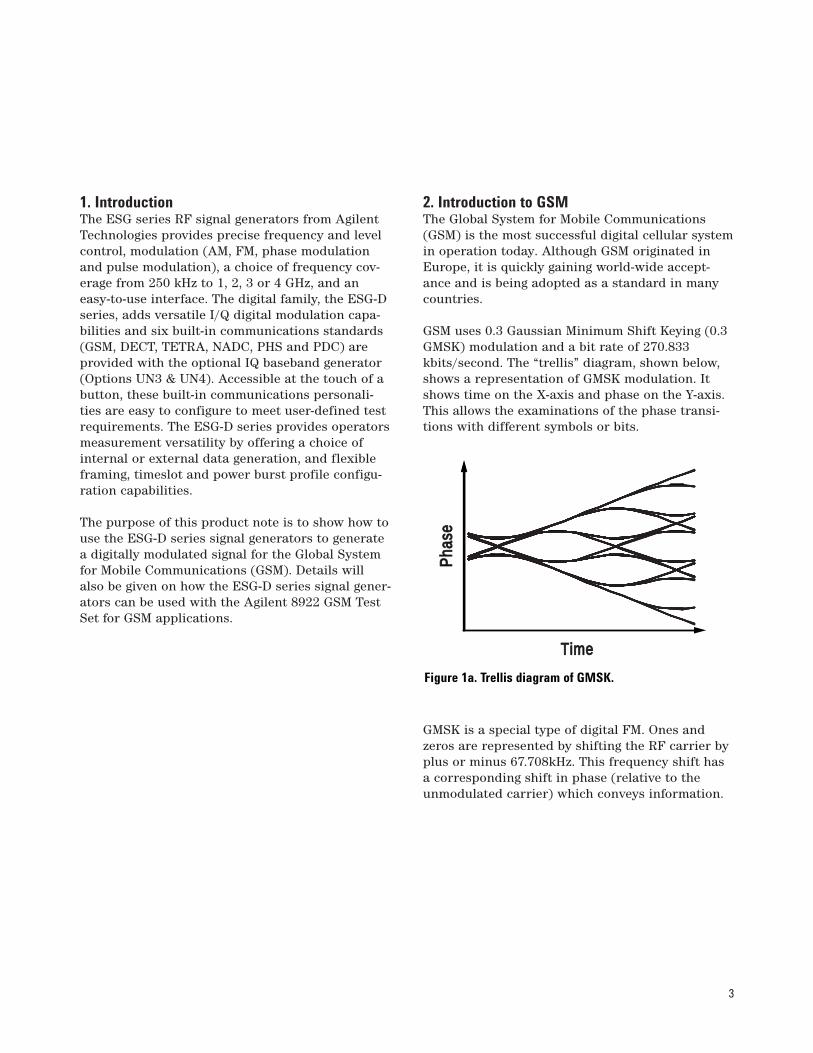
GSM uses 0.3 Gaussian Minimum Shift Keying (0.3GMSK) modulation and a bit rate of 270.833kbits/second. The “trellis” diagram, shown below,shows a representation of GMSK modulation. Itshows time on the X-axis and phase on the Y-axis.This allows the examinations of the phase transi-tions with different symbols or bits.
GMSK is a special type of digital FM. Ones andzeros are represented by shifting the RF carrier byplus or minus 67.708kHz. This frequency shift hasa corresponding shift in phase (relative to theunmodulated carrier) which conveys information.
Time
Pha
seP
hase
Figure 1a. Trellis diagram of GMSK.

4
If a long series of ones were sent, the result wouldbe a series of positive phase transitions of 90degrees per bit. If a long series of zeros were sent,there would be a constant declining phase of 90degrees per bit. Typically, there would be interme-diate transmissions with random data.
The modulation spectrum is reduced by applying aGaussian pre-modulation filter. This slows downthe rapid frequency transitions which would other-wise spread energy into adjacent channels. WhenGaussian filtering is applied, the phase makesslower direction changes and this prevents thephase trajectory from meeting its 90 degree targetpoints. The exact phase trajectory is very tightlycontrolled—the GSM specifications allow no more
than 5 degrees rms and 20 degrees peak deviationfrom the ideal trajectory. The 0.3 mentioned abovedescribes the bandwidth of the Gaussian filter withrelation to the bit rate, and is more commonlycalled the filter alpha or the Bandwidth-by-Time prod-uct (BbT).
The GSM system consists of Mobile Stations (MS),both hand-held portables and mobiles mounted ina car, which communicate with the Base StationSystem (BSS) over the RF air interface. The BSStypically consists of a Base Transceiver System(BTS) and a Base Station Controller (BSC) whichare connected by a link called the Abis interface.The Abis interface is often a microwave link, butcan also be a cable or an optical fibre.
Data
Frequency
Phase
+67.708 kHz
-67.708 kHz
270.833kB/s
+90° -90°I
Q
Broadcast Channel
BCH
TrafficChannel
ToBSC
AbisInterface
TCH BTSUplink
Downlink
GSM
GSM
GSMGSM
GSM
Figure 1b. 0.3 GMSK
Figure 2. Diagram of GSM cell

5
The BTS is fitted with a number oftransmitter/receiver (or transceiver) modules, thenumber of which determines the number of fre-quency channels that can be used in the GSM cell.Its exact configuration varies depending on thenumber of users expected in the cell. All BTSs con-tinually produce a Broadcast Channel (BCH). TheBCH is like a beacon—it allows mobiles to find theGSM network. The BCH consists of various partsfor frequency correction, synchronization, controland access. The BCH is received by all mobiles inthe cell, whether they are on a call or not.
Mobiles on a call use a TCH (Traffic Channel). TheTCH is a two way channel used to exchange speech
information between the mobile and base-station.Using Frequency Division Multiple Access (FDMA),information is divided into the uplink and down-link, depending on its direction of flow. The uplinkis for mobile transmission and the downlink is forbase station transmission. Within each band thechannel numbering scheme is the same, however,the uplink and downlink bands are 45 MHz apart.
Each band is then divided into 200 kHz channelscalled Absolute Radio Frequency Channel Numbers(ARFCN). In addition to frequency division, time isalso divided into segments using Time DivisionMultiple Access (TDMA).
51Frames
FCH Frames 0, 10, 20, 30, 40
SCH Frames 1, 11, 21, 31, 41
BCCH Frames 2-5
CCCH Frames 6-9, 12-19
SDCCH Frames 22-29, 32-39
SACCH Frames 42-49
Frame 50 is idle
2 3 00 11
Figure 3. Diagram of BCH

6
Each ARFCN is shared between up to 8 mobiles.Since there are a maximum of eight users per fre-quency, there are eight timeslots (TS) per GSMframe. Each timeslot lasts 576.92µs and contains156.25 bits of information, although only 148 ofthese bits are used for data. The remaining bits areused for “guard” time. The pattern repeats, givingthe users another timeslot each frame. Therefore,each mobile (user) uses the ARFCN for one time-slot and then waits for its turn to come roundagain in the next frame.
The mobile transmitter turns on only during itsactive timeslot. The requirement to transmit inonly one single timeslot and stay idle during the
remaining seven timeslots results in very tightdemands on the switching on and off of the RFpower. If a mobile station does not perform accord-ing to the specifications, it will disturb othermobile stations in adjacent timeslots and on adja-cent channels. The GSM specifications make sure amobile’s emissions remain in its assigned channelby specifying a power-versus-time template, shownin Figure 5. During the central, or “useful,” part ofthe TDMA burst (corresponding to 147 bits) whendata is being transmitted, the mobile has to controlits output to within +/–1dB of the mean value. Thispulsed transmission is not only defined for themobile station but is also generally defined forbase stations.
1 2 3
45
6
3
4 5 67
01
2
Time
Frequency
Amplitude
ARFCN
Timeslot
Physical Channel is an ARFCN and Timeslot 7
Figure 4. Diagram of ARFCNs
+1.0 dB
–1.0 dB
+4 dB
–6 dB
–30 dB
–70 dB
–6 dB
–30 dB
–70 dB
147 "Useful" Bits542.72µs
148 "Active" Bits, 546.42µs
3 57 1 26 1 57 310µs 8µs 10µs 10µs 10µs8µs
Pow
er
Time
Figure 5. GSM TDMA burst

7
The ETSI GSM 05.05 specifications also define theAdjacent Channel Power (ACP) performancerequired by both mobile and base stations. TheACP specifications define the performancerequired by the mobile and base stations outsidetheir assigned channels. The ACP is usuallydefined at 1 channel (200kHz), 2 channel (400kHz),3 channel (600kHz), etc. offsets from the assignedchannel. Both the modulation process and thepower ramping up and down (switching transients)affect the output RF spectrum. The required ACPperformance due to these two effects is defined inthe ETSI GSM 05.05 specifications. The diagramand table below illustrate the excellent ACP per-formance available with the ESG-D signal genera-tor (configured with Option UN3 or Option UN4).It can clearly be seen from the table that the ESG-D complies with the ETSI specifications.
10 dB/div
4dBm
CENTER 920 MHz SPAN 2 MHz
+4 dBm PN15
Figure 6. Agilent ESG-D GSM RF output profile (burst mode)
Table 1: Summary of Agilent ESG-D GSM ACP performance vs. ETSI GSM 05.05 recommendations(ACP given in dBc, except where stated otherwise)
Spectrum due to modulation Spectrum due to switching
Offset from carrier (kHz) 200 400 600 1,200 200 400 600 1,200
ETSI spec. (30 kHz measurement bandwidth) BS (at max power) –30 –60 –70 –73 --- –57 –67 –74MS (at max power) –30 –60 –66 –66 --- –23 dBm –26 dBm –32 dBm
Agilent ESG-D spec. (30kHz measurement bandwidth) –37 –71 –81 <–83 –37 –69 –79 –81

8
As mentioned earlier, eight time-slots make up aGSM frame. Frames are then grouped together tomake multiframes. Speech multiframes (such as aTCH) consist of 26 frames, while signaling datamultiframes (such as a BCH) are made up of 51frames. A superframe consists of 26 or 51 multi-frames.
How are GSM, DCS1800 and PCS1900 different? GSM is a family of digital cellular systems. Theterm GSM can be used collectively to describe theGSM900 and DCS1800 standards. GSM900 is theoriginal GSM system, using frequencies in the 900MHz band and is designed for wide area cellularoperation. DCS1800 is an adaptation of GSM900.Creating DCS1800 involved widening the bandsassigned to GSM and moving them up to 1.8 GHz.To avoid confusion, the channel numbers (ARFCN)used for GSM900 channels run from 1 to 124, andthe ARFCNs for DCS1800 run from 512 to 885.With wider frequency allocation, leading to morechannels, DCS1800 is able to cope with higher userdensities. DCS1800 mobiles are also designed forlower output powers (up to 1W), so cell sizes haveto be smaller, meaning even higher densities. In allother respects, GSM900 and DCS1800 are the
same. The GSM Phase II specifications (a revisedand re-written standard) brings the two systemseven closer. GSM900 gets additional bandwidthand channels, called E-GSM (Extended band GSM)and lower power control levels for mobiles, allow-ing micro-cell operation. These two features allowincreased user densities in GSM systems. Phase IIalso makes provision for the addition of new serv-ices on GSM and DCS1800. The addition of specificservices such as data, fax and dual mode operationis currently being defined in what is referred to asPhase II+. In the USA, bands have been releasedaround 2 GHz for a PCS (Personal CommunicationsSystem). The ready availability of GSM equipmentand expertise has made GSM at 1.9GHz veryattractive for many operators. In technical termsPCS1900 will be identical to DCS1800 except forfrequency allocation and power levels.
6.12s
3 1 1 326 bits 57 bits57 bits
Control bit
Control bit
Midamble GuardPeriod
DataData
8.25 bits
Tailbits
Tailbits
120ms
4.615ms
576.92 µs
Superframe
Multiframe
Frame
Timeslot(normal burst)
26 Frames
51 Multiframes
8 Timeslots
156.25 Bits
Figure 7. Diagrams of frames, multiframes, superframes
9
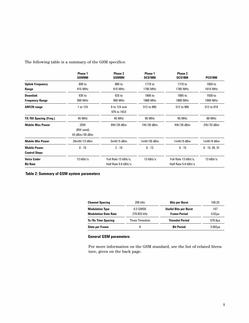
Table 2: Summary of GSM system parameters
Phase 1 Phase 2 Phase 1 Phase 2GSM900 GSM900 DCS1800 DCS1800 PCS1900
Uplink Frequency 890 to 880 to 1710 to 1710 to 1850 to
Range 915 MHz 915 MHz 1785 MHz 1785 MHz 1910 MHz
Downlink 935 to 925 to 1805 to 1805 to 1930 to
Frequency Range 960 MHz 960 MHz 1880 MHz 1880 MHz 1990 MHz
ARFCN range 1 to 124 0 to 124 and 512 to 885 512 to 885 512 to 810
975 to 1023
TX/RX Spacing (Freq.) 45 MHz 45 MHz 95 MHz 95 MHz 80 MHz
Mobile Max Power 20W 8W/39 dBm 1W/30 dBm 4W/36 dBm 2W/33 dBm
(8W used)
43 dBm/39 dBm
Mobile Min Power 20mW/13 dBm 3mW/5 dBm 1mW/30 dBm 1mW/0 dBm 1mW/0 dBm
Mobile Power 0 - 15 2 - 19 0 - 13 0 - 15 0 - 15, 30, 31
Control Steps
Voice Coder 13 kBit/s Full Rate 13 kBit/s, 13 kBit/s Full Rate 13 kBit/s, 13 kBit/s
Bit Rate Half Rate 5.6 kBit/s Half Rate 5.6 kBit/s
The following table is a summary of the GSM specifics:
Channel Spacing 200 kHz Bits per Burst 156.25
Modulation Type 0.3 GMSK Useful Bits per Burst 147
Modulation Data Rate 270.833 kHz Frame Period 4.62µs
Tx/Rx Time Spacing Three Timeslots Timeslot Period 576.9µs
Slots per Frame 8 Bit Period 3.692µs
General GSM parameters
For more information on the GSM standard, see the list of related litera-ture, given on the back page.

10
3. Generating a 0.3 GMSK Modulated Burst Signal for GSM (DCS 1800 & PCS 1900) Usingthe Agilent ESG-D Series Signal GeneratorThe ESG-D series signal generators are capable ofgenerating 0.3 GMSK signals required for the devel-opment and testing of GSM communications sys-tems and the components of these systems. 0.3GMSK signal generation is achieved by using theESG-D series signal generator with the internal I/Qbaseband generator (Options UN3 or UN4). The base-band generator also provides signals that conformto other communications standards such as PHS,PDC, NADC, DECT and TETRA.
1. Turn the signal generator on or press Preset(the green button on the lower left corner of theinstrument).
2. Set the desired RF output frequency. The cur-rent RF output frequency is always shown in thefrequency area of the display. Press the Frequencyfront panel hardkey to change the RF output fre-quency. To enter a new value for frequency, rotatethe front panel knob until the desired frequency isdisplayed, use the up and down arrow keys, orenter the value using the numeric keypad andpress the GHz, MHz, kHz, or Hz terminator softkey.
For example, to set an output frequency of880MHz:
Press Frequency.Key in 880 using the numeric keypad.Press the MHz softkey.
Many GSM users are accustomed to thinking interms of channel (ARFCN) numbers, rather thanabsolute frequency values. There are formulaewhich can be used to convert ARFCNs to the corre-
sponding absolute frequency values. These formu-lae are given in Section 9.
3. Set the desired RF output power level.The current RF output power level is always shownin the amplitude area of the display. Press thisfront panel hardkey to change the RF outputpower. To enter a new value for amplitude, rotatethe front panel knob until the desired amplitude isdisplayed, use the up and down arrow keys, orenter the value using the numeric keypad andpress the dBm, dBuV, dBuVemf, mV, uV, mVemf or uVemfterminator softkey.
For example, to set up an output power level of 0dBm:
Press the Amplitude hardkeyPress 0 on the numeric keypadPress the dBm softkey
4. Press the front panel Mode key.Pressing the grey front panel Mode key reveals amenu of softkeys. These softkeys allow furthermenus to be accessed, for configuring the desireddigital communications standards, in this caseGSM.
5. Press the GSM softkey.Pressing this softkey reveals a menu of softkeys forgenerating framed or unframed GSM transmissions.
6. Data Format Pattern FramedPress this softkey to toggle between Data FormatPattern, to transmit a continuous stream or patternof data, and Data Format Framed, to transmit apulsed RF GMSK signal in a GSM TDMA format.
Select Data Format Framed

11
The lower half of the signal generator’s display willnow show a graphic of the GSM timeslot pattern,as shown in the diagram below.
The default setting of the signal generator is that ittransmits a single frame of data (Frame Repeat Singlesoftkey). The Agilent ESG-D can also be set to trans-mit frames of data continuously (Frame Repeat Contsoftkey). The data sequences that can be transmit-ted are described in Section 4 “Data Generation”.
7. Manipulating the timeslotThe ESG-D series signal generator allows the con-tents of each timeslot to be defined.
Pressing the Configure Timeslot softkey reveals a menuof choices for configuring the timeslot. This softkeyis inactive until Data Format Framed is selected.
In this menu, the user can select which timeslotsto turn on and choose the type of RF power burstdesired. The subsequent menus are then used toconfigure the data and training sequence fields.
As mentioned in the introduction, there are 156.25bits in each timeslot. The ESG-D optional basebandgenerator (Option UN3/UN4) implements the GSMscheme by making every fourth timeslot (i.e. times-lot 0 & timeslot 4) 157 bit periods long, and theremaining timeslots in the frame (i.e. timeslots
1,2,3,5,6 & 7) 156 bit periods long. This implemen-tation complies with the ETSI GSM standard (GSM05.10, version 4.9.0, section 5.7).
A similar implementation applies to Guard Timeand Extended Guard Time bits. Guard time (G)appears in the visual representation of the timeslotas a 8.25 bit field. In the actual implementation, theguard time in timeslots 0 & 4 are 9 bits long, and theremaining timeslots contain 8 bit fields. ExtendedGuard Time (EG) appears in the visual representa-tion of Access timeslots as a 68.25 bit field. In theactual implementation, the guard time in timeslots0&4 are 69 bits long, and the remaining timeslotscontain 68 bit fields (also documented in the GSMstandard “GSM 05.10, version 4.9.0, Section 5.7”).
1. Turning timeslots off and onAfter the Configure Timeslot softkey has beenpressed, press the Timeslot # softkey. Any oneof the eight timeslots can be selected by usingthe front panel knob, the up and down arrowkeys, by entering the number using thenumeric keypad, and pressing the Enter termi-nator softkey. The selected timeslot is activat-ed by toggling Timeslot Off On to On. The visual
Figure 8. ESG-D GSM timeslot pattern

12
representation of the timeslot pattern shouldnow show the selected timeslot turned on.
2. Setting the timeslot typeHaving selected the active timeslots, thetimeslot type can be set for the active times-lot. Any of the 8 timeslots can be set to one ofthe following types:
NormalA normal burst is the most common burst inthe GSM system and is transmitted in onetimeslot either from the base station or themobile station. This burst type configures thetimeslot as a traffic channel. To select thisburst type for the active timeslot:
Press the Normal softkey.
Frequency Correction Timing is a critical need in a GSM system.The base station has to provide the means fora mobile station to synchronize with the mas-ter frequency of the system. To achieve syn-chronization the base station transmits a fre-quency correction burst, during certainknown intervals. This frequency correctionburst is simply a fixed sequence of zeros for
the duration of one timeslot. In a GSM net-work, frequency correction bursts occur every10 frames (Frame 0, Frame 10, Frame 20 etc.of a BCH signaling data multiframe (see theFCH in Figure 3), and always occur in times-lot 0 (the base station always generates theBCH on timeslot 0). To maximize the flexibili-ty of the ESG-D series signal generator, how-ever, any timeslot may be set to the frequencycorrection type. Also note that the frequencycorrection burst will be repeated every frame,not every 10 frames, if the built-in data gener-ator is used. To repeat every 10 frames, a longuser-defined data sequence could be generat-ed and loaded directly into the signal genera-tor’s pattern RAM (see Section 4.4,“Generating long data sequences”).
To select this burst type for the active timeslot:
Press the FCorr softkey.
SynchronizationThe base station sends signals on the BCH,which contain some valuable system parame-ters, such as those which enable the mobile tosynchronize to the BS. The mobile, however,needs a defined training sequence before itcan demodulate and decode this information.The base station tells the mobile which train-ing sequence to use with the synchronizationburst. The synchronization burst has anextended midamble (or training sequence)with a fixed sequence in order to give themobile the “key” it needs to decode the sys-tem parameters. Like frequency correctionchannels, synchronization channels occurevery 10 frames (Frame 1, Frame 11, Frame21 etc. of a signaling data multiframe - seethe SCH in Figure 3), and the bursts always
Figure 9. ESG-D GSM normal timeslotThe above figure shows an example of display graphics for a nor-mal timeslot. This shows each field of the timeslot as it is definedby the GSM standard.

13
occur in timeslot 0. To maximize the flexi-bility of the Agilent ESG-D series signal gen-erator, however, any timeslot may be set tothe synchronization type. The synchroniza-tion burst will be repeated every frame, notevery 10 frames, if the built-in data generatoris used. To repeat every 10 frames, a longdata sequence could be generated and loadeddirectly into the signal generator’s patternRAM (see Section 4.4).
To select this burst type for the active timeslot:
Press the Sync softkey.
Random Access Mobiles use a random access burst when tryingto gain initial access to the system. This bursttype is shorter than a normal burst, and isused by the base station to measure the timedelay a mobile’s burst is experiencing.
To select this burst type for the active timeslot:
Press the Access softkey.
DummyIn the GSM system, the base station musttransmit something in each timeslot of thebase channel. Even if these timeslots are notallocated to communication with any mobiles,the base station has to transmit predefineddummy bursts, specially defined for this pur-pose, in the idle timeslots of the base channel.
To select this burst type for the active timeslot:
Press the Dummy softkey.
CustomThe custom timeslot is provided for users’flexibility, but it is not a standard GSM times-lot type. A custom timeslot is configuredusing an internally-generated data pattern, a
downloaded sequence of bits stored in a userfile, or by supplying external data.
To select this burst type for the active timeslot:
Press the Custom softkey.
Once the desired timeslot type has beenselected, the “Configure Timeslot” menu willbe displayed.
3. Configuring selected timeslot The data and training sequence fields withina certain timeslot type may be configured bythe user. From within the Configure Timeslotmenu, select the Configure ... softkey corre-sponding to the chosen timeslot type. Forexample, to configure a normal timeslot, theConfigure Normal softkey should be selected.The visual representation of the timeslotshows each field of the timeslot as it isdefined by the GSM standard. Note that if thetext in a field is grey, the value in this fieldcannot be altered. However, if the text in afield is black, the values in this field can bechanged. For example, in a Normal timeslotthe data (E field - signifying encryption bits),Stealing Flag (S) bits and the Training Sequence(TS) values can be changed, but the T (Tail)bits, and the Guard (G) bits cannot be altered.The fields that can be changed depend on thetype of timeslot chosen. Note that the FCorrtimeslot values cannot be altered at all.
Selecting values for dataFor Normal, Sync and Access Timeslots:Pressing the E softkey from within theConfigure ... menu reveals a menu of choicesfor internal data generation (PN9, PN15, or afixed sequence of data) or the user can chooseto supply his own data. The number of databits in the E field depends on the timeslottype chosen.

14
For Custom Timeslots: The same choices asabove are automatically displayed when theConfigure Custom softkey is pressed.
The choices available for data are describedin Section 4.
The data values will be shown on the signalgenerator’s display, below the graphic of thecurrent timeslot.
Setting values for the stealing bitsThe stealing bits are set to indicate the differ-ence between speech and control data on aTCH. The S bits can therefore only be set forNormal timeslots.
Press the S softkey, and enter a ‘0’ or ‘1’ usingthe front panel knob, up and down arrowkeys, or the numeric keypad, and press theEnter terminator softkey.
Setting values for the training sequenceThe training sequence can be changed for thefollowing timeslot types only: Normal, Syncand Dummy.
Press the TS softkey to change the 26-bit (64-bit for Sync) training sequence. The presethexadecimal value (when normal preset isselected) for TS represents a color codeaccording to the GSM standard. A new valuemay be entered, to simulate different basestation codes, by pressing this softkey.
The new value may be entered by using thefront panel knob, up and down arrow keys, orthe numeric keypad and the A,B,C,D,E, and Fsoft keys, and pressing the Enter terminatorsoftkey. Note that other color code valuesused in GSM are specified in the Help text.
Setting values for the synchronization sequenceThe synchronization sequence can be alteredfor Access timeslot types only. The synchro-nization sequence has a similar function tothe training sequence in other timeslot types.
Press the SS softkey to change the 41-bit syn-chronization sequence.
The preset hexadecimal value (when normalpreset is selected) for SS reflects the GSMstandard, however a new value can beentered by pressing this softkey. A new valuemay be entered using the front panel knob,up and down arrow keys, or the numeric key-pad and the A,B,C,D,E, and F softkeys, andpressing the Enter terminator softkey.
Setting values for extended tail bitsThe extended tail bits can be changed forAccess timeslot types only.
Press the ET softkey to change the 8-bitextended tail bit sequence.
The preset hexadecimal value (when normalpreset is selected) for ET (extended tail bits)reflects the GSM standard, however a newvalue may be entered by pressing this softkey.A new value may be entered using the frontpanel knob, up and down arrow keys, or thenumeric keypad and the A,B,C,D,E, and Fsoftkeys, and pressing the Enter terminatorsoftkey.
8. Return to the top level menu by pressing theReturn front panel hardkey twice.
9. The RF carrier is modulated only when ModOn/Off is set to On. To turn GMSK modulation on,set GSM Off On to On.
10. Set RF On Off front panel hardkey to On. Thismakes the GSM signal available at the RF OUTPUTconnector.

15
4. Data GenerationThe Agilent ESG-D series signal generator offers avariety of internally generated data patterns, (PN9,PN15, fixed 4-bit repeating sequences, set patternsof ones and zeroes) or you can choose to supplyyour own data (download a binary file or input datausing the DATA INPUT connector). It is also possi-ble to continuously repeat the chosen data pattern.
With ESG-D series signal generators equipped withOptions UN3 or UN4, the baseband generator’sclock can be internally or externally supplied, andthe external data clock can be set to a normal bitclock or a symbol clock for the NADC, PHS, PDCand TETRA formats. There are several data/clockcombinations available to the user and the selec-tions will affect the inputs required and the out-puts available.
For more information on the input and outputrequirements for data and clock settings, seeTables 7-1 and 7-2 in Section 7, “Operation,” of theAgilent ESG User Guide.
4.1 Choosing data patternsThe Data softkey is available in the GSM menu toselect a data pattern for unframed transmission(Data Format Pattern is selected). The Data softkey isinactivated when Data Format Framed is selected forframed transmissions. If data generation forframed transmissions is required, the same choicesare available by pressing the E softkey, within theConfigure Timeslot Normal, Configure Timeslot Sync,Configure Timeslot Access menus, and from theConfigure Timeslot Custom menu, as mentioned in theprevious section.
PN9Press the PN9 softkey to select the PN9 pseudoran-dom bit sequence. The PN9 sequence consists of 511bits (29 –1 bits) and complies with the CCCITRecommendation 0.153.
PN15Press the PN15 softkey to select the PN15 pseudo-random bit sequence. The PN15 sequence consistsof 32767 bits (215 –1 bits) and complies withCCCIT Recommendation 0.151.
Fixed 4 bitPress the FIX4 softkey to select a 4-bit repeatingsequence. Enter the desired 4-bit pattern using thefront panel knob, up and down arrow keys, orenter the value using the numeric keypad andpress the Enter terminator softkey.
Other PatternsPress the Other Patterns softkey to select data pat-terns of 1’s and 0’s. Data patterns of 4 1’s followedby 4 0’s, 8 1’s followed by 8 0’s, and so on, may bechosen.
External dataPress the Ext softkey in the data selection menu (orin the E menu for framed transmissions) to selectexternal data. With Ext selected, the data signalshould be supplied to the DATA INPUT connector.
The DATA connector expects a TTL signal where aTTL high is a data 1 and a TTL low is equivalent toa data 0. The maximum data rate is 1.152 Mbit/s.The appropriate data and symbol clocks must alsobe supplied to the front panel inputs DATA CLOCKand SYMBOL SYNC.

16
User filesThe Agilent ESG series signal generator allowsuser-specified data sequences to be loaded into thenon-volatile memory of the signal generator.
These data sequences, accessible through the filecatalog feature of the signal generator, are com-monly used to:
• insert a specific set of data into the data field ofa timeslot(s) of a built-in communications stan-dard.
• simulate some type of transmission between abase station and a mobile by specifying the dataof the entire frame.
Press the User File softkey to display the catalog ofbinary files stored in the signal generator’s mem-ory. A custom file may be selected from this cata-log for the user-specified data pattern. Scrollthrough the listed files until the desired selectionis highlighted, then press the Select File softkey.
If you elect to supply your own data file for framedtransmissions, it should be created to exactly fillthe data fields of an integer number of timeslots(n*148 bits for a GSM Custom timeslot and n*114bits for a GSM Normal timeslot.
The following diagram illustrates that differentuser files may be selected to fill the data fields ofdifferent timeslots. In this example, UserFile #1 isselected to fill custom timeslot #0. The first 148bits of data fill the data field of the timeslot inFrame 1. The next 148 bits go on to fill timeslot #0in Frame 2, Frame 3, and so on. A second userfile,UserFile #2, is selected to fill timeslot #5, and isalso sequentially loaded into timeslot #5 of everyframe until the end of the file.
If the end of the file does not coincide with the endof a frame, data will be truncated in one of the fol-lowing ways:
1. Enough frames will be generated to transmit asmuch of the data pattern as will fit into completeframes. The remaining bits of the data pattern(which are too few to completely fill a frame) aretruncated.
2. If two files of unequal sizes are selected for dif-ferent timeslots of the same framed transmission,enough frames will be generated to transmit asmuch of the data pattern of the largest file as willfit into complete frames.
UserFile #1 UserFile #2
Frame #1 Frame #2 Frame #3.....
.....
.....
.....
.....
.....0 1 2 3 4 5 6 7 0 1 2 3 4 5 6 7 0 1 2 3 etc.
................
................
................
148 bits
148 bits
148 bits
................
................
................
148 bits
148 bits
148 bits
Figure 10

17
The remaining bits of the data pattern are trunc-ated. The smaller file will be repeated as manytimes as necessary to completely fill these frames.Data will be truncated for the smaller file to coin-cide with the end of the last frame.
3. If a user’s file and a PN9 file are selected for dif-ferent timeslots of the same framed transmissionand the user’s file is shorter than the PN9, 511frames will be generated to transmit the PN9 with-out truncation. The end of the PN9 data will coin-cide with the end of the 511th frame. The smalleruser’s file will be repeated as many times as neces-sary to completely fill these 511 frames. Data willbe truncated for the smaller file to coincide withthe end of the last frame.
4. If a user’s file and a PN9 file are selected for thesame framed transmission and the user’s file islonger than the PN9, enough frames will be gener-ated to transmit as much of the data pattern aswill fit into complete frames.
The remaining bits of the data pattern (which aretoo few to completely fill a frame) are truncated.The PN9 data will be repeated as many times asnecessary to completely fill these frames, but thePN9 sequence will be truncated if necessary.
The following SCPI command downloads a datasequence into the ESG series signal generator:
MMEM: DATA “FILENAME” , #ABC
where,A = The number of numeric digits in B, whichspecifies the amount of data in CB = The number of bytes of data in CC = The dataFor example, to download a file, called “NEW-DATAFILE”, with data bytes in ASCII, the command :
MMEM: DATA “NEWDATAFILE” , #1912SA4D789
gives the A, B and C fields the following meanings:A = the number 1 ; specifies that B contains a sin-gle digit.B = the number 9 ; specifies that C contains 9 bytesof data.C = 12SA4D789 ; the ASCII representation of thedata that is downloaded to the ESG.
In the following example, the file “NEWDATAFILE1,”contains 2 bytes of ASCII data:
MMEM: DATA “NEWDATAFILE1” , #21012&A%4D789
gives the A, B and C fields the following meanings:A = the number 2 ; specifies that B contains a dou-ble digit - in this case 10.B = the number 10 ; specifies that C contains 10bytes (in ASCII) of data C = 12&A%4D789; the ASCII representation of thedigital demodulation data that is downloaded tothe ESG.
If the data is downloaded using ASCII characters(which represent one byte of data per character),19 bytes (152 bits) of data must be entered forCustom timeslots in order that the correct ASCIIcharacter is formed. Because the GSM customtimeslot only really needs 148 bits of data, whenthe ESG loads the user file into the timeslot, it willdrop the four least-significant bits of the datasequence. A file of 18 bytes (representing 144 bits)of data is too small to completely fill the 148-bitdata field. In this case the entire file would betruncated and nothing would be modulated. By the same logic, 15 bytes (120 bits) of data must beentered for a Normal timeslot to complete the finalASCII character.

18
The following SCPI command can be used to querya digital demodulation userfile from the file system:
MMEM:DATA? “filename”
For example, using the command
MMEM:DATA? “NEWDATAFILE”
will return the data #1912SA4D789 in the same#ABC format as used in the earlier example.
The following example program demonstrates howto generate a program to send a file and data tothe Agilent ESG-D signal generator’s Userfile direc-tory. This program example was created in RockyMountain Basic version 6.0.
10 Sig_gen=71920 LOCAL Sig_gen30 CLEAR Sig_gen40 CLEAR SCREEN50 OUTPUT Sig_gen;“*RST”60 OUTPUT Sig_gen;“MMEM:DATA”
“Newdatafile,”#1912SA4D789” 70 END
Example programs showing how to apply basicSCPI concepts, are given in Chapter 7 “OperationUserfile Applications” of the ESG User Guide.
Once the file has been transferred to the ESGseries signal generator, existing and newly-trans-ferred files can be reviewed using the signal gener-ator’s memory catalog.
1. Press the Utility button located under MENUS.Note: Press the Local button to place theinstrument in the local mode.
2. Now press Memory Catalog.
3. Press (All) to review all the files in the system.
4. Now press Binary to review the binary filesthat exist.
To generate a GSM traffic multiframe, one wouldneed to generate bit sequences for each timeslot ofthe multiframe, download them to user files, thenselect the custom burst mode in GSM and identifywhich user file to insert in each timeslot. Thelength of each timeslot file would have to be:
148 bits x 26 frames = 3848 bits = 481 byteswhere,148 = the number of data bits in a GSM Customtimeslot (the other bits are guard time and do notneed to be loaded) and,26 = the number of frames in a traffic multiframe.
The 3848 bits would be sequentially loaded in theselected timeslot through the 26 frames.
To simulate a control multiframe, such as a BCH, a user file containing:
148 bits x 51 frames = 7548 bits = 944 bytes where,148 = the number of data bits in a GSM Customtimeslot (the other bits are guard time and do notneed to be loaded) and,51 = the number of frames in a signaling multiframecould be downloaded into timeslot #0 of the GSMframe. The actual data in the userfile would have torepresent the appropriate information for a BCH(i.e. the data sequence corresponding to a FCH inframes 0, 10, 20 ; SCH in frames 1, 11, 21 ; and soon). Remember that the BCH transmits its useful
19
information always in timeslot #0. Dummy data or,for example, user files representing a TCH, could beselected for one or all of the other timeslots.
The size of userfile that may be downloadeddepends on the available memory of the signal gen-erator’s file system. Currently, the maximumamount of space available in the file system isabout 128 kbytes. The memory available for datafiles also shrinks if memory is also used for savedinstrument states or sweep list files. There isenough memory in the file system to generatemany multiframes using userfiles, but there areconstraints on the number of userfiles than can bedownloaded to Custom timeslots in order to gener-ate a GSM superframe.
A GSM superframe contains 51 * 26 frames = 1326 frames. Therefore, for any particular timeslot,a GSM Custom file would require: 1326 * 148 bits = 196248 bits of information forthat timeslot.
This requires a 25 kbtye user file. Remember thatthe maximum amount of memory available in thefile system is 128 kbytes, so only a maximum of 5 of these userfiles could be stored in the file system.
Now, consider how much space 1326 GSM framestake up in data generator memory: 1326 * 156.25bits/timeslot * 8 timeslots per frame = 1.6575 Mbits.
When data is written to RAM, 1 bit of data requires1byte of pattern RAM, therefore a GSM superframewould require 1.6575 Mbytes of RAM.
Option UN3 contains 1MBytes of data generatormemory (or pattern RAM) whereas Option UN4offers 8MBytes. Only Option UN4 can therefore beused to generate the data pattern used to create aGSM superframe. This may be achieved by carryingout a “direct write” of data to the data generatormemory. Details on how to carry out this directwrite of data are given in Section 4.4.
4.2 Single/continuous data patternsA choice of whether to output just one occurrenceof the selected data, or to output a continuousstream of the data pattern is available.
From the first-level GSM menu, set the PatternRepeat Single Cont to Pattern Repeat Single and thesignal generator will output a single occurrence ofthe chosen data. Note that External data cannot beselected when Pattern Repeat is set to Single. Selectthe trigger event for the output using the PatternTrigger softkey. This softkey reveals a menu ofchoices for triggering an unframed data pattern.The data can be triggered by the front panel Triggerkey, by an external trigger supplied to the PAT-TERN TRIGGER rear panel connector, or by a com-mand sent over GPIB.
The Pattern Trigger softkey is inactive when DataFormat Pattern Framed is set to Framed. To trigger aone-shot pattern the trigger must make a transitionfrom low to high, and is sampled by the rising edgeof the data clock. The ESG-D also has the capabili-ty of transmitting framed data continuously or out-putting a single frame. If only one timeslot is on,selecting a single framed transmission (FrameRepeat Single) will output the following sequences:
• 4-Bit patterns (FIX4) - A single frame is generat-ed. The 4-bit pattern repeats until the datafields are completely filled. Each triggertransmits the same frame.
• PN9 - A single frame is generated. The datafields are filled with the leading bits of thePN9 sequence. A trigger causes the frame tobe transmitted. The data fields of this frameare then filled sequentially with the nextseries of PN9 data bits. A trigger causes theframe to be transmitted. This process contin-ues, transmitting the entire PN9 sequenceframe by frame. The last bit of the PN9sequence in a data field is immediately fol-lowed by the first bit of a second PN9sequence.

20
• PN15 - A single frame is generated. The datafields are filled with the leading bits of thePN15 sequence. A trigger causes the frame tobe transmitted. The data fields of this frameare then filled sequentially with the nextseries of PN15 data bits. A trigger causes theframe to be transmitted. This process contin-ues, transmitting the entire PN15 sequenceframe by frame. The bit of the PN15 sequencein a data field is immediately followed by thefirst bit of a second PN15 sequence.
• User file - The user’s file should have theappropriate data to fill an integer number oftimeslots. If not, the remaining bits are trun-cated. Depending on the size of the file, morethan one frame can possibly be generated.
• External data - External data is clocked intothe data fields of the timeslot. A single frameis generated.
Triggering single frames of data is described inSection 5.
To output a continuous stream of data, FrameRepeat Single must be toggled to Frame Repeat Cont.Selecting Cont with framed data causes the framesto be transmitted continuously.
Note:As with Section 1, the top level GSM softkey menumust be returned to, and GSM On must be turnedset and RF turned on.
4.3 Data dependenciesThere are some situations where certain combina-tions of data patterns will cause the data to betruncated or discontinuous. A discontinuous pat-tern will make BER testing invalid, therefore, it isvery important to be aware of these situations.
• Any combination of external data and a PN15data pattern will cause a discontinuous PN15pattern.
• Any combination of user’s files and a PN15data pattern will cause a discontinuous PN15pattern.
4.4 Generating long data patterns, such as a GSM superframeThe Agilent ESG-D signal generator (with OptionUN3/UN4) offers the user the capability to gener-ate long data patterns, and store them in the signalgenerator’s pattern RAM.
The length of data sequence that can be stored inthe pattern RAM depends on the installed optionalbaseband generator. Option UN3 provides 1MB ofRAM and Option UN4 offers 8MB. This translatesto maximum lengths of data sequences of 1Mbitsand 8Mbits respectively, because each bit of datarequires 1Byte of RAM. This is because there areother parameters, such as whether RF power is tobe switched on, that must be set for each bit ofdata. This method of data generation results in aflexible means of controlling every single data bitin a user-defined sequence.
21
The SCPI command
MEM:DATA:PRAM: BLOCK #0 < data_block > (or MEM:DATA:PRAM: LIST < unit8,...,...> )
allows a block of ASCII data or a string of decimalvalues to be written directly to the data generatormemory (pattern RAM). This data takes over theburst control of the modulating signal. The entiredata generator memory is controlled by this com-mand. In other words, the user is in control of howthe modulation is implemented. The features of thebuilt-in communications formats, such as timeslotsand timeslot types, can no longer be used. To carryout a direct load of data into the pattern RAM, thedesired communications mode must be selected inorder to set up the baseband generator and datagenerator clock rates for that mode. For example, ifGSM transmission is required, press Mode, GSM,GSM On, to set the clock rate for GSM transmission.This will ensure the data is transmitted at the cor-rect rate.
Note that when the front panel or SCPI user inter-face of a mode resumes its normal operation, theuser interface is taking back the control of the datagenerator memory. This means that all previoususer data written to the pattern RAM by the abovecommand will be erased.
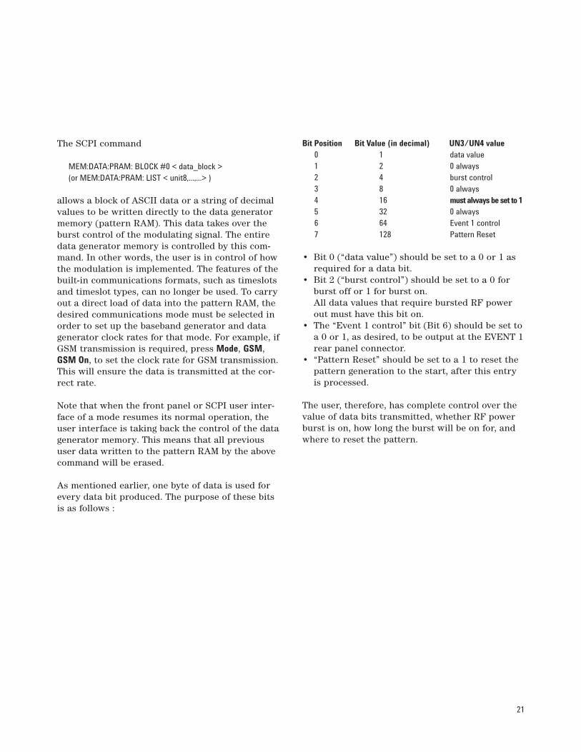
As mentioned earlier, one byte of data is used forevery data bit produced. The purpose of these bitsis as follows :
Bit Position Bit Value (in decimal) UN3/UN4 value0 1 data value1 2 0 always2 4 burst control3 8 0 always4 16 must always be set to 15 32 0 always6 64 Event 1 control7 128 Pattern Reset
• Bit 0 (“data value”) should be set to a 0 or 1 asrequired for a data bit.
• Bit 2 (“burst control”) should be set to a 0 forburst off or 1 for burst on.All data values that require bursted RF powerout must have this bit on.
• The “Event 1 control” bit (Bit 6) should be set toa 0 or 1, as desired, to be output at the EVENT 1rear panel connector.
• “Pattern Reset” should be set to a 1 to reset thepattern generation to the start, after this entryis processed.
The user, therefore, has complete control over thevalue of data bits transmitted, whether RF powerburst is on, how long the burst will be on for, andwhere to reset the pattern.

22
For example, to store a data value of 1, with burstcontrol on, the decimal value of the data would be21.
To send a fixed 4 bit repeating sequence of 1100,with burst on, the command may look like this:
MEM:DATA:PRAM:LIST 21,21,20,148
Each “block” represents the data bit and all it’sparameters, and takes up 1Byte of RAM. Note thatthe last value in the sequence, 148, sets the PatternReset bit, so that the data counters for the memorywill reset at the beginning of the 1100 sequence.
As mentioned in Section 4.2, the data bits corre-sponding to the 1326 frames in a superframe couldbe generated and loaded into the pattern RAM.There are 1250 bits in a GSM frame and therefore asuperframe contains 1.6575 Mbits. This wouldrequire 1.6575MB of RAM, when using the directload method. In order to have sufficient memoryfor generating a GSM superframe, Option UN4(which has 8MB of pattern RAM) must be installed.Unlike the custom file method, all the bits in thesuperframe must be specified - this includes guardbits, control bits and data bits. To generate a con-tinuous superframe the Pattern Reset bit should beset for the last bit in the sequence, so that the datageneration will start again at the first bit of thesuperframe.
Bit Position
Setting
Bit Value
= 21 !
16 + 4 + 1
Event 1 Burst Data
7 6 5 4 3 2 1 0
0 0 0 1 0 1 0 1
always "1"
Figure 11. Setting data values
1 Byte 1 Byte 1 Byte 1 Byte
"1" "1" "0" "0"
Pattern Reset Bit was set to '1'
0 0 0 1 0 1 0 1 0 0 0 1 0 1 0 1 0 0 0 0 0 1 0 0 1 0 0 1 0 1 0 0
21 21 20 148 etc.
Pattern Reset Bit
Figure 12. Blocks of data

23
5. Triggering a GSM FrameThere are several options available to the user totrigger a single GSM frame. These are using theTrigger key, triggering over the bus, and triggeringthe frame externally.
From the GSM mode:Select Data Format Framed.Toggle Frame Repeat Single Cont to Frame Repeat Single.Press the Frame Trigger softkey to display the rangeof options:Trigger Key
Press the front panel Trigger hardkey to outputone frame of data
BusPress this softkey to trigger the single frameover GPIB
ExternalPress this softkey to trigger a single frame froman external source. The frame triggerpulse mustbe sent to the PATTERN TRIG IN rear panelBNC input connector. The ESG-D is triggeredwhen the CMOS input transitions from low tohigh, then one frame of data is generated. Theminimum trigger input pulse width, high to low,is 100ns. The trigger edge is latched and sam-pled by falling edge of data bit clock to synchro-nize trigger with bit timing. At the end of theframe, guard bits are generated until a new trig-ger is received. If the trigger arrives too early(1.5 to 2.5 bit clock periods before the end of a
frame), it will be ignored and the next frame isdelayed until the next valid trigger occurs. If thetrigger occurs too late (between N-1.5 to N-2.5bit clocks after the frame ends), then the framebegins N bit clocks after the previous frameends. For example, if the trigger occurs between0.5 and 1.5 bit clock periods after the frameends, i.e. N=1, then 1 additional bit is insertedin between frames (i.e. next frame begins 1 bitclock period after previous frame ends). Formore information on frame and pattern triggertiming, see Section 7 of the ESG User Guide.
An application for the external frame trigger fea-ture is in GSM Base Station manufacture. The BTStransmits its timing information on the downlinkBCH, including details of the frame timing. TheBCH is used to command the mobile and tell itwhen to respond and start communication withthe BTS. In Base Station testing, the ESG-D signalgenerator (configured with the optional IQ base-band generator) can be used, simulate a mobile inorder to send a signal to the BTS to verify correctBTS operation. The ESG-D must therefore be capa-ble of starting its transmission at the correct timerelative to the BTS transmission, as would a ‘real’mobile station. To achieve this, the ESG-D can beconfigured to accept a frame trigger (setting FrameTrigger External and supplying BTS frame clock toPATTERN TRIG IN rear panel connector) from theBTS, as shown in the following diagram. This syn-chronizes the ESG-D to the BTS.
BTS
TxBTS
Rx
Frame Clock
Combiner
Pattern Trig In
RF OUTPUT
Agilent ESG-D
Figure 13. Application of external frame trigger
24
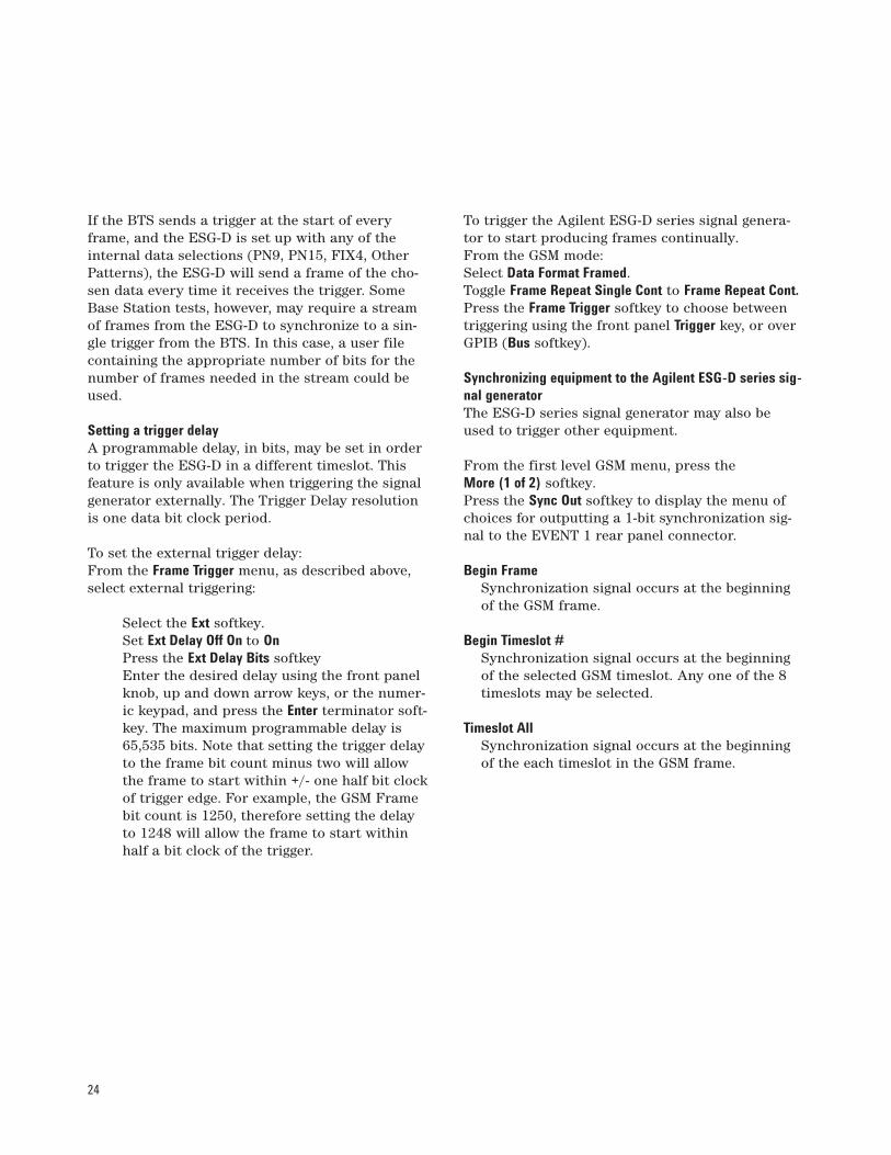
If the BTS sends a trigger at the start of everyframe, and the ESG-D is set up with any of theinternal data selections (PN9, PN15, FIX4, OtherPatterns), the ESG-D will send a frame of the cho-sen data every time it receives the trigger. SomeBase Station tests, however, may require a streamof frames from the ESG-D to synchronize to a sin-gle trigger from the BTS. In this case, a user filecontaining the appropriate number of bits for thenumber of frames needed in the stream could beused.
Setting a trigger delayA programmable delay, in bits, may be set in orderto trigger the ESG-D in a different timeslot. Thisfeature is only available when triggering the signalgenerator externally. The Trigger Delay resolutionis one data bit clock period.
To set the external trigger delay:From the Frame Trigger menu, as described above,select external triggering:
Select the Ext softkey.Set Ext Delay Off On to OnPress the Ext Delay Bits softkeyEnter the desired delay using the front panelknob, up and down arrow keys, or the numer-ic keypad, and press the Enter terminator soft-key. The maximum programmable delay is65,535 bits. Note that setting the trigger delayto the frame bit count minus two will allowthe frame to start within +/- one half bit clockof trigger edge. For example, the GSM Framebit count is 1250, therefore setting the delayto 1248 will allow the frame to start withinhalf a bit clock of the trigger.
To trigger the Agilent ESG-D series signal genera-tor to start producing frames continually.From the GSM mode:Select Data Format Framed.Toggle Frame Repeat Single Cont to Frame Repeat Cont.Press the Frame Trigger softkey to choose betweentriggering using the front panel Trigger key, or over GPIB (Bus softkey).
Synchronizing equipment to the Agilent ESG-D series sig-nal generatorThe ESG-D series signal generator may also beused to trigger other equipment.
From the first level GSM menu, press the More (1 of 2) softkey.Press the Sync Out softkey to display the menu ofchoices for outputting a 1-bit synchronization sig-nal to the EVENT 1 rear panel connector.
Begin FrameSynchronization signal occurs at the beginningof the GSM frame.
Begin Timeslot #Synchronization signal occurs at the beginningof the selected GSM timeslot. Any one of the 8timeslots may be selected.
Timeslot AllSynchronization signal occurs at the beginningof the each timeslot in the GSM frame.

25
It is also possible to move the synchronization sig-nal forward or back from the beginning of theframe or timeslot.
From the GSM first level menu, press the More (1 of 2) softkey.
Press the Sync Out Offset to set the number ofbits of offset.
Enter the desired value using the numerickeypad, the up and down arrow keys, or thefront panel knob and press the Enter termina-tor softkey. The range of allowed values is–155 through +155 bits
26
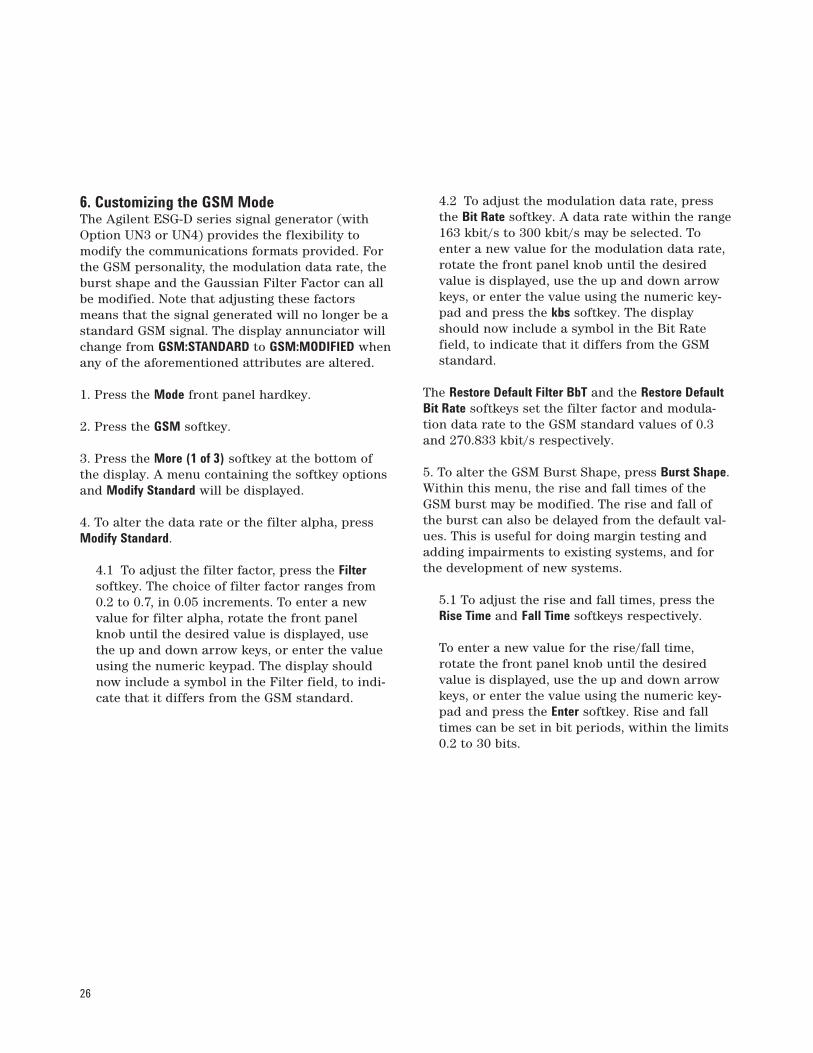
6. Customizing the GSM ModeThe Agilent ESG-D series signal generator (withOption UN3 or UN4) provides the flexibility tomodify the communications formats provided. Forthe GSM personality, the modulation data rate, theburst shape and the Gaussian Filter Factor can allbe modified. Note that adjusting these factorsmeans that the signal generated will no longer be astandard GSM signal. The display annunciator willchange from GSM:STANDARD to GSM:MODIFIED whenany of the aforementioned attributes are altered.
1. Press the Mode front panel hardkey.
2. Press the GSM softkey.
3. Press the More (1 of 3) softkey at the bottom ofthe display. A menu containing the softkey optionsand Modify Standard will be displayed.
4. To alter the data rate or the filter alpha, pressModify Standard.
4.1 To adjust the filter factor, press the Filtersoftkey. The choice of filter factor ranges from0.2 to 0.7, in 0.05 increments. To enter a newvalue for filter alpha, rotate the front panelknob until the desired value is displayed, usethe up and down arrow keys, or enter the valueusing the numeric keypad. The display shouldnow include a symbol in the Filter field, to indi-cate that it differs from the GSM standard.
4.2 To adjust the modulation data rate, pressthe Bit Rate softkey. A data rate within the range163 kbit/s to 300 kbit/s may be selected. Toenter a new value for the modulation data rate,rotate the front panel knob until the desiredvalue is displayed, use the up and down arrowkeys, or enter the value using the numeric key-pad and press the kbs softkey. The displayshould now include a symbol in the Bit Ratefield, to indicate that it differs from the GSMstandard.
The Restore Default Filter BbT and the Restore DefaultBit Rate softkeys set the filter factor and modula-tion data rate to the GSM standard values of 0.3and 270.833 kbit/s respectively.
5. To alter the GSM Burst Shape, press Burst Shape. Within this menu, the rise and fall times of theGSM burst may be modified. The rise and fall ofthe burst can also be delayed from the default val-ues. This is useful for doing margin testing andadding impairments to existing systems, and forthe development of new systems.
5.1 To adjust the rise and fall times, press theRise Time and Fall Time softkeys respectively.
To enter a new value for the rise/fall time,rotate the front panel knob until the desiredvalue is displayed, use the up and down arrowkeys, or enter the value using the numeric key-pad and press the Enter softkey. Rise and falltimes can be set in bit periods, within the limits0.2 to 30 bits.

27
Here, the rise time has been decreased from thestandard value, meaning that the power level isramped up too quickly, and the burst profile doesnot fit within the desired mask. This could causeinterference with other mobiles in the cell.
5.2 To delay the rise or fall of the GSM burst,press the Rise Delay and Fall Delay softkeysrespectively. Delay times of up to 10 bit clockperiods can be set. To enter a new value for thedelay time, rotate the front panel knob until thedesired value is displayed, use the up and downarrow keys, or enter the value using the numerickeypad and press the Enter softkey.
Here, a rise delay has been added to the burst. Ascan be seen, the burst profile is now right at thelower limit of the mask. Any further delay wouldresult in the output power level being reached toolate, and useful bits of information could be lost.
The Restore Default Burst Shape softkey restores theburst shape values to the rise/fall times of 4.22 and3.44 bit clock periods and rise/fall delays of zeroand 4.38 clock periods.
+1.0 dB
–1.0 dB
+4 dB
–6 dB
–30 dB
–70 dB
–6 dB
–30 dB
–70 dB
147 "Useful" Bits542.72µs
148 "Active" Bits, 546.42µs
3 57 1 26 1 57 310µs 8µs 10µs 10µs 10µs8µs
Pow
er
Time
Figure 14. Adjusting the rise time of a GSM TDMA power burst
+1.0 dB
–1.0 dB
+4 dB
–6 dB
–30 dB
–70 dB
–6 dB
–30 dB
–70 dB
147 "Useful" Bits542.72µs
148 "Active" Bits, 546.42µs
3 57 1 26 1 57 310µs 8µs 10µs
Rise Delay
10µs 10µs8µs
Pow
er
TimeFigure 15. Adding rise delay to a GSM TDMA power burst
28
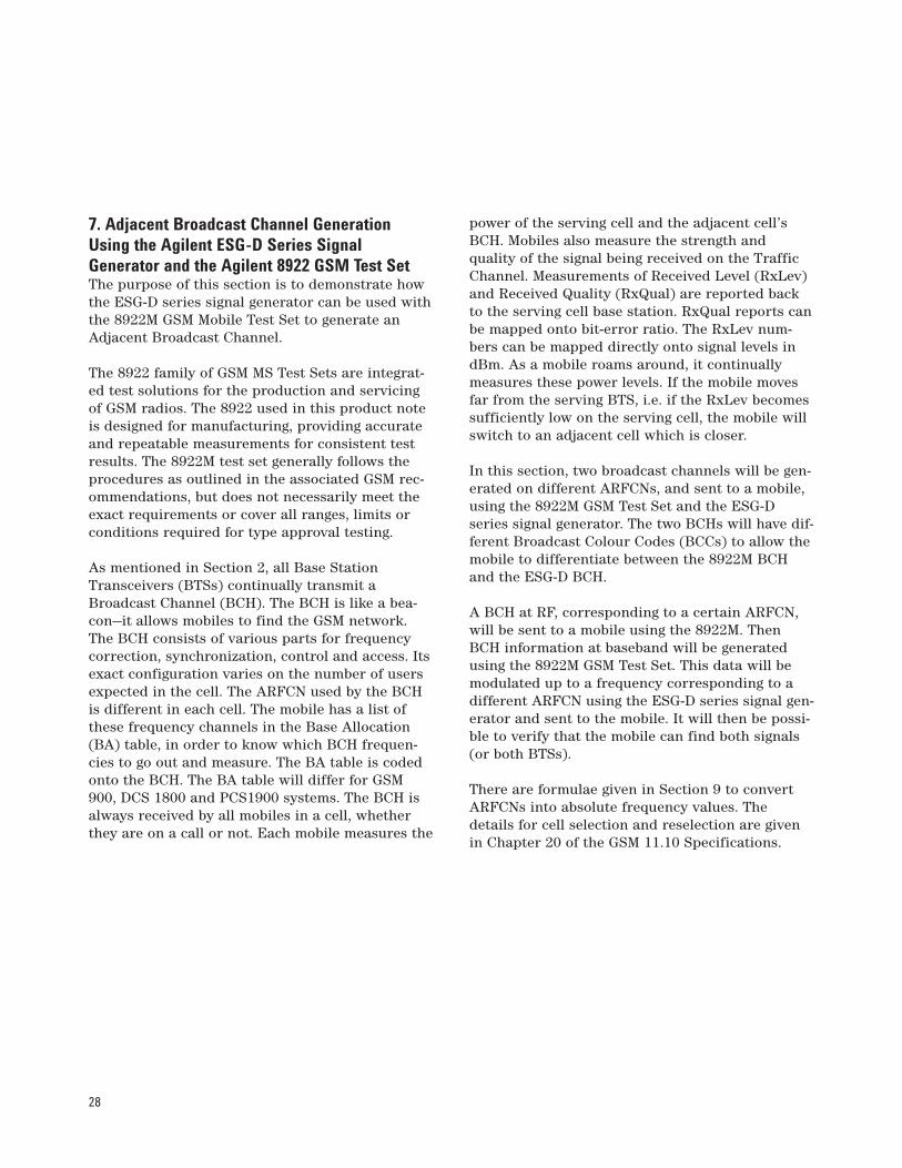
7. Adjacent Broadcast Channel GenerationUsing the Agilent ESG-D Series SignalGenerator and the Agilent 8922 GSM Test SetThe purpose of this section is to demonstrate howthe ESG-D series signal generator can be used withthe 8922M GSM Mobile Test Set to generate anAdjacent Broadcast Channel.
The 8922 family of GSM MS Test Sets are integrat-ed test solutions for the production and servicingof GSM radios. The 8922 used in this product noteis designed for manufacturing, providing accurateand repeatable measurements for consistent testresults. The 8922M test set generally follows theprocedures as outlined in the associated GSM rec-ommendations, but does not necessarily meet theexact requirements or cover all ranges, limits orconditions required for type approval testing.
As mentioned in Section 2, all Base StationTransceivers (BTSs) continually transmit aBroadcast Channel (BCH). The BCH is like a bea-con—it allows mobiles to find the GSM network.The BCH consists of various parts for frequencycorrection, synchronization, control and access. Itsexact configuration varies on the number of usersexpected in the cell. The ARFCN used by the BCHis different in each cell. The mobile has a list ofthese frequency channels in the Base Allocation(BA) table, in order to know which BCH frequen-cies to go out and measure. The BA table is codedonto the BCH. The BA table will differ for GSM900, DCS 1800 and PCS1900 systems. The BCH isalways received by all mobiles in a cell, whetherthey are on a call or not. Each mobile measures the
power of the serving cell and the adjacent cell’sBCH. Mobiles also measure the strength and quality of the signal being received on the TrafficChannel. Measurements of Received Level (RxLev)and Received Quality (RxQual) are reported backto the serving cell base station. RxQual reports canbe mapped onto bit-error ratio. The RxLev num-bers can be mapped directly onto signal levels indBm. As a mobile roams around, it continuallymeasures these power levels. If the mobile movesfar from the serving BTS, i.e. if the RxLev becomessufficiently low on the serving cell, the mobile willswitch to an adjacent cell which is closer.
In this section, two broadcast channels will be gen-erated on different ARFCNs, and sent to a mobile,using the 8922M GSM Test Set and the ESG-Dseries signal generator. The two BCHs will have dif-ferent Broadcast Colour Codes (BCCs) to allow themobile to differentiate between the 8922M BCHand the ESG-D BCH.
A BCH at RF, corresponding to a certain ARFCN,will be sent to a mobile using the 8922M. ThenBCH information at baseband will be generatedusing the 8922M GSM Test Set. This data will bemodulated up to a frequency corresponding to adifferent ARFCN using the ESG-D series signal gen-erator and sent to the mobile. It will then be possi-ble to verify that the mobile can find both signals(or both BTSs).
There are formulae given in Section 9 to convertARFCNs into absolute frequency values. Thedetails for cell selection and reselection are givenin Chapter 20 of the GSM 11.10 Specifications.

29
Connect the 8922M MS test set, the ESG-D signal genera-tor and the mobile under test
1. Connect the 8922M, ESG-D and the mobile tobe tested, as shown in Figure 16.
2. Power on the 8922M, the ESG-D series signalgenerator and the mobile.
Set up the 8922M to send broadcast data to the ESG-Dsignal generatorThe 8922M has default settings to broadcast on fre-quency channel ARFCN 20 with an amplitude of -85dBm. Different settings for these parametersmay be chosen if desired, but this will not be cov-ered in this note. Remember that the insertion lossthrough the power divider must be accounted for,as this will affect the amplitude of the signal.
3. From the front panel, press the Cell Confighardkey.
4. Go to the BA (Base Allocation) Table. This isa table that is sent to the mobile to let it knowwhich BCH ARFCNs are active in its cell. Firstof all position the cursor on the “Activated”
field, push the knob and change to “Settable”.There are 124 possible channels that can be set.Position the cursor to the top left “0” and pushthe cursor control knob.
A channel may be selected by going to thecorresponding position in the table, andsetting the value to “1”. For example, to set channel 10 for GSM,“Position” would be selected. The cursorcontrol knob would then be used to go tothe right hand column in the first row. Thisposition (for channel 10) would be select-ed, and a “1” set to activate this ARFCN.When editing is complete, “Done” and then “Activated” are selected. This tells themobile to look for a BCH on ARFCN 10.
5. Use the selection knob to go into the “AuxBCCH” menu. Select “Adjacent.”
This turns the Modulation In/Out Data andClock to OUT—the 8922M will send data to theESG-D signal generator.
POPOWERWER
Data
Clock
Power Divider (11636A)RF IN/OUT RF OUTPUT
Agilent 8922 M Agilent ESG-D10 MHz Out 10 MHz In
Figure 16. Diagram of set-up

30
Set up the Agilent ESG-D signal generator6. Press Frequency. Enter “937MHz”. This sets theadjacent signal to the frequency channel ARFCN10. Any ARFCN may be chosen, provided it isdifferent from that set on 8922M.
7. Press Ampl. Set to the power level to a valuedifferent from that on the 8922M broadcastchannel (i.e. –85dBm in the default case). Theamplitude of the signal should be larger than thesensitivity level of the mobile. For example, setthe amplitude to –100dBm. In order to take intoaccount the insertion loss through the powerdivider, enter an amplitude offset in the Amplmenu. The typical insertion loss for a powerdivider is 6.2dB, therefore the Amplitude Offsetshould be set to 6.2dBm.
8. Press Mode. Select GSMSelect Data Format PatternPress the Data softkeySelect the Ext softkey. This means that thedata from the 8922M is the modulationprovided.Turn GSM On Off to GSM On.
9. Turn RF On Off to RF On.
Check that the mobile can camp to both signals10. Slowly decrease the amplitude of the signalof the 8922M, until it is much lower than that ofthe ESG-D signal generator. The mobile shouldcamp onto the signal from the signal generatorbecause its RxLev will be better. This can be ver-ified by increasing the amplitude of signal fromthe ESG-D signal generator, and checking thatthe signal strength on the mobile’s displayincreases. Lowering the amplitude of the signalgenerator should result in the displayed mobilesignal level decreasing, until finally it will campon to the signal from the 8992M again.

31
8. Using the Agilent ESG-D Series SignalGenerator and the 8922 GSM Test Set to CarryOut GSM MS Receiver Tests The receiver measurements for radios in the GSMsystem make use Bit Error Rate (BER) techniques.A known pseudorandom binary sequence (PRBS)is transmitted to the mobile station which loopsthe received bits, after channel decoding, back tothe test equipment through its own transmitter.The BER is evaluated within the tester (such as the8922 GSM Mobile Station Test Set).
In the following sections, some key GSM measure-ments will be made using the 8922M GSM MobileStation Test Set and the ESG-D series signal gener-ator. Note that this is not a comprehensive guide tothe 8922M Test Set, nor an in-depth study of theGSM measurement specifications. For details ofthese areas, please refer to the 8922M documenta-tion and the relevant sections of the ETSI GSMspecifications.
There are formulae given in Section 14 to convertARFCNs into absolute frequency values.
8.1 Receiver co-channel rejectionCo-channel rejection measures a receiver’s abilityto receive a wanted modulated signal in the pres-ence of an unwanted modulated signal, both sig-
nals being at the same frequency. Bit error rate isthen measured to ensure the receiver is rejectingthe unwanted signal. The test is described in detailin the ETSI GSM Specifications 11.10 (Section14.4)
The ESG-D series signal generator can be used asthe unwanted source, as it provides precise0.3GMSK modulation. The wanted signal can begenerated using a test system such as the 8922MGSM MS Test Set.
Variations from the GSM 11.10 Section 11.4.4 TestRecommendations The 8922M does not use the standard test signal“C1” for the in-channel source. The standard testsignal is a 1-0 pattern with “dummy” bursts for allother timeslots of the frame. The 8922M uses a 1-0data pattern but does not transmit “dummy” burstsin all other timeslots. The 8922M cannot generate aprogress message to the mobile station. This is asignaling message instead of speech. The 8922Mdoes not simulate fading. An external fader, e.g.11759C, needs to be used with the 8922M to meetthe GSM recommendation. The 8922M and ESG-Dsignal generator cannot test the mobile station inhopped mode, because the ESG-D signal generatorcannot generate a hopping signal.
POPOWERWER
Power Divider (11636A)RF IN/OUT RF OUTPUT
Agilent 8922 M Agilent ESG-D10 MHz Out 10 MHz In
Figure 17a. Diagram of test set-up

32
Co-channel rejection measurement procedureConnect the Agilent 8922M MS Test Set, theAgilent ESG-D Signal generator and the mobileunder test as shown in Figure 17.
1. Power on all equipment BUT ensure the ESG-D signal generator has RF On Off set to RF Off
Set up the Agilent 8922M MS test set2. Preset the 8922M. Press the Preset front panelhardkey.
3. From the Cell Status Screen, use the cursorcontrol to scroll to “To Screen, More”.
4. Select “Cell Control 2”.
5. From the Cell Control 2 screen:• Under “TCH Parms” set the following:
“TCH1”Mode “Single”ARFCN “60”Check that “FS” is selected (thisshould be as it is the default set-ting)
• Select “TCH Control”• Select “TCH1 Asgn”• Highlight “Execute”• Scroll to Audio Cntl. Set “Loopback” to
“FE” (This turns Frame Erasure on)• Set “Speech” to “PRBS”• Set “PRBS Pattrn” to “10”• Set “RF Gen”, “Amplitude” to “–85dBm” as
defined in the GSM specification. (Takeinto account the insertion loss through thepower divider. For example, if the insertionloss for your power divider is 6.2dB, the“Amplitude” should be set to 78.8 dBm tocompensate for the loss. Alternatively, the
RF amplitude offset field in the 8922M I/Oconfiguration could be set to account forthe loss through the divider.)
6. Check that the mobile is camped onto the sig-nal from the 8922M.
7. Scroll to the lower right hand corner menu,and select the “BIT ERR 2” option. Under the BitError Test screen “BIT ERR 2”.
• Under “Meas Num 1”,“Type”, select“ResTypeII”.
• Under “Bits to Test”, enter the desirednumber of bits according to the GSM speci-fications (see Table 14.14 on Specifications11.10). For example, enter “2,000,000”.
• Under “Meas Num 2”, “Type”, select“ResTypeIb”.
• Under “Bits to Test”, enter the desirednumber of bits according to the GSM speci-fications (see Table 14.14 on Specifications11.10). For example, enter “3,300,000”.
• Under “MS Loopback,” “Loop Delay SpeechFrms” set to “Auto”.
Set up the Agilent ESG-D signal generator8. Press Frequency front panel hardkey. Enter“947MHz”. This sets the interfering signal to thesame frequency channel as the in-channel signal(ARFCN 60).
9. Press the Ampl front panel hardkey. Set to “-94dBm” Compensate for the insertion lossthrough the power divider by setting theAmplitude Offset to 6.2dBm. This sets the inter-ference signal to 9dB below the wanted signal,as specified in the GSM recommendations.
33
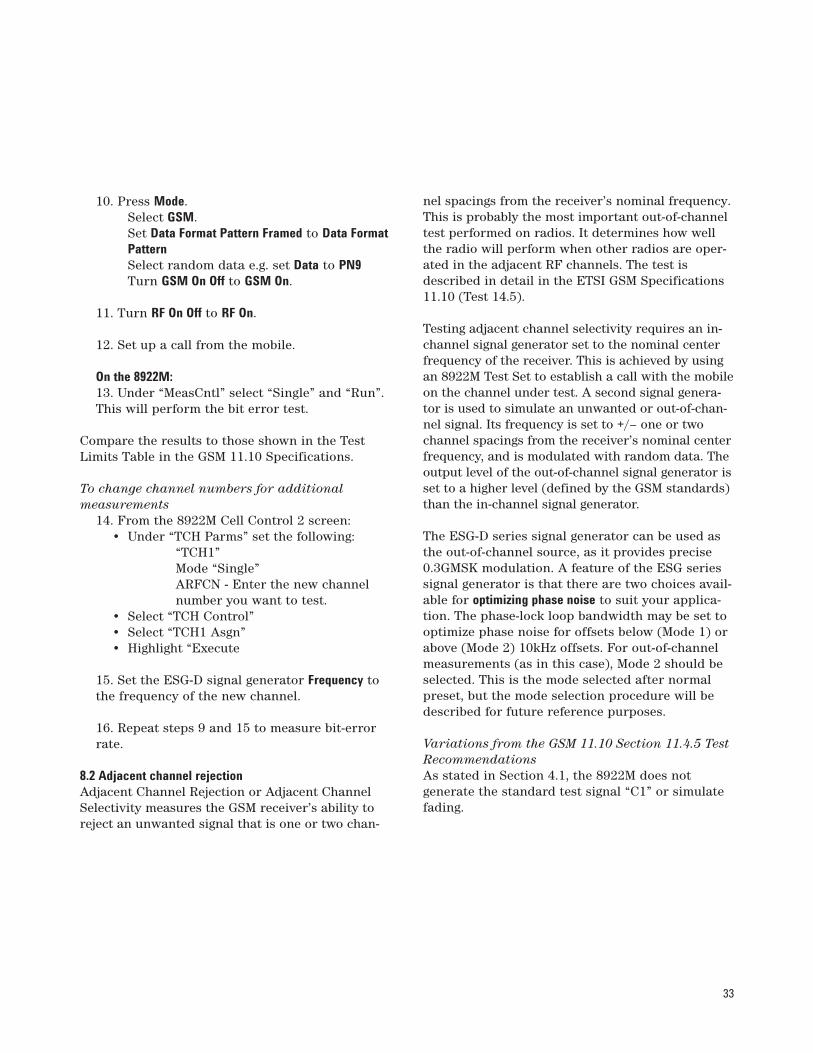
10. Press Mode. Select GSM.Set Data Format Pattern Framed to Data FormatPatternSelect random data e.g. set Data to PN9Turn GSM On Off to GSM On.
11. Turn RF On Off to RF On.
12. Set up a call from the mobile.
On the 8922M:13. Under “MeasCntl” select “Single” and “Run”.This will perform the bit error test.
Compare the results to those shown in the TestLimits Table in the GSM 11.10 Specifications.
To change channel numbers for additional measurements
14. From the 8922M Cell Control 2 screen:• Under “TCH Parms” set the following:
“TCH1”Mode “Single”ARFCN - Enter the new channelnumber you want to test.
• Select “TCH Control”• Select “TCH1 Asgn”• Highlight “Execute
15. Set the ESG-D signal generator Frequency tothe frequency of the new channel.
16. Repeat steps 9 and 15 to measure bit-errorrate.
8.2 Adjacent channel rejectionAdjacent Channel Rejection or Adjacent ChannelSelectivity measures the GSM receiver’s ability toreject an unwanted signal that is one or two chan-
nel spacings from the receiver’s nominal frequency.This is probably the most important out-of-channeltest performed on radios. It determines how wellthe radio will perform when other radios are oper-ated in the adjacent RF channels. The test isdescribed in detail in the ETSI GSM Specifications11.10 (Test 14.5).
Testing adjacent channel selectivity requires an in-channel signal generator set to the nominal centerfrequency of the receiver. This is achieved by usingan 8922M Test Set to establish a call with the mobileon the channel under test. A second signal genera-tor is used to simulate an unwanted or out-of-chan-nel signal. Its frequency is set to +/– one or twochannel spacings from the receiver’s nominal centerfrequency, and is modulated with random data. Theoutput level of the out-of-channel signal generator isset to a higher level (defined by the GSM standards)than the in-channel signal generator.
The ESG-D series signal generator can be used asthe out-of-channel source, as it provides precise0.3GMSK modulation. A feature of the ESG seriessignal generator is that there are two choices avail-able for optimizing phase noise to suit your applica-tion. The phase-lock loop bandwidth may be set tooptimize phase noise for offsets below (Mode 1) orabove (Mode 2) 10kHz offsets. For out-of-channelmeasurements (as in this case), Mode 2 should beselected. This is the mode selected after normalpreset, but the mode selection procedure will bedescribed for future reference purposes.
Variations from the GSM 11.10 Section 11.4.5 TestRecommendations As stated in Section 4.1, the 8922M does not generate the standard test signal “C1” or simulatefading.
34
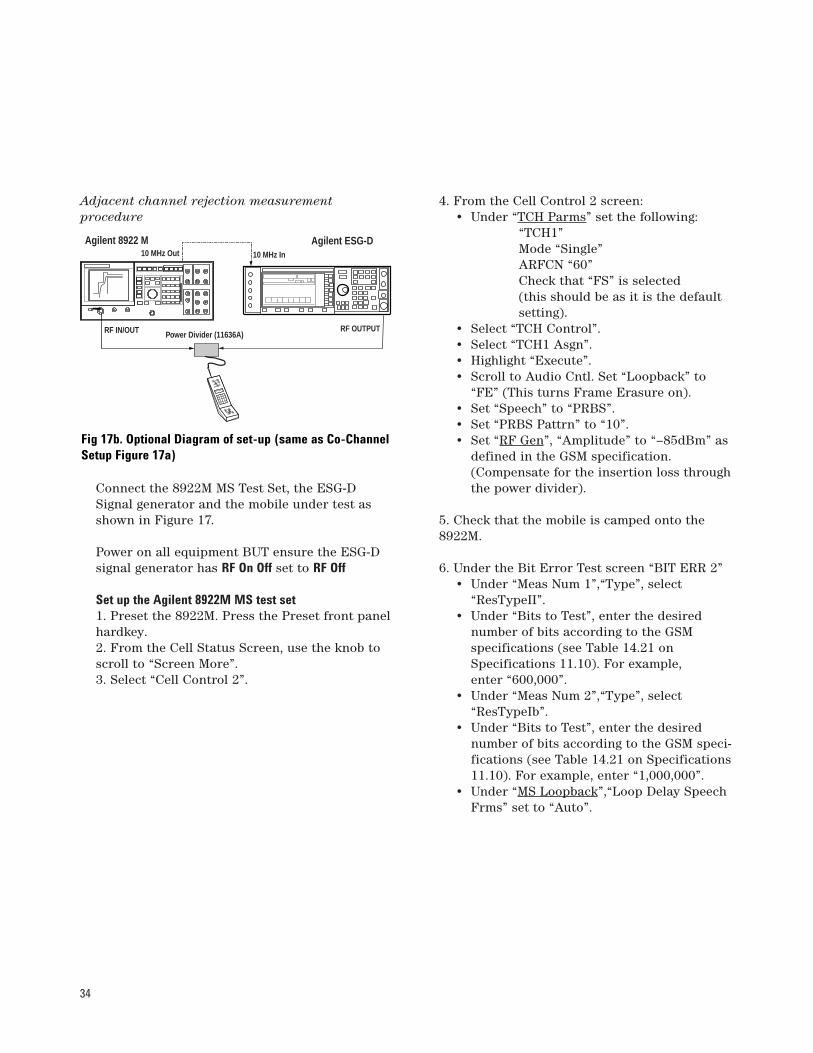
Adjacent channel rejection measurement procedure
Connect the 8922M MS Test Set, the ESG-DSignal generator and the mobile under test asshown in Figure 17.
Power on all equipment BUT ensure the ESG-Dsignal generator has RF On Off set to RF Off
Set up the Agilent 8922M MS test set1. Preset the 8922M. Press the Preset front panelhardkey.2. From the Cell Status Screen, use the knob toscroll to “Screen More”.3. Select “Cell Control 2”.
4. From the Cell Control 2 screen:• Under “TCH Parms” set the following:
“TCH1”Mode “Single”ARFCN “60”Check that “FS” is selected(this should be as it is the defaultsetting).
• Select “TCH Control”.• Select “TCH1 Asgn”.• Highlight “Execute”.• Scroll to Audio Cntl. Set “Loopback” to
“FE” (This turns Frame Erasure on).• Set “Speech” to “PRBS”.• Set “PRBS Pattrn” to “10”.• Set “RF Gen”, “Amplitude” to “–85dBm” as
defined in the GSM specification.(Compensate for the insertion loss throughthe power divider).
5. Check that the mobile is camped onto the8922M.
6. Under the Bit Error Test screen “BIT ERR 2”• Under “Meas Num 1”,“Type”, select
“ResTypeII”.• Under “Bits to Test”, enter the desired
number of bits according to the GSM specifications (see Table 14.21 onSpecifications 11.10). For example, enter “600,000”.
• Under “Meas Num 2”,“Type”, select“ResTypeIb”.
• Under “Bits to Test”, enter the desirednumber of bits according to the GSM speci-fications (see Table 14.21 on Specifications11.10). For example, enter “1,000,000”.
• Under “MS Loopback”,“Loop Delay SpeechFrms” set to “Auto”.
POPOWERWER
Power Divider (11636A)RF IN/OUT RF OUTPUT
Agilent 8922 M Agilent ESG-D10 MHz Out 10 MHz In
Fig 17b. Optional Diagram of set-up (same as Co-ChannelSetup Figure 17a)

35
Set up ESG-D signal generator7. Press Freq front panel hardkey. Enter “947.2MHz”. This sets the interfering signal to the car-rier frequency plus 200kHz (i.e. ARFCN 61). Theprocedure to select phase noise Mode 2, willnow be described.
Press the Optimize ø Noise softkey.Press the Mode 2 Optimize > 10kHz Offset softkey.
8. Press Ampl front panel hardkey. Set to“–76dBm”. Take into account the insertion lossthrough the power divider by setting AmplitudeOffset to, say, 6.2dBm. This sets the amplitude ofthe out-of-channel signal to 9dB above that ofthe in-channel signal, as specified in the GSMrecommendations.
9. Press Mode. Select GSM.Set Data Format Pattern Framed to Data FormatPattern.Select a random data pattern. Set Data, PN9.Turn GSM On Off to GSM On.
10. Turn RF On Off to RF On.
11. Set up a call from the mobile.
On the 8922M:12. Under “MeasCntl” select “Single” and “Run”.This will perform the bit error test.
Compare the results to those shown in the TestLimits Table in the GSM 11.10 Specifications.
To change the frequency of the out-of-channel signal13. Toggle to RF Off.
14. Set the ESG-D series signal generatorFrequency to 946.8 MHz (carrier frequency minus200 kHz).
15. Repeat steps 9-12 to measure bit-error rate.
16. Set the ESG-D series signal generatorFrequency to 947.4 MHz (carrier frequency plus400 kHz).
17. Set the ESG-D signal generator Amplitude to–44dBm. This sets the amplitude of the out-of-channel signal to 41dB above that of the in-channel signal, as stated in the GSM recommen-dations.
18. Repeat steps 9-12 to measure bit-error rate.
19. Set the ESG-D series signal generatorFrequency to 946.6 MHz (carrier frequency minus400 kHz).
20. Repeat steps 9-12 to measure bit-error rate.
8.3 Receiver intermodulation rejectionIntermodulation rejection measures a receiver’sability to receive a wanted modulated signal in thepresence of two or more unwanted signals thathave a specific frequency relationship to the want-ed signal’s frequency. The primary source of inter-modulation signals includes filters, mixers, andamplifiers in the RF front end of the GSM mobilephone. The test is described in detail in the ETSIGSM Specifications 11.10 (Section 14.6).
The two interfering signals are a GMSK-modulatedsignal carrying PRBS information and an unmodu-lated carrier. The modulated signal is operated at afrequency offset of eight channels and the unmodu-lated signal at an offset of four channels above thedesired signal. The level of the desired signal is at4dB above the reference sensitivity level. The levelsof the interfering signals depend on the class ofmobile station being tested.

36
The in-channel signal can be generated using a testsystem such as the 8922M GSM Test Station. TheESG-D series signal generator can be used as themodulated interference source, as it provides pre-cise 0.3GMSK modulated random data. The secondinterference signal can also be provided by an ESGseries signal generator without option UN3/UN4,as only an unmodulated signal is required.
Variations from the GSM 11.10 Section II.4.6 TestRecommendations As in stated in Section 4.1, the 8922M does not usethe standard test signal “C1” for the in-channelsource.
Intermodulation rejection measurement procedure
Connect the 8922M MS Test Set, the ESG seriessignal generators and the mobile under test asshown in Figure 18.1. Power on all equipment BUT ensure the ESGsignal generators have RF On Off set to RF Off.
Set up the 8922M MS Test Set2. Preset the 8922M. Press the Preset front panelhardkey.
3. From the Cell Status Screen, use the knob toscroll to “Screen, More”.4. Select “Cell Control 2”. 5. From the Cell Control 2 screen:
• Under “TCH Parms” set the following:“TCH1”Mode “Single”ARFCN “60”Check that “FS” is selected (itshould be as this is the default setting).
• Select “TCH Control”.• Select “TCH1 Asgn”.• Highlight “Execute”. • Scroll to Audio Cntl. Set “Loopback” to
“FE” (This turns Frame Erasure on).• Set “Speech” to “PRBS”.• Set “PRBS Pattrn” to “10”.• Set “RF Gen”, “Amplitude” to “–85dBm” as
defined in the GSM specification.(Compensate for the insertion loss throughthe power divider, typically 6.2dB).
6. Make a call from the mobile to the 8922M.
POPOWERWER
Divider
RF IN/OUTRF OUTPUT
RF OUTPUT
Agilent 8922 M Agilent ESG-D
ESG
10 MHz Out10 MHz In
10 MHz In
Figure 18.

37
7. Change “RF Gen”, “Amplitude” to a level 4dBabove the reference sensitivity as defined in theGSM specification. The reference sensitivitylevel will depend on the type of mobile used(–98dBm for small MS and –100dBm for otherMS types). Remember to compensate for theinsertion loss through the power divider.
8. Under the Bit Error Test screen “BIT ERR 2”• Under “Meas Num 1”,“Type”, select
“ResTypeII”.• Under “Bits to Test”, enter the desired
number of bits according to the GSM speci-fications (see Table 14.14 on Specifications11.10). For example, enter “8200”.
• Under “Meas Num 2,” “Type”, select“ResTypeIb”.
• Under “Bits to Test”, enter the desirednumber of bits according to the GSM speci-fications (see Table 14.14 on Specifications11.10). For example, enter “8200”.
• Under “MS Loopback,” “Loop Delay SpeechFrms” set to “Auto”.
Set up the Agilent ESG signal generator for the first (unmodulated) interference source9. Press Frequency. Enter “947.8 MHz”. This setsthe interfering signal to an ARFCN four frequen-cy channels above the in-channel signal (ARFCN64).
10. Press Ampl. Set according to GSM recommen-dations (–49dBm for a snall MS and –39dBm forother MS. DCS1800 mobiles require differentpower levels—refer to Table 14-23 in the GSM11.10 specifications) Take into account theinsertion loss through the power divider by setting Amplitude Offset to, say, 6.2dBm).
11. Turn RF On Off to RF On.
Set up the ESG-D signal generator for the second mod-ulated interference source12. Press Frequency. Enter “948.6 MHz”. This setsthe interfering signal to an ARFCN eight fre-quency channels above the in-channel signal(ARFCN 68).
13. Press Ampl. Set to according to GSM recom-mendations (–50 dBm for GSM900 mobiles. For DCS1800 mobiles, please refer to table 14-23in the ETSI GSM 11.10 specifications). Again, compensate for the insertion loss throughthe power divider, by setting Amplitude Offset.
14. Press Mode. Select GSM.Set Data Format Pattern Framed to Data FormatPattern.Select a random data pattern. Set Data,PN9.Toggle GSM On Off to GSM On.
15. Turn RF On Off to RF On.
16. Make a call from the mobile.
On the 8922M:17. Under “MeasCntl” select “Single” and “Run”.This will perform the bit error test.
Compare the results to those shown in the TestLimits Table for Intermodulation Rejection in theGSM 11.10 Specifications.
38
To change frequencies of interfering signals18. Repeat Steps 11-19 with the first interferingsignal 4 ARFCNs below the wanted signal, andthe second interfering signal 8 ARFCNs belowthe wanted signal. Do this using the Frequencysoftkey on both ESG signal generators.
To change channel numbers for additional measurements.
Follow steps 16-18 in Section 4.1 “Receiver Co-Channel Rejection”.
ARFCN Absolute Radio Frequency ChannelNumber

39
9. Translating ARFCN into Absolute FrequencyValues for GSM SystemsSome GSM users prefer to work in terms of channelnumbers (ARFCNs) rather than absolute frequen-cies. Here are some formulae to convert ARFCNs tothe corresponding absolute frequencies.
Primary GSM:
Uplink: Ful(n) = 890.0 MHz + (0.2 MHz) . n
and
Downlink: Fdl(n) = Ful(n) + 45MHz
where
n = ARFCN, 1 ≤ n ≤124
E-GSM:
Uplink: Ful(n) = 890.0 MHz + (0.2 MHz) . n
where
n = ARFCN, 0 ≤ n ≤124
and
Ful(n) = 890.0 MHz + (0.2 MHz) . (n-1024)
where
n = ARFCN, 975 ≤ n ≤ 1023
and
Downlink: Fdl(n) = Ful(n) + 45MHz
DCS 1800:
Uplink: Ful(n) =1,710 MHz + (0.2 MHz) . (n -511)
and
Downlink: Fdl(n) = Ful(n) + 95MHz
where
n = ARFCN, 512 ≤ n ≤ 885
PCS1900:
Uplink: Ful(n) =1850 MHz + (0.2 MHz) . (n -512)
and
Downlink: Fdl(n) = Ful(n) + 80MHz
where
n = ARFCN, 512 ≤ n ≤ 810

40
10. Glossary of TermsBA Base AllocationBCC Broadcast Colour CodeBCCH Broadcast Control ChannelBCH Broadcast ChannelBER Bit Error RateBSC Base Station ControllerBSS Base Station SystemBTS Base Transceiver Station
CCCH Common Control ChannelCRC Cyclic Redundancy Check
DECT Digital Enhanced CordlessTelecommunications
ETSI European TelecommunicationsStandards Institute
FCH Frequency ChannelFDMA Frequency Division Multiple Access
GSM Global System for MobileCommunications
GMSK Gaussian Minimum Shift Keying
I/Q In phase/Quadrature
MS Mobile Station
NADC North American Dual ModeCellular system
PCS Personal Communications SystemPHS Personal Handyphone SystemPDC Personal Digital Cellular SystemPRBS Pseudo-random Binary Sequence
RF Radio FrequencyRxLev Received Signal Level
SACCH Slow Associated Control ChannelSCH Synchronization ChannelSDCCH Standalone Dedicated Control
Channel
TCH Traffic ChannelTDMA Time Division Multiple AccessTETRA Trans European Trunked RadioTS Time SlotTX/RX Transmit/Receive Channels
(uplink/downlink)Type Ia Error corrected and CRC protected
bitsType Ib Error corrected bitsType II Non-error corrected bits
The following table shows a summary of the speci-fications for the digital communications standardsprovided with Options UN3 and UN4.

41
11. Specifications
1 PDC ACP measurements reflect performance in the 1400 to 1500 frequency band, at offset or 50 and 100 kHz. 2 Specifications apply for the frequency range, data rates and filter factors (a or BbT) specified for each standard and at power levels ≤+ 7 dBm (≤+ 4 dBm for TETRA). 3 ACP for TETRA is measured over a 25 kHz bandwidth, with an 18 kHz root raised cosine filter applied. 4 The ‘channel spacing’ determines the offset size of the adjacent and alternate channels: Adjacent Chan. offset = 1 x channel spacing, 1st Alt. Chan.= 2 x channel spacing, 2nd
Alt. Chan. = 3 x channel spacing, etc.
NADC PDC PHS TETRA DECT GSM (DCS, PCS)
Modulation Format GFSK GMSK
Data Rate 48.6 42 384 36 1,152 270.83(default, kbits/sec) Adjustment Range 40 to 75.5 40 to 75.5 320 to 605 31 to 37.8 922 to 1209.6 163 to 300(kbits/sec)
Filter Default Value � = 0.35 � = 0.5 � = 0.5 � = 0.35 BbT = 0.5 BbT = 0.3
Range (a or BbT) 0.3, 0.35, 0.4, 0.5, 0.6 0.2 to 0.7 in .05 dB steps
Error Vector Magnitude2 Cont. / Burst Cont. / Burst Cont. / Burst Cont. / Burst N/A N/A (% rms)
Low EVM Mode 1.25 1.75 1.25 1.75 1.5 1.75 1.25 2.0 Low EVM Mode (typical) 0.8 1.25 0.8 1.25 0.9 0.9 0.8 1.25 Low ACP Mode (typical) 1.5 1.75 1.25 1.25 1.25 1.25 3.25 3.25
Global Phase Error1 N/A N/A N/A N/A N/A 1˚/4˚0.5˚/(rms/pk) 1.75˚ (typ.)
Deviation Accuracy1 (kHz) N/A N/A N/A N/A 6 (1.5, typical) N/A
Channel Spacing (kHz) 30 50 300 25 1728 200
Adjacent Channel Power1 Cont./Burst Cont./Burst Cont./Burst Cont./Burst3 N/A Cont. / Burst(ACP)(Low ACP Mode,dBc, typical) at Adjacent Channel4 –34 –34 --- --- –68 –65 –37 –37 at 1st Alternate Channel3 –75 –72 –72 –70 –76 –76 –77 –76 –71 –69 at 2nd Alternate Channel3 –77 –76 --- –78 –78 –79 –78 –81 –79 at 3rd Alternate Channel3 –79 –78 –78 –78 --- –79 –79 –83 –81
Supported Burst Types Custom, Custom, Custom, Custom, Custom, Custom,Up/Down Up/Down TCH, Up Contrl 1&2, Dummy B Normal, FCorr,TCH TCH Sync Up Normal, 1&2, Sync, Dummy,
Up Vox Down Normal, Traffic B, Access Down Sync Low Capacity
Scramble Capabilities Yes Yes
Related Literature Pub. Number
ETSI GSM/DCS Technical Specifi-cations, ETSI Secretariat, 06921, Sophia Antipolis Cedex, Valbonne, France.
An Introduction to GSM, Siegmund M Redl, Matthias K Weber, Malcolm
W Oliphant, 1995, Artech House Publishers ISBN 0-89006-785-6
Agilent ESG Series RF Signal 5965-3096EGenerators, Data Sheet
Agilent ESG Series Synthesized Signal 5965-4973EGenerators, Configuration Guide
Flexibility and Performance - 5965-3095EAgilent ESG Series Digital and Analog RF Signal Generators
Evolving with your measurements 5965-7158Eneeds - the enhanced Agilent ESG series RF signal generators provide additional performance, PhotoCard
GSM Mobile Test Solutions, Data 5964-6586ESheet for the Agilent 8922S, 8922M and 8320E GSM/DCS/PCS mobile test sets
Pub. Number
GSM900 & DCS1800 Transmitter 5962-9942ETesting, White Paper
An introduction to digital modulation 5965-7160Eas used in communications systems
Signal Generator Selection Guide 5965-3094E
IntuiLink Software, Data Sheet 5980-3115EN
Generating and Downloading Data 5966-1010Eto the ESG-D RF Signal Generator for Digital Modulation, Product Note
Customize Digital Modulation with 5966-4096EESG-D Series Real-Time IQ Baseband Generator, Option UND, Product Note
Multi-channel CDMA Personality 5968-2981Efor Component Test, Option UN5, Product Note
Generating Digital Modulation with 5966-4097Ethe ESG-D Series Dual Arbitrary Waveform Generator, Option UND, Product Note
42

Agilent Technologies’ Test and Measurement Support, Services, and AssistanceAgilent Technologies aims to maximize the value you receive,while minimizing your risk and problems. We strive to ensurethat you get the test and measurement capabilities you paid for and obtain the support you need. Our extensive supportresources and services can help you choose the right Agilentproducts for your applications and apply them successfully.Every instrument and system we sell has a global warranty.Support is available for at least five years beyond the produc-tion life of the product. Two concepts underlie Agilent’s overall support policy: “Our Promise” and “Your Advantage.”
Our Promise“Our Promise” means your Agilent test and measurement equip-ment will meet its advertised performance and functionality.When you are choosing new equipment, we will help you withproduct information, including realistic performance specifica-tions and practical recommendations from experienced testengineers. When you use Agilent equipment, we can verify thatit works properly, help with product operation, and providebasic measurement assistance for the use of specified capabili-ties, at no extra cost upon request. Many self-help tools areavailable.
Your Advantage“Your Advantage” means that Agilent offers a wide range of additional expert test and measurement services, which you can purchase according to your unique technical and businessneeds. Solve problems efficiently and gain a competitive edge by contracting with us for calibration, extra-cost upgrades, out-of-warranty repairs, and on-site education and training, as well as design, system integration, project management, and otherprofessional services. Experienced Agilent engineers and tech-nicians worldwide can help you maximize your productivity,optimize the return on investment of your Agilent instrumentsand systems, and obtain dependable measurement accuracy for the life of those products.
Get assistance with all your test and measurement needs at: www.agilent.com/find/assist
Product specifications and descriptions in this document subject to change without notice.
Copyright © 1997, 2000, 2001 Agilent TechnologiesPrinted in U.S.A. May 29, 20015965-7158E