product information report frl selection · product information report. frl selection. overview....
TRANSCRIPT
(1 of 6)
Copyright © 2014 Lawson Products, Inc. All rights reserved. Printed in U.S.A. (Rev. 05/18)
Product Information ReportFRL Selection
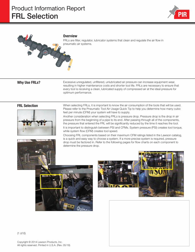
OverviewFRLs are filter, regulator, lubricator systems that clean and regulate the air flow in pneumatic air systems.
Why Use FRLs? Excessive unregulated, unfiltered, unlubricated air pressure can increase equipment wear, resulting in higher maintenance costs and shorter tool life. FRLs are necessary to ensure that every tool is receiving a clean, lubricated supply of compressed air at the ideal pressure for optimum performance.
FRL Selection When selecting FRLs, it is important to know the air consumption of the tools that will be used. Please refer to the Pneumatic Tool Air Usage Quick Tip to help you determine how many cubic feet per minute (CFM) your system will have to supply.Another consideration when selecting FRLs is pressure drop. Pressure drop is the drop in air pressure from the beginning of a pipe to its end. After passing through all of the components, the pressure that entered the FRL will be significantly reduced by the time it reaches the tool.It is important to distinguish between PSI and CFMs. System pressure (PSI) creates tool torque, while system flow (CFM) creates tool speed.Choosing FRL components based on their maximum CFM ratings listed in the Lawson catalog, is a quick and easy way to choose a system. If a more precise system is required, pressure drop must be factored in. Refer to the following pages for flow charts on each component to determine the pressure drop.

(2 of 6)
Product Information ReportFRL Selection
Filter Selection Flow Charts
After determining the CFM requirements of the system, refer to the flow charts below and select filter pipe size by choosing the curve that offers minimum pressure drop at desired flow in CFM.
How To Read Flow ChartsTo read the flow charts, first determine the inlet pressure that will be used. Each graph contains three pressure curves. Find the appropriate flow you need on the horizontal plane. Find the intersection of the pressure curve and the CFM flow. Follow a horizontal path to find the pressure loss. If the pressure drop is out of the 2 to 5 PSIG range, select a different port size.
Filters Air filters are designed to remove airborne solid contaminants, pipe scale, rust, pipe dope, etc., which may plug small orifices or cause excessive wear and premature failure of pneumatic components.
AC
B
1/4" Port 3/8" Body
3/8" Port 3/8" Body
1/2" Port 1/2" Body
3/4" Port 1" Body
1" Port 1" Body

(3 of 6)
Product Information ReportFRL Selection
Coalescing Filter Flow Charts
How To Read Flow ChartsTo read the flow charts, first determine the inlet pressure that will be used. Each graph contains three pressure curves. Find the appropriate flow on the horizontal plane. Find the intersection of the pressure curve and the CFM flow. Follow a horizontal path to find the pressure loss. If the pressure drop is out of the 2 to 5 PSIG range, select a different port size.
1/4" Port 1/8" Body
1/4" Port 3/8" Body
3/8" Port 3/8" Body
1/2" Port 1/2" Body
Coalescing Filters Coalescing filters are designed to remove aerosol particulates that are too small for a standard filter to capture. These filters provide oil-free air for applications such as spray painting, air gauging, pneumatic instrumentation, printing and packaging. Coalescing filters are designed to be used in conjunction with standard filters and are not designed to replace them.
A
C
B

(4 of 6)
Product Information ReportFRL Selection
A
C
B
Regulators Regulators govern line pressure changes and deliver a constant outlet pressure to the downstream air components. Lawson offers a rolling diaphragm style regulator, which offers a long service life and excellent accuracy.
Regulator Flow Charts First determine the output pressure you need. Find the appropriate curve on the chart. Follow the curve until it intersects with the desired flow. The drop in the curve represents the pressure drop. In order to reach the desired pressure, you must add the pressure drop.
1/4" Port3/8" Body
3/8" Port3/8" Body
3/4" Port1" Body
1/4" Port1/8" Body
1" Port1" Body
3/8" Port1/2" Body

(5 of 6)
Product Information ReportFRL Selection
Lubricators Many pneumatic system components and almost all pneumatic tools perform better when lubricated with oil. Lubricators inject an oil mist into the airstream to lubricate downstream air equipment for reduced friction and wear.
A
C
B
First determine the inlet pressure that will be used. Each graph contains three pressure curves. Find the appropriate flow on the horizontal plane. Find the intersection of the pressure curve and the CFM flow. Then follow a horizontal path to find the pressure drop. A pressure drop of 2 to 5 PSI is ideal. If the pressure drop is out of the 2 to 5 PSIG range, select a different port size.
Lubricator Flow Charts
1/4" Port 3/8" Body
1/2" Port 1/2" Body
3/8" Port 3/8" Body
3/4" Port 1" Body
1" Port 1" Body

(6 of 6)
Product Information ReportFRL Selection
FRL Installation and Maintenance Recommendations
• Always have an FRL installed into the air line just before the point of use for an air tool.• Install a safety lockout valve before the filter for quick, local shut off of the air supply.• Install an excess flow safety check valve after the FLR to prevent hose whip and injury.• Each tool should have a lead-in hose so that connection and disconnection is at least 18"
from the handle of the tool. This will extend the life of the coupler and nipple.• Polycarbonate bowls are suitable for use in normal industrial environments, but should not
be located in areas where they could be subjected to direct sunlight, an impact blow or temperatures above 125°F (51.5°C).
• Metal bowls can resist the effects of most solvents but should not be subjected to salt-laden atmospheres or used where strong acids or bases are present. Metal bowl guards are recommended for all applications to help protect a polycarbonate bowl from damage.
Typical Pneumatic Setup (Ceiling View)
1 Primary Filter and/or Refrigerated Drier
2 Main Safety Lockout
3 Drip Leg with 150 PSI Drain Cock
4 Local Safety Lockout
5 Filter
6 Coelescing Filter
7 Regulator at 90 PSI
8 Excess Flow Check Valve
9 Safety Coupler
10 Paint Spray Gun
11 Lubricator
12 Air Tool
13 Blow Gun
14 Manifold Block
15 Filter/Regulator Combo Unit
16 Swing Coupler
17 Lead-In Hose
18 Swivel Coupler