product design and manufacturing process based ontology
TRANSCRIPT
J Intell ManufDOI 10.1007/s10845-016-1290-2
Product design and manufacturing process based ontologyfor manufacturing knowledge reuse
Peter Chhim1 · Ratna Babu Chinnam1 · Noureddin Sadawi2
Received: 10 April 2016 / Accepted: 15 December 2016© Springer Science+Business Media New York 2017
Abstract This paper presents an effective product designand manufacturing process based ontology for manufactur-ing knowledge reuse. While a number of related efforts existin the literature, there lacks a granular, interconnected prod-uct design and manufacturing process based ontology thatcan lead to greater industry adoption and knowledge reuse.In particular, the proposed ontology leverages an establishedindustry standard to connect product design and manufactur-ing process knowledge in a logical and effective manner. Theresulting effort is a general ontological framework that can bewidely employed by the manufacturing industry. Addition-ally, the feasibility of implementing the ontology enabledknowledge reuse framework is demonstrated through a real-world case study.
Keywords APQP · Knowledge management ·Manufacturing ontology · Semantic web · SPARQL
Introduction
In an increasingly globalized world where competitionadvances at a fierce pace, the strategicmanagement of knowl-edge continues to be a significant topic for organizations. Ina 2014 survey conducted by the Technology Services Indus-try Association, nearly 60% of respondents indicated they
B Ratna Babu [email protected]
1 Industrial and Systems Engineering Department, Wayne StateUniversity, Detroit, MI 48202, USA
2 Department of Surgery and Cancer, Imperial College London,South Kensington Campus, London SW7 2AZ, UK
planned to invest in knowledge management (KM) (TSIA2014). Within the manufacturing industry, researchers havepointed to growing information complexity (Lin et al. 2011),inconsistent terminology (Lin and Harding 2007; Lin et al.2011), insufficient information retrieval tools (Iyer et al.2005), and a lack of widely accessible knowledge reposito-ries (Chandrasegaran et al. 2013) as significant challenges toknowledge sharing. As a result, knowledge reuse within thisdomain has been found to be considerably low. In a studyconducted by Ettlie and Kubarek (2008), knowledge reusewas being adopted only 28% of the time for manufacturingapplications! Further complicating matters is the globaliza-tion of manufacturing and the massive challenges associatedwith sharing distributed knowledge among various culturesand levels of expertise (Desouza and Evaristo 2003). For-tunately organizations can turn to ontologies as an effectivemeans to address these issues, largely in part for their abilityto promote information sharing within a particular domain(Swartout et al. 1996; Noy and McGuinness 2001; Lin andHarding 2007).
Research objective
Our research focus is on promoting reuse of knowledgeresulting from Design Failure Mode and Effects Analysis(DFMEA) and Process Failure Mode and Effects Analy-sis (PFMEA) processes in the manufacturing industry. Inparticular, the research proposes the development of an ontol-ogy that is informed by a mature industry standard andconnects key concepts between product design and manu-facturing process knowledge at a granular, yet actionablelevel for the effective reuse of knowledge. The research
123
J Intell Manuf
extends existing ontological efforts from the manufacturingfailuremode domain, e.g. Lee (2001), Dittmann et al. (2004),Laaroussi et al. (2007), Ebrahimimpour et al. (2010), Mol-hanec et al. (2011) and Zhao and Zhu 2012. Here, whileexisting efforts undoubtedly contribute to the domain, theytend to focus solely on manufacturing process failures andlack rich connectivity with pertinent manufacturing processcontrols, and upstream design knowledge. The lack of con-nection to upstream design knowledge is a key omissiongiven engineering design knowledge is inextricably linkedto downstream manufacturing processes. For example, if adesign engineer provides a product specification that is notinformed by the manufacturability of said specification, aproduct failure may occur. While this may seem surprising,these silo-based approaches are not uncommon and are con-sistent with the traditional method of information sharingwhere the use of a single schema is commonly employed(Hoffman and Joan-Arinyo 1998).
Additionally, the adoption of these ontologies withinindustry is limited by a lack of connection to industry rel-evant terminology. As Chandrasekaran et al. (1999) indicate,utilizing a familiar industry standard terminology appeals to abroader audience and hence is more adequate in representingthe vocabulary of the domain (Chandrasekaran et al. 1999).Lin et al. (2004) echo this sentiment in that the knowledgewithin an ontology needs to be explicit in a well-defined ter-minology accepted by all stakeholders. Hence, the researchturns to the widely adopted Advanced Product Quality Plan-ning (APQP) process of the automotive industry to identifythe terms and relationships necessary to inform the ontology.The process is used upfront during the design and launch ofa product and captures key concepts and associated activitiesfrom both the design and manufacturing process domains.Additionally, it is a mature process that has been in practicefor over 20years (AIAG2008), and that reachesmanypeople.In the US alone, it is estimated that over 1.7 million peopleare employed in the designing, engineering, manufacturingand supplying of parts and components (Hill et al. 2016).Given most of the existing work on ontologies is comprisedof textual definitions of concepts and terms (Young et al.2007), thismakes themsusceptible tomultiple interpretations(Chungoora et al. 2013) and ambiguities when defining thesemantics of concepts (Imran and Young 2015). By employ-ing thismature and familiar process,we seek tomitigate theseconcerns and contribute to what Ameri and Patil (2012) haveindicated are still the early stages of ontological manufactur-ing information modeling. Lastly, but not to be overlooked,the proposed framework addresses the utilization aspect ofan ontology. This is in contrast to most other offerings in theliterature that omit or gloss over this key activity. Finally, weemploy a real world case study to demonstrate the feasibil-ity of implementing our ontology enabled knowledge reuseframework.
Methodology: knowledge representation throughontologies and semantic web technologies
Knowledge representation has been identified as describingthe status of the world (Brachman and Levesque 1986). Anincreasing popular form of knowledge representation is anontology. Here, we provide Borst’s (1997) definition of anontology as an ‘explicit formal specification of a shared con-ceptualization’. A simplistic translation of this definition isthat ontologies represent consensual, explicit knowledge ina machine-readable manner. Ontologies can be increasinglyfound in avariety offields including the aforementionedman-ufacturing failure mode domain.
Many languages exist for the implementation of ontolo-gies. A thorough review within the manufacturing field ispresented by Negri et al. (2016). A key enhancement to theutilization of ontologies is the Semantic Web. Here, specificefforts have occurred to improve the connectivity, sharing andreuse of data across applications, enterprises and communityboundaries. As Iarovy et al. (2015) indicate, web based stan-dards are more prominent than traditional languages becausethey provide better interoperability between heterogeneoussystems.As recommendedbyNegri et al. (2016), the researchutilizes OWL as the manufacturing systems ontology lan-guage. This is in large part because of its ability to meet thefour main requirements for semantic language representa-tion of the manufacturing domain, i.e., support conceptualmodeling and data storage, ease of use and maintenance,interoperability, and automated reasoning (Negri et al. 2016).Moreover, OWL based ontologies can incorporate Seman-tic Web Rule Language (SWRL) rules that allow reasoningengines to infer new facts not already contained in the model(Iarovy et al. 2015). Finally, given OWL is based upon aResource Description Framework (RDF) meta data model,SPARQL Protocol and RDF Query Language (SPARQL) isused as the query language to obtain data from the ontology(Ducharme 2013).
Additionally, SPARQLallows for federated queries acrossdiverse data sources through the use of different SPAPRLendpoints. This ability increases the usefulness of the infor-mation obtained (Fabian et al. 2012) by connecting throughother pertinent sources.
Advanced product quality planning: foundationfor ontology development
APQP is a structuredmethod for defining and establishing thenecessary steps to ensure that a product is planned, designed,manufactured and launched effectively to satisfy customerneeds (Bobrek and Sokovic 2005). It was collectively devel-oped by U.S. automakers Chrysler, Ford Motor Company,and General Motors to communicate product quality plan-
123
J Intell Manuf
Fig. 1 The five phases of the APQP process (Bobrek and Sokovic 2005)
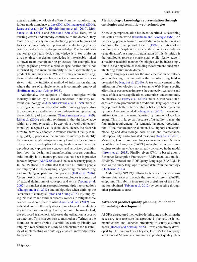
ning requirements to their supply base, and was released viaa common reference manual in July 1994 (Thisse 1996).Essentially, the goal of APQP is to facilitate communica-tion with all parties involved to ensure that required stepsare completed correctly and on time (Bobrek and Sokovic2005). The APQP process consists of five phases (AIAG2008): (1) Planning and Defining the Program, (2) ProductDesign and Development, (3) Process Design and Develop-ment, (4) Product and Process Validation, and (5) Feedback,Assessment andCorrectiveAction.Visually, these phases areshown in Fig. 1.
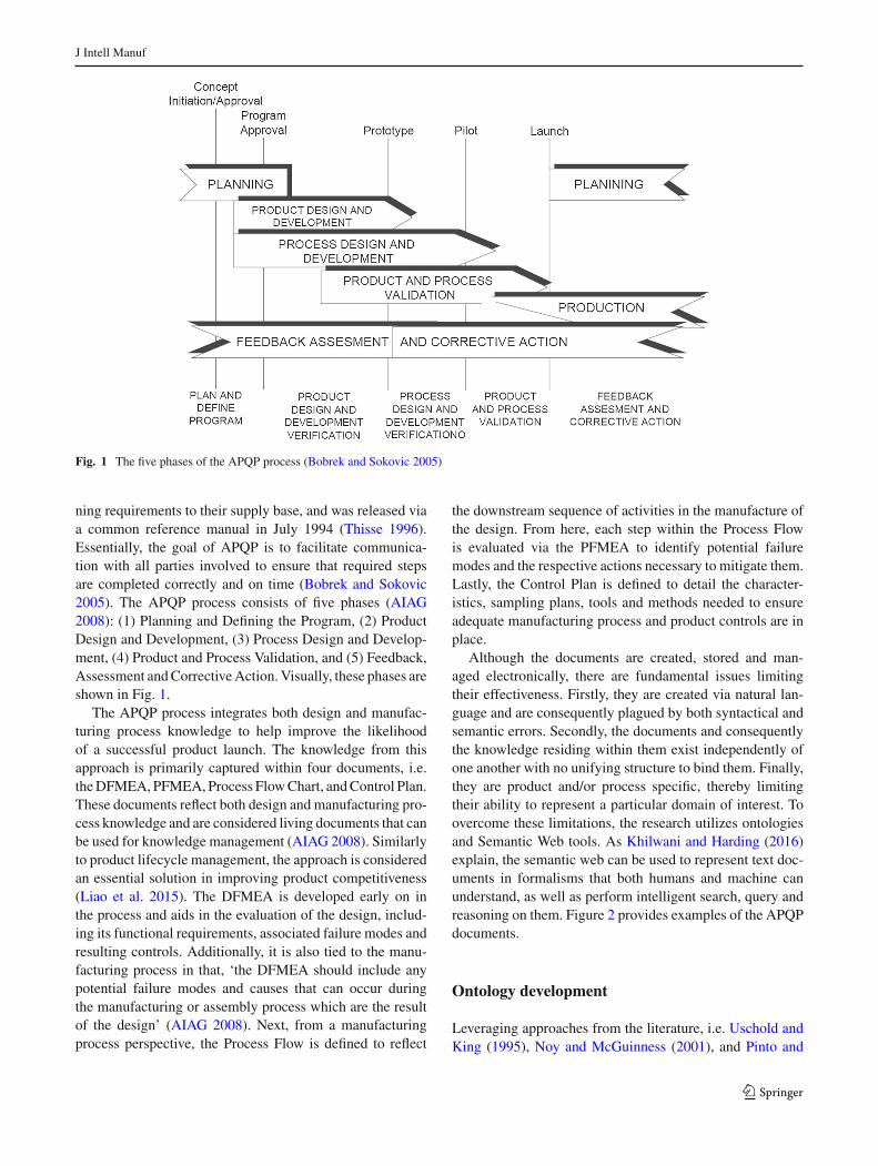
The APQP process integrates both design and manufac-turing process knowledge to help improve the likelihoodof a successful product launch. The knowledge from thisapproach is primarily captured within four documents, i.e.theDFMEA, PFMEA, Process FlowChart, andControl Plan.These documents reflect both design and manufacturing pro-cess knowledge and are considered living documents that canbe used for knowledge management (AIAG 2008). Similarlyto product lifecycle management, the approach is consideredan essential solution in improving product competitiveness(Liao et al. 2015). The DFMEA is developed early on inthe process and aids in the evaluation of the design, includ-ing its functional requirements, associated failure modes andresulting controls. Additionally, it is also tied to the manu-facturing process in that, ‘the DFMEA should include anypotential failure modes and causes that can occur duringthe manufacturing or assembly process which are the resultof the design’ (AIAG 2008). Next, from a manufacturingprocess perspective, the Process Flow is defined to reflect
the downstream sequence of activities in the manufacture ofthe design. From here, each step within the Process Flowis evaluated via the PFMEA to identify potential failuremodes and the respective actions necessary to mitigate them.Lastly, the Control Plan is defined to detail the character-istics, sampling plans, tools and methods needed to ensureadequate manufacturing process and product controls are inplace.
Although the documents are created, stored and man-aged electronically, there are fundamental issues limitingtheir effectiveness. Firstly, they are created via natural lan-guage and are consequently plagued by both syntactical andsemantic errors. Secondly, the documents and consequentlythe knowledge residing within them exist independently ofone another with no unifying structure to bind them. Finally,they are product and/or process specific, thereby limitingtheir ability to represent a particular domain of interest. Toovercome these limitations, the research utilizes ontologiesand Semantic Web tools. As Khilwani and Harding (2016)explain, the semantic web can be used to represent text doc-uments in formalisms that both humans and machine canunderstand, as well as perform intelligent search, query andreasoning on them. Figure 2 provides examples of the APQPdocuments.
Ontology development
Leveraging approaches from the literature, i.e. Uschold andKing (1995), Noy and McGuinness (2001), and Pinto and
123
J Intell Manuf
Control Plan
Actions Taken SE
VO
CC
DET
RPN
Part Twist 2 Root Sum Squared (RSS) tolerance analysis was conducted between mating components to assure failures are detected prior to design release.
2 #
Channel slot height too high
3 Root Sum Squared (RSS) Tolerance analysis conducted between mating components to assure failures are detected prior to design release. Tolerance checked with a manufacturing plant.
2 #
Current Design ControlsC
lass Potential Cause(s)
of Failure
Part Name & Number
Part Function
Potential Failure Mode
Action ResultsRecommended
Actions
Area / Individual Resp &
Comp Date
RPNPotential Effect(s) of
Failure DET
OC
C
SEV
- Retains crossbar to side rail
Crossbar not retained(OR-0014; OR-0037; OR-306; OR-0319; OR-0322, 0323, 0324)
Installation difficulty
Inability to install
Adjustment difficulty
Loss of cargo
Damage to vehicle/rack
Squeak and Rattle
Customer dissatisfaction
8
Revision Date:
Operation 10: Receive Steel Part# 9000095
P/N: 9000095 Mat'l type: Galv 40G/40G HDThickness: 0.26 +0.002/-0.0Width: 9.105 +/-0.005
No Furnction:Receive wrong steel.
JAC Manufacturing / Assembly:- Lost time waiting for new steel (1)- Difficult to meet customer releases (2)
Ford Assembly Plant:-N/A (Set up only)
End Customer:-N/A (Set up only)
2 Supplier ships incorrect steel
2 -Material part # and specification called out on P.O.-Supplier certification (Approved supplier list)- JAC SQAM requirements.
-Receiving work instructions-Packing slip-Material certifications- Visual inspection
5 20 None at this time
Responsibility& Target
Completion Date
Action Results
Actions Taken
Sev
Occ
Det
RPN
Recommended
Action(s)
Process Function Potential
FailureMode
PotentialEffect(s) of
FailureSev
Class
PotentialCause(s) /
Mechanism(s)of Failure
Occur
CurrentProcess
Controls -Prevention
CurrentProcess
Controls -Detection
Detec
RPN
OPERATION NUMBER:
Fabricate/
Assemble
Move Store Inspect SPECIALCHAR.
CLASS. CHARACTERISTICS
10Match to Shipper
Supplier:
Material Specification:
20 Per Material Handling Equipment.
30 Move steel to designated storage area.
40 Per Laser Mill Set Up Sheet
50 Per Work Instruction
60 Per Material Handling Equipment.
70
Steel Tag
Part Number 900095
Thickness: 0.026" +/-0.002"
Width: 8.550" +/- 0.005"
PROCESS DESCRIPTION
Receive Steel
Part# 900095
Move steel to storage area.
Store Steel
Roll & Spacer set-up of mill
Set up Pre-Notch Die & Locator in press.
Move steel to decoiler.
Verify steel
Date (Revised): Revised By:
Core Team:
Supplier Code:
Methods
Part / Process Name / Machine, Prod / Proc Evaluation
Proc. Operation Device, Tool, Specs / Measurement Sample Control Reaction
No. Description for Mfg. No. Product Process Tolerance Technique Size Freq. Method Plan
10 Receive Steel
Shipment from
Supplier and
receipt of
material.
Match to
packing slip
and no
damage
shipping.
Visual
determination
.
1Each
Shipment
Verify tags
against the
shipper
Tag,notify Quality, place in reject area,
contact vendor
20Move steel to
storage areaMaterial handling No damage Visual Each Skid
Material
Handling training
Tag,notify Quality, place in reject area,
contact vendor
JAC Part Number:Customer Part Number:
Date (Original):
Customer Engineering Approval / Date (If Req'd):
Key Contact / Phone:
Supplier / Plant:
Customer PCL:Part Name / Description:
l
Char.
Class.
Customer Quality Approval / Date (If Req'd):
Other Approval / Date (If Req'):Customer:
Supplier / Plant Approval / Date:
Fork Lift
Characteristics
Shipper
Prototype Pre-Launch ProductionPrototype Pre-Launch Production
Failure Mode & Effects Analysis (Process FMEA)
Potential Failure Mode & Effects Analysis (Design FMEA) Process Flow Diagram
Fig. 2 Examples of DFMEA, Process Flow Chart, PFMEA and Control Plan
Martins (2004), the necessary steps of ontology specification,conceptualization, formalization, operationalization, and uti-lization are captured in four operational activities to realizean effective ontology enabled knowledge reusemethodology.Systematically, the sequence follows a logical flow wherebythe ontology is conceptually defined, formalized via ontol-ogy editing tools, published to allow wide spread access, andthen utilized for application purposes. The final steps of themethodology are considered key for industry adoption in thatthe initial conception manifests into a functional tool for use.This final step is a surprising omission from many existingontology development efforts, but is crucial in being able torealize the ontology. Figure 3 below displays the steps thatcomprise the approach.
Ontology development: high level concept mapping
To develop the ontology, an iterative Waterfall feedbackapproach (Royce 1970) is employed. First, concepts areidentified within each of the APQP documents and thenrelationally mapped to pertinent others in each subsequentdocument. Similar to Sanya and Shehab (2015), the researchemploys a modular approach to help manage complexity byidentifying and connecting concepts within each document.As well, given the ontology includes concepts from the fail-
ure centric or FMEAdomain, it borrows terms and associatedproperties from related efforts, e.g. Molhanec et al. 2011;Zhao and Zhu 2012. Finally, using a second iterative pass,the concepts and their relationships are re-evaluated to ensureconsistency within the mappings.
To begin, since all manufacturing companies have anactual or intended customer base, the highest class in theontology is defined as class ‘Customer’. Reporting into thisclass is class ‘Program’, which is used to connect programssupplied to these customers. This connection is establishedvia the object property ‘hasProgram’. From here, the designitems that are supplied to the program are defined. The class‘Program’ is connected to class ‘DesignItem’ via the objectproperty ‘hasDesignItem’. Next, class ‘DesignItem’ is thentied to the classes of ‘DFMEA’, ‘ProcessFlow’, ‘PFMEA’,and ‘ControlPlan’. These four classes represent the primarysources of knowledge from the APQP process. Note, tominimize the amount of characters within the ontology, man-ufacturing process items have been shortened to simply,process items. Thus, for these four classes that emanate fromclass ‘DesignItem’, the ontology captures knowledge withinthe design realm, i.e. ‘DFMEA’, and as well as those withinthe manufacturing realm, i.e, ‘Process Flow’, ‘PFMEA’ and‘ControlPlan’. As shown in Fig. 4, these linkages establishthe high-level connection between a company’s customers,
123

J Intell Manuf
Processes
Step 1: Ontology Development
•Processes: Collec�ve concept and property iden�fica�on along w/rela�onal mapping
•Tool: Graphical edi�ng, e.g. Y editor
Step 2: Ontology Formaliza�on
•Processes: Formal ontology development, i.e., class crea�on, property crea�on, individual and property assignment, reasoning
•Tool: Ontology editor tool, e.g. Protégé
Step 3: Opera�onalize
•Processes: Publish ontology and/or store ontology for access
•Tools: e.g. Web hos�ng, triple store.
Step 4: U�liza�on & Extension
• : Query the ontology, extend the ontology, package the ontology for greater mainstream usage.
•Tools: e.g. SPARQL, SPARQL Endpoint, developer so�ware
Fig. 3 Methodology for ontology development and utilization
Fig. 4 Design and process manufacturing ontology development: high level concept map
their associated programs, and their corresponding designitems and design and manufacturing process knowledge. Itis instructive to note though, the ontology is not limited tothese four design and process knowledge classes. In fact, itcan be scaled to include additional classes associatedwith thedesign items supplied to the program, e.g., design validationtesting, manufacturing strategy plan, etc. Once all conceptsare identified, a graph-editor is employed to visually display
andvalidate the ontology [e.g., the freely available yEDgrapheditor (yWorks GmbH 2015)].
Ontology development: design concepts branch
The focus now shifts to the design branch and the associatedconnections within it. Here, the primary connection to class‘DFMEA’ begins with class ‘DesignFunction’. This connec-
123

J Intell Manuf
Fig. 5 Design and process manufacturing ontology development: design branch
tion establishes the linkage between the design item and itsfunctions and associated potential design failure modes.
The class ‘PotentialDesignFailureMode’ is connectedto corresponding classes, ‘PotentialCauseofDesignFailure-Mode’, and ‘PotentialEffectofDesignFailureMode’.The class‘PotentialEffectofDesignFailureMode’ is associated withdata properties ‘SeverityRating’ and ‘Classification’ to pro-vide insight into the significance of the failure mode. Thisunderstanding is crucial in determining the amount of miti-gation required to address the failure mode, i.e., a failure ofhigh severity is generally given more attention than one withlower severity. Within the ‘PotentialCauseofDesignFailure-Mode’ class, there are connections to both prevention anddetection controls, as well as their respective Risk PriorityNumber (RPN) and occurrence rating. These connections arevital for enhancing the knowledge base of the design groupas it provides information on known issues, associated sever-ity levels and the controls identified for mitigation. When
employed, this leads to greater quality and reliability of theproduct. As Cassanelli et al. (2006) indicate, a good FMEAimproves reliability by introducing proper corrective actionsthat lower failure rates. The design branch of the ontology isshown in Fig. 5.
Ontology development: process concepts branch
The next branch describes the relationships pertaining to theassociated manufacturing process knowledge of the designitem. Here, the connections stem from the class ‘Operation’,which defines the activities associated to the manufacturingprocess. This class is the central terminal upon which theconcepts from the Process Flow, PFMEA and Control Planare routed. This is a logical designation in that the individu-als within the class comprise the manufacturing process andhence are the hub for further analysis. From here, similarto the DFMEA, potential failure modes and their respec-
123
J Intell Manuf
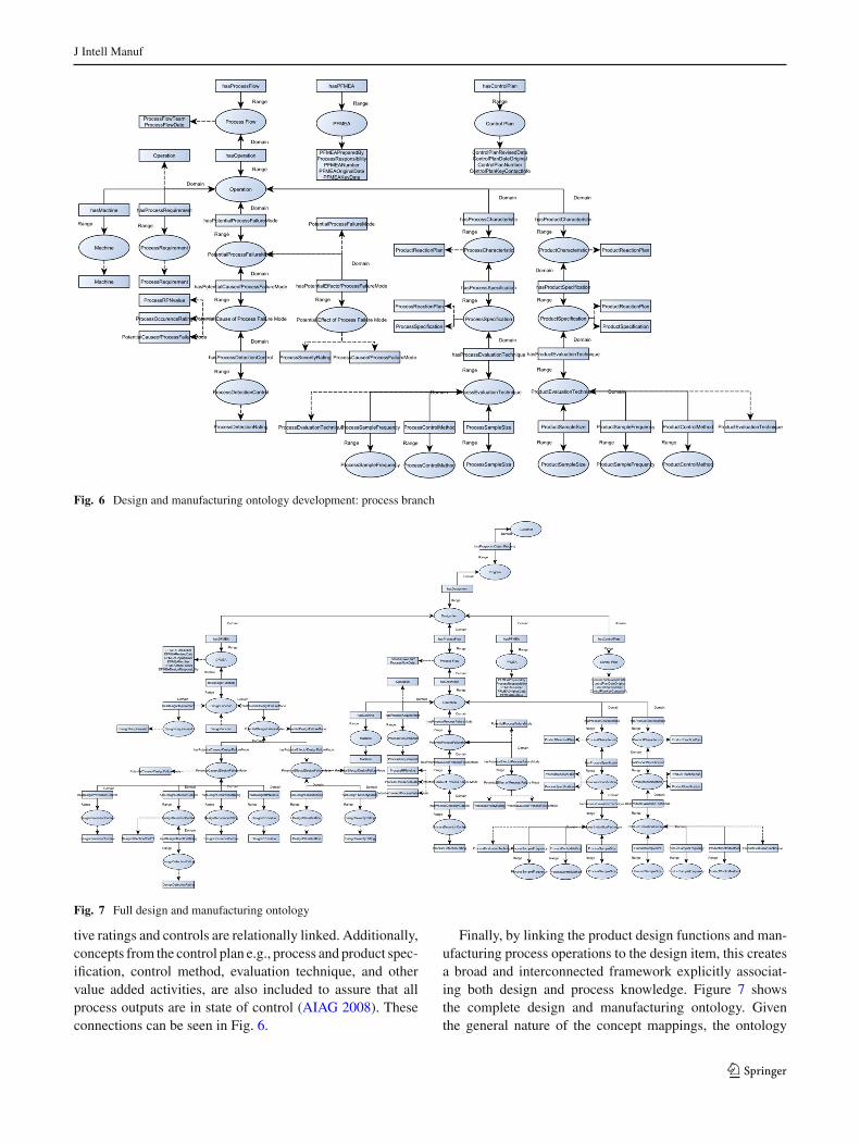
Fig. 6 Design and manufacturing ontology development: process branch
Fig. 7 Full design and manufacturing ontology
tive ratings and controls are relationally linked. Additionally,concepts from the control plan e.g., process and product spec-ification, control method, evaluation technique, and othervalue added activities, are also included to assure that allprocess outputs are in state of control (AIAG 2008). Theseconnections can be seen in Fig. 6.
Finally, by linking the product design functions and man-ufacturing process operations to the design item, this createsa broad and interconnected framework explicitly associat-ing both design and process knowledge. Figure 7 showsthe complete design and manufacturing ontology. Giventhe general nature of the concept mappings, the ontology
123

J Intell Manuf
can reasonably be applied to any design and manufacturingproduct.
Ontology formalization
To formalize the ontology, an ontology editor tool can beemployed. The research utilized Protege, a graphical toolfor ontology construction developed at Stanford Univer-sity (Stanford Center for Biomedical Research 2015). Thesequence of steps used is as follows: (1) Create classes, (2)Create properties, (3) Add individuals & assign properties,and 4) Run Reasoner and validate subsumption testing.
The ontology’s concepts were defined as classes. Notethat all classes are of subclass ‘Thing’, and are disjointedto prevent an individual from being an instance of morethan one class (Horridge 2004). Essentially, this is doneto avoid multiple inheritance and to support logical infer-ences. Next, the object properties connecting the individualsbetween classes were defined. To denote ownership betweenthe domain and range between classes, a convention of start-ing each object property with ‘has’ was employed, e.g., the
object property connecting class ‘DesignItem’ with class‘DFMEA’ was named, ‘hasDFMEA’. Next, the data prop-erties for the individuals were defined. Here, given the rangefor the data property is a value, and not a class, the ‘has’ con-vention for the object properties was not employed. Instead,simply the name of data property was used, e.g. the dataproperty for identifying the part number for class ‘Desig-nItem’ was named, ‘PartNumber’. Next, the individuals foreach class were defined. To assist with clear delineationbetween ‘DesignItem’ individuals, the type of design itemand a sequential entry number were used as prefixes. Forexample, to identify thefirst entry of a design itemcalled ‘EndSupport’, and its corresponding Control Plan, the followingconvention was employed: ‘EndSupport1ControlPlan’. Thistype of naming convention helps to clearly distinguish theintent and class association of the individual being defined.Next, each individual was assigned to their respective classtype, and object and data property (as applicable). Finally,once all the individuals were defined, Protege’s reasoner toolwas employed. The reasoner is used to test whether or notone class is a subclass of another, a process known as sub-
Fig. 8 Partial snapshot of published ontology
123
J Intell Manuf
sumption testing (Horridge 2004). Protege version 4.3.0 hastwo reasoner options, FaCT++, andHermiT 1.3.8. FaCT++ isa Description Logics (DLs) reasoner designed with tableauxalgorithms and optimization techniques (Tsarkov and Hor-rocks 2006), while HermiT is a more recent DL reasonerthat employs ‘hyper-tableau’ calculus to address problemsdue to nondeterminism and model size (Shearer et al. 2008).The ontology was run through both reasoners and no errorsemerged.
Publication of the ontology
Publishing the ontology is the process ofmaking the ontologyavailable on the web. The obvious benefit in doing so is thatonce complete the ontology can be accessed online. Addi-tionally, enhancing the ability to interconnect knowledge,SPARQL is able to query multiple online and networkedontologies. It is important to note that this type of wide acces-sibility facilitates greater knowledge sharing, and contributesto the virtual enterprise necessary to compete in today’sglobal marketplace (Tian et al. 2002).
Once the ontology was formalized via Protégé, it was thenuploaded onto the web via a simple freeware file servingclient. In Fig. 8, a screenshot of the uploaded ontology is
shown. Finally, it is noted that an alternate source of ontologystorage is available via the use of a triple store i.e. a databasedesigned specifically for retention and retrieval of triples viasemantic query. These stores allow for distribution and scala-bility over the conventional single machine RDF data storage(Khadilkar et al. 2012). For the purpose of this case study, asimple upload was employed to demonstrate the viability ofthe approach.
Industrial application: case study
To demonstrate the functionality and utility of the ontol-ogy, it was employed using data and a typical contextfrom the automotive industry. The data is derived from theauthor’s industrial experience within an automotive supplierof exterior trim. In terms of the context, as a supplier andmanufacturer of goods, it is imperative to reuse knowledgefrom past and like products and processes to ensure success-ful product launches and to minimize production disruptionsor product failures. Thus, a key activity when planning newproducts and processes is to revisit material from like pro-grams in order to capture and reuse past knowledge. Forexample, an engineer planning the design of a new product
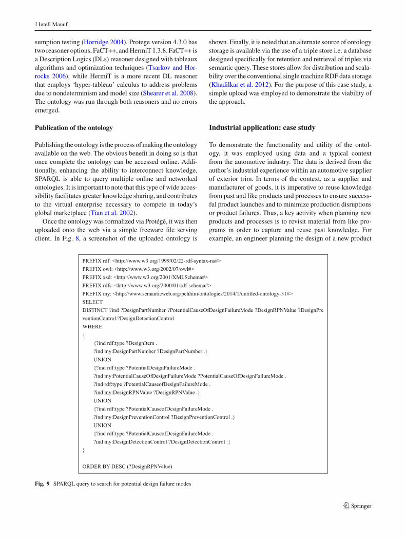
PREFIX rdf: <http://www.w3.org/1999/02/22-rdf-syntax-ns#> PREFIX owl: <http://www.w3.org/2002/07/owl#> PREFIX xsd: <http://www.w3.org/2001/XMLSchema#> PREFIX rdfs: <http://www.w3.org/2000/01/rdf-schema#> PREFIX my: <http://www.semanticweb.org/pchhim/ontologies/2014/1/untitled-ontology-31#> SELECT DISTINCT ?ind ?DesignPartNumber ?PotentialCauseOfDesignFailureMode ?DesignRPNValue ?DesignPreventionControl ?DesignDetectionControl WHERE { {?ind rdf:type ?DesignItem . ?ind my:DesignPartNumber ?DesignPartNumber .} UNION {?ind rdf:type ?PotentialDesignFailureMode . ?ind my:PotentialCauseOfDesignFailureMode ?PotentialCauseOfDesignFailureMode . ?ind rdf:type ?PotentialCauseofDesignFailureMode . ?ind my:DesignRPNValue ?DesignRPNValue .} UNION {?ind rdf:type ?PotentialCauseofDesignFailureMode . ?ind my:DesignPreventionControl ?DesignPreventionControl .} UNION {?ind rdf:type ?PotentialCauseofDesignFailureMode . ?ind my:DesignDetectionControl ?DesignDetectionControl .} }
ORDER BY DESC (?DesignRPNValue)
Fig. 9 SPARQL query to search for potential design failure modes
123

J Intell Manuf
Fig. 10 SPARQL output result
would be interested in knowing what types of design failuremodes exist for a particular product and what types of con-trols are in place to mitigate these failures. Additionally, theywould also want to know what types, and magnitudes of riskare associatedwith them. Fortunately, this knowledge is oftencaptured within the APQP documents previously described.Unfortunately, given the aforementioned limitations associ-ated to these documents, e.g., standalone, loosely kept, etc.,it is often difficult to locate the documents and glean the rel-evant knowledge within them. As a result, the knowledgecaptured goes unutilized. To address this, we offer the uti-lization of our ontology.
Revisiting our industrial case, we loaded instances of aDFMEA from our automotive supply source into our onto-logical framework and applied a complex query to providethe results of a typical search as described above. In detail,we asked that for a particular design item, what potentialfailure modes exists and what types of prevention and detec-tion controls have been identified to mitigate their failure?Additionally, we also applied an operation to rank order thepotential failure modes by Risk Prevention Number (RPN)in order to identify those risks of highest significance. Toobtain these results, we generated the SPARQL query shownin Fig. 9 below.
After the query was ran, the resulting output was cap-tured in Fig. 10. SPARQL is able to accurately identify thespecific subset of requested information, rank order the vari-able of interest and provide corresponding results. This queryability is a significant enhancement over traditional keywordbased searches in that it does not muddy the search resultsby simply providing a text field match; instead, it is target-ing a specific area of the data to provide a more preciousand richer response. In a single query, the ontology and theuse of Semantic Web tools, is able to unravel a complex setof data and provide rich and accurate results. This abilityhelps overcome a major existing weakness with the reuse ofknowledgewithin this industry, i.e. instead of having to scrollthroughmultiple documents/files and apply various keywordsearches to find specific information of interest, our ontolog-ical approach allows a user to more rapidly and preciselylocate this information, thereby increasing the likelihood ofreusing it.
Results and discussion
As competition in themanufacturing sector increases, knowl-edge management maintains an important role. As Jardim-
123
J Intell Manuf
Goncalves et al. (2016) indicate, there is a prominent needfor information systems to have an agile capability of han-dling and maintaining knowledge. Turning to ontologiesand the Semantic Web offers these capabilities and is acompelling option for an organization to gain greater compet-itive advantage. By encoding design and process knowledgeinto ontologies, organizations are able to capture, share andaccurately query these knowledge bases for reuse with fewgeographical limitations. The research presents a thoroughand significantly enhanced ontology from existing offeringswithin the literature. This broader effort connects productdesign andmanufacturing process knowledge to significantlyenhance existing ontological efforts from the manufacturingfailure mode domain. The functionality and utility of theontology is demonstrated through the development and uti-lization of our ontology to solve a real world issue. Via ourapproach, we were able to effectively combine relevant andactionable knowledge from both the design and manufactur-ing process domain, and apply a query to retrieve rich andrelevant information. Moreover, because our ontology con-tains rich, yet generalized interconnected product design andmanufacturing process based concepts, it can realistically beemployed across the manufacturing industry. Additionally,to address the lack of wide spread usage of ontologies, weoffer an effective and systematic methodology for ontologydevelopment and usage.
In terms of future research efforts, the challenge ofmainstreaming ontologies and the use of SemanticWeb tech-nologies is still quite formidable.While a clear framework ofontology development and utilization is offered, the frontendportion of the process can still be improved from an automa-tion standpoint. For example, although users knowledgeableof SPARQL can develop and utilize queries to draw accurateand rich information, this level of knowledge is esoteric andhence not useful for mass consumption. Consequently, addi-tional efforts can focus on developing user-friendly interfacesthat mask the SPARQL programming requirement, therebyallowing users access to improved queries without having toprogram the language. Finally, while our ontology is a soundinitial offering, we recognize that it can be further extendedto include other relevant forms of both design and manufac-turing process knowledge.
Acknowledgements We thank the two anonymous reviewers for theirexcellent inputs and suggestions that allowed us to significantly enhancethe quality of the manuscript.
References
AIAG. (2008). Advanced product quality planning and control plan(APQP). Southfield: Automotive Automotive Industry ActionGroup.
Ameri, F., & Patil, L. (2012). Digital manufacturingmarket: A semanticweb-based framework for agile supply chain deployment. Journalof Intelligent Manufacturing, 23(5), 1817–1832.
Bobrek,M.,&Sokovic,M. (2005). ImplementationofAPQP—Conceptin design of QMS. In 13th International scientific conference onachievements in mechanical and materials engineering. Gliwice-Wista, Poland.
Borst,W. (1997).Construction of engineering ontologies. Ph.D. Thesis,University of Tweenty, Enschede, NL.
Brachman, R., & Levesque, H. (1986). Knowledge representation andreasoning. Annual review of computer science., 1(1), 255–287.
Cassanelli, G.,Mura,G., Fantini, F., Vanzi,M.,&Plano, B. (2006). Fail-ure analysis-assisted FMEA. Microelectronics Reliability, 46(9),1795–1799.
Chandrasegaran, S., Ramani, K., Sriram, D., Horvath, I., Bernard, A.,Harik, F., et al. (2013). The evolution, challenges, and future ofknowledge representation in product design systems. Computer-Aided Design, 45(2), 204–228.
Chandrasekaran, B., Josephson, J., & Benjamins, V. (1999). What areontologies andwhy dowe need them? Intelligent Systems and theirApplications IEEE, 14(1), 20–26.
Chungoora, N., Young, R., Gunendran, G., Palmer, C., Usman, Z.,Anjum, A., et al. (2013). A model-driven ontology for manufac-turing system interoperability and knowledge sharing. Computersin Industry, 64(4), 392–401.
Desouza, K., & Evaristo, R. (2003). Global knowledge managementstrategies. European Management Journal, 21(1), 62–67.
Dittmann, L., Rademacher, T., & Zelewski, S. (2004). PerformingFMEA using ontologies. In 18th International workshop on qual-itative reasoning (pp. 209-216). Evanston, USA.
Ducharme, B. (2013). Learning SPARQL (2nd ed.). Sebastopol:O’Reilly Media Inc.
Ebrahimimpour, V., Rezaie, K., & Shokravi, S. (2010). An ontologyapproach to support FMEA studies. Expert Systems with Applica-tions., 37(1), 671–677.
Ettlie, J. E., & Kubarek, M. (2008). Design reuse in manufacturingand services. Journal of Product Innovation Management, 25(5),457–472.
Fabian, B., Kunz, S., Konnegen, M., Muller, S., & Gunther, O. (2012).Access control for semantic data federations in industrial product-lifecyle management. Computers in Industry, 63(9), 930–940.
Hill, K.,Menk, D., &Cooper, A. (2016). Contribution of the automotiveindustry to the economies of all fifty state and the United States—See more at: http://www.cargroup.org/?module=Publications&event=View&pubID=16#sthash.gsYjhu4I.dpuf. Retrieved fromCenter for Automotive Research: http://www.cargroup.org/?module=Publications&event=View&pubID=16.
Hoffman, C., & Joan-Arinyo, R. (1998). CAD and the product mastermodel. Computer-Aided Design, 30(11), 905–918.
Horridge, M. (2004). A practical guide to building OWL ontologiesusing the protege-OWL plugin and CO-ODE tools (1.3rd ed.).Manchester: The University Of Manchester.
Iarovy, S., Ramis, B., Xiangbin, X., Sampath, A., Lobov, A., & Lastra,J. (2015). Representation of manufacturing equipment and ser-vices for OKD-MES: From service descriptions to ontology. In In2015 IEEE 13th international conference on industrial informatics(INDIN) (pp. 1069–1074). IEEE.
Imran,M., &Young, B. (2015). The application of common logic basedformal ontologies to assembly knowledge sharing. Journal of Intel-ligent Manufacturing, 26, 139–158.
Iyer, N., Subramaniam, J., Kuiyan, L., Yagnanarayanan, K., & Karthik,R. (2005). Shape-based searching for product lifecycle applica-tions. Computer-Aided Design, 37(13), 1435–1446.
Jardim-Goncalves, R., Grilo, A., & Popplewell, K. (2016). Novel strate-gies for global manufacturing systems interoperability. Journal ofIntelligent Manufacturing, 27(1), 1–9.
123
J Intell Manuf
Khadilkar, V., Kantarcioglu, M., Thuraisingham, B., & Castagna, P.(2012). Jena-HBase: A distributed, scalable and efficient RDFtriple store. In Proceedings of the 11th international semantic webconference posters & demonstrations track 12 (pp. 85–88). ISWC-PD.
Khilwani, N., & Harding, J. (2016). Managing corporate memory onthe semantic web. Journal of Intelligent Manufacturing, 27(1),101–118.
Laaroussi, A., Fies, B., Vankeisbelckt, R., & Hans, J. (2007). Ontology-aided FMEA for construction products. In 24th W78 ConferenceMaribor 26 (pp. 189–194).
Lee, B. (2001). Using FMEAmodels and ontologies to build diagnosticmodels. AI EDAM, 15(04), 281–293.
Liao, Y., Lezoche, M., Panetto, H., Boudjlida, N., & Loures, E. (2015).Semantic annotation for knowledge explicitation in a productlifecycle management context: A survey. Computers in Industry,71(1), 24–34.
Lin, H., & Harding, J. (2007). A manufacturing system engineeringontology model on the semantic web for inter-enterprise collabo-ration. Computers in Industry, 58(5), 428–437.
Lin,H., Harding, J., &Shahbaz,M. (2004).Manufacturing system engi-neering ontology for semantic interoperability across extendedproject teams. International Journal of Production Research,42(24), 5099–5118.
Lin, L., Zhang, W., Lou, Y., Chu, C., & Cai, M. (2011). Develop-ing manufacturing ontologies for knowledge reuse in distributedmanufacturing environment. International Journal of ProductionResearch, 49(2), 343–359.
Molhanec, M., Mach, P., Asamoah, D., & Mensah, B. (2011). Theontology based FMEAof lead free soldering process. In 34th Inter-national spring seminar (pp. 267–273). IEEE.
Negri, E., Fumagalli, L., Garetti, M., & Tanca, L. (2016). Requirementsand languages for the semantic representation of manufacturingsystems. Computers in Industry, 81, 55–66.
Noy,N.,&McGuinness, D. (2001).Ontology development 101: A guideto creating your first ontology. Stanford Medical Informatics.
Pinto, H., & Martins, J. (2004). Ontologies: How can they be built?Knowledge and Information Systems, 6(4), 441–464.
Royce, W. (1970). Managing the development of large software sys-tems. In Proceedings, IEEE Wescon (pp. 1–9).
Sanya, O. I., & Shehab, M. E. (2015). A framework for developingengineering design ontologieswithin the aerospace industry. Inter-national Journal of Production Research, 53(8), 2383–2409.
Shearer, R., Motik, B., & Horrocks, I. (2008). HermiT: A highly-efficient OWL reasoner. OWLED, Vol. 432.
Stanford Center for Biomedical Research. (2015). Protege. Retrievedfrom http://protege.stanford.edu/.
Swartout, B., Patil, R., Knight, K., & Russ, T. (1996). Toward dis-tributed use of large scale ontologies. In Proceedings of 10thknowledge acquisition for knowledge—based systems workshop.Banff, Canada.
Thisse, L. (1996). Advanced quality planning: A guide for any organi-zation. Quality Progress, 31(2), 73–77.
Tian, G., Yin, G., & Taylor, D. (2002). Internet-based manufacturing:A review and a new infrastructure for distributed intelligent man-ufacturing. Journal of Intelligent Manufacturing, 13(5), 323–338.
Tsarkov, D., & Horrocks, I. (2006). FaCT++ description logic rea-sonser: System description. Berlin: Springer.
Tsia, C. a. (2014). The State of Knowledge Management: 2014. SanDiego, CA: TSIA.
Uschold, M., & King, M. (1995). Towards a methodology for buildingontologies. In Workshop on basic ontological issues in knowledgesharing D (IJCAI’95), (pp. 6.1–6.10). Montreal, Canada.
Young, B., Gunendran, A., Cutting-Decelle, A., & Gruninger, M.(2007). Manufacturing knowledge sharing PLM: A progressiontowards the use of heavy weight ontologies. Internatinoal Journalof Production Research, 45(7), 1505–1519.
yWorks GmbH. (2015). Retrieved from www.yworks.com/en/products_yed_about.html.
Zhao, X., & Zhu, Y. (2012). Application research of ontology–enabledprocess FMEA knowledge management method. InternationalJournal of Intelligent Systems and Applications, 4(3), 34–40.
123