product classification and technical data 10 product...product classification and technical data ......
TRANSCRIPT

Section III Covered and Insulated Aluminum Wire and Cable
Chapter 10
Product Classification and Technical Data
This chapter deals with cable types available for power distribution including related user applications Insulated conductors for instrumentation communications and protection are not described Considerable information regarding applications engineering design and insulation is in previous chapters Installation practices and conshynector selection are covered in Chapter II For ease of reference some Chapter 7 descriptions of cable types are repeated in part
Manufacturers catalogs should be consulted for deshytailed specifications and particularly as to sizes available in each category To save space not all available sizes are included in the description of each classification Omissions however do not imply lack of use or demand Similarly only a few of the available insulations are listed as a part of the description of each type of cable Other varieties of insulation including those mentioned in Chapter 8 may be available upon inquiry
The product classifications in this chapter follow the plan of previous chapters by proceeding from the lowshyvoltage cables to those of high-voltage First to be considered are the service cables
The usual table of ampacity ratings is omitted in the descriptions of each style of conductor Instead reference is made to a specified vertical column of Tables 10 1 10-7 and 10-9 in which typical ampacity ratings are listed for the applicable conductor size insulation and temperature
Ampacity listings for installations to 35 kV are found in NEC Article 310 Tables 310-16 to 310-31 and except for utility installations the NEC is the governing docushyment See Appendix 9A of this Handbook for discussion of ampacity ratings as listed by lCEA
In addition a modified type of stranding 19 wire combination Unilay is now available as described in ASTM B 786 in its uninsulated form Details of the various sizes of this conductor are listed in Table 4-26
Service and Secondary Cables
Class 10-1 Messenger-Supported Service-Drop and Secondary Cable (Duplex Triplex and Quadruplexj (Figure 10middot1)
This cable ordinarily is installed by the power supplier
(utility) for both secondary runs and service drops The cable construction consists of a bare neutral-messenger support member which serves as a neutral cabled with one two or three insulated conductors Service-drop and secondary cable are commonly manufactured to comply with the appropriate ICEA Specification S-66-524 for crosslinked polyethylene (XLPE) insulated conductors rated at 900 C maximum and S-61402 for polyethylene (PE) insulated conductors rated at 750 C maximum Cables of this type are suitable for applications where phase-toshyphase voltage does not exceed 600 volts
The following are typical sizes and insulation thicknesse1 for phase conductors
Conductor size Thickness AWG orkcmil mils millimeters
8 through 2 45 114 1 through 40 60 152 250 through 500 80 203
Available sizes - Generally all constructions are availshyable in sizes No 6 through 410 with large sizes through 500 kcmil available upon special inquiry
Neutral-Messengers-Constructions are available with full Or reduced sizes AAC ACSR ACSRlAW and Alushyminum Alloy (6201) neutral-messengers
Based on the referenced guide below Table 10-1 ampacities at a fixed condition of 40C ambient no wind or sun are tabulated in Table 10-1
Insulated Phase ----
Conductor
Ba Neutral
Messenger
Fig 10-1 Neutral-supported duplex secondary cable with solid Or stranded po wer conductor and bare stranded neutral
10 1
covered and insulated aluminum wire and cable
Type insulation Table 10middot1 and construction Col R efe renee
Polyethylene Duplex Triplex 3 Quadruplex 4
Crosslinked Polyethylene
Duplex Triplex 1 Quadruplex 2
Class 10middot2 Preassembled Parallel Secondary Cable (Fig 10middot2)
This cable serves a similar purpose as Class 10middot1 exmiddot cept it is used more for secondary runs than for service drops The introductory comments for Class 10middot1 also apply to it The two or three insulated power conductors are laid parallel and are secured to a bare neutral messenger by means of flat aluminummiddotalloy binder ribbon applied helically about the assembly The usually available insulations are crossmiddot linked polyethylene (XLPE) rated 90C high density polyethylene (HDPE) and conventional polyethylene (PE) rated 75C of the same thicknesses as listed for Class IOmiddot The neutral messenger used with cables of Class 10middot2 is the same as those specified for Class 10middot1 cables either full size or reduced size Ampacities are the same as those for duplexmiddot triplex Class 10middot1 according to the kind of insulation
Class 10middot3 Reverse Twist Secondary Cable (RTS) (Fig 10middot3)
This cable is similar to Class 10middot1 and the introductory comments also apply RTS cable is generally used as secondary distribution cable and occasionally used for service drops Cable construction consists of two or three insulated phase conductors cabled about a straight neutralmiddot messenger with direction of lay reversed at regular specified intervals throughout the length of the cable The conductors are bound to the messenger with an aluminum flat strap binder This cable is particularly useful in secondary distributions and where Tmiddottaps are required since slack can be obtained by untwisting the cable conductors Ampacities for these constructions are listed in Table IOmiddot
Flat Bare Binder Neutral Wire Messenger
Fig 10-2 Preassembled parallel secondary cable
Insulated Flat Phase
Binder
Bare Neutral
Messenger
Fil 10middot3 Preassembled reverse lay twist cable
Class 10middot4 Type SE-Style U Service Entrance Cable (Fig 10-4)
Cable construction includes two or three insulated conductors with a bare concentric neutral considered as a conductor Three-conductor SE-Style U (SEU) cable is the more widely used construction It is employed as service entrance from the attachment point of the service drop cable down through the meter socket and then to the service panel Three-conductor cables consist of two insulated conductors paralleled about which is applied a bare concentric conductor The assembly is compacted protected and strengthened by a reinforcement tape and an extruded polyvinyl chloride (PVC) jacket applied overall SEU cable is manufactured to comply with the UL standard for service entrance cables (UL 854) Application is governed by local building codes which generally reference the NEe Phase conductors in service entrance cable are usually NEC types XHHW and RHW SE cables are recognized in Article 338 of the NEC for use as feeder and branch circuit conductors with certain limitations Typical applications include range and dryer circuits
Class 10-5 Type SE-Style SER Service Entrance Cable (Fig 10-5)
SER cables meet all of the requirements of Class 10-4 above for SEU cables Style SER cables differ from SEU in that the neutral conductor is insulated and cabled with the phase conductors This difference produces a round configuration for three-and four-conductor cables Availshyable constructions are three-conductor cable (two inshysulated phase conductors cabled with an insulated neutral conductor) and four-conductor cable (the same as threeshyconductor plus a cabled bare equipment-grounding conductor)
SER cables are suitable for voltages not exceeding
10-2
TABLE 10-1 Typical Ampacities for Various Sizes and Types of Stranded Conductors
in Cables of the Class Descriptions Mentioned in the Text
(600 Volts or Less)
NOiE It is suggeued that this table not be used diractly but only to supply information as a supplement to the Clan Descriptions which should be consulted first
Except for Classes 10-4 -5 and -8 the listed ampacitie$ afe based on 400C ambient for cable in air or 1n conduits in air and 200 C ambient for cables in buried duct or direct earth burial assuming 100 load factor and RHO-gO earth thermal resistivity The listed ampacitiei for Clauss 104 -6 and -8 are based an 300e ambient
Insulatfll Conductors
AWG kemU
12 10 8 6 4 2 1
IO 20 30 40 250 350 500 750
1000 1250 1500 1750 2000
1(1 10-2 10-3andl ~04l 10-6 105
Tmp I 90-1-4-75 - I 75 190 75 C
i( ~ x te~tlHpa lit Q lI bullbull l2 in60deg
CoLNo I (11
70 95
130
185 215 250 295
(2)
90 125
175 200 235 275
6 Obull a (31 (4)
60 BO 75
110 105
150 140 175 165 205 195 240 230
~ ~ 15)
40 50 65
100 110 125 150 fl175 200
Air 16)
64 B5
116 150 174 201 232 269 312 347 431 544 707 853 982
1103 1216 1321
I (7)
55 73 97
128 149 172 199 230 26S 297 370 466 606 730 840 944
1039 1128
Class 1()6 III middot1--middot Cla$$10middot7 _ 110-8 1- Class 10-9
u 15
Triplexod in Air
(8)
61 69 91
123 144 161 193 22 262 292 364 45B 59B 716
~
(9)
44 59 78
106 123 143 165 192 224 251 312 392 512 612
90 15 90 75 I 90 75 I 90 15160190 75 I 90 75 I 90 15
Triplex Tiplx I 3le ~ zlC or 31C
in Buried 3e in in Concentric in Conduit Duct Air Conduit NM Neutral 110) 1111 112)1131 I 114)iI15) (1111~(1 (ml_ ~
15 25
43 37 50 45 30 58 50 66 60 65 53 68 50 76 65 86 78 S5 70 76 65 150 135
102 87 II 103 115 92 102 87 190 175 122 104 131 119 135 108 122 104 220 200 139 119 150 136 155 125 139 119 250 225 159 137 172 156 lBO 144 159 137 280 255 189 162 196 178 205 166 189 162 315 290 217 186 226 205 240 192 217 186 365 330 249 213 250 227 265 214 249 213 400 360 303 259 304 276 330 265 303 259 480 435 381 326 372 338 410 330 3Bl 326 580 530 488 417 4B8 425 530 424 4SB 417 578 493 546 494 625 500 578 493
-L~ _--_
In Pli Duct
RibbOn not triplex ~1I1= ~IH
130 175 16 200 190
215225 245250
285 275 325 315 350 345 415 3BO
110 90 125 110 145 125
145170 195 165 225 190 250 215
ICI10-1(
90 151 75
Tripl$x 100 IF
(IC and ron Neutral) abfe
(25) 11261 (7)
105 96 50 135 123 6517 160 90 201 182 100 229 206 115 260 235 135 296 266 150
1338 170 370
303 331
448 39S 543 481 617 550
la-The listed ampacities generally are from ICEA tables and may differ from ratings in NEe 310 tables as qualified by footnotes and after adjustment for difference of ambient temperashy gt
tures If dif1erenres occur use adjusted NEC values when NEe conditions must be met
Some ratings are in even figures and others are roundad to nearest 6middotampere values This lack of uniformity Is expalnod by noting that ampacity ratings of sueceasive batches may show a variationmiddotof plusmn2 hence the rounding to nearest I) amperes is allowable Some listings from industrY sources are based on 62 tACS elumlnum conductivity but most tabulated values are based on 61 conductivity The effact on ampacity is only 810 of 1 in favor of the 62 aluminum hence the difference is ignored in the tables
Adjustment of ampaeity values for cables closely adjacent in rigid cable supports troughs or where there is no maintained spacing should be rriade according to factors in Appendix 9A gt Ampacities are from the NEe for throe-wire slngte-phase residential services
- s-o ashy
t)w
i
covered and insulated aluminum wire and cable
Un insulated
Insulated ------Phae
Conductors
Fig 10-4 Type SE-style U three-conductor service-entrance cable
SaInsulated Grounding
Phae Conductor
Jacket----
Insulated -------- Neutral
Conductor
Fig 10-5 Typical type SE-styte SER cable
600 volts SER cable is primarily used in residential wiring to subfeed distribution panels in multi-unit dwellings The four-conductor cable provides an insulated neutral required by the NEC for feeders and branch circuits as well as an equipment-grounding conductor Cable is sized per NEC requirements Where cables are used as branch circuit conductors cable ratings are based on the type of conductor insulation within the cable - for example XHHW for 900C dry locations at the applicable ampacity caned for in NEC tables
Class 10-6 600-11)(J() Volt Power and Lighting Cable (not especially designed jor direct burial) (Fig 10-6)
Cables of the 600-volt and lOOO-volt class are similar except for a slight difference of insulation thickness NEC describes the 6OO-0It class completely for code applications and its Art 710 refers to requirements for over 600 volts Under NEC conditions the (I)(J()-volt cables mostly are applied for certain circuits related to
industrial processes motor loads large fluorescent lighting installations and sometimes where ungrounded neutrals are used Some manufacturers include the II)(J()-volt cables in a group specified for 6Ol-21)(J() volts
Cables of the 6OO-voh class sometimes are referred to as building wires because of the extensive use of single conductors for interior circuits The Aluminum Building Wire Installation Manual and Design Guide of The Aluminum Association lists sizes of the 600-volt class and NEC designations of insulation for various iempershyatures and environments hence they are not repeated in this handbook This classification includes insulated single or multiplexed cables for installation in air duct cable tray metallic or non-metallic conduit or suspended from messenger It does not include multi-conductor cables (an assembly of several conductors under one jacket or sheath) nor cables designed especially for underground direct burial though some cables of this class may be suitable for direct burial
Table 10-2 shows the usual range of sizes and kinds
10-4
c
of insulation generally used for the 600-volt class on the basis of 100 percent insulation level with grounded neutral The insulation thickness for 1000 volts is slightly mOre than for 600 volts If the thickness is shown as a double number the right-hand value applies to the jacket only
The EPM-EPDM insulation listed in Table 10-2 represents the formulation used for 1000 volts or less of the EPR ozone-resistant insulation listed in Table 8-2
A
B
Jacket Insufion
L ____---l-(-1_
Flat BareBinder
o
Phase Conductors
Fig 10-6 Typical 600-voll insulated power and light cables A-No outer covering required B--Comparativey thick jacket neoprene etc C--Comparatively thin jacket nylon etc D-Assembled aerial cable phase conductors either
cabled or layed up with reverse lay twist to facilitate side taps
product classification and technical data
Ampacity ratings for these conductors in air at 40C ambient (not buried or in underground duct) are listed in the following deSignated columns of Table 10 1
90C 7SC
Single conductor in air
Each conductor of a triplexed assembly in air
Each conductor of a triplexed assemhly in steel conduit in air
Col 6
Cel 8
Col 10
Co 7
Co 9
Col 11
Ampacity rating of each conductor of a triplexed as sembly in buried duct at 20degmiddotC ambient is listed in columns of Table 10-1 as below
9OC 7SC Each conductor in iripEexed assembly
in nonmetallic duct buried Cot 12 Col 13 of two phase conductors and neutral
Class 10-7 Three-Conductor Cable (600-1000 Volts) (Fig 10-7J
Although a triplexed cable has three cunductors it was included in Class 10-6 because essentially it is comprised of three closely spaced single conductor cables and is not designated as a multi conductor cable
A multi-conductor cable on the other hand as usually defined has two or more phase conductors usually cabled and the entire assembly is enclosed in a Close-fitting tubular jacket or sheath which may contain fillers to round out its circular shape It may also have an insulating jacket under the sheath
Sector stranded conductors are sometimes used in three-conductor cable as a means of reducing diameter The Type SER service-entrance 6OOvolt cable qualifies as a three-conductor cable but because of its special application it is listed as Class 10-5 The Types NM and NMC also are three-conductor cables but because of availability only in small sizes for branch circuits they are separately considered as Class 10-8 It is characteristic of three-conductor cables that the outer jacket must fit closely hence pre-assembled cables in a comparatively large duct are not included Many portable power cables are three conductor cables with flexible neoprene or plastic jackets
Armored aluminum multi-conductor power cables Fig 107 available as Type MC (metal clad) with NEC conductors No 12 AWG and larger have an outer protective covering of corrugated or interlocked design A modification in branch-circuit and feeder sizes Type AC (armor clad) has an internal bonding strip of aluminum in intimate contact with the armor for its entire length Another style of Type Me aluminum corrugated cable has the tube formed around the assembly of insulated conductors with the longitudinal seam closed
Ampacity ratings for this class are from leRA Pub P~46-462 (1962) as described in Chapter 9
10 5
l obull0shy
TABLE 10-2
Typical Insulation Thicknessesmiddot of Power and Lighting Secondary Cables (600 volts)
I _
Cro Linked Polyethylene
Thickness of Insulation in Mils (11000 in) ------------------ shy
Polyvinyl Chloride
1Conductor Size
AWG-kcmil Cia B
900C Dry 750C Wet
XHHW
900C Dry 750C Wet USE-RHWshy
RHH++
750C Wet
THW
Nylon Jacket
THHN++ gooC Dry
THWN 750C Wet
SBR Rubber
750 C Wet Neoprene
Jacket RHWmiddotUSE
Butyl OOOC Dry 750 C Wet Neoprene
Jacket RHH-RHWmiddotUSE++
Stranded Mils mm Mils mm Mils mm Mils mm Mils
12-10 30 076 45 114 45 114 bullbull bullbull 45-15middot
8-2 45 114 60 152 60 152 bullbull 60-30
1-40 55 140 80 203 80 2031 50middot7 127 18180-45
213-600 65 165 95 241 95 2411 60middot8 152middot20 19565
501-1000 80 203 110 2791110 279 70-9 178-23 110middot65
1001-2000 95 241 125 318 125 318
mm Mils -------+~
114middot38 45-15
152middot76 60-30
203middot114 80middot45
216middot165 95-65
279middot165 110middot65
mm
114middot38
152-76
203-114
2 16middot165
279middot165
Q
a ~
Qiii Q
~ EPMmiddotEPDM Ethylene
Propylene
3shysect
Rubber 900C Dry 750C Wet r
Syn-Rubber Q
Jacket a RHH-RHW-USE++
Mils mm 8 ashyiigt
30middot15 076middot38
55-45 140middot114
65middot65 165-165
80-65 203middot165
100 insulation may also be used with ungrounded neutrals provided the fault-clearing devices clear the fault in less than one minute and completely de-energize the faulted section If this condition cannot be met it may -be necessary to use insulation for 133 percent level (see manufacturer) Ilf thickness is shown as a double number rightmiddothand number indicates thickness of jacketl
For No 12 values are 15middot4 mils (38middot10 mml for No 10 value are 20-4 mils 51middot tOmml for No8 and No6 values are 30middot5 mils (76middot13 mml for No4 and No2 value are 40middot6 mils (102middot15 mm)
middotmiddotmiddotA 3Qmil jacket is required for aerial instal1ation
++NEC limits wetmiddotlocation rating to 750 C but ICEA and industry ratings allow 900 C wet or dry for cables having these insulation thicknesses
For sizes No8 and No7 values are 45-15 mils (114middot38 mml for size No 6middot2 value are 45-30 mil~ (114middot76 mml
Coding Tape
Insulation Conductor
Armor Tape(Interlocking) or Corrugated
Grounding Conductors
Fillers
Fig 10-7 Typical three-conductor impervious-corrugated or interlocked corrugated armored cable
by welding and Ihe corrugations roll-formed to provide flexibility
Still another MC type is aluminum sheathed cable formerly Type ALS This cable has a smooth tubular aluminum sheath surrounding three or more NEC conmiddot ductors of branch-circuit size with ampacity ratings from 2()amp to 90middotamp The insulation of individual conmiddot ductors used in this cable type may be any listed for Class 10middot6 cables These cables are particularly useful in control circuit wiring where provision for growth is not necessary Its use eliminates cost of conduit installashytion and wire pulling
In any of these MC types a fourth insulated conductor can be included for three-phase Y middotconnected applications
The equivalent of a separate bare or covered grounding conductor may be included as one or more conductors in the interstices of the cable arrangement The grounding conductors for Type MC cables are tabulated in Section 79 of ICEA Standard 5middot66middot524 and Section 710 of 5-19-81 The protective sheath or armor is not designed for use as a neutral conductor and for interlocked metal strip design is not recognized as a grounding conductor
The exterior surface of metal clad cables must be additionally protected by a suitable jacketing material when exposed to destructive corrosive conditions Colored PVC jackets are commonly used for this purpose
There are moderate NEC limitations as to where Type MC and similar cables may be installed Generally they are placed in trays or on other rigid suppons in power stations industrial plants and commercial installations though some types are suitable for embedded or undershyground use
product classification and technical data
For calculating voltage drop in 6OO-volt three-conductor armored cable the factors of Table 9-6 may be applied using those for aluminum conduit for cables with alushyminum armor and those for steel conduit for cables with steel armor The armor is thinner Ihan the wall of standard conduit but since it is closer to the conductors its inductive effect is about the same
The ampacity of the three-conductor unarmored or aluminum-armored cables in air at 75degC with 40degC ambishyent is per Col 15 of Table 10-1 and at 90degC per Col 14 For three single-conductor cables in steel conduit the ampacity is as shown in Col 17 for 75degC and Col 16 for 90degC The range of available sizes of cables with weldedshytube corrugated armor differs from that ofcable with intershylocked armor For further information consult manufacshyturers lists
Three-conductor non-metallic-iacketed cable
This cable is similar to Type MC armored or sheathed cable exrept that the protective covering is a round plastic jacket instead of a metallic sheath or armor This design is used where it is desired to maintain a fixed configurashytion of the conductors along with moderate protection against crushing and abrasion such as when pulling through a duct or after installation on supports parshyticularly in wet locations The insulation of the individual conductors may be any listed for Class 10-6 cables though the conductors usuallY do not require additional jackeling In wet locations the insulation should be selected for wet conditions The outer jacket is usually of neoprene or polyvinyl chloride If the cable is in air at 4QoC ambient the ampacity rating of Col 15 for 750C and Col 14 for 900C of Table 10-1 may be used If installed in underground duct at 200C ambient Col 13 for 750C and Col 12 for 900C may be used
These plastic-jacketed three-conductor cables may be installed in the same manner as single power cables (Class 10-6)
Class 10-8 Types NM and NMC Nonmetallic Sheathed Cable (Fig 10middot8)
This twomiddot three- or four-conductor cable is used exmiddot tensively for interior wiring of branch circuits through the 75-amp ratings It is listed by UL for sizes No 12 through No 2 for aluminum The insulated conductors in the usual sizes of No 12 and No 10 are arranged in parallel for twomiddotconductor cables three and fourshyconductor cables are cabled into a round configuration Assemblies are enclosed in a moisture and abrasion resistant extruded PVC jacket The three-insulatedshyconductor round style is suitable for 3-wire circuits with one insulated conductor serving as neutral
NM and NMC cable is satisfactory for use in circuits nO exceeding 600 volts and where conductor temperatures
10middot7
covered and insulated aluminum wire and cable
Type NM (2middotCdr with Ground Oval Section) (Can be obtatned without gfOuodlng conductor
Type NM (3 Conductor Round Section) (Also available with bare grounding conducfor)
Fig 10-8 Type NM branch-wiring cables
do not exceed 600C Cable construclions are available wilh or without a bare grounding conductor
Conductors of No to size or smaller are solid and annealed for flexibility because an advantage of this type of cable is that it readily may be bent into place The Type IM cable is approved for installation in both exposed and concealed work in normally dry locations but not for exposure to corrosive conditions nor may it be run in masonry concrete or plaster
Type NMC cable resembles type NM but has an
integral jacket which is fungus- and corrosion-resistant Installation in moist or corrosive locations is approved and under certain conditions it may be used where Type NM is prohibited Neither type is approved for serviceshyentrance use nor for locations as limited in NEC Section 336-3 Ampacities based on 300C ambient in Col 18 Table 10-1
are
Class 10-9 Secondary-Distribution Single- or Three-Conductor Cables for Underground Residential Distribution (URD) 600 Volts (Fig 10-9)
Although these cables are usually designated as for URD they are of course suitable for any other direct burial use within their ratings NEC cables designated Type UF (underground feeder) are included to 40 Certain other conductors in Class 10-6 are also suitable for direct burial such as USE or the combination Type USE-RHW -RHH available in several insulations Some sizes are available in both solid and concentricshystranded aluminum conductors the solid type is an intermediate temper
Bare aluminum neutrals are usually not permitted for URD cables because of the possibility of corrosion in wet earth A popular cable is a triplexed assembly of which one conductor is an insulated neutral Fig 1O-9C
A less frequently used form has a copper-wire neutral spiraled closely around one or two paralleled insulated conductors (Fig 1O-9A amp 9B) Copper is used for the earth contact because of its resistance to corrosion under buried conditions Still another form is the ribbon
3
(A) (8) Two-Conductor Three-Conductor
Concentric Neutral Type Concentric Neutral Type
Plain or Corugaled Platic Duct
(e) Triplex Type
(D) IE)Ribbon Trlplexed
Type Plasllc Conduit Typo
Note A concentric-neutral cable may be used instead of the triplexed as shown for installation in plastic conduit (El
Fig 10-9 Typical600-volt cables lor direct burial
10middot8
product classificatIon and technical data
TABLE 10-3 Typical Insulation Thicknesses of Secondary Cables (600V) for Direct Burial or
Underground in Duct Thickness of Insulation in Mils (11000 in_) Millimeters
(1 ) (2) Crossmiddot Linked
(3) Polyethylene
(4) (5) (6) Polyvinyl Chloride or Low-Density Polyethylene
Conductor Size
WG-kcmilA
Concentric Neutral or Triplexed
90degC Mils mm
Parallel Ribbon Type 90degC
Mils mm
Concentric Neutral or Triplexed
75degC Mils mm
Parallel Ribbon Type 75degC
Mils mm
Plastic Conduit Type 75degC
Mils mm
4-2 1-40 225-500
60 80 95
152 203 241
75 85 95
191 216 241
60 80 95
152 203 241
95 125 -
241 318 -
60 80 95
152 203 241
Sizes are concentric stranded -conductors for solid-conductor sizes (except for Column 5) refer to manufacturer Special inquiry also is required for availability of sizes for Column 2 for sizes above 300 kernil
The thicknesses shown include 30 mils for jacket
cable in which two parallel insulated phase conductors have an insulated neutral between them Fig 10-9D The insulation is extruded over the three conductors simultaneous1y so there is a thin connecting web between the conductors or the web may be only a part of a jacket The web is easily torn away during installatio~
Available constructions include cable in a duct This construction consists of two or more conductors preshyassembled at the factory in a plastic duct (Figure 10-9E) Use of this product provides for conductor replacement after installation Duct sizes are compatible with existing accessories and through supplier inquiry may be sized to allow for some degree of enlargement on the system as installed
The insulated conductors in any of the above-described cable assemblies can be any of the conductors of Class 10-6 listed by NEC as suitable for direct burial
Table 10-3 shows the usual range of sizes and kinds of insulation generally used for the 6oo-volt cables of the types described and Table 10-1 Cols 19 to 26 sumshymarizes ampacities that conform to ICEA requirements and to local codes requiring that underground secondary service cables leading directly to the home be UL-listed Care should be taken by the purchaser to assure that the product offered is UL-Iabeled for these applications where required
The threeCconductor URD cables for 600 volts in the arrangements shown in Fig 10-9 are for three-wire single-phase circuits If the cables are for three-phase (3 or 4 conductors) the ampacities shown in Table 10-1 should be reduced Consult suppliers
Cols 19 and 20 of Table 10-1 list ampacities of 600shyvolt buried cables of the concentric-neutral type (having spiraled bare copper neutrals) at 200 C ambient for inshysulation suitable for 900 C and 75 0 C respectively The
ampacities of triplexed buried cables are listed in Cols 25 and 26 The ribbon type has ampacities according to inshydustry sOurces and tests as listed in Col 21 for 900 C and for 750 C as in Col 22
In all cases of direct burial Or duct installation an earth thermal resistance of RHO-90 is assumed with a load factor of 100 percent that is the cables will withstand these ampacity ratings for continuous operation
The ampacity ratings of the cables pre-assembled in plastic ducts for the 900 C ratings are in Col 23 and for the 75 0 C ratings in Col 24
Class 10-10 Portable Aluminum Cables (600 Volts or less) (Fig 10-10)
Portable aluminum cables either single or multiple conductoc are constructed to yield a high degree of flexibility Flexible cables usually employ an intermediate tempered aluminum conductor which is insulated with a synthetic rubber or thermoplastic material These conductors are phase-identified for circuit applications Two or three conductor cables with or without equipment grounding conductors are middotcabled together with the necessary fillers to construct a round cable and employ an overall jacket of thermoplastic or synthetic rubber Flat constructions are also available with conductors arranged parallel to one another and with a common overall jacket Portable aluminum cables possess a lighter weight than other constructions which facilitates their use Single-conductor portable cables are available for special applications where flexibility is a requirement due to installation handling or vibration is a consideration
Single-conductor portable cables usually are available from No 8 to 1000 kcmi and multiple conductor portable cables from No 12 to 40 AWG Ampacity ratings are usually approximately as follows for 75 0 C
10middot9
covered and insulated aluminum wire and cable
A S C D
AI Two~conductor (S) Twomiddotsonductor (C) Two~conductor (D) Three~c(JOductor
With Flat With Stranded With Stranded Equipment- Equipment~ Equipmentmiddot Ground Ground Ground Conductor Conductor Conductor
Fig 10-10 Typical cross-sections oj portable cables comshy Note The web-tape cushion prevents longitudinal sepshyprising aluminum conductors insulation web-tape cushion aration of insulation and jacket during bending oj the and overall jacketing cable
operating temperatures and 400C ambient temperatures
Single-conductor cables Col 3 in Table 10middot1
Two-conductor parallel or round type Col 4 in Table 10middot1
Three-condllctor round Col 27 in Table 10middot1
Often a long portable cable is partly held on a gathershying reel The above ampacity values are reduced for such cases by multiplying by the foUowing correction factors
One layer on roll 085 Two layers on roll 065 Three layers on roll 045 Four layers on roll 035
Class JOmiddotll (Fig 10-11) Aluminum Control Cables (for 600 Volts or less)
Because of the wide variety of multimiddotconductor cables used for control and signal circuits and the generally small size of the individual conductors no detailed descriptive listing of them is attempted for this book The individual conductors (either stranded or solid) are insulated with compounds that best meet conditions and the whole assembly is contained within a round thick overall jacket of neoprene or thermoplastic material Where the application environment is severe constructions are available with reinforced overall jackets or armoring
These control cables have wide application in utilities industrial municipal and railroad installations for control andmiddot signal purposes The automatic control of machinemiddot tool operations is a recent application for which control cables of oil-resistant type are used Manufacturers lists should be consulted
10middot10
Fig W-ll Typical aluminum multimiddotconductor control and signal cable available with 2 to 18 conductors A WG 9 to 14 suitable jor installation in ducts direct burial or jor aerial suspension jrom messenger
Cables For Primary Distribution Voltages The types and voltage range of primary distribution
cables with aluminum conductors were briefly described in Chapter 7 Those with rubber or thermoplastic insulamiddot tions mostly are for 5middot 15- 25- and 35middotkV all with grounded neutral The 3-kV and 8-kV ratings sometimes are listed but are less used because the trend is toward the next higher voltage in anticipation of load growth even though the actual increase from the lower circuit levels may be long delayed
Customarily primary-distribution insulated cables are voltage-rated on the basis on the phase-to-phase voltage of a three-phase circuit of which they are a part or would be a part if the three-phase circuit were complete Thus an insulated conductor of a single-phase branch circuit including a phase wire and a ground wire that is conshynected to the wye ground of a 25-kV three-phase wyeshygrounded circuit is still rated 25 kV although the actual rms kV of the single-phase circuit is only 25113 or 144 kV This notation applies principally to the single insushylated primary conductor of the two-conductor cable that supplies the single-phase transformer that feeds the secshyondary three-wire circuits
Cable descriptions in this book and in the literature disshytinguish between the insulation thicknesses required for high-voltage cables in circuits with grounded neutral and those with ungrounded neutral the latter requiring thicker insulation It is recognized however that there are other conditions than lack of neutral ground that may make a thicker insulation desirable To meet this condition the concept of grounded and ungrounded neutral is in the process of being eliminated as a sole criterion Instead the insulation thicknesses are assigned based on insulation level (AEIC 5 and 1987 NEC Table 310-13)
The selection of the cable insulation level to be used in a particular installation shall be made on the basis of the applicable phase-to-phase voltage and the general system category as outlined below
100 Percent Level-Cables in this category may be apshyplied where the system is provided with relay protecshytion such that ground faults will be cleared as rapidly as possible but in any case within one minute While these cables are applicable to the great majority of cable installations which are on grounded systems they may be used also on other systems for which the applicashytion of cables is acceptable provided middotthe above clearing requirements are met in completely de-energizing the faulted section
133 Percent Level-This insulation level corresponds to that formerly designated for ungrounded systems Cables it this category may be applied in situations where the clearing time requirements of the 100 percent levei category cannot be met and yet there is adequate assurance that the faulted section will be de-energized in a time not exceeding one hour Also they may be used when additional insulation strength over the 100 percent level category is desirable
173 Percent Level--Cables in this category should be applied on systems where the time required to deshyenergize a grounded section is indefinite Their use is recommended also for resonant grotindedsystems Conshysult the manufacturer far insulation thicknesses
bull Where additional insulation thickness is desired it shall be the same as for the 133 percent insulation level
product classification and technical data
The AElC reference to the preceding statement reshygarding insulation levels also includes the following
In common with other electrical equipment the use of cables is not recommended on systems where the ratio of zero to positive sequence reactance of the system at the point of cable application lies between -I and -40 since excessively high voltages may be encountered in the case of ground faults
Consideration of this requirement is in the province of the system electrical engineer
Tabular Voltages for Determining Insulation Thickness
For three-phase systems with grounded or ungrounded neutral the thickness values are those given in the respecshytive columns of Table 10-4 For three-phase delta systems where one leg may be grounded for periods of over one hour consult the 173 percent insulation level referenced above For single- and two-phase grounded systems multiply the voltage to ground by 173 and select thickness for that voltage in the grounded neutral column For a direct-current system up to and including 2000 volts consider it the same as a single-phase alternating-current system of the same rms voltage
Jacket Thickness
The insulation of unshielded cables may be of such quality that it will withstand all environmental conditions likely to be encountered such as moisture oil sunlight and abrasion in handling If so no jacket has to be added Several of the modem insulations meet this requirement but often a slight increase in insulation thickness is used to provide for expected surface wear and to equal other advantages obtained by a jacket
Shielded cables on tbe other hand unless protected by armor require a jacket not necessarily for improving surface quality but as protection for the insulation shieldshying The jacket material selected is the most suitable to meet conditions and usually it is a different compound than that of the insulation
The minimum thickness that qualifies a coating as a jacket on cables 2 kV andabove is 30 mils but the thickshyness also depends on diameter of the cable and voltage Jacket thicknesses have subsfantially become standardized as shown in Tables 10-5 and 10-6 The relative suitability of jackets of various materials can be determined from Table 8-4 Jacket thicknesses generally conform to those listed in Table 10-5 based on diameter and in Table 10-6 for single conductor cables based on A WG-kcmil size The individual conductors of a multi-conductor cable that has a jacket surrounding all conductors may have thinner jackets than those specified in Table 10-6 and conform to column 3 of Table 10-5 Column 4 lists thickness of the overall jacket
It is necessary to distinguish between an overall jacket
10middot11
covered and insulated aluminum wire and coble
Insulalion
Sirand
Jacket Metallic
Wire Shietd
Fig 0-12 Typical unshielded aluminum insulated prishy Fig 10-13 Typical 5 kV to 35 kV shielded insulated mary cable 5 k V with jacket primary cable
Note The metallic shielding may be tape as shown or helically applied closely spaced small wires
ICEA S-61-402 Table 4
Separator Tape
and a band of belt insulation as found in some kinds of cable such as for series-lighting circuits
Primary Unshielded Cables 3 kV and 5 kV
The 5 k V rating is the most used of this type Fig 10-12 If the insulation does not have a satisfactory surface for withstanding eilvironmental conditions a jackel is added
The usual cable construction without jacket comprises a Class-B stranded conductor (or it may be solid round in small sizes) a resistive conductor-shield and insulation of the thickness listed in Table 10-4 The insulation must be ozone and corona discharge-resistant suitable for wet or dry locations flame retardant and suitable for sunlight exposure although the latter two qualities may be obtained by jacketing if nOt a characteristic of the insulation The jacket if used must also be corona discharge resistant
Primary Cables with Insulation Shielding (to 35 k V)
The conditions that require shielding at 5 kV are stated in ICEA and pertain principally to single conshyductors at 133 percent insulation level or where cables are installed underground directly buried in ducts or in wet locations The shields are also required if the insulation or jacket is not one that protects against OzOne or its effects Insulation thicknesses are listed in Table 10-4 Generally except for the shielding the same
construction applies as for nonshielded cables Fig t0-13 is typical
Triplexed preas sembled cable or three-conductor cable either jacketed or in metallic armor of constructions preshyviously described is often used in the 5-kV-and-above ratings Figs 10-14 to -16 For ampacities see Table 10-7
Primary Interlocked-Armor Cables (Fig 0-16)
The description of interlocked corrugated armor used on cables for 600 volts (page 10-5) applies to cables for the primary voltages except for strand and insulation shielding requirements Howeer the impenrious seamless corrugated armor is not as yet available in as many voltage ratings or sizes as the interlocked armor Threeshyconductor armored cables are the most used Singleshyconductor cables are available for special applications with non-magnetic aluminum armor
The cables are available both with and without an exshytruded outer covering under the armor Either aluminum or steel armor is available Voltage drop at circuit power factors less than 100 percent is increased if steel armor is used but is negligibly affected by aluminum armor The ampacity rating of a three-conductor cable with aluminum corrugated armor is substantially the same and may be somewhat more than that of the insulated three-conductor cable in air the increase in area because of the corrugations and the closeness of the conductors to the armor both serve to increase the rate of heat transfer For ampacities see Table 10-7
10-12
product classification and technical data
TABLE 10-4 Insulation Thickness Inot including jackets) for HighmiddotVoltage Conductors in ThreemiddotPhase Systems with 100
and 133 Insulation Levels (or Grounded Neutral and Ungrounded Neutral respectively) Thickness in Mils (=11000 in)
Note The values in this table are obtained from ICEA or industry designations of thickness for the insulations named However because of variations of dates at which the values were issued and because of lack of uniformity of the size~steps slight variations occur Also some cable manufacturers issue specifications that in some respects show more favorable values The insulations are those used for ozone-resistant conditions In the 5OOO-volt class certain other insulations listed in Table 8-2 and 8~3 may be used but not necessarily at the listed thickness
I ButylEPR Silicone (SAl L XLPE or PE(1)Voltage
(21 Unmiddot Grounded Grounded UnmiddotUnmiddot Grounded orand Size Grounded Neutral Grounded Neutral Grounded UngroundedGroundedAWG
Neutral Neutral Neutral NeutralNeutraland kcmit mils mm mils mm mils mm mils mm mils mmmils mm mils mm
UNSHIELDED 2OO1middot5000V(31
90 90 229 394 155110 279 110 279 229 155 394 155 394 225middot500
8middot40 So 90 432 432
525-1000 120 305 305 229 229 170 432 170120 70
90 90 170 170130 330 130 330 229 229 432 432 170 432
SHIELDED 2oo1-5000v
8-410 39490 229 90 229 90 229 90 229 155 155 394 225middot500 432 525middot1000
90 229 90 229 90 90 229 170 432 170229 22990 90 229 90 229 229 170 432
5OO1middot8000V 90 432 170
I 483 250292115 140 356 115 140 356 190 483
525-1000 115 6middot500 292 bull
292 483 250140 356 115 292 bull 140 356 190 483 8001middot150ooV I
2middot1000 175 445 175 445 295 749 1middot1000 215 546 215 1067420546
15001middot25000V 1middot1000 876260 660 345 260 660 345 876 4551156
25OO1-28000V 1middot1000 711 280 711280 711 420 711 420 705001 12
28001middot350ooV 110-1000 345 8761 420 711 345 876 420 711
2middotConductor Concentrid41 Helical Bare Grounded Neutral
5kV XLPE HPE 4middot350 90 90 15 kV
4middot350 175 175 25kV
2-350 260 260 35 kV
10-350 345 345
NOTE The difference of thickness between unshielded and shielded 5 kV cables using XLPE or PE insulations reflects the fact that the unshielded cable has a potential distribution not as even as that of the shielded cable
See page 10-15 for additional notes
Required by specification to have an outer jacket maxishymum 3phase voltage for 133 insulation level 3000V
JACKET THICKNESS AWG or kcmil Mils mm 8middot6 30 076 4-210 45 114 30-1000 65 165
Required by specification to have an outer jacket
JACKET THICKNESS AWG or kcmil Mils mm 8-1 45 114 10-40 65 165 225-750 65 165 1000 95 241
10middot13
covered and insulated aluminum wire and cable
TABLE 1()5 Jacket Thicknesses for Single- and Multiple-Conductor
Power cables According to Diameter Under Jacket For all uses Conduit Tray Trough Underground Duct Aerial and
Oirect Burialt but does not include Communicationor Portable Cables
Jacket Thickness Sing1c-conductor Cable Multiple-cQtlductor Cables
ill (21 (31 (41
Calculated Diameter of Cable Undef Jacket Noll$hielded Shieldedmiddot Individual
Conduct t Overall inche$ mm mils mm mils mm mils mm mils mm
0250 or I 635 or less 15 038 45 114 15 038 45 114 0251middot0425 638-1080 30 076 45 114 25 064 45 114 0426-0700 1082middot1778 45 114 60 152 30 076 60 152 0701middot1500 1771middot3810 65 165 60 203 60 127 60 203 1501middot2500 3813-6350 95 241 110 279 60 203 110 279 2501 and larger 6353 ond lorger 125 318 140 356 140 356
+ Under common jacket
t These thicknesses apply to jackets only and do not apply to colored coatings used for the purpose of circuit identification on the individual conductors of multiple-conduClor cables
+Single-conductor cables in sizes 9 AWG and smaller shall not be used for direct earth burial _ In calculating the diameter under the jacket of single-conductor shielded conductors that are part of a multi-conductor cable
add 45 mils to the insulation thickness to allow for thickness of the inSUlation shield Also add the thlckness of the separator and strand tapes Eqs 9-3 9-4 and 9-5 provide a means for calculation of diameter provided Di is the inside diameter of the jacket instead of the outer sheath Two-conductor cables for direct burial having helical bare copper wire ground conductors have an outer protective covering of conducting material that also serves as an insulation shield The layer is not less than 30 mils thick NOTE-For flat twin cable use the calculated major core diameter under the jacket to determine the jacket thickness from Column 4 Source ICEA 5-61-402
TABLE 1()6 Jacket Thicknesses for Single-Conductor Power Cables According to AWGmiddotkcmil Sizes
For all uses Conduit Trays Troughs Underground Duct Aerial and Direct Surial not including Communication or Portable Cables It is assumed that the jacket material is compatible with the insulation for the designated kV ratings These thicknesses also apply to single-conductor cables if they are triplexed but they do not necessarily apply to the cables that are a part of a three-conductor cable for which the thickness may be according to column (3) of Table l()S
Volts
Percent Insulation
Level 30 (0761
Thickness of Jacket Mils (= 111 000 In) (mm)
45 (114) 60 (152) 65 (165) 80 (203) 110 (279)
UNSHIELDED 2001 5000 100 amp 133 8middot 6 4 bull 210 310 bull 1000
SHIELDED
2001 5001
8001
5000
8000
bull 15000
100 amp 133 100 133 100 133
8 6 bull 20 6 - IO 6 bull 2
30 bull 1000 20 bull 1000 1 bull 750 2 bull 750 1 middot 800
1000 1000
750 bull 1000
15001 bull 25000 100 133
1 1
middot 500 middot350
600 bull 1000 400 bull 1000
25001 bull 28000 100 1 bull 500 800 1000
28001 bull 35000
Source ICEA S-61-402
100 I
IO 350 400 bull 1000
10-14
80 Messenger
produd classification and technical data
TABLE 10-4 NOTES
(1) The characteristics for the kinds of insulation shown are listed in Tables 8-2 8-3 and 84 for which also see rated temperatures (2) If insulation is rated acoording to percent insulation level use column grounded neutral for 100 level and column for
ungrounded neutral for 133 level
(3) Solid dielearlc insulated conductors operated above 2000 volts generally fequlre shielding under the NEe Conditions under which shielding is not required in the 2000-8(100 volts range are detailed in NEe Section 310~6
(41 The cables listed in the main body of the table are generally available in the sizes shown as single conductors or cabled for aerialshymessenger support or in tray or duct~ and with some insulations are suitable for direct burial The two-conductor concentricshyneutral cables are mostly used for direct burial but they also may be used in duct or be aerial-supported The insulation thickness tOt coaxial cables (in which the neutral is tubular) are Similar
Fig 10-14 Typical pre-assembled triplexed 5-k V to 25middot kV shielded primary cable bound to composite aluminumshysteel (ACSR or A CSRlAW) or aluminum-alloy messenger with aluminum tape A fourth insulated neutral may be in~luded ifrequired
The construction of each conductor is similar to that deshypicted in Fig 10-13 Also available with one or two phase conductors
For certain sizes reverse-lay may be obtained (see Fig 10-3) Also for parallel lay (not Iriplexed) field-spinning equipment is available so that the assembly with lashing wire may be performed at the site
Similar pre-assembled triplexed (or parallel) cables are available without insulation shielding to 5 k V
Primary Cables for Underground Residential Distribution-URD
Directly buried URDU D style cables are increasingly being used as main-line threemiddotphase distribution feeders
However by far the most used primary cables for URD are those thaI supply singlemiddot phase primary voltage to the singlemiddotphase 1ransformers supplying 120middot240 V three-wire circuits to the residences or other usepoims in the area These singlemiddotphase primary cables are of
Shlald
Fig 10middot15 Typical three-conductor 5-kV to 35-kV shielded primary cable in jacket
The construction of each conductor is similar to tfuJt deshypicted in Fig 0middot3 Triangular fillers in the interstices aid in forming a cylindrical exterior that still will withstand bending from reel Bare grounding conductors may be used in the interstices if required
the two-conductor type One conductor is an insulated phase wire The other is either a copper-wire concentric neutral conductor of equal conductivity to that of the aluminum insulated conductor Fig 10-17 or a concentric flat strap neutral Fig 10-18 particularly adapted to conshyditions where substantially full metallic coverage is desired These copper neutrals are directly in contact with the ground when buried
The phase conductors of these cables have semimiddot conducting strand shielding and semiconducting comshypound undernea1h the concentric wires or raps to serve as an insulation shield
The insulation thickness around the phase conductor is generally the same as listed in Table 10-4 For ammiddot pacities see Tables 1Omiddot9A and 10middot9B
10middot15
covered and insulated aluminum wire and cable
High Voltage Primary Cables
Aluminum cables are commonly available through 115 kV levels Advances in materials and manufacturing expertise have resulted in available cables in this and higher voltage levels While previous cable constructions employed paper insulation with some gas-filled designs todays market offers some cables of this type with solid dielectric insulations Polyethylene and crosslinked poly ethylene and similar materials are being employed in cable designs Information concerning availability and design should be directed to individual cable manushyfacturers
As typical of such construction a IISmiddotkV 500middotkcmil aluminum cable for direct burial with strand and insulation shielding has 0740 in XLPE insulation thickshyness (0525-in for 69 kV) with a 0140middotin thick PVC jacket and 290middotin overall diameter (237 in for 69-kV)
Ampacity of High Voltage Aluminum Cables
The ampacity values listed in Table 10-7A -B and -C for the designated cable types and installation conditions mostly are those listed in ICEP Pub 46-426 Vol II for aluminum as explained in Chapter 9 applying to rubbershyor thermoplastic-insulated cables The insulation is asshysumed to have a power factor of 0035 dielectric constant of 45 and thicknesses for the various voltages that were listed in ICEA Standards in 1962 when the ampacity values were published Cables directly buried or in under-
Insulation Conductor Shield
c~~~~~orlnSluai~~ndTape Shield
(OPliOr 1
11 FillersArmor(Inlerlocklng)
Tape
Fig 1()16 Three-conductor shielded cable 5 kV to 15 k V with interlocked or impervious corrugated steel or aluminum armor
Bare Coated Copper Neutral StrandInsulation
Shield
Fig ]()17 Typical 5 to 35 kV two-conductor concentricshywire neutral primary cable for direct burial duct or aerial application
Bare Coated Strand Copper Neutral Insulation Shield
Conductor
Fig ]()18 Typical 15middot35 kV two-conductor concentric flnt-strap neutral primary cable for direct burial or duct
ground ducts are assumed to be in circuits of 100 load factor and RHO-90 earth resistivity For 75 load factor direct burial increase ampacity by 6 or for duct 3 and for 50 ]f by 14 and 6 respectively Table 10shy7 is based on 40C ambient for cables in air and 20C ambient if underground Adjustment factors for other ambients are in Table 10-8
Separate tables 10-9A and JO-9B list the arnpacities of concentric-neutral primary cables for direct burial in duct at 200C ambient and also for installation of the cables in air or in duct in air at 400C ambient as necessary for leads into air from an underground installation Table JOmiddot9A also includes ampacities for 35 kV cable when buried directly or in duct
Inasmuch as ICEA and industry standards now allow some reduction of thickness of certain kinds of insulations as compared with the values that prevailed in 1962 and also because most insulations have a luwer pf than 0035
10middot16
1
product classification and technical data
TABLE 10-7A Typical Ampacities of 5 kV Cables with Aluminum Conductors
of Various Types and for Various Installation Conditions
5 kV in Air 4oC 5 kV in Duct 20C 5 kV Directly Buried 20C Ambienl Onshieldedt
Conductor Grounded or Neutral RHO-go 100 LF RHO-SO 00 IF Size Ie in Ai
~~of u Th~ ~nd Interlocked j Nu 1No1
AWG lof3C Armor kernil
1 of 3C lC Triplexed Three Condo
I lC Triplexed
lC of 3 lof3C leof 3
(1) (Z) (3) (4) (5) (6) m (8) 19)
] 7~ 19oC 7SoC WC 175C 190C75C looc SoC 9OC 7SC 90degC 75degC WC 90C 7SC i 75 looC
bull 55 64 44 51 39 46 - - 56 62 45 42 46 n 84 65 72 6 73 85 59 69 53 61 54 63 73
1 60 55 61 9B ____ 108 94 92
4 97 113 78 9shy ii) 81 71 8 96 78 72 80 127 14U lU8 119 2 129 12 9 108 95 125 1 103 94 -~ 163 180 139
14 144 12 113 131 143 119 131 109 120 184 20 158 110
~ 167 145 131 150 163 136 15e 1151 138
-~~~ 231 180 210 lt 3 168 153 174 187 205_ 156 17 143 156 26 3in 26 192 224 166 194 272- shy ~ i~-~~lmiddot~ --yen50~ 164 --shy 180
j1E~299
~fi410
=i ~ -1~
2000
2681 3 224 262 19 224 7 206 307 31 2 214 50 I 21 256 1 269 296 22 20 228 335
3101 43 364 265 309 I 21 320 321 360 276 304 25 278 403 444 349 466 544 458 330 385 I 335 398 401 4421338 _~ 308 340 490 540 424 606 70 42 45 43 51 05 556 425 386 426 605 667 525 579 73J 8531 716 i 499 584 515 605 59
I 65 I 49 546 447 495 i 706 778 5 b72
840 781
9 1103 73 90 g 10391 1216 I 79 8801 930 1128 1321 85 9401 990 1094
j notes ltIay be found under Table 10-7C Source ICEA P-46-425
TABLE 10-7B Typical Ampacities of 15 kV Cables with Aluminum Conductors
of Various Types and for Various Installation Conditions
Size AWG kcmil
11 10 10
2gt0 350
=ii 1500 1750
2000
I
I
15 leV in Air 40degC Ambient 15 kV in Duct 20degC 15 leV Directly Buried 20degC Ambrent-Shielded AmbjentmiddotShidded
Shiekted RH~90 10 LF RHOmiddot90 100 LF Grounded Neutral Grounded Neutta Grounded Neutral
Ilnwrlocked
Armor TripMxed TareeCond iThne Condo Triplexed ThreeCond Triplexed
1e in Air leof3 1 of 3C 1 of 3C Ie 1C of3 1 of 3C lC 1C of 3
t1) (2) (31 (4)44 (51middot 161 i1I 18)middot 191
7SoC goc 75degC 9(ldegC 75degC 90degC i 75degC 90aC 75degC deg 90 C 7SoC ~centC 75degC 90degC 7SoC SOoC Soc oooe
i
130 152 115 135 109 128 bull 95 119 126 139 110 1121 106 117 149 154 133 147
125 144 159 125 38 120 133 70 187 152 167 170 2Q2 3 178 143 I bullbull 121 158 164 181 142 157 137 101 bull 213 I 199 232 175 205 164 192 146 183 181 rob 1 I
bull 1 1 12 2 lt44 211 229 268 202 237 189 221 168 I 208 213 23 184 1203 117 196 250 2 220 24
u 302 240 ~ 216
LLL LOU
293 343 258 26 21 29 ~~ i~ 221 l44 bull u 1 CJtJI
363~=i 312 294 344 =i 332 323 35 266 294 378 417 335 369 395 322 405 447
587 687 591 459 639 529j
541 412 1 44U 14 4 bull 2
810 I
905 I 1060
I bullbull 20 U_ 994 - 1165 776 859 887 967
lUlb I 827 917 945 1047
Applicable nOtes may be found under Table lO-7C Source lCEA P-46-426
10middot17
covered and insulated aluminum wire and cable
the ampacity listings of Table 10-7 are conservative for some applications and cable manufacturers may offer moderately larger ampacities However as previously stated the 0035 pf value is an ICEA estimate of what the pf may become after many years of exposure and use
The ampacity ratings of the types shown in Table 10-7 for 35 kV and 46 kV are practically the same as those of 25 k V for installations in air and only up to about 2 pershycent less for direct burial hence values for 35 k V and 46 kV are omitted from Table 10-7 Also inasmUCh as
high-voltage cables are not used in rigid conduit to the extent formerly (cables in interlocked armor have largely superseded them) ampacities for high-voltage conduit inshystallations are not listed Ampacities to 35 kV conduit installations are listed in NEC Article 310middot Tables along with ampacities for cables in fiee air direct burial and unlterground ducts For both underground duct and direct burial special attention must be paid to the number of circuits andor ducts
TABLE 10-7C Typical Ampacities of 25 kV Cables with Aluminum Conductors
of Various Types and for Various Installation Conditions
Conductor $iIe
AWG kem
2 1
lIU 210 ~U
40
2 350 500 750
1000
bull
25 kV in Ouct 20degC 1 25 kV Directfy Buried 20degC 25 xV in Air 40degC Ambient Ambient-Shielded AmbientShielded
Shielded RHO-90 100 LF RHO-90 100 LF Grounded Neutral Grounded Neutral Grounded Neutral
I
Triplaxed Three Cond Triplexed Three Cond Triptexed
i 1C in Air I lC al3 1of3C i lC I
1Cof 3 1 of 3C 1C lC al3
(1) 12) 131 151 16) m IS) (9)
175degC gooC 7SoC 90degC i75degC 19ooc 1Soc gooC 7SQC 90degC i 1SeC gooC 1SC 9OC 75degC i goC
- - i - - - - - --= - I _ bull _ -= - - - I _ 148 173 135 158 127 149 143 t57 126 139 12 I 134 t6 177 148 I t63 170 198 t55 182 iii 170
163 180 143 _tss L 1 8 152 Ull4 203 168 _86 95 228 178 _208 195 185 2M 163 H)I) 6 172 ~ 231 191 1211 22 204 240 1 203 211 233 18 204 196 239 264 217 240
259 _303 235 1 276 217 ~55 240 265 2tO 232 2 222 211 300 241 273
ampgt4 20U I uti 240 2~2 263 291 i 229 253 220 243 I 298 329 270 298 353 412 318 373 292 ~ 318 bull 35t I 275 304 2S4 292 360 i 325 360 440 514 394 463 359 22 3S8 428middot 332 367 319 353 439 394 435 567 i OW I 454 bull bull 537 i 40B 392 433 537 m 589 692 532 i 625 587 I 626 I 467 5t6 450 498 541 708 558 617 Tti I 639 706 720 796 lEiS 004 701 n4 790 873
~ -00 I I 757 i~ 852 942 1203 I 806 I L 907 L 1000
SOurce JCEA P-45-426
FOOTNOTES FOR TABLES lo-7A middot7B and middot7C Allowable ampacities are the maximum continuous ampacities under stated conditions All ampacity values except as noted are from ICEA Publication No P46-426 Vol II for the nearest comparable cables See Tabte 10-9A and 9B for ampacity values of twoshyconductor concentrlc~neutf81 cables for direct burial in duct and in air Additional ampacity ratings and information on ampacitY calculations are available from leEA P-53-426 (NEMA WCSO) and Tables in NEe Article 310
The Ampacity listing for single-conductor (lIe) cables assume$ they are $paced 75 in ~ntermiddotto-center or at lea$t one cable diameter apart surface~to-$Urface that shield is grounded at only one point With negligible $hield losse$
These values are taken from an industry $OUfCe The armor is of aluminum
tFor ampaeities of shielded 5 kV cables refer to cable manufacturer Shielded cables usually have slightly more ampacity becau$e the metallic $hielding tend$ to increase the radial therma1 hat trensfer from the conductor
10middot18
produd c1(gtssification and technical data
TABLE 10-8 Adjustment Factors for Ampacity Values in Table 10-7 for
Variations of Ambient Temperature
The following factorsmiddot may be used to adjust ampacities for various ambient temperatures
If me ampacity is known for Conductor Temperature 900( 750 C 9()OC 750 C
Ambient T emperatur 400C 400 C 200 C 200C
New Ambient Temperature Multiplication Factor (MF)
MUltiply by the indicated acc 134 146 113 117 factor to obtain the new IOOC 126 136 107 109 ampacity for the new 200C l1e 125 100 100 ambient temperature 300c 109 113 093 089
400C 100 100 500C 089 0e5
For example A cable may have known ampacity of 100 amps when operating at a 9()OC conductor temperature in a 400c ambient The same cable operated at 900c conductor temperature in a 3QoC has an ampacity of 109 amps while in a 500( ambient 89 amps
-Table factors are derived from the following equation
MF=
12 = I(MF)
where II ~ ampacity from tables at ambient TAl
12 = ampacity at desired ambient TA2
TC conductor temperature in degrees C
TA1 = ambient from tables in degrees C
TA2 = desired ambient in degrees C
TC-TA
10middot19
covered and insulated aluminum wire and coble
TABLE 10-9A Ampacities of TwomiddotConductor ConcentricmiddotNeutral +Underground Distribution Cable for Direct Burial
and for Installation in Buried Duct (see Figs 10middot17 and 10middot18)
Ambient Temperature 20degC Load Factor 100 Percent The 7SC ratings apply to cable with Hi-Mol Polyethylene Insulation
The 90C ratings apply to cables with Cross-Linked Polyethylene Insulation
The left-hand entries of any pair are ampacities when directly buried The right-hand entries are ampacities when in duct
Conductor 15 kV
90C 75C 9OC
132-88 116-83 128-91 174-115 152-108 168-119 199-132 175-124 193-137 226-150 198-141 218-155 256-172 225-161 248-177
2Sk~ J 35 kVSize 5 kVI AWG or kcmil
4 2 1 110 20 30 40 250 300
75C i_90OC75C bull 75O C
T90
0 C
- _
120-80 I 14~~105 bull
-~
165-115158-104 I 181-120 165-120 205-136 I 190-135 232-156 264middot177 304middot205 336-229 379-260
215-155 291-195 258middot182 284-201 245middot170 335-226 294middot209 324-230 280-200 370-252 327-233 360-257 310middot220 418middot287 366middot264 403middot291 350-250
i
190-135 210-150 190-135 210-150I240-170 215middot155 240middot170 275-195 245middot170 275-195 315middot225 280-200 315-225 350middot250 395-280
Ampacity vlues for 5 kV and 15 kV cables are from ICEA tables those 25 kV and 35 kV are from other industry sources
Multiplying Correctionmiddot Factors for Load Factors of 75 and 50 percent
75 percent Load Factor 50 percent Load Factor
15 kV 108 104 116 107 25kV 108 104 116 107
Cable Rating Cable Cable in Cable Cable in kV Buried Duct Buried Duct
5kV L 109 104 116
-- I~~- ilL +Refer to The Aluminum Associations Aluminum Underground Distribution Reference Book for additional typical information
10-20
product classification and technical data
TABLE 10-9B Ampacities of Two-Conductor Concentric-Neutral
Underground Distribution Cable when Installed in Air or in Duct in Air
(usually as leads from an underground buried or duct installation)
(see Figs 10-17 and 10-18)
Ambient Temperature 40deg C The 75C ratings apply to cable with Hi-Mol Polyethylene Insu lation The 90degC ratings apply to cable with Crossmiddot Linked Polyethylene Insulation
The left-hand entries of any pair are ampacities for cable only in air The rightmiddothand entries are ampacities when cable is in duct in
air
Cond 5kV 15kV AWGkcmil 75centC 90degC 75C gooC
4 75-65 90middot76 81middot68 95middot79 2 103-86 120middot100 107-88 125middot103 1 119-99 139middot116 124middot102 145middot119 110 137-112 160middot131 142middot116 166-135 20 159middot128 186middot149 163-132 190middot154 30 181-146 211middot170 187middot151 218middot176 40 212-169 247-197 217-172 i 253middot201 250 238-188 278middot219 244-1931285225 300 273middot214 319middot250 278middot218 324middot254
Ampalty values are from ICEA tables
10middot21

covered and insulated aluminum wire and cable
Type insulation Table 10middot1 and construction Col R efe renee
Polyethylene Duplex Triplex 3 Quadruplex 4
Crosslinked Polyethylene
Duplex Triplex 1 Quadruplex 2
Class 10middot2 Preassembled Parallel Secondary Cable (Fig 10middot2)
This cable serves a similar purpose as Class 10middot1 exmiddot cept it is used more for secondary runs than for service drops The introductory comments for Class 10middot1 also apply to it The two or three insulated power conductors are laid parallel and are secured to a bare neutral messenger by means of flat aluminummiddotalloy binder ribbon applied helically about the assembly The usually available insulations are crossmiddot linked polyethylene (XLPE) rated 90C high density polyethylene (HDPE) and conventional polyethylene (PE) rated 75C of the same thicknesses as listed for Class IOmiddot The neutral messenger used with cables of Class 10middot2 is the same as those specified for Class 10middot1 cables either full size or reduced size Ampacities are the same as those for duplexmiddot triplex Class 10middot1 according to the kind of insulation
Class 10middot3 Reverse Twist Secondary Cable (RTS) (Fig 10middot3)
This cable is similar to Class 10middot1 and the introductory comments also apply RTS cable is generally used as secondary distribution cable and occasionally used for service drops Cable construction consists of two or three insulated phase conductors cabled about a straight neutralmiddot messenger with direction of lay reversed at regular specified intervals throughout the length of the cable The conductors are bound to the messenger with an aluminum flat strap binder This cable is particularly useful in secondary distributions and where Tmiddottaps are required since slack can be obtained by untwisting the cable conductors Ampacities for these constructions are listed in Table IOmiddot
Flat Bare Binder Neutral Wire Messenger
Fig 10-2 Preassembled parallel secondary cable
Insulated Flat Phase
Binder
Bare Neutral
Messenger
Fil 10middot3 Preassembled reverse lay twist cable
Class 10middot4 Type SE-Style U Service Entrance Cable (Fig 10-4)
Cable construction includes two or three insulated conductors with a bare concentric neutral considered as a conductor Three-conductor SE-Style U (SEU) cable is the more widely used construction It is employed as service entrance from the attachment point of the service drop cable down through the meter socket and then to the service panel Three-conductor cables consist of two insulated conductors paralleled about which is applied a bare concentric conductor The assembly is compacted protected and strengthened by a reinforcement tape and an extruded polyvinyl chloride (PVC) jacket applied overall SEU cable is manufactured to comply with the UL standard for service entrance cables (UL 854) Application is governed by local building codes which generally reference the NEe Phase conductors in service entrance cable are usually NEC types XHHW and RHW SE cables are recognized in Article 338 of the NEC for use as feeder and branch circuit conductors with certain limitations Typical applications include range and dryer circuits
Class 10-5 Type SE-Style SER Service Entrance Cable (Fig 10-5)
SER cables meet all of the requirements of Class 10-4 above for SEU cables Style SER cables differ from SEU in that the neutral conductor is insulated and cabled with the phase conductors This difference produces a round configuration for three-and four-conductor cables Availshyable constructions are three-conductor cable (two inshysulated phase conductors cabled with an insulated neutral conductor) and four-conductor cable (the same as threeshyconductor plus a cabled bare equipment-grounding conductor)
SER cables are suitable for voltages not exceeding
10-2
TABLE 10-1 Typical Ampacities for Various Sizes and Types of Stranded Conductors
in Cables of the Class Descriptions Mentioned in the Text
(600 Volts or Less)
NOiE It is suggeued that this table not be used diractly but only to supply information as a supplement to the Clan Descriptions which should be consulted first
Except for Classes 10-4 -5 and -8 the listed ampacitie$ afe based on 400C ambient for cable in air or 1n conduits in air and 200 C ambient for cables in buried duct or direct earth burial assuming 100 load factor and RHO-gO earth thermal resistivity The listed ampacitiei for Clauss 104 -6 and -8 are based an 300e ambient
Insulatfll Conductors
AWG kemU
12 10 8 6 4 2 1
IO 20 30 40 250 350 500 750
1000 1250 1500 1750 2000
1(1 10-2 10-3andl ~04l 10-6 105
Tmp I 90-1-4-75 - I 75 190 75 C
i( ~ x te~tlHpa lit Q lI bullbull l2 in60deg
CoLNo I (11
70 95
130
185 215 250 295
(2)
90 125
175 200 235 275
6 Obull a (31 (4)
60 BO 75
110 105
150 140 175 165 205 195 240 230
~ ~ 15)
40 50 65
100 110 125 150 fl175 200
Air 16)
64 B5
116 150 174 201 232 269 312 347 431 544 707 853 982
1103 1216 1321
I (7)
55 73 97
128 149 172 199 230 26S 297 370 466 606 730 840 944
1039 1128
Class 1()6 III middot1--middot Cla$$10middot7 _ 110-8 1- Class 10-9
u 15
Triplexod in Air
(8)
61 69 91
123 144 161 193 22 262 292 364 45B 59B 716
~
(9)
44 59 78
106 123 143 165 192 224 251 312 392 512 612
90 15 90 75 I 90 75 I 90 15160190 75 I 90 75 I 90 15
Triplex Tiplx I 3le ~ zlC or 31C
in Buried 3e in in Concentric in Conduit Duct Air Conduit NM Neutral 110) 1111 112)1131 I 114)iI15) (1111~(1 (ml_ ~
15 25
43 37 50 45 30 58 50 66 60 65 53 68 50 76 65 86 78 S5 70 76 65 150 135
102 87 II 103 115 92 102 87 190 175 122 104 131 119 135 108 122 104 220 200 139 119 150 136 155 125 139 119 250 225 159 137 172 156 lBO 144 159 137 280 255 189 162 196 178 205 166 189 162 315 290 217 186 226 205 240 192 217 186 365 330 249 213 250 227 265 214 249 213 400 360 303 259 304 276 330 265 303 259 480 435 381 326 372 338 410 330 3Bl 326 580 530 488 417 4B8 425 530 424 4SB 417 578 493 546 494 625 500 578 493
-L~ _--_
In Pli Duct
RibbOn not triplex ~1I1= ~IH
130 175 16 200 190
215225 245250
285 275 325 315 350 345 415 3BO
110 90 125 110 145 125
145170 195 165 225 190 250 215
ICI10-1(
90 151 75
Tripl$x 100 IF
(IC and ron Neutral) abfe
(25) 11261 (7)
105 96 50 135 123 6517 160 90 201 182 100 229 206 115 260 235 135 296 266 150
1338 170 370
303 331
448 39S 543 481 617 550
la-The listed ampacities generally are from ICEA tables and may differ from ratings in NEe 310 tables as qualified by footnotes and after adjustment for difference of ambient temperashy gt
tures If dif1erenres occur use adjusted NEC values when NEe conditions must be met
Some ratings are in even figures and others are roundad to nearest 6middotampere values This lack of uniformity Is expalnod by noting that ampacity ratings of sueceasive batches may show a variationmiddotof plusmn2 hence the rounding to nearest I) amperes is allowable Some listings from industrY sources are based on 62 tACS elumlnum conductivity but most tabulated values are based on 61 conductivity The effact on ampacity is only 810 of 1 in favor of the 62 aluminum hence the difference is ignored in the tables
Adjustment of ampaeity values for cables closely adjacent in rigid cable supports troughs or where there is no maintained spacing should be rriade according to factors in Appendix 9A gt Ampacities are from the NEe for throe-wire slngte-phase residential services
- s-o ashy
t)w
i
covered and insulated aluminum wire and cable
Un insulated
Insulated ------Phae
Conductors
Fig 10-4 Type SE-style U three-conductor service-entrance cable
SaInsulated Grounding
Phae Conductor
Jacket----
Insulated -------- Neutral
Conductor
Fig 10-5 Typical type SE-styte SER cable
600 volts SER cable is primarily used in residential wiring to subfeed distribution panels in multi-unit dwellings The four-conductor cable provides an insulated neutral required by the NEC for feeders and branch circuits as well as an equipment-grounding conductor Cable is sized per NEC requirements Where cables are used as branch circuit conductors cable ratings are based on the type of conductor insulation within the cable - for example XHHW for 900C dry locations at the applicable ampacity caned for in NEC tables
Class 10-6 600-11)(J() Volt Power and Lighting Cable (not especially designed jor direct burial) (Fig 10-6)
Cables of the 600-volt and lOOO-volt class are similar except for a slight difference of insulation thickness NEC describes the 6OO-0It class completely for code applications and its Art 710 refers to requirements for over 600 volts Under NEC conditions the (I)(J()-volt cables mostly are applied for certain circuits related to
industrial processes motor loads large fluorescent lighting installations and sometimes where ungrounded neutrals are used Some manufacturers include the II)(J()-volt cables in a group specified for 6Ol-21)(J() volts
Cables of the 6OO-voh class sometimes are referred to as building wires because of the extensive use of single conductors for interior circuits The Aluminum Building Wire Installation Manual and Design Guide of The Aluminum Association lists sizes of the 600-volt class and NEC designations of insulation for various iempershyatures and environments hence they are not repeated in this handbook This classification includes insulated single or multiplexed cables for installation in air duct cable tray metallic or non-metallic conduit or suspended from messenger It does not include multi-conductor cables (an assembly of several conductors under one jacket or sheath) nor cables designed especially for underground direct burial though some cables of this class may be suitable for direct burial
Table 10-2 shows the usual range of sizes and kinds
10-4
c
of insulation generally used for the 600-volt class on the basis of 100 percent insulation level with grounded neutral The insulation thickness for 1000 volts is slightly mOre than for 600 volts If the thickness is shown as a double number the right-hand value applies to the jacket only
The EPM-EPDM insulation listed in Table 10-2 represents the formulation used for 1000 volts or less of the EPR ozone-resistant insulation listed in Table 8-2
A
B
Jacket Insufion
L ____---l-(-1_
Flat BareBinder
o
Phase Conductors
Fig 10-6 Typical 600-voll insulated power and light cables A-No outer covering required B--Comparativey thick jacket neoprene etc C--Comparatively thin jacket nylon etc D-Assembled aerial cable phase conductors either
cabled or layed up with reverse lay twist to facilitate side taps
product classification and technical data
Ampacity ratings for these conductors in air at 40C ambient (not buried or in underground duct) are listed in the following deSignated columns of Table 10 1
90C 7SC
Single conductor in air
Each conductor of a triplexed assembly in air
Each conductor of a triplexed assemhly in steel conduit in air
Col 6
Cel 8
Col 10
Co 7
Co 9
Col 11
Ampacity rating of each conductor of a triplexed as sembly in buried duct at 20degmiddotC ambient is listed in columns of Table 10-1 as below
9OC 7SC Each conductor in iripEexed assembly
in nonmetallic duct buried Cot 12 Col 13 of two phase conductors and neutral
Class 10-7 Three-Conductor Cable (600-1000 Volts) (Fig 10-7J
Although a triplexed cable has three cunductors it was included in Class 10-6 because essentially it is comprised of three closely spaced single conductor cables and is not designated as a multi conductor cable
A multi-conductor cable on the other hand as usually defined has two or more phase conductors usually cabled and the entire assembly is enclosed in a Close-fitting tubular jacket or sheath which may contain fillers to round out its circular shape It may also have an insulating jacket under the sheath
Sector stranded conductors are sometimes used in three-conductor cable as a means of reducing diameter The Type SER service-entrance 6OOvolt cable qualifies as a three-conductor cable but because of its special application it is listed as Class 10-5 The Types NM and NMC also are three-conductor cables but because of availability only in small sizes for branch circuits they are separately considered as Class 10-8 It is characteristic of three-conductor cables that the outer jacket must fit closely hence pre-assembled cables in a comparatively large duct are not included Many portable power cables are three conductor cables with flexible neoprene or plastic jackets
Armored aluminum multi-conductor power cables Fig 107 available as Type MC (metal clad) with NEC conductors No 12 AWG and larger have an outer protective covering of corrugated or interlocked design A modification in branch-circuit and feeder sizes Type AC (armor clad) has an internal bonding strip of aluminum in intimate contact with the armor for its entire length Another style of Type Me aluminum corrugated cable has the tube formed around the assembly of insulated conductors with the longitudinal seam closed
Ampacity ratings for this class are from leRA Pub P~46-462 (1962) as described in Chapter 9
10 5
l obull0shy
TABLE 10-2
Typical Insulation Thicknessesmiddot of Power and Lighting Secondary Cables (600 volts)
I _
Cro Linked Polyethylene
Thickness of Insulation in Mils (11000 in) ------------------ shy
Polyvinyl Chloride
1Conductor Size
AWG-kcmil Cia B
900C Dry 750C Wet
XHHW
900C Dry 750C Wet USE-RHWshy
RHH++
750C Wet
THW
Nylon Jacket
THHN++ gooC Dry
THWN 750C Wet
SBR Rubber
750 C Wet Neoprene
Jacket RHWmiddotUSE
Butyl OOOC Dry 750 C Wet Neoprene
Jacket RHH-RHWmiddotUSE++
Stranded Mils mm Mils mm Mils mm Mils mm Mils
12-10 30 076 45 114 45 114 bullbull bullbull 45-15middot
8-2 45 114 60 152 60 152 bullbull 60-30
1-40 55 140 80 203 80 2031 50middot7 127 18180-45
213-600 65 165 95 241 95 2411 60middot8 152middot20 19565
501-1000 80 203 110 2791110 279 70-9 178-23 110middot65
1001-2000 95 241 125 318 125 318
mm Mils -------+~
114middot38 45-15
152middot76 60-30
203middot114 80middot45
216middot165 95-65
279middot165 110middot65
mm
114middot38
152-76
203-114
2 16middot165
279middot165
Q
a ~
Qiii Q
~ EPMmiddotEPDM Ethylene
Propylene
3shysect
Rubber 900C Dry 750C Wet r
Syn-Rubber Q
Jacket a RHH-RHW-USE++
Mils mm 8 ashyiigt
30middot15 076middot38
55-45 140middot114
65middot65 165-165
80-65 203middot165
100 insulation may also be used with ungrounded neutrals provided the fault-clearing devices clear the fault in less than one minute and completely de-energize the faulted section If this condition cannot be met it may -be necessary to use insulation for 133 percent level (see manufacturer) Ilf thickness is shown as a double number rightmiddothand number indicates thickness of jacketl
For No 12 values are 15middot4 mils (38middot10 mml for No 10 value are 20-4 mils 51middot tOmml for No8 and No6 values are 30middot5 mils (76middot13 mml for No4 and No2 value are 40middot6 mils (102middot15 mm)
middotmiddotmiddotA 3Qmil jacket is required for aerial instal1ation
++NEC limits wetmiddotlocation rating to 750 C but ICEA and industry ratings allow 900 C wet or dry for cables having these insulation thicknesses
For sizes No8 and No7 values are 45-15 mils (114middot38 mml for size No 6middot2 value are 45-30 mil~ (114middot76 mml
Coding Tape
Insulation Conductor
Armor Tape(Interlocking) or Corrugated
Grounding Conductors
Fillers
Fig 10-7 Typical three-conductor impervious-corrugated or interlocked corrugated armored cable
by welding and Ihe corrugations roll-formed to provide flexibility
Still another MC type is aluminum sheathed cable formerly Type ALS This cable has a smooth tubular aluminum sheath surrounding three or more NEC conmiddot ductors of branch-circuit size with ampacity ratings from 2()amp to 90middotamp The insulation of individual conmiddot ductors used in this cable type may be any listed for Class 10middot6 cables These cables are particularly useful in control circuit wiring where provision for growth is not necessary Its use eliminates cost of conduit installashytion and wire pulling
In any of these MC types a fourth insulated conductor can be included for three-phase Y middotconnected applications
The equivalent of a separate bare or covered grounding conductor may be included as one or more conductors in the interstices of the cable arrangement The grounding conductors for Type MC cables are tabulated in Section 79 of ICEA Standard 5middot66middot524 and Section 710 of 5-19-81 The protective sheath or armor is not designed for use as a neutral conductor and for interlocked metal strip design is not recognized as a grounding conductor
The exterior surface of metal clad cables must be additionally protected by a suitable jacketing material when exposed to destructive corrosive conditions Colored PVC jackets are commonly used for this purpose
There are moderate NEC limitations as to where Type MC and similar cables may be installed Generally they are placed in trays or on other rigid suppons in power stations industrial plants and commercial installations though some types are suitable for embedded or undershyground use
product classification and technical data
For calculating voltage drop in 6OO-volt three-conductor armored cable the factors of Table 9-6 may be applied using those for aluminum conduit for cables with alushyminum armor and those for steel conduit for cables with steel armor The armor is thinner Ihan the wall of standard conduit but since it is closer to the conductors its inductive effect is about the same
The ampacity of the three-conductor unarmored or aluminum-armored cables in air at 75degC with 40degC ambishyent is per Col 15 of Table 10-1 and at 90degC per Col 14 For three single-conductor cables in steel conduit the ampacity is as shown in Col 17 for 75degC and Col 16 for 90degC The range of available sizes of cables with weldedshytube corrugated armor differs from that ofcable with intershylocked armor For further information consult manufacshyturers lists
Three-conductor non-metallic-iacketed cable
This cable is similar to Type MC armored or sheathed cable exrept that the protective covering is a round plastic jacket instead of a metallic sheath or armor This design is used where it is desired to maintain a fixed configurashytion of the conductors along with moderate protection against crushing and abrasion such as when pulling through a duct or after installation on supports parshyticularly in wet locations The insulation of the individual conductors may be any listed for Class 10-6 cables though the conductors usuallY do not require additional jackeling In wet locations the insulation should be selected for wet conditions The outer jacket is usually of neoprene or polyvinyl chloride If the cable is in air at 4QoC ambient the ampacity rating of Col 15 for 750C and Col 14 for 900C of Table 10-1 may be used If installed in underground duct at 200C ambient Col 13 for 750C and Col 12 for 900C may be used
These plastic-jacketed three-conductor cables may be installed in the same manner as single power cables (Class 10-6)
Class 10-8 Types NM and NMC Nonmetallic Sheathed Cable (Fig 10middot8)
This twomiddot three- or four-conductor cable is used exmiddot tensively for interior wiring of branch circuits through the 75-amp ratings It is listed by UL for sizes No 12 through No 2 for aluminum The insulated conductors in the usual sizes of No 12 and No 10 are arranged in parallel for twomiddotconductor cables three and fourshyconductor cables are cabled into a round configuration Assemblies are enclosed in a moisture and abrasion resistant extruded PVC jacket The three-insulatedshyconductor round style is suitable for 3-wire circuits with one insulated conductor serving as neutral
NM and NMC cable is satisfactory for use in circuits nO exceeding 600 volts and where conductor temperatures
10middot7
covered and insulated aluminum wire and cable
Type NM (2middotCdr with Ground Oval Section) (Can be obtatned without gfOuodlng conductor
Type NM (3 Conductor Round Section) (Also available with bare grounding conducfor)
Fig 10-8 Type NM branch-wiring cables
do not exceed 600C Cable construclions are available wilh or without a bare grounding conductor
Conductors of No to size or smaller are solid and annealed for flexibility because an advantage of this type of cable is that it readily may be bent into place The Type IM cable is approved for installation in both exposed and concealed work in normally dry locations but not for exposure to corrosive conditions nor may it be run in masonry concrete or plaster
Type NMC cable resembles type NM but has an
integral jacket which is fungus- and corrosion-resistant Installation in moist or corrosive locations is approved and under certain conditions it may be used where Type NM is prohibited Neither type is approved for serviceshyentrance use nor for locations as limited in NEC Section 336-3 Ampacities based on 300C ambient in Col 18 Table 10-1
are
Class 10-9 Secondary-Distribution Single- or Three-Conductor Cables for Underground Residential Distribution (URD) 600 Volts (Fig 10-9)
Although these cables are usually designated as for URD they are of course suitable for any other direct burial use within their ratings NEC cables designated Type UF (underground feeder) are included to 40 Certain other conductors in Class 10-6 are also suitable for direct burial such as USE or the combination Type USE-RHW -RHH available in several insulations Some sizes are available in both solid and concentricshystranded aluminum conductors the solid type is an intermediate temper
Bare aluminum neutrals are usually not permitted for URD cables because of the possibility of corrosion in wet earth A popular cable is a triplexed assembly of which one conductor is an insulated neutral Fig 1O-9C
A less frequently used form has a copper-wire neutral spiraled closely around one or two paralleled insulated conductors (Fig 1O-9A amp 9B) Copper is used for the earth contact because of its resistance to corrosion under buried conditions Still another form is the ribbon
3
(A) (8) Two-Conductor Three-Conductor
Concentric Neutral Type Concentric Neutral Type
Plain or Corugaled Platic Duct
(e) Triplex Type
(D) IE)Ribbon Trlplexed
Type Plasllc Conduit Typo
Note A concentric-neutral cable may be used instead of the triplexed as shown for installation in plastic conduit (El
Fig 10-9 Typical600-volt cables lor direct burial
10middot8
product classificatIon and technical data
TABLE 10-3 Typical Insulation Thicknesses of Secondary Cables (600V) for Direct Burial or
Underground in Duct Thickness of Insulation in Mils (11000 in_) Millimeters
(1 ) (2) Crossmiddot Linked
(3) Polyethylene
(4) (5) (6) Polyvinyl Chloride or Low-Density Polyethylene
Conductor Size
WG-kcmilA
Concentric Neutral or Triplexed
90degC Mils mm
Parallel Ribbon Type 90degC
Mils mm
Concentric Neutral or Triplexed
75degC Mils mm
Parallel Ribbon Type 75degC
Mils mm
Plastic Conduit Type 75degC
Mils mm
4-2 1-40 225-500
60 80 95
152 203 241
75 85 95
191 216 241
60 80 95
152 203 241
95 125 -
241 318 -
60 80 95
152 203 241
Sizes are concentric stranded -conductors for solid-conductor sizes (except for Column 5) refer to manufacturer Special inquiry also is required for availability of sizes for Column 2 for sizes above 300 kernil
The thicknesses shown include 30 mils for jacket
cable in which two parallel insulated phase conductors have an insulated neutral between them Fig 10-9D The insulation is extruded over the three conductors simultaneous1y so there is a thin connecting web between the conductors or the web may be only a part of a jacket The web is easily torn away during installatio~
Available constructions include cable in a duct This construction consists of two or more conductors preshyassembled at the factory in a plastic duct (Figure 10-9E) Use of this product provides for conductor replacement after installation Duct sizes are compatible with existing accessories and through supplier inquiry may be sized to allow for some degree of enlargement on the system as installed
The insulated conductors in any of the above-described cable assemblies can be any of the conductors of Class 10-6 listed by NEC as suitable for direct burial
Table 10-3 shows the usual range of sizes and kinds of insulation generally used for the 6oo-volt cables of the types described and Table 10-1 Cols 19 to 26 sumshymarizes ampacities that conform to ICEA requirements and to local codes requiring that underground secondary service cables leading directly to the home be UL-listed Care should be taken by the purchaser to assure that the product offered is UL-Iabeled for these applications where required
The threeCconductor URD cables for 600 volts in the arrangements shown in Fig 10-9 are for three-wire single-phase circuits If the cables are for three-phase (3 or 4 conductors) the ampacities shown in Table 10-1 should be reduced Consult suppliers
Cols 19 and 20 of Table 10-1 list ampacities of 600shyvolt buried cables of the concentric-neutral type (having spiraled bare copper neutrals) at 200 C ambient for inshysulation suitable for 900 C and 75 0 C respectively The
ampacities of triplexed buried cables are listed in Cols 25 and 26 The ribbon type has ampacities according to inshydustry sOurces and tests as listed in Col 21 for 900 C and for 750 C as in Col 22
In all cases of direct burial Or duct installation an earth thermal resistance of RHO-90 is assumed with a load factor of 100 percent that is the cables will withstand these ampacity ratings for continuous operation
The ampacity ratings of the cables pre-assembled in plastic ducts for the 900 C ratings are in Col 23 and for the 75 0 C ratings in Col 24
Class 10-10 Portable Aluminum Cables (600 Volts or less) (Fig 10-10)
Portable aluminum cables either single or multiple conductoc are constructed to yield a high degree of flexibility Flexible cables usually employ an intermediate tempered aluminum conductor which is insulated with a synthetic rubber or thermoplastic material These conductors are phase-identified for circuit applications Two or three conductor cables with or without equipment grounding conductors are middotcabled together with the necessary fillers to construct a round cable and employ an overall jacket of thermoplastic or synthetic rubber Flat constructions are also available with conductors arranged parallel to one another and with a common overall jacket Portable aluminum cables possess a lighter weight than other constructions which facilitates their use Single-conductor portable cables are available for special applications where flexibility is a requirement due to installation handling or vibration is a consideration
Single-conductor portable cables usually are available from No 8 to 1000 kcmi and multiple conductor portable cables from No 12 to 40 AWG Ampacity ratings are usually approximately as follows for 75 0 C
10middot9
covered and insulated aluminum wire and cable
A S C D
AI Two~conductor (S) Twomiddotsonductor (C) Two~conductor (D) Three~c(JOductor
With Flat With Stranded With Stranded Equipment- Equipment~ Equipmentmiddot Ground Ground Ground Conductor Conductor Conductor
Fig 10-10 Typical cross-sections oj portable cables comshy Note The web-tape cushion prevents longitudinal sepshyprising aluminum conductors insulation web-tape cushion aration of insulation and jacket during bending oj the and overall jacketing cable
operating temperatures and 400C ambient temperatures
Single-conductor cables Col 3 in Table 10middot1
Two-conductor parallel or round type Col 4 in Table 10middot1
Three-condllctor round Col 27 in Table 10middot1
Often a long portable cable is partly held on a gathershying reel The above ampacity values are reduced for such cases by multiplying by the foUowing correction factors
One layer on roll 085 Two layers on roll 065 Three layers on roll 045 Four layers on roll 035
Class JOmiddotll (Fig 10-11) Aluminum Control Cables (for 600 Volts or less)
Because of the wide variety of multimiddotconductor cables used for control and signal circuits and the generally small size of the individual conductors no detailed descriptive listing of them is attempted for this book The individual conductors (either stranded or solid) are insulated with compounds that best meet conditions and the whole assembly is contained within a round thick overall jacket of neoprene or thermoplastic material Where the application environment is severe constructions are available with reinforced overall jackets or armoring
These control cables have wide application in utilities industrial municipal and railroad installations for control andmiddot signal purposes The automatic control of machinemiddot tool operations is a recent application for which control cables of oil-resistant type are used Manufacturers lists should be consulted
10middot10
Fig W-ll Typical aluminum multimiddotconductor control and signal cable available with 2 to 18 conductors A WG 9 to 14 suitable jor installation in ducts direct burial or jor aerial suspension jrom messenger
Cables For Primary Distribution Voltages The types and voltage range of primary distribution
cables with aluminum conductors were briefly described in Chapter 7 Those with rubber or thermoplastic insulamiddot tions mostly are for 5middot 15- 25- and 35middotkV all with grounded neutral The 3-kV and 8-kV ratings sometimes are listed but are less used because the trend is toward the next higher voltage in anticipation of load growth even though the actual increase from the lower circuit levels may be long delayed
Customarily primary-distribution insulated cables are voltage-rated on the basis on the phase-to-phase voltage of a three-phase circuit of which they are a part or would be a part if the three-phase circuit were complete Thus an insulated conductor of a single-phase branch circuit including a phase wire and a ground wire that is conshynected to the wye ground of a 25-kV three-phase wyeshygrounded circuit is still rated 25 kV although the actual rms kV of the single-phase circuit is only 25113 or 144 kV This notation applies principally to the single insushylated primary conductor of the two-conductor cable that supplies the single-phase transformer that feeds the secshyondary three-wire circuits
Cable descriptions in this book and in the literature disshytinguish between the insulation thicknesses required for high-voltage cables in circuits with grounded neutral and those with ungrounded neutral the latter requiring thicker insulation It is recognized however that there are other conditions than lack of neutral ground that may make a thicker insulation desirable To meet this condition the concept of grounded and ungrounded neutral is in the process of being eliminated as a sole criterion Instead the insulation thicknesses are assigned based on insulation level (AEIC 5 and 1987 NEC Table 310-13)
The selection of the cable insulation level to be used in a particular installation shall be made on the basis of the applicable phase-to-phase voltage and the general system category as outlined below
100 Percent Level-Cables in this category may be apshyplied where the system is provided with relay protecshytion such that ground faults will be cleared as rapidly as possible but in any case within one minute While these cables are applicable to the great majority of cable installations which are on grounded systems they may be used also on other systems for which the applicashytion of cables is acceptable provided middotthe above clearing requirements are met in completely de-energizing the faulted section
133 Percent Level-This insulation level corresponds to that formerly designated for ungrounded systems Cables it this category may be applied in situations where the clearing time requirements of the 100 percent levei category cannot be met and yet there is adequate assurance that the faulted section will be de-energized in a time not exceeding one hour Also they may be used when additional insulation strength over the 100 percent level category is desirable
173 Percent Level--Cables in this category should be applied on systems where the time required to deshyenergize a grounded section is indefinite Their use is recommended also for resonant grotindedsystems Conshysult the manufacturer far insulation thicknesses
bull Where additional insulation thickness is desired it shall be the same as for the 133 percent insulation level
product classification and technical data
The AElC reference to the preceding statement reshygarding insulation levels also includes the following
In common with other electrical equipment the use of cables is not recommended on systems where the ratio of zero to positive sequence reactance of the system at the point of cable application lies between -I and -40 since excessively high voltages may be encountered in the case of ground faults
Consideration of this requirement is in the province of the system electrical engineer
Tabular Voltages for Determining Insulation Thickness
For three-phase systems with grounded or ungrounded neutral the thickness values are those given in the respecshytive columns of Table 10-4 For three-phase delta systems where one leg may be grounded for periods of over one hour consult the 173 percent insulation level referenced above For single- and two-phase grounded systems multiply the voltage to ground by 173 and select thickness for that voltage in the grounded neutral column For a direct-current system up to and including 2000 volts consider it the same as a single-phase alternating-current system of the same rms voltage
Jacket Thickness
The insulation of unshielded cables may be of such quality that it will withstand all environmental conditions likely to be encountered such as moisture oil sunlight and abrasion in handling If so no jacket has to be added Several of the modem insulations meet this requirement but often a slight increase in insulation thickness is used to provide for expected surface wear and to equal other advantages obtained by a jacket
Shielded cables on tbe other hand unless protected by armor require a jacket not necessarily for improving surface quality but as protection for the insulation shieldshying The jacket material selected is the most suitable to meet conditions and usually it is a different compound than that of the insulation
The minimum thickness that qualifies a coating as a jacket on cables 2 kV andabove is 30 mils but the thickshyness also depends on diameter of the cable and voltage Jacket thicknesses have subsfantially become standardized as shown in Tables 10-5 and 10-6 The relative suitability of jackets of various materials can be determined from Table 8-4 Jacket thicknesses generally conform to those listed in Table 10-5 based on diameter and in Table 10-6 for single conductor cables based on A WG-kcmil size The individual conductors of a multi-conductor cable that has a jacket surrounding all conductors may have thinner jackets than those specified in Table 10-6 and conform to column 3 of Table 10-5 Column 4 lists thickness of the overall jacket
It is necessary to distinguish between an overall jacket
10middot11
covered and insulated aluminum wire and coble
Insulalion
Sirand
Jacket Metallic
Wire Shietd
Fig 0-12 Typical unshielded aluminum insulated prishy Fig 10-13 Typical 5 kV to 35 kV shielded insulated mary cable 5 k V with jacket primary cable
Note The metallic shielding may be tape as shown or helically applied closely spaced small wires
ICEA S-61-402 Table 4
Separator Tape
and a band of belt insulation as found in some kinds of cable such as for series-lighting circuits
Primary Unshielded Cables 3 kV and 5 kV
The 5 k V rating is the most used of this type Fig 10-12 If the insulation does not have a satisfactory surface for withstanding eilvironmental conditions a jackel is added
The usual cable construction without jacket comprises a Class-B stranded conductor (or it may be solid round in small sizes) a resistive conductor-shield and insulation of the thickness listed in Table 10-4 The insulation must be ozone and corona discharge-resistant suitable for wet or dry locations flame retardant and suitable for sunlight exposure although the latter two qualities may be obtained by jacketing if nOt a characteristic of the insulation The jacket if used must also be corona discharge resistant
Primary Cables with Insulation Shielding (to 35 k V)
The conditions that require shielding at 5 kV are stated in ICEA and pertain principally to single conshyductors at 133 percent insulation level or where cables are installed underground directly buried in ducts or in wet locations The shields are also required if the insulation or jacket is not one that protects against OzOne or its effects Insulation thicknesses are listed in Table 10-4 Generally except for the shielding the same
construction applies as for nonshielded cables Fig t0-13 is typical
Triplexed preas sembled cable or three-conductor cable either jacketed or in metallic armor of constructions preshyviously described is often used in the 5-kV-and-above ratings Figs 10-14 to -16 For ampacities see Table 10-7
Primary Interlocked-Armor Cables (Fig 0-16)
The description of interlocked corrugated armor used on cables for 600 volts (page 10-5) applies to cables for the primary voltages except for strand and insulation shielding requirements Howeer the impenrious seamless corrugated armor is not as yet available in as many voltage ratings or sizes as the interlocked armor Threeshyconductor armored cables are the most used Singleshyconductor cables are available for special applications with non-magnetic aluminum armor
The cables are available both with and without an exshytruded outer covering under the armor Either aluminum or steel armor is available Voltage drop at circuit power factors less than 100 percent is increased if steel armor is used but is negligibly affected by aluminum armor The ampacity rating of a three-conductor cable with aluminum corrugated armor is substantially the same and may be somewhat more than that of the insulated three-conductor cable in air the increase in area because of the corrugations and the closeness of the conductors to the armor both serve to increase the rate of heat transfer For ampacities see Table 10-7
10-12
product classification and technical data
TABLE 10-4 Insulation Thickness Inot including jackets) for HighmiddotVoltage Conductors in ThreemiddotPhase Systems with 100
and 133 Insulation Levels (or Grounded Neutral and Ungrounded Neutral respectively) Thickness in Mils (=11000 in)
Note The values in this table are obtained from ICEA or industry designations of thickness for the insulations named However because of variations of dates at which the values were issued and because of lack of uniformity of the size~steps slight variations occur Also some cable manufacturers issue specifications that in some respects show more favorable values The insulations are those used for ozone-resistant conditions In the 5OOO-volt class certain other insulations listed in Table 8-2 and 8~3 may be used but not necessarily at the listed thickness
I ButylEPR Silicone (SAl L XLPE or PE(1)Voltage
(21 Unmiddot Grounded Grounded UnmiddotUnmiddot Grounded orand Size Grounded Neutral Grounded Neutral Grounded UngroundedGroundedAWG
Neutral Neutral Neutral NeutralNeutraland kcmit mils mm mils mm mils mm mils mm mils mmmils mm mils mm
UNSHIELDED 2OO1middot5000V(31
90 90 229 394 155110 279 110 279 229 155 394 155 394 225middot500
8middot40 So 90 432 432
525-1000 120 305 305 229 229 170 432 170120 70
90 90 170 170130 330 130 330 229 229 432 432 170 432
SHIELDED 2oo1-5000v
8-410 39490 229 90 229 90 229 90 229 155 155 394 225middot500 432 525middot1000
90 229 90 229 90 90 229 170 432 170229 22990 90 229 90 229 229 170 432
5OO1middot8000V 90 432 170
I 483 250292115 140 356 115 140 356 190 483
525-1000 115 6middot500 292 bull
292 483 250140 356 115 292 bull 140 356 190 483 8001middot150ooV I
2middot1000 175 445 175 445 295 749 1middot1000 215 546 215 1067420546
15001middot25000V 1middot1000 876260 660 345 260 660 345 876 4551156
25OO1-28000V 1middot1000 711 280 711280 711 420 711 420 705001 12
28001middot350ooV 110-1000 345 8761 420 711 345 876 420 711
2middotConductor Concentrid41 Helical Bare Grounded Neutral
5kV XLPE HPE 4middot350 90 90 15 kV
4middot350 175 175 25kV
2-350 260 260 35 kV
10-350 345 345
NOTE The difference of thickness between unshielded and shielded 5 kV cables using XLPE or PE insulations reflects the fact that the unshielded cable has a potential distribution not as even as that of the shielded cable
See page 10-15 for additional notes
Required by specification to have an outer jacket maxishymum 3phase voltage for 133 insulation level 3000V
JACKET THICKNESS AWG or kcmil Mils mm 8middot6 30 076 4-210 45 114 30-1000 65 165
Required by specification to have an outer jacket
JACKET THICKNESS AWG or kcmil Mils mm 8-1 45 114 10-40 65 165 225-750 65 165 1000 95 241
10middot13
covered and insulated aluminum wire and cable
TABLE 1()5 Jacket Thicknesses for Single- and Multiple-Conductor
Power cables According to Diameter Under Jacket For all uses Conduit Tray Trough Underground Duct Aerial and
Oirect Burialt but does not include Communicationor Portable Cables
Jacket Thickness Sing1c-conductor Cable Multiple-cQtlductor Cables
ill (21 (31 (41
Calculated Diameter of Cable Undef Jacket Noll$hielded Shieldedmiddot Individual
Conduct t Overall inche$ mm mils mm mils mm mils mm mils mm
0250 or I 635 or less 15 038 45 114 15 038 45 114 0251middot0425 638-1080 30 076 45 114 25 064 45 114 0426-0700 1082middot1778 45 114 60 152 30 076 60 152 0701middot1500 1771middot3810 65 165 60 203 60 127 60 203 1501middot2500 3813-6350 95 241 110 279 60 203 110 279 2501 and larger 6353 ond lorger 125 318 140 356 140 356
+ Under common jacket
t These thicknesses apply to jackets only and do not apply to colored coatings used for the purpose of circuit identification on the individual conductors of multiple-conduClor cables
+Single-conductor cables in sizes 9 AWG and smaller shall not be used for direct earth burial _ In calculating the diameter under the jacket of single-conductor shielded conductors that are part of a multi-conductor cable
add 45 mils to the insulation thickness to allow for thickness of the inSUlation shield Also add the thlckness of the separator and strand tapes Eqs 9-3 9-4 and 9-5 provide a means for calculation of diameter provided Di is the inside diameter of the jacket instead of the outer sheath Two-conductor cables for direct burial having helical bare copper wire ground conductors have an outer protective covering of conducting material that also serves as an insulation shield The layer is not less than 30 mils thick NOTE-For flat twin cable use the calculated major core diameter under the jacket to determine the jacket thickness from Column 4 Source ICEA 5-61-402
TABLE 1()6 Jacket Thicknesses for Single-Conductor Power Cables According to AWGmiddotkcmil Sizes
For all uses Conduit Trays Troughs Underground Duct Aerial and Direct Surial not including Communication or Portable Cables It is assumed that the jacket material is compatible with the insulation for the designated kV ratings These thicknesses also apply to single-conductor cables if they are triplexed but they do not necessarily apply to the cables that are a part of a three-conductor cable for which the thickness may be according to column (3) of Table l()S
Volts
Percent Insulation
Level 30 (0761
Thickness of Jacket Mils (= 111 000 In) (mm)
45 (114) 60 (152) 65 (165) 80 (203) 110 (279)
UNSHIELDED 2001 5000 100 amp 133 8middot 6 4 bull 210 310 bull 1000
SHIELDED
2001 5001
8001
5000
8000
bull 15000
100 amp 133 100 133 100 133
8 6 bull 20 6 - IO 6 bull 2
30 bull 1000 20 bull 1000 1 bull 750 2 bull 750 1 middot 800
1000 1000
750 bull 1000
15001 bull 25000 100 133
1 1
middot 500 middot350
600 bull 1000 400 bull 1000
25001 bull 28000 100 1 bull 500 800 1000
28001 bull 35000
Source ICEA S-61-402
100 I
IO 350 400 bull 1000
10-14
80 Messenger
produd classification and technical data
TABLE 10-4 NOTES
(1) The characteristics for the kinds of insulation shown are listed in Tables 8-2 8-3 and 84 for which also see rated temperatures (2) If insulation is rated acoording to percent insulation level use column grounded neutral for 100 level and column for
ungrounded neutral for 133 level
(3) Solid dielearlc insulated conductors operated above 2000 volts generally fequlre shielding under the NEe Conditions under which shielding is not required in the 2000-8(100 volts range are detailed in NEe Section 310~6
(41 The cables listed in the main body of the table are generally available in the sizes shown as single conductors or cabled for aerialshymessenger support or in tray or duct~ and with some insulations are suitable for direct burial The two-conductor concentricshyneutral cables are mostly used for direct burial but they also may be used in duct or be aerial-supported The insulation thickness tOt coaxial cables (in which the neutral is tubular) are Similar
Fig 10-14 Typical pre-assembled triplexed 5-k V to 25middot kV shielded primary cable bound to composite aluminumshysteel (ACSR or A CSRlAW) or aluminum-alloy messenger with aluminum tape A fourth insulated neutral may be in~luded ifrequired
The construction of each conductor is similar to that deshypicted in Fig 10-13 Also available with one or two phase conductors
For certain sizes reverse-lay may be obtained (see Fig 10-3) Also for parallel lay (not Iriplexed) field-spinning equipment is available so that the assembly with lashing wire may be performed at the site
Similar pre-assembled triplexed (or parallel) cables are available without insulation shielding to 5 k V
Primary Cables for Underground Residential Distribution-URD
Directly buried URDU D style cables are increasingly being used as main-line threemiddotphase distribution feeders
However by far the most used primary cables for URD are those thaI supply singlemiddot phase primary voltage to the singlemiddotphase 1ransformers supplying 120middot240 V three-wire circuits to the residences or other usepoims in the area These singlemiddotphase primary cables are of
Shlald
Fig 10middot15 Typical three-conductor 5-kV to 35-kV shielded primary cable in jacket
The construction of each conductor is similar to tfuJt deshypicted in Fig 0middot3 Triangular fillers in the interstices aid in forming a cylindrical exterior that still will withstand bending from reel Bare grounding conductors may be used in the interstices if required
the two-conductor type One conductor is an insulated phase wire The other is either a copper-wire concentric neutral conductor of equal conductivity to that of the aluminum insulated conductor Fig 10-17 or a concentric flat strap neutral Fig 10-18 particularly adapted to conshyditions where substantially full metallic coverage is desired These copper neutrals are directly in contact with the ground when buried
The phase conductors of these cables have semimiddot conducting strand shielding and semiconducting comshypound undernea1h the concentric wires or raps to serve as an insulation shield
The insulation thickness around the phase conductor is generally the same as listed in Table 10-4 For ammiddot pacities see Tables 1Omiddot9A and 10middot9B
10middot15
covered and insulated aluminum wire and cable
High Voltage Primary Cables
Aluminum cables are commonly available through 115 kV levels Advances in materials and manufacturing expertise have resulted in available cables in this and higher voltage levels While previous cable constructions employed paper insulation with some gas-filled designs todays market offers some cables of this type with solid dielectric insulations Polyethylene and crosslinked poly ethylene and similar materials are being employed in cable designs Information concerning availability and design should be directed to individual cable manushyfacturers
As typical of such construction a IISmiddotkV 500middotkcmil aluminum cable for direct burial with strand and insulation shielding has 0740 in XLPE insulation thickshyness (0525-in for 69 kV) with a 0140middotin thick PVC jacket and 290middotin overall diameter (237 in for 69-kV)
Ampacity of High Voltage Aluminum Cables
The ampacity values listed in Table 10-7A -B and -C for the designated cable types and installation conditions mostly are those listed in ICEP Pub 46-426 Vol II for aluminum as explained in Chapter 9 applying to rubbershyor thermoplastic-insulated cables The insulation is asshysumed to have a power factor of 0035 dielectric constant of 45 and thicknesses for the various voltages that were listed in ICEA Standards in 1962 when the ampacity values were published Cables directly buried or in under-
Insulation Conductor Shield
c~~~~~orlnSluai~~ndTape Shield
(OPliOr 1
11 FillersArmor(Inlerlocklng)
Tape
Fig 1()16 Three-conductor shielded cable 5 kV to 15 k V with interlocked or impervious corrugated steel or aluminum armor
Bare Coated Copper Neutral StrandInsulation
Shield
Fig ]()17 Typical 5 to 35 kV two-conductor concentricshywire neutral primary cable for direct burial duct or aerial application
Bare Coated Strand Copper Neutral Insulation Shield
Conductor
Fig ]()18 Typical 15middot35 kV two-conductor concentric flnt-strap neutral primary cable for direct burial or duct
ground ducts are assumed to be in circuits of 100 load factor and RHO-90 earth resistivity For 75 load factor direct burial increase ampacity by 6 or for duct 3 and for 50 ]f by 14 and 6 respectively Table 10shy7 is based on 40C ambient for cables in air and 20C ambient if underground Adjustment factors for other ambients are in Table 10-8
Separate tables 10-9A and JO-9B list the arnpacities of concentric-neutral primary cables for direct burial in duct at 200C ambient and also for installation of the cables in air or in duct in air at 400C ambient as necessary for leads into air from an underground installation Table JOmiddot9A also includes ampacities for 35 kV cable when buried directly or in duct
Inasmuch as ICEA and industry standards now allow some reduction of thickness of certain kinds of insulations as compared with the values that prevailed in 1962 and also because most insulations have a luwer pf than 0035
10middot16
1
product classification and technical data
TABLE 10-7A Typical Ampacities of 5 kV Cables with Aluminum Conductors
of Various Types and for Various Installation Conditions
5 kV in Air 4oC 5 kV in Duct 20C 5 kV Directly Buried 20C Ambienl Onshieldedt
Conductor Grounded or Neutral RHO-go 100 LF RHO-SO 00 IF Size Ie in Ai
~~of u Th~ ~nd Interlocked j Nu 1No1
AWG lof3C Armor kernil
1 of 3C lC Triplexed Three Condo
I lC Triplexed
lC of 3 lof3C leof 3
(1) (Z) (3) (4) (5) (6) m (8) 19)
] 7~ 19oC 7SoC WC 175C 190C75C looc SoC 9OC 7SC 90degC 75degC WC 90C 7SC i 75 looC
bull 55 64 44 51 39 46 - - 56 62 45 42 46 n 84 65 72 6 73 85 59 69 53 61 54 63 73
1 60 55 61 9B ____ 108 94 92
4 97 113 78 9shy ii) 81 71 8 96 78 72 80 127 14U lU8 119 2 129 12 9 108 95 125 1 103 94 -~ 163 180 139
14 144 12 113 131 143 119 131 109 120 184 20 158 110
~ 167 145 131 150 163 136 15e 1151 138
-~~~ 231 180 210 lt 3 168 153 174 187 205_ 156 17 143 156 26 3in 26 192 224 166 194 272- shy ~ i~-~~lmiddot~ --yen50~ 164 --shy 180
j1E~299
~fi410
=i ~ -1~
2000
2681 3 224 262 19 224 7 206 307 31 2 214 50 I 21 256 1 269 296 22 20 228 335
3101 43 364 265 309 I 21 320 321 360 276 304 25 278 403 444 349 466 544 458 330 385 I 335 398 401 4421338 _~ 308 340 490 540 424 606 70 42 45 43 51 05 556 425 386 426 605 667 525 579 73J 8531 716 i 499 584 515 605 59
I 65 I 49 546 447 495 i 706 778 5 b72
840 781
9 1103 73 90 g 10391 1216 I 79 8801 930 1128 1321 85 9401 990 1094
j notes ltIay be found under Table 10-7C Source ICEA P-46-425
TABLE 10-7B Typical Ampacities of 15 kV Cables with Aluminum Conductors
of Various Types and for Various Installation Conditions
Size AWG kcmil
11 10 10
2gt0 350
=ii 1500 1750
2000
I
I
15 leV in Air 40degC Ambient 15 kV in Duct 20degC 15 leV Directly Buried 20degC Ambrent-Shielded AmbjentmiddotShidded
Shiekted RH~90 10 LF RHOmiddot90 100 LF Grounded Neutral Grounded Neutta Grounded Neutral
Ilnwrlocked
Armor TripMxed TareeCond iThne Condo Triplexed ThreeCond Triplexed
1e in Air leof3 1 of 3C 1 of 3C Ie 1C of3 1 of 3C lC 1C of 3
t1) (2) (31 (4)44 (51middot 161 i1I 18)middot 191
7SoC goc 75degC 9(ldegC 75degC 90degC i 75degC 90aC 75degC deg 90 C 7SoC ~centC 75degC 90degC 7SoC SOoC Soc oooe
i
130 152 115 135 109 128 bull 95 119 126 139 110 1121 106 117 149 154 133 147
125 144 159 125 38 120 133 70 187 152 167 170 2Q2 3 178 143 I bullbull 121 158 164 181 142 157 137 101 bull 213 I 199 232 175 205 164 192 146 183 181 rob 1 I
bull 1 1 12 2 lt44 211 229 268 202 237 189 221 168 I 208 213 23 184 1203 117 196 250 2 220 24
u 302 240 ~ 216
LLL LOU
293 343 258 26 21 29 ~~ i~ 221 l44 bull u 1 CJtJI
363~=i 312 294 344 =i 332 323 35 266 294 378 417 335 369 395 322 405 447
587 687 591 459 639 529j
541 412 1 44U 14 4 bull 2
810 I
905 I 1060
I bullbull 20 U_ 994 - 1165 776 859 887 967
lUlb I 827 917 945 1047
Applicable nOtes may be found under Table lO-7C Source lCEA P-46-426
10middot17
covered and insulated aluminum wire and cable
the ampacity listings of Table 10-7 are conservative for some applications and cable manufacturers may offer moderately larger ampacities However as previously stated the 0035 pf value is an ICEA estimate of what the pf may become after many years of exposure and use
The ampacity ratings of the types shown in Table 10-7 for 35 kV and 46 kV are practically the same as those of 25 k V for installations in air and only up to about 2 pershycent less for direct burial hence values for 35 k V and 46 kV are omitted from Table 10-7 Also inasmUCh as
high-voltage cables are not used in rigid conduit to the extent formerly (cables in interlocked armor have largely superseded them) ampacities for high-voltage conduit inshystallations are not listed Ampacities to 35 kV conduit installations are listed in NEC Article 310middot Tables along with ampacities for cables in fiee air direct burial and unlterground ducts For both underground duct and direct burial special attention must be paid to the number of circuits andor ducts
TABLE 10-7C Typical Ampacities of 25 kV Cables with Aluminum Conductors
of Various Types and for Various Installation Conditions
Conductor $iIe
AWG kem
2 1
lIU 210 ~U
40
2 350 500 750
1000
bull
25 kV in Ouct 20degC 1 25 kV Directfy Buried 20degC 25 xV in Air 40degC Ambient Ambient-Shielded AmbientShielded
Shielded RHO-90 100 LF RHO-90 100 LF Grounded Neutral Grounded Neutral Grounded Neutral
I
Triplaxed Three Cond Triplexed Three Cond Triptexed
i 1C in Air I lC al3 1of3C i lC I
1Cof 3 1 of 3C 1C lC al3
(1) 12) 131 151 16) m IS) (9)
175degC gooC 7SoC 90degC i75degC 19ooc 1Soc gooC 7SQC 90degC i 1SeC gooC 1SC 9OC 75degC i goC
- - i - - - - - --= - I _ bull _ -= - - - I _ 148 173 135 158 127 149 143 t57 126 139 12 I 134 t6 177 148 I t63 170 198 t55 182 iii 170
163 180 143 _tss L 1 8 152 Ull4 203 168 _86 95 228 178 _208 195 185 2M 163 H)I) 6 172 ~ 231 191 1211 22 204 240 1 203 211 233 18 204 196 239 264 217 240
259 _303 235 1 276 217 ~55 240 265 2tO 232 2 222 211 300 241 273
ampgt4 20U I uti 240 2~2 263 291 i 229 253 220 243 I 298 329 270 298 353 412 318 373 292 ~ 318 bull 35t I 275 304 2S4 292 360 i 325 360 440 514 394 463 359 22 3S8 428middot 332 367 319 353 439 394 435 567 i OW I 454 bull bull 537 i 40B 392 433 537 m 589 692 532 i 625 587 I 626 I 467 5t6 450 498 541 708 558 617 Tti I 639 706 720 796 lEiS 004 701 n4 790 873
~ -00 I I 757 i~ 852 942 1203 I 806 I L 907 L 1000
SOurce JCEA P-45-426
FOOTNOTES FOR TABLES lo-7A middot7B and middot7C Allowable ampacities are the maximum continuous ampacities under stated conditions All ampacity values except as noted are from ICEA Publication No P46-426 Vol II for the nearest comparable cables See Tabte 10-9A and 9B for ampacity values of twoshyconductor concentrlc~neutf81 cables for direct burial in duct and in air Additional ampacity ratings and information on ampacitY calculations are available from leEA P-53-426 (NEMA WCSO) and Tables in NEe Article 310
The Ampacity listing for single-conductor (lIe) cables assume$ they are $paced 75 in ~ntermiddotto-center or at lea$t one cable diameter apart surface~to-$Urface that shield is grounded at only one point With negligible $hield losse$
These values are taken from an industry $OUfCe The armor is of aluminum
tFor ampaeities of shielded 5 kV cables refer to cable manufacturer Shielded cables usually have slightly more ampacity becau$e the metallic $hielding tend$ to increase the radial therma1 hat trensfer from the conductor
10middot18
produd c1(gtssification and technical data
TABLE 10-8 Adjustment Factors for Ampacity Values in Table 10-7 for
Variations of Ambient Temperature
The following factorsmiddot may be used to adjust ampacities for various ambient temperatures
If me ampacity is known for Conductor Temperature 900( 750 C 9()OC 750 C
Ambient T emperatur 400C 400 C 200 C 200C
New Ambient Temperature Multiplication Factor (MF)
MUltiply by the indicated acc 134 146 113 117 factor to obtain the new IOOC 126 136 107 109 ampacity for the new 200C l1e 125 100 100 ambient temperature 300c 109 113 093 089
400C 100 100 500C 089 0e5
For example A cable may have known ampacity of 100 amps when operating at a 9()OC conductor temperature in a 400c ambient The same cable operated at 900c conductor temperature in a 3QoC has an ampacity of 109 amps while in a 500( ambient 89 amps
-Table factors are derived from the following equation
MF=
12 = I(MF)
where II ~ ampacity from tables at ambient TAl
12 = ampacity at desired ambient TA2
TC conductor temperature in degrees C
TA1 = ambient from tables in degrees C
TA2 = desired ambient in degrees C
TC-TA
10middot19
covered and insulated aluminum wire and coble
TABLE 10-9A Ampacities of TwomiddotConductor ConcentricmiddotNeutral +Underground Distribution Cable for Direct Burial
and for Installation in Buried Duct (see Figs 10middot17 and 10middot18)
Ambient Temperature 20degC Load Factor 100 Percent The 7SC ratings apply to cable with Hi-Mol Polyethylene Insulation
The 90C ratings apply to cables with Cross-Linked Polyethylene Insulation
The left-hand entries of any pair are ampacities when directly buried The right-hand entries are ampacities when in duct
Conductor 15 kV
90C 75C 9OC
132-88 116-83 128-91 174-115 152-108 168-119 199-132 175-124 193-137 226-150 198-141 218-155 256-172 225-161 248-177
2Sk~ J 35 kVSize 5 kVI AWG or kcmil
4 2 1 110 20 30 40 250 300
75C i_90OC75C bull 75O C
T90
0 C
- _
120-80 I 14~~105 bull
-~
165-115158-104 I 181-120 165-120 205-136 I 190-135 232-156 264middot177 304middot205 336-229 379-260
215-155 291-195 258middot182 284-201 245middot170 335-226 294middot209 324-230 280-200 370-252 327-233 360-257 310middot220 418middot287 366middot264 403middot291 350-250
i
190-135 210-150 190-135 210-150I240-170 215middot155 240middot170 275-195 245middot170 275-195 315middot225 280-200 315-225 350middot250 395-280
Ampacity vlues for 5 kV and 15 kV cables are from ICEA tables those 25 kV and 35 kV are from other industry sources
Multiplying Correctionmiddot Factors for Load Factors of 75 and 50 percent
75 percent Load Factor 50 percent Load Factor
15 kV 108 104 116 107 25kV 108 104 116 107
Cable Rating Cable Cable in Cable Cable in kV Buried Duct Buried Duct
5kV L 109 104 116
-- I~~- ilL +Refer to The Aluminum Associations Aluminum Underground Distribution Reference Book for additional typical information
10-20
product classification and technical data
TABLE 10-9B Ampacities of Two-Conductor Concentric-Neutral
Underground Distribution Cable when Installed in Air or in Duct in Air
(usually as leads from an underground buried or duct installation)
(see Figs 10-17 and 10-18)
Ambient Temperature 40deg C The 75C ratings apply to cable with Hi-Mol Polyethylene Insu lation The 90degC ratings apply to cable with Crossmiddot Linked Polyethylene Insulation
The left-hand entries of any pair are ampacities for cable only in air The rightmiddothand entries are ampacities when cable is in duct in
air
Cond 5kV 15kV AWGkcmil 75centC 90degC 75C gooC
4 75-65 90middot76 81middot68 95middot79 2 103-86 120middot100 107-88 125middot103 1 119-99 139middot116 124middot102 145middot119 110 137-112 160middot131 142middot116 166-135 20 159middot128 186middot149 163-132 190middot154 30 181-146 211middot170 187middot151 218middot176 40 212-169 247-197 217-172 i 253middot201 250 238-188 278middot219 244-1931285225 300 273middot214 319middot250 278middot218 324middot254
Ampalty values are from ICEA tables
10middot21

covered and insulated aluminum wire and cable
Un insulated
Insulated ------Phae
Conductors
Fig 10-4 Type SE-style U three-conductor service-entrance cable
SaInsulated Grounding
Phae Conductor
Jacket----
Insulated -------- Neutral
Conductor
Fig 10-5 Typical type SE-styte SER cable
600 volts SER cable is primarily used in residential wiring to subfeed distribution panels in multi-unit dwellings The four-conductor cable provides an insulated neutral required by the NEC for feeders and branch circuits as well as an equipment-grounding conductor Cable is sized per NEC requirements Where cables are used as branch circuit conductors cable ratings are based on the type of conductor insulation within the cable - for example XHHW for 900C dry locations at the applicable ampacity caned for in NEC tables
Class 10-6 600-11)(J() Volt Power and Lighting Cable (not especially designed jor direct burial) (Fig 10-6)
Cables of the 600-volt and lOOO-volt class are similar except for a slight difference of insulation thickness NEC describes the 6OO-0It class completely for code applications and its Art 710 refers to requirements for over 600 volts Under NEC conditions the (I)(J()-volt cables mostly are applied for certain circuits related to
industrial processes motor loads large fluorescent lighting installations and sometimes where ungrounded neutrals are used Some manufacturers include the II)(J()-volt cables in a group specified for 6Ol-21)(J() volts
Cables of the 6OO-voh class sometimes are referred to as building wires because of the extensive use of single conductors for interior circuits The Aluminum Building Wire Installation Manual and Design Guide of The Aluminum Association lists sizes of the 600-volt class and NEC designations of insulation for various iempershyatures and environments hence they are not repeated in this handbook This classification includes insulated single or multiplexed cables for installation in air duct cable tray metallic or non-metallic conduit or suspended from messenger It does not include multi-conductor cables (an assembly of several conductors under one jacket or sheath) nor cables designed especially for underground direct burial though some cables of this class may be suitable for direct burial
Table 10-2 shows the usual range of sizes and kinds
10-4
c
of insulation generally used for the 600-volt class on the basis of 100 percent insulation level with grounded neutral The insulation thickness for 1000 volts is slightly mOre than for 600 volts If the thickness is shown as a double number the right-hand value applies to the jacket only
The EPM-EPDM insulation listed in Table 10-2 represents the formulation used for 1000 volts or less of the EPR ozone-resistant insulation listed in Table 8-2
A
B
Jacket Insufion
L ____---l-(-1_
Flat BareBinder
o
Phase Conductors
Fig 10-6 Typical 600-voll insulated power and light cables A-No outer covering required B--Comparativey thick jacket neoprene etc C--Comparatively thin jacket nylon etc D-Assembled aerial cable phase conductors either
cabled or layed up with reverse lay twist to facilitate side taps
product classification and technical data
Ampacity ratings for these conductors in air at 40C ambient (not buried or in underground duct) are listed in the following deSignated columns of Table 10 1
90C 7SC
Single conductor in air
Each conductor of a triplexed assembly in air
Each conductor of a triplexed assemhly in steel conduit in air
Col 6
Cel 8
Col 10
Co 7
Co 9
Col 11
Ampacity rating of each conductor of a triplexed as sembly in buried duct at 20degmiddotC ambient is listed in columns of Table 10-1 as below
9OC 7SC Each conductor in iripEexed assembly
in nonmetallic duct buried Cot 12 Col 13 of two phase conductors and neutral
Class 10-7 Three-Conductor Cable (600-1000 Volts) (Fig 10-7J
Although a triplexed cable has three cunductors it was included in Class 10-6 because essentially it is comprised of three closely spaced single conductor cables and is not designated as a multi conductor cable
A multi-conductor cable on the other hand as usually defined has two or more phase conductors usually cabled and the entire assembly is enclosed in a Close-fitting tubular jacket or sheath which may contain fillers to round out its circular shape It may also have an insulating jacket under the sheath
Sector stranded conductors are sometimes used in three-conductor cable as a means of reducing diameter The Type SER service-entrance 6OOvolt cable qualifies as a three-conductor cable but because of its special application it is listed as Class 10-5 The Types NM and NMC also are three-conductor cables but because of availability only in small sizes for branch circuits they are separately considered as Class 10-8 It is characteristic of three-conductor cables that the outer jacket must fit closely hence pre-assembled cables in a comparatively large duct are not included Many portable power cables are three conductor cables with flexible neoprene or plastic jackets
Armored aluminum multi-conductor power cables Fig 107 available as Type MC (metal clad) with NEC conductors No 12 AWG and larger have an outer protective covering of corrugated or interlocked design A modification in branch-circuit and feeder sizes Type AC (armor clad) has an internal bonding strip of aluminum in intimate contact with the armor for its entire length Another style of Type Me aluminum corrugated cable has the tube formed around the assembly of insulated conductors with the longitudinal seam closed
Ampacity ratings for this class are from leRA Pub P~46-462 (1962) as described in Chapter 9
10 5
l obull0shy
TABLE 10-2
Typical Insulation Thicknessesmiddot of Power and Lighting Secondary Cables (600 volts)
I _
Cro Linked Polyethylene
Thickness of Insulation in Mils (11000 in) ------------------ shy
Polyvinyl Chloride
1Conductor Size
AWG-kcmil Cia B
900C Dry 750C Wet
XHHW
900C Dry 750C Wet USE-RHWshy
RHH++
750C Wet
THW
Nylon Jacket
THHN++ gooC Dry
THWN 750C Wet
SBR Rubber
750 C Wet Neoprene
Jacket RHWmiddotUSE
Butyl OOOC Dry 750 C Wet Neoprene
Jacket RHH-RHWmiddotUSE++
Stranded Mils mm Mils mm Mils mm Mils mm Mils
12-10 30 076 45 114 45 114 bullbull bullbull 45-15middot
8-2 45 114 60 152 60 152 bullbull 60-30
1-40 55 140 80 203 80 2031 50middot7 127 18180-45
213-600 65 165 95 241 95 2411 60middot8 152middot20 19565
501-1000 80 203 110 2791110 279 70-9 178-23 110middot65
1001-2000 95 241 125 318 125 318
mm Mils -------+~
114middot38 45-15
152middot76 60-30
203middot114 80middot45
216middot165 95-65
279middot165 110middot65
mm
114middot38
152-76
203-114
2 16middot165
279middot165
Q
a ~
Qiii Q
~ EPMmiddotEPDM Ethylene
Propylene
3shysect
Rubber 900C Dry 750C Wet r
Syn-Rubber Q
Jacket a RHH-RHW-USE++
Mils mm 8 ashyiigt
30middot15 076middot38
55-45 140middot114
65middot65 165-165
80-65 203middot165
100 insulation may also be used with ungrounded neutrals provided the fault-clearing devices clear the fault in less than one minute and completely de-energize the faulted section If this condition cannot be met it may -be necessary to use insulation for 133 percent level (see manufacturer) Ilf thickness is shown as a double number rightmiddothand number indicates thickness of jacketl
For No 12 values are 15middot4 mils (38middot10 mml for No 10 value are 20-4 mils 51middot tOmml for No8 and No6 values are 30middot5 mils (76middot13 mml for No4 and No2 value are 40middot6 mils (102middot15 mm)
middotmiddotmiddotA 3Qmil jacket is required for aerial instal1ation
++NEC limits wetmiddotlocation rating to 750 C but ICEA and industry ratings allow 900 C wet or dry for cables having these insulation thicknesses
For sizes No8 and No7 values are 45-15 mils (114middot38 mml for size No 6middot2 value are 45-30 mil~ (114middot76 mml
Coding Tape
Insulation Conductor
Armor Tape(Interlocking) or Corrugated
Grounding Conductors
Fillers
Fig 10-7 Typical three-conductor impervious-corrugated or interlocked corrugated armored cable
by welding and Ihe corrugations roll-formed to provide flexibility
Still another MC type is aluminum sheathed cable formerly Type ALS This cable has a smooth tubular aluminum sheath surrounding three or more NEC conmiddot ductors of branch-circuit size with ampacity ratings from 2()amp to 90middotamp The insulation of individual conmiddot ductors used in this cable type may be any listed for Class 10middot6 cables These cables are particularly useful in control circuit wiring where provision for growth is not necessary Its use eliminates cost of conduit installashytion and wire pulling
In any of these MC types a fourth insulated conductor can be included for three-phase Y middotconnected applications
The equivalent of a separate bare or covered grounding conductor may be included as one or more conductors in the interstices of the cable arrangement The grounding conductors for Type MC cables are tabulated in Section 79 of ICEA Standard 5middot66middot524 and Section 710 of 5-19-81 The protective sheath or armor is not designed for use as a neutral conductor and for interlocked metal strip design is not recognized as a grounding conductor
The exterior surface of metal clad cables must be additionally protected by a suitable jacketing material when exposed to destructive corrosive conditions Colored PVC jackets are commonly used for this purpose
There are moderate NEC limitations as to where Type MC and similar cables may be installed Generally they are placed in trays or on other rigid suppons in power stations industrial plants and commercial installations though some types are suitable for embedded or undershyground use
product classification and technical data
For calculating voltage drop in 6OO-volt three-conductor armored cable the factors of Table 9-6 may be applied using those for aluminum conduit for cables with alushyminum armor and those for steel conduit for cables with steel armor The armor is thinner Ihan the wall of standard conduit but since it is closer to the conductors its inductive effect is about the same
The ampacity of the three-conductor unarmored or aluminum-armored cables in air at 75degC with 40degC ambishyent is per Col 15 of Table 10-1 and at 90degC per Col 14 For three single-conductor cables in steel conduit the ampacity is as shown in Col 17 for 75degC and Col 16 for 90degC The range of available sizes of cables with weldedshytube corrugated armor differs from that ofcable with intershylocked armor For further information consult manufacshyturers lists
Three-conductor non-metallic-iacketed cable
This cable is similar to Type MC armored or sheathed cable exrept that the protective covering is a round plastic jacket instead of a metallic sheath or armor This design is used where it is desired to maintain a fixed configurashytion of the conductors along with moderate protection against crushing and abrasion such as when pulling through a duct or after installation on supports parshyticularly in wet locations The insulation of the individual conductors may be any listed for Class 10-6 cables though the conductors usuallY do not require additional jackeling In wet locations the insulation should be selected for wet conditions The outer jacket is usually of neoprene or polyvinyl chloride If the cable is in air at 4QoC ambient the ampacity rating of Col 15 for 750C and Col 14 for 900C of Table 10-1 may be used If installed in underground duct at 200C ambient Col 13 for 750C and Col 12 for 900C may be used
These plastic-jacketed three-conductor cables may be installed in the same manner as single power cables (Class 10-6)
Class 10-8 Types NM and NMC Nonmetallic Sheathed Cable (Fig 10middot8)
This twomiddot three- or four-conductor cable is used exmiddot tensively for interior wiring of branch circuits through the 75-amp ratings It is listed by UL for sizes No 12 through No 2 for aluminum The insulated conductors in the usual sizes of No 12 and No 10 are arranged in parallel for twomiddotconductor cables three and fourshyconductor cables are cabled into a round configuration Assemblies are enclosed in a moisture and abrasion resistant extruded PVC jacket The three-insulatedshyconductor round style is suitable for 3-wire circuits with one insulated conductor serving as neutral
NM and NMC cable is satisfactory for use in circuits nO exceeding 600 volts and where conductor temperatures
10middot7
covered and insulated aluminum wire and cable
Type NM (2middotCdr with Ground Oval Section) (Can be obtatned without gfOuodlng conductor
Type NM (3 Conductor Round Section) (Also available with bare grounding conducfor)
Fig 10-8 Type NM branch-wiring cables
do not exceed 600C Cable construclions are available wilh or without a bare grounding conductor
Conductors of No to size or smaller are solid and annealed for flexibility because an advantage of this type of cable is that it readily may be bent into place The Type IM cable is approved for installation in both exposed and concealed work in normally dry locations but not for exposure to corrosive conditions nor may it be run in masonry concrete or plaster
Type NMC cable resembles type NM but has an
integral jacket which is fungus- and corrosion-resistant Installation in moist or corrosive locations is approved and under certain conditions it may be used where Type NM is prohibited Neither type is approved for serviceshyentrance use nor for locations as limited in NEC Section 336-3 Ampacities based on 300C ambient in Col 18 Table 10-1
are
Class 10-9 Secondary-Distribution Single- or Three-Conductor Cables for Underground Residential Distribution (URD) 600 Volts (Fig 10-9)
Although these cables are usually designated as for URD they are of course suitable for any other direct burial use within their ratings NEC cables designated Type UF (underground feeder) are included to 40 Certain other conductors in Class 10-6 are also suitable for direct burial such as USE or the combination Type USE-RHW -RHH available in several insulations Some sizes are available in both solid and concentricshystranded aluminum conductors the solid type is an intermediate temper
Bare aluminum neutrals are usually not permitted for URD cables because of the possibility of corrosion in wet earth A popular cable is a triplexed assembly of which one conductor is an insulated neutral Fig 1O-9C
A less frequently used form has a copper-wire neutral spiraled closely around one or two paralleled insulated conductors (Fig 1O-9A amp 9B) Copper is used for the earth contact because of its resistance to corrosion under buried conditions Still another form is the ribbon
3
(A) (8) Two-Conductor Three-Conductor
Concentric Neutral Type Concentric Neutral Type
Plain or Corugaled Platic Duct
(e) Triplex Type
(D) IE)Ribbon Trlplexed
Type Plasllc Conduit Typo
Note A concentric-neutral cable may be used instead of the triplexed as shown for installation in plastic conduit (El
Fig 10-9 Typical600-volt cables lor direct burial
10middot8
product classificatIon and technical data
TABLE 10-3 Typical Insulation Thicknesses of Secondary Cables (600V) for Direct Burial or
Underground in Duct Thickness of Insulation in Mils (11000 in_) Millimeters
(1 ) (2) Crossmiddot Linked
(3) Polyethylene
(4) (5) (6) Polyvinyl Chloride or Low-Density Polyethylene
Conductor Size
WG-kcmilA
Concentric Neutral or Triplexed
90degC Mils mm
Parallel Ribbon Type 90degC
Mils mm
Concentric Neutral or Triplexed
75degC Mils mm
Parallel Ribbon Type 75degC
Mils mm
Plastic Conduit Type 75degC
Mils mm
4-2 1-40 225-500
60 80 95
152 203 241
75 85 95
191 216 241
60 80 95
152 203 241
95 125 -
241 318 -
60 80 95
152 203 241
Sizes are concentric stranded -conductors for solid-conductor sizes (except for Column 5) refer to manufacturer Special inquiry also is required for availability of sizes for Column 2 for sizes above 300 kernil
The thicknesses shown include 30 mils for jacket
cable in which two parallel insulated phase conductors have an insulated neutral between them Fig 10-9D The insulation is extruded over the three conductors simultaneous1y so there is a thin connecting web between the conductors or the web may be only a part of a jacket The web is easily torn away during installatio~
Available constructions include cable in a duct This construction consists of two or more conductors preshyassembled at the factory in a plastic duct (Figure 10-9E) Use of this product provides for conductor replacement after installation Duct sizes are compatible with existing accessories and through supplier inquiry may be sized to allow for some degree of enlargement on the system as installed
The insulated conductors in any of the above-described cable assemblies can be any of the conductors of Class 10-6 listed by NEC as suitable for direct burial
Table 10-3 shows the usual range of sizes and kinds of insulation generally used for the 6oo-volt cables of the types described and Table 10-1 Cols 19 to 26 sumshymarizes ampacities that conform to ICEA requirements and to local codes requiring that underground secondary service cables leading directly to the home be UL-listed Care should be taken by the purchaser to assure that the product offered is UL-Iabeled for these applications where required
The threeCconductor URD cables for 600 volts in the arrangements shown in Fig 10-9 are for three-wire single-phase circuits If the cables are for three-phase (3 or 4 conductors) the ampacities shown in Table 10-1 should be reduced Consult suppliers
Cols 19 and 20 of Table 10-1 list ampacities of 600shyvolt buried cables of the concentric-neutral type (having spiraled bare copper neutrals) at 200 C ambient for inshysulation suitable for 900 C and 75 0 C respectively The
ampacities of triplexed buried cables are listed in Cols 25 and 26 The ribbon type has ampacities according to inshydustry sOurces and tests as listed in Col 21 for 900 C and for 750 C as in Col 22
In all cases of direct burial Or duct installation an earth thermal resistance of RHO-90 is assumed with a load factor of 100 percent that is the cables will withstand these ampacity ratings for continuous operation
The ampacity ratings of the cables pre-assembled in plastic ducts for the 900 C ratings are in Col 23 and for the 75 0 C ratings in Col 24
Class 10-10 Portable Aluminum Cables (600 Volts or less) (Fig 10-10)
Portable aluminum cables either single or multiple conductoc are constructed to yield a high degree of flexibility Flexible cables usually employ an intermediate tempered aluminum conductor which is insulated with a synthetic rubber or thermoplastic material These conductors are phase-identified for circuit applications Two or three conductor cables with or without equipment grounding conductors are middotcabled together with the necessary fillers to construct a round cable and employ an overall jacket of thermoplastic or synthetic rubber Flat constructions are also available with conductors arranged parallel to one another and with a common overall jacket Portable aluminum cables possess a lighter weight than other constructions which facilitates their use Single-conductor portable cables are available for special applications where flexibility is a requirement due to installation handling or vibration is a consideration
Single-conductor portable cables usually are available from No 8 to 1000 kcmi and multiple conductor portable cables from No 12 to 40 AWG Ampacity ratings are usually approximately as follows for 75 0 C
10middot9
covered and insulated aluminum wire and cable
A S C D
AI Two~conductor (S) Twomiddotsonductor (C) Two~conductor (D) Three~c(JOductor
With Flat With Stranded With Stranded Equipment- Equipment~ Equipmentmiddot Ground Ground Ground Conductor Conductor Conductor
Fig 10-10 Typical cross-sections oj portable cables comshy Note The web-tape cushion prevents longitudinal sepshyprising aluminum conductors insulation web-tape cushion aration of insulation and jacket during bending oj the and overall jacketing cable
operating temperatures and 400C ambient temperatures
Single-conductor cables Col 3 in Table 10middot1
Two-conductor parallel or round type Col 4 in Table 10middot1
Three-condllctor round Col 27 in Table 10middot1
Often a long portable cable is partly held on a gathershying reel The above ampacity values are reduced for such cases by multiplying by the foUowing correction factors
One layer on roll 085 Two layers on roll 065 Three layers on roll 045 Four layers on roll 035
Class JOmiddotll (Fig 10-11) Aluminum Control Cables (for 600 Volts or less)
Because of the wide variety of multimiddotconductor cables used for control and signal circuits and the generally small size of the individual conductors no detailed descriptive listing of them is attempted for this book The individual conductors (either stranded or solid) are insulated with compounds that best meet conditions and the whole assembly is contained within a round thick overall jacket of neoprene or thermoplastic material Where the application environment is severe constructions are available with reinforced overall jackets or armoring
These control cables have wide application in utilities industrial municipal and railroad installations for control andmiddot signal purposes The automatic control of machinemiddot tool operations is a recent application for which control cables of oil-resistant type are used Manufacturers lists should be consulted
10middot10
Fig W-ll Typical aluminum multimiddotconductor control and signal cable available with 2 to 18 conductors A WG 9 to 14 suitable jor installation in ducts direct burial or jor aerial suspension jrom messenger
Cables For Primary Distribution Voltages The types and voltage range of primary distribution
cables with aluminum conductors were briefly described in Chapter 7 Those with rubber or thermoplastic insulamiddot tions mostly are for 5middot 15- 25- and 35middotkV all with grounded neutral The 3-kV and 8-kV ratings sometimes are listed but are less used because the trend is toward the next higher voltage in anticipation of load growth even though the actual increase from the lower circuit levels may be long delayed
Customarily primary-distribution insulated cables are voltage-rated on the basis on the phase-to-phase voltage of a three-phase circuit of which they are a part or would be a part if the three-phase circuit were complete Thus an insulated conductor of a single-phase branch circuit including a phase wire and a ground wire that is conshynected to the wye ground of a 25-kV three-phase wyeshygrounded circuit is still rated 25 kV although the actual rms kV of the single-phase circuit is only 25113 or 144 kV This notation applies principally to the single insushylated primary conductor of the two-conductor cable that supplies the single-phase transformer that feeds the secshyondary three-wire circuits
Cable descriptions in this book and in the literature disshytinguish between the insulation thicknesses required for high-voltage cables in circuits with grounded neutral and those with ungrounded neutral the latter requiring thicker insulation It is recognized however that there are other conditions than lack of neutral ground that may make a thicker insulation desirable To meet this condition the concept of grounded and ungrounded neutral is in the process of being eliminated as a sole criterion Instead the insulation thicknesses are assigned based on insulation level (AEIC 5 and 1987 NEC Table 310-13)
The selection of the cable insulation level to be used in a particular installation shall be made on the basis of the applicable phase-to-phase voltage and the general system category as outlined below
100 Percent Level-Cables in this category may be apshyplied where the system is provided with relay protecshytion such that ground faults will be cleared as rapidly as possible but in any case within one minute While these cables are applicable to the great majority of cable installations which are on grounded systems they may be used also on other systems for which the applicashytion of cables is acceptable provided middotthe above clearing requirements are met in completely de-energizing the faulted section
133 Percent Level-This insulation level corresponds to that formerly designated for ungrounded systems Cables it this category may be applied in situations where the clearing time requirements of the 100 percent levei category cannot be met and yet there is adequate assurance that the faulted section will be de-energized in a time not exceeding one hour Also they may be used when additional insulation strength over the 100 percent level category is desirable
173 Percent Level--Cables in this category should be applied on systems where the time required to deshyenergize a grounded section is indefinite Their use is recommended also for resonant grotindedsystems Conshysult the manufacturer far insulation thicknesses
bull Where additional insulation thickness is desired it shall be the same as for the 133 percent insulation level
product classification and technical data
The AElC reference to the preceding statement reshygarding insulation levels also includes the following
In common with other electrical equipment the use of cables is not recommended on systems where the ratio of zero to positive sequence reactance of the system at the point of cable application lies between -I and -40 since excessively high voltages may be encountered in the case of ground faults
Consideration of this requirement is in the province of the system electrical engineer
Tabular Voltages for Determining Insulation Thickness
For three-phase systems with grounded or ungrounded neutral the thickness values are those given in the respecshytive columns of Table 10-4 For three-phase delta systems where one leg may be grounded for periods of over one hour consult the 173 percent insulation level referenced above For single- and two-phase grounded systems multiply the voltage to ground by 173 and select thickness for that voltage in the grounded neutral column For a direct-current system up to and including 2000 volts consider it the same as a single-phase alternating-current system of the same rms voltage
Jacket Thickness
The insulation of unshielded cables may be of such quality that it will withstand all environmental conditions likely to be encountered such as moisture oil sunlight and abrasion in handling If so no jacket has to be added Several of the modem insulations meet this requirement but often a slight increase in insulation thickness is used to provide for expected surface wear and to equal other advantages obtained by a jacket
Shielded cables on tbe other hand unless protected by armor require a jacket not necessarily for improving surface quality but as protection for the insulation shieldshying The jacket material selected is the most suitable to meet conditions and usually it is a different compound than that of the insulation
The minimum thickness that qualifies a coating as a jacket on cables 2 kV andabove is 30 mils but the thickshyness also depends on diameter of the cable and voltage Jacket thicknesses have subsfantially become standardized as shown in Tables 10-5 and 10-6 The relative suitability of jackets of various materials can be determined from Table 8-4 Jacket thicknesses generally conform to those listed in Table 10-5 based on diameter and in Table 10-6 for single conductor cables based on A WG-kcmil size The individual conductors of a multi-conductor cable that has a jacket surrounding all conductors may have thinner jackets than those specified in Table 10-6 and conform to column 3 of Table 10-5 Column 4 lists thickness of the overall jacket
It is necessary to distinguish between an overall jacket
10middot11
covered and insulated aluminum wire and coble
Insulalion
Sirand
Jacket Metallic
Wire Shietd
Fig 0-12 Typical unshielded aluminum insulated prishy Fig 10-13 Typical 5 kV to 35 kV shielded insulated mary cable 5 k V with jacket primary cable
Note The metallic shielding may be tape as shown or helically applied closely spaced small wires
ICEA S-61-402 Table 4
Separator Tape
and a band of belt insulation as found in some kinds of cable such as for series-lighting circuits
Primary Unshielded Cables 3 kV and 5 kV
The 5 k V rating is the most used of this type Fig 10-12 If the insulation does not have a satisfactory surface for withstanding eilvironmental conditions a jackel is added
The usual cable construction without jacket comprises a Class-B stranded conductor (or it may be solid round in small sizes) a resistive conductor-shield and insulation of the thickness listed in Table 10-4 The insulation must be ozone and corona discharge-resistant suitable for wet or dry locations flame retardant and suitable for sunlight exposure although the latter two qualities may be obtained by jacketing if nOt a characteristic of the insulation The jacket if used must also be corona discharge resistant
Primary Cables with Insulation Shielding (to 35 k V)
The conditions that require shielding at 5 kV are stated in ICEA and pertain principally to single conshyductors at 133 percent insulation level or where cables are installed underground directly buried in ducts or in wet locations The shields are also required if the insulation or jacket is not one that protects against OzOne or its effects Insulation thicknesses are listed in Table 10-4 Generally except for the shielding the same
construction applies as for nonshielded cables Fig t0-13 is typical
Triplexed preas sembled cable or three-conductor cable either jacketed or in metallic armor of constructions preshyviously described is often used in the 5-kV-and-above ratings Figs 10-14 to -16 For ampacities see Table 10-7
Primary Interlocked-Armor Cables (Fig 0-16)
The description of interlocked corrugated armor used on cables for 600 volts (page 10-5) applies to cables for the primary voltages except for strand and insulation shielding requirements Howeer the impenrious seamless corrugated armor is not as yet available in as many voltage ratings or sizes as the interlocked armor Threeshyconductor armored cables are the most used Singleshyconductor cables are available for special applications with non-magnetic aluminum armor
The cables are available both with and without an exshytruded outer covering under the armor Either aluminum or steel armor is available Voltage drop at circuit power factors less than 100 percent is increased if steel armor is used but is negligibly affected by aluminum armor The ampacity rating of a three-conductor cable with aluminum corrugated armor is substantially the same and may be somewhat more than that of the insulated three-conductor cable in air the increase in area because of the corrugations and the closeness of the conductors to the armor both serve to increase the rate of heat transfer For ampacities see Table 10-7
10-12
product classification and technical data
TABLE 10-4 Insulation Thickness Inot including jackets) for HighmiddotVoltage Conductors in ThreemiddotPhase Systems with 100
and 133 Insulation Levels (or Grounded Neutral and Ungrounded Neutral respectively) Thickness in Mils (=11000 in)
Note The values in this table are obtained from ICEA or industry designations of thickness for the insulations named However because of variations of dates at which the values were issued and because of lack of uniformity of the size~steps slight variations occur Also some cable manufacturers issue specifications that in some respects show more favorable values The insulations are those used for ozone-resistant conditions In the 5OOO-volt class certain other insulations listed in Table 8-2 and 8~3 may be used but not necessarily at the listed thickness
I ButylEPR Silicone (SAl L XLPE or PE(1)Voltage
(21 Unmiddot Grounded Grounded UnmiddotUnmiddot Grounded orand Size Grounded Neutral Grounded Neutral Grounded UngroundedGroundedAWG
Neutral Neutral Neutral NeutralNeutraland kcmit mils mm mils mm mils mm mils mm mils mmmils mm mils mm
UNSHIELDED 2OO1middot5000V(31
90 90 229 394 155110 279 110 279 229 155 394 155 394 225middot500
8middot40 So 90 432 432
525-1000 120 305 305 229 229 170 432 170120 70
90 90 170 170130 330 130 330 229 229 432 432 170 432
SHIELDED 2oo1-5000v
8-410 39490 229 90 229 90 229 90 229 155 155 394 225middot500 432 525middot1000
90 229 90 229 90 90 229 170 432 170229 22990 90 229 90 229 229 170 432
5OO1middot8000V 90 432 170
I 483 250292115 140 356 115 140 356 190 483
525-1000 115 6middot500 292 bull
292 483 250140 356 115 292 bull 140 356 190 483 8001middot150ooV I
2middot1000 175 445 175 445 295 749 1middot1000 215 546 215 1067420546
15001middot25000V 1middot1000 876260 660 345 260 660 345 876 4551156
25OO1-28000V 1middot1000 711 280 711280 711 420 711 420 705001 12
28001middot350ooV 110-1000 345 8761 420 711 345 876 420 711
2middotConductor Concentrid41 Helical Bare Grounded Neutral
5kV XLPE HPE 4middot350 90 90 15 kV
4middot350 175 175 25kV
2-350 260 260 35 kV
10-350 345 345
NOTE The difference of thickness between unshielded and shielded 5 kV cables using XLPE or PE insulations reflects the fact that the unshielded cable has a potential distribution not as even as that of the shielded cable
See page 10-15 for additional notes
Required by specification to have an outer jacket maxishymum 3phase voltage for 133 insulation level 3000V
JACKET THICKNESS AWG or kcmil Mils mm 8middot6 30 076 4-210 45 114 30-1000 65 165
Required by specification to have an outer jacket
JACKET THICKNESS AWG or kcmil Mils mm 8-1 45 114 10-40 65 165 225-750 65 165 1000 95 241
10middot13
covered and insulated aluminum wire and cable
TABLE 1()5 Jacket Thicknesses for Single- and Multiple-Conductor
Power cables According to Diameter Under Jacket For all uses Conduit Tray Trough Underground Duct Aerial and
Oirect Burialt but does not include Communicationor Portable Cables
Jacket Thickness Sing1c-conductor Cable Multiple-cQtlductor Cables
ill (21 (31 (41
Calculated Diameter of Cable Undef Jacket Noll$hielded Shieldedmiddot Individual
Conduct t Overall inche$ mm mils mm mils mm mils mm mils mm
0250 or I 635 or less 15 038 45 114 15 038 45 114 0251middot0425 638-1080 30 076 45 114 25 064 45 114 0426-0700 1082middot1778 45 114 60 152 30 076 60 152 0701middot1500 1771middot3810 65 165 60 203 60 127 60 203 1501middot2500 3813-6350 95 241 110 279 60 203 110 279 2501 and larger 6353 ond lorger 125 318 140 356 140 356
+ Under common jacket
t These thicknesses apply to jackets only and do not apply to colored coatings used for the purpose of circuit identification on the individual conductors of multiple-conduClor cables
+Single-conductor cables in sizes 9 AWG and smaller shall not be used for direct earth burial _ In calculating the diameter under the jacket of single-conductor shielded conductors that are part of a multi-conductor cable
add 45 mils to the insulation thickness to allow for thickness of the inSUlation shield Also add the thlckness of the separator and strand tapes Eqs 9-3 9-4 and 9-5 provide a means for calculation of diameter provided Di is the inside diameter of the jacket instead of the outer sheath Two-conductor cables for direct burial having helical bare copper wire ground conductors have an outer protective covering of conducting material that also serves as an insulation shield The layer is not less than 30 mils thick NOTE-For flat twin cable use the calculated major core diameter under the jacket to determine the jacket thickness from Column 4 Source ICEA 5-61-402
TABLE 1()6 Jacket Thicknesses for Single-Conductor Power Cables According to AWGmiddotkcmil Sizes
For all uses Conduit Trays Troughs Underground Duct Aerial and Direct Surial not including Communication or Portable Cables It is assumed that the jacket material is compatible with the insulation for the designated kV ratings These thicknesses also apply to single-conductor cables if they are triplexed but they do not necessarily apply to the cables that are a part of a three-conductor cable for which the thickness may be according to column (3) of Table l()S
Volts
Percent Insulation
Level 30 (0761
Thickness of Jacket Mils (= 111 000 In) (mm)
45 (114) 60 (152) 65 (165) 80 (203) 110 (279)
UNSHIELDED 2001 5000 100 amp 133 8middot 6 4 bull 210 310 bull 1000
SHIELDED
2001 5001
8001
5000
8000
bull 15000
100 amp 133 100 133 100 133
8 6 bull 20 6 - IO 6 bull 2
30 bull 1000 20 bull 1000 1 bull 750 2 bull 750 1 middot 800
1000 1000
750 bull 1000
15001 bull 25000 100 133
1 1
middot 500 middot350
600 bull 1000 400 bull 1000
25001 bull 28000 100 1 bull 500 800 1000
28001 bull 35000
Source ICEA S-61-402
100 I
IO 350 400 bull 1000
10-14
80 Messenger
produd classification and technical data
TABLE 10-4 NOTES
(1) The characteristics for the kinds of insulation shown are listed in Tables 8-2 8-3 and 84 for which also see rated temperatures (2) If insulation is rated acoording to percent insulation level use column grounded neutral for 100 level and column for
ungrounded neutral for 133 level
(3) Solid dielearlc insulated conductors operated above 2000 volts generally fequlre shielding under the NEe Conditions under which shielding is not required in the 2000-8(100 volts range are detailed in NEe Section 310~6
(41 The cables listed in the main body of the table are generally available in the sizes shown as single conductors or cabled for aerialshymessenger support or in tray or duct~ and with some insulations are suitable for direct burial The two-conductor concentricshyneutral cables are mostly used for direct burial but they also may be used in duct or be aerial-supported The insulation thickness tOt coaxial cables (in which the neutral is tubular) are Similar
Fig 10-14 Typical pre-assembled triplexed 5-k V to 25middot kV shielded primary cable bound to composite aluminumshysteel (ACSR or A CSRlAW) or aluminum-alloy messenger with aluminum tape A fourth insulated neutral may be in~luded ifrequired
The construction of each conductor is similar to that deshypicted in Fig 10-13 Also available with one or two phase conductors
For certain sizes reverse-lay may be obtained (see Fig 10-3) Also for parallel lay (not Iriplexed) field-spinning equipment is available so that the assembly with lashing wire may be performed at the site
Similar pre-assembled triplexed (or parallel) cables are available without insulation shielding to 5 k V
Primary Cables for Underground Residential Distribution-URD
Directly buried URDU D style cables are increasingly being used as main-line threemiddotphase distribution feeders
However by far the most used primary cables for URD are those thaI supply singlemiddot phase primary voltage to the singlemiddotphase 1ransformers supplying 120middot240 V three-wire circuits to the residences or other usepoims in the area These singlemiddotphase primary cables are of
Shlald
Fig 10middot15 Typical three-conductor 5-kV to 35-kV shielded primary cable in jacket
The construction of each conductor is similar to tfuJt deshypicted in Fig 0middot3 Triangular fillers in the interstices aid in forming a cylindrical exterior that still will withstand bending from reel Bare grounding conductors may be used in the interstices if required
the two-conductor type One conductor is an insulated phase wire The other is either a copper-wire concentric neutral conductor of equal conductivity to that of the aluminum insulated conductor Fig 10-17 or a concentric flat strap neutral Fig 10-18 particularly adapted to conshyditions where substantially full metallic coverage is desired These copper neutrals are directly in contact with the ground when buried
The phase conductors of these cables have semimiddot conducting strand shielding and semiconducting comshypound undernea1h the concentric wires or raps to serve as an insulation shield
The insulation thickness around the phase conductor is generally the same as listed in Table 10-4 For ammiddot pacities see Tables 1Omiddot9A and 10middot9B
10middot15
covered and insulated aluminum wire and cable
High Voltage Primary Cables
Aluminum cables are commonly available through 115 kV levels Advances in materials and manufacturing expertise have resulted in available cables in this and higher voltage levels While previous cable constructions employed paper insulation with some gas-filled designs todays market offers some cables of this type with solid dielectric insulations Polyethylene and crosslinked poly ethylene and similar materials are being employed in cable designs Information concerning availability and design should be directed to individual cable manushyfacturers
As typical of such construction a IISmiddotkV 500middotkcmil aluminum cable for direct burial with strand and insulation shielding has 0740 in XLPE insulation thickshyness (0525-in for 69 kV) with a 0140middotin thick PVC jacket and 290middotin overall diameter (237 in for 69-kV)
Ampacity of High Voltage Aluminum Cables
The ampacity values listed in Table 10-7A -B and -C for the designated cable types and installation conditions mostly are those listed in ICEP Pub 46-426 Vol II for aluminum as explained in Chapter 9 applying to rubbershyor thermoplastic-insulated cables The insulation is asshysumed to have a power factor of 0035 dielectric constant of 45 and thicknesses for the various voltages that were listed in ICEA Standards in 1962 when the ampacity values were published Cables directly buried or in under-
Insulation Conductor Shield
c~~~~~orlnSluai~~ndTape Shield
(OPliOr 1
11 FillersArmor(Inlerlocklng)
Tape
Fig 1()16 Three-conductor shielded cable 5 kV to 15 k V with interlocked or impervious corrugated steel or aluminum armor
Bare Coated Copper Neutral StrandInsulation
Shield
Fig ]()17 Typical 5 to 35 kV two-conductor concentricshywire neutral primary cable for direct burial duct or aerial application
Bare Coated Strand Copper Neutral Insulation Shield
Conductor
Fig ]()18 Typical 15middot35 kV two-conductor concentric flnt-strap neutral primary cable for direct burial or duct
ground ducts are assumed to be in circuits of 100 load factor and RHO-90 earth resistivity For 75 load factor direct burial increase ampacity by 6 or for duct 3 and for 50 ]f by 14 and 6 respectively Table 10shy7 is based on 40C ambient for cables in air and 20C ambient if underground Adjustment factors for other ambients are in Table 10-8
Separate tables 10-9A and JO-9B list the arnpacities of concentric-neutral primary cables for direct burial in duct at 200C ambient and also for installation of the cables in air or in duct in air at 400C ambient as necessary for leads into air from an underground installation Table JOmiddot9A also includes ampacities for 35 kV cable when buried directly or in duct
Inasmuch as ICEA and industry standards now allow some reduction of thickness of certain kinds of insulations as compared with the values that prevailed in 1962 and also because most insulations have a luwer pf than 0035
10middot16
1
product classification and technical data
TABLE 10-7A Typical Ampacities of 5 kV Cables with Aluminum Conductors
of Various Types and for Various Installation Conditions
5 kV in Air 4oC 5 kV in Duct 20C 5 kV Directly Buried 20C Ambienl Onshieldedt
Conductor Grounded or Neutral RHO-go 100 LF RHO-SO 00 IF Size Ie in Ai
~~of u Th~ ~nd Interlocked j Nu 1No1
AWG lof3C Armor kernil
1 of 3C lC Triplexed Three Condo
I lC Triplexed
lC of 3 lof3C leof 3
(1) (Z) (3) (4) (5) (6) m (8) 19)
] 7~ 19oC 7SoC WC 175C 190C75C looc SoC 9OC 7SC 90degC 75degC WC 90C 7SC i 75 looC
bull 55 64 44 51 39 46 - - 56 62 45 42 46 n 84 65 72 6 73 85 59 69 53 61 54 63 73
1 60 55 61 9B ____ 108 94 92
4 97 113 78 9shy ii) 81 71 8 96 78 72 80 127 14U lU8 119 2 129 12 9 108 95 125 1 103 94 -~ 163 180 139
14 144 12 113 131 143 119 131 109 120 184 20 158 110
~ 167 145 131 150 163 136 15e 1151 138
-~~~ 231 180 210 lt 3 168 153 174 187 205_ 156 17 143 156 26 3in 26 192 224 166 194 272- shy ~ i~-~~lmiddot~ --yen50~ 164 --shy 180
j1E~299
~fi410
=i ~ -1~
2000
2681 3 224 262 19 224 7 206 307 31 2 214 50 I 21 256 1 269 296 22 20 228 335
3101 43 364 265 309 I 21 320 321 360 276 304 25 278 403 444 349 466 544 458 330 385 I 335 398 401 4421338 _~ 308 340 490 540 424 606 70 42 45 43 51 05 556 425 386 426 605 667 525 579 73J 8531 716 i 499 584 515 605 59
I 65 I 49 546 447 495 i 706 778 5 b72
840 781
9 1103 73 90 g 10391 1216 I 79 8801 930 1128 1321 85 9401 990 1094
j notes ltIay be found under Table 10-7C Source ICEA P-46-425
TABLE 10-7B Typical Ampacities of 15 kV Cables with Aluminum Conductors
of Various Types and for Various Installation Conditions
Size AWG kcmil
11 10 10
2gt0 350
=ii 1500 1750
2000
I
I
15 leV in Air 40degC Ambient 15 kV in Duct 20degC 15 leV Directly Buried 20degC Ambrent-Shielded AmbjentmiddotShidded
Shiekted RH~90 10 LF RHOmiddot90 100 LF Grounded Neutral Grounded Neutta Grounded Neutral
Ilnwrlocked
Armor TripMxed TareeCond iThne Condo Triplexed ThreeCond Triplexed
1e in Air leof3 1 of 3C 1 of 3C Ie 1C of3 1 of 3C lC 1C of 3
t1) (2) (31 (4)44 (51middot 161 i1I 18)middot 191
7SoC goc 75degC 9(ldegC 75degC 90degC i 75degC 90aC 75degC deg 90 C 7SoC ~centC 75degC 90degC 7SoC SOoC Soc oooe
i
130 152 115 135 109 128 bull 95 119 126 139 110 1121 106 117 149 154 133 147
125 144 159 125 38 120 133 70 187 152 167 170 2Q2 3 178 143 I bullbull 121 158 164 181 142 157 137 101 bull 213 I 199 232 175 205 164 192 146 183 181 rob 1 I
bull 1 1 12 2 lt44 211 229 268 202 237 189 221 168 I 208 213 23 184 1203 117 196 250 2 220 24
u 302 240 ~ 216
LLL LOU
293 343 258 26 21 29 ~~ i~ 221 l44 bull u 1 CJtJI
363~=i 312 294 344 =i 332 323 35 266 294 378 417 335 369 395 322 405 447
587 687 591 459 639 529j
541 412 1 44U 14 4 bull 2
810 I
905 I 1060
I bullbull 20 U_ 994 - 1165 776 859 887 967
lUlb I 827 917 945 1047
Applicable nOtes may be found under Table lO-7C Source lCEA P-46-426
10middot17
covered and insulated aluminum wire and cable
the ampacity listings of Table 10-7 are conservative for some applications and cable manufacturers may offer moderately larger ampacities However as previously stated the 0035 pf value is an ICEA estimate of what the pf may become after many years of exposure and use
The ampacity ratings of the types shown in Table 10-7 for 35 kV and 46 kV are practically the same as those of 25 k V for installations in air and only up to about 2 pershycent less for direct burial hence values for 35 k V and 46 kV are omitted from Table 10-7 Also inasmUCh as
high-voltage cables are not used in rigid conduit to the extent formerly (cables in interlocked armor have largely superseded them) ampacities for high-voltage conduit inshystallations are not listed Ampacities to 35 kV conduit installations are listed in NEC Article 310middot Tables along with ampacities for cables in fiee air direct burial and unlterground ducts For both underground duct and direct burial special attention must be paid to the number of circuits andor ducts
TABLE 10-7C Typical Ampacities of 25 kV Cables with Aluminum Conductors
of Various Types and for Various Installation Conditions
Conductor $iIe
AWG kem
2 1
lIU 210 ~U
40
2 350 500 750
1000
bull
25 kV in Ouct 20degC 1 25 kV Directfy Buried 20degC 25 xV in Air 40degC Ambient Ambient-Shielded AmbientShielded
Shielded RHO-90 100 LF RHO-90 100 LF Grounded Neutral Grounded Neutral Grounded Neutral
I
Triplaxed Three Cond Triplexed Three Cond Triptexed
i 1C in Air I lC al3 1of3C i lC I
1Cof 3 1 of 3C 1C lC al3
(1) 12) 131 151 16) m IS) (9)
175degC gooC 7SoC 90degC i75degC 19ooc 1Soc gooC 7SQC 90degC i 1SeC gooC 1SC 9OC 75degC i goC
- - i - - - - - --= - I _ bull _ -= - - - I _ 148 173 135 158 127 149 143 t57 126 139 12 I 134 t6 177 148 I t63 170 198 t55 182 iii 170
163 180 143 _tss L 1 8 152 Ull4 203 168 _86 95 228 178 _208 195 185 2M 163 H)I) 6 172 ~ 231 191 1211 22 204 240 1 203 211 233 18 204 196 239 264 217 240
259 _303 235 1 276 217 ~55 240 265 2tO 232 2 222 211 300 241 273
ampgt4 20U I uti 240 2~2 263 291 i 229 253 220 243 I 298 329 270 298 353 412 318 373 292 ~ 318 bull 35t I 275 304 2S4 292 360 i 325 360 440 514 394 463 359 22 3S8 428middot 332 367 319 353 439 394 435 567 i OW I 454 bull bull 537 i 40B 392 433 537 m 589 692 532 i 625 587 I 626 I 467 5t6 450 498 541 708 558 617 Tti I 639 706 720 796 lEiS 004 701 n4 790 873
~ -00 I I 757 i~ 852 942 1203 I 806 I L 907 L 1000
SOurce JCEA P-45-426
FOOTNOTES FOR TABLES lo-7A middot7B and middot7C Allowable ampacities are the maximum continuous ampacities under stated conditions All ampacity values except as noted are from ICEA Publication No P46-426 Vol II for the nearest comparable cables See Tabte 10-9A and 9B for ampacity values of twoshyconductor concentrlc~neutf81 cables for direct burial in duct and in air Additional ampacity ratings and information on ampacitY calculations are available from leEA P-53-426 (NEMA WCSO) and Tables in NEe Article 310
The Ampacity listing for single-conductor (lIe) cables assume$ they are $paced 75 in ~ntermiddotto-center or at lea$t one cable diameter apart surface~to-$Urface that shield is grounded at only one point With negligible $hield losse$
These values are taken from an industry $OUfCe The armor is of aluminum
tFor ampaeities of shielded 5 kV cables refer to cable manufacturer Shielded cables usually have slightly more ampacity becau$e the metallic $hielding tend$ to increase the radial therma1 hat trensfer from the conductor
10middot18
produd c1(gtssification and technical data
TABLE 10-8 Adjustment Factors for Ampacity Values in Table 10-7 for
Variations of Ambient Temperature
The following factorsmiddot may be used to adjust ampacities for various ambient temperatures
If me ampacity is known for Conductor Temperature 900( 750 C 9()OC 750 C
Ambient T emperatur 400C 400 C 200 C 200C
New Ambient Temperature Multiplication Factor (MF)
MUltiply by the indicated acc 134 146 113 117 factor to obtain the new IOOC 126 136 107 109 ampacity for the new 200C l1e 125 100 100 ambient temperature 300c 109 113 093 089
400C 100 100 500C 089 0e5
For example A cable may have known ampacity of 100 amps when operating at a 9()OC conductor temperature in a 400c ambient The same cable operated at 900c conductor temperature in a 3QoC has an ampacity of 109 amps while in a 500( ambient 89 amps
-Table factors are derived from the following equation
MF=
12 = I(MF)
where II ~ ampacity from tables at ambient TAl
12 = ampacity at desired ambient TA2
TC conductor temperature in degrees C
TA1 = ambient from tables in degrees C
TA2 = desired ambient in degrees C
TC-TA
10middot19
covered and insulated aluminum wire and coble
TABLE 10-9A Ampacities of TwomiddotConductor ConcentricmiddotNeutral +Underground Distribution Cable for Direct Burial
and for Installation in Buried Duct (see Figs 10middot17 and 10middot18)
Ambient Temperature 20degC Load Factor 100 Percent The 7SC ratings apply to cable with Hi-Mol Polyethylene Insulation
The 90C ratings apply to cables with Cross-Linked Polyethylene Insulation
The left-hand entries of any pair are ampacities when directly buried The right-hand entries are ampacities when in duct
Conductor 15 kV
90C 75C 9OC
132-88 116-83 128-91 174-115 152-108 168-119 199-132 175-124 193-137 226-150 198-141 218-155 256-172 225-161 248-177
2Sk~ J 35 kVSize 5 kVI AWG or kcmil
4 2 1 110 20 30 40 250 300
75C i_90OC75C bull 75O C
T90
0 C
- _
120-80 I 14~~105 bull
-~
165-115158-104 I 181-120 165-120 205-136 I 190-135 232-156 264middot177 304middot205 336-229 379-260
215-155 291-195 258middot182 284-201 245middot170 335-226 294middot209 324-230 280-200 370-252 327-233 360-257 310middot220 418middot287 366middot264 403middot291 350-250
i
190-135 210-150 190-135 210-150I240-170 215middot155 240middot170 275-195 245middot170 275-195 315middot225 280-200 315-225 350middot250 395-280
Ampacity vlues for 5 kV and 15 kV cables are from ICEA tables those 25 kV and 35 kV are from other industry sources
Multiplying Correctionmiddot Factors for Load Factors of 75 and 50 percent
75 percent Load Factor 50 percent Load Factor
15 kV 108 104 116 107 25kV 108 104 116 107
Cable Rating Cable Cable in Cable Cable in kV Buried Duct Buried Duct
5kV L 109 104 116
-- I~~- ilL +Refer to The Aluminum Associations Aluminum Underground Distribution Reference Book for additional typical information
10-20
product classification and technical data
TABLE 10-9B Ampacities of Two-Conductor Concentric-Neutral
Underground Distribution Cable when Installed in Air or in Duct in Air
(usually as leads from an underground buried or duct installation)
(see Figs 10-17 and 10-18)
Ambient Temperature 40deg C The 75C ratings apply to cable with Hi-Mol Polyethylene Insu lation The 90degC ratings apply to cable with Crossmiddot Linked Polyethylene Insulation
The left-hand entries of any pair are ampacities for cable only in air The rightmiddothand entries are ampacities when cable is in duct in
air
Cond 5kV 15kV AWGkcmil 75centC 90degC 75C gooC
4 75-65 90middot76 81middot68 95middot79 2 103-86 120middot100 107-88 125middot103 1 119-99 139middot116 124middot102 145middot119 110 137-112 160middot131 142middot116 166-135 20 159middot128 186middot149 163-132 190middot154 30 181-146 211middot170 187middot151 218middot176 40 212-169 247-197 217-172 i 253middot201 250 238-188 278middot219 244-1931285225 300 273middot214 319middot250 278middot218 324middot254
Ampalty values are from ICEA tables
10middot21

covered and insulated aluminum wire and cable
Type NM (2middotCdr with Ground Oval Section) (Can be obtatned without gfOuodlng conductor
Type NM (3 Conductor Round Section) (Also available with bare grounding conducfor)
Fig 10-8 Type NM branch-wiring cables
do not exceed 600C Cable construclions are available wilh or without a bare grounding conductor
Conductors of No to size or smaller are solid and annealed for flexibility because an advantage of this type of cable is that it readily may be bent into place The Type IM cable is approved for installation in both exposed and concealed work in normally dry locations but not for exposure to corrosive conditions nor may it be run in masonry concrete or plaster
Type NMC cable resembles type NM but has an
integral jacket which is fungus- and corrosion-resistant Installation in moist or corrosive locations is approved and under certain conditions it may be used where Type NM is prohibited Neither type is approved for serviceshyentrance use nor for locations as limited in NEC Section 336-3 Ampacities based on 300C ambient in Col 18 Table 10-1
are
Class 10-9 Secondary-Distribution Single- or Three-Conductor Cables for Underground Residential Distribution (URD) 600 Volts (Fig 10-9)
Although these cables are usually designated as for URD they are of course suitable for any other direct burial use within their ratings NEC cables designated Type UF (underground feeder) are included to 40 Certain other conductors in Class 10-6 are also suitable for direct burial such as USE or the combination Type USE-RHW -RHH available in several insulations Some sizes are available in both solid and concentricshystranded aluminum conductors the solid type is an intermediate temper
Bare aluminum neutrals are usually not permitted for URD cables because of the possibility of corrosion in wet earth A popular cable is a triplexed assembly of which one conductor is an insulated neutral Fig 1O-9C
A less frequently used form has a copper-wire neutral spiraled closely around one or two paralleled insulated conductors (Fig 1O-9A amp 9B) Copper is used for the earth contact because of its resistance to corrosion under buried conditions Still another form is the ribbon
3
(A) (8) Two-Conductor Three-Conductor
Concentric Neutral Type Concentric Neutral Type
Plain or Corugaled Platic Duct
(e) Triplex Type
(D) IE)Ribbon Trlplexed
Type Plasllc Conduit Typo
Note A concentric-neutral cable may be used instead of the triplexed as shown for installation in plastic conduit (El
Fig 10-9 Typical600-volt cables lor direct burial
10middot8
product classificatIon and technical data
TABLE 10-3 Typical Insulation Thicknesses of Secondary Cables (600V) for Direct Burial or
Underground in Duct Thickness of Insulation in Mils (11000 in_) Millimeters
(1 ) (2) Crossmiddot Linked
(3) Polyethylene
(4) (5) (6) Polyvinyl Chloride or Low-Density Polyethylene
Conductor Size
WG-kcmilA
Concentric Neutral or Triplexed
90degC Mils mm
Parallel Ribbon Type 90degC
Mils mm
Concentric Neutral or Triplexed
75degC Mils mm
Parallel Ribbon Type 75degC
Mils mm
Plastic Conduit Type 75degC
Mils mm
4-2 1-40 225-500
60 80 95
152 203 241
75 85 95
191 216 241
60 80 95
152 203 241
95 125 -
241 318 -
60 80 95
152 203 241
Sizes are concentric stranded -conductors for solid-conductor sizes (except for Column 5) refer to manufacturer Special inquiry also is required for availability of sizes for Column 2 for sizes above 300 kernil
The thicknesses shown include 30 mils for jacket
cable in which two parallel insulated phase conductors have an insulated neutral between them Fig 10-9D The insulation is extruded over the three conductors simultaneous1y so there is a thin connecting web between the conductors or the web may be only a part of a jacket The web is easily torn away during installatio~
Available constructions include cable in a duct This construction consists of two or more conductors preshyassembled at the factory in a plastic duct (Figure 10-9E) Use of this product provides for conductor replacement after installation Duct sizes are compatible with existing accessories and through supplier inquiry may be sized to allow for some degree of enlargement on the system as installed
The insulated conductors in any of the above-described cable assemblies can be any of the conductors of Class 10-6 listed by NEC as suitable for direct burial
Table 10-3 shows the usual range of sizes and kinds of insulation generally used for the 6oo-volt cables of the types described and Table 10-1 Cols 19 to 26 sumshymarizes ampacities that conform to ICEA requirements and to local codes requiring that underground secondary service cables leading directly to the home be UL-listed Care should be taken by the purchaser to assure that the product offered is UL-Iabeled for these applications where required
The threeCconductor URD cables for 600 volts in the arrangements shown in Fig 10-9 are for three-wire single-phase circuits If the cables are for three-phase (3 or 4 conductors) the ampacities shown in Table 10-1 should be reduced Consult suppliers
Cols 19 and 20 of Table 10-1 list ampacities of 600shyvolt buried cables of the concentric-neutral type (having spiraled bare copper neutrals) at 200 C ambient for inshysulation suitable for 900 C and 75 0 C respectively The
ampacities of triplexed buried cables are listed in Cols 25 and 26 The ribbon type has ampacities according to inshydustry sOurces and tests as listed in Col 21 for 900 C and for 750 C as in Col 22
In all cases of direct burial Or duct installation an earth thermal resistance of RHO-90 is assumed with a load factor of 100 percent that is the cables will withstand these ampacity ratings for continuous operation
The ampacity ratings of the cables pre-assembled in plastic ducts for the 900 C ratings are in Col 23 and for the 75 0 C ratings in Col 24
Class 10-10 Portable Aluminum Cables (600 Volts or less) (Fig 10-10)
Portable aluminum cables either single or multiple conductoc are constructed to yield a high degree of flexibility Flexible cables usually employ an intermediate tempered aluminum conductor which is insulated with a synthetic rubber or thermoplastic material These conductors are phase-identified for circuit applications Two or three conductor cables with or without equipment grounding conductors are middotcabled together with the necessary fillers to construct a round cable and employ an overall jacket of thermoplastic or synthetic rubber Flat constructions are also available with conductors arranged parallel to one another and with a common overall jacket Portable aluminum cables possess a lighter weight than other constructions which facilitates their use Single-conductor portable cables are available for special applications where flexibility is a requirement due to installation handling or vibration is a consideration
Single-conductor portable cables usually are available from No 8 to 1000 kcmi and multiple conductor portable cables from No 12 to 40 AWG Ampacity ratings are usually approximately as follows for 75 0 C
10middot9
covered and insulated aluminum wire and cable
A S C D
AI Two~conductor (S) Twomiddotsonductor (C) Two~conductor (D) Three~c(JOductor
With Flat With Stranded With Stranded Equipment- Equipment~ Equipmentmiddot Ground Ground Ground Conductor Conductor Conductor
Fig 10-10 Typical cross-sections oj portable cables comshy Note The web-tape cushion prevents longitudinal sepshyprising aluminum conductors insulation web-tape cushion aration of insulation and jacket during bending oj the and overall jacketing cable
operating temperatures and 400C ambient temperatures
Single-conductor cables Col 3 in Table 10middot1
Two-conductor parallel or round type Col 4 in Table 10middot1
Three-condllctor round Col 27 in Table 10middot1
Often a long portable cable is partly held on a gathershying reel The above ampacity values are reduced for such cases by multiplying by the foUowing correction factors
One layer on roll 085 Two layers on roll 065 Three layers on roll 045 Four layers on roll 035
Class JOmiddotll (Fig 10-11) Aluminum Control Cables (for 600 Volts or less)
Because of the wide variety of multimiddotconductor cables used for control and signal circuits and the generally small size of the individual conductors no detailed descriptive listing of them is attempted for this book The individual conductors (either stranded or solid) are insulated with compounds that best meet conditions and the whole assembly is contained within a round thick overall jacket of neoprene or thermoplastic material Where the application environment is severe constructions are available with reinforced overall jackets or armoring
These control cables have wide application in utilities industrial municipal and railroad installations for control andmiddot signal purposes The automatic control of machinemiddot tool operations is a recent application for which control cables of oil-resistant type are used Manufacturers lists should be consulted
10middot10
Fig W-ll Typical aluminum multimiddotconductor control and signal cable available with 2 to 18 conductors A WG 9 to 14 suitable jor installation in ducts direct burial or jor aerial suspension jrom messenger
Cables For Primary Distribution Voltages The types and voltage range of primary distribution
cables with aluminum conductors were briefly described in Chapter 7 Those with rubber or thermoplastic insulamiddot tions mostly are for 5middot 15- 25- and 35middotkV all with grounded neutral The 3-kV and 8-kV ratings sometimes are listed but are less used because the trend is toward the next higher voltage in anticipation of load growth even though the actual increase from the lower circuit levels may be long delayed
Customarily primary-distribution insulated cables are voltage-rated on the basis on the phase-to-phase voltage of a three-phase circuit of which they are a part or would be a part if the three-phase circuit were complete Thus an insulated conductor of a single-phase branch circuit including a phase wire and a ground wire that is conshynected to the wye ground of a 25-kV three-phase wyeshygrounded circuit is still rated 25 kV although the actual rms kV of the single-phase circuit is only 25113 or 144 kV This notation applies principally to the single insushylated primary conductor of the two-conductor cable that supplies the single-phase transformer that feeds the secshyondary three-wire circuits
Cable descriptions in this book and in the literature disshytinguish between the insulation thicknesses required for high-voltage cables in circuits with grounded neutral and those with ungrounded neutral the latter requiring thicker insulation It is recognized however that there are other conditions than lack of neutral ground that may make a thicker insulation desirable To meet this condition the concept of grounded and ungrounded neutral is in the process of being eliminated as a sole criterion Instead the insulation thicknesses are assigned based on insulation level (AEIC 5 and 1987 NEC Table 310-13)
The selection of the cable insulation level to be used in a particular installation shall be made on the basis of the applicable phase-to-phase voltage and the general system category as outlined below
100 Percent Level-Cables in this category may be apshyplied where the system is provided with relay protecshytion such that ground faults will be cleared as rapidly as possible but in any case within one minute While these cables are applicable to the great majority of cable installations which are on grounded systems they may be used also on other systems for which the applicashytion of cables is acceptable provided middotthe above clearing requirements are met in completely de-energizing the faulted section
133 Percent Level-This insulation level corresponds to that formerly designated for ungrounded systems Cables it this category may be applied in situations where the clearing time requirements of the 100 percent levei category cannot be met and yet there is adequate assurance that the faulted section will be de-energized in a time not exceeding one hour Also they may be used when additional insulation strength over the 100 percent level category is desirable
173 Percent Level--Cables in this category should be applied on systems where the time required to deshyenergize a grounded section is indefinite Their use is recommended also for resonant grotindedsystems Conshysult the manufacturer far insulation thicknesses
bull Where additional insulation thickness is desired it shall be the same as for the 133 percent insulation level
product classification and technical data
The AElC reference to the preceding statement reshygarding insulation levels also includes the following
In common with other electrical equipment the use of cables is not recommended on systems where the ratio of zero to positive sequence reactance of the system at the point of cable application lies between -I and -40 since excessively high voltages may be encountered in the case of ground faults
Consideration of this requirement is in the province of the system electrical engineer
Tabular Voltages for Determining Insulation Thickness
For three-phase systems with grounded or ungrounded neutral the thickness values are those given in the respecshytive columns of Table 10-4 For three-phase delta systems where one leg may be grounded for periods of over one hour consult the 173 percent insulation level referenced above For single- and two-phase grounded systems multiply the voltage to ground by 173 and select thickness for that voltage in the grounded neutral column For a direct-current system up to and including 2000 volts consider it the same as a single-phase alternating-current system of the same rms voltage
Jacket Thickness
The insulation of unshielded cables may be of such quality that it will withstand all environmental conditions likely to be encountered such as moisture oil sunlight and abrasion in handling If so no jacket has to be added Several of the modem insulations meet this requirement but often a slight increase in insulation thickness is used to provide for expected surface wear and to equal other advantages obtained by a jacket
Shielded cables on tbe other hand unless protected by armor require a jacket not necessarily for improving surface quality but as protection for the insulation shieldshying The jacket material selected is the most suitable to meet conditions and usually it is a different compound than that of the insulation
The minimum thickness that qualifies a coating as a jacket on cables 2 kV andabove is 30 mils but the thickshyness also depends on diameter of the cable and voltage Jacket thicknesses have subsfantially become standardized as shown in Tables 10-5 and 10-6 The relative suitability of jackets of various materials can be determined from Table 8-4 Jacket thicknesses generally conform to those listed in Table 10-5 based on diameter and in Table 10-6 for single conductor cables based on A WG-kcmil size The individual conductors of a multi-conductor cable that has a jacket surrounding all conductors may have thinner jackets than those specified in Table 10-6 and conform to column 3 of Table 10-5 Column 4 lists thickness of the overall jacket
It is necessary to distinguish between an overall jacket
10middot11
covered and insulated aluminum wire and coble
Insulalion
Sirand
Jacket Metallic
Wire Shietd
Fig 0-12 Typical unshielded aluminum insulated prishy Fig 10-13 Typical 5 kV to 35 kV shielded insulated mary cable 5 k V with jacket primary cable
Note The metallic shielding may be tape as shown or helically applied closely spaced small wires
ICEA S-61-402 Table 4
Separator Tape
and a band of belt insulation as found in some kinds of cable such as for series-lighting circuits
Primary Unshielded Cables 3 kV and 5 kV
The 5 k V rating is the most used of this type Fig 10-12 If the insulation does not have a satisfactory surface for withstanding eilvironmental conditions a jackel is added
The usual cable construction without jacket comprises a Class-B stranded conductor (or it may be solid round in small sizes) a resistive conductor-shield and insulation of the thickness listed in Table 10-4 The insulation must be ozone and corona discharge-resistant suitable for wet or dry locations flame retardant and suitable for sunlight exposure although the latter two qualities may be obtained by jacketing if nOt a characteristic of the insulation The jacket if used must also be corona discharge resistant
Primary Cables with Insulation Shielding (to 35 k V)
The conditions that require shielding at 5 kV are stated in ICEA and pertain principally to single conshyductors at 133 percent insulation level or where cables are installed underground directly buried in ducts or in wet locations The shields are also required if the insulation or jacket is not one that protects against OzOne or its effects Insulation thicknesses are listed in Table 10-4 Generally except for the shielding the same
construction applies as for nonshielded cables Fig t0-13 is typical
Triplexed preas sembled cable or three-conductor cable either jacketed or in metallic armor of constructions preshyviously described is often used in the 5-kV-and-above ratings Figs 10-14 to -16 For ampacities see Table 10-7
Primary Interlocked-Armor Cables (Fig 0-16)
The description of interlocked corrugated armor used on cables for 600 volts (page 10-5) applies to cables for the primary voltages except for strand and insulation shielding requirements Howeer the impenrious seamless corrugated armor is not as yet available in as many voltage ratings or sizes as the interlocked armor Threeshyconductor armored cables are the most used Singleshyconductor cables are available for special applications with non-magnetic aluminum armor
The cables are available both with and without an exshytruded outer covering under the armor Either aluminum or steel armor is available Voltage drop at circuit power factors less than 100 percent is increased if steel armor is used but is negligibly affected by aluminum armor The ampacity rating of a three-conductor cable with aluminum corrugated armor is substantially the same and may be somewhat more than that of the insulated three-conductor cable in air the increase in area because of the corrugations and the closeness of the conductors to the armor both serve to increase the rate of heat transfer For ampacities see Table 10-7
10-12
product classification and technical data
TABLE 10-4 Insulation Thickness Inot including jackets) for HighmiddotVoltage Conductors in ThreemiddotPhase Systems with 100
and 133 Insulation Levels (or Grounded Neutral and Ungrounded Neutral respectively) Thickness in Mils (=11000 in)
Note The values in this table are obtained from ICEA or industry designations of thickness for the insulations named However because of variations of dates at which the values were issued and because of lack of uniformity of the size~steps slight variations occur Also some cable manufacturers issue specifications that in some respects show more favorable values The insulations are those used for ozone-resistant conditions In the 5OOO-volt class certain other insulations listed in Table 8-2 and 8~3 may be used but not necessarily at the listed thickness
I ButylEPR Silicone (SAl L XLPE or PE(1)Voltage
(21 Unmiddot Grounded Grounded UnmiddotUnmiddot Grounded orand Size Grounded Neutral Grounded Neutral Grounded UngroundedGroundedAWG
Neutral Neutral Neutral NeutralNeutraland kcmit mils mm mils mm mils mm mils mm mils mmmils mm mils mm
UNSHIELDED 2OO1middot5000V(31
90 90 229 394 155110 279 110 279 229 155 394 155 394 225middot500
8middot40 So 90 432 432
525-1000 120 305 305 229 229 170 432 170120 70
90 90 170 170130 330 130 330 229 229 432 432 170 432
SHIELDED 2oo1-5000v
8-410 39490 229 90 229 90 229 90 229 155 155 394 225middot500 432 525middot1000
90 229 90 229 90 90 229 170 432 170229 22990 90 229 90 229 229 170 432
5OO1middot8000V 90 432 170
I 483 250292115 140 356 115 140 356 190 483
525-1000 115 6middot500 292 bull
292 483 250140 356 115 292 bull 140 356 190 483 8001middot150ooV I
2middot1000 175 445 175 445 295 749 1middot1000 215 546 215 1067420546
15001middot25000V 1middot1000 876260 660 345 260 660 345 876 4551156
25OO1-28000V 1middot1000 711 280 711280 711 420 711 420 705001 12
28001middot350ooV 110-1000 345 8761 420 711 345 876 420 711
2middotConductor Concentrid41 Helical Bare Grounded Neutral
5kV XLPE HPE 4middot350 90 90 15 kV
4middot350 175 175 25kV
2-350 260 260 35 kV
10-350 345 345
NOTE The difference of thickness between unshielded and shielded 5 kV cables using XLPE or PE insulations reflects the fact that the unshielded cable has a potential distribution not as even as that of the shielded cable
See page 10-15 for additional notes
Required by specification to have an outer jacket maxishymum 3phase voltage for 133 insulation level 3000V
JACKET THICKNESS AWG or kcmil Mils mm 8middot6 30 076 4-210 45 114 30-1000 65 165
Required by specification to have an outer jacket
JACKET THICKNESS AWG or kcmil Mils mm 8-1 45 114 10-40 65 165 225-750 65 165 1000 95 241
10middot13
covered and insulated aluminum wire and cable
TABLE 1()5 Jacket Thicknesses for Single- and Multiple-Conductor
Power cables According to Diameter Under Jacket For all uses Conduit Tray Trough Underground Duct Aerial and
Oirect Burialt but does not include Communicationor Portable Cables
Jacket Thickness Sing1c-conductor Cable Multiple-cQtlductor Cables
ill (21 (31 (41
Calculated Diameter of Cable Undef Jacket Noll$hielded Shieldedmiddot Individual
Conduct t Overall inche$ mm mils mm mils mm mils mm mils mm
0250 or I 635 or less 15 038 45 114 15 038 45 114 0251middot0425 638-1080 30 076 45 114 25 064 45 114 0426-0700 1082middot1778 45 114 60 152 30 076 60 152 0701middot1500 1771middot3810 65 165 60 203 60 127 60 203 1501middot2500 3813-6350 95 241 110 279 60 203 110 279 2501 and larger 6353 ond lorger 125 318 140 356 140 356
+ Under common jacket
t These thicknesses apply to jackets only and do not apply to colored coatings used for the purpose of circuit identification on the individual conductors of multiple-conduClor cables
+Single-conductor cables in sizes 9 AWG and smaller shall not be used for direct earth burial _ In calculating the diameter under the jacket of single-conductor shielded conductors that are part of a multi-conductor cable
add 45 mils to the insulation thickness to allow for thickness of the inSUlation shield Also add the thlckness of the separator and strand tapes Eqs 9-3 9-4 and 9-5 provide a means for calculation of diameter provided Di is the inside diameter of the jacket instead of the outer sheath Two-conductor cables for direct burial having helical bare copper wire ground conductors have an outer protective covering of conducting material that also serves as an insulation shield The layer is not less than 30 mils thick NOTE-For flat twin cable use the calculated major core diameter under the jacket to determine the jacket thickness from Column 4 Source ICEA 5-61-402
TABLE 1()6 Jacket Thicknesses for Single-Conductor Power Cables According to AWGmiddotkcmil Sizes
For all uses Conduit Trays Troughs Underground Duct Aerial and Direct Surial not including Communication or Portable Cables It is assumed that the jacket material is compatible with the insulation for the designated kV ratings These thicknesses also apply to single-conductor cables if they are triplexed but they do not necessarily apply to the cables that are a part of a three-conductor cable for which the thickness may be according to column (3) of Table l()S
Volts
Percent Insulation
Level 30 (0761
Thickness of Jacket Mils (= 111 000 In) (mm)
45 (114) 60 (152) 65 (165) 80 (203) 110 (279)
UNSHIELDED 2001 5000 100 amp 133 8middot 6 4 bull 210 310 bull 1000
SHIELDED
2001 5001
8001
5000
8000
bull 15000
100 amp 133 100 133 100 133
8 6 bull 20 6 - IO 6 bull 2
30 bull 1000 20 bull 1000 1 bull 750 2 bull 750 1 middot 800
1000 1000
750 bull 1000
15001 bull 25000 100 133
1 1
middot 500 middot350
600 bull 1000 400 bull 1000
25001 bull 28000 100 1 bull 500 800 1000
28001 bull 35000
Source ICEA S-61-402
100 I
IO 350 400 bull 1000
10-14
80 Messenger
produd classification and technical data
TABLE 10-4 NOTES
(1) The characteristics for the kinds of insulation shown are listed in Tables 8-2 8-3 and 84 for which also see rated temperatures (2) If insulation is rated acoording to percent insulation level use column grounded neutral for 100 level and column for
ungrounded neutral for 133 level
(3) Solid dielearlc insulated conductors operated above 2000 volts generally fequlre shielding under the NEe Conditions under which shielding is not required in the 2000-8(100 volts range are detailed in NEe Section 310~6
(41 The cables listed in the main body of the table are generally available in the sizes shown as single conductors or cabled for aerialshymessenger support or in tray or duct~ and with some insulations are suitable for direct burial The two-conductor concentricshyneutral cables are mostly used for direct burial but they also may be used in duct or be aerial-supported The insulation thickness tOt coaxial cables (in which the neutral is tubular) are Similar
Fig 10-14 Typical pre-assembled triplexed 5-k V to 25middot kV shielded primary cable bound to composite aluminumshysteel (ACSR or A CSRlAW) or aluminum-alloy messenger with aluminum tape A fourth insulated neutral may be in~luded ifrequired
The construction of each conductor is similar to that deshypicted in Fig 10-13 Also available with one or two phase conductors
For certain sizes reverse-lay may be obtained (see Fig 10-3) Also for parallel lay (not Iriplexed) field-spinning equipment is available so that the assembly with lashing wire may be performed at the site
Similar pre-assembled triplexed (or parallel) cables are available without insulation shielding to 5 k V
Primary Cables for Underground Residential Distribution-URD
Directly buried URDU D style cables are increasingly being used as main-line threemiddotphase distribution feeders
However by far the most used primary cables for URD are those thaI supply singlemiddot phase primary voltage to the singlemiddotphase 1ransformers supplying 120middot240 V three-wire circuits to the residences or other usepoims in the area These singlemiddotphase primary cables are of
Shlald
Fig 10middot15 Typical three-conductor 5-kV to 35-kV shielded primary cable in jacket
The construction of each conductor is similar to tfuJt deshypicted in Fig 0middot3 Triangular fillers in the interstices aid in forming a cylindrical exterior that still will withstand bending from reel Bare grounding conductors may be used in the interstices if required
the two-conductor type One conductor is an insulated phase wire The other is either a copper-wire concentric neutral conductor of equal conductivity to that of the aluminum insulated conductor Fig 10-17 or a concentric flat strap neutral Fig 10-18 particularly adapted to conshyditions where substantially full metallic coverage is desired These copper neutrals are directly in contact with the ground when buried
The phase conductors of these cables have semimiddot conducting strand shielding and semiconducting comshypound undernea1h the concentric wires or raps to serve as an insulation shield
The insulation thickness around the phase conductor is generally the same as listed in Table 10-4 For ammiddot pacities see Tables 1Omiddot9A and 10middot9B
10middot15
covered and insulated aluminum wire and cable
High Voltage Primary Cables
Aluminum cables are commonly available through 115 kV levels Advances in materials and manufacturing expertise have resulted in available cables in this and higher voltage levels While previous cable constructions employed paper insulation with some gas-filled designs todays market offers some cables of this type with solid dielectric insulations Polyethylene and crosslinked poly ethylene and similar materials are being employed in cable designs Information concerning availability and design should be directed to individual cable manushyfacturers
As typical of such construction a IISmiddotkV 500middotkcmil aluminum cable for direct burial with strand and insulation shielding has 0740 in XLPE insulation thickshyness (0525-in for 69 kV) with a 0140middotin thick PVC jacket and 290middotin overall diameter (237 in for 69-kV)
Ampacity of High Voltage Aluminum Cables
The ampacity values listed in Table 10-7A -B and -C for the designated cable types and installation conditions mostly are those listed in ICEP Pub 46-426 Vol II for aluminum as explained in Chapter 9 applying to rubbershyor thermoplastic-insulated cables The insulation is asshysumed to have a power factor of 0035 dielectric constant of 45 and thicknesses for the various voltages that were listed in ICEA Standards in 1962 when the ampacity values were published Cables directly buried or in under-
Insulation Conductor Shield
c~~~~~orlnSluai~~ndTape Shield
(OPliOr 1
11 FillersArmor(Inlerlocklng)
Tape
Fig 1()16 Three-conductor shielded cable 5 kV to 15 k V with interlocked or impervious corrugated steel or aluminum armor
Bare Coated Copper Neutral StrandInsulation
Shield
Fig ]()17 Typical 5 to 35 kV two-conductor concentricshywire neutral primary cable for direct burial duct or aerial application
Bare Coated Strand Copper Neutral Insulation Shield
Conductor
Fig ]()18 Typical 15middot35 kV two-conductor concentric flnt-strap neutral primary cable for direct burial or duct
ground ducts are assumed to be in circuits of 100 load factor and RHO-90 earth resistivity For 75 load factor direct burial increase ampacity by 6 or for duct 3 and for 50 ]f by 14 and 6 respectively Table 10shy7 is based on 40C ambient for cables in air and 20C ambient if underground Adjustment factors for other ambients are in Table 10-8
Separate tables 10-9A and JO-9B list the arnpacities of concentric-neutral primary cables for direct burial in duct at 200C ambient and also for installation of the cables in air or in duct in air at 400C ambient as necessary for leads into air from an underground installation Table JOmiddot9A also includes ampacities for 35 kV cable when buried directly or in duct
Inasmuch as ICEA and industry standards now allow some reduction of thickness of certain kinds of insulations as compared with the values that prevailed in 1962 and also because most insulations have a luwer pf than 0035
10middot16
1
product classification and technical data
TABLE 10-7A Typical Ampacities of 5 kV Cables with Aluminum Conductors
of Various Types and for Various Installation Conditions
5 kV in Air 4oC 5 kV in Duct 20C 5 kV Directly Buried 20C Ambienl Onshieldedt
Conductor Grounded or Neutral RHO-go 100 LF RHO-SO 00 IF Size Ie in Ai
~~of u Th~ ~nd Interlocked j Nu 1No1
AWG lof3C Armor kernil
1 of 3C lC Triplexed Three Condo
I lC Triplexed
lC of 3 lof3C leof 3
(1) (Z) (3) (4) (5) (6) m (8) 19)
] 7~ 19oC 7SoC WC 175C 190C75C looc SoC 9OC 7SC 90degC 75degC WC 90C 7SC i 75 looC
bull 55 64 44 51 39 46 - - 56 62 45 42 46 n 84 65 72 6 73 85 59 69 53 61 54 63 73
1 60 55 61 9B ____ 108 94 92
4 97 113 78 9shy ii) 81 71 8 96 78 72 80 127 14U lU8 119 2 129 12 9 108 95 125 1 103 94 -~ 163 180 139
14 144 12 113 131 143 119 131 109 120 184 20 158 110
~ 167 145 131 150 163 136 15e 1151 138
-~~~ 231 180 210 lt 3 168 153 174 187 205_ 156 17 143 156 26 3in 26 192 224 166 194 272- shy ~ i~-~~lmiddot~ --yen50~ 164 --shy 180
j1E~299
~fi410
=i ~ -1~
2000
2681 3 224 262 19 224 7 206 307 31 2 214 50 I 21 256 1 269 296 22 20 228 335
3101 43 364 265 309 I 21 320 321 360 276 304 25 278 403 444 349 466 544 458 330 385 I 335 398 401 4421338 _~ 308 340 490 540 424 606 70 42 45 43 51 05 556 425 386 426 605 667 525 579 73J 8531 716 i 499 584 515 605 59
I 65 I 49 546 447 495 i 706 778 5 b72
840 781
9 1103 73 90 g 10391 1216 I 79 8801 930 1128 1321 85 9401 990 1094
j notes ltIay be found under Table 10-7C Source ICEA P-46-425
TABLE 10-7B Typical Ampacities of 15 kV Cables with Aluminum Conductors
of Various Types and for Various Installation Conditions
Size AWG kcmil
11 10 10
2gt0 350
=ii 1500 1750
2000
I
I
15 leV in Air 40degC Ambient 15 kV in Duct 20degC 15 leV Directly Buried 20degC Ambrent-Shielded AmbjentmiddotShidded
Shiekted RH~90 10 LF RHOmiddot90 100 LF Grounded Neutral Grounded Neutta Grounded Neutral
Ilnwrlocked
Armor TripMxed TareeCond iThne Condo Triplexed ThreeCond Triplexed
1e in Air leof3 1 of 3C 1 of 3C Ie 1C of3 1 of 3C lC 1C of 3
t1) (2) (31 (4)44 (51middot 161 i1I 18)middot 191
7SoC goc 75degC 9(ldegC 75degC 90degC i 75degC 90aC 75degC deg 90 C 7SoC ~centC 75degC 90degC 7SoC SOoC Soc oooe
i
130 152 115 135 109 128 bull 95 119 126 139 110 1121 106 117 149 154 133 147
125 144 159 125 38 120 133 70 187 152 167 170 2Q2 3 178 143 I bullbull 121 158 164 181 142 157 137 101 bull 213 I 199 232 175 205 164 192 146 183 181 rob 1 I
bull 1 1 12 2 lt44 211 229 268 202 237 189 221 168 I 208 213 23 184 1203 117 196 250 2 220 24
u 302 240 ~ 216
LLL LOU
293 343 258 26 21 29 ~~ i~ 221 l44 bull u 1 CJtJI
363~=i 312 294 344 =i 332 323 35 266 294 378 417 335 369 395 322 405 447
587 687 591 459 639 529j
541 412 1 44U 14 4 bull 2
810 I
905 I 1060
I bullbull 20 U_ 994 - 1165 776 859 887 967
lUlb I 827 917 945 1047
Applicable nOtes may be found under Table lO-7C Source lCEA P-46-426
10middot17
covered and insulated aluminum wire and cable
the ampacity listings of Table 10-7 are conservative for some applications and cable manufacturers may offer moderately larger ampacities However as previously stated the 0035 pf value is an ICEA estimate of what the pf may become after many years of exposure and use
The ampacity ratings of the types shown in Table 10-7 for 35 kV and 46 kV are practically the same as those of 25 k V for installations in air and only up to about 2 pershycent less for direct burial hence values for 35 k V and 46 kV are omitted from Table 10-7 Also inasmUCh as
high-voltage cables are not used in rigid conduit to the extent formerly (cables in interlocked armor have largely superseded them) ampacities for high-voltage conduit inshystallations are not listed Ampacities to 35 kV conduit installations are listed in NEC Article 310middot Tables along with ampacities for cables in fiee air direct burial and unlterground ducts For both underground duct and direct burial special attention must be paid to the number of circuits andor ducts
TABLE 10-7C Typical Ampacities of 25 kV Cables with Aluminum Conductors
of Various Types and for Various Installation Conditions
Conductor $iIe
AWG kem
2 1
lIU 210 ~U
40
2 350 500 750
1000
bull
25 kV in Ouct 20degC 1 25 kV Directfy Buried 20degC 25 xV in Air 40degC Ambient Ambient-Shielded AmbientShielded
Shielded RHO-90 100 LF RHO-90 100 LF Grounded Neutral Grounded Neutral Grounded Neutral
I
Triplaxed Three Cond Triplexed Three Cond Triptexed
i 1C in Air I lC al3 1of3C i lC I
1Cof 3 1 of 3C 1C lC al3
(1) 12) 131 151 16) m IS) (9)
175degC gooC 7SoC 90degC i75degC 19ooc 1Soc gooC 7SQC 90degC i 1SeC gooC 1SC 9OC 75degC i goC
- - i - - - - - --= - I _ bull _ -= - - - I _ 148 173 135 158 127 149 143 t57 126 139 12 I 134 t6 177 148 I t63 170 198 t55 182 iii 170
163 180 143 _tss L 1 8 152 Ull4 203 168 _86 95 228 178 _208 195 185 2M 163 H)I) 6 172 ~ 231 191 1211 22 204 240 1 203 211 233 18 204 196 239 264 217 240
259 _303 235 1 276 217 ~55 240 265 2tO 232 2 222 211 300 241 273
ampgt4 20U I uti 240 2~2 263 291 i 229 253 220 243 I 298 329 270 298 353 412 318 373 292 ~ 318 bull 35t I 275 304 2S4 292 360 i 325 360 440 514 394 463 359 22 3S8 428middot 332 367 319 353 439 394 435 567 i OW I 454 bull bull 537 i 40B 392 433 537 m 589 692 532 i 625 587 I 626 I 467 5t6 450 498 541 708 558 617 Tti I 639 706 720 796 lEiS 004 701 n4 790 873
~ -00 I I 757 i~ 852 942 1203 I 806 I L 907 L 1000
SOurce JCEA P-45-426
FOOTNOTES FOR TABLES lo-7A middot7B and middot7C Allowable ampacities are the maximum continuous ampacities under stated conditions All ampacity values except as noted are from ICEA Publication No P46-426 Vol II for the nearest comparable cables See Tabte 10-9A and 9B for ampacity values of twoshyconductor concentrlc~neutf81 cables for direct burial in duct and in air Additional ampacity ratings and information on ampacitY calculations are available from leEA P-53-426 (NEMA WCSO) and Tables in NEe Article 310
The Ampacity listing for single-conductor (lIe) cables assume$ they are $paced 75 in ~ntermiddotto-center or at lea$t one cable diameter apart surface~to-$Urface that shield is grounded at only one point With negligible $hield losse$
These values are taken from an industry $OUfCe The armor is of aluminum
tFor ampaeities of shielded 5 kV cables refer to cable manufacturer Shielded cables usually have slightly more ampacity becau$e the metallic $hielding tend$ to increase the radial therma1 hat trensfer from the conductor
10middot18
produd c1(gtssification and technical data
TABLE 10-8 Adjustment Factors for Ampacity Values in Table 10-7 for
Variations of Ambient Temperature
The following factorsmiddot may be used to adjust ampacities for various ambient temperatures
If me ampacity is known for Conductor Temperature 900( 750 C 9()OC 750 C
Ambient T emperatur 400C 400 C 200 C 200C
New Ambient Temperature Multiplication Factor (MF)
MUltiply by the indicated acc 134 146 113 117 factor to obtain the new IOOC 126 136 107 109 ampacity for the new 200C l1e 125 100 100 ambient temperature 300c 109 113 093 089
400C 100 100 500C 089 0e5
For example A cable may have known ampacity of 100 amps when operating at a 9()OC conductor temperature in a 400c ambient The same cable operated at 900c conductor temperature in a 3QoC has an ampacity of 109 amps while in a 500( ambient 89 amps
-Table factors are derived from the following equation
MF=
12 = I(MF)
where II ~ ampacity from tables at ambient TAl
12 = ampacity at desired ambient TA2
TC conductor temperature in degrees C
TA1 = ambient from tables in degrees C
TA2 = desired ambient in degrees C
TC-TA
10middot19
covered and insulated aluminum wire and coble
TABLE 10-9A Ampacities of TwomiddotConductor ConcentricmiddotNeutral +Underground Distribution Cable for Direct Burial
and for Installation in Buried Duct (see Figs 10middot17 and 10middot18)
Ambient Temperature 20degC Load Factor 100 Percent The 7SC ratings apply to cable with Hi-Mol Polyethylene Insulation
The 90C ratings apply to cables with Cross-Linked Polyethylene Insulation
The left-hand entries of any pair are ampacities when directly buried The right-hand entries are ampacities when in duct
Conductor 15 kV
90C 75C 9OC
132-88 116-83 128-91 174-115 152-108 168-119 199-132 175-124 193-137 226-150 198-141 218-155 256-172 225-161 248-177
2Sk~ J 35 kVSize 5 kVI AWG or kcmil
4 2 1 110 20 30 40 250 300
75C i_90OC75C bull 75O C
T90
0 C
- _
120-80 I 14~~105 bull
-~
165-115158-104 I 181-120 165-120 205-136 I 190-135 232-156 264middot177 304middot205 336-229 379-260
215-155 291-195 258middot182 284-201 245middot170 335-226 294middot209 324-230 280-200 370-252 327-233 360-257 310middot220 418middot287 366middot264 403middot291 350-250
i
190-135 210-150 190-135 210-150I240-170 215middot155 240middot170 275-195 245middot170 275-195 315middot225 280-200 315-225 350middot250 395-280
Ampacity vlues for 5 kV and 15 kV cables are from ICEA tables those 25 kV and 35 kV are from other industry sources
Multiplying Correctionmiddot Factors for Load Factors of 75 and 50 percent
75 percent Load Factor 50 percent Load Factor
15 kV 108 104 116 107 25kV 108 104 116 107
Cable Rating Cable Cable in Cable Cable in kV Buried Duct Buried Duct
5kV L 109 104 116
-- I~~- ilL +Refer to The Aluminum Associations Aluminum Underground Distribution Reference Book for additional typical information
10-20
product classification and technical data
TABLE 10-9B Ampacities of Two-Conductor Concentric-Neutral
Underground Distribution Cable when Installed in Air or in Duct in Air
(usually as leads from an underground buried or duct installation)
(see Figs 10-17 and 10-18)
Ambient Temperature 40deg C The 75C ratings apply to cable with Hi-Mol Polyethylene Insu lation The 90degC ratings apply to cable with Crossmiddot Linked Polyethylene Insulation
The left-hand entries of any pair are ampacities for cable only in air The rightmiddothand entries are ampacities when cable is in duct in
air
Cond 5kV 15kV AWGkcmil 75centC 90degC 75C gooC
4 75-65 90middot76 81middot68 95middot79 2 103-86 120middot100 107-88 125middot103 1 119-99 139middot116 124middot102 145middot119 110 137-112 160middot131 142middot116 166-135 20 159middot128 186middot149 163-132 190middot154 30 181-146 211middot170 187middot151 218middot176 40 212-169 247-197 217-172 i 253middot201 250 238-188 278middot219 244-1931285225 300 273middot214 319middot250 278middot218 324middot254
Ampalty values are from ICEA tables
10middot21
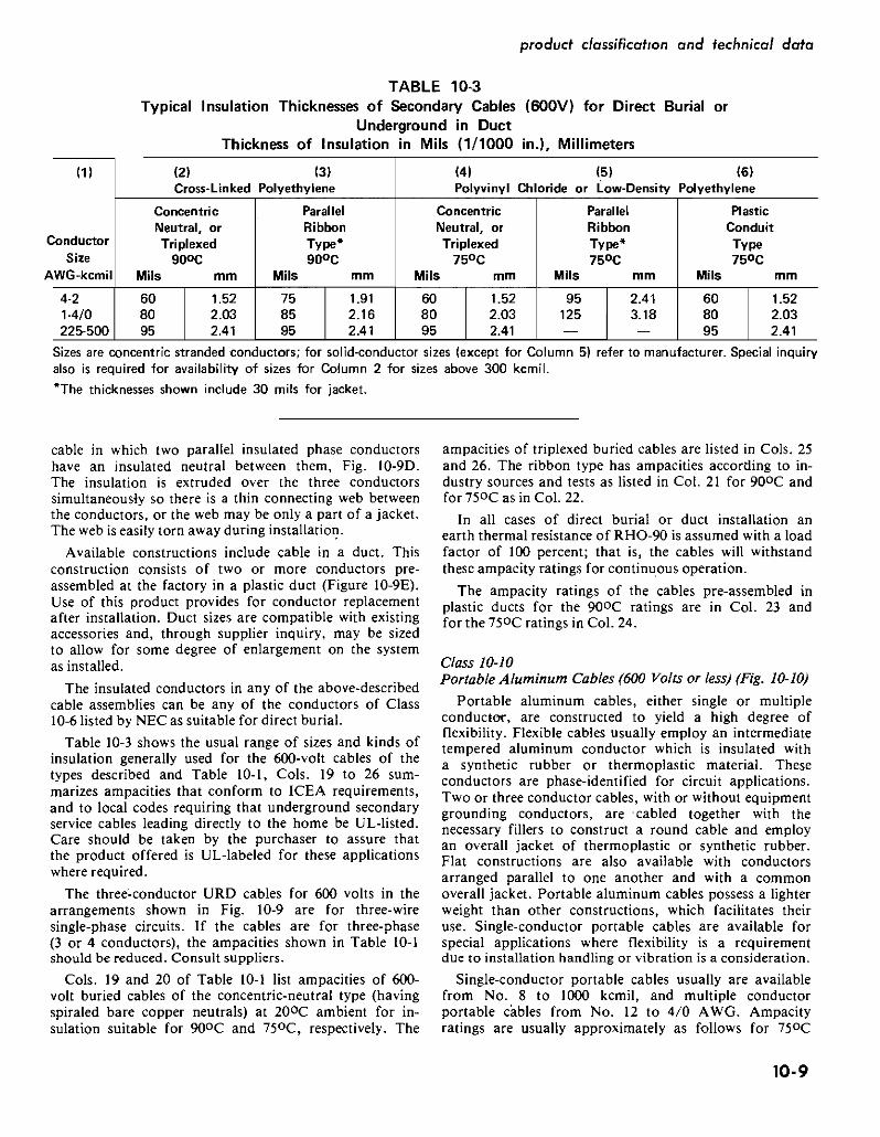
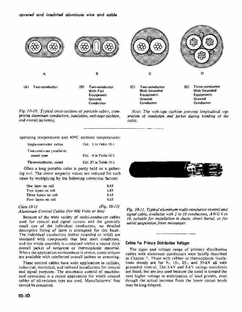
covered and insulated aluminum wire and cable
A S C D
AI Two~conductor (S) Twomiddotsonductor (C) Two~conductor (D) Three~c(JOductor
With Flat With Stranded With Stranded Equipment- Equipment~ Equipmentmiddot Ground Ground Ground Conductor Conductor Conductor
Fig 10-10 Typical cross-sections oj portable cables comshy Note The web-tape cushion prevents longitudinal sepshyprising aluminum conductors insulation web-tape cushion aration of insulation and jacket during bending oj the and overall jacketing cable
operating temperatures and 400C ambient temperatures
Single-conductor cables Col 3 in Table 10middot1
Two-conductor parallel or round type Col 4 in Table 10middot1
Three-condllctor round Col 27 in Table 10middot1
Often a long portable cable is partly held on a gathershying reel The above ampacity values are reduced for such cases by multiplying by the foUowing correction factors
One layer on roll 085 Two layers on roll 065 Three layers on roll 045 Four layers on roll 035
Class JOmiddotll (Fig 10-11) Aluminum Control Cables (for 600 Volts or less)
Because of the wide variety of multimiddotconductor cables used for control and signal circuits and the generally small size of the individual conductors no detailed descriptive listing of them is attempted for this book The individual conductors (either stranded or solid) are insulated with compounds that best meet conditions and the whole assembly is contained within a round thick overall jacket of neoprene or thermoplastic material Where the application environment is severe constructions are available with reinforced overall jackets or armoring
These control cables have wide application in utilities industrial municipal and railroad installations for control andmiddot signal purposes The automatic control of machinemiddot tool operations is a recent application for which control cables of oil-resistant type are used Manufacturers lists should be consulted
10middot10
Fig W-ll Typical aluminum multimiddotconductor control and signal cable available with 2 to 18 conductors A WG 9 to 14 suitable jor installation in ducts direct burial or jor aerial suspension jrom messenger
Cables For Primary Distribution Voltages The types and voltage range of primary distribution
cables with aluminum conductors were briefly described in Chapter 7 Those with rubber or thermoplastic insulamiddot tions mostly are for 5middot 15- 25- and 35middotkV all with grounded neutral The 3-kV and 8-kV ratings sometimes are listed but are less used because the trend is toward the next higher voltage in anticipation of load growth even though the actual increase from the lower circuit levels may be long delayed
Customarily primary-distribution insulated cables are voltage-rated on the basis on the phase-to-phase voltage of a three-phase circuit of which they are a part or would be a part if the three-phase circuit were complete Thus an insulated conductor of a single-phase branch circuit including a phase wire and a ground wire that is conshynected to the wye ground of a 25-kV three-phase wyeshygrounded circuit is still rated 25 kV although the actual rms kV of the single-phase circuit is only 25113 or 144 kV This notation applies principally to the single insushylated primary conductor of the two-conductor cable that supplies the single-phase transformer that feeds the secshyondary three-wire circuits
Cable descriptions in this book and in the literature disshytinguish between the insulation thicknesses required for high-voltage cables in circuits with grounded neutral and those with ungrounded neutral the latter requiring thicker insulation It is recognized however that there are other conditions than lack of neutral ground that may make a thicker insulation desirable To meet this condition the concept of grounded and ungrounded neutral is in the process of being eliminated as a sole criterion Instead the insulation thicknesses are assigned based on insulation level (AEIC 5 and 1987 NEC Table 310-13)
The selection of the cable insulation level to be used in a particular installation shall be made on the basis of the applicable phase-to-phase voltage and the general system category as outlined below
100 Percent Level-Cables in this category may be apshyplied where the system is provided with relay protecshytion such that ground faults will be cleared as rapidly as possible but in any case within one minute While these cables are applicable to the great majority of cable installations which are on grounded systems they may be used also on other systems for which the applicashytion of cables is acceptable provided middotthe above clearing requirements are met in completely de-energizing the faulted section
133 Percent Level-This insulation level corresponds to that formerly designated for ungrounded systems Cables it this category may be applied in situations where the clearing time requirements of the 100 percent levei category cannot be met and yet there is adequate assurance that the faulted section will be de-energized in a time not exceeding one hour Also they may be used when additional insulation strength over the 100 percent level category is desirable
173 Percent Level--Cables in this category should be applied on systems where the time required to deshyenergize a grounded section is indefinite Their use is recommended also for resonant grotindedsystems Conshysult the manufacturer far insulation thicknesses
bull Where additional insulation thickness is desired it shall be the same as for the 133 percent insulation level
product classification and technical data
The AElC reference to the preceding statement reshygarding insulation levels also includes the following
In common with other electrical equipment the use of cables is not recommended on systems where the ratio of zero to positive sequence reactance of the system at the point of cable application lies between -I and -40 since excessively high voltages may be encountered in the case of ground faults
Consideration of this requirement is in the province of the system electrical engineer
Tabular Voltages for Determining Insulation Thickness
For three-phase systems with grounded or ungrounded neutral the thickness values are those given in the respecshytive columns of Table 10-4 For three-phase delta systems where one leg may be grounded for periods of over one hour consult the 173 percent insulation level referenced above For single- and two-phase grounded systems multiply the voltage to ground by 173 and select thickness for that voltage in the grounded neutral column For a direct-current system up to and including 2000 volts consider it the same as a single-phase alternating-current system of the same rms voltage
Jacket Thickness
The insulation of unshielded cables may be of such quality that it will withstand all environmental conditions likely to be encountered such as moisture oil sunlight and abrasion in handling If so no jacket has to be added Several of the modem insulations meet this requirement but often a slight increase in insulation thickness is used to provide for expected surface wear and to equal other advantages obtained by a jacket
Shielded cables on tbe other hand unless protected by armor require a jacket not necessarily for improving surface quality but as protection for the insulation shieldshying The jacket material selected is the most suitable to meet conditions and usually it is a different compound than that of the insulation
The minimum thickness that qualifies a coating as a jacket on cables 2 kV andabove is 30 mils but the thickshyness also depends on diameter of the cable and voltage Jacket thicknesses have subsfantially become standardized as shown in Tables 10-5 and 10-6 The relative suitability of jackets of various materials can be determined from Table 8-4 Jacket thicknesses generally conform to those listed in Table 10-5 based on diameter and in Table 10-6 for single conductor cables based on A WG-kcmil size The individual conductors of a multi-conductor cable that has a jacket surrounding all conductors may have thinner jackets than those specified in Table 10-6 and conform to column 3 of Table 10-5 Column 4 lists thickness of the overall jacket
It is necessary to distinguish between an overall jacket
10middot11
covered and insulated aluminum wire and coble
Insulalion
Sirand
Jacket Metallic
Wire Shietd
Fig 0-12 Typical unshielded aluminum insulated prishy Fig 10-13 Typical 5 kV to 35 kV shielded insulated mary cable 5 k V with jacket primary cable
Note The metallic shielding may be tape as shown or helically applied closely spaced small wires
ICEA S-61-402 Table 4
Separator Tape
and a band of belt insulation as found in some kinds of cable such as for series-lighting circuits
Primary Unshielded Cables 3 kV and 5 kV
The 5 k V rating is the most used of this type Fig 10-12 If the insulation does not have a satisfactory surface for withstanding eilvironmental conditions a jackel is added
The usual cable construction without jacket comprises a Class-B stranded conductor (or it may be solid round in small sizes) a resistive conductor-shield and insulation of the thickness listed in Table 10-4 The insulation must be ozone and corona discharge-resistant suitable for wet or dry locations flame retardant and suitable for sunlight exposure although the latter two qualities may be obtained by jacketing if nOt a characteristic of the insulation The jacket if used must also be corona discharge resistant
Primary Cables with Insulation Shielding (to 35 k V)
The conditions that require shielding at 5 kV are stated in ICEA and pertain principally to single conshyductors at 133 percent insulation level or where cables are installed underground directly buried in ducts or in wet locations The shields are also required if the insulation or jacket is not one that protects against OzOne or its effects Insulation thicknesses are listed in Table 10-4 Generally except for the shielding the same
construction applies as for nonshielded cables Fig t0-13 is typical
Triplexed preas sembled cable or three-conductor cable either jacketed or in metallic armor of constructions preshyviously described is often used in the 5-kV-and-above ratings Figs 10-14 to -16 For ampacities see Table 10-7
Primary Interlocked-Armor Cables (Fig 0-16)
The description of interlocked corrugated armor used on cables for 600 volts (page 10-5) applies to cables for the primary voltages except for strand and insulation shielding requirements Howeer the impenrious seamless corrugated armor is not as yet available in as many voltage ratings or sizes as the interlocked armor Threeshyconductor armored cables are the most used Singleshyconductor cables are available for special applications with non-magnetic aluminum armor
The cables are available both with and without an exshytruded outer covering under the armor Either aluminum or steel armor is available Voltage drop at circuit power factors less than 100 percent is increased if steel armor is used but is negligibly affected by aluminum armor The ampacity rating of a three-conductor cable with aluminum corrugated armor is substantially the same and may be somewhat more than that of the insulated three-conductor cable in air the increase in area because of the corrugations and the closeness of the conductors to the armor both serve to increase the rate of heat transfer For ampacities see Table 10-7
10-12
product classification and technical data
TABLE 10-4 Insulation Thickness Inot including jackets) for HighmiddotVoltage Conductors in ThreemiddotPhase Systems with 100
and 133 Insulation Levels (or Grounded Neutral and Ungrounded Neutral respectively) Thickness in Mils (=11000 in)
Note The values in this table are obtained from ICEA or industry designations of thickness for the insulations named However because of variations of dates at which the values were issued and because of lack of uniformity of the size~steps slight variations occur Also some cable manufacturers issue specifications that in some respects show more favorable values The insulations are those used for ozone-resistant conditions In the 5OOO-volt class certain other insulations listed in Table 8-2 and 8~3 may be used but not necessarily at the listed thickness
I ButylEPR Silicone (SAl L XLPE or PE(1)Voltage
(21 Unmiddot Grounded Grounded UnmiddotUnmiddot Grounded orand Size Grounded Neutral Grounded Neutral Grounded UngroundedGroundedAWG
Neutral Neutral Neutral NeutralNeutraland kcmit mils mm mils mm mils mm mils mm mils mmmils mm mils mm
UNSHIELDED 2OO1middot5000V(31
90 90 229 394 155110 279 110 279 229 155 394 155 394 225middot500
8middot40 So 90 432 432
525-1000 120 305 305 229 229 170 432 170120 70
90 90 170 170130 330 130 330 229 229 432 432 170 432
SHIELDED 2oo1-5000v
8-410 39490 229 90 229 90 229 90 229 155 155 394 225middot500 432 525middot1000
90 229 90 229 90 90 229 170 432 170229 22990 90 229 90 229 229 170 432
5OO1middot8000V 90 432 170
I 483 250292115 140 356 115 140 356 190 483
525-1000 115 6middot500 292 bull
292 483 250140 356 115 292 bull 140 356 190 483 8001middot150ooV I
2middot1000 175 445 175 445 295 749 1middot1000 215 546 215 1067420546
15001middot25000V 1middot1000 876260 660 345 260 660 345 876 4551156
25OO1-28000V 1middot1000 711 280 711280 711 420 711 420 705001 12
28001middot350ooV 110-1000 345 8761 420 711 345 876 420 711
2middotConductor Concentrid41 Helical Bare Grounded Neutral
5kV XLPE HPE 4middot350 90 90 15 kV
4middot350 175 175 25kV
2-350 260 260 35 kV
10-350 345 345
NOTE The difference of thickness between unshielded and shielded 5 kV cables using XLPE or PE insulations reflects the fact that the unshielded cable has a potential distribution not as even as that of the shielded cable
See page 10-15 for additional notes
Required by specification to have an outer jacket maxishymum 3phase voltage for 133 insulation level 3000V
JACKET THICKNESS AWG or kcmil Mils mm 8middot6 30 076 4-210 45 114 30-1000 65 165
Required by specification to have an outer jacket
JACKET THICKNESS AWG or kcmil Mils mm 8-1 45 114 10-40 65 165 225-750 65 165 1000 95 241
10middot13
covered and insulated aluminum wire and cable
TABLE 1()5 Jacket Thicknesses for Single- and Multiple-Conductor
Power cables According to Diameter Under Jacket For all uses Conduit Tray Trough Underground Duct Aerial and
Oirect Burialt but does not include Communicationor Portable Cables
Jacket Thickness Sing1c-conductor Cable Multiple-cQtlductor Cables
ill (21 (31 (41
Calculated Diameter of Cable Undef Jacket Noll$hielded Shieldedmiddot Individual
Conduct t Overall inche$ mm mils mm mils mm mils mm mils mm
0250 or I 635 or less 15 038 45 114 15 038 45 114 0251middot0425 638-1080 30 076 45 114 25 064 45 114 0426-0700 1082middot1778 45 114 60 152 30 076 60 152 0701middot1500 1771middot3810 65 165 60 203 60 127 60 203 1501middot2500 3813-6350 95 241 110 279 60 203 110 279 2501 and larger 6353 ond lorger 125 318 140 356 140 356
+ Under common jacket
t These thicknesses apply to jackets only and do not apply to colored coatings used for the purpose of circuit identification on the individual conductors of multiple-conduClor cables
+Single-conductor cables in sizes 9 AWG and smaller shall not be used for direct earth burial _ In calculating the diameter under the jacket of single-conductor shielded conductors that are part of a multi-conductor cable
add 45 mils to the insulation thickness to allow for thickness of the inSUlation shield Also add the thlckness of the separator and strand tapes Eqs 9-3 9-4 and 9-5 provide a means for calculation of diameter provided Di is the inside diameter of the jacket instead of the outer sheath Two-conductor cables for direct burial having helical bare copper wire ground conductors have an outer protective covering of conducting material that also serves as an insulation shield The layer is not less than 30 mils thick NOTE-For flat twin cable use the calculated major core diameter under the jacket to determine the jacket thickness from Column 4 Source ICEA 5-61-402
TABLE 1()6 Jacket Thicknesses for Single-Conductor Power Cables According to AWGmiddotkcmil Sizes
For all uses Conduit Trays Troughs Underground Duct Aerial and Direct Surial not including Communication or Portable Cables It is assumed that the jacket material is compatible with the insulation for the designated kV ratings These thicknesses also apply to single-conductor cables if they are triplexed but they do not necessarily apply to the cables that are a part of a three-conductor cable for which the thickness may be according to column (3) of Table l()S
Volts
Percent Insulation
Level 30 (0761
Thickness of Jacket Mils (= 111 000 In) (mm)
45 (114) 60 (152) 65 (165) 80 (203) 110 (279)
UNSHIELDED 2001 5000 100 amp 133 8middot 6 4 bull 210 310 bull 1000
SHIELDED
2001 5001
8001
5000
8000
bull 15000
100 amp 133 100 133 100 133
8 6 bull 20 6 - IO 6 bull 2
30 bull 1000 20 bull 1000 1 bull 750 2 bull 750 1 middot 800
1000 1000
750 bull 1000
15001 bull 25000 100 133
1 1
middot 500 middot350
600 bull 1000 400 bull 1000
25001 bull 28000 100 1 bull 500 800 1000
28001 bull 35000
Source ICEA S-61-402
100 I
IO 350 400 bull 1000
10-14
80 Messenger
produd classification and technical data
TABLE 10-4 NOTES
(1) The characteristics for the kinds of insulation shown are listed in Tables 8-2 8-3 and 84 for which also see rated temperatures (2) If insulation is rated acoording to percent insulation level use column grounded neutral for 100 level and column for
ungrounded neutral for 133 level
(3) Solid dielearlc insulated conductors operated above 2000 volts generally fequlre shielding under the NEe Conditions under which shielding is not required in the 2000-8(100 volts range are detailed in NEe Section 310~6
(41 The cables listed in the main body of the table are generally available in the sizes shown as single conductors or cabled for aerialshymessenger support or in tray or duct~ and with some insulations are suitable for direct burial The two-conductor concentricshyneutral cables are mostly used for direct burial but they also may be used in duct or be aerial-supported The insulation thickness tOt coaxial cables (in which the neutral is tubular) are Similar
Fig 10-14 Typical pre-assembled triplexed 5-k V to 25middot kV shielded primary cable bound to composite aluminumshysteel (ACSR or A CSRlAW) or aluminum-alloy messenger with aluminum tape A fourth insulated neutral may be in~luded ifrequired
The construction of each conductor is similar to that deshypicted in Fig 10-13 Also available with one or two phase conductors
For certain sizes reverse-lay may be obtained (see Fig 10-3) Also for parallel lay (not Iriplexed) field-spinning equipment is available so that the assembly with lashing wire may be performed at the site
Similar pre-assembled triplexed (or parallel) cables are available without insulation shielding to 5 k V
Primary Cables for Underground Residential Distribution-URD
Directly buried URDU D style cables are increasingly being used as main-line threemiddotphase distribution feeders
However by far the most used primary cables for URD are those thaI supply singlemiddot phase primary voltage to the singlemiddotphase 1ransformers supplying 120middot240 V three-wire circuits to the residences or other usepoims in the area These singlemiddotphase primary cables are of
Shlald
Fig 10middot15 Typical three-conductor 5-kV to 35-kV shielded primary cable in jacket
The construction of each conductor is similar to tfuJt deshypicted in Fig 0middot3 Triangular fillers in the interstices aid in forming a cylindrical exterior that still will withstand bending from reel Bare grounding conductors may be used in the interstices if required
the two-conductor type One conductor is an insulated phase wire The other is either a copper-wire concentric neutral conductor of equal conductivity to that of the aluminum insulated conductor Fig 10-17 or a concentric flat strap neutral Fig 10-18 particularly adapted to conshyditions where substantially full metallic coverage is desired These copper neutrals are directly in contact with the ground when buried
The phase conductors of these cables have semimiddot conducting strand shielding and semiconducting comshypound undernea1h the concentric wires or raps to serve as an insulation shield
The insulation thickness around the phase conductor is generally the same as listed in Table 10-4 For ammiddot pacities see Tables 1Omiddot9A and 10middot9B
10middot15
covered and insulated aluminum wire and cable
High Voltage Primary Cables
Aluminum cables are commonly available through 115 kV levels Advances in materials and manufacturing expertise have resulted in available cables in this and higher voltage levels While previous cable constructions employed paper insulation with some gas-filled designs todays market offers some cables of this type with solid dielectric insulations Polyethylene and crosslinked poly ethylene and similar materials are being employed in cable designs Information concerning availability and design should be directed to individual cable manushyfacturers
As typical of such construction a IISmiddotkV 500middotkcmil aluminum cable for direct burial with strand and insulation shielding has 0740 in XLPE insulation thickshyness (0525-in for 69 kV) with a 0140middotin thick PVC jacket and 290middotin overall diameter (237 in for 69-kV)
Ampacity of High Voltage Aluminum Cables
The ampacity values listed in Table 10-7A -B and -C for the designated cable types and installation conditions mostly are those listed in ICEP Pub 46-426 Vol II for aluminum as explained in Chapter 9 applying to rubbershyor thermoplastic-insulated cables The insulation is asshysumed to have a power factor of 0035 dielectric constant of 45 and thicknesses for the various voltages that were listed in ICEA Standards in 1962 when the ampacity values were published Cables directly buried or in under-
Insulation Conductor Shield
c~~~~~orlnSluai~~ndTape Shield
(OPliOr 1
11 FillersArmor(Inlerlocklng)
Tape
Fig 1()16 Three-conductor shielded cable 5 kV to 15 k V with interlocked or impervious corrugated steel or aluminum armor
Bare Coated Copper Neutral StrandInsulation
Shield
Fig ]()17 Typical 5 to 35 kV two-conductor concentricshywire neutral primary cable for direct burial duct or aerial application
Bare Coated Strand Copper Neutral Insulation Shield
Conductor
Fig ]()18 Typical 15middot35 kV two-conductor concentric flnt-strap neutral primary cable for direct burial or duct
ground ducts are assumed to be in circuits of 100 load factor and RHO-90 earth resistivity For 75 load factor direct burial increase ampacity by 6 or for duct 3 and for 50 ]f by 14 and 6 respectively Table 10shy7 is based on 40C ambient for cables in air and 20C ambient if underground Adjustment factors for other ambients are in Table 10-8
Separate tables 10-9A and JO-9B list the arnpacities of concentric-neutral primary cables for direct burial in duct at 200C ambient and also for installation of the cables in air or in duct in air at 400C ambient as necessary for leads into air from an underground installation Table JOmiddot9A also includes ampacities for 35 kV cable when buried directly or in duct
Inasmuch as ICEA and industry standards now allow some reduction of thickness of certain kinds of insulations as compared with the values that prevailed in 1962 and also because most insulations have a luwer pf than 0035
10middot16
1
product classification and technical data
TABLE 10-7A Typical Ampacities of 5 kV Cables with Aluminum Conductors
of Various Types and for Various Installation Conditions
5 kV in Air 4oC 5 kV in Duct 20C 5 kV Directly Buried 20C Ambienl Onshieldedt
Conductor Grounded or Neutral RHO-go 100 LF RHO-SO 00 IF Size Ie in Ai
~~of u Th~ ~nd Interlocked j Nu 1No1
AWG lof3C Armor kernil
1 of 3C lC Triplexed Three Condo
I lC Triplexed
lC of 3 lof3C leof 3
(1) (Z) (3) (4) (5) (6) m (8) 19)
] 7~ 19oC 7SoC WC 175C 190C75C looc SoC 9OC 7SC 90degC 75degC WC 90C 7SC i 75 looC
bull 55 64 44 51 39 46 - - 56 62 45 42 46 n 84 65 72 6 73 85 59 69 53 61 54 63 73
1 60 55 61 9B ____ 108 94 92
4 97 113 78 9shy ii) 81 71 8 96 78 72 80 127 14U lU8 119 2 129 12 9 108 95 125 1 103 94 -~ 163 180 139
14 144 12 113 131 143 119 131 109 120 184 20 158 110
~ 167 145 131 150 163 136 15e 1151 138
-~~~ 231 180 210 lt 3 168 153 174 187 205_ 156 17 143 156 26 3in 26 192 224 166 194 272- shy ~ i~-~~lmiddot~ --yen50~ 164 --shy 180
j1E~299
~fi410
=i ~ -1~
2000
2681 3 224 262 19 224 7 206 307 31 2 214 50 I 21 256 1 269 296 22 20 228 335
3101 43 364 265 309 I 21 320 321 360 276 304 25 278 403 444 349 466 544 458 330 385 I 335 398 401 4421338 _~ 308 340 490 540 424 606 70 42 45 43 51 05 556 425 386 426 605 667 525 579 73J 8531 716 i 499 584 515 605 59
I 65 I 49 546 447 495 i 706 778 5 b72
840 781
9 1103 73 90 g 10391 1216 I 79 8801 930 1128 1321 85 9401 990 1094
j notes ltIay be found under Table 10-7C Source ICEA P-46-425
TABLE 10-7B Typical Ampacities of 15 kV Cables with Aluminum Conductors
of Various Types and for Various Installation Conditions
Size AWG kcmil
11 10 10
2gt0 350
=ii 1500 1750
2000
I
I
15 leV in Air 40degC Ambient 15 kV in Duct 20degC 15 leV Directly Buried 20degC Ambrent-Shielded AmbjentmiddotShidded
Shiekted RH~90 10 LF RHOmiddot90 100 LF Grounded Neutral Grounded Neutta Grounded Neutral
Ilnwrlocked
Armor TripMxed TareeCond iThne Condo Triplexed ThreeCond Triplexed
1e in Air leof3 1 of 3C 1 of 3C Ie 1C of3 1 of 3C lC 1C of 3
t1) (2) (31 (4)44 (51middot 161 i1I 18)middot 191
7SoC goc 75degC 9(ldegC 75degC 90degC i 75degC 90aC 75degC deg 90 C 7SoC ~centC 75degC 90degC 7SoC SOoC Soc oooe
i
130 152 115 135 109 128 bull 95 119 126 139 110 1121 106 117 149 154 133 147
125 144 159 125 38 120 133 70 187 152 167 170 2Q2 3 178 143 I bullbull 121 158 164 181 142 157 137 101 bull 213 I 199 232 175 205 164 192 146 183 181 rob 1 I
bull 1 1 12 2 lt44 211 229 268 202 237 189 221 168 I 208 213 23 184 1203 117 196 250 2 220 24
u 302 240 ~ 216
LLL LOU
293 343 258 26 21 29 ~~ i~ 221 l44 bull u 1 CJtJI
363~=i 312 294 344 =i 332 323 35 266 294 378 417 335 369 395 322 405 447
587 687 591 459 639 529j
541 412 1 44U 14 4 bull 2
810 I
905 I 1060
I bullbull 20 U_ 994 - 1165 776 859 887 967
lUlb I 827 917 945 1047
Applicable nOtes may be found under Table lO-7C Source lCEA P-46-426
10middot17
covered and insulated aluminum wire and cable
the ampacity listings of Table 10-7 are conservative for some applications and cable manufacturers may offer moderately larger ampacities However as previously stated the 0035 pf value is an ICEA estimate of what the pf may become after many years of exposure and use
The ampacity ratings of the types shown in Table 10-7 for 35 kV and 46 kV are practically the same as those of 25 k V for installations in air and only up to about 2 pershycent less for direct burial hence values for 35 k V and 46 kV are omitted from Table 10-7 Also inasmUCh as
high-voltage cables are not used in rigid conduit to the extent formerly (cables in interlocked armor have largely superseded them) ampacities for high-voltage conduit inshystallations are not listed Ampacities to 35 kV conduit installations are listed in NEC Article 310middot Tables along with ampacities for cables in fiee air direct burial and unlterground ducts For both underground duct and direct burial special attention must be paid to the number of circuits andor ducts
TABLE 10-7C Typical Ampacities of 25 kV Cables with Aluminum Conductors
of Various Types and for Various Installation Conditions
Conductor $iIe
AWG kem
2 1
lIU 210 ~U
40
2 350 500 750
1000
bull
25 kV in Ouct 20degC 1 25 kV Directfy Buried 20degC 25 xV in Air 40degC Ambient Ambient-Shielded AmbientShielded
Shielded RHO-90 100 LF RHO-90 100 LF Grounded Neutral Grounded Neutral Grounded Neutral
I
Triplaxed Three Cond Triplexed Three Cond Triptexed
i 1C in Air I lC al3 1of3C i lC I
1Cof 3 1 of 3C 1C lC al3
(1) 12) 131 151 16) m IS) (9)
175degC gooC 7SoC 90degC i75degC 19ooc 1Soc gooC 7SQC 90degC i 1SeC gooC 1SC 9OC 75degC i goC
- - i - - - - - --= - I _ bull _ -= - - - I _ 148 173 135 158 127 149 143 t57 126 139 12 I 134 t6 177 148 I t63 170 198 t55 182 iii 170
163 180 143 _tss L 1 8 152 Ull4 203 168 _86 95 228 178 _208 195 185 2M 163 H)I) 6 172 ~ 231 191 1211 22 204 240 1 203 211 233 18 204 196 239 264 217 240
259 _303 235 1 276 217 ~55 240 265 2tO 232 2 222 211 300 241 273
ampgt4 20U I uti 240 2~2 263 291 i 229 253 220 243 I 298 329 270 298 353 412 318 373 292 ~ 318 bull 35t I 275 304 2S4 292 360 i 325 360 440 514 394 463 359 22 3S8 428middot 332 367 319 353 439 394 435 567 i OW I 454 bull bull 537 i 40B 392 433 537 m 589 692 532 i 625 587 I 626 I 467 5t6 450 498 541 708 558 617 Tti I 639 706 720 796 lEiS 004 701 n4 790 873
~ -00 I I 757 i~ 852 942 1203 I 806 I L 907 L 1000
SOurce JCEA P-45-426
FOOTNOTES FOR TABLES lo-7A middot7B and middot7C Allowable ampacities are the maximum continuous ampacities under stated conditions All ampacity values except as noted are from ICEA Publication No P46-426 Vol II for the nearest comparable cables See Tabte 10-9A and 9B for ampacity values of twoshyconductor concentrlc~neutf81 cables for direct burial in duct and in air Additional ampacity ratings and information on ampacitY calculations are available from leEA P-53-426 (NEMA WCSO) and Tables in NEe Article 310
The Ampacity listing for single-conductor (lIe) cables assume$ they are $paced 75 in ~ntermiddotto-center or at lea$t one cable diameter apart surface~to-$Urface that shield is grounded at only one point With negligible $hield losse$
These values are taken from an industry $OUfCe The armor is of aluminum
tFor ampaeities of shielded 5 kV cables refer to cable manufacturer Shielded cables usually have slightly more ampacity becau$e the metallic $hielding tend$ to increase the radial therma1 hat trensfer from the conductor
10middot18
produd c1(gtssification and technical data
TABLE 10-8 Adjustment Factors for Ampacity Values in Table 10-7 for
Variations of Ambient Temperature
The following factorsmiddot may be used to adjust ampacities for various ambient temperatures
If me ampacity is known for Conductor Temperature 900( 750 C 9()OC 750 C
Ambient T emperatur 400C 400 C 200 C 200C
New Ambient Temperature Multiplication Factor (MF)
MUltiply by the indicated acc 134 146 113 117 factor to obtain the new IOOC 126 136 107 109 ampacity for the new 200C l1e 125 100 100 ambient temperature 300c 109 113 093 089
400C 100 100 500C 089 0e5
For example A cable may have known ampacity of 100 amps when operating at a 9()OC conductor temperature in a 400c ambient The same cable operated at 900c conductor temperature in a 3QoC has an ampacity of 109 amps while in a 500( ambient 89 amps
-Table factors are derived from the following equation
MF=
12 = I(MF)
where II ~ ampacity from tables at ambient TAl
12 = ampacity at desired ambient TA2
TC conductor temperature in degrees C
TA1 = ambient from tables in degrees C
TA2 = desired ambient in degrees C
TC-TA
10middot19
covered and insulated aluminum wire and coble
TABLE 10-9A Ampacities of TwomiddotConductor ConcentricmiddotNeutral +Underground Distribution Cable for Direct Burial
and for Installation in Buried Duct (see Figs 10middot17 and 10middot18)
Ambient Temperature 20degC Load Factor 100 Percent The 7SC ratings apply to cable with Hi-Mol Polyethylene Insulation
The 90C ratings apply to cables with Cross-Linked Polyethylene Insulation
The left-hand entries of any pair are ampacities when directly buried The right-hand entries are ampacities when in duct
Conductor 15 kV
90C 75C 9OC
132-88 116-83 128-91 174-115 152-108 168-119 199-132 175-124 193-137 226-150 198-141 218-155 256-172 225-161 248-177
2Sk~ J 35 kVSize 5 kVI AWG or kcmil
4 2 1 110 20 30 40 250 300
75C i_90OC75C bull 75O C
T90
0 C
- _
120-80 I 14~~105 bull
-~
165-115158-104 I 181-120 165-120 205-136 I 190-135 232-156 264middot177 304middot205 336-229 379-260
215-155 291-195 258middot182 284-201 245middot170 335-226 294middot209 324-230 280-200 370-252 327-233 360-257 310middot220 418middot287 366middot264 403middot291 350-250
i
190-135 210-150 190-135 210-150I240-170 215middot155 240middot170 275-195 245middot170 275-195 315middot225 280-200 315-225 350middot250 395-280
Ampacity vlues for 5 kV and 15 kV cables are from ICEA tables those 25 kV and 35 kV are from other industry sources
Multiplying Correctionmiddot Factors for Load Factors of 75 and 50 percent
75 percent Load Factor 50 percent Load Factor
15 kV 108 104 116 107 25kV 108 104 116 107
Cable Rating Cable Cable in Cable Cable in kV Buried Duct Buried Duct
5kV L 109 104 116
-- I~~- ilL +Refer to The Aluminum Associations Aluminum Underground Distribution Reference Book for additional typical information
10-20
product classification and technical data
TABLE 10-9B Ampacities of Two-Conductor Concentric-Neutral
Underground Distribution Cable when Installed in Air or in Duct in Air
(usually as leads from an underground buried or duct installation)
(see Figs 10-17 and 10-18)
Ambient Temperature 40deg C The 75C ratings apply to cable with Hi-Mol Polyethylene Insu lation The 90degC ratings apply to cable with Crossmiddot Linked Polyethylene Insulation
The left-hand entries of any pair are ampacities for cable only in air The rightmiddothand entries are ampacities when cable is in duct in
air
Cond 5kV 15kV AWGkcmil 75centC 90degC 75C gooC
4 75-65 90middot76 81middot68 95middot79 2 103-86 120middot100 107-88 125middot103 1 119-99 139middot116 124middot102 145middot119 110 137-112 160middot131 142middot116 166-135 20 159middot128 186middot149 163-132 190middot154 30 181-146 211middot170 187middot151 218middot176 40 212-169 247-197 217-172 i 253middot201 250 238-188 278middot219 244-1931285225 300 273middot214 319middot250 278middot218 324middot254
Ampalty values are from ICEA tables
10middot21
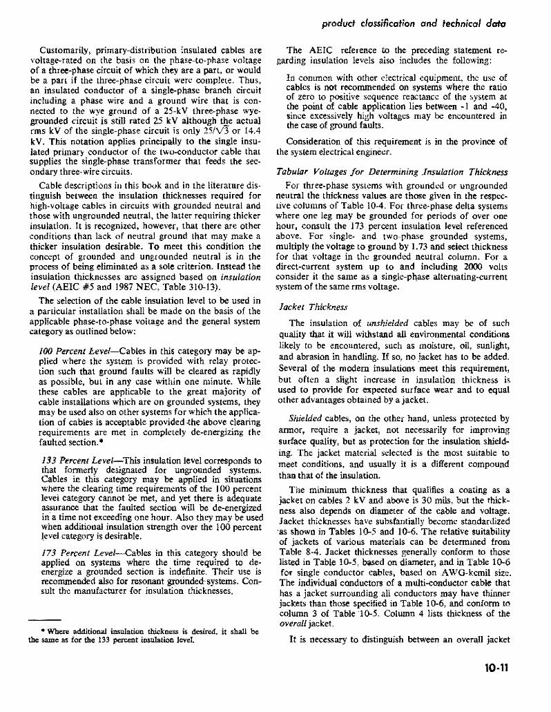

covered and insulated aluminum wire and coble
Insulalion
Sirand
Jacket Metallic
Wire Shietd
Fig 0-12 Typical unshielded aluminum insulated prishy Fig 10-13 Typical 5 kV to 35 kV shielded insulated mary cable 5 k V with jacket primary cable
Note The metallic shielding may be tape as shown or helically applied closely spaced small wires
ICEA S-61-402 Table 4
Separator Tape
and a band of belt insulation as found in some kinds of cable such as for series-lighting circuits
Primary Unshielded Cables 3 kV and 5 kV
The 5 k V rating is the most used of this type Fig 10-12 If the insulation does not have a satisfactory surface for withstanding eilvironmental conditions a jackel is added
The usual cable construction without jacket comprises a Class-B stranded conductor (or it may be solid round in small sizes) a resistive conductor-shield and insulation of the thickness listed in Table 10-4 The insulation must be ozone and corona discharge-resistant suitable for wet or dry locations flame retardant and suitable for sunlight exposure although the latter two qualities may be obtained by jacketing if nOt a characteristic of the insulation The jacket if used must also be corona discharge resistant
Primary Cables with Insulation Shielding (to 35 k V)
The conditions that require shielding at 5 kV are stated in ICEA and pertain principally to single conshyductors at 133 percent insulation level or where cables are installed underground directly buried in ducts or in wet locations The shields are also required if the insulation or jacket is not one that protects against OzOne or its effects Insulation thicknesses are listed in Table 10-4 Generally except for the shielding the same
construction applies as for nonshielded cables Fig t0-13 is typical
Triplexed preas sembled cable or three-conductor cable either jacketed or in metallic armor of constructions preshyviously described is often used in the 5-kV-and-above ratings Figs 10-14 to -16 For ampacities see Table 10-7
Primary Interlocked-Armor Cables (Fig 0-16)
The description of interlocked corrugated armor used on cables for 600 volts (page 10-5) applies to cables for the primary voltages except for strand and insulation shielding requirements Howeer the impenrious seamless corrugated armor is not as yet available in as many voltage ratings or sizes as the interlocked armor Threeshyconductor armored cables are the most used Singleshyconductor cables are available for special applications with non-magnetic aluminum armor
The cables are available both with and without an exshytruded outer covering under the armor Either aluminum or steel armor is available Voltage drop at circuit power factors less than 100 percent is increased if steel armor is used but is negligibly affected by aluminum armor The ampacity rating of a three-conductor cable with aluminum corrugated armor is substantially the same and may be somewhat more than that of the insulated three-conductor cable in air the increase in area because of the corrugations and the closeness of the conductors to the armor both serve to increase the rate of heat transfer For ampacities see Table 10-7
10-12
product classification and technical data
TABLE 10-4 Insulation Thickness Inot including jackets) for HighmiddotVoltage Conductors in ThreemiddotPhase Systems with 100
and 133 Insulation Levels (or Grounded Neutral and Ungrounded Neutral respectively) Thickness in Mils (=11000 in)
Note The values in this table are obtained from ICEA or industry designations of thickness for the insulations named However because of variations of dates at which the values were issued and because of lack of uniformity of the size~steps slight variations occur Also some cable manufacturers issue specifications that in some respects show more favorable values The insulations are those used for ozone-resistant conditions In the 5OOO-volt class certain other insulations listed in Table 8-2 and 8~3 may be used but not necessarily at the listed thickness
I ButylEPR Silicone (SAl L XLPE or PE(1)Voltage
(21 Unmiddot Grounded Grounded UnmiddotUnmiddot Grounded orand Size Grounded Neutral Grounded Neutral Grounded UngroundedGroundedAWG
Neutral Neutral Neutral NeutralNeutraland kcmit mils mm mils mm mils mm mils mm mils mmmils mm mils mm
UNSHIELDED 2OO1middot5000V(31
90 90 229 394 155110 279 110 279 229 155 394 155 394 225middot500
8middot40 So 90 432 432
525-1000 120 305 305 229 229 170 432 170120 70
90 90 170 170130 330 130 330 229 229 432 432 170 432
SHIELDED 2oo1-5000v
8-410 39490 229 90 229 90 229 90 229 155 155 394 225middot500 432 525middot1000
90 229 90 229 90 90 229 170 432 170229 22990 90 229 90 229 229 170 432
5OO1middot8000V 90 432 170
I 483 250292115 140 356 115 140 356 190 483
525-1000 115 6middot500 292 bull
292 483 250140 356 115 292 bull 140 356 190 483 8001middot150ooV I
2middot1000 175 445 175 445 295 749 1middot1000 215 546 215 1067420546
15001middot25000V 1middot1000 876260 660 345 260 660 345 876 4551156
25OO1-28000V 1middot1000 711 280 711280 711 420 711 420 705001 12
28001middot350ooV 110-1000 345 8761 420 711 345 876 420 711
2middotConductor Concentrid41 Helical Bare Grounded Neutral
5kV XLPE HPE 4middot350 90 90 15 kV
4middot350 175 175 25kV
2-350 260 260 35 kV
10-350 345 345
NOTE The difference of thickness between unshielded and shielded 5 kV cables using XLPE or PE insulations reflects the fact that the unshielded cable has a potential distribution not as even as that of the shielded cable
See page 10-15 for additional notes
Required by specification to have an outer jacket maxishymum 3phase voltage for 133 insulation level 3000V
JACKET THICKNESS AWG or kcmil Mils mm 8middot6 30 076 4-210 45 114 30-1000 65 165
Required by specification to have an outer jacket
JACKET THICKNESS AWG or kcmil Mils mm 8-1 45 114 10-40 65 165 225-750 65 165 1000 95 241
10middot13
covered and insulated aluminum wire and cable
TABLE 1()5 Jacket Thicknesses for Single- and Multiple-Conductor
Power cables According to Diameter Under Jacket For all uses Conduit Tray Trough Underground Duct Aerial and
Oirect Burialt but does not include Communicationor Portable Cables
Jacket Thickness Sing1c-conductor Cable Multiple-cQtlductor Cables
ill (21 (31 (41
Calculated Diameter of Cable Undef Jacket Noll$hielded Shieldedmiddot Individual
Conduct t Overall inche$ mm mils mm mils mm mils mm mils mm
0250 or I 635 or less 15 038 45 114 15 038 45 114 0251middot0425 638-1080 30 076 45 114 25 064 45 114 0426-0700 1082middot1778 45 114 60 152 30 076 60 152 0701middot1500 1771middot3810 65 165 60 203 60 127 60 203 1501middot2500 3813-6350 95 241 110 279 60 203 110 279 2501 and larger 6353 ond lorger 125 318 140 356 140 356
+ Under common jacket
t These thicknesses apply to jackets only and do not apply to colored coatings used for the purpose of circuit identification on the individual conductors of multiple-conduClor cables
+Single-conductor cables in sizes 9 AWG and smaller shall not be used for direct earth burial _ In calculating the diameter under the jacket of single-conductor shielded conductors that are part of a multi-conductor cable
add 45 mils to the insulation thickness to allow for thickness of the inSUlation shield Also add the thlckness of the separator and strand tapes Eqs 9-3 9-4 and 9-5 provide a means for calculation of diameter provided Di is the inside diameter of the jacket instead of the outer sheath Two-conductor cables for direct burial having helical bare copper wire ground conductors have an outer protective covering of conducting material that also serves as an insulation shield The layer is not less than 30 mils thick NOTE-For flat twin cable use the calculated major core diameter under the jacket to determine the jacket thickness from Column 4 Source ICEA 5-61-402
TABLE 1()6 Jacket Thicknesses for Single-Conductor Power Cables According to AWGmiddotkcmil Sizes
For all uses Conduit Trays Troughs Underground Duct Aerial and Direct Surial not including Communication or Portable Cables It is assumed that the jacket material is compatible with the insulation for the designated kV ratings These thicknesses also apply to single-conductor cables if they are triplexed but they do not necessarily apply to the cables that are a part of a three-conductor cable for which the thickness may be according to column (3) of Table l()S
Volts
Percent Insulation
Level 30 (0761
Thickness of Jacket Mils (= 111 000 In) (mm)
45 (114) 60 (152) 65 (165) 80 (203) 110 (279)
UNSHIELDED 2001 5000 100 amp 133 8middot 6 4 bull 210 310 bull 1000
SHIELDED
2001 5001
8001
5000
8000
bull 15000
100 amp 133 100 133 100 133
8 6 bull 20 6 - IO 6 bull 2
30 bull 1000 20 bull 1000 1 bull 750 2 bull 750 1 middot 800
1000 1000
750 bull 1000
15001 bull 25000 100 133
1 1
middot 500 middot350
600 bull 1000 400 bull 1000
25001 bull 28000 100 1 bull 500 800 1000
28001 bull 35000
Source ICEA S-61-402
100 I
IO 350 400 bull 1000
10-14
80 Messenger
produd classification and technical data
TABLE 10-4 NOTES
(1) The characteristics for the kinds of insulation shown are listed in Tables 8-2 8-3 and 84 for which also see rated temperatures (2) If insulation is rated acoording to percent insulation level use column grounded neutral for 100 level and column for
ungrounded neutral for 133 level
(3) Solid dielearlc insulated conductors operated above 2000 volts generally fequlre shielding under the NEe Conditions under which shielding is not required in the 2000-8(100 volts range are detailed in NEe Section 310~6
(41 The cables listed in the main body of the table are generally available in the sizes shown as single conductors or cabled for aerialshymessenger support or in tray or duct~ and with some insulations are suitable for direct burial The two-conductor concentricshyneutral cables are mostly used for direct burial but they also may be used in duct or be aerial-supported The insulation thickness tOt coaxial cables (in which the neutral is tubular) are Similar
Fig 10-14 Typical pre-assembled triplexed 5-k V to 25middot kV shielded primary cable bound to composite aluminumshysteel (ACSR or A CSRlAW) or aluminum-alloy messenger with aluminum tape A fourth insulated neutral may be in~luded ifrequired
The construction of each conductor is similar to that deshypicted in Fig 10-13 Also available with one or two phase conductors
For certain sizes reverse-lay may be obtained (see Fig 10-3) Also for parallel lay (not Iriplexed) field-spinning equipment is available so that the assembly with lashing wire may be performed at the site
Similar pre-assembled triplexed (or parallel) cables are available without insulation shielding to 5 k V
Primary Cables for Underground Residential Distribution-URD
Directly buried URDU D style cables are increasingly being used as main-line threemiddotphase distribution feeders
However by far the most used primary cables for URD are those thaI supply singlemiddot phase primary voltage to the singlemiddotphase 1ransformers supplying 120middot240 V three-wire circuits to the residences or other usepoims in the area These singlemiddotphase primary cables are of
Shlald
Fig 10middot15 Typical three-conductor 5-kV to 35-kV shielded primary cable in jacket
The construction of each conductor is similar to tfuJt deshypicted in Fig 0middot3 Triangular fillers in the interstices aid in forming a cylindrical exterior that still will withstand bending from reel Bare grounding conductors may be used in the interstices if required
the two-conductor type One conductor is an insulated phase wire The other is either a copper-wire concentric neutral conductor of equal conductivity to that of the aluminum insulated conductor Fig 10-17 or a concentric flat strap neutral Fig 10-18 particularly adapted to conshyditions where substantially full metallic coverage is desired These copper neutrals are directly in contact with the ground when buried
The phase conductors of these cables have semimiddot conducting strand shielding and semiconducting comshypound undernea1h the concentric wires or raps to serve as an insulation shield
The insulation thickness around the phase conductor is generally the same as listed in Table 10-4 For ammiddot pacities see Tables 1Omiddot9A and 10middot9B
10middot15
covered and insulated aluminum wire and cable
High Voltage Primary Cables
Aluminum cables are commonly available through 115 kV levels Advances in materials and manufacturing expertise have resulted in available cables in this and higher voltage levels While previous cable constructions employed paper insulation with some gas-filled designs todays market offers some cables of this type with solid dielectric insulations Polyethylene and crosslinked poly ethylene and similar materials are being employed in cable designs Information concerning availability and design should be directed to individual cable manushyfacturers
As typical of such construction a IISmiddotkV 500middotkcmil aluminum cable for direct burial with strand and insulation shielding has 0740 in XLPE insulation thickshyness (0525-in for 69 kV) with a 0140middotin thick PVC jacket and 290middotin overall diameter (237 in for 69-kV)
Ampacity of High Voltage Aluminum Cables
The ampacity values listed in Table 10-7A -B and -C for the designated cable types and installation conditions mostly are those listed in ICEP Pub 46-426 Vol II for aluminum as explained in Chapter 9 applying to rubbershyor thermoplastic-insulated cables The insulation is asshysumed to have a power factor of 0035 dielectric constant of 45 and thicknesses for the various voltages that were listed in ICEA Standards in 1962 when the ampacity values were published Cables directly buried or in under-
Insulation Conductor Shield
c~~~~~orlnSluai~~ndTape Shield
(OPliOr 1
11 FillersArmor(Inlerlocklng)
Tape
Fig 1()16 Three-conductor shielded cable 5 kV to 15 k V with interlocked or impervious corrugated steel or aluminum armor
Bare Coated Copper Neutral StrandInsulation
Shield
Fig ]()17 Typical 5 to 35 kV two-conductor concentricshywire neutral primary cable for direct burial duct or aerial application
Bare Coated Strand Copper Neutral Insulation Shield
Conductor
Fig ]()18 Typical 15middot35 kV two-conductor concentric flnt-strap neutral primary cable for direct burial or duct
ground ducts are assumed to be in circuits of 100 load factor and RHO-90 earth resistivity For 75 load factor direct burial increase ampacity by 6 or for duct 3 and for 50 ]f by 14 and 6 respectively Table 10shy7 is based on 40C ambient for cables in air and 20C ambient if underground Adjustment factors for other ambients are in Table 10-8
Separate tables 10-9A and JO-9B list the arnpacities of concentric-neutral primary cables for direct burial in duct at 200C ambient and also for installation of the cables in air or in duct in air at 400C ambient as necessary for leads into air from an underground installation Table JOmiddot9A also includes ampacities for 35 kV cable when buried directly or in duct
Inasmuch as ICEA and industry standards now allow some reduction of thickness of certain kinds of insulations as compared with the values that prevailed in 1962 and also because most insulations have a luwer pf than 0035
10middot16
1
product classification and technical data
TABLE 10-7A Typical Ampacities of 5 kV Cables with Aluminum Conductors
of Various Types and for Various Installation Conditions
5 kV in Air 4oC 5 kV in Duct 20C 5 kV Directly Buried 20C Ambienl Onshieldedt
Conductor Grounded or Neutral RHO-go 100 LF RHO-SO 00 IF Size Ie in Ai
~~of u Th~ ~nd Interlocked j Nu 1No1
AWG lof3C Armor kernil
1 of 3C lC Triplexed Three Condo
I lC Triplexed
lC of 3 lof3C leof 3
(1) (Z) (3) (4) (5) (6) m (8) 19)
] 7~ 19oC 7SoC WC 175C 190C75C looc SoC 9OC 7SC 90degC 75degC WC 90C 7SC i 75 looC
bull 55 64 44 51 39 46 - - 56 62 45 42 46 n 84 65 72 6 73 85 59 69 53 61 54 63 73
1 60 55 61 9B ____ 108 94 92
4 97 113 78 9shy ii) 81 71 8 96 78 72 80 127 14U lU8 119 2 129 12 9 108 95 125 1 103 94 -~ 163 180 139
14 144 12 113 131 143 119 131 109 120 184 20 158 110
~ 167 145 131 150 163 136 15e 1151 138
-~~~ 231 180 210 lt 3 168 153 174 187 205_ 156 17 143 156 26 3in 26 192 224 166 194 272- shy ~ i~-~~lmiddot~ --yen50~ 164 --shy 180
j1E~299
~fi410
=i ~ -1~
2000
2681 3 224 262 19 224 7 206 307 31 2 214 50 I 21 256 1 269 296 22 20 228 335
3101 43 364 265 309 I 21 320 321 360 276 304 25 278 403 444 349 466 544 458 330 385 I 335 398 401 4421338 _~ 308 340 490 540 424 606 70 42 45 43 51 05 556 425 386 426 605 667 525 579 73J 8531 716 i 499 584 515 605 59
I 65 I 49 546 447 495 i 706 778 5 b72
840 781
9 1103 73 90 g 10391 1216 I 79 8801 930 1128 1321 85 9401 990 1094
j notes ltIay be found under Table 10-7C Source ICEA P-46-425
TABLE 10-7B Typical Ampacities of 15 kV Cables with Aluminum Conductors
of Various Types and for Various Installation Conditions
Size AWG kcmil
11 10 10
2gt0 350
=ii 1500 1750
2000
I
I
15 leV in Air 40degC Ambient 15 kV in Duct 20degC 15 leV Directly Buried 20degC Ambrent-Shielded AmbjentmiddotShidded
Shiekted RH~90 10 LF RHOmiddot90 100 LF Grounded Neutral Grounded Neutta Grounded Neutral
Ilnwrlocked
Armor TripMxed TareeCond iThne Condo Triplexed ThreeCond Triplexed
1e in Air leof3 1 of 3C 1 of 3C Ie 1C of3 1 of 3C lC 1C of 3
t1) (2) (31 (4)44 (51middot 161 i1I 18)middot 191
7SoC goc 75degC 9(ldegC 75degC 90degC i 75degC 90aC 75degC deg 90 C 7SoC ~centC 75degC 90degC 7SoC SOoC Soc oooe
i
130 152 115 135 109 128 bull 95 119 126 139 110 1121 106 117 149 154 133 147
125 144 159 125 38 120 133 70 187 152 167 170 2Q2 3 178 143 I bullbull 121 158 164 181 142 157 137 101 bull 213 I 199 232 175 205 164 192 146 183 181 rob 1 I
bull 1 1 12 2 lt44 211 229 268 202 237 189 221 168 I 208 213 23 184 1203 117 196 250 2 220 24
u 302 240 ~ 216
LLL LOU
293 343 258 26 21 29 ~~ i~ 221 l44 bull u 1 CJtJI
363~=i 312 294 344 =i 332 323 35 266 294 378 417 335 369 395 322 405 447
587 687 591 459 639 529j
541 412 1 44U 14 4 bull 2
810 I
905 I 1060
I bullbull 20 U_ 994 - 1165 776 859 887 967
lUlb I 827 917 945 1047
Applicable nOtes may be found under Table lO-7C Source lCEA P-46-426
10middot17
covered and insulated aluminum wire and cable
the ampacity listings of Table 10-7 are conservative for some applications and cable manufacturers may offer moderately larger ampacities However as previously stated the 0035 pf value is an ICEA estimate of what the pf may become after many years of exposure and use
The ampacity ratings of the types shown in Table 10-7 for 35 kV and 46 kV are practically the same as those of 25 k V for installations in air and only up to about 2 pershycent less for direct burial hence values for 35 k V and 46 kV are omitted from Table 10-7 Also inasmUCh as
high-voltage cables are not used in rigid conduit to the extent formerly (cables in interlocked armor have largely superseded them) ampacities for high-voltage conduit inshystallations are not listed Ampacities to 35 kV conduit installations are listed in NEC Article 310middot Tables along with ampacities for cables in fiee air direct burial and unlterground ducts For both underground duct and direct burial special attention must be paid to the number of circuits andor ducts
TABLE 10-7C Typical Ampacities of 25 kV Cables with Aluminum Conductors
of Various Types and for Various Installation Conditions
Conductor $iIe
AWG kem
2 1
lIU 210 ~U
40
2 350 500 750
1000
bull
25 kV in Ouct 20degC 1 25 kV Directfy Buried 20degC 25 xV in Air 40degC Ambient Ambient-Shielded AmbientShielded
Shielded RHO-90 100 LF RHO-90 100 LF Grounded Neutral Grounded Neutral Grounded Neutral
I
Triplaxed Three Cond Triplexed Three Cond Triptexed
i 1C in Air I lC al3 1of3C i lC I
1Cof 3 1 of 3C 1C lC al3
(1) 12) 131 151 16) m IS) (9)
175degC gooC 7SoC 90degC i75degC 19ooc 1Soc gooC 7SQC 90degC i 1SeC gooC 1SC 9OC 75degC i goC
- - i - - - - - --= - I _ bull _ -= - - - I _ 148 173 135 158 127 149 143 t57 126 139 12 I 134 t6 177 148 I t63 170 198 t55 182 iii 170
163 180 143 _tss L 1 8 152 Ull4 203 168 _86 95 228 178 _208 195 185 2M 163 H)I) 6 172 ~ 231 191 1211 22 204 240 1 203 211 233 18 204 196 239 264 217 240
259 _303 235 1 276 217 ~55 240 265 2tO 232 2 222 211 300 241 273
ampgt4 20U I uti 240 2~2 263 291 i 229 253 220 243 I 298 329 270 298 353 412 318 373 292 ~ 318 bull 35t I 275 304 2S4 292 360 i 325 360 440 514 394 463 359 22 3S8 428middot 332 367 319 353 439 394 435 567 i OW I 454 bull bull 537 i 40B 392 433 537 m 589 692 532 i 625 587 I 626 I 467 5t6 450 498 541 708 558 617 Tti I 639 706 720 796 lEiS 004 701 n4 790 873
~ -00 I I 757 i~ 852 942 1203 I 806 I L 907 L 1000
SOurce JCEA P-45-426
FOOTNOTES FOR TABLES lo-7A middot7B and middot7C Allowable ampacities are the maximum continuous ampacities under stated conditions All ampacity values except as noted are from ICEA Publication No P46-426 Vol II for the nearest comparable cables See Tabte 10-9A and 9B for ampacity values of twoshyconductor concentrlc~neutf81 cables for direct burial in duct and in air Additional ampacity ratings and information on ampacitY calculations are available from leEA P-53-426 (NEMA WCSO) and Tables in NEe Article 310
The Ampacity listing for single-conductor (lIe) cables assume$ they are $paced 75 in ~ntermiddotto-center or at lea$t one cable diameter apart surface~to-$Urface that shield is grounded at only one point With negligible $hield losse$
These values are taken from an industry $OUfCe The armor is of aluminum
tFor ampaeities of shielded 5 kV cables refer to cable manufacturer Shielded cables usually have slightly more ampacity becau$e the metallic $hielding tend$ to increase the radial therma1 hat trensfer from the conductor
10middot18
produd c1(gtssification and technical data
TABLE 10-8 Adjustment Factors for Ampacity Values in Table 10-7 for
Variations of Ambient Temperature
The following factorsmiddot may be used to adjust ampacities for various ambient temperatures
If me ampacity is known for Conductor Temperature 900( 750 C 9()OC 750 C
Ambient T emperatur 400C 400 C 200 C 200C
New Ambient Temperature Multiplication Factor (MF)
MUltiply by the indicated acc 134 146 113 117 factor to obtain the new IOOC 126 136 107 109 ampacity for the new 200C l1e 125 100 100 ambient temperature 300c 109 113 093 089
400C 100 100 500C 089 0e5
For example A cable may have known ampacity of 100 amps when operating at a 9()OC conductor temperature in a 400c ambient The same cable operated at 900c conductor temperature in a 3QoC has an ampacity of 109 amps while in a 500( ambient 89 amps
-Table factors are derived from the following equation
MF=
12 = I(MF)
where II ~ ampacity from tables at ambient TAl
12 = ampacity at desired ambient TA2
TC conductor temperature in degrees C
TA1 = ambient from tables in degrees C
TA2 = desired ambient in degrees C
TC-TA
10middot19
covered and insulated aluminum wire and coble
TABLE 10-9A Ampacities of TwomiddotConductor ConcentricmiddotNeutral +Underground Distribution Cable for Direct Burial
and for Installation in Buried Duct (see Figs 10middot17 and 10middot18)
Ambient Temperature 20degC Load Factor 100 Percent The 7SC ratings apply to cable with Hi-Mol Polyethylene Insulation
The 90C ratings apply to cables with Cross-Linked Polyethylene Insulation
The left-hand entries of any pair are ampacities when directly buried The right-hand entries are ampacities when in duct
Conductor 15 kV
90C 75C 9OC
132-88 116-83 128-91 174-115 152-108 168-119 199-132 175-124 193-137 226-150 198-141 218-155 256-172 225-161 248-177
2Sk~ J 35 kVSize 5 kVI AWG or kcmil
4 2 1 110 20 30 40 250 300
75C i_90OC75C bull 75O C
T90
0 C
- _
120-80 I 14~~105 bull
-~
165-115158-104 I 181-120 165-120 205-136 I 190-135 232-156 264middot177 304middot205 336-229 379-260
215-155 291-195 258middot182 284-201 245middot170 335-226 294middot209 324-230 280-200 370-252 327-233 360-257 310middot220 418middot287 366middot264 403middot291 350-250
i
190-135 210-150 190-135 210-150I240-170 215middot155 240middot170 275-195 245middot170 275-195 315middot225 280-200 315-225 350middot250 395-280
Ampacity vlues for 5 kV and 15 kV cables are from ICEA tables those 25 kV and 35 kV are from other industry sources
Multiplying Correctionmiddot Factors for Load Factors of 75 and 50 percent
75 percent Load Factor 50 percent Load Factor
15 kV 108 104 116 107 25kV 108 104 116 107
Cable Rating Cable Cable in Cable Cable in kV Buried Duct Buried Duct
5kV L 109 104 116
-- I~~- ilL +Refer to The Aluminum Associations Aluminum Underground Distribution Reference Book for additional typical information
10-20
product classification and technical data
TABLE 10-9B Ampacities of Two-Conductor Concentric-Neutral
Underground Distribution Cable when Installed in Air or in Duct in Air
(usually as leads from an underground buried or duct installation)
(see Figs 10-17 and 10-18)
Ambient Temperature 40deg C The 75C ratings apply to cable with Hi-Mol Polyethylene Insu lation The 90degC ratings apply to cable with Crossmiddot Linked Polyethylene Insulation
The left-hand entries of any pair are ampacities for cable only in air The rightmiddothand entries are ampacities when cable is in duct in
air
Cond 5kV 15kV AWGkcmil 75centC 90degC 75C gooC
4 75-65 90middot76 81middot68 95middot79 2 103-86 120middot100 107-88 125middot103 1 119-99 139middot116 124middot102 145middot119 110 137-112 160middot131 142middot116 166-135 20 159middot128 186middot149 163-132 190middot154 30 181-146 211middot170 187middot151 218middot176 40 212-169 247-197 217-172 i 253middot201 250 238-188 278middot219 244-1931285225 300 273middot214 319middot250 278middot218 324middot254
Ampalty values are from ICEA tables
10middot21

product classification and technical data
TABLE 10-4 Insulation Thickness Inot including jackets) for HighmiddotVoltage Conductors in ThreemiddotPhase Systems with 100
and 133 Insulation Levels (or Grounded Neutral and Ungrounded Neutral respectively) Thickness in Mils (=11000 in)
Note The values in this table are obtained from ICEA or industry designations of thickness for the insulations named However because of variations of dates at which the values were issued and because of lack of uniformity of the size~steps slight variations occur Also some cable manufacturers issue specifications that in some respects show more favorable values The insulations are those used for ozone-resistant conditions In the 5OOO-volt class certain other insulations listed in Table 8-2 and 8~3 may be used but not necessarily at the listed thickness
I ButylEPR Silicone (SAl L XLPE or PE(1)Voltage
(21 Unmiddot Grounded Grounded UnmiddotUnmiddot Grounded orand Size Grounded Neutral Grounded Neutral Grounded UngroundedGroundedAWG
Neutral Neutral Neutral NeutralNeutraland kcmit mils mm mils mm mils mm mils mm mils mmmils mm mils mm
UNSHIELDED 2OO1middot5000V(31
90 90 229 394 155110 279 110 279 229 155 394 155 394 225middot500
8middot40 So 90 432 432
525-1000 120 305 305 229 229 170 432 170120 70
90 90 170 170130 330 130 330 229 229 432 432 170 432
SHIELDED 2oo1-5000v
8-410 39490 229 90 229 90 229 90 229 155 155 394 225middot500 432 525middot1000
90 229 90 229 90 90 229 170 432 170229 22990 90 229 90 229 229 170 432
5OO1middot8000V 90 432 170
I 483 250292115 140 356 115 140 356 190 483
525-1000 115 6middot500 292 bull
292 483 250140 356 115 292 bull 140 356 190 483 8001middot150ooV I
2middot1000 175 445 175 445 295 749 1middot1000 215 546 215 1067420546
15001middot25000V 1middot1000 876260 660 345 260 660 345 876 4551156
25OO1-28000V 1middot1000 711 280 711280 711 420 711 420 705001 12
28001middot350ooV 110-1000 345 8761 420 711 345 876 420 711
2middotConductor Concentrid41 Helical Bare Grounded Neutral
5kV XLPE HPE 4middot350 90 90 15 kV
4middot350 175 175 25kV
2-350 260 260 35 kV
10-350 345 345
NOTE The difference of thickness between unshielded and shielded 5 kV cables using XLPE or PE insulations reflects the fact that the unshielded cable has a potential distribution not as even as that of the shielded cable
See page 10-15 for additional notes
Required by specification to have an outer jacket maxishymum 3phase voltage for 133 insulation level 3000V
JACKET THICKNESS AWG or kcmil Mils mm 8middot6 30 076 4-210 45 114 30-1000 65 165
Required by specification to have an outer jacket
JACKET THICKNESS AWG or kcmil Mils mm 8-1 45 114 10-40 65 165 225-750 65 165 1000 95 241
10middot13
covered and insulated aluminum wire and cable
TABLE 1()5 Jacket Thicknesses for Single- and Multiple-Conductor
Power cables According to Diameter Under Jacket For all uses Conduit Tray Trough Underground Duct Aerial and
Oirect Burialt but does not include Communicationor Portable Cables
Jacket Thickness Sing1c-conductor Cable Multiple-cQtlductor Cables
ill (21 (31 (41
Calculated Diameter of Cable Undef Jacket Noll$hielded Shieldedmiddot Individual
Conduct t Overall inche$ mm mils mm mils mm mils mm mils mm
0250 or I 635 or less 15 038 45 114 15 038 45 114 0251middot0425 638-1080 30 076 45 114 25 064 45 114 0426-0700 1082middot1778 45 114 60 152 30 076 60 152 0701middot1500 1771middot3810 65 165 60 203 60 127 60 203 1501middot2500 3813-6350 95 241 110 279 60 203 110 279 2501 and larger 6353 ond lorger 125 318 140 356 140 356
+ Under common jacket
t These thicknesses apply to jackets only and do not apply to colored coatings used for the purpose of circuit identification on the individual conductors of multiple-conduClor cables
+Single-conductor cables in sizes 9 AWG and smaller shall not be used for direct earth burial _ In calculating the diameter under the jacket of single-conductor shielded conductors that are part of a multi-conductor cable
add 45 mils to the insulation thickness to allow for thickness of the inSUlation shield Also add the thlckness of the separator and strand tapes Eqs 9-3 9-4 and 9-5 provide a means for calculation of diameter provided Di is the inside diameter of the jacket instead of the outer sheath Two-conductor cables for direct burial having helical bare copper wire ground conductors have an outer protective covering of conducting material that also serves as an insulation shield The layer is not less than 30 mils thick NOTE-For flat twin cable use the calculated major core diameter under the jacket to determine the jacket thickness from Column 4 Source ICEA 5-61-402
TABLE 1()6 Jacket Thicknesses for Single-Conductor Power Cables According to AWGmiddotkcmil Sizes
For all uses Conduit Trays Troughs Underground Duct Aerial and Direct Surial not including Communication or Portable Cables It is assumed that the jacket material is compatible with the insulation for the designated kV ratings These thicknesses also apply to single-conductor cables if they are triplexed but they do not necessarily apply to the cables that are a part of a three-conductor cable for which the thickness may be according to column (3) of Table l()S
Volts
Percent Insulation
Level 30 (0761
Thickness of Jacket Mils (= 111 000 In) (mm)
45 (114) 60 (152) 65 (165) 80 (203) 110 (279)
UNSHIELDED 2001 5000 100 amp 133 8middot 6 4 bull 210 310 bull 1000
SHIELDED
2001 5001
8001
5000
8000
bull 15000
100 amp 133 100 133 100 133
8 6 bull 20 6 - IO 6 bull 2
30 bull 1000 20 bull 1000 1 bull 750 2 bull 750 1 middot 800
1000 1000
750 bull 1000
15001 bull 25000 100 133
1 1
middot 500 middot350
600 bull 1000 400 bull 1000
25001 bull 28000 100 1 bull 500 800 1000
28001 bull 35000
Source ICEA S-61-402
100 I
IO 350 400 bull 1000
10-14
80 Messenger
produd classification and technical data
TABLE 10-4 NOTES
(1) The characteristics for the kinds of insulation shown are listed in Tables 8-2 8-3 and 84 for which also see rated temperatures (2) If insulation is rated acoording to percent insulation level use column grounded neutral for 100 level and column for
ungrounded neutral for 133 level
(3) Solid dielearlc insulated conductors operated above 2000 volts generally fequlre shielding under the NEe Conditions under which shielding is not required in the 2000-8(100 volts range are detailed in NEe Section 310~6
(41 The cables listed in the main body of the table are generally available in the sizes shown as single conductors or cabled for aerialshymessenger support or in tray or duct~ and with some insulations are suitable for direct burial The two-conductor concentricshyneutral cables are mostly used for direct burial but they also may be used in duct or be aerial-supported The insulation thickness tOt coaxial cables (in which the neutral is tubular) are Similar
Fig 10-14 Typical pre-assembled triplexed 5-k V to 25middot kV shielded primary cable bound to composite aluminumshysteel (ACSR or A CSRlAW) or aluminum-alloy messenger with aluminum tape A fourth insulated neutral may be in~luded ifrequired
The construction of each conductor is similar to that deshypicted in Fig 10-13 Also available with one or two phase conductors
For certain sizes reverse-lay may be obtained (see Fig 10-3) Also for parallel lay (not Iriplexed) field-spinning equipment is available so that the assembly with lashing wire may be performed at the site
Similar pre-assembled triplexed (or parallel) cables are available without insulation shielding to 5 k V
Primary Cables for Underground Residential Distribution-URD
Directly buried URDU D style cables are increasingly being used as main-line threemiddotphase distribution feeders
However by far the most used primary cables for URD are those thaI supply singlemiddot phase primary voltage to the singlemiddotphase 1ransformers supplying 120middot240 V three-wire circuits to the residences or other usepoims in the area These singlemiddotphase primary cables are of
Shlald
Fig 10middot15 Typical three-conductor 5-kV to 35-kV shielded primary cable in jacket
The construction of each conductor is similar to tfuJt deshypicted in Fig 0middot3 Triangular fillers in the interstices aid in forming a cylindrical exterior that still will withstand bending from reel Bare grounding conductors may be used in the interstices if required
the two-conductor type One conductor is an insulated phase wire The other is either a copper-wire concentric neutral conductor of equal conductivity to that of the aluminum insulated conductor Fig 10-17 or a concentric flat strap neutral Fig 10-18 particularly adapted to conshyditions where substantially full metallic coverage is desired These copper neutrals are directly in contact with the ground when buried
The phase conductors of these cables have semimiddot conducting strand shielding and semiconducting comshypound undernea1h the concentric wires or raps to serve as an insulation shield
The insulation thickness around the phase conductor is generally the same as listed in Table 10-4 For ammiddot pacities see Tables 1Omiddot9A and 10middot9B
10middot15
covered and insulated aluminum wire and cable
High Voltage Primary Cables
Aluminum cables are commonly available through 115 kV levels Advances in materials and manufacturing expertise have resulted in available cables in this and higher voltage levels While previous cable constructions employed paper insulation with some gas-filled designs todays market offers some cables of this type with solid dielectric insulations Polyethylene and crosslinked poly ethylene and similar materials are being employed in cable designs Information concerning availability and design should be directed to individual cable manushyfacturers
As typical of such construction a IISmiddotkV 500middotkcmil aluminum cable for direct burial with strand and insulation shielding has 0740 in XLPE insulation thickshyness (0525-in for 69 kV) with a 0140middotin thick PVC jacket and 290middotin overall diameter (237 in for 69-kV)
Ampacity of High Voltage Aluminum Cables
The ampacity values listed in Table 10-7A -B and -C for the designated cable types and installation conditions mostly are those listed in ICEP Pub 46-426 Vol II for aluminum as explained in Chapter 9 applying to rubbershyor thermoplastic-insulated cables The insulation is asshysumed to have a power factor of 0035 dielectric constant of 45 and thicknesses for the various voltages that were listed in ICEA Standards in 1962 when the ampacity values were published Cables directly buried or in under-
Insulation Conductor Shield
c~~~~~orlnSluai~~ndTape Shield
(OPliOr 1
11 FillersArmor(Inlerlocklng)
Tape
Fig 1()16 Three-conductor shielded cable 5 kV to 15 k V with interlocked or impervious corrugated steel or aluminum armor
Bare Coated Copper Neutral StrandInsulation
Shield
Fig ]()17 Typical 5 to 35 kV two-conductor concentricshywire neutral primary cable for direct burial duct or aerial application
Bare Coated Strand Copper Neutral Insulation Shield
Conductor
Fig ]()18 Typical 15middot35 kV two-conductor concentric flnt-strap neutral primary cable for direct burial or duct
ground ducts are assumed to be in circuits of 100 load factor and RHO-90 earth resistivity For 75 load factor direct burial increase ampacity by 6 or for duct 3 and for 50 ]f by 14 and 6 respectively Table 10shy7 is based on 40C ambient for cables in air and 20C ambient if underground Adjustment factors for other ambients are in Table 10-8
Separate tables 10-9A and JO-9B list the arnpacities of concentric-neutral primary cables for direct burial in duct at 200C ambient and also for installation of the cables in air or in duct in air at 400C ambient as necessary for leads into air from an underground installation Table JOmiddot9A also includes ampacities for 35 kV cable when buried directly or in duct
Inasmuch as ICEA and industry standards now allow some reduction of thickness of certain kinds of insulations as compared with the values that prevailed in 1962 and also because most insulations have a luwer pf than 0035
10middot16
1
product classification and technical data
TABLE 10-7A Typical Ampacities of 5 kV Cables with Aluminum Conductors
of Various Types and for Various Installation Conditions
5 kV in Air 4oC 5 kV in Duct 20C 5 kV Directly Buried 20C Ambienl Onshieldedt
Conductor Grounded or Neutral RHO-go 100 LF RHO-SO 00 IF Size Ie in Ai
~~of u Th~ ~nd Interlocked j Nu 1No1
AWG lof3C Armor kernil
1 of 3C lC Triplexed Three Condo
I lC Triplexed
lC of 3 lof3C leof 3
(1) (Z) (3) (4) (5) (6) m (8) 19)
] 7~ 19oC 7SoC WC 175C 190C75C looc SoC 9OC 7SC 90degC 75degC WC 90C 7SC i 75 looC
bull 55 64 44 51 39 46 - - 56 62 45 42 46 n 84 65 72 6 73 85 59 69 53 61 54 63 73
1 60 55 61 9B ____ 108 94 92
4 97 113 78 9shy ii) 81 71 8 96 78 72 80 127 14U lU8 119 2 129 12 9 108 95 125 1 103 94 -~ 163 180 139
14 144 12 113 131 143 119 131 109 120 184 20 158 110
~ 167 145 131 150 163 136 15e 1151 138
-~~~ 231 180 210 lt 3 168 153 174 187 205_ 156 17 143 156 26 3in 26 192 224 166 194 272- shy ~ i~-~~lmiddot~ --yen50~ 164 --shy 180
j1E~299
~fi410
=i ~ -1~
2000
2681 3 224 262 19 224 7 206 307 31 2 214 50 I 21 256 1 269 296 22 20 228 335
3101 43 364 265 309 I 21 320 321 360 276 304 25 278 403 444 349 466 544 458 330 385 I 335 398 401 4421338 _~ 308 340 490 540 424 606 70 42 45 43 51 05 556 425 386 426 605 667 525 579 73J 8531 716 i 499 584 515 605 59
I 65 I 49 546 447 495 i 706 778 5 b72
840 781
9 1103 73 90 g 10391 1216 I 79 8801 930 1128 1321 85 9401 990 1094
j notes ltIay be found under Table 10-7C Source ICEA P-46-425
TABLE 10-7B Typical Ampacities of 15 kV Cables with Aluminum Conductors
of Various Types and for Various Installation Conditions
Size AWG kcmil
11 10 10
2gt0 350
=ii 1500 1750
2000
I
I
15 leV in Air 40degC Ambient 15 kV in Duct 20degC 15 leV Directly Buried 20degC Ambrent-Shielded AmbjentmiddotShidded
Shiekted RH~90 10 LF RHOmiddot90 100 LF Grounded Neutral Grounded Neutta Grounded Neutral
Ilnwrlocked
Armor TripMxed TareeCond iThne Condo Triplexed ThreeCond Triplexed
1e in Air leof3 1 of 3C 1 of 3C Ie 1C of3 1 of 3C lC 1C of 3
t1) (2) (31 (4)44 (51middot 161 i1I 18)middot 191
7SoC goc 75degC 9(ldegC 75degC 90degC i 75degC 90aC 75degC deg 90 C 7SoC ~centC 75degC 90degC 7SoC SOoC Soc oooe
i
130 152 115 135 109 128 bull 95 119 126 139 110 1121 106 117 149 154 133 147
125 144 159 125 38 120 133 70 187 152 167 170 2Q2 3 178 143 I bullbull 121 158 164 181 142 157 137 101 bull 213 I 199 232 175 205 164 192 146 183 181 rob 1 I
bull 1 1 12 2 lt44 211 229 268 202 237 189 221 168 I 208 213 23 184 1203 117 196 250 2 220 24
u 302 240 ~ 216
LLL LOU
293 343 258 26 21 29 ~~ i~ 221 l44 bull u 1 CJtJI
363~=i 312 294 344 =i 332 323 35 266 294 378 417 335 369 395 322 405 447
587 687 591 459 639 529j
541 412 1 44U 14 4 bull 2
810 I
905 I 1060
I bullbull 20 U_ 994 - 1165 776 859 887 967
lUlb I 827 917 945 1047
Applicable nOtes may be found under Table lO-7C Source lCEA P-46-426
10middot17
covered and insulated aluminum wire and cable
the ampacity listings of Table 10-7 are conservative for some applications and cable manufacturers may offer moderately larger ampacities However as previously stated the 0035 pf value is an ICEA estimate of what the pf may become after many years of exposure and use
The ampacity ratings of the types shown in Table 10-7 for 35 kV and 46 kV are practically the same as those of 25 k V for installations in air and only up to about 2 pershycent less for direct burial hence values for 35 k V and 46 kV are omitted from Table 10-7 Also inasmUCh as
high-voltage cables are not used in rigid conduit to the extent formerly (cables in interlocked armor have largely superseded them) ampacities for high-voltage conduit inshystallations are not listed Ampacities to 35 kV conduit installations are listed in NEC Article 310middot Tables along with ampacities for cables in fiee air direct burial and unlterground ducts For both underground duct and direct burial special attention must be paid to the number of circuits andor ducts
TABLE 10-7C Typical Ampacities of 25 kV Cables with Aluminum Conductors
of Various Types and for Various Installation Conditions
Conductor $iIe
AWG kem
2 1
lIU 210 ~U
40
2 350 500 750
1000
bull
25 kV in Ouct 20degC 1 25 kV Directfy Buried 20degC 25 xV in Air 40degC Ambient Ambient-Shielded AmbientShielded
Shielded RHO-90 100 LF RHO-90 100 LF Grounded Neutral Grounded Neutral Grounded Neutral
I
Triplaxed Three Cond Triplexed Three Cond Triptexed
i 1C in Air I lC al3 1of3C i lC I
1Cof 3 1 of 3C 1C lC al3
(1) 12) 131 151 16) m IS) (9)
175degC gooC 7SoC 90degC i75degC 19ooc 1Soc gooC 7SQC 90degC i 1SeC gooC 1SC 9OC 75degC i goC
- - i - - - - - --= - I _ bull _ -= - - - I _ 148 173 135 158 127 149 143 t57 126 139 12 I 134 t6 177 148 I t63 170 198 t55 182 iii 170
163 180 143 _tss L 1 8 152 Ull4 203 168 _86 95 228 178 _208 195 185 2M 163 H)I) 6 172 ~ 231 191 1211 22 204 240 1 203 211 233 18 204 196 239 264 217 240
259 _303 235 1 276 217 ~55 240 265 2tO 232 2 222 211 300 241 273
ampgt4 20U I uti 240 2~2 263 291 i 229 253 220 243 I 298 329 270 298 353 412 318 373 292 ~ 318 bull 35t I 275 304 2S4 292 360 i 325 360 440 514 394 463 359 22 3S8 428middot 332 367 319 353 439 394 435 567 i OW I 454 bull bull 537 i 40B 392 433 537 m 589 692 532 i 625 587 I 626 I 467 5t6 450 498 541 708 558 617 Tti I 639 706 720 796 lEiS 004 701 n4 790 873
~ -00 I I 757 i~ 852 942 1203 I 806 I L 907 L 1000
SOurce JCEA P-45-426
FOOTNOTES FOR TABLES lo-7A middot7B and middot7C Allowable ampacities are the maximum continuous ampacities under stated conditions All ampacity values except as noted are from ICEA Publication No P46-426 Vol II for the nearest comparable cables See Tabte 10-9A and 9B for ampacity values of twoshyconductor concentrlc~neutf81 cables for direct burial in duct and in air Additional ampacity ratings and information on ampacitY calculations are available from leEA P-53-426 (NEMA WCSO) and Tables in NEe Article 310
The Ampacity listing for single-conductor (lIe) cables assume$ they are $paced 75 in ~ntermiddotto-center or at lea$t one cable diameter apart surface~to-$Urface that shield is grounded at only one point With negligible $hield losse$
These values are taken from an industry $OUfCe The armor is of aluminum
tFor ampaeities of shielded 5 kV cables refer to cable manufacturer Shielded cables usually have slightly more ampacity becau$e the metallic $hielding tend$ to increase the radial therma1 hat trensfer from the conductor
10middot18
produd c1(gtssification and technical data
TABLE 10-8 Adjustment Factors for Ampacity Values in Table 10-7 for
Variations of Ambient Temperature
The following factorsmiddot may be used to adjust ampacities for various ambient temperatures
If me ampacity is known for Conductor Temperature 900( 750 C 9()OC 750 C
Ambient T emperatur 400C 400 C 200 C 200C
New Ambient Temperature Multiplication Factor (MF)
MUltiply by the indicated acc 134 146 113 117 factor to obtain the new IOOC 126 136 107 109 ampacity for the new 200C l1e 125 100 100 ambient temperature 300c 109 113 093 089
400C 100 100 500C 089 0e5
For example A cable may have known ampacity of 100 amps when operating at a 9()OC conductor temperature in a 400c ambient The same cable operated at 900c conductor temperature in a 3QoC has an ampacity of 109 amps while in a 500( ambient 89 amps
-Table factors are derived from the following equation
MF=
12 = I(MF)
where II ~ ampacity from tables at ambient TAl
12 = ampacity at desired ambient TA2
TC conductor temperature in degrees C
TA1 = ambient from tables in degrees C
TA2 = desired ambient in degrees C
TC-TA
10middot19
covered and insulated aluminum wire and coble
TABLE 10-9A Ampacities of TwomiddotConductor ConcentricmiddotNeutral +Underground Distribution Cable for Direct Burial
and for Installation in Buried Duct (see Figs 10middot17 and 10middot18)
Ambient Temperature 20degC Load Factor 100 Percent The 7SC ratings apply to cable with Hi-Mol Polyethylene Insulation
The 90C ratings apply to cables with Cross-Linked Polyethylene Insulation
The left-hand entries of any pair are ampacities when directly buried The right-hand entries are ampacities when in duct
Conductor 15 kV
90C 75C 9OC
132-88 116-83 128-91 174-115 152-108 168-119 199-132 175-124 193-137 226-150 198-141 218-155 256-172 225-161 248-177
2Sk~ J 35 kVSize 5 kVI AWG or kcmil
4 2 1 110 20 30 40 250 300
75C i_90OC75C bull 75O C
T90
0 C
- _
120-80 I 14~~105 bull
-~
165-115158-104 I 181-120 165-120 205-136 I 190-135 232-156 264middot177 304middot205 336-229 379-260
215-155 291-195 258middot182 284-201 245middot170 335-226 294middot209 324-230 280-200 370-252 327-233 360-257 310middot220 418middot287 366middot264 403middot291 350-250
i
190-135 210-150 190-135 210-150I240-170 215middot155 240middot170 275-195 245middot170 275-195 315middot225 280-200 315-225 350middot250 395-280
Ampacity vlues for 5 kV and 15 kV cables are from ICEA tables those 25 kV and 35 kV are from other industry sources
Multiplying Correctionmiddot Factors for Load Factors of 75 and 50 percent
75 percent Load Factor 50 percent Load Factor
15 kV 108 104 116 107 25kV 108 104 116 107
Cable Rating Cable Cable in Cable Cable in kV Buried Duct Buried Duct
5kV L 109 104 116
-- I~~- ilL +Refer to The Aluminum Associations Aluminum Underground Distribution Reference Book for additional typical information
10-20
product classification and technical data
TABLE 10-9B Ampacities of Two-Conductor Concentric-Neutral
Underground Distribution Cable when Installed in Air or in Duct in Air
(usually as leads from an underground buried or duct installation)
(see Figs 10-17 and 10-18)
Ambient Temperature 40deg C The 75C ratings apply to cable with Hi-Mol Polyethylene Insu lation The 90degC ratings apply to cable with Crossmiddot Linked Polyethylene Insulation
The left-hand entries of any pair are ampacities for cable only in air The rightmiddothand entries are ampacities when cable is in duct in
air
Cond 5kV 15kV AWGkcmil 75centC 90degC 75C gooC
4 75-65 90middot76 81middot68 95middot79 2 103-86 120middot100 107-88 125middot103 1 119-99 139middot116 124middot102 145middot119 110 137-112 160middot131 142middot116 166-135 20 159middot128 186middot149 163-132 190middot154 30 181-146 211middot170 187middot151 218middot176 40 212-169 247-197 217-172 i 253middot201 250 238-188 278middot219 244-1931285225 300 273middot214 319middot250 278middot218 324middot254
Ampalty values are from ICEA tables
10middot21

covered and insulated aluminum wire and cable
TABLE 1()5 Jacket Thicknesses for Single- and Multiple-Conductor
Power cables According to Diameter Under Jacket For all uses Conduit Tray Trough Underground Duct Aerial and
Oirect Burialt but does not include Communicationor Portable Cables
Jacket Thickness Sing1c-conductor Cable Multiple-cQtlductor Cables
ill (21 (31 (41
Calculated Diameter of Cable Undef Jacket Noll$hielded Shieldedmiddot Individual
Conduct t Overall inche$ mm mils mm mils mm mils mm mils mm
0250 or I 635 or less 15 038 45 114 15 038 45 114 0251middot0425 638-1080 30 076 45 114 25 064 45 114 0426-0700 1082middot1778 45 114 60 152 30 076 60 152 0701middot1500 1771middot3810 65 165 60 203 60 127 60 203 1501middot2500 3813-6350 95 241 110 279 60 203 110 279 2501 and larger 6353 ond lorger 125 318 140 356 140 356
+ Under common jacket
t These thicknesses apply to jackets only and do not apply to colored coatings used for the purpose of circuit identification on the individual conductors of multiple-conduClor cables
+Single-conductor cables in sizes 9 AWG and smaller shall not be used for direct earth burial _ In calculating the diameter under the jacket of single-conductor shielded conductors that are part of a multi-conductor cable
add 45 mils to the insulation thickness to allow for thickness of the inSUlation shield Also add the thlckness of the separator and strand tapes Eqs 9-3 9-4 and 9-5 provide a means for calculation of diameter provided Di is the inside diameter of the jacket instead of the outer sheath Two-conductor cables for direct burial having helical bare copper wire ground conductors have an outer protective covering of conducting material that also serves as an insulation shield The layer is not less than 30 mils thick NOTE-For flat twin cable use the calculated major core diameter under the jacket to determine the jacket thickness from Column 4 Source ICEA 5-61-402
TABLE 1()6 Jacket Thicknesses for Single-Conductor Power Cables According to AWGmiddotkcmil Sizes
For all uses Conduit Trays Troughs Underground Duct Aerial and Direct Surial not including Communication or Portable Cables It is assumed that the jacket material is compatible with the insulation for the designated kV ratings These thicknesses also apply to single-conductor cables if they are triplexed but they do not necessarily apply to the cables that are a part of a three-conductor cable for which the thickness may be according to column (3) of Table l()S
Volts
Percent Insulation
Level 30 (0761
Thickness of Jacket Mils (= 111 000 In) (mm)
45 (114) 60 (152) 65 (165) 80 (203) 110 (279)
UNSHIELDED 2001 5000 100 amp 133 8middot 6 4 bull 210 310 bull 1000
SHIELDED
2001 5001
8001
5000
8000
bull 15000
100 amp 133 100 133 100 133
8 6 bull 20 6 - IO 6 bull 2
30 bull 1000 20 bull 1000 1 bull 750 2 bull 750 1 middot 800
1000 1000
750 bull 1000
15001 bull 25000 100 133
1 1
middot 500 middot350
600 bull 1000 400 bull 1000
25001 bull 28000 100 1 bull 500 800 1000
28001 bull 35000
Source ICEA S-61-402
100 I
IO 350 400 bull 1000
10-14
80 Messenger
produd classification and technical data
TABLE 10-4 NOTES
(1) The characteristics for the kinds of insulation shown are listed in Tables 8-2 8-3 and 84 for which also see rated temperatures (2) If insulation is rated acoording to percent insulation level use column grounded neutral for 100 level and column for
ungrounded neutral for 133 level
(3) Solid dielearlc insulated conductors operated above 2000 volts generally fequlre shielding under the NEe Conditions under which shielding is not required in the 2000-8(100 volts range are detailed in NEe Section 310~6
(41 The cables listed in the main body of the table are generally available in the sizes shown as single conductors or cabled for aerialshymessenger support or in tray or duct~ and with some insulations are suitable for direct burial The two-conductor concentricshyneutral cables are mostly used for direct burial but they also may be used in duct or be aerial-supported The insulation thickness tOt coaxial cables (in which the neutral is tubular) are Similar
Fig 10-14 Typical pre-assembled triplexed 5-k V to 25middot kV shielded primary cable bound to composite aluminumshysteel (ACSR or A CSRlAW) or aluminum-alloy messenger with aluminum tape A fourth insulated neutral may be in~luded ifrequired
The construction of each conductor is similar to that deshypicted in Fig 10-13 Also available with one or two phase conductors
For certain sizes reverse-lay may be obtained (see Fig 10-3) Also for parallel lay (not Iriplexed) field-spinning equipment is available so that the assembly with lashing wire may be performed at the site
Similar pre-assembled triplexed (or parallel) cables are available without insulation shielding to 5 k V
Primary Cables for Underground Residential Distribution-URD
Directly buried URDU D style cables are increasingly being used as main-line threemiddotphase distribution feeders
However by far the most used primary cables for URD are those thaI supply singlemiddot phase primary voltage to the singlemiddotphase 1ransformers supplying 120middot240 V three-wire circuits to the residences or other usepoims in the area These singlemiddotphase primary cables are of
Shlald
Fig 10middot15 Typical three-conductor 5-kV to 35-kV shielded primary cable in jacket
The construction of each conductor is similar to tfuJt deshypicted in Fig 0middot3 Triangular fillers in the interstices aid in forming a cylindrical exterior that still will withstand bending from reel Bare grounding conductors may be used in the interstices if required
the two-conductor type One conductor is an insulated phase wire The other is either a copper-wire concentric neutral conductor of equal conductivity to that of the aluminum insulated conductor Fig 10-17 or a concentric flat strap neutral Fig 10-18 particularly adapted to conshyditions where substantially full metallic coverage is desired These copper neutrals are directly in contact with the ground when buried
The phase conductors of these cables have semimiddot conducting strand shielding and semiconducting comshypound undernea1h the concentric wires or raps to serve as an insulation shield
The insulation thickness around the phase conductor is generally the same as listed in Table 10-4 For ammiddot pacities see Tables 1Omiddot9A and 10middot9B
10middot15
covered and insulated aluminum wire and cable
High Voltage Primary Cables
Aluminum cables are commonly available through 115 kV levels Advances in materials and manufacturing expertise have resulted in available cables in this and higher voltage levels While previous cable constructions employed paper insulation with some gas-filled designs todays market offers some cables of this type with solid dielectric insulations Polyethylene and crosslinked poly ethylene and similar materials are being employed in cable designs Information concerning availability and design should be directed to individual cable manushyfacturers
As typical of such construction a IISmiddotkV 500middotkcmil aluminum cable for direct burial with strand and insulation shielding has 0740 in XLPE insulation thickshyness (0525-in for 69 kV) with a 0140middotin thick PVC jacket and 290middotin overall diameter (237 in for 69-kV)
Ampacity of High Voltage Aluminum Cables
The ampacity values listed in Table 10-7A -B and -C for the designated cable types and installation conditions mostly are those listed in ICEP Pub 46-426 Vol II for aluminum as explained in Chapter 9 applying to rubbershyor thermoplastic-insulated cables The insulation is asshysumed to have a power factor of 0035 dielectric constant of 45 and thicknesses for the various voltages that were listed in ICEA Standards in 1962 when the ampacity values were published Cables directly buried or in under-
Insulation Conductor Shield
c~~~~~orlnSluai~~ndTape Shield
(OPliOr 1
11 FillersArmor(Inlerlocklng)
Tape
Fig 1()16 Three-conductor shielded cable 5 kV to 15 k V with interlocked or impervious corrugated steel or aluminum armor
Bare Coated Copper Neutral StrandInsulation
Shield
Fig ]()17 Typical 5 to 35 kV two-conductor concentricshywire neutral primary cable for direct burial duct or aerial application
Bare Coated Strand Copper Neutral Insulation Shield
Conductor
Fig ]()18 Typical 15middot35 kV two-conductor concentric flnt-strap neutral primary cable for direct burial or duct
ground ducts are assumed to be in circuits of 100 load factor and RHO-90 earth resistivity For 75 load factor direct burial increase ampacity by 6 or for duct 3 and for 50 ]f by 14 and 6 respectively Table 10shy7 is based on 40C ambient for cables in air and 20C ambient if underground Adjustment factors for other ambients are in Table 10-8
Separate tables 10-9A and JO-9B list the arnpacities of concentric-neutral primary cables for direct burial in duct at 200C ambient and also for installation of the cables in air or in duct in air at 400C ambient as necessary for leads into air from an underground installation Table JOmiddot9A also includes ampacities for 35 kV cable when buried directly or in duct
Inasmuch as ICEA and industry standards now allow some reduction of thickness of certain kinds of insulations as compared with the values that prevailed in 1962 and also because most insulations have a luwer pf than 0035
10middot16
1
product classification and technical data
TABLE 10-7A Typical Ampacities of 5 kV Cables with Aluminum Conductors
of Various Types and for Various Installation Conditions
5 kV in Air 4oC 5 kV in Duct 20C 5 kV Directly Buried 20C Ambienl Onshieldedt
Conductor Grounded or Neutral RHO-go 100 LF RHO-SO 00 IF Size Ie in Ai
~~of u Th~ ~nd Interlocked j Nu 1No1
AWG lof3C Armor kernil
1 of 3C lC Triplexed Three Condo
I lC Triplexed
lC of 3 lof3C leof 3
(1) (Z) (3) (4) (5) (6) m (8) 19)
] 7~ 19oC 7SoC WC 175C 190C75C looc SoC 9OC 7SC 90degC 75degC WC 90C 7SC i 75 looC
bull 55 64 44 51 39 46 - - 56 62 45 42 46 n 84 65 72 6 73 85 59 69 53 61 54 63 73
1 60 55 61 9B ____ 108 94 92
4 97 113 78 9shy ii) 81 71 8 96 78 72 80 127 14U lU8 119 2 129 12 9 108 95 125 1 103 94 -~ 163 180 139
14 144 12 113 131 143 119 131 109 120 184 20 158 110
~ 167 145 131 150 163 136 15e 1151 138
-~~~ 231 180 210 lt 3 168 153 174 187 205_ 156 17 143 156 26 3in 26 192 224 166 194 272- shy ~ i~-~~lmiddot~ --yen50~ 164 --shy 180
j1E~299
~fi410
=i ~ -1~
2000
2681 3 224 262 19 224 7 206 307 31 2 214 50 I 21 256 1 269 296 22 20 228 335
3101 43 364 265 309 I 21 320 321 360 276 304 25 278 403 444 349 466 544 458 330 385 I 335 398 401 4421338 _~ 308 340 490 540 424 606 70 42 45 43 51 05 556 425 386 426 605 667 525 579 73J 8531 716 i 499 584 515 605 59
I 65 I 49 546 447 495 i 706 778 5 b72
840 781
9 1103 73 90 g 10391 1216 I 79 8801 930 1128 1321 85 9401 990 1094
j notes ltIay be found under Table 10-7C Source ICEA P-46-425
TABLE 10-7B Typical Ampacities of 15 kV Cables with Aluminum Conductors
of Various Types and for Various Installation Conditions
Size AWG kcmil
11 10 10
2gt0 350
=ii 1500 1750
2000
I
I
15 leV in Air 40degC Ambient 15 kV in Duct 20degC 15 leV Directly Buried 20degC Ambrent-Shielded AmbjentmiddotShidded
Shiekted RH~90 10 LF RHOmiddot90 100 LF Grounded Neutral Grounded Neutta Grounded Neutral
Ilnwrlocked
Armor TripMxed TareeCond iThne Condo Triplexed ThreeCond Triplexed
1e in Air leof3 1 of 3C 1 of 3C Ie 1C of3 1 of 3C lC 1C of 3
t1) (2) (31 (4)44 (51middot 161 i1I 18)middot 191
7SoC goc 75degC 9(ldegC 75degC 90degC i 75degC 90aC 75degC deg 90 C 7SoC ~centC 75degC 90degC 7SoC SOoC Soc oooe
i
130 152 115 135 109 128 bull 95 119 126 139 110 1121 106 117 149 154 133 147
125 144 159 125 38 120 133 70 187 152 167 170 2Q2 3 178 143 I bullbull 121 158 164 181 142 157 137 101 bull 213 I 199 232 175 205 164 192 146 183 181 rob 1 I
bull 1 1 12 2 lt44 211 229 268 202 237 189 221 168 I 208 213 23 184 1203 117 196 250 2 220 24
u 302 240 ~ 216
LLL LOU
293 343 258 26 21 29 ~~ i~ 221 l44 bull u 1 CJtJI
363~=i 312 294 344 =i 332 323 35 266 294 378 417 335 369 395 322 405 447
587 687 591 459 639 529j
541 412 1 44U 14 4 bull 2
810 I
905 I 1060
I bullbull 20 U_ 994 - 1165 776 859 887 967
lUlb I 827 917 945 1047
Applicable nOtes may be found under Table lO-7C Source lCEA P-46-426
10middot17
covered and insulated aluminum wire and cable
the ampacity listings of Table 10-7 are conservative for some applications and cable manufacturers may offer moderately larger ampacities However as previously stated the 0035 pf value is an ICEA estimate of what the pf may become after many years of exposure and use
The ampacity ratings of the types shown in Table 10-7 for 35 kV and 46 kV are practically the same as those of 25 k V for installations in air and only up to about 2 pershycent less for direct burial hence values for 35 k V and 46 kV are omitted from Table 10-7 Also inasmUCh as
high-voltage cables are not used in rigid conduit to the extent formerly (cables in interlocked armor have largely superseded them) ampacities for high-voltage conduit inshystallations are not listed Ampacities to 35 kV conduit installations are listed in NEC Article 310middot Tables along with ampacities for cables in fiee air direct burial and unlterground ducts For both underground duct and direct burial special attention must be paid to the number of circuits andor ducts
TABLE 10-7C Typical Ampacities of 25 kV Cables with Aluminum Conductors
of Various Types and for Various Installation Conditions
Conductor $iIe
AWG kem
2 1
lIU 210 ~U
40
2 350 500 750
1000
bull
25 kV in Ouct 20degC 1 25 kV Directfy Buried 20degC 25 xV in Air 40degC Ambient Ambient-Shielded AmbientShielded
Shielded RHO-90 100 LF RHO-90 100 LF Grounded Neutral Grounded Neutral Grounded Neutral
I
Triplaxed Three Cond Triplexed Three Cond Triptexed
i 1C in Air I lC al3 1of3C i lC I
1Cof 3 1 of 3C 1C lC al3
(1) 12) 131 151 16) m IS) (9)
175degC gooC 7SoC 90degC i75degC 19ooc 1Soc gooC 7SQC 90degC i 1SeC gooC 1SC 9OC 75degC i goC
- - i - - - - - --= - I _ bull _ -= - - - I _ 148 173 135 158 127 149 143 t57 126 139 12 I 134 t6 177 148 I t63 170 198 t55 182 iii 170
163 180 143 _tss L 1 8 152 Ull4 203 168 _86 95 228 178 _208 195 185 2M 163 H)I) 6 172 ~ 231 191 1211 22 204 240 1 203 211 233 18 204 196 239 264 217 240
259 _303 235 1 276 217 ~55 240 265 2tO 232 2 222 211 300 241 273
ampgt4 20U I uti 240 2~2 263 291 i 229 253 220 243 I 298 329 270 298 353 412 318 373 292 ~ 318 bull 35t I 275 304 2S4 292 360 i 325 360 440 514 394 463 359 22 3S8 428middot 332 367 319 353 439 394 435 567 i OW I 454 bull bull 537 i 40B 392 433 537 m 589 692 532 i 625 587 I 626 I 467 5t6 450 498 541 708 558 617 Tti I 639 706 720 796 lEiS 004 701 n4 790 873
~ -00 I I 757 i~ 852 942 1203 I 806 I L 907 L 1000
SOurce JCEA P-45-426
FOOTNOTES FOR TABLES lo-7A middot7B and middot7C Allowable ampacities are the maximum continuous ampacities under stated conditions All ampacity values except as noted are from ICEA Publication No P46-426 Vol II for the nearest comparable cables See Tabte 10-9A and 9B for ampacity values of twoshyconductor concentrlc~neutf81 cables for direct burial in duct and in air Additional ampacity ratings and information on ampacitY calculations are available from leEA P-53-426 (NEMA WCSO) and Tables in NEe Article 310
The Ampacity listing for single-conductor (lIe) cables assume$ they are $paced 75 in ~ntermiddotto-center or at lea$t one cable diameter apart surface~to-$Urface that shield is grounded at only one point With negligible $hield losse$
These values are taken from an industry $OUfCe The armor is of aluminum
tFor ampaeities of shielded 5 kV cables refer to cable manufacturer Shielded cables usually have slightly more ampacity becau$e the metallic $hielding tend$ to increase the radial therma1 hat trensfer from the conductor
10middot18
produd c1(gtssification and technical data
TABLE 10-8 Adjustment Factors for Ampacity Values in Table 10-7 for
Variations of Ambient Temperature
The following factorsmiddot may be used to adjust ampacities for various ambient temperatures
If me ampacity is known for Conductor Temperature 900( 750 C 9()OC 750 C
Ambient T emperatur 400C 400 C 200 C 200C
New Ambient Temperature Multiplication Factor (MF)
MUltiply by the indicated acc 134 146 113 117 factor to obtain the new IOOC 126 136 107 109 ampacity for the new 200C l1e 125 100 100 ambient temperature 300c 109 113 093 089
400C 100 100 500C 089 0e5
For example A cable may have known ampacity of 100 amps when operating at a 9()OC conductor temperature in a 400c ambient The same cable operated at 900c conductor temperature in a 3QoC has an ampacity of 109 amps while in a 500( ambient 89 amps
-Table factors are derived from the following equation
MF=
12 = I(MF)
where II ~ ampacity from tables at ambient TAl
12 = ampacity at desired ambient TA2
TC conductor temperature in degrees C
TA1 = ambient from tables in degrees C
TA2 = desired ambient in degrees C
TC-TA
10middot19
covered and insulated aluminum wire and coble
TABLE 10-9A Ampacities of TwomiddotConductor ConcentricmiddotNeutral +Underground Distribution Cable for Direct Burial
and for Installation in Buried Duct (see Figs 10middot17 and 10middot18)
Ambient Temperature 20degC Load Factor 100 Percent The 7SC ratings apply to cable with Hi-Mol Polyethylene Insulation
The 90C ratings apply to cables with Cross-Linked Polyethylene Insulation
The left-hand entries of any pair are ampacities when directly buried The right-hand entries are ampacities when in duct
Conductor 15 kV
90C 75C 9OC
132-88 116-83 128-91 174-115 152-108 168-119 199-132 175-124 193-137 226-150 198-141 218-155 256-172 225-161 248-177
2Sk~ J 35 kVSize 5 kVI AWG or kcmil
4 2 1 110 20 30 40 250 300
75C i_90OC75C bull 75O C
T90
0 C
- _
120-80 I 14~~105 bull
-~
165-115158-104 I 181-120 165-120 205-136 I 190-135 232-156 264middot177 304middot205 336-229 379-260
215-155 291-195 258middot182 284-201 245middot170 335-226 294middot209 324-230 280-200 370-252 327-233 360-257 310middot220 418middot287 366middot264 403middot291 350-250
i
190-135 210-150 190-135 210-150I240-170 215middot155 240middot170 275-195 245middot170 275-195 315middot225 280-200 315-225 350middot250 395-280
Ampacity vlues for 5 kV and 15 kV cables are from ICEA tables those 25 kV and 35 kV are from other industry sources
Multiplying Correctionmiddot Factors for Load Factors of 75 and 50 percent
75 percent Load Factor 50 percent Load Factor
15 kV 108 104 116 107 25kV 108 104 116 107
Cable Rating Cable Cable in Cable Cable in kV Buried Duct Buried Duct
5kV L 109 104 116
-- I~~- ilL +Refer to The Aluminum Associations Aluminum Underground Distribution Reference Book for additional typical information
10-20
product classification and technical data
TABLE 10-9B Ampacities of Two-Conductor Concentric-Neutral
Underground Distribution Cable when Installed in Air or in Duct in Air
(usually as leads from an underground buried or duct installation)
(see Figs 10-17 and 10-18)
Ambient Temperature 40deg C The 75C ratings apply to cable with Hi-Mol Polyethylene Insu lation The 90degC ratings apply to cable with Crossmiddot Linked Polyethylene Insulation
The left-hand entries of any pair are ampacities for cable only in air The rightmiddothand entries are ampacities when cable is in duct in
air
Cond 5kV 15kV AWGkcmil 75centC 90degC 75C gooC
4 75-65 90middot76 81middot68 95middot79 2 103-86 120middot100 107-88 125middot103 1 119-99 139middot116 124middot102 145middot119 110 137-112 160middot131 142middot116 166-135 20 159middot128 186middot149 163-132 190middot154 30 181-146 211middot170 187middot151 218middot176 40 212-169 247-197 217-172 i 253middot201 250 238-188 278middot219 244-1931285225 300 273middot214 319middot250 278middot218 324middot254
Ampalty values are from ICEA tables
10middot21

covered and insulated aluminum wire and cable
High Voltage Primary Cables
Aluminum cables are commonly available through 115 kV levels Advances in materials and manufacturing expertise have resulted in available cables in this and higher voltage levels While previous cable constructions employed paper insulation with some gas-filled designs todays market offers some cables of this type with solid dielectric insulations Polyethylene and crosslinked poly ethylene and similar materials are being employed in cable designs Information concerning availability and design should be directed to individual cable manushyfacturers
As typical of such construction a IISmiddotkV 500middotkcmil aluminum cable for direct burial with strand and insulation shielding has 0740 in XLPE insulation thickshyness (0525-in for 69 kV) with a 0140middotin thick PVC jacket and 290middotin overall diameter (237 in for 69-kV)
Ampacity of High Voltage Aluminum Cables
The ampacity values listed in Table 10-7A -B and -C for the designated cable types and installation conditions mostly are those listed in ICEP Pub 46-426 Vol II for aluminum as explained in Chapter 9 applying to rubbershyor thermoplastic-insulated cables The insulation is asshysumed to have a power factor of 0035 dielectric constant of 45 and thicknesses for the various voltages that were listed in ICEA Standards in 1962 when the ampacity values were published Cables directly buried or in under-
Insulation Conductor Shield
c~~~~~orlnSluai~~ndTape Shield
(OPliOr 1
11 FillersArmor(Inlerlocklng)
Tape
Fig 1()16 Three-conductor shielded cable 5 kV to 15 k V with interlocked or impervious corrugated steel or aluminum armor
Bare Coated Copper Neutral StrandInsulation
Shield
Fig ]()17 Typical 5 to 35 kV two-conductor concentricshywire neutral primary cable for direct burial duct or aerial application
Bare Coated Strand Copper Neutral Insulation Shield
Conductor
Fig ]()18 Typical 15middot35 kV two-conductor concentric flnt-strap neutral primary cable for direct burial or duct
ground ducts are assumed to be in circuits of 100 load factor and RHO-90 earth resistivity For 75 load factor direct burial increase ampacity by 6 or for duct 3 and for 50 ]f by 14 and 6 respectively Table 10shy7 is based on 40C ambient for cables in air and 20C ambient if underground Adjustment factors for other ambients are in Table 10-8
Separate tables 10-9A and JO-9B list the arnpacities of concentric-neutral primary cables for direct burial in duct at 200C ambient and also for installation of the cables in air or in duct in air at 400C ambient as necessary for leads into air from an underground installation Table JOmiddot9A also includes ampacities for 35 kV cable when buried directly or in duct
Inasmuch as ICEA and industry standards now allow some reduction of thickness of certain kinds of insulations as compared with the values that prevailed in 1962 and also because most insulations have a luwer pf than 0035
10middot16
1
product classification and technical data
TABLE 10-7A Typical Ampacities of 5 kV Cables with Aluminum Conductors
of Various Types and for Various Installation Conditions
5 kV in Air 4oC 5 kV in Duct 20C 5 kV Directly Buried 20C Ambienl Onshieldedt
Conductor Grounded or Neutral RHO-go 100 LF RHO-SO 00 IF Size Ie in Ai
~~of u Th~ ~nd Interlocked j Nu 1No1
AWG lof3C Armor kernil
1 of 3C lC Triplexed Three Condo
I lC Triplexed
lC of 3 lof3C leof 3
(1) (Z) (3) (4) (5) (6) m (8) 19)
] 7~ 19oC 7SoC WC 175C 190C75C looc SoC 9OC 7SC 90degC 75degC WC 90C 7SC i 75 looC
bull 55 64 44 51 39 46 - - 56 62 45 42 46 n 84 65 72 6 73 85 59 69 53 61 54 63 73
1 60 55 61 9B ____ 108 94 92
4 97 113 78 9shy ii) 81 71 8 96 78 72 80 127 14U lU8 119 2 129 12 9 108 95 125 1 103 94 -~ 163 180 139
14 144 12 113 131 143 119 131 109 120 184 20 158 110
~ 167 145 131 150 163 136 15e 1151 138
-~~~ 231 180 210 lt 3 168 153 174 187 205_ 156 17 143 156 26 3in 26 192 224 166 194 272- shy ~ i~-~~lmiddot~ --yen50~ 164 --shy 180
j1E~299
~fi410
=i ~ -1~
2000
2681 3 224 262 19 224 7 206 307 31 2 214 50 I 21 256 1 269 296 22 20 228 335
3101 43 364 265 309 I 21 320 321 360 276 304 25 278 403 444 349 466 544 458 330 385 I 335 398 401 4421338 _~ 308 340 490 540 424 606 70 42 45 43 51 05 556 425 386 426 605 667 525 579 73J 8531 716 i 499 584 515 605 59
I 65 I 49 546 447 495 i 706 778 5 b72
840 781
9 1103 73 90 g 10391 1216 I 79 8801 930 1128 1321 85 9401 990 1094
j notes ltIay be found under Table 10-7C Source ICEA P-46-425
TABLE 10-7B Typical Ampacities of 15 kV Cables with Aluminum Conductors
of Various Types and for Various Installation Conditions
Size AWG kcmil
11 10 10
2gt0 350
=ii 1500 1750
2000
I
I
15 leV in Air 40degC Ambient 15 kV in Duct 20degC 15 leV Directly Buried 20degC Ambrent-Shielded AmbjentmiddotShidded
Shiekted RH~90 10 LF RHOmiddot90 100 LF Grounded Neutral Grounded Neutta Grounded Neutral
Ilnwrlocked
Armor TripMxed TareeCond iThne Condo Triplexed ThreeCond Triplexed
1e in Air leof3 1 of 3C 1 of 3C Ie 1C of3 1 of 3C lC 1C of 3
t1) (2) (31 (4)44 (51middot 161 i1I 18)middot 191
7SoC goc 75degC 9(ldegC 75degC 90degC i 75degC 90aC 75degC deg 90 C 7SoC ~centC 75degC 90degC 7SoC SOoC Soc oooe
i
130 152 115 135 109 128 bull 95 119 126 139 110 1121 106 117 149 154 133 147
125 144 159 125 38 120 133 70 187 152 167 170 2Q2 3 178 143 I bullbull 121 158 164 181 142 157 137 101 bull 213 I 199 232 175 205 164 192 146 183 181 rob 1 I
bull 1 1 12 2 lt44 211 229 268 202 237 189 221 168 I 208 213 23 184 1203 117 196 250 2 220 24
u 302 240 ~ 216
LLL LOU
293 343 258 26 21 29 ~~ i~ 221 l44 bull u 1 CJtJI
363~=i 312 294 344 =i 332 323 35 266 294 378 417 335 369 395 322 405 447
587 687 591 459 639 529j
541 412 1 44U 14 4 bull 2
810 I
905 I 1060
I bullbull 20 U_ 994 - 1165 776 859 887 967
lUlb I 827 917 945 1047
Applicable nOtes may be found under Table lO-7C Source lCEA P-46-426
10middot17
covered and insulated aluminum wire and cable
the ampacity listings of Table 10-7 are conservative for some applications and cable manufacturers may offer moderately larger ampacities However as previously stated the 0035 pf value is an ICEA estimate of what the pf may become after many years of exposure and use
The ampacity ratings of the types shown in Table 10-7 for 35 kV and 46 kV are practically the same as those of 25 k V for installations in air and only up to about 2 pershycent less for direct burial hence values for 35 k V and 46 kV are omitted from Table 10-7 Also inasmUCh as
high-voltage cables are not used in rigid conduit to the extent formerly (cables in interlocked armor have largely superseded them) ampacities for high-voltage conduit inshystallations are not listed Ampacities to 35 kV conduit installations are listed in NEC Article 310middot Tables along with ampacities for cables in fiee air direct burial and unlterground ducts For both underground duct and direct burial special attention must be paid to the number of circuits andor ducts
TABLE 10-7C Typical Ampacities of 25 kV Cables with Aluminum Conductors
of Various Types and for Various Installation Conditions
Conductor $iIe
AWG kem
2 1
lIU 210 ~U
40
2 350 500 750
1000
bull
25 kV in Ouct 20degC 1 25 kV Directfy Buried 20degC 25 xV in Air 40degC Ambient Ambient-Shielded AmbientShielded
Shielded RHO-90 100 LF RHO-90 100 LF Grounded Neutral Grounded Neutral Grounded Neutral
I
Triplaxed Three Cond Triplexed Three Cond Triptexed
i 1C in Air I lC al3 1of3C i lC I
1Cof 3 1 of 3C 1C lC al3
(1) 12) 131 151 16) m IS) (9)
175degC gooC 7SoC 90degC i75degC 19ooc 1Soc gooC 7SQC 90degC i 1SeC gooC 1SC 9OC 75degC i goC
- - i - - - - - --= - I _ bull _ -= - - - I _ 148 173 135 158 127 149 143 t57 126 139 12 I 134 t6 177 148 I t63 170 198 t55 182 iii 170
163 180 143 _tss L 1 8 152 Ull4 203 168 _86 95 228 178 _208 195 185 2M 163 H)I) 6 172 ~ 231 191 1211 22 204 240 1 203 211 233 18 204 196 239 264 217 240
259 _303 235 1 276 217 ~55 240 265 2tO 232 2 222 211 300 241 273
ampgt4 20U I uti 240 2~2 263 291 i 229 253 220 243 I 298 329 270 298 353 412 318 373 292 ~ 318 bull 35t I 275 304 2S4 292 360 i 325 360 440 514 394 463 359 22 3S8 428middot 332 367 319 353 439 394 435 567 i OW I 454 bull bull 537 i 40B 392 433 537 m 589 692 532 i 625 587 I 626 I 467 5t6 450 498 541 708 558 617 Tti I 639 706 720 796 lEiS 004 701 n4 790 873
~ -00 I I 757 i~ 852 942 1203 I 806 I L 907 L 1000
SOurce JCEA P-45-426
FOOTNOTES FOR TABLES lo-7A middot7B and middot7C Allowable ampacities are the maximum continuous ampacities under stated conditions All ampacity values except as noted are from ICEA Publication No P46-426 Vol II for the nearest comparable cables See Tabte 10-9A and 9B for ampacity values of twoshyconductor concentrlc~neutf81 cables for direct burial in duct and in air Additional ampacity ratings and information on ampacitY calculations are available from leEA P-53-426 (NEMA WCSO) and Tables in NEe Article 310
The Ampacity listing for single-conductor (lIe) cables assume$ they are $paced 75 in ~ntermiddotto-center or at lea$t one cable diameter apart surface~to-$Urface that shield is grounded at only one point With negligible $hield losse$
These values are taken from an industry $OUfCe The armor is of aluminum
tFor ampaeities of shielded 5 kV cables refer to cable manufacturer Shielded cables usually have slightly more ampacity becau$e the metallic $hielding tend$ to increase the radial therma1 hat trensfer from the conductor
10middot18
produd c1(gtssification and technical data
TABLE 10-8 Adjustment Factors for Ampacity Values in Table 10-7 for
Variations of Ambient Temperature
The following factorsmiddot may be used to adjust ampacities for various ambient temperatures
If me ampacity is known for Conductor Temperature 900( 750 C 9()OC 750 C
Ambient T emperatur 400C 400 C 200 C 200C
New Ambient Temperature Multiplication Factor (MF)
MUltiply by the indicated acc 134 146 113 117 factor to obtain the new IOOC 126 136 107 109 ampacity for the new 200C l1e 125 100 100 ambient temperature 300c 109 113 093 089
400C 100 100 500C 089 0e5
For example A cable may have known ampacity of 100 amps when operating at a 9()OC conductor temperature in a 400c ambient The same cable operated at 900c conductor temperature in a 3QoC has an ampacity of 109 amps while in a 500( ambient 89 amps
-Table factors are derived from the following equation
MF=
12 = I(MF)
where II ~ ampacity from tables at ambient TAl
12 = ampacity at desired ambient TA2
TC conductor temperature in degrees C
TA1 = ambient from tables in degrees C
TA2 = desired ambient in degrees C
TC-TA
10middot19
covered and insulated aluminum wire and coble
TABLE 10-9A Ampacities of TwomiddotConductor ConcentricmiddotNeutral +Underground Distribution Cable for Direct Burial
and for Installation in Buried Duct (see Figs 10middot17 and 10middot18)
Ambient Temperature 20degC Load Factor 100 Percent The 7SC ratings apply to cable with Hi-Mol Polyethylene Insulation
The 90C ratings apply to cables with Cross-Linked Polyethylene Insulation
The left-hand entries of any pair are ampacities when directly buried The right-hand entries are ampacities when in duct
Conductor 15 kV
90C 75C 9OC
132-88 116-83 128-91 174-115 152-108 168-119 199-132 175-124 193-137 226-150 198-141 218-155 256-172 225-161 248-177
2Sk~ J 35 kVSize 5 kVI AWG or kcmil
4 2 1 110 20 30 40 250 300
75C i_90OC75C bull 75O C
T90
0 C
- _
120-80 I 14~~105 bull
-~
165-115158-104 I 181-120 165-120 205-136 I 190-135 232-156 264middot177 304middot205 336-229 379-260
215-155 291-195 258middot182 284-201 245middot170 335-226 294middot209 324-230 280-200 370-252 327-233 360-257 310middot220 418middot287 366middot264 403middot291 350-250
i
190-135 210-150 190-135 210-150I240-170 215middot155 240middot170 275-195 245middot170 275-195 315middot225 280-200 315-225 350middot250 395-280
Ampacity vlues for 5 kV and 15 kV cables are from ICEA tables those 25 kV and 35 kV are from other industry sources
Multiplying Correctionmiddot Factors for Load Factors of 75 and 50 percent
75 percent Load Factor 50 percent Load Factor
15 kV 108 104 116 107 25kV 108 104 116 107
Cable Rating Cable Cable in Cable Cable in kV Buried Duct Buried Duct
5kV L 109 104 116
-- I~~- ilL +Refer to The Aluminum Associations Aluminum Underground Distribution Reference Book for additional typical information
10-20
product classification and technical data
TABLE 10-9B Ampacities of Two-Conductor Concentric-Neutral
Underground Distribution Cable when Installed in Air or in Duct in Air
(usually as leads from an underground buried or duct installation)
(see Figs 10-17 and 10-18)
Ambient Temperature 40deg C The 75C ratings apply to cable with Hi-Mol Polyethylene Insu lation The 90degC ratings apply to cable with Crossmiddot Linked Polyethylene Insulation
The left-hand entries of any pair are ampacities for cable only in air The rightmiddothand entries are ampacities when cable is in duct in
air
Cond 5kV 15kV AWGkcmil 75centC 90degC 75C gooC
4 75-65 90middot76 81middot68 95middot79 2 103-86 120middot100 107-88 125middot103 1 119-99 139middot116 124middot102 145middot119 110 137-112 160middot131 142middot116 166-135 20 159middot128 186middot149 163-132 190middot154 30 181-146 211middot170 187middot151 218middot176 40 212-169 247-197 217-172 i 253middot201 250 238-188 278middot219 244-1931285225 300 273middot214 319middot250 278middot218 324middot254
Ampalty values are from ICEA tables
10middot21
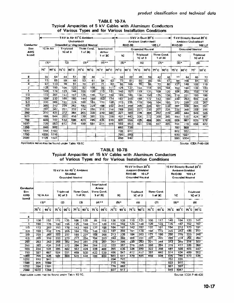
