product catalogue - shipserv€¦ · ... acoustic emission or sound • monitoring physical...
TRANSCRIPT
Condition Monitoring Product Catalogue

Introduction
World Class Innovations in Condition Monitoring
CMT is a specialised manufacturer for on-line and on-site condition monitoring solutions. Our equipment enables onsite engineers to make on the spot informed decision helping with the daily maintenance job.
CM Technologies, formerly known as Kittiwake GmbH help prevent unplanned breakdown and maximise plant availability. There are various different on-the-run tools available for condition monitoring:
• Condition monitoring for operating fluids (lubricants, fuel, water / on-site or in a lab)• Vibration Analysis, Acoustic Emission or Sound• Monitoring physical properties (speed, rpm, temperature, pressure, power ....)
Most of the condition monitoring technologies can be used as online or offline version whereas both variants do not provide the same results.
The best solution is often a combination of two or three of the condition monitoring tools, but it depends very much on the type of your condition monitoring equipment you have in use, the criticality of that equipment, the running conditions (speed, rpm, temperature ...) of your equipment, and how perceptive your organization is to training.
CMT, formerly known as Kittiwake GmbH can offer you a complete solution as on- or offline system. We are pleased to help you finding the right solution.
We want to give this catalogue to interested parties and to customers who need to get more knowledge or adjusted information for products they already use and/or want to upgrade.
The CMT-Team
Quality assured manufacturing with a focus on continuous improvement
Ever since CM Technologies GmbH was founded, formally known as Kittiwake GmbH, its paramount objective has been to manufacture and sell only high-quality products that reflect the state-of-the-art technology and meet customer requirements, with the aid of motivated employees. This self-imposed quality obligation and our experience in condition monitoring technology have enabled us to succeed in achieving a prominent market position. In line with the aspiration to continue to guarantee the highest degree of quality to our customers in future and not only to cement the reputation of our company and related market position, but to enhance it further, we introduced a quality management system in accordance with DIN EN ISO 9001 across our entire company. In addition, we would like to fulfil our customers’ requirements by maintaining a very close partnership with them, demonstrating that customers can rely on us and that we deserve their trust.
Environmental protection and sustainable development
are priority objectives of CM Technologies GmbH corporate policy. Already from the beginning, the shareholders have adopted guidelines to the environmental care. To achieve this, we have implemented an Integrated Environmental Management System that meets the requirements of ISO 14001. This policy is periodically reviewed and is monitored by measurable objectives, as part of a continual improvement process. All staff are briefed on this policy and made aware of the objectives. The policy is displayed on the company website, to demonstrate our commitment to the environment.

1
Oil Condition Monitoring
Engineered Products and Service
Water Condition Monitoring
Machinery Condition Monitoring
Training
1. Onsite Oil Test & Solutions ................................................. 4
2. Cylinder Drain Oil Management ......................................... 15
3. Independent Laboratory Oil Test ........................................ 19
4. Online Oil Sensors .............................................................. 22
1. Diesel Performance Analyzer .............................................. 28
2. Torque Meter ..................................................................... 34
3. Vibration Analysis .............................................................. 37
1. Marine Potable Water Test Kits .......................................... 48
2. Marine Sewage Water Test Kits .......................................... 53
3. Cooling and Boiler Water Test Kits ..................................... 55
1. PLC Based Central Unit ....................................................... 59
2. Control Panel ..................................................................... 60
3. CMS Options ..................................................................... 61
4. Application Specific Solutions ............................................ 63
1. Drip Type Bunker Sampler Flange ....................................... 68
2. Fuel Sampler ...................................................................... 69
3. Marpol Bunker Cabinet ...................................................... 70
4. Automatic Fuel Sampler ..................................................... 71
5. Vacuum Sampling Pump .................................................... 72
6. Sampling Bottles and Accessories ....................................... 73
1. Installation and Commission Service ................................... 77
2. Ultrasonic Cleaning Equipment ........................................... 79
3. Robot R19 .......................................................................... 81
1. Basic Oil Seminar ................................................................ 85
2. Marine Potable Water Tests ................................................ 86
3. Cylinder Drain Oil Management ......................................... 87
4. Monitoring with Vibration Analysis .................................... 88
5. Diesel Performance ............................................................ 89
Notes
Complete Monitoring Solutions
Sampling Solutions

2
Oil
Co
nd
itio
n M
on
ito
rin
g

3
Oil Condition Monitoring
1. Onsite Oil Test & Solutions ..........................4
2. Cylinder Drain Oil Management ..................15
3. Independent Laboratory Oil Test ...............19
4. Online Oil Sensors .....................................22

4
Oil
Co
nd
itio
n M
on
ito
rin
g
CMT’s oil test kit range provides on-site test equipment invaluable for any engineers responsible for high value lubricated machinery or hydraulic equipment. Economically priced these condition monitoring tools quickly will become the backbone of your maintenance regime. Engineers and maintenance managers are given the ability to conduct oil analysis directly on-site at the running machine. Spot out-of-spec fuels and lubricants before they become a critical problem by using our kits. You can choose from wide range of different set ups including complete test cabinets ensuring you get the right tool for your machinery.
CMT test kits are supplied either in durable aluminium cases or in wall mounted steel cabinets. Our multi-parameter test kits contain all of the necessary equipment and consumables for your oil condition monitoring needs.
On-site oil analysis equipment provides your chance to monitor the condition of your oil between laboratory checks. Built based on our experience in oil condition monitoring our kits are made to be used by anyone because no training or special knowledge is needed. Important oil parameters can be measured in a few minutes. Step by step instructions and on screen user guides make using the kits as simple as ever.
Your main benefits using CMT oil test devices:
• Fast and accurate results.
• Regular use of CMT´s oil condition monitoring equipment helps avoid expensive machinery failures.
• Allow you to make informed on-site maintenance decisions.
• Accurate results are available on-board or in the field without time delay.
• Allow you to act before critical failure arise.
• Robust and reliable for use in harsh environments.
• Save time and money by knowing exactly when to change the oil.
Some of our test devices need chemicals for the test routines. CMT continually invests in new developments to reduce the number of chemicals needed.
As a result of this we are currently in the position to supply most of our test kits without reagents which are hazardous for shipping. Only our AN test does require low hazardous reagents. All our water in oil test devices use non-hazardous reagents. At the same time they still work with any old style reagents offered on the market. With this backward compatibility the user enjoys a great deal of flexibility when it comes to buying refill reagents.
1. Onsite Oil Test & Solutions

5
Water is the biggest threat any oil lubricated system faces. Depending on the application water can cause serious problems for the equipment or safety. Maintain and protect your equipment by monitoring the water content.
Most parameters can be trended well by offline laboratory oil tests. This is not the case when it comes to water ingress. Water is not a by-product of the aging of oil or a result of the usage of the oil. Water ingress can come quickly and without any prior warning. Once established water levels may rise very fast. Therefore a trend analysis in a shore based laboratory does not allow a close enough monitoring of the water content to avoid problems due to a sudden water ingress.
The new developed Electronic Water in Oil TestCell does provide highest accuracy on site when testing Water in Oil giving results after a few minutes.
• Prevent corrosion, cavitation or failure of your machinery by detecting water in oil, before any damage occurs.
• Minimize instability of additive packages and damaging microbe growth by monitoring your oil.
Your benefits:
• All parts (sensor, display, battery etc) can be exchanged when needed.
• Now 30% bigger backlit display for better visibility
• Solid rugged metal housing for higher durability
• Multiple ranges for exact readings
• Multilingual software
• No hazardous reagents needed
• Undercut in the bottom to assist dosing the chemicals for all tests
Spares
The Water in Oil Reagent Pack is supplied with all needed reagents and accessories for further 50 Tests.
A Test Kit Cleaner is provided for easy cleaning after using the CMT devices. Please do not use any water based cleaning detergent.
Water in Oil
CMT Electronic Water in Oil Test Kit
Ordering Information
OTK-11201-CT
Electronic Water in Oil Test Kit
Range: 0 - 1500 ppm,
(lowest reading 100 ppm)
0 - 6000 ppm,
(lowest reading 200 ppm)
0 - 1%,
0 - 10%
Accuracy: +/- 0.01% free water
Dimensions: Ø 68 mm x 84 mm
Weight: 490 g
Test Time: 3 minutes
5 minutes in lowest range
Reagents: non hazardous
Oil
Co
nd
itio
n M
on
ito
rin
g
WIO Reagents
New
Ordering Information
Reagents & Spares
OTR-CT-12001
Water in Oil Reagent Pack (50)
OTR-CT-11000
Test Kit Cleaner (250 ml)
OTS-CT-13005
Battery for TestCell
OTS-CT-13004
Set of O-Rings for TestCell
OTS-CT-13001
Water TestCell
OTS-CT-13003
Combined TestCell (Water + BN)
Spare battery for CMT TestCell
6
Oil
Co
nd
itio
n M
on
ito
rin
g
Base Number (BN)
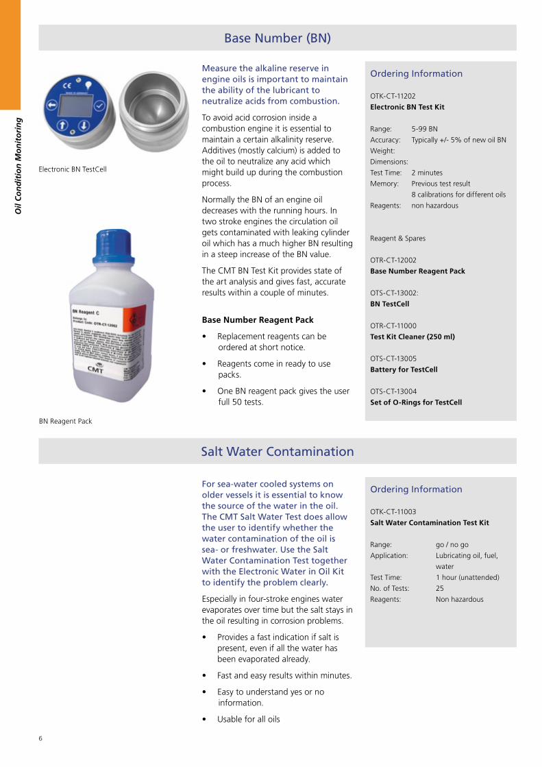
Measure the alkaline reserve in engine oils is important to maintain the ability of the lubricant to neutralize acids from combustion.
To avoid acid corrosion inside a combustion engine it is essential to maintain a certain alkalinity reserve. Additives (mostly calcium) is added to the oil to neutralize any acid which might build up during the combustion process.
Normally the BN of an engine oil decreases with the running hours. In two stroke engines the circulation oil gets contaminated with leaking cylinder oil which has a much higher BN resulting in a steep increase of the BN value.
The CMT BN Test Kit provides state of the art analysis and gives fast, accurate results within a couple of minutes.
Ordering Information
OTK-CT-11202
Electronic BN Test Kit
Range: 5-99 BN
Accuracy: Typically +/- 5% of new oil BN
Weight:
Dimensions:
Test Time: 2 minutes
Memory: Previous test result
8 calibrations for different oils
Reagents: non hazardous
Reagent & Spares
OTR-CT-12002
Base Number Reagent Pack
OTS-CT-13002:
BN TestCell
OTR-CT-11000
Test Kit Cleaner (250 ml)
OTS-CT-13005
Battery for TestCell
OTS-CT-13004
Set of O-Rings for TestCell
Electronic BN TestCell
Base Number Reagent Pack
• Replacement reagents can be ordered at short notice.
• Reagents come in ready to use packs.
• One BN reagent pack gives the user full 50 tests.
BN Reagent Pack
Salt Water Contamination
For sea-water cooled systems on older vessels it is essential to know the source of the water in the oil. The CMT Salt Water Test does allow the user to identify whether the water contamination of the oil is sea- or freshwater. Use the Salt Water Contamination Test together with the Electronic Water in Oil Kit to identify the problem clearly.
Especially in four-stroke engines water evaporates over time but the salt stays in the oil resulting in corrosion problems.
• Provides a fast indication if salt is present, even if all the water has been evaporated already.
• Fast and easy results within minutes.
• Easy to understand yes or no information.
• Usable for all oils
Ordering Information
OTK-CT-11003
Salt Water Contamination Test Kit
Range: go / no go
Application: Lubricating oil, fuel,
water
Test Time: 1 hour (unattended)
No. of Tests: 25
Reagents: Non hazardous

7
For a lubrication oil the viscosity is regarded as the oils most important characteristic. The viscosity is the resistance to flow and the strength of the oil film between moving surfaces.
• Measuring the oil viscosity provides an early detection of contamination, fuel ingress and shear thinning.
• Suitable for all mineral oils or fuels down to 1.5 cSt up to 999 cSt (heated viscometer only).
• Allows to calculate the combustion performance (CCAI) of fuel or injection / storage temperature.
The Heated Viscosity Meter can measure at 40, 50 or 80 °C and can correct to 40 or 50°C. Measuring the viscosity at 80 °C allows to measure the viscosity index. It also allows to measure very high viscosities with pin point accuracy.
The CMT Viscotube is a falling ball viscosimeter allowing to measure the viscosity of oil in centistokes on site.
The Viscotube closes the gap between the low cost viscosity stick and the highly accurate Heated Viscosity Meter.
The Viscotube is equipped with a clear screw cap at each end allowing to see the falling ball arrive at the other end. A tripod support stand on a mirror base plate helps to monitor the falling ball. The device is supplied with three sizes of balls to cover a wide range of viscosity. A digital thermometer is used to measure the temperature after completing the test.
The CMT Viscostick provides information whether the viscosity has increased or decreased. Typically it will detect 5-10% fuel dilution as well as increases in viscosity due to oil contamination like water. It can not be used to get an actual viscosity value but you will get an idea whether the viscosity is greater or smaller than the viscosity of the reference oil. It is essential that both oils have the same temperature at the time of the measurement.
Ordering Information
OTK-CT-11203
Electronic Heated Viscosity Meter
Range: 1.5-999 cSt @ 40 / 50 / 80 °C
Display: backlit LED
Keypard: Membrane type with tactile
buttons
Power: 110 to 240 AC 50/60 Hz
Weight: 3,6 kg
Dimensions: 220 x 110 x 180 (H x W x B)
Accuracy: Typically with +/- 2%
or +/- 2 cSt
Test Time: Heating from ambient tem-
perature ca. 5 minutes
about 3 minutes test time
Calculations: Calculated Carbon Aromatic-
ity Index (CCAI), Injection and
Storage Temperature,
Blending Ratio
Viscosity Index (VI) / Oil Slope
Reagents: N/A
OTK-CT-11005
Viscotube
Range: 20-600 cSt @ 40°C, using
three sizes of balls
No. of Tests: Unlimited
Test Time: 1 - 10 minutes
Reagents: N/A
OTK-CT-11004
Viscostick
Range: go / no go
Application: Lubricating oils, viscous
hydraulics
No. of Tests: Unlimited
Test Time: 1 minute
Reagents: N/A
OTR-CT-11000
Test Kit Cleaner (250 ml)
Viscosity
Viscostick
Viscotube
Electronic Heated Viscosity Meter
Oil
Co
nd
itio
n M
on
ito
rin
g

8
Acid Number (AN)
Acid Number or AN is an important oil parameter for hydraulic systems and gas engines. It is a measure of the organic and inorganic acids present within the oil.
Maintaining the acid level of an oil prevents unexpected oxidation problems. The Acid Number Test Kit does provide easy on site information of the acid number in oils.
The CMT Acid Number Test gives you instant indication of the AN increase in your lubricants.
• The test kit is supplied with all reagents needed for 25 tests.
• Simple to use drop test. Drops added will be counted until a colour change is observed.
• Titration point can be observed with the help of an advanced electronic photo cell.
• Providing you with easy to interpret results, suitable for use by untrained personnel.
Two versions are available. An economical and easy to use Acid Number Drop Test Kit. Just count the drops you need to get a colour change and get your reading from a table provided.
Alternatively we offer our Electronic Acid Number Test Kit which gives highest accuracy in the same measuring range. TAN Drop Test Kit
Ordering Information
OTK-CT-11209
Electronic Acid Number Test Kit
Range: 0-6 AN
Accuracy: +/- 0.1 AN
Test Time: 2 minutes
No. of Tests: 25
Reagents: UN2924, UN 1170
OTS-CT-13022
Spare Acide PhotoCell
OTS-CT-13005
Battery for TestCell
OTR-CT-11000
Test Kit Cleaner (250 ml)
OTK-CT-11001
Acid Number Drop Test Kit
Range: 0-6 TAN
Accuracy: +/- 0.3 TAN
Test Time: 2 minutes
No. of Tests: 25
Reagents: UN2924, UN 1170
Oil
Co
nd
itio
n M
on
ito
rin
g
Electronic Acid Number Test Kit
Ensure stability and compatibility of fuel types in minutes.
The Compatibility Tester will quickly identify potential fuel stability problems. It will also rapidly determine if a fuel is compatible with existing fuel stocks.
• Identify possible stability problems before mixing fuels, giving you peace of mind when accepting fuel deliveries.
• Prevent sludge deposits, failure of fuel handling systems and costly combustion related engine damage.
Ordering Information
OTK-CT-11207
Electronic Compatibility Tester
Range: As per ASTM D4740
Accuracy: Variation of 1 rating in
20 repeat tests
Test Time: 20 minutes (unatten-
ded)
OTK-CT-11002
Spare Test Paper
OTS-CT-13006
Compatibility Tubes
OTR-CT-11000
Test Kit Cleaner (250 ml)
Compatibility Tester
Compatibility Tester
New

9
Density Meter
Density Meter
The CMT Density Meter is suitable for both distillate and residual fuel oils. It can also be used for any lubrication or hydraulic oil if needed.
Measuring the density of fuel using hydrometers, the Density Meter can be used to confirm the quantity and grade of fuel delivered. This is especially important for ships burning heavy fuel oil since the density can vary a lot.
The Density Meter is supplied complete with four hydrometers.
• Ensure the correct amount of fuel has been delivered to your ship.
• Ensure you have been supplied with fuel and not a mixture from fuel and gas (cappuccino effect)
• Density is measured at 50°C and directly shown converted to 15°C, giving fast, accurate results. No calculation is needed.
Ordering Information
OTK-CT-11206
Electronic Density Meter
Calculations: Density at 15 °C in
vacuo, CCAI, cP/cSt
Range: 800 to 1010 kg/m3
Accuracy: Typically with +/-0.1%
Test Time: Heating from 15°C: 10
minutes
Repeat Test: maximum 30 seconds
Cleaning: 1 minute
OTS-CT-13014:
Hydrometer 820 - 880 kg/m3
OTS-CT-13015:
Hydrometer 880 - 940 kg/m3
OTS-CT-13016:
Hydrometer 940 - 1000 kg/m3
OTS-CT-13013:
Hydrometer 1000 - 1060 kg/m3
OTR-CT-11000
Test Kit Cleaner (250 ml)
Flash Point Tester
Ordering Information
OTK-CT-11204
Electronic Flash Point Tester
Temp Range: Ambient temperature
+5 to 300 °C
Sample Size: 2-4 ml
Test Time: OK in 2 minutes
Temp Running: 2° C/min.
Test Method: Closed Cup
Resolution: 0.5°C
Accuracy: 0.5°C
Flash Detection: Automatic
Voltage: 110-250 V
Frequency: 50/60 Hz
Power: 200 W
Weight: 4,3 kg
Note: A standard butane (lighter) refill
cartridge is required for operation.
OTR-CT-11000
Test Kit Cleaner (250 ml)
The CMT Flash Point Tester is an automated closed cup instrument using just a 2 ml sample size.
Increased flash point in engine oils to about 200 °C is an early indication for fuel dilution which can result in crankcase explosion.
The flammability of a material also determines its safety classification and the regulations under which it must be handled, stored and transported.
The Electronic Flash Point Tester is a compact, bench top / portable, Closed Cup Flash Point Tester designed to carry out ‘flash / no flash’ tests or to determine flash point values up to 300°C using either Ramp or Rapid Equilibrium methods.
The operating principle is that a cup containing the sample to be tested is electrically heated in a ramp function to automatically increment the temperature for repeated tests until a flash is observed, or the end of the search range
is reached, allowing rapid determination of samples.
The device also features a user-friendly yes/no test. It is heated to a user set test temperature. At the set temperature, a shutter in the lid is opened and a test flame is dipped into the vapour space above the sample. It can be determined if a sample has a flash point above or below the test temperature by detecting whether a flash has occurred or not.
Oil
Co
nd
itio
n M
on
ito
rin
g

10
Oil
Co
nd
itio
n M
on
ito
rin
g
Ordering Information
OTK-CT-11205
Electronic Insoluble Test Meter
Range: 0-2.4 Vol%
Accuracy: Typically +/-0.1%
Test Time: < 2 minutes
No. of Tests: 50 Tests
Reagents: non hazardous
Reagent Pack: OTR-CT-12003
OTS-CT-13021
Spare Insoluble PhotoCell
OTS-CT-13005
Battery for TestCell
OTR-CT-11000
Test Kit Cleaner (250 ml)
The CMT Electronic Insoluble Test Meter is a self-contained device to test insolubles and soot in your engine oil.
It is suitable for all combustion engine oils regardless of the fule in use.
It contains the latest technology to provide excellent repeatability and rapid results in the field.
Visible light is used to test the oil for soot and insolubles.
Just add one drop our of your well mixed oil sample into 10 ml reagent and present the sample tube to the device. The measuring range is detected automatically and the result is presented in seconds.
Insolubles
Insolubles Test Kit
Ordering Information
OTK-CT-11002
Insoluble Spot Test Kit
Range: good / poor
Test Time: one hour (unattended)
Reagent: non hazardous
The CMT Insolubles Spot Test Kit is a simple spot test on a specially developed filter paper to get an indication of both, the insoluble load and the dispersency or your lubricant.
Insolubles are a build up in combustion engines due to the burning fuel in the engine. They are combustion related debris and oxidation products within the lubrication oil.
Regular monitoring of insolubles helps to prevent lacquer formation on hot surfaces, sticking of piston rings, wear of cylinder liner and bearing surfaces.
The detergent property of the oil will also decrease, speeding further deterioration.
• Detect insolubles from diesel engine combustion such as partially oxidized fuel, carbon, fuel ash, oil oxidation products and used lubricant additives.
• Simple and quick to use even for untrained people.
• The insolubles tests give you actionable results, helping to maintain your engine.
Especially in trunk piston engines it is important to monitore the amount of related dabis in the lubricant. In cross head engines the level is typically much lower then in trunk piston engines but needs to be monitored as well.
Electronic Insolubles Test Kit
New

11
Ordering Information
OTR-CT-11000
Test Kit Cleaner
Size 250 ml
Reagent: non hazardous
Test Kit Cleaner
CMT provides a Test Kit Cleaner for cleaning and maintaining the individual test devices.
We recommend using the CMT Test Kit Cleaner and a soft lint free cloth for cleaning all CMT test devices.
It can certainly be used for other cleaning purposes if required.
Fuel Bacteria Test New
Ordering Information
OTK-CT-11006
Fuel Filter Bacteria Test (Dip Slides)
Range: low / moderate / heavy
Test Time: 24 - 48 h at 27 - 30°C
1-4 days at ambient
No. of Tests: 10 Tests
Reagents: non hazardous
Reagent Pack: OTR-CT-11006
OTS-CT-11007
Diesel Fuel Bacteria Test
Range: low / moderate / heavy
Test Time: 1 - 4 days at 22 - 28°C
No. of Tests: 10 Tests
Reagents: non hazardous
Reagent Pack: OTR-CT-11007
Bacteria, moulds and yeasts can all grow rapidly in fuel tanks! Free water, warmth and condensation in the fuel form the basis for growth of the Diesel Bugs.
The addition of environmentally friendly biodiesel to the fossil diesel offers microbes an excellent source of nutrition. Microbes grow more than ever and form increased amounts of “biomass”. This leads to clogged filters, corrosion and to engine failure.
Standard grades of diesel are clear and usually light yellow. The smallest discoloration can be a sign of the Diesel Bug. To be sure, you have to test it!
The CMT Diesel Fuel Bacteria Tests can be used to test the Diesel Fuel directly. The Dip Slide Test is used in case of a clogged filter. A thin film of the residues from the clogged filter can be incubated on the dip slide to evaluate if the filters clogging because of bugs or other dirt:
The Fuel Bacteria test:
• provides evaluation of Diesel Bug count (bacteria, yeast and moulds altogether).
• is easy to use.
• provides precise and reliable result.
• allows fast and safe handling.
• is suitable for all qualities of diesel fuel inclusive biodiesel.
Application: Put on the disposable gloves and take a fuel sample from the tank. Using the pipette provided measure a sample into the test bottle. Close the bottle. Tap the mikrocount® fuel bottle a few times against the hand, so that the gel breaks up. Now shake the bottle vigorously for 30 seconds until the fuel sample has mixed completely with the gel. Afterwards tap the bottle against your hand to make a flat layer of gel on the flat bottle side. Lay the bottle flat with the gel layer down in a warm (22-28 °C), dark location. After 1-4 days a positive result will be obvious and can be evaluated with the help of the charts provided.
A detailed instruction manual is provided with the test kit. Please follow the instruction carefully. Always take appropriate safety precautions when handling any type of fuel!
mikrocount® fuel – a test method for detection of contaminated diesel fuels.
Evaluation of the results:
No more than 2 spots = low contamination
Our recommendation: prophylactic dose of grotamar® 82 (25 ml per 100 l diesel)
3-25 spots = moderate contamination
Our recommendation: moderate dose of grotamar® 82 (50 ml per 100 l diesel)
More than 25 spots = heavy contamination
Our recommendation: tank inspection and if necessary tank cleaning, then shock dose of grotamar® 82 (100 ml per 100 l diesel)
mikrocount® combiKeimindikatorenAgar dip slides
Oil
Co
nd
itio
n M
on
ito
rin
g

12
Multi Parameter Combinations - Test Kits
Digital / Manual Test Kits
Product name Part number Combination
Viscotube Water in Oil Cell
Combined Water in Oil/
BN Cell
Salt Test Insolubles AN Test Viscostick
WaVis Oil Test Kit OTC-CT-20001 ■ ■
Basic Oil Test Kit OTC-CT-20002 ■ ■ ■ ■
Engine Oil Test Kit OTC-CT-20003 ■ ■ ■
Field Oil Test Kit OTC-CT-20004 ■ ■ ■ ■
Engine Oil Test Kit II
OTC-CT-20005 ■ ■ ■ ■
Marine Oil Test Kit OTC-CT-20006 ■ ■ ■ ■
Hydraulic Oil Test Kit
OTC-CT-20007 ■ ■ ■
Water in Oil Cell Density Hydrometer Low Range Falling Ball Viscometer
Free Fatty Acid Test/ AN Test
Visual Test (Cleanliness)
Diesel Oil Test Kit OTC-CT-20008 ■ ■ ■ ■ ■
Oil
Co
nd
itio
n M
on
ito
rin
g

13
Fuel and Lube Test Cabinet Configurations
Part Number
Electronic Water & BN Cell
Heated Viscosity Meter
Density Meter
Disper-sency
Spot Test
Electronic Insolubles
Test
Compa-tibility Meter
SaltTest
PourPoint
ElectronicAN Test
Flash Point
Closed
Marine Fuel & Lube Test
Cabinet
OTC-CT-30010
■ ■ ■ ■ ■ ■ (Option) (Option)
Diesel Engine Power Plant
Cabinet
OTC-CT-30011
■ ■ ■ ■ ■ ■ ■ ■ (Option) (Option)
Gas Engine Power Plant
Cabinet
OTC-CT-30012
■ ■ ■ ■ ■ (Option)
Electronic Oil Test Center
OTC-CT-30013
■ ■ ■ ■ ■ (Option)
Electronic Oil Test Center to test Insolubles, Viscosity, Acid Number, Water in Oil and Base Number
Oil Test Cabinet
Electronic Multi Parameter Combinations
Oil
Co
nd
itio
n M
on
ito
rin
g

14
Oil
Co
nd
itio
n M
on
ito
rin
g

15
Overview
Cylinder oil in a main engine has two main tasks. It should lubricate the engine to have an acceptable low wear level and it has to neutralize the sulphuric acid to avoid unexpected acid corrosion in the liner.
By analysing scrape down oil collected from the scavenge space shipboard personnel are able to monitor the condition of the engine’s cylinders and detect changes as they occur.
Scrape down oil analysis provides comprehensive laboratory testing and analysis of the oil samples. It offers on-board testing tools that enable ships’ engineers to quickly detect damages due to substantive changes of cylinder oil feed rates.
The CMT Cylinder Drain Oil Service does consist of two important major components:
• Frequent on board oil tests of BN (base number) and wear metal. The wear metal can either be tested with the an on-site manual device or with our automatic Liner Monitor system.
• Periodical onshore independent laboratory oil tests providing a complete result about wear, contamination, oil condition and additives together in a diagnostic statement from our tribology experts.
On board testing with the on-site CMT Liner Monitor and the CMT BN Test Kit provides quick results of the oil’s most important properties relative to the engine’s cylinder operating condition. The independent laboratory oil test does provide a complete result about wear, contamination, oil condition and additive components combined with a detailed diagnostic statement from a tribology engineer.
0%
10%
20%
30%
40%
50%
60%
70%
80%
Piston Rings Manpower Pistons Cylinder Liners Cylinder Oil
Rapid Return of Investment
This chart shows that the cost of cylinder oil and the liner itself are the biggest cost factors when operating a main engine. Existing installations have proved that significant cost savings can be achieved with return on investment achieved in less than a year in some cases. .
Feed Rate Optimization
Optimization means reducing to the minimum level which still ensures good lubrication and at the same time sufficient neutralisation of combustion related acids. Minimum level also means having enough for cleaning the piston surface. Even current standard electronic lubrication systems are based only on experience and standard inputs as rpm or sulphur level in the fuel. Currently there is no system available which considers a feed back about the current situation in the liner. As one of the engine’s largest overheads, an average container ship can spend $8 million and more on cylinder lubrication in its life time. Dependent upon trade, load, running hours and other factors, constant real-time monitoring is a vital tool in optimising cylinder lube oil feed rate and, as a result, improving efficiency, decreasing lubricant costs and avoiding issues related with over and under lubrication.
Engines are regularly over lubricated in an attempt to avoid problems including scuffing, but this practice not only causes high lubrication costs, it can sometimes lead to associated problems such as bore polishing. Therefore, although optimising cylinder lubricant usage is one method of achieving commercial advantage, there is a point where savings can be eroded by increased maintenance costs.
Cylinder Drain Oil
Service
Onboard Oil Test
Wear Debris Test
Analex Alert / LinerSCAN
TBN – Test
DIGI TBN Kit
Laboratory Oil Test
CMT Evaluation(optional service)
CMT
2 Cylinder Drain Oil Mangement
Oil
Co
nd
itio
n M
on
ito
rin
g

16
Oil
Co
nd
itio
n M
on
ito
rin
g
Recommended Sampling and Testing Frequency
CMT does have a lot of experience with oil testing and analysis for marine diesel engines. Based on that, we will give you some recommendation for the sampling and testing frequency. Unless advised differently by your superintendent or the engine manufacturer we recommend the following sampling and testing frequencies.
Onboard Oil Test: a) Online Liner Monitor: The Liner Monitor system is a fully automated system which does not require human interference. It takes a measurement automatically as soon as enough oil has been sampled.
b) On-site manual devices: Minimum frequency once per week. To get a much closer picture CMT recommends doing an onboard test for wear metal once per day if possible. This is essential while adjustments to the feed rate are being done. If your sampling frequency is once per week an additional sample should be taken after each fuel change to get an early indication about cat fines. This is most important for any change between low and high sulphur fuel.
c) CMT BN Test: This can be done with a much lower frequency. We recommend doing it once per week and after each fuel change to reduce the risk of acid corrosion.
Laboratory oil test: We recommend a quarterly test (or every 1000 - 1500 running hours) under normal running conditions. If there are unusual results in the laboratory report we might recommend a repeat test after a shorter period. It is advisable to follow the recommendation.
An additional test is recommended immediately when you notice any abnormality from the on board test.
BN TestCell
On board oil tests are designed to measure only single parameters. Use them as a supplement to the Laboratory Oil Test - not as a substitute. A comprehensive laboratory oil analysis is essential as part of an effective engine monitoring.

17
Laboratory Oil Service
Lab Report
The CMT Service includes:
• 100 ml sample-bottle (prepaid)
• Addressed envelope to return the sample bottle to our lab
• Sample Information Form with barcode label
• Laboratory tests: All samples are analysed and diagnosed by the end of the next business day. (As long as the samples arrive at our laboratory before noon, in our prepaid sample bottle with a correctly filled out sample information form).
• Laboratory report complete with a highly detailed diagnostic statement (prepared by a mechanical engineer)
• Dispatch of the laboratory report via mail, email, fax or data-file
• Online-recall of all laboratory reports and analysis data
You will get a detailed lab report completed with a very detailed diagnostic statement prepared by a mechanical engineer. It will be a one page report per sample with a simple rating system which quickly alerts you to problems with your oil or equipment.
There is no need for you to work through a long report of several pages. The report contains a historical look at the last 4 samples with the complete history available from our web server (including trend graphs). If you have any questions relating to your report or equipment you can call one of our service engineers to discuss your results and provide advice. The lab report will be sent to you by mail, email or fax as agreed with you.
It is possible to get the current lab reports even faster and to have, at the same time, a comparison with earlier analysed samples.
If you require your results sooner, instead of waiting for an e-mail, fax or mail you can directly log on to our fire wall protected web server. Where, as soon as we have evaluated your sample, we inform you by e-mail that the results are available. You can see the analysis results in the original version of the lab report and print it or forward it to interested parties. This service offers you to:
• Easily check online data entry for new samples
• Quickly view of all your samples
• Check sample status
You can also find your lab report on the Internet:
Test Lab Report
• Display all lab reports
• Translate lab reports into different languages
• Forward lab reports via e-mail
• Graphically view trend analysis values for individual samples
• Display of the IR spectrum and other diagrams
• View photos of the sample and the inside of the cap / lid
• View photos of the spot test, solid contaminants and much more
Quelle: Oelcheck GmbH
Quelle: Oelcheck GmbH
Oil
Co
nd
itio
n M
on
ito
rin
g
18
Oil
Co
nd
itio
n M
on
ito
rin
g
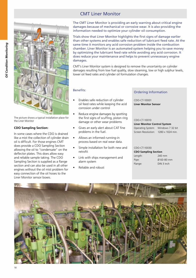
The CMT Liner Monitor is providing an early warning about critical engine damages because of mechanical or corrosive wear. It is also providing the information needed to optimize your cylinder oil consumption.
Trials show that Liner Monitor highlights the first signs of damage earlier than other systems and enables safe reduction of lubricant feed rate. At the same time it monitors any acid corrosion problem inside the combustion chamber. Liner Monitor is an automated system helping you to save money by optimizing the lubricant feed rate while avoiding any acid corrosion. It does reduce your maintenance and helps to prevent unnecessary engine damages.
CMT’s Liner Monitor system is designed to remove the uncertainty on cylinder damages resulting from low fuel quality, slow steaming, low or high sulphur levels, lower oil feed rates and cylinder oil formulation changes.
The picture shows a typical installation place for the Liner Monitor
CMT Liner Monitor
Ordering Information
CDO-CT-10001
Liner Monitor Sensor
CDO-CT-10010
Liner Monitor Control System
Operating System: Windows 7 32 bit
Screen Resolution: 1280 x 1024 min.
CDO-CT-10030
CDO Sampling Section
Length: 240 mm
Pipe: Ø 60-80 mm
Flange: DIN 3 inch
CDO Sampling Section:
In some cases where the CDO is drained like a mist the collection of cylinder drain oil is difficult. For those engines CMT does provide a CDO Sampling Section allowing the oil to “condensate” on the deflector plates. This does allow easy and reliable sample taking. The CDO Sampling Section is supplied as a flange section and can also be used in all other engines without the oil mist problem for easy connection of the oil hoses to the Liner Monitor sensor boxes.
Benefits:
• Enables safe reduction of cylinder oil feed rates while keeping the acid corrosion under control
• Reduce engine damages by spotting the first signs of scuffing, piston ring damage or other wear problems
• Gives an early alert about CAT fine problems in the fuel.
• Allows an informed running-in process based on real wear data.
• Simple installation for both new and retrofit
• Link with ships management and alarm system
• Reliable and robust

19
3. Independent Laboratory Oil Test
The oil itself is an excellent data medium which is full of valuable information if tested correctly and the findings actioned. This information highlights the condition of the oil and the machine, enabling you to identify the optimal moment for an oil change. Wear particles can be directly related or assigned to a damaged part of a given machine giving information of the condition of the plant and providing early warnings in the fight to reduce and prevent damage.
The CMT Marine Oil Test Service is a comprehensive insight into the functioning of your engine. It covers analysis of the combustion process, cylinder oil feed rates, fuel problems and identification of potential issues such as piston and liner wear, incomplete combustion and crankcase system oil analysis. In particular, we work very hard to minimize your costs related to oil consumption and feed rate. It is not in the interest of CMT to let you spend more on lubrication than necessary.
CMT has formed a strategic partnership with a certified and accredited laboratory with over 15 years experience in used oil lab analysis. A database of more than one million used oil samples from more than fifteen thousand customers all over the world and our cooperation with lube oil suppliers and engine manufacturers allows us to give you appropriate independent recommendations based on the oil analysis.
Typical applications for our independent marine oil lab service on board ships are:
Diesel Engine System Oil, Cylinder Drain Oil, Stern Tube Oil, Hydraulic Oil, Gear Box Oil and other Lubricants
The CMT service includes:
• 100 ml sample-bottle (prepaid)
• Addressed envelope to return the sample bottle to our lab
• Sample Information Form with barcode label
• Laboratory tests: All samples are analysed and diagnosed by the end of the next business day. (As long as the samples arrive at our laboratory before noon, in our prepaid sample bottle with a correctly filled out sample information form).
• Laboratory report complete with a highly detailed diagnostic statement (prepared by a mechanical engineer)
• Dispatch of the laboratory report via mail, email, fax or data-file
• Online-recall of all laboratory reports and analysis data
• Easily check online data entry for new samples
• Quickly view of all your samples
• Check sample status
• Display all lab reports
• Translate lab reports into different languages
• Forward lab reports via e-mail
• Graphically view trend analysis values for individual samples
• Display of the IR spectrum and other diagrams
• View photos of the sample and the inside of the cap / lid
• View photos of the spot test, solid contaminants and much more
Scope of analysis: (can vary with oil type)
Wear metals: Iron, Chrome, Tin, Aluminium, Nickel, Copper, Lead, Molybdenum, PQ-Index
Contaminants: Cat Fines (Aluminium / Silicon), Potassium, Sodium, Soot, Glycol, Fuel, Water %
Oil condition: Viscosity @ 40° and 100°C including Viscosity-Index, Base Number (BN) Oxidation, Nitration, Sulfation, Sludge carrying properties
Additives: Calcium, Magnesium, Zinc, Phosphor, Barium, Boron, Sulphur and Molybdenum
Ordering Information
LAB-CT-17599
Independent Laboratory Oil Analysis
Lubrication Oil Test Service
Oil
Co
nd
itio
n M
on
ito
rin
g

20
Oil
Co
nd
itio
n M
on
ito
rin
g
Internet: It is possible to get the current lab reports even faster and to have, at the same time, a comparison with earlier analysed samples.
If you require your results sooner, instead of waiting for an e-mail, fax or mail you can directly log on to our fire wall-protected web server. Where, as soon as we have evaluated your sample, we inform you by e-mail that the results are available. You can see the analysis results in the original version of the lab report and print it or forward it to interested parties.
Test methods Result Unit Test prescription
Optical Emission Spectroscopy accord-
ing (OES) ICP/RDE
Wear-, contamination- and additive elements mg/kg = ppm DIN 51396-3 ASTM-D 6595
PQ-Index Index for ferrous magnetic particles Index OPV-9-16
FT-Infrared-Spectroscopy Contamination: Water, Soot, variation to the
fresh oil reference
H2O and Soot in % JOAP and reference meth-
ods
FT-Infrared-Spectroscopy Oil Condition: Oxidation, Nitration, Sulfation A/cm DIN 51451 DIN 51452
Viscosity Viscosity at 40°C and 100°C mm2/s DIN 51562
Viscosity Index (VI) VI for the viscosity/temperature behaviour Index DIN ISO 2909
Visual Inspection Sample picture None OPV 9-12
Sludge Carrying Properties Ability of dispersants % (of remaining reserve) OPV-9-30
Gas Chromotography (GC) for the
detection of low boiling compounds
Fuel (MFO) % OPV 9-32
Water by KF Content of water ppm DIN ISO 12937
Base Number (BN) Alkalinity reserve (compared to the fresh oil) mgKOH/g ISO 3771
Particle Counting Cleanliness Code Number of particle ISO 4406
Note: Many other tests can be done as needed. The above are typical test methods for engine oils. Hydraulic oil, gear oils and some others may require additional testing, which will be carried out as required
The Independent Marine Oil Laboratory Test Service works with the following test methods for standard engine oils.
Quelle: Oel Check GmbH

21
Marine Fuel Test Service
CMT is committed to offering timely, cost-effective, quality fuel testing services to meet the needs of our global clients. We have both the competence and infrastructure to assist ship operators with total fuel management solutions, delivering measurable improvements to risk management, cost and operational efficiency, and compliance with regulatory requirements.
Safeguarding the vessel’s engine from damage caused by poor quality bunkers. We provide comprehensive technical advisory services on fuel quality and proper management of borderline and ‘off specification’ fuels. Upon arrival at our folly certified laboratory, fuel analysis is performed according to the client’s fuel purchasing specification, usually to ISO 8217:2005 or ISO-8217:2010 requirements. The full batch of tests is normally completed within 24 hours.
MARINE RESIDUAL FUELS ( Standard ISO 8217 - 2010)
Nr. Parameters Unit Method
1 Viscosity at 80 ° C cSt ISO 3140
2 Viscosity at 50 ° C cSt ISO 3140
3 Density at 15 ° C kg/l IP 160 / ISO 3675 or ISO 12185
4 Water % v/v IP 74 ISO 3733
5 Ash % m/m IP4 (Mod) ISO 6245 (Mod.)
6 MCR % m/m ASTM D4530 / ISO 10370
7 Sulphur % m/m IP 336(Mod) ISO 8754 (Mod)
8 Pour point C IP 15 (Mod) ISO 3016 (Mod.)
9 Nett specific energy Mj/kg ISO 8217 (by calculation, Annex A)
10 CCAI ISO 8217 (by calculation, Annex A)
11 Flash point C IP 34(Mod), ISO 22719 (Mod)
12 Total Sediment Potential (TSP) % m/m IP 390B / ISO 10307 - 2
Elements
13 Silicon (Si) mg/kg IP 501/ IP 470 / ISO 10478
14 Aluminum (Al) mg/kg IP 501/ IP 470 / ISO 10478
15 Vanadium (V) mg/kg IP 501/ IP 470 / ISO 10478
16 Zink (Zn) mg/kg IP 501 / IP 470
17 Phosphorus (P) mg/kg IP 501 / IP 470
18 Calcium (Ca) mg/kg IP 501 / IP 470
19 Sodium (Na) mg/kg IP 501/ IP 470
20 Al& Si mg/kg IP 501/ IP 470 / ISO 10478
21 Injection temperatures calc.
22 Acid Number mgKOH/g IP 276-95
DISTILLATE MARINE FUELS ( Standard ISO 8217 - 2010)
Nr. Parameters Unit Method
1 Cetane lndex IP 364 / ASTMD 976
2 Water % v/v IP 74 / ISO 3733
3 Ash % m/m IP 4/ ASTM D524
4 MCR % m/m ASTMD 4530 / ISO 10370
5 Sulphur % m/m IP 336(Mod) ISO 8754(Mod)
6 Pour point C IP 15(Mod) ISO 3016 (Mod)
7 Flash point C IP 34(Mod) ISO 2719 (Mod)
8 Total Existing Sediment (TSE) % m/m IP 375 / ISO 10307 - 1
9 Visual Inhouse Standard
10 Acid Number, TAN mgKOH/g IP 276-95
11 Viscosity at 40 ° C or 100 ° C cSt IP 71 / ISO 3104
12 Density at 15 ° C kg/l IP 160 /ISO 3675 or 12185
Ordering Information
LAB-CT-17600
Independent Fuel Oil Analysis
Laboratory Test
Quelle: Oel Check GmbH
Quelle: Oel Check GmbH
Oil
Co
nd
itio
n M
on
ito
rin
g
New

22
4. Online Oil Sensors
Water Monitor
While maintenance costs increase and production capacity and equipment performance is optimized the demand for on-line machinery and oil condition monitoring is increasing permanently. CMT had designed a range of instruments to accomplish the primary objectives of oil analysis.
New technologies deliver new ways to protect your investments. Using our oil sensors to monitor the condition of the oil can now be applied as the technology is available and has proven its worth in the field.
Now more than ever it is necessary to get the most out of the machinery, to minimize downtimes, streamline maintenance and to avoid unnecessary costs.
Online oil sensors are a great addition to your offline oil analysis program giving you an early alert about critical situations. They also might allow to extend the sampling intervals but do give at the same time an indication when an additional oil sample should be sent to a laboratory for more detailed information and double check of the problem.
The effect of water ingress into an oil system can be rapid and catastrophic. The Water Monitor removes the risks associated with periodic off-line testing and potential human error. In comparison to other techniques for water monitoring, CMT´s Water Monitor measures the total concentration of water in oil, not just the dissolved water. CMT´s Water Monitor already has been installed on a multitude of seafaring vessels, where it proves its worth every single day!
A robust design with an IP65 housing ensure that CMT´s Water Monitor can provide permanent, repeatable accurate and reliable real time data in harsh marine and industrial environments.
Continuous on-line monitoring provides the most representative picture of oil condition. Changes are highlighted as they occur and not just at scheduled laboratory analysis. Preventative action can then be taken before a significant damage can occur.
Water Monitor provides accurate feedback of the water concentration in your oil system. With local and optional remote alarms, Water Monitor instantly puts the information enabling the engineers to act accordingly.
Ordering Information
SEN-CT-16901
CMT Water Monitor
Specific Oil
Calibration
Generic Oil
Calibration
Accuracy +/- 2% +/- 5%
Resolution 100 ppm 200 ppm
Specifications
Ambient Temperature: +5°C to +55°C
Oil Pressure Range: 2 to 10 bar
Maximum Oil Temperature: < 60 °C (at oil inlet)
Power: 110 / 230V AC 50/60 Hz
Analogue Outputs: 2 x 4 - 20mA
Connectivity: USB, CANOpen, TCP/IP and 4-20 mA
Oil
Co
nd
itio
n M
on
ito
rin
g

23
Combined Oil Condition and Moisture Sensor
The Combined Oil Condition and Moisture Sensor goes beyond the normal protection systems.
It is a permanent sensor for the continuous determination of the oil condition, humidity and temperature in hydraulic and lubricating oils. It permanently monitors dissolved water, temperature and oil quality at the same time. It puts you in control of your lubricant. Prompt informations are given on changes in the fluid allowing immediate actions in case of deteriorating operating conditions.
Monitoring of changes in hydraulic fluids and lubricants are essential for condition based maintenance. Data is continuously documented evaluated and stored. In that way deterioration and changes in the oil (e.g. water leakage, oil change, ...) can be indicated.
Through this, damage can be recognized or completely avoided at an early stage. This offers the opportunity to prevent machine failures as well as to prolong maintenance and oil change intervals by means of appropriate measures. Furthermore, by monitoring the lubricant, correctly performed maintenance work and the use of the required lubricant quality may be documented.
Supplied with a standard ¾“ thread it can easily be integrated in a return line or the tank. The communication with the sensor is either done over a serial RS232 interface, over analog outputs (4...20 mA) or CANopen interface. In order to enable a long-term record of data, the sensor is equipped with internal data storage unit which can be read out over the serial interface.
The sensor records the change in temperature, relative oil humidity and water activity, relative permittivity and conductivity of the fluid. As all readings do show a strong connection to the temperature, next to the characteristic values at current temperature the sensor also sends the data at reference temperature. The sensor is able to evaluate condition changes automatically. Alerts can be sent to the CAN interface if needed.
Ordering Information
SEN-CT-16903
Combined Oil Condition and Moisture
Sensor
Stainless steel housing - rugged and long life performance
Smart sensor with internal processing power offers wide range of interface options
Widely used 3/4” DIN thread - quick and easy installation to a wide range of machin-ery
High pressure resistant hermetic seal for fluid pressure up to 50 bar.
Switching output signals for oil condition value, relative humidity and temperature,
Oil
Co
nd
itio
n M
on
ito
rin
g

24
Oil
Co
nd
itio
n M
on
ito
rin
g
By using the sensor different changes of the oil condition can be detected. Providing a % relative humidity, condition of the oil and temperature values. Now you can monitor main parameters real-time. The sensor can be mounted within any lubrication system on any type of machine. The sensor measures the oils percentage Relative Humidity, resulting from the dissolved water within the lubricant, using a combination of proven thin film capacitance sensors, combined with smart algorithms to provide a temperature, oil condition and % RH value.
Whether it’s to check on the health of the machine, or an alert of changing moisture ingression rates, the new developed combined sensor provides instant information, complementing your existing laboratory oil analysis programme, and helping you make informed maintenance planning decisions.
Specifications
Moisture: 0 - 100 % saturation (+/- 3%) relative humidity
Temperature: -25 - +100 °C (+/- 3%)
Oil Condition Value +/- 30 % of initial value
Resolution: 0.1% relative humidity
Analogue Outputs: 3 x 4-20mA for % Saturation, temperature and oil condition of oil
Switch Output: 3 x Alarm adjustable
Thread Connection G 3/4 DIN 3852 E (torque value 30 Nm)
Fluid Compatibility: Mineral oils, HLP ester based fluids, Polyalphaolefine
Material: 304 Stainless Steal
Max Oil Pressure: 50 bar
Pressure resistance max. 500 bar
Flow velocity max. 5 m/s
Oil Temperature Range: -25 to 100 °C
Power Supply: 10 - 36 V (DC) < 0.2 A
Sealing on enclosure: IP67
UBPNP switch output
GND
4 ... 20 mA outputNot in use
To allow an easy installation into a standard G 1/2 inch line CMT does provide an optional mechanical housing for the sensor.

25
Metallic Particle Sensor
The Metallic Particle Sensor is an intelligent sensor that detects electrically conductive particles in the medium that passes through it. The sensor counts them in real-time and classifies them according to their size.
The Metallic Particle Sensor uses a new patented detection method which is based on the eddy current principle and works independently of oil temperature, flow rate, viscosity, air and water contents or oil colour (darkening).
It can be mounted within almost any lubrication system on any type of machine. The sensor measures ferrous and nonferrous metals, resulting from the wear debris within the lubricant, using a combination of proven inductive coil technology, combined with smart algorithms to provide a particle size distribution count. And that puts you in control. You know that the more severe the wear problem, the more that the machine produces larger wear debris particulate.
With its digital and analogue outputs, it can be easily integrated into your existing Condition Monitoring and operating control systems. It puts you in control. Whether it’s to check on the health of the machine, or an alert of changing wear patterns, the sensor provides instant information, complementing your existing laboratory oil analysis programme, and helping you make informed maintenance planning decisions.
Ordering Information
SEN-CT-16904
Wear Monitor
The eddy current measuring principle
An excitation coil (black) that generates an alternating magnetic field (blue) induces eddy currents (green) in the oil. A receiver coil detects the resulting eddy current density. Electrically con-ductive, i.e. ferrous and non-ferrous contaminants in the oil change the current flow between the excitation and the receiver coils. In order to detect even miniscule particles at high flow velocities the Metallic Particle Sensor utilizes the fast reacting differential coils method with two receiver windings connected in opposition.
Specifications
Enclosure Stainless steel 1.4308 (seawater proof)
Ambient Temperature: -20 to 80°C
Interfaces / Protocols: TCP / IP, Modbus over Ethernet
Connections: 1/2 female, other sizes available on request
Particles: Ferrous and nonferrous metallic, Simultaneous quantification of metal-
lic composition, size category and particle count.
Particle size class up to 8 different size classes can be set starting from 50µm
Fluid Compatibility: Petroleum, synthetic, biodegradable oils and water/oil emulsions
Power supply: +21 - 30 V (DC)
Weight / Dimensions: 3.5 kg / 120 x 80 x 80 mm
Flow Rate: 0.01 - 5.0 m/s (0.1 - 40 l/min)
Sensor Bore: Diameter 10 mm, Length 120 mm
Max Fluid Pressure: 16 bar
Max Fluid Viscosity: 500 cST
Internal Memory: 64 MB ~ (150 days)
Signal Processing: Particle distribution counter with integral average determination and
classification

26
Oil
Co
nd
itio
n M
on
ito
rin
g
27
Machinery Condition Monitoring
Mac
hin
ery
Co
nd
itio
n M
on
ito
rin
g
1. Diesel Performance Analyser .....................28
2. Torque Meter ........................................... 34
3. Vibration Analysis Solutions ......................37
28
1. Diesel Performance Analyser
Diesel Indicator
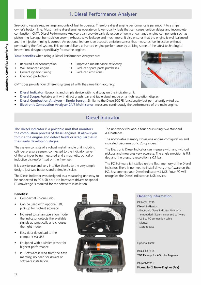
The Diesel Indicator is a portable unit that monitors the combustion process of diesel engines. It allows you to tune the engine and detect faults or irregularities in their early developing stages.
The system consists of a robust metal handle unit including cylinder pressure sensor, connected to the indicator valve of the cylinder being measured and a magnetic, optical or inductive pick-up(s) fitted on the flywheel.
It is easy-to-use and very intuitive thanks to the very simple design: just two buttons and a simple display.
The Diesel Indicator was designed as a measuring unit easy to be connected to PC USB port. No hardware drivers or special IT knowledge is required for the software installation.
The unit works for about four hours using two standard AA batteries.
The nonvolatile memory stores one engine configuration and indicated diagrams up to 20 cylinders.
The Electronic Diesel Indicator can measure with and without pickups and measures very accurate. The angle precision is 0.1 deg and the pressure resolution is 0.1 bar.
The PC Software is installed on the flash memory of the Diesel Indicator. There is no need to install drivers or software on the PC. Just connect your Diesel Indicator via USB. Your PC will recognize the Diesel Indicator as USB device.
Benefits:• Compact all-in-one unit.
• Can be used with optional TDC pick-up for highest accuracy.
• No need to set an operation mode, the indicator detects the available signals automatically and chooses the right mode.
• Easy data download to the computer via USB
• Equipped with a Kistler sensor for highest performance
• PC Software is read from the flash memory, no need for drivers or software installation.
Ordering Information
DPA-CT-17735
Diesel Indicator
– Electronic Diesel Indicator Unit with
embedded Kistler sensor and software
– USB to PC connection cable
– Manual
– Storage case
Optional Parts:
DPA-CT-17730
TDC Pick-up for 4 Stroke Engines
DPA-CT-17731
Pick-up for 2 Stroke Engines (Pair)
Mac
hin
ery
Co
nd
itio
n M
on
ito
rin
g
Your benefits when using a Diesel Performance Analyser are:
• Reduced fuel consumption• Well balanced engine• Correct ignition timing• Overload protection CMT does provide four different systems all with the same high accuracy:
• Diesel Indicator: Economic and simple device with no display on the indicator unit.• Diesel Scope: Portable unit with direct graph, bar and table visual mode on a high resolution display.• Diesel Combustion Analyser – Single Sensor: Similar to the DieselSCOPE functionality but permanently wired up.• Electronic Combustion Analyser 24/7 Multi senor: measures continuously the performance of the main engine.
Sea-going vessels require large amounts of fuel to operate. Therefore diesel engine performance is paramount to a ships owner’s bottom line. Most marine diesel engines operate on lower-quality fuels that can cause ignition delays and incomplete combustion. CMTs Diesel Performance Analysers can provide early detection of worn or damaged engine components such as piston ring leakage, burnt piston crown, exhaust valve leakage and much more. It also ensures that the engine is well balanced and the injection timing is correct. An optional feature is an acoustic emission sensor that measures fuel injection without penetrating the fuel system. This option delivers enhanced engine performance by utilizing some of the latest technological innovations designed specifically for marine engines.
• Improved maintenance efficiency• Reduced spare parts purchases• Reduced emissions

29
Mac
hin
ery
Co
nd
itio
n M
on
ito
rin
g
The DieselSCOPE is a portable unit that monitors the combustion process of diesel engines with a speed of up to 3000 rpm in real time. It allows you to tune the engine while measuring and detecting faults or irregularities early in the developing stages.
The DieselSCOPE system consists of a handheld unit, a cylinder pressure sensor connected to the indicator valve of the cylinder being measured, and an optical or inductive pick-up(s) fitted on the flywheel.
It is easy-to-use and very intuitive thanks to the single function buttons: Engine, Measure, File, Graph, Bar, Table, Mode, Setup and Help. There are no hidden sub menus. The large icons are self-explanatory. Navigate with the arrows, confirm by the Yes button, return back by No.
The DieselSCOPE was designed as a stand alone unit. The long battery life, the 320 x 240 pixels screen allows using it without a PC. The big nonvolatile memory stores 60 measurement records, up to 20 cylinders each. The engine library can keep 30 engine data files. It measures in auto-stop and continuous mode.
The DieselSCOPE has Graph, Bar and Table visual modes. All three can be used to measure or to analyse data records.
The bar view shows the Pressure - Angle diagram(s). You can compare cylinders, zoom the diagrams, read the pressure at the cursor position from multiple diagrams.
The bar view displays either absolute or relative (% deviation) plots of a selected measured or calculated parameter for cylinder-to-cylinder comparison.
Table mode shows the values of RPM, P(ind), P(cmp), P(max) and A(ign) of a selected cylinder.
The values of all other parameters of all cylinders are shown when scrolling through the table of results.
The DieselSCOPE is supplied with a PC software package called DieselSCOPE View. The transfer of measurement records and engine data files to a PC is done via USB connection.
The DieselSCOPE View software helps to analyse the combustion process, store the measurements in data files, print diagrams or complete reports, sent data files by E-mail to the office.
The DieselSCOPE View facilitates the evaluation of the engine condition. Variety of diagrams, bar plots and tables present the measurements and the manually entered data in a user-friendly way.
The DieselSCOPE View makes it easier to compare current with previously taken reference data and thus to detect worn parts or incorrect adjustment.
The DieselSCOPE helps to reduce the engine’s operating cost. Cylinder-to-cylinder load balancing and correct fuel injection settings will optimise engine performance and minimize specific fuel oil consumption.
Ordering Information
DPA-CT-17729
DieselSCOPE Standard
1. DieselSCOPE handheld unit
230x105x40mm, 500 gr, 20 hours
battery life
2. Kistler Pressure Sensor
3. Thompson Adapter
4. PC to DieselSCOPE USB Cable
5. Battery Charger
6. “DieselSCOPE View” Software Package
7. Instruction Manual
Optional Parts
DPA-CT-17730
TDC Pick-up for 4 Stroke Engines
DPA-CT-17731
Pick-up for 2 Stroke Engines (Pair)
DPA-CT-17733
Acoustic Emission Sensor
DieselSCOPE

30
Emission (AE) waves are commonly defined as transient elastic waves within a material caused by the release of localized stress energy. Hence, an event source is the phenomenon which releases elastic energy into the material, which then propagates as an elastic wave.
AE events that are commonly studied among material failure processes include the extension of a fatigue crack, or fibre breakage in a composite material.
AE is also related to an irreversible release of energy that can be generated from sources not involving material failure including friction, cavitation and impact. Acoustic emissions can be detected in frequency up to 100 MHz.
The Acoustic Emission Sensors is a piezoelectric sensor with built-in amplifier and signal conditioning. It is optimised to detects elastic waves in the range of 300 to 700 KHz , which are caused by the injection of the fuel through the nozzle, exhaust gas flow through the valve, impact of the injector needle, closing and opening of the fuel pump spill.
The AE sensor is used to measure the angle at which these events occur and to detect deviations in injection timing, late burning of fuel in the cylinder, leaking injectors.
Specifications
Frequency Range: 200-700 KHz (Acoustic Emission)
Operating Temperature: 130 °C
Power Supply: 5.00 +/- 0.25 VDC
Output Signal: 0.5-4.00 VDC
Attachment: Alnico Magnet, 5.2 kg pull force
Diameter: 26 mm
Connector: Neutrik, NC4MP-BAG
The optional Acoustic Emission (AE) Sensor can be used for the DieselSCOPE, the Combustion Analyser and the Electronic Combustion Analyser 24/7. It is not suitable for the use with the ECON Diesel Indicator.
Benefits: • No penetration of the fuel system
– eliminates possible fuel leakage
• Latest Acoustic Emission technology
• Applicable for 2-stroke and 4-stroke engines
• Extended life cycle compared to pressure sensors
Fuel after burning
Leaking nozzle
Mac
hin
ery
Co
nd
itio
n M
on
ito
rin
g
Ordering Information
FDPA-CT-17733
Acoustic Emission Sensor
Optional Fuel Sensor

31
The Viewer helps to analyse the combustion process, store the measurements in data files, print diagrams or complete reports and sent data files by E-mail to the office
The software facilitates the evaluation of the engine condition. A variety of diagrams, bar plots and tables present the measurements and the manually entered data in an user-friendly way.
The Viewer software makes it easier to compare current with previously taken reference data and thus to detect worn parts or incorrect adjustment.
The software helps to reduce the engine’s operating costs. Cylinder-to-cylinder load balancing and correct fuel injection settings will optimise engine performance and minimize specific fuel oil consumption.
View Software for Diesel Performance Analyser
Mac
hin
ery
Co
nd
itio
n M
on
ito
rin
g

32
Diesel Combustion Analyser - Single Sensor
Benefits:
• Uses existing PC to measure engine performance
• Runs under Windows 2000, XP, Vista and Linux
• USB CJB with lifetime guarantee
• Fast measurement (8 cylinders in 5 minutes)
• Real-time cylinder and fuel pressure measurements
• Small data files (31 KB for 7 cylinder engine)Coloradoan connectors• no wiring• easy installation• no grounding problems
Powered by the PC• isolated pressure measurement
channel• eliminates 220/110 voltage problems
Small metal junction boxes• easy trouble shooting• repairs by component exchange
Handheld repeater unit• one-man operation• tune engine while measuring
Ordering Information
customized system
- please contact our office to discuss details -
The Diesel Combustion Analyser has been developed to be used for one up to four engines, monitoring the cylinder pressure and fuel injection system.
Operating costs, especially labour and maintenance costs, can be minimized, engine downtimes get shortended. The intention is to optimise engine operations while saving time and investigations.
Mac
hin
ery
Co
nd
itio
n M
on
ito
rin
g

33
Electronic Combustion Analyzer 24/7 Multi Sensor
Technical Data Sensor
Measuring Range: A24 (0...200bar), A14 (0...103 bar), A34 (0...300bar)
Sensitivity: A24 (50 µA/bar), A14 (100 µA/bar), A34 (33,3 µA/bar)
Overload: 300 bar
Connector (IP67): M12x1
Linearity at 23°C: < ± 0,75 %FSO
Mounting Torque: 15 N • m
Zero Point (no pressure): 10 mA
Signal Stroke FSO 10 mA
Operating temp. range, Sensor
front:
-50...350 °C
Operating temp. at cable connect.: -20...200 °C
Operating temp. Charge amplifier: -10...85°C
Supply Voltage: 16...30 V DC
Weight: 150 g
Ordering Information
customized system
- please contact our office to discuss details -
Benefits:
• Longer lifetime of components
• Optimized maintenance planning
• Early fault detection
• Increased operational safety
• Lower fuel consumption
• Easy technical reporting
Features:
• Synchronous cylinder pressure measurement of up to 12 cylinders
• 3 x 4-20mA Inputs
• 4 x Digital Outputs
• 2 x 62 Diagrams Buffer
• p(max) alarm record
• USB data transfer to PC
The Electronic Combustion Analyser 24/7 Multi Sensor is the most advanced system for continuous diesel engine performance. It has been developed to be used for one Main Engine Only. It can monitor up to 12 cylinders and log the data permanently. The Electronic Combustion Analyser is a comprehensive system for continuous engine performance measurement and monitoring which will provide the key knowledge for obtaining optimum and reliable engine performance data. Using the combustion information you will have minimum engine wear, an optimum emission and fuel consumption.
Mac
hin
ery
Co
nd
itio
n M
on
ito
rin
g

34
2. Torque Meter
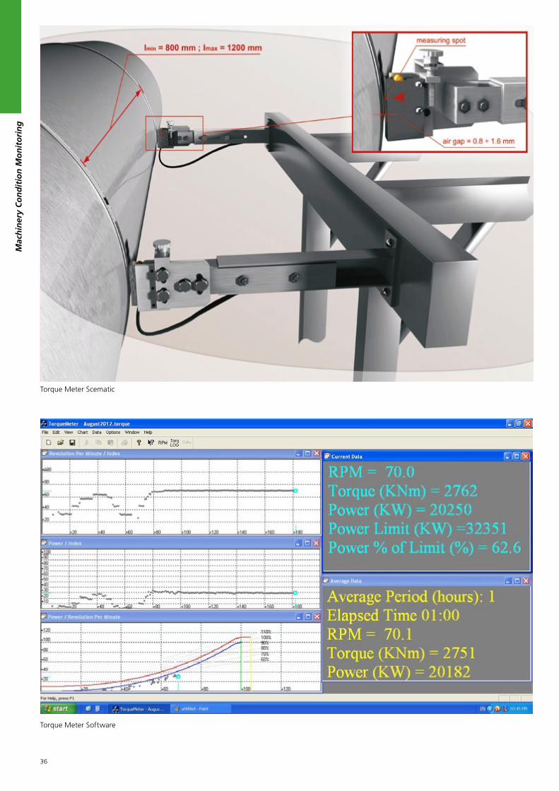
The CMT Torque Meter is a permanent monitoring system which continuously measures the shaft (effective) torque, power and RPM. The torque meter itself consists of two metal tapes with magnetic pattern, two sensors and a transmitter. It is 24 V (DC) powered, with 2 x 4-20mA current outputs, a pulse RPM output and a serial port (RS232 or USB).
A 4-20 mA signal, proportional to the shaft torque in % of the MCR value is averaged by a preset number of up to 255 consecutive revolutions. The 4-20 mA torque output and the pulse RPM signal are connected to the optional TM Junction Box ( or TM – USB box). Shaft power is calculated by torque and RPM. All data is transferred to a PC via the USB connector.
Optional the package includes a dedicated PC software that displays on a monitor the actual torque, power and RPM value. The software calculates and displays both, the current data and the moving average values of power, torque and RPM. The moving average period is set from 1 to 24 hours. The measured data is saved in a preset period of 1 to 60 minutes. The TM software displays trends of the saved data and the current and saved measurements on the main engine power / rpm diagram, as defined by the engine manufacturer.
The measured data can be exported in an Excel compatible CSV (Comma Separated Values) file for further calculations and analyses.
Advantages:
• Digital method of shaft twist measurement, not affected by changes in temperature, propeller thrust or shaft misalignment and stress;
• Contact free digital sensors;
• High precision - time resolution of 0.1 milliseconds;
• Simple & easy to install also for retrofit installations;
• No need to provide power to the components on the shaft;
• No need to transfer by telemetry any signals from rotating components;
• Simple zero calibration procedure;
• User friendly and maintenance free
Mac
hin
ery
Co
nd
itio
n M
on
ito
rin
g
Torque Meter Istallation

35
The torque meter package comprises 2 metal strips (with a magnetic pattern), two sensors and a transmitter. The tape provides 150 to 600 pulses per revolution, depending on the diameter of the shaft. The sequential magnetic north and south poles of the tape are detected by the sensors.
The microprocessor based transmitter detects the shift of pulses of the second tape (the twist of the shaft), caused by the torque and calculates the actual torque reading.
Scope of delivery:
• 2 metal strips with magnetic pattern, cut to lenght
• 2 protective stainless strips
• 2 sensors with 2 m connection cables
• 1 transmitter, with 5 m sensor connection cables
• 2 Adjustable Sensor arms
• 25 m cable
Ordering Information
CMS-CT-18319
Torque Meter
Contact- free method for permanent torque
& power measurement
• Permanent torque and power
measurement
• Shaft diameter 200-1000 mm.
Other sizes on request
• Sensor: Contact-free
• 0.1 ms resolution = 2 x 10 -6 degrees at
120 RPM
• Power supply: 24 V (DC)
• Two 4-20 mA outputs for rpm, torque or
power (set by jumper in the transmitter box)
Transmitter Output Signals
Output 1: 4 - 20 mA (Power, Torque or RPM)
Output 2: 4 - 20 mA (Power, Torque or RPM)
Output 3: passive pulse RPM output (one pulse per revolution)
Output range: 4 mA = 0 and 18 mA = MCR (Power, Torque or RPM)
RPM at MCR: 60 - 180 RPM
Time resolution 0.1 milliseconds
Output average 1 - 255 revolutions
Operating temp.: -10...85°C
Power Supply: 24 V DC
Mac
hin
ery
Co
nd
itio
n M
on
ito
rin
g
36
Mac
hin
ery
Co
nd
itio
n M
on
ito
rin
g
Torque Meter Scematic
Torque Meter Software

37
The Vibration Meter is a multi-function portable meter that bridges the gap between the basic Vibration meter and advanced FFT data collector / analyser.
It is a complete machine condition monitoring system that gives results without the use of a computer or laptop. It is designed for the technician, engineer and consultant who needs to analyse a rotating machine on-site without investing and carrying expensive instruments to site. Using the CMT Vibration Meter cannot be easier!
Both experts and users without knowledge of vibration analysis can use the device immediately. For the latter the FASIT-Mode (fault source identification tools) has been introduced for simple and rapid damage analysis. It gives an immediate analysis of the problem according to the “traffic light” principle.
3. Vibration Analysis Solutions
Bearing problems are the most common cause for machine and plant damage.
Slight misalignment or imbalance creates significant greater than expected load for a bearing. Very often bearing lubrication is found insufficient. All of these factors reduce the service life of bearings. The identification of insufficient lubrication or a source for a bearing damage is no great matter and done in a few minutes.
A detailed problem analysis is important. So it happens that engineers suspect a bearing damage, but gear problems are actually present. The bearings are replaced now, costs are incurred without eliminating the problem. Therefore it is essential to find the cause of the problem. Just changing a bearing where an imbalance or a misalignment is causing the problem does not solve the problem and the bearing will fail shortly again creating more cost.
Statistics show that insufficient bearing lubrication is the highest cause for most bearing damages. Finding lubrication problems is simple and fast with the CMT vibration and ultrasonic devices. A single measurement of only a few seconds gives information about the lubrication of the bearing. Avoid bearing damage and unnecessary costs without much effort.
Already at the first measurement simple pictograms show whether a lubrication problem, an unbalance, loose parts or a bearing damage is present.
With this unique measuring device, unskilled users can perform following more measurements:
• temperature
• speed measurement
• strobe scope
• stroboscope
In addition it incorporates a handy inspection torch.This single meter undertakes:
• overall vibration measurement
• three band spectrum
• Time Wave Form
• FFT spectrum
CMT Vibration Meter
Specification Vibration Meter
Input 1 x ICP powered accelerometer 100 mV/g
Display 128 x 128 pixel
Output 1 x AC signal for external headphones
Velocity 10 - 1000 Hz
Acceleration 500 - 16 000 Hz
Displacement 1 - 1000 Hz
Velocity Spectrum 0 - 200 Hz
Stroboscope 10 - 18000 rpm
Operating Temp. -5 - 50 °C
Dimensions 150 x 60 x 35 mm
Weight 350 g device / 540 g complete
Mac
hin
ery
Co
nd
itio
n M
on
ito
rin
g

38
Mac
hin
ery
Co
nd
itio
n M
on
ito
rin
g
Vibration Meter is a revolutionary instrument with a completely new design! The operation of the instrument is so easy that anybody can learn to use it very quickly. The instrument uses the colours green, yellow and red to display the status. Determination of individual machine or bearings defect types is done directly during operation, without a need to use a computer or software.
Instruments in this cost-effective category have been able to measure only total vibration values so far. But the Vibration Meter is different. For each point on the machine this device produces many different measurements:
• overall RMS and PEAK velocity (10 – 1.000 Hz)
• overall RMS and PEAK acceleration (500 – 16.000 Hz)
• overall RMS and PEAK displacement (1 - 200 Hz)
• velocity spectrum (0 - 200 Hz)
• acceleration time signal (bearing fault detection in 500 – 16.000 Hz band)
• acceleration enveloping measurement
• automatic machine speed detection
• non-contact temperature measurement
• displacement measurement
CMT Vibration Meter is sold as complete set with a quality accelerometer, coiled cable, magnetic base, transit case and optional headphones. You can connect headphones to this instrument and listen to vibration signals. Do not consider this method out of date! If you measure transmissions or slow-running bearings, you will quickly understand its usefulness.
Some examples of the different modes:
Unbalance, looseness and misalignment, lubrication and bearing damages
This screen is all you need for a quick diagnosis. It gives an overview by traffic light of unbalance, looseness, misalignment, lubrication condition and damages of the bearing.
RPM is automatically detected and displayed at the bottom of the screen.
This screen has been introduced especially for users with no or limited experience in vibration analysis.
RMS Vibration levels
The device measures the RMS vibration level; and compare with the severity limits of ISO10816-3. Readings changes in Traffic Light colour when an exceeding occurs.
Bearing temperature is measured by infra-red and indicated in traffic light. An overheating of the bearing can be easily identified as a RED bar as shown in the figure (left side). Temperature reading in °C and °F is shown in another screen.
RPM is automatically detected and displayed at the bottom of the screen
Bearing fault detection
Vibration Meter measures the g-ENV, which represents the condition of the bearing. Vibration Meter also display the vibration time signal. You can visualize the vibration impact due to bearing fault by looking at its time signal. It is useful in differentiating whether the increase in g-ENV is due to bearing fault or just lack of lubrication. You can also listen to the vibration signal through the audio output, which is a proven technique for bearing fault detection especially for slow rotating machine.

39
Vibration Spectrum (FFT)
Vibration Meter measures the FFT spectrum in the range of 0-200 Hz and displays the most three dominates peaks including the velocity value in mm/s. The information is useful for detection of unbalance and looseness.
Stroboscope
The build-in stroboscope inside the Vibration Meter represents the unique innovation in the handheld vibration equipment. A high intensity LED is being used.
The stroboscope is very handy for inspection of rotating or moving machinery (belt, fan, coupler…). For example, missing screw can be seen without stopping the machine - can be a big cost saving. The device can automatically detect the rotating speed of the machine and freeze the movement by setting its flashing frequency the same as the rotating parts. Frequency can also be set manually.
Ordering Information
VIB-CT-50001
CMT Vibration Meter
VIB-CT-50005
Acceleration Sensor 100 mV/g
VIB-CT-50011
Standard Measuring Pad with
Plastic Cover a 10 pcs.
VIB-CT-50018
Epoxy Metal Glue for Measuring Pads
VIB-CT-50017
PELTOR Heavy Duty Headphone
Usng Headphones
The device does allow connecting headphones to this instrument and listen to vibration signals. Do not consider this method out of date! If you measure transmissions or slow-running bearings, you will quickly understand its usefulness. With a little bit of experience this will allow you to distinguish good bearings from bad bearings. You can also hear the gear mesh in case of gearboxes. Last but not least this is an excellent method to hear if a bearing is lubricated well. If you use this while lubricating your bearing you know exactly when the bearing is well lubricated. This avoids over or under lubrication which can both be critical for your equipment.
With its excellent attenuation, the The CMT Headphones offers unique acoustic performance in very high noise environments. The proven and durable design ensures high comfort levels, allowing long term use under very tough conditions.
Mac
hin
ery
Co
nd
itio
n M
on
ito
rin
g

40
Mac
hin
ery
Co
nd
itio
n M
on
ito
rin
g
CMT Vibration Meter Pro is a professional and robust 2 channel Vibration Analyser which is a valuable tool for maintenance engineers for fault diagnosis and data collection.
Vibration Analyser contains these measurement modes:
• Velocity / Acceleration
• Time Signal
• Spectrum
• Data Collector (Route measurements)
• FASIT – Fault Source Identification Tool
Key features:
• FASIT - Fault Source Identification Tools
• FFT spectrum with 25,600 lines
• 2 AC + tacho + 2 DC channels (temp. pressure..)
• Stroboscope / Torch
• IR Temperature Sensor
• USB connection for data transfer
• Colour display 320 x 240
Measurement of 2 channels simultaneously gives a lot of flexibility in fault diagnosis. For instance, you can get a good insight of the alignment by measuring the radial and axial vibration across the coupling of the motor and pump.
8 GB allows continuous recording of 2 channel raw signals up to 25.6 kHz. Even under pressure, you don’t have to worry that important data could be missed.
CMT Vibration Meter Pro
FASIT - Fault Source Identification Tools
FASIT allows immediate assessment of the overall vibration severity according to ISO10816-3 and identification of the following faults using colour scale:
• bearing fault
• unbalance
• misalignment
• looseness
FASIT is a handy tool even an experienced vibration analyst. Example shown on the left indicates a fault in the bearing; and also an unbalance which usually happens in later stage of bearing fault.
Simultaneous Measurement
Readings can be taken in parallel for a single measurement point on two channels plus the speed probe, which saves time and improves consistency of the gathered data especially when the machine speed or running condition varies with time.
Coming Soon
Some examples of the different modes:

41
Data Collector
Vibration Analyser can be used as a Data Collector for routine data collection. Parallel Measurements are performed simultaneously, that reduces the time needed for the data collection at each measurement point. It also improves consistency of the data especially when the speed or process condition of the machine varies with time.
For experienced users, historical data can be downloaded for on-site trending and comparison, so that a diagnosis can be made immediately.
Ordering Information
VIB-CT-50016
CMT Vibration Meter Pro
VIB-CT-50005
Acceleration Sensor 100 mV/g
VIB-CT-50006
Laser Tacho Probe
VIB-CT-50009
5 m Extension Cable for Sensor or Tacho
VIB-CT-50010
10 m Extension Cable for Sensor or Tacho
VIB-CT-50011
Standard Measuring Pad with
Plastic Cover a 10 pcs.
VIB-CT-50018
Epoxy Metal Glue for Measuring Pads
VIB-CT-50017
PELTOR Heavy Duty Headphone
Stroboscope
The build-in stroboscope inside the Vibration Meter Pro represents the unique innovation in the handheld vibration equipment. A high intensity LED is being used.
The stroboscope is very handy for inspection of rotating or moving machinery (belt, fan, coupler…). For example, missing screw can be seen without stopping the machine - can be a big cost saving. The device can automatically detect the rotating speed of the machine and freeze the movement by setting its flashing frequency the same as the rotating parts. Frequency can also be set manually.
Vibration Spectrum (FFT)
Vibration Meter Pro measures the FFT spectrum (0-200 Hz); and displays the most three dominates peaks. The information is useful for detection of unbalance and looseness.
RMS Vibration levels
The device measures the RMS vibration level; and compare with the severity limits of ISO10816-3. Readings changes in Traffic Light colour when an exceeding occurs.
Bearing temperature is measured by infra-red and indicated in traffic light. An overheating of the bearing can be easily identified as a RED bar as shown in the figure (left side). Temperature reading in °C and °F is shown in another screen.
RPM is automatically detected and displayed at the bottom of the screen
Mac
hin
ery
Co
nd
itio
n M
on
ito
rin
g

42
Mac
hin
ery
Co
nd
itio
n M
on
ito
rin
g
CMT Vibration Analyser is a professional and robust 4 channel Vibration Analyser / Recorder, which is a valuable tool for maintenance engineers for fault diagnosis, balancing and data collection / recording.
Vibration Analyser contains these measurement modes:
• Signal Recorder
• Signal Analyser
• Data Collector (Route measurements)
• Run Up (Coast Down) measurements
• Balancer
• FASIT – Fault Source Identification Tool
• Lubrication Control
• Octave Analysis
Key features:
• FASIT - Fault Source Identification Tools
• FFT spectrum with 25,600 lines
• 4 AC + tacho + 4 DC channels (temp. pressure..)
• Balancing Advisor helps you with balancing
Measurement of 4 channels simultaneously gives a lot of flexibility in fault diagnosis. For instance, you can get a good insight of the alignment by measuring the radial and axial vibration across the coupling of the motor and pump.
120GB allows 35 hours continuous recording of 4 channel raw signals up to 25.6 kHz. Even under pressure, you don’t have to worry that important data could be missed
CMT Vibration Analyser
FASIT - Fault Source Identification Tools
FASIT allows immediate assessment of the overall vibration severity according to ISO10816-3 and identification of the following faults using colour scale:
• bearing fault• unbalance• misalignment• looseness
FASIT is a handy tool even an experienced vibration analyst. Example shown on the left indicates a fault in the bearing; and also an unbalance which usually happens in later stage of bearing fault.
Simultaneous Measurement
Readings can be taken in parallel for a single measurement point on 4 channels plus the speed probe, which saves time and improves consistency of the gathered data especially when the machine speed or running condition varies with time.
Some examples of the different modes:

43
Balancing
Vibration Analyser provides a professional 2-plane balancing function.
The whole balancing process will be on screen guided with easy-to-understand diagrams and instructions.
The weights will be automatically splitted and calculated for machinery where available locations for the weights are limited, e.g. a fan.
Data Collector
Vibration Analyser can be used as a Data Collector for routine data collection. Parallel Measurements are performed simultaneously, that reduces the time needed for the data collection at each measurement point. It also improves consistency of the data especially when the speed or process condition of the machine varies with time.
For experienced users, historical data can be downloaded for on-site trending and comparison, so that a diagnosis can be made immediately.
Run-up / Coast Down
Run-up / Coast-down or Vibration Time History (overall & spectrum vs time) can be easily carried out on Vibration Analyser . Raw time data can also be recorded as a backup for critical machinery. 4 DC Process Parameters can be measured at the same time for correlation analysis with vibration readings.
Different graphs are available for run-up / coast-down analysis: Bode plot (amplitude and phase vs rpm), Nyguist plot, Waterfall plot (vs RPM or Time) or Cascade plot
Ordering Information
VIB-CT-50002
CMT VibrationANALYZER
VIB-CT-50005
Acceleration Sensor 100 mV/g
VIB-CT-50006
Laser Tacho Probe
VIB-CT-50009
5 m Extension Cable for Sensor or Tacho
VIB-CT-50010
10 m Extension Cable for Sensor or Tacho
VIB-CT-50011
Standard Measuring Pad with
Plastic Cover a 10 pcs.
VIB-CT-50018
Epoxy Metal Glue for Measuring Pads
VIB-CT-50017
PELTOR Heavy Duty Headphone
Mac
hin
ery
Co
nd
itio
n M
on
ito
rin
g

44
Mac
hin
ery
Co
nd
itio
n M
on
ito
rin
g
CMT Vibration Monitor
The Vibration Monitor is a powerful online monitoring and diagnostics system
It was designed to increase the reliability of strategic rotating machinery. The Vibration Monitor system can operate as an independent monitoring system or it can be used as extension of an existing protection system. The Vibration Monitor system can be also used as multipurpose 16-channel analyser. Each Vibration Monitor module contains 16 AC, 16 DC and 4 TACHO inputs. All channels are measured simultaneously. The measurement parameters and data processing are the same as with the high end Vibration Monitor instrument. Single Vibration Monitor modules can be easily composed together creating a wide channel system.
The A3750 software is designed for the control of the data collection and archiving. Setting up the program allows to easily configure the required measurements. The software A3760 enables the real time online display of the current measurement values on the predefined channels. The DDS software system is designed for the follow up processing and archiving of all the collected data.
Acquisition Control is executed by the A3750 software package. The user defines time controlled groups (TCG). Each group is the set of measurements, which are taken in specified time intervals. By this way the user can collect some measurements every second, other every minute and others in next different time intervals. TCG is free run or can be triggered by any measurement, which exceeds the pre-defined limit. The data are finally saved to MS SQL Server database.
Optional a real time display with monitor, keyboard and mouse is available. This can display the overall values, frequency bands, time waveforms, spectra and amplitude- and phase values on speed frequencies.
Dynamic Channels (AC)
Number of synchronous parallel channels (AC): 16 AC (unlimited number of slave units)
Frequency range: 25600 Hz (65.5 kHz sampling frequency)
Input range: +/- 12V (only one range, no gains)
Measurement timing: fully synchronous
A/D Resolution: 24 bit input, 64 bit double floating point
Dynamic range: 120 dB
Channel configuration: voltage or ICP (individually for every channel)
Input protection: 30 V
Input impedance: 100 kOhm
Input type: acceleration, velocity, displacement,
and any non-vibration AC voltage
Accuracy: < 0.5 %
High pass filter: 1Hz -12800 Hz (user definition)
Low pass filter: 25Hz -25600 Hz (user definition)
New

45
RPM Channels
Number: 4 independent rpm inputs
Speed range: 0,8 Hz - 1000 Hz
Input impedance: 80 kOhm
Input type: voltage
Input range: + 10V (only one range, no gains)
Accuracy: <0.5 %
Triggering: positive or negative
Trigger level: 0.1 -9.9 V, user defined
Input protection: 48 V
Static Channels (DC)
Number: 16 DC
Input range: +/- 24 V or 4-20mA
Input impedance: 100kOhm (VDC), 250 Ohm (mADC)
A/D Resolution: 12 bit input
Accuracy: 0.1% fsd
Input protection: 30 V
Measurement Functions
Triggering: free run / impulse / external (voltage)
Data acquisition: overall values / time signal / real-time FFT /
envelope demodulation
Time waveform samples: 256 - 65536
Spectrum ranges: 25 - 25600
Spectrum lines: 100 - 25600
Order analysis parameters: 1/2 - 10th order
Averaging: 1-255
General
Processor: Intel Core2 - 2.5 GHz
RAM: 2 GB
Internal data disk: 250 GB
Interface: Ethernet 1GB RJ45
Power supply: AC 110-240V, 45-65Hz
Operating temperature: -10 ¡C - +50 ¡C, 15¡F-120¡F
EMC: CE tested
Dimensions: 482 x 87 x 326 mm
Weight: 9 kg
Ordering Information
VIB-CT-50003
CMT VibrationMonitor
VIB-CT-50012
Acceleration Sensor 100 mV/g
VIB-CT-50015
Connector for Acceleration Sensor
VIB-CT-50006
Laser Tacho Probe
VIB-CT-50007
Data Collecting Software
VIB-CT-50008
Data Viewer for Control Rooms
VIB-CT-50009
5 m Extension Cable for Sensor or Tacho
VIB-CT-50010
10 m Extension Cable for Sensor or Tacho
VIB-CT-50011
Standard Measuring Pad with
Plastic Cover a 10 pcs.
VIB-CT-50018
Epoxy Metal Glue for Measuring Pads
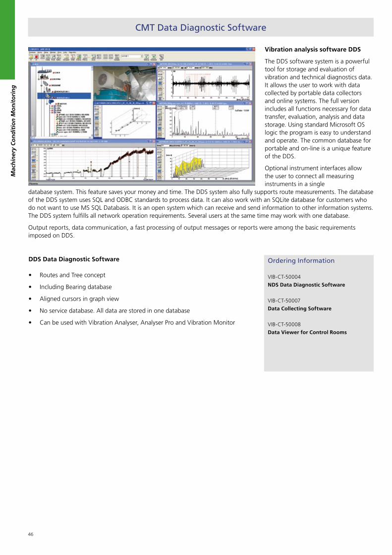
46
Vibration analysis software DDS
The DDS software system is a powerful tool for storage and evaluation of vibration and technical diagnostics data. It allows the user to work with data collected by portable data collectors and online systems. The full version includes all functions necessary for data transfer, evaluation, analysis and data storage. Using standard Microsoft OS logic the program is easy to understand and operate. The common database for portable and on-line is a unique feature of the DDS.
Optional instrument interfaces allow the user to connect all measuring instruments in a single
database system. This feature saves your money and time. The DDS system also fully supports route measurements. The database of the DDS system uses SQL and ODBC standards to process data. It can also work with an SQLite database for customers who do not want to use MS SQL Databasis. It is an open system which can receive and send information to other information systems. The DDS system fulfills all network operation requirements. Several users at the same time may work with one database.
Output reports, data communication, a fast processing of output messages or reports were among the basic requirements imposed on DDS.
CMT Data Diagnostic Software
Mac
hin
ery
Co
nd
itio
n M
on
ito
rin
g
Ordering Information
VIB-CT-50004
NDS Data Diagnostic Software
VIB-CT-50007
Data Collecting Software
VIB-CT-50008
Data Viewer for Control Rooms
DDS Data Diagnostic Software
• Routes and Tree concept
• Including Bearing database
• Aligned cursors in graph view
• No service database. All data are stored in one database
• Can be used with Vibration Analyser, Analyser Pro and Vibration Monitor
47
Water Condition Monitoring
Wat
er C
on
dit
ion
Mo
nit
ori
ng
1. Marine Potable Water Test Kits ................ 48
2. Marine Sewage Water Test Kits .................53
3. Cooling and Boiler Water Test Kits ............55

48
Offshore installations and vessels have a variety of systems that require monitoring for either optimal performance, meeting current or forthcoming legislation and to minimize the risks to the crew or visitor’s Health and Safety on board.
With these in mind, a new range of CMT Marine Water Kits has been developed to assist and adhere with the above requirements.
The systems that will require monitoring are:
• Potable Water
• Sewage Water
• Boiler & Cooling Water
• Ballast Water (coming soon)
According the ever changing legislations CMT is permanently updating the range of Marine Water Test Kits to comply with the current legislations. Currently we are in the process to develop a monitoring equipment to test the ballast water.
Marine Water Test Kits
Potable water is our most important nutrient and is used for both drinking and cooking. The water being used for personal hygiene and all types of cleaning requires the same high quality. It is therefore important to have enough water of satisfactory quality to cover all types of usage.
International regulations regarding the Potable Water Quality Monitoring and Control were driven by the World Health Organization (WHO) via its International Health Regulations (IHR). Soon enough adapted for on-board potable water, as part of the overall Ship Sanitation Certificate.
MLC 2006 does apply to all seagoing vessels and is coming into force on 20th August 2013.
Monitoring and control compliance procedures are laid out in the Guide for Ship Sanitation detailing:
the systems that require monitoring,
the method and frequency of monitoring
the record keeping requirements
Simple regular assessment and testing of the potable water system for microbiological activity, biocide (disinfection control) and implementing a correct control scheme (i.e. temperature monitoring), will ultimately reduce the risk of a disease and save lives.
The CMT Marine Potable Water Test Kits were developed to offer rigs and vessels the complete monitoring solutions for their water systems, with the option of additional extras if required. Suitable control schemes with adequate testing & monitoring will aid with the compliance of the current ILO MLC (2006). These test kits provide real time analysis and simple to perform tests which require no specialist training.
According to ILO MLC (2006) also a qualified person is required on board the vessel or rig to perform the test. CMT provides a complete training for Marine Portable Water Tests to ensure the attendee is qualified to perform all test according the legislations. At the end of the training each attendee will get a certificate proving the respective qualification.
The CMT Marine Water Test Solutions comply with:
• MLC (2006)
• WHO International Health Regulations (2005)
• ILO 178 (2009)
• European Drinking Water Regulations
• Norwegian Drinking Water Regulations (applies for ALL ships calling Norwegian ports!)
Wat
er C
on
dit
ion
Mo
nit
ori
ng
1. Marine Potable Water Test Kit
Portable Water Test Kit
Portable Incubator for Bacterial Test

49
Potable water can contain Microbes that cause infectious disease or food poisoning, such as bacteria, viruses and parasites. Recent high profile legionella on board ships has highlighted issues of crew and passenger health and safety, particularly in respect of microbiological contamination.
Simple, regular testing of the above systems for micro-organisms like legionella, coli forms, e. Coli and pseudomonas will reduce risks and help keep employees healthy.
The CMT Marine Potable Water Quality Test Kit allows you to test for the most critical bacteria’s as well as the main quality parameters. The test kit allows to test the following parameters:
• Total number of bacteria (TVC)
• Coli forms and E. coli
• Pseudomonas
• pH value
• Conductivity
• Total Dissolved Solids (TDS)
• Temperature
Full Compliance Option:
To allow full compliance with international regulations MLC (2006) and ILO 178 including local regulations like the Norwegian Drinking Water Regulations it is essential to do some additional testing not included in the CMT Potable Water Test Kit. Those tests will be provided with the Full Compliance Option from CMT. It is also essential to have a proper record keeping which can be done with the CMT log book provided with the manual in the standard kit. International regulations further specify that a trained person needs to be on-board each vessel or rig to perform the tests. CMT does provide different seminars ensuring proper qualification. A certificate will document the respective qualification. You will find our seminar program at the end of this catalogue.
Ordering Information
WTK-CT-80001
Marine Potable Water Test Kit
WTK-CT-80002
Marine Potable Water Test Cabinet
Contains equipment for:
a) Bacterial Count HTP / TVC (20)
Range: 0-400 CFU/ml
0-1500 CFU/ml
Sample prep.: 1 minute
Incubation: ca. 44 hours
Reagents: non hazardous
Reagent Pack (20) WTK-CT-85001
b) Coliforms / E. Coli (20)
Range: go/ no go
Sample prep.: 1 minute
Incubation: 24 hours
Reagents: non hazardous
Reagent Pack (20) WTK-CT-85002
c) Pseudomonas (20)
Range: go/ no go
Sample prep.: 1 minute
Incubation: 24 hours
Reagents: non hazardous
Reagent Pack (20) WTK-CT-85003
d) pH value (100)
Range: 4,5 – 10 pH
Test time: < 1 min
Reagents: non hazardous
Reagent Pack (100): WTK-CT-85004
e) Conductivity / TDS
Range: 0 – 2000 µS; 2-20mS
0 - 13000 ppm
Accuracy: +/- 2%
Test time: < 1 min
Reagents: non hazardous
Calibration Pack: WTK-CT-85005
f) Temperature
Range: 0-90°C
Accuracy: +/-0,5 °C
Test time: 3 minutes to stabilize
Bacteria Reagent Pack
Bacterial Count HTP Reagent Pack
Coliforms / E.Coli Test
Pseudomonas Test
UV Lamp for Bacteria Test
pH Test Strips
Wat
er C
on
dit
ion
Mo
nit
ori
ng

50
Wat
er C
on
dit
ion
Mo
nit
ori
ng
CMT has developed options for the Marine Potable Water Test Kit which are not needed in general but only if you have certain risk factors. The sanitizer options are depending on which system is used on-board.
Once the potable water is produced or bunkered it is essential to keep the water free of bacteria. There are different ways of treating the water. One common way is to use the ultraviolet light source to remove any possible bacteria before the water is distributed and consumed. Alternatively the water can be ionized with Silver Ions with the advantage of keeping silver ions in the water to deal with any possible bacteria until the water is consumed. Most effective and also very common is to treat the water with chemicals to keep it free of bacterial growth during storage and distribution. Most common on-board seagoing vessels is Chlorine or Chlorine dioxide.
If you use chemicals as sanitizer you will need in addition one of our sanitizer options – depending on what chemical you are using. CMT also provides an option to test for Hardness or Chloride.
There are four sanitizer options available:
Chlorine Comparator Option
Chlorine Drop Test Option
Chlorine Dioxide Option
Silver Ion Option
To measure the effectiveness of treatment chemicals it is important to measure the amount of available chemical to deal with the bacteria.
Therefore CMTs test devices allow to measure the free Chlorine and the free Silver Ions what is not possible in a laboratory since the free ions will be combined once the sample has arrived in the lab. Therefore it is essential to measure this on-board. In a lab it is only possible to measure the combined or total chemical which can be measured on board as well to avoid any health risk or bad taste of the water.
Ordering Information
WTK-CT-80003
MLC 2006 Full Compliance Option
Range:
Colour (100): 0-500 mg Pt/l
Turbidity: 0-1000 FAU
Iron (50): 0.02-2 mg/l
Copper (50): 0.05-5 mg/l
Test Time: 1 minute
Iron Reagent (50): WTK-CT-85006
Reagents: non hazardous
Copper Reag. (50): WTK-CT-85007
Reagents: UN 2680
WTK-CT-80004:
Chlorine Comparator Option
Range free Cl: 0 – 1.0 / 0-3.5 ppm
Range total Cl: 0 – 3.5 / 0-125 ppm
Accuracy: +/- 5%
Test time: 2 / 4 min free / total Cl
Reagents: non hazardous
Reagent Pack (HR): WTK-CT-85008
Reagent Pack (LR): WTK-CT-85009
WTK-CT-80005
Chlorine Dioxide Option
Range : 0 – 0.7 / 0-2 / 0-7 ppm
Accuracy: +/- 10%
Test time: 2 minutes
Reagents: non hazardous
Reagent Pack: WTK-CT-85010
WTK-CT-80006
Free Silver Option/ Consumables
Range: 0 – 100 ppb
Accuracy: +/- 20%
Test time: 3 minutes
Reagents: non hazardous
WTK-CT-80007
Enterococci Option/ Consumables
Range: presence/absence
Accuracy: go/ no go
Sampling Prep.: 1 minute
Incubation: ca. 16-24 hrs
Reagents: non hazardous
Chlorine / Chlorine Dioxide Option
Enterococci Option
MLC 2006 Full Compliance Option
Quelle: Tintometer GmbH
Quelle: Tintometer GmbH
Options for Potable Water Test Kits

51
Legionella is a bacteria which can cause a pneumonia-like disease called “Legionnaires’ Disease”. Infection occurs when the bacteria is inhaled from aerosols of contaminated water. Aerosols can be produced anywhere water is splashed or sprayed but some of the most common sources associated with Legionnaires’ Disease are showers.
Within the Legionella genus there are approximately 50 different species. Several of these can cause infections in people, however worldwide over 90% of infections are caused by a single species: Legionella pneumophila. Within particular “serogroup 1” of pneumophila causing the vast majority (>80%) of all cases, and being implicated in virtually all major outbreaks.
The Legionella Field Test is a breakthrough technology from CMT for the rapid detection of Legionella bacteria in marine potable water systems– delivering test results in minutes instead of days. The test kit contains everything required to perform 10 tests – including sample collection containers and disposable pipettes.
• Optimised for use with hot and cold water systems on-board ships.
• Simple to use and fast, with no interpretation required.
• Results are easy to read and obtained within 25 minutes.
• No chemicals to measure or handle.• Immediate understanding and
response to the water conditions.• Reduce risk of outbreaks and
litigation.• Increase confidence in your
Legionella control.
The CMT Legionella Field Test uses an immunochromatographic assay, to detect the presence of cell surface antigens from Legionella bacteria in a sample. The presence of antigen causes the “Test Line” to turn red in colour. A “Control Line” is included which should always turn red if the test has been performed correctly.
Ordering Information
WTK-CT-80010
CMT Legionella Field Test Kit (10)
Detection Limit: 100 CFU/ml
Operator Time: < 2 min
Development Time: 25 min
Shelf Life: min 12 month
Sample Parameter: pH 5 – 10 / 15 – 40 °C
Singel Legionella Test
Legionella Option
Simple Steps for Legionella TestW
ater
Co
nd
itio
n M
on
ito
rin
g

52
Wat
er C
on
dit
ion
Mo
nit
ori
ng
Ordering Information
WTK-CT-85012
Conductivity / TDS Meter
Range: 0 – 2000 µS; 2-20mS
0 - 13000 ppm
Accuracy: +/- 2%
Test time: < 1 min
Reagents: non hazardous
Calibration Pack: WTK-CT-85005
WTK-CT-85013
pH Meter
Range: pH: -2 - 16
Temp: 0 - 90 °C
Accuracy: +/- 0.02 pH / 0.3 °C
Test time: < 1 min
Reagents: non hazardous
Buffer Solution 4,0: WTK-CT-85014
Buffer Solution 7,0: WTK-CT-85015
Buffer Solution 10,0: WTK-CT-85016
WTK-CT-80008
Potable Chloride Option/ Consumables
Range: 20-400 ppm
Test Time: 3 minutes
Reagents:
WTK-CT-80009
Potable Hardness Option/ Consumables
Range: 0.5-60 ppm
Test time: 3 minutes
Reagents: UN 3267
CMT has developed further options for the Marine Potable Water Test Kit to test for water properties.
Conductivity is an indirect measure of total dissolved solids. Typical values (approximately) for untreated distillates is 50 µS/cm. Water from shore sources should have around 500 µS/cm. Seawater has about 50,000 µS/cm. Therefore high conductivity could be an indication for seawater ingress. Too low conductivity should trigger evaluation of corrosive processes in the piping and existiong of heavy metals due to corrosion.
Ideal pH value depends on the materials used. A pH value above 8 does not allow effective water disinfection with chlorine and gives evidence that self produced water may not be re-mineralized adequately. Further assessment of water quality should be performed.
Chloride is a clear evidence of seawater in the potable water. Normal values are between 10 - 30 ppm. Values above 250 ppm dose give the potable water a salty taste and should therefore be avoided.
Hardness below 60 mg/l poses high risk of copper corrosion. Too low hardness should trigger evaluation of corrosive processes in the piping and existing of heavy metals in the potable water due to corrosion.
pH / Temp Meter Conductivity / TDS Meter
Chloride / Hardness Option
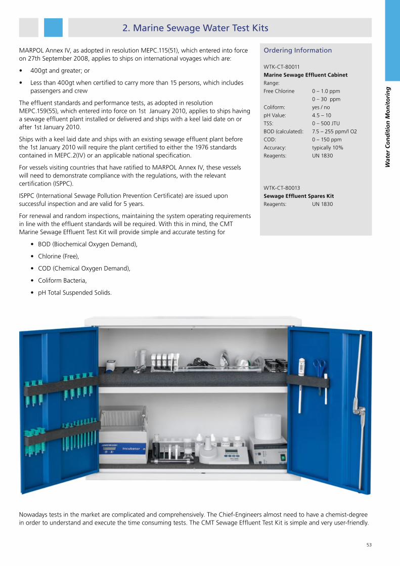
53
2. Marine Sewage Water Test Kits
MARPOL Annex IV, as adopted in resolution MEPC.115(51), which entered into force on 27th September 2008, applies to ships on international voyages which are:
• 400gt and greater; or
• Less than 400gt when certified to carry more than 15 persons, which includes passengers and crew
The effluent standards and performance tests, as adopted in resolution MEPC.159(55), which entered into force on 1st January 2010, applies to ships having a sewage effluent plant installed or delivered and ships with a keel laid date on or after 1st January 2010.
Ships with a keel laid date and ships with an existing sewage effluent plant before the 1st January 2010 will require the plant certified to either the 1976 standards contained in MEPC.2(IV) or an applicable national specification.
For vessels visiting countries that have ratified to MARPOL Annex IV, these vessels will need to demonstrate compliance with the regulations, with the relevant certification (ISPPC).
ISPPC (International Sewage Pollution Prevention Certificate) are issued upon successful inspection and are valid for 5 years.
For renewal and random inspections, maintaining the system operating requirements in line with the effluent standards will be required. With this in mind, the CMT Marine Sewage Effluent Test Kit will provide simple and accurate testing for
• BOD (Biochemical Oxygen Demand),
• Chlorine (Free),
• COD (Chemical Oxygen Demand),
• Coliform Bacteria,
• pH Total Suspended Solids.
Ordering Information
WTK-CT-80011
Marine Sewage Effluent Cabinet
Range:
Free Chlorine 0 – 1.0 ppm
0 – 30 ppm
Coliform: yes / no
pH Value: 4.5 – 10
TSS: 0 – 500 JTU
BOD (calculated): 7.5 – 255 ppm/l O2
COD: 0 – 150 ppm
Accuracy: typically 10%
Reagents: UN 1830
WTK-CT-80013
Sewage Effluent Spares Kit
Reagents: UN 1830
Nowadays tests in the market are complicated and comprehensively. The Chief-Engineers almost need to have a chemist-degree in order to understand and execute the time consuming tests. The CMT Sewage Effluent Test Kit is simple and very user-friendly.
Wat
er C
on
dit
ion
Mo
nit
ori
ng

54
Wat
er C
on
dit
ion
Mo
nit
ori
ng
Regular testing will allow rapid corrective action to take place if required, helping to maintain optimum operating conditions, minimum downtime and reducing costs. Ultimately the CMT Marine Effluent Cabinet will aid compliance with MARPOL Annex IV.
The CMT Marine Water Test Solutions comply with:
• MARPOL Annex IV: Resolution MEPC.2 (IV)
• MARPOL Annex IV: Resolution MEPC.115 (51)
• MARPOL Annex IV: Resolution MEPC.159 (55)
In line with new IMO / MARPOL regulations, CMT has developed a simple and effective way to test sewage water onboard. The test is a requirement to be executed before you are allowed to enter many ports today, also it will be compulsory across the whole globe.
The discharge of raw sewage into the sea can create a health hazard, while in coastal areas sewage can also lead to oxygen depletion and an obvious visual pollution.
Environmental issues are still a hot topic these days. The shipping community expresses its concern about the ecosystem and the pollution of the seas. In this market where low freight rates, new rules and regulations and a higher customer demand are pressuring our business-results, we still desire to comply with new rules and regulations but preferably in a cost-effective and efficient way
To test the discharge of Sewage treatment plants CMT offers a quick and easy drop test for testing of the free chlorine content
Ordering Information
WTK-CT-80023:
Chlorine (free) Drop Test Option
Range free Cl: 0 – 30 ppm
Accuracy: +/- 10%
Test time: 2 / 4 min
Reagents: non hazardous
Reagent Pack: WTK-CT-85023

55
3. Cooling and Boiler Water Test Kits
Engine cooling systems contain carefully blended additives that prevent scale deposits and corrosion of engine waterways. It is very important that the concentration of the additive is maintained at the correct level for optimum protection.
Every industry that operates boiler and cooling water systems – ranging from power plants, vessles or other industrial plants – needs to regularly test the water to analyze a number of parameters. This is imperative as it avoids corrosion and malfunction. CMT offers the ideal solution for all specific requirements.
CMT is dedicated to providing our customers with the most convenient, reliable and secure systems for all analyses purposes. To specifically serve all industries that employ or deal with
boiler and cooling water systems, our new range of test kits has been developed.
CMT supply treatment test kits for engine cooling water and steam boiler water. The kits are very simple to operate and will enable the ships engineer to monitor scale and corrosion inhibitor concentrations. Regular testing will allow rapid corrective action to take place helping you to maintain optimum operating conditions, minimise down-time and reduce energy costs.
Low and medium pressure steam boilers are treated with special corrosion and scale inhibitors. It is vitally important to maintain precise levels of these additives to ensure correct and efficient steam generation. Failure to regularly maintain and monitor treatments will inevitable end in system failure and expensive corrective maintenance.
Ordering Information
WTK-CT-80015
Cooling Water Test Kit
100 x Chloride LR (20-400 ppm)
100 x Nitrite (75-2500 ppm)
100 x pH Test Stripes (pH 4,5-10)
WTK-CT-80018
Boiler Water Test Kit (I) Low Pressure
100 x Chloride LR (20-400 ppm)
100 x P-Alkalinity (40-400 ppm)
100 x pH Test Stripes (pH 7-14)
WTK-CT-80019
Boiler Water Test Kit (II) High Pressure
100 x Chloride HR (200-1200 ppm)
100 x Alkalinity (40-400 ppm)
100 x pH Test Stripes (pH 7-14)
Wat
er C
on
dit
ion
Mo
nit
ori
ng

56
Wat
er C
on
dit
ion
Mo
nit
ori
ng
To measure Chloride in cooling water treated with the corrosion inhibitor Glysacorr G-93/94 the standard Chloride test, also from other suppliers, will not work. To specifically serve our customers using Glysacorr G-93/94 as additive, the new Glysacorr Chloride Test Kit has been developed.
To measure the level of Glycol in cooling water CMT also provides a Glycol Refractometer. The Refractometer allows easy tests of the level for Propylene and Ethylene Glycol up to 70% securing a protection down to -50 °C.
Ordering Information
WTK-CT-80016
Glysacorr Chloride Test
Range: (50-300 ppm)
WTK-CT-80017
Glycol Refractometer
Range: 0-70%
WTK-CT-85013
pH Meter
Range: pH: -2 - 16
Temp: 0 - 90 °C
Accuracy: +/- 0.02 pH / 0.3 °C
Test time: < 1 min
Reagents: non hazardous
Buffer Solution 4,0: WTK-CT-85014
Buffer Solution 7,0: WTK-CT-85015
Buffer Solution 10,0: WTK-CT-85016
Benefits:
• Optimise operating conditions
• Reduce energy costs
• Measure key boiler and cooling water inhibitors
• Simple step-by-step instructions

57
Complete Monitoring Solutions
1. PLC Based Central Unit............................. 59
2. Control Panel ........................................... 60
3. CMS Options ........................................... 61
4. Application Specific Solutions .................. 63
Co
mp
lete
Mo
nit
ori
ng
So
luti
on
s
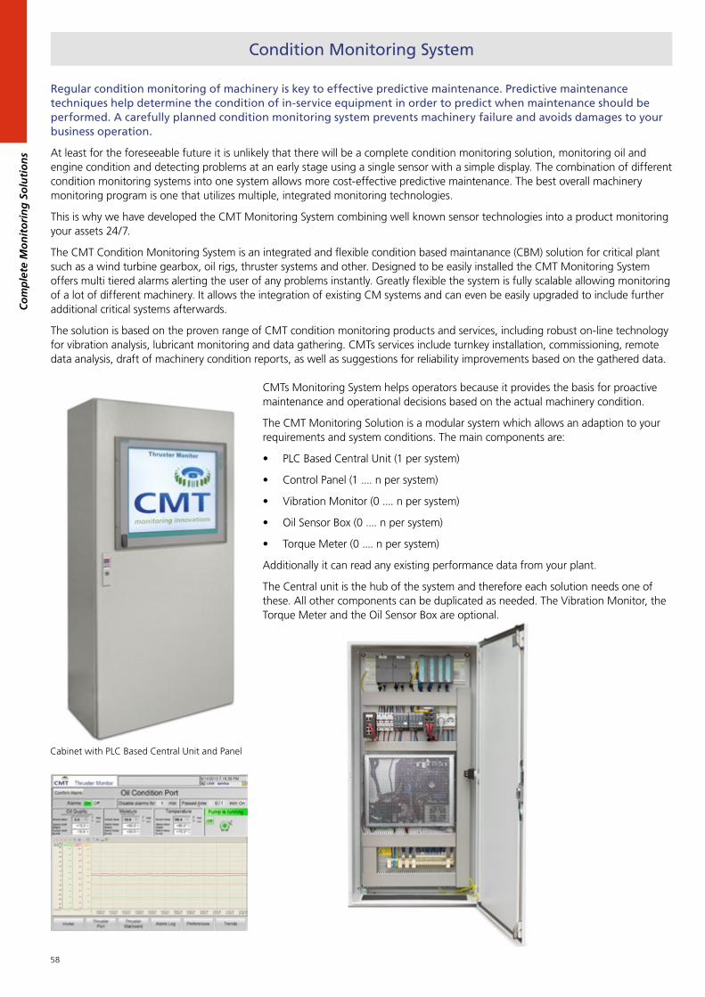
58
Co
mp
lete
Mo
nit
ori
ng
So
luti
on
s
Regular condition monitoring of machinery is key to effective predictive maintenance. Predictive maintenance techniques help determine the condition of in-service equipment in order to predict when maintenance should be performed. A carefully planned condition monitoring system prevents machinery failure and avoids damages to your business operation.
At least for the foreseeable future it is unlikely that there will be a complete condition monitoring solution, monitoring oil and engine condition and detecting problems at an early stage using a single sensor with a simple display. The combination of different condition monitoring systems into one system allows more cost-effective predictive maintenance. The best overall machinery monitoring program is one that utilizes multiple, integrated monitoring technologies.
This is why we have developed the CMT Monitoring System combining well known sensor technologies into a product monitoring your assets 24/7.
The CMT Condition Monitoring System is an integrated and flexible condition based maintanance (CBM) solution for critical plant such as a wind turbine gearbox, oil rigs, thruster systems and other. Designed to be easily installed the CMT Monitoring System offers multi tiered alarms alerting the user of any problems instantly. Greatly flexible the system is fully scalable allowing monitoring of a lot of different machinery. It allows the integration of existing CM systems and can even be easily upgraded to include further additional critical systems afterwards.
The solution is based on the proven range of CMT condition monitoring products and services, including robust on-line technology for vibration analysis, lubricant monitoring and data gathering. CMTs services include turnkey installation, commissioning, remote data analysis, draft of machinery condition reports, as well as suggestions for reliability improvements based on the gathered data.
CMTs Monitoring System helps operators because it provides the basis for proactive maintenance and operational decisions based on the actual machinery condition.
The CMT Monitoring Solution is a modular system which allows an adaption to your requirements and system conditions. The main components are:
• PLC Based Central Unit (1 per system)
• Control Panel (1 .... n per system)
• Vibration Monitor (0 .... n per system)
• Oil Sensor Box (0 .... n per system)
• Torque Meter (0 .... n per system)
Additionally it can read any existing performance data from your plant.
The Central unit is the hub of the system and therefore each solution needs one of these. All other components can be duplicated as needed. The Vibration Monitor, the Torque Meter and the Oil Sensor Box are optional.
Condition Monitoring System
Cabinet with PLC Based Central Unit and Panel

59
Co
mp
lete
Mo
nit
ori
ng
So
luti
on
s
1. PLC Based Central Unit
Ordering Information
CMS-CT-13005
PLC Based Central Unit
The Siemens PLC based Central Unit is the heart of the CMT Monitoring System. It collects all information and controls the entire system. The gathered data is being pre-processed and then data packages and access are being provided to the CMT Control Panel.
CMTs latest generation of monitoring systems comes with a rugged enclosure, high electromagnetic compatibility (EMC) and a protection rating up to IP65. The Central Unit is highly vibration and shock resistant thanks to the used components like for example SSD drives. Connectors and card retainers are all lockable.
With its diverse product features and the available additional system upgrades the Central unit ensures a long term plant availability and cost effectiveness while also reducing any follow up costs.
The modular unit allows maximum flexibility for any requirements our customers may have. Almost any number and type of inputs can be processed with the new Central Unit. This also allows an easy extension of the system at a later stage.
The unit will be supplied in a cabinet ready to be installed. Optionally it can also house the Vibration Monitor and the control panel.
PLC Based Central Unit (Source: SIEMENS)

60
Co
mp
lete
Mo
nit
ori
ng
So
luti
on
s
Specification Display Panel
Power supply 230 V AC 50/60 Hz
Display 19 inch wide screen (1280 x 1024)
Connectivity 1 x USB on front
Sealing IP 65
Operating System Windows 7 Ultimate
Data storage 50 GB SSD
Processor Intel Core i7 (2.53 Ghz)
Network 2 x Gigabit Ethernet, 1 x PROFIBUS, 1 x PROFINET
Operating Temp. 0 - 50 °C
Shock / Vibration 5 g / 1 g
Ordering Information
CMS-CT-13002
Control Panel for installation in console
CMS-CT-13006
Control Panel with housing for wall
mounting or desktop installation
CMS-CT-13007
Additional Display for installation in
console
CMS-CT-13008
Additional Display with housing for
wall mounting or desktop installation
Benefits:
• Cast aluminium front for 24 hours continuous operation, also for high temperatures, vibration, shock and EMC requirements.
• Energy saving LED backlight (100% dimmable) guarantees an especially long service life
• High resolution wide screen display
• Good readability from all directions
• Very long-term availability
2. Control Panel
The Control Panel is a Siemens industrial PC made to be used in harsh environments. It provides an easy to understand graphical overview about your equipment and controls the entire CMT Monitoring System. Equipped with the 3rd generation of Intel Core i7 processors it ensures highest performance. Based on the Windows 7 operating system it is responsible for the final data processing, data storage and all display functions. Its functionality also includes to set up the entire system including alarm levels etc.
The 19 inch touchscreen allows easy control of all information. The main functions of the CMT Control Panel are:
• Displaying the current condition of the equipment monitored
• Highlighting any problems, setting and controlling alarms
• Data storage and display of historical data
• Data export for example via USB or as email to preset recipients to enable remote data analysis and control
• System set up
Industrial PCs from Siemens veritably comply with the highest quality standards associated with the “Made in Germany” label. This is ensured by German developed main boards and innovative technologies for reliable continuous operation in an industrial environment. Integrated quality assurance concept - maximum quality right from the start.
Control Panel
USB Port on Panel (Source SIEMENS)

61
Ordering Information
VIB-CT-50003
CMT VibrationMonitor
VIB-CT-50005
Acceleration Sensor 100 mV/g
VIB-CT-50015
Connector for Acceleration Sensor
VIB-CT-50006
Tacho Probe
VIB-CT-50009
5 m Extension Cable for Sensor or Tacho
VIB-CT-50010
10 m Extension Cable for Sensor or Tacho
VIB-CT-50011
Standard Measuring Pad with
Plastic Cover a 10 pcs.
VIB-CT-50018
Epoxy Metal Glue for Measuring Pads
3. CMS Options
Vibration monitoring is the most common method for condition monitoring. However, also this technology does have its limitations and should therefore be only one part of a complete monitoring system.
Each Vibration Monitor module contains 16 AC, 16 DC and 4 TACHO inputs. All 16 channels are measured simultaneously. The CMT condition monitoring system can operate with several Vibration Monitor units. For a high number of vibrational measuring points CMT does provide a Multiplex unit allowing to connect up to 64 vibration sensors to one Vibration Monitor unit. With the Multiplex unit 4 times 16 points are measured in sequences.
he Vibration Monitor can measure the acceleration in up to 16 different places simultaneously. At the same time it can measure up to 4 different rotational speeds. A real time spectral analysis is provided to get the acceleration and velocity in a high resolution spectrum with up to 56,000 lines. Furthermore the enveloped signal is analysed.
The Vibration Monitor can measure the acceleration in up to 16 different places simultaneously. At the same time it can measure up to 4 different rotational speeds. A real time spectral analysis is provided to get the acceleration and velocity in a high resolution spectrum with up to 56,000 lines. Furthermore the enveloped signal is analysed.
Data is transferred via an OPC server to the Control Panel. At the control panel RMS values are shown only at a very narrow band at fault frequencies for the bearings or at the gear mesh frequency. To detect threats to the general system condition like imbalances, loose feet or misalignments the velocity is monitored at nominal, double and triple rotational speed frequency.
This allows the end user to trend single numbers instead of evaluating expert level FFT diagrams. A customisable traffic light alarm system is being used for a simple and understandable display of the condition.
Vibration Monitor
Condition Monitoring tools have become smaller, lighter, faster and more sophisticated in recent years. Functionality that once was limited to a computer in an office can now be easily done in the field with the right CM analysis tool. It is now possible to do complete equipment analysis at the machine.
The best overall machinery monitoring program is one that utilizes multiple, integrated monitoring technologies that are well-suited to detect expected failures modes.
The hub components of the CMT Monitoring System have no measuring functionality of themselves because they are taking care of the various input signals and data services.
The actual readings of the different indicators are being
handled by options which can be combined freely according to our customers needs.
Currently available standard options are:
• Lubrication oil parameters• Vibration Monitoring• Torque / Power Monitoring
The system allows to add any number of inputs from other control systems already in use. This allows a complete condition and performance monitoring of your equipment.
Various different interfaces are available to read in analog or digital third party signals.
Cabel into the main box for Vibration Monitor
Vibration sensor with pad, connector and cable
Co
mp
lete
Mo
nit
ori
ng
So
luti
on
s

62
Individual Oil Sensor Suites are installed local to each thruster measuring the following parameters:
• Metallic Particle
• Oil Condition
• Moisture Sensor
• Oil Temperature
• Flow (yes / no)
Additional parameters are available on request.
Sensor Boxes are being provided including a pump to guarantee effective oil circulation.
Co
mp
lete
Mo
nit
ori
ng
So
luti
on
s
Oil Sensor Box
Consisting of a combination of oil sensors, the Oil Sensor box has been developed to offer real-time monitoring of oil on critical plant such as a wind turbine gearbox. The Sensor Box makes frequent inspections of remote oil and machine health a feasible option. The risk of sampling error is eliminated and data from the sensors can be streamed via any network system, allowing remote monitoring and increasingly effective maintenance planning.
Designed for mounting into the lubrication system of a machine, the sensor box reports optional metallic particle, oil condition, moisture content of the oil or viscosity. The Sensor Box is part of the CMT Thruster Monitor System.
Torque Meter
The CMT Torque Meter is a permanent monitoring system which continuously measures the shaft (effective) torque, and RPM. The torque meter itself consists of two metal strips with a magnetic pattern, two sensors and a transmitter. It is 24 V (DC) powered, with 2 x 4-20mA current outputs, a pulse RPM output and a serial port (RS232 or USB).
The CMT Torque Meter Software has been developed to enable ship owners to monitor the energy efficiency performance of their ships to comply with the SEEMP demands. SEEMP, designed by the IMO to encourage best practices for the fuel efficient operation of ships, has become mandatory from January 2013. It is a requirement for all owners and operators of ships over 400 GT to detail measures that are being implemented to reduce fuel consumption and thus lower greenhouse gases and other emissions.
Benefits
• Digital method of shaft twist measurement, not affected by changes in temperature, propeller thrust or shaft misalignment and stress.
• Contact free digital sensors.• High precision - time resolution of 0.1 milliseconds.• Simple & easy to install also for retrofit installations.• No need to provide power to the components on the shaft.• No need to transfer any signals by telemetry from rotating components.• Simple zero calibration procedure.• User friendly and maintenance free
Ordering Information
TQM-CT-18319:
Torque Meter
Contact- free method for permanent torque
& power measurement
Online Oil Sensors:
• Ensure good lubricant condition.
• Control contamination.
• Control the wear rate to ensure
longer service life.
• Increase the surveillance level of the
machine between oil samples.
• Low cost of purchase and
ownership.
• Minimal annual servicing costs.
• Minimal installation costs.
Ordering Information
CMS-CT-13009
Standard Oil Sensor Box
Contains:
- Metallic Particle
- Oil Condition
- Moisture
- Flow Control
- Oil Pump
(Additional parameters are available on
request.)
Sealing: IP 65
Oil Sensor Box

63
4. Application Specific Solutions
The CMT Condition Monitoring System is modular and flexible and can be used for monitoring most equipment. On the other hand this means a lot of customising for each application taking time and adding cost to the system.
To help our customers to find the right solution for their systems CMT has come up with standard application specific solutions. These innovations are already specified to our best knowledge of the equipment and can be used by our
customers as off the shelf solution if they do not want to invest in a fully customized system.
Although specifically put together they still can be modified to meet your exact monitoring requirements. At the same time they combine our experience from previous similar monitoring tasks and installations to give you the best monitoring performance.
CMT Liner Monitor
The CMT Liner Monitor is providing an early warning of an impending critical engine damage due to mechanical or corrosive wear. Furthermore the information provided can be used to optimise your cylinder oil consumption.
Trials show that Liner Monitor highlights the first signs of damage earlier than other systems and enables a safe reduction of the lubricant feed rate. At the same time it monitors any acid corrosion problem inside the combustion chamber. Liner Monitor is an automated system helping you to save money by optimizing the lubricant feed rate while avoiding any acid corrosion. It reduces your maintenance costs and helps to prevent unnecessary engine damage.
CMT’s Liner Monitor system is designed to remove the uncertainty of not knowing if there is any cylinder damage resulting from low fuel quality, slow steaming, low or high sulphur levels, lower oil feed rates and cylinder oil formulation changes.
The picture shows a typical installation place for the Liner Monitor Benefits:
• Enables safe reduction of cylinder oil feed rates while keeping the acid corrosion under control.
• Reduce engine damage by spotting the first signs of scuffing, piston ring damage or other wear problems.
• Gives an early indication about CAT fines related problems.
• Allows an informed running-in process based on real wear data.
• Simple installation for both new and retrofit.
Ordering Information
CDO-CT-10001
Liner Monitor Sensor
CDO-CT-10010
Liner Monitor Control System
Operating System: Windows 7 32 bit
Screen Resolution: 1280 x 1024 min.
CDO-CT-10030
CDO Sampling Section
Length: 240 mm
Pipe: Ø 60-80 mm
Flange: DIN 3 inchC
om
ple
te M
on
ito
rin
g S
olu
tio
ns
Coming Soon

64
Ordering Information
CMS-CT-13001
Thruster Monitoring Unit (One per
Thruster)
CMS-CT-13002
Master Control Panel (One per System)
CMT Thruster Monitor
Co
mp
lete
Mo
nit
ori
ng
So
luti
on
s
The propulsion units of a vessel or rig are inspected via regular checks and are protected by standard alarm systems.
The alarm will only indicate that the condition has reached an unacceptable level, in which case the system must be stopped for maintenance. Regular checks carried out every 2.5 to 5 years, as prescribed by the appropriate class society, may visualize a changing condition. However, in order to enable effective preventative actions to be taken before serious breakdowns occur, it is worthwhile having a CMS of the propulsion and steering devices. At sea, the distance between the operational areas, harbours, or docking facilities, are wide, and docking facilities are not even always available. There are, sometimes, possibilities to employ underwater exchangeable thrusters, but such downtime interrupts the operation and is not always affordable. In offshore operations, this type of work causes a tremendous loss of production.
In addition to the control and alarm system, it is recommended having a CMS that uses accelerometers, oil sensors, and signals from the existing sensors for the controls.
Oil Sensor Box installed on a Sismic Vessel
Examples of available screens in Thruster Monitor:
Underwater part of a typical thruster
New

65
The CMT Thruster Monitor is an integrated and flexible condition based maintenance solution for propulsion and positioning thrusters (tunnel and azimuth thrusters) in the marine and offshore industry.
CMT’s Thruster Monitor keeps you informed about the thruster condition and gives real-time feedback on the effect of altering operating parameters.
There is a preference in the marine industry to combine existing systems into one system. The CMT Thruster Monitor can integrate with thruster and ship management systems.
The Thruster Monitor is available for ship operators and thruster manufacturers. It can easily be installed as retrofit on existing vessels as well as on new buildings.
CMT´s Thruster Monitoring Systems system can be used for all markets and types of thrusters across various sectors of the marine industry. It is a totally modular system allowing to meet your requirements exactly.
The Thruster Monitor assists ship or rig operators in achieving CBM requirements from classification societies. It also provides the basis for proactive maintenance and operational decisions based on actual thruster conditions.
Don’t leave your thruster condition to chance. Avoid unnecessary repairs and thruster changes by monitoring your system. This will allow you to extend the life time and to schedule down times.
Your benefits
• Will allow extended class survey intervals
• Reduced need for dry docking
• Higher availability of ships or rigs
• Remote system control and data access
• On-screen trending of all parameters
• Fully automated operation
Avoid unnecessary changes of your thruster
Cable into the main box for Thruster Monitor Vibration sensor with pad, connector and cable
Typical installation sceme for one thruster
Co
mp
lete
Mo
nit
ori
ng
So
luti
on
s

66
Co
mp
lete
Mo
nit
ori
ng
So
luti
on
s
CMT Offshore Wind Turbine Monitor
Renewable energy sources like wind energy are copiously available without any limitation. Wind turbines are used to tap the potential of wind energy, which is available in millions of of megawatts.
Reliability of a wind turbine is critical to extract the maximum amount of energy from the wind.
The operational cost of offshore wind turbines are very high. For offshore wind energy the cost for operation and maintenance are estimated at about 1/3 of the cost of electricity.
The revenue losses for offshore wind turbines can be significant whereas for onshore projects the revenue losses are negligible.
To reduce the cost for corrective maintenance condition monitoring and
diagnostic practices have become a significantly important part especially for offshore wind farms in order to cut down operation and maintenance costs.
The challenge is to enable Condition Based Maintenance (CBM) strategy to be implemented to provide maintenance decisions and services at the right time.
Offshore wind turbines will benefit most from the fact that with early fault detection, repairs can be better planned. This will lead to shorter downtimes and less revenue losses. Condition monitoring is important for early fault detection to prevent any catastrophic conditions due to sudden breakdowns.
Ordering Information
CMS-CT-13010
Offshore Wind Turbine Monitor
CMT Offshore Wind Turbine Monitor combines vibration analysis with oil condition monitoring. Performance data can be monitored at the same time.
Data can easily be monitored from remote locations. Alarms are generated automatically and can be sent by email or SMS.
New
67
Sampling Solutions
Sam
plin
g S
olu
tio
n
1. Drip Type Bunker Sampler Flange ............. 68
2. Fuel Sampler .............................................69
3. Marpol Bunker Cabinet .............................70
4. Automatic Fuel Sampler ............................71
5. Vacuum Sampling Pump ..........................72
6. Sampling Bottles and Accessories .............73

68
Sam
plin
g S
olu
tio
ns
Sampling Solutions
One of the most important aspects of any oil analysis program is the sampling method and the sampling equipment used. The sample needs to be representative for the total amount and uncontaminated. Oil samples are required for regulatory analysis but also for commercial and regulatory purposes.
A representative oil sample will provide an accurate representation of the contaminants, additives, oxidation, particulates and wear condition. If a sample does not represent the real condition of the oil and component at the time of sampling, the reliability of both the test result and it’s interpretation is in doubt.
Representative fuel oil samples are required for both regulatory and commercial purposes. Crucial aspects of the sampling process include taking the sample, the sampling location and witnessing the process.
CMT’s sampling solutions provide you with everything you need to easily gather an uncontaminated, representative sample of your running liquids.
Using a so called drip sampler is the most common and economic way to obtain a representative sample according MARPOL 73/78 Annex VI.
Our bunker samplers are:
• manufactured under strict ISO 9001 quality assurance standards.
• compliant with IMO MARPOL 73/78 Annex VI helping you to stay within the legal requirements for bunker fuel sampling.
• weight optimized.
• simple to install on all common flanges between 2” and 14”.
• one size sampler can be used on most common different standard flanges even for different pressure. .
.In cases where you have a negative pressure at the point of sampling please use our automatic samplers
Material: Stainless Steel 1.4571 / 316TiNominal Flange Thickness: 25/26 mmTotal Thickness (Including gaskets): 31/32 mm
Selecting the Correct Size of Drip Type Bunker Sampler
Select the nearest size Bunker Sampler with an outer diameter smaller than the flanges Pitch Circle Diameter minus the flanges Bolt Hole Diameter.
The inner diameter must be larger than the Nominal Pipe Size of the flange.
1. Drip Type Bunker Sampler Flange

69
2. Fuel Sampler
Normally samplers are installed at the ships manifold between the manifold flange and the flange from the bunker hose.
However, sometimes it is more practical to install the sampling device permanently at a different place. The CMT Fuel Sampler is designed to be installed direct into an existing fuel pipe.
It can easily be removed for cleaning. After initial installation the fuel line can be used with or without the sampler being inserted.
Benefits:
• Designed specifically for fuel oils• Easy retrofit• Service pipes from 2 inch up to 14
inch• Compliant with ISO 3170
Ordering Information Flange (other sizes are available on request) - Material: Stainless Steel 1.4571 / 316T
Part Number Nominal
Pipe Size
Inner
Diameter
Outer
Diameter
Weight Flange Standard Correlations
SAM-CT-10002 50 mm/2” 63 mm 95 mm 3.5 kg JISB2210 5K, 10K, 16K, BS 4504 PN10, PN16, BS10 D, E, F, ANSI B16.5
150, 300
SAM-CT-10003 75 mm/3” 86 mm 127 mm 4.0 kg JISB2210 5K, 10K, 16K, BS 4504 PN16, BS10 D, E, F, ANSI B16.5 150,300
SAM-CT-10004 100 mm/4” 116 mm 157 mm 4.3 kg BS 4504 PN16, BS10 D, E, F ANSI B16.5 150, 300
SAM-CT-10005 125 mm/5” 144 mm 188 mm 5.0 kg JISB2210 5K, 10K, 16K, BS 4504 PN16, BS10 D, E, ANSI B16.5 150
SAM-CT-10006 150 mm/6” 171 mm 216 mm 5.5 kg JISB2210 5K, 10K, 16K, BS 4504 PN10, PN16, BS10 D, E, F, ANSI B16.5
150, 300
SAM-CT-10007 175 mm/7” 194 mm 241 mm 6.2 kg JISB2210 5K, 10K
SAM-CT-10008 200 mm/8” 221 mm 266 mm 6.5 kg JISB2210 5K, 10K, 16K, BS 4504 PN10, PN16, BS10 D, E, F, ANSI B16.5 150
SAM-CT-10009 225mm/9” 260 mm 307 mm 6.7 kg ANSI B16.5 300
SAM-CT-10010 250mm/10” 281 mm 328 mm 7.1 kg JISB2210 10K, 16K, BS 4504 PN10, PN16, BS10 D, E, F, ANSI B16.5 150,
300
SAM-CT-10011 275mm/11” 319 mm 361 mm 7.2 kg JISB2210 10K, BS 4504 PN10, PN16, BS10 d, E
SAM-CT-10012 300mm/12” 340 mm 401 mm 7.5 kg JISB2210 16K, BS10 F, ANSI B16.5 150, 300, BS 4504 PN10, PN16, BS10
D, E, F
SAM-CT-10014 350mm/14” 375 mm 420 mm 8.0 kg ANSI B16.5 150,300
Ordering Information
SAM-CT-14000
Fuel Sampler
Size: 2” - 14”
50 - 350 mm
Weight: 2.0 kg
Sam
plin
g S
olu
tio
ns

70
3. MARPOL Bunker Cabinet
Ordering Information
SAM-CT-20000
MARPOL Bunker Cabinet
Content:
- 40 Sample Bottles and Mailer Kit
- 45 MARPOL Fuel Sample Label
- 45 Clear Adhesive MARPOL Over Label
- 40 Seals for bottles and sampler
- 24 Cubitainer (5 litre)
The CMT MARPOL Bunker Sample Storage Cabinet is a complete unit providing everything needed to comply with the IMO MARPOL regulations. It contains everything for collection, retention and storage of bunker fuel oil samples as required by the IMO MARPOL Annex VI regulations.
The bunker sample collection and storage is defined in MEPC.96(47). In the guidelines it is defined that a retained sample of all fuel oil as supplied, is drawn at the ships receiving manifold, sealed, signed and then retained under the ship’s control until the subject fuel has been substantially consumed, but for at least 12 months from the date of delivery.
• A robust, fully lockable metal case allows the safe and secure sample storage according the regulations.
• Everything you need is provided in the same cabinet ensuring compliants with IMO MARPOL 73/78 Annex VI regulations.
• Its supplied with log book to record your sample details.
Replacement consumable and a full range of drip type or automatic bunker samplers are easily available at short notice on request.
Sam
plin
g S
olu
tio
ns

71
Especially bigger vessels are facing the problem of negative pressure at the bunker manifold. Traditional Drip Samplers cannot be used here. They need a positive pressure to allow the sample to flow into the sample container by gravity. The solution is the Automatic Fuel Sampler which does work with vacuum up to -0.8 bar.
The Automatic Sampler is connected to the main bunker line by a flexible hose for the mobile solution or by pipe fittings for the permanent installed version. After start it will automatically sample into the cubitainer and stop after the preset bunker time. The sampler can sample into all size bottles or cubitainers. On special request we can provide a version which can sample into up to 5 individual sample bottles simultaneously or in a sequence. For highest flexibility
the sampler can either be mounted on a trolley or permanently installed next to the manifold.
The standard version works as time proportional sampler ensuring a representative sample. For applications with changing flow rates we also offer a flow proportional version.
Because of ATEX regulations the sampler does not use electricity. All our samplers are pneumatically driven with normal working air between 6 and 8 bar. The samplers can be used under all weather conditions. All fittings are made from stainless steel AISI 316, designed and produced to survive in a harsh environment.
This Automatic Fuel Sampler is mounted on a trolley to easy restore after bunkering. The waterproof sampler is equipped with a flushing tank and made of stainless steel. It does have a DNV type approval and complies with MARPOL Annex VI.
The sampler is also available as a wall mounted version
The heavy duty sampler can be installed right on the manifold. It is fully pneumatic driven with bunker timer and does have an automatic stop function. This model is also produced in a low temperature version.
This very advanced automatic Fuel Sampler, which can sample into 4 bottles simultaneously, is very popular on bunker barges but is also used on merchant ships.
The sampler can sample under all conditions even with very high negative pressure in the bunker line and does give you four most representative samples. This sampler is optional also available for 5 bottles.
The sampler is also available as a vertical wall mounted version.
In addition to the Type 50 specification it does come with a circulating pump to have a heating functionality. It does also have a DNV type approval and complies with MARPOL Annex VI.
Ordering Information
SAM-FS-05051
Automatic Fuel Sampler Type 50
Size: 350 x 250 x 500
With trolley: 1100 x 500 x 500
Weight: 15 / 40 kg
Material: AISI 316
Compressed Air Pressure
Max. pressure: 12 bar
Normal pressure: 6-8 bar
Fuelline pressure
Standard: -0.4 bar
Optional -0.8 bar
Bunker Timer: 1 – 16 hours
Ordering Information
SAM-FS-07014
Automatic Fuel Sampler Type 70
Size: 600 x 600 x 600
Weight: 35 / 55 kg
Material: AISI 316
Working Air Pressure
Max. pressure: 12 bar
Normal pressure: 6-8 bar
Fuelline pressure
Standard: -0.4 bar
Optional -0.8 bar
Bunker Timer: 1 – 16 hours
Automatic Fuel Sampler Type 50
Automatic Fuel Sampler Type 70
4. Automatic Fuel Sampler
Sam
plin
g S
olu
tio
ns

72
Sam
plin
g S
olu
tio
ns
Sampling from tanks, drums and / or engine sumps does create sometimes challenges because the access is difficult. Especially in tanks and drums it is important to not only sample from the top or bottom but to get a representative sample for the total volume.
CMT supplies reliable and easy to use hand operated vacuum sample extraction pumps for simple lube oil sampling.
The vacuum pumps can be used for sample bottles with different necks. The 28 mm sample pump is designed to fit CMT 50 ml sample bottles and the 38 mm plastic pump is designed to fit 100 ml bottle.
Other sizes and special adapters are available on request.
Sample Extraction Tube (LDPE) - Clean LDPE tubing to fit sample extraction pump which can be used with most oil systems. Supplied in 15 meter rolls.
Ordering Information
SAM-CT-30028:
Vacuum Pump 28 mm Neck
(for 50 ml Sample Bottle)
SAM-CT-30038:
Vacuum Pump 38 mm Neck
(for 100 ml Sample Bottle)
SAM-CT-30021:
Adapter for 500/1000 ml Sample Bottle
Suitable for 38 mm Neck
PL-C10215-CT:
Sample Extraction Tube
(about 15 meter)
Benefits: • High flexibility and reliability.
• Easy integrated flush system for cleaning purposes.
• Sample container is always filled after bunkering.
• No overflow!
• MARPOL and MEPC.96(47) compliant.
• Time or flow proportional sample.
• No electricity = no ATEX problem.
Specifications:• Size: 35 x 25 x 50 cm
• With trolley: 110 x 50 x 50 cm
• Weight: 15 kg (40 kg with trolley)
• Material: AISI 316
• Max pressure: 12 bar
• Min pressure: - 0.4 bar (- 0.8 bar)
• Working air: 6 – 8 bar
Vacuum Sampling Pump with 100 ml bottles
Adapter for other bottle sizes
5. Vacuum Sampling Pump

73
CMT produce various different sample bottle for fuel, oils and water. Accessories like mailer kits, labels, adapters and mailing cartons are available for sampling, storage and shipping..
Ordering Information
SAM-CT-70040
1000 ml Sample Bottle and Mailer Kit (40)
SAM-CT-70070
1000 ml Sample Bottle Pack (70)
SAM-CT-70041
500 ml Sample Bottle and Mailer Kit (40)
SAM-CT-70071
500 ml Sample Bottle Pack (70)
SAM-CT-70360
Sample Bottles, 50 ml, HDPE, (360)
Neck: 28mm
SAM-CT-70288
Sample Bottles, 100 ml, PET, (288)
Neck: 38mm
SAM-CT-70289
Sample Bottles, 100 ml, HDPE (288)
Neck: 38mm
SAM-CT-90001
Label for Fuel Sample Marpol Label (180)
SAM-CT-90002
Label for Fuel Sample Marpol Label (990)
SAM-CT-90003
Clear Adhesive Marpol Over Label (990)
SAM-CT-90004
Bottle Shoulder and Valve Seals (100)
SAM-CT-70024
Cubitainers - 5 litre (24)
SAM-CT-70024
Cubitainers - 10 litre (24)
SAM-CT-90006
Cubitainer Adapter for DNV Sampler
SAM-CT-90020
Sampler Adapter for DNV Bottles
SAM-CT-90007
Sampler Gauge (assembled)
SAM-CT-90008
Elbow Kit for 45 degree Elbow
SAM-CT-90009
Elbow Kit for 90 degree Elbow
Sample Bottles - CMT produce a range of HDPE (translucent) and PET (clear)sample bottles for fuel oil and lubricants. They are designed to allow sampling hot oils. Sample Bottles are supplied in sizes from 50 ml to 1000 ml.
Sample Bottle Labels - CMT does provide self adhesive, pre-printed labels for fuel or lube oil samples. Lable for bunker fuel samples are according MARPOL regulations.
Clear Over Labels - Clear self adhesive, over labels to protect label and user annotations.
Cubitainers - fuel samplers use disposable ‘cubitainers’. These hold the oil sample before mixing and transfer to the sample bottles and keep out all external contamination.
Bottle Shoulder and Valve Seal - Some authorities, for example the Port of Singapore, require that the sample flow rate is fixed throughout the bunkering period. The Bottle Shoulder and Valve Seal can be used for securing the valve as well as sealing the bottles for storage.
Cubitainer Adapter - The Cubitainer Adapter allow to use CMT Cubitainers on bunker samplers from other manufacturers like DNVPS. Other version to use the CMT drip sampler with customized sampling container are available on request.
Sampler Gauge - On bigger vessels the oil often falls several meters down from the ships manifold into the fuel oil storage tank. This can result in unusual pressure conditions. The pressure often becomes negative. A gauge is available for monitoring this to prevent the sample being drawn back into the line.
Elbow Kits - For alternative positions CMT does provide a special elbow kit to position the sampler at an angle to the vertical. Elbow kits allow to keep the cubitainer bag hanging vertically..
sample bottles, seals and mailing box
Cubitainer Adapter for DNVPS Sampler
Cubitainer in a cardboard box
Cubitainer with caps
6. Sampling Bottles and Accessories
Seals for bottle shoulder and valve
Sam
plin
g S
olu
tio
ns

74
Sam
plin
g S
olu
tio
ns

75
Engineered Products and Service
Eng
inee
red
Pro
du
cts
and
Ser
vice
1. Installation and Commission Service ..........77
2. Ultrasonic Cleaning Equipment .................79
3. Robot R19 .................................................81

76
Eng
inee
red
Pro
du
cts
and
Ser
vice
Engineered Products and Services
Condition Monitoring ist the basis for condition based maintanance. CMT does not stop at providing condition monitoring technologies but does go a step beyond to provide also services to get a CM system running and also to keep the equipment in a good condition.
CMT offers a broad range of modernization and optimization solutions that keep the vessel competitive and prolong its profitable lifecycle. Retrofit options are provided to enhance productivity, safety, energy efficiency and environmental impact. By choosing CMT you gain a dedicated partner with capability for consulting, implementing and overseeing the complete modernization project.
Services available include turnkey installation, commissioning, remote data analysis and reporting, as well as suggested reliability improvements based on the monitored results.
CMT does also provide a series of engineered products related to condition monitoring for automation of condition monitoring devices but also cleaning solutions for oil filter cartridges or engine components.
Knowing that every condition monitoring technology is only as good as the information source CMT has developed a wide range of oil sampling equipment for heavy fuels on the marine industry but also for simple but representative sampling of lubricants and hydraulic oil.

77
Eng
inee
red
Pro
du
cts
and
Ser
vice
Our long experience with installation and commissioning on board seagoing vessels ensures cost-effective retrofit or new building installations including final commissioning that are carried out with a minimum on interruption to your business. As a turn-key supplier we can handle every phase of a project from design and engineering to installation, commissioning and training.
CMT has a qualified team of installation and commissioning engineers with a wealth of experience in on site requirements. Installations and commissioning can be offered with all equipment purchased from CMT.
1. Installation and Commission Service
The expanding world fleet operates in an uncertain environment, with ever tougher competition and increasing price pressures, which puts the spotlight on safe and cost-effective ship operation. This requires a partner able to maintain the new, more advanced vessels as well as keeping the ageing fleet operating safely, more efficiently, and up to date to stricter standards. Off-hire must be mitigated or prevented.
Highly skilled and qualified support for the start-up of your condition monitoring system.
We have teams of experienced and qualified technicians to provide you with support for the turnkey installation and commissioning of condition monitoring systems purchased from CMT.
When we provide installation and commissioning services – whether for a control systems or a complete package – our technicians work alongside the project managers and engineers to ensure smooth and efficient installation to the highest standard.
In the early stages of your system life we want to ensure you get everything you need to meet project time lines and site needs. Our services include:
• Installation
• Pre-commissioning and Commissioning
• Site Acceptance Testing
• Personnel Introductory Training
• Support at system start up
• Operating and Maintenance Documents
• Spares installation / repair
• Fault Finding
A tailored commissioning visit proposal can also be produced (if not offered as part of the original contract) based on a set of specific terms and conditions. CMT service engineers regularly travel the World, keeping our valued overseas clients equipment in full working order. In most cases seven days notice is needed to arrange a commissioning visit.
Even if the condition monitoring equipment was not installed by CMT, our team will be happy to quote for a commissioning visit, safety inspection, or full material handling service contract. Just make a request and we’ll take care of your condition monitoring equipment service needs.

78
Eng
inee
red
Pro
du
cts
and
Ser
vice
CMT has developed commissioning routines that ensure the work is carried out safely and effectively, and that your crew has the knowledge and confidence to operate the vessel to a high standard.
All CMT Automation products are designed with easy installation and commissioning in mind and will have passed comprehensive testing at the factory before they reach the shipyard or the vessel. The commissioning process follows established routines that ensure the work is carried out effectively, safely, and to a high standard which will provide the foundation for reliable life cycle performance.
The on-site commissioning activities include visual inspection, electrical and mechanical tests on equipment, and functional and integration tests on systems. The commissioning phase ends with sea trials which include the final tuning of the equipment, handover of updated documentation, and performing the official tests for the equipment and vessel.
Your benefits:
• Worldwide Service with flying crew.
• System installations and commissioning of systems are undertaken with minimum interruption to your facility
• Flexibility for challenging vessel schedules, weekend or evening work
• Method statements and risk assessments carried out
• Special training programmes undertaken - see Training section for more information
We are always happy to discuss specific requirements and our business is based on tailoring services to your exact needs - please contact us for any further information you require.

79
Cleaning for maintenance purposes - Precision Ultrasonic Cleaning Equipment
We are one of the largest manufacturers of Ultrasonic cleaning equipment for onboard use. Our range of ultrasonic baths and submersible ultrasonic transducers are all designed, manufactured and tested in our factory in Germany. By ensuring we have complete control of all our processes, we have the flexibility to meet individual customer requirements and provide cleaning solutions for many different markets and ultrasonic applications.
Ultrasonic Baths and Cleaning Tanks and flexible Submersible Transducers for existing tanks.
Over the past, CMT’s precision ultrasonic cleaning systems have been incorporated on many seagoing vessels all over the world. Our ultrasonic cleaning tanks range in size from 20 litre baths to larger powerful ultrasonic cleaners tailored to individual customer requirements.
Features:
• material: stainless steel ASTM A240 / DIN 1.4571
• 2 mm thickness completely welded
• working frequency: 30 kHz
• Power Supply: 230 or 440 (380) V 50/60 Hz
• integrated or external generator
2. Ultrasonic Cleaning
Eng
inee
red
Pro
du
cts
and
Ser
vice
New

80
Eng
inee
red
Pro
du
cts
and
Ser
vice
Ordering Information and Specification
Part Number Type Volume inner Dimensions
(L x W x H) [mm]
Power
Supply [V]
US power
effective [W]
Heating
Element [W]
Weight
[kg]
external
Generator
Level
Sensor
MUS-CT-20434 USB 434 20 400 x 250 x 250 230 300 1200 25
MUS-CT-20535 USB 535 38 500 x 300 x 300 230 400 1800 40
MUS-CT-40535 USB 535-4 38 500 x 300 x 300 440 400 1800 40
MUS-CT-20536 USB 536 60 500 x 300 x 400 230 400 1300 40
MUS-CT-20645 USB 645 50 550 x 350 x 300 230 500 1800 45
MUS-CT-40645 USB 645-4 50 550 x 350 x 300 440 500 1800 45
MUS-CT-40756 USB 756-4 80 600 x 400 x 400 440 300 3000 60
MUS-CT-40867 USB 867-4 170 750 x 500 x 500 440 1000 4500 80 X
MUS-CT-00867 USB 867 LT 170 750 x 500 x 500 440 1000 4500 80 X
MUS-CT-40868 USB 868 LT 200 750 x 500 x 600 440 1000 5400 90 X
MUS-CT-68068 USB 868 LTX 200 750 x 500 x 650 440 1000 5400 90 X X
MUS-CT-41168 USB 1168 LT 250 1000 x 500 x 600 440 1200 5400 115 X
MUS-CT-61168 USB 1168 LTX 250 1000 x 500 x 650 440 1200 5400 115 X X
MUS-CT-21480 USB 1480 LTX 350 1250 x 500 x 650 440 1800 6000 125 X X
MUS-CT-80440 OCTAMAR 370 550 x 550 x 900 230 / 440 2400 5400 150 X X
MUS-CT-80690 OCTAMAR 690 370 550 x 550 x 900 690 2400 5400 170 X X
Ordering Information Submersible Transducer
MUS-CT-10500 TD 10 SE – 455 x 155 x 80 – 500 – 12 – –
MUS-CT-12600 TD 12 SE – 525 x 155 x 80 – 600 – 14 – –
MUS-CT-14700 TD 14 SE – 600 x 155 x 80 – 700 – 17 – –
MUS-CT-15750 TD 15 SE – 460 x 245 x 80 – 750 – 18 – –

81
3. Robot R19
The Robot R19 is ideal for highly accurate, bench top handling of samples and is the perfect way to get more from your PQ device. Henry Ford said:”If you need a machine and don’t buy it, then you will ultimately find that you have paid for it.” Do not make this mistake in your laboratory.
The Robot R19 will allow you to decrease unnecessary costs, increase productivity and save labour, provide more results with greater consistency and eliminate human error. The Robot R19 will soon become a irreplaceable part of your laboratory.
The system comprises 2 main units:
• The Robot: With a cylindrical workspace and a nominal reach of 550mm, the robot is driven by stepper motors and controlled by intelligent micro-stepping metal oxide semiconductor (MOS) power drives with incremental encoder feedback. A choice of grippers is available; either pneumatic or electric. The pneumatic gripper is operated by compressed air from 5 to 7 bar (the compressor is included as part of the kit).
• The Controller: Making instant decisions by reading real time signals from all associated equipment, the controller manages the complete movement and testing process. Once programmed, it is capable of running without a host computer, but is normally connected to a computer which supervises robot operation and logs PQ measurements. The controller may also be connected to a computer or LIMS system.
Specifications
Sample: Pots and bottles as used by any ANALEXpq device
Maximum Samples: Approximately 200
Time per Sample: Approx. 15-25 seconds to load, measure, and unload depending on
gripper version and type of sample
Max. Outputs: 6 expandable to 54 buffered and opto-isolated
Max. Inputs: 2 to 51 including opto-isolated
AC Power input: 15/230V +/-10%
Baud rate: Programmable 1200 to 56000 baud, (default 19200), optional USB
Ambient Temperature: -10 to +40° C
Weight: 25 kg
The function of the computer is to:
– Program the Controller
– Copy (back up) the contents of Controller RAM to disk
– Perform a supervisory role, sending commands to the Controller through the serial interface.
Ordering Information
ALX-R-01-KWD:
Robot R19
Eng
inee
red
Pro
du
cts
and
Ser
vice

82
Eng
inee
red
Pro
du
cts
and
Ser
vice

83
CMT Training
1. Basic Oil Seminar .......................................85
2. Marine Potable Water Tests ...................... 86
3. Cylinder Drain Oil Management ................87
4. Monitoring with Vibration Analysis .......... 88
5. Diesel Performance ...................................89

84
We understand how important ease of doing business is to our customers. Enhancing the monitoring skills and knowledge of your personnel is one of the ways CMT can help. Increasing your personnel’s understanding of monitoring related subjects can translate to an increase in equipment life and reliability, reducing your overall maintenance cost.
Listed below are some skills and courses our engineers offer:
To conduct half day to full day sessions on basic to advanced monitoring topics for vessel / office engineering / maintenance personnel involved with monitoring activities.
To share CMTs engineering and monitoring expertise with your personnel to improve operation, avoid break downs and / or comply with legislations.
To training in our modern seminar rooms in one of our world wide offices. Alternatively we offer external training on-board your ships, in your office or any other location like hotel conference rooms.
To adapt the training to meet your specific needs in terms of content and presentation.
To emphasize application, technical issues, problem identification and resolution rather than products.
To use an interactive problem solving approach to involve training participants in knowledge building.
To create an awareness of the impact of poor and good monitoring practices.
Deliverables:
• Training on basic to advanced monitoring topics, professionally delivered by knowledgeable CMT personnel and, as appropriate, by external speaker.
• Certificate to participants documenting the content of the training provided.
• Detailed seminar documentation for later reference.
• Small groups for most effective training.
Potential Benefits:
• Increase competency and value of personnel
• Increase equipment life, reliability and availability trough effective and efficient monitoring practices
• Opportunity for engineering / maintenance personnel to learn and exchange useful information
• Updated on most current industry knowledge and experience as well as on latest legislation
Overview
CM
T Tr
ain
ing

85
1. Basic Oil Seminar
Oil is used in various different applications and does have different tasks to fullfill.
Lubrications oil is use to avoid friction between moving parts. Hydraulic oil is used to transmit forces. Oils are also expected to cool or to avoid contaminations to harm the engine. Oils in modern equipment are complex and expensive liquids. It is therefore important to understand and maintain the oil.
Lube oil is the life blood of your engine!
Training Topics
• Introduction
• Basic tribology
• Friction, wear and lubrication
• Life-cycle of the oil
• Sampling and sample handling
• Trend analysis in laboratories
• Interpretation of results
• On-site testing - blessing or burden
• Frequencies of testing
Oil can tell us long stories about the performance of the equipment. It is essential to be able to read and understand this valuable information. It also tells us a story about itself. Oil does age and might need to be replaced when it does come to the end of its lifetime. However, similar to a human there is no predefined lifetime for an oil. It is a waste of money to change oil too early and a big risk to wait too long. Only the oil itself can tell us whether it is still fit for further use or should be replaced.
It is an essential part of the maintenance process to analyse the oil.
Quelle: Oel Check GmbH
Quelle: Oel Check GmbH
CM
T Tr
ain
ing

86
Potable water is our most important nutrient and is used for both drinking and cooking.
The water being used for personal hygiene and all types of cleaning requires the same high quality. It is therefore important to have enough water of satisfactory quality to cover all types of usage.
Safe potable water secures good health!
Training Topics
• Introduction into potable water
• Risks for fresh water supply and making on board
• Hazardous contaminations (microbes / chemical elements)
• Different methods of disinfection
• Legionella and other bacteria
• Legislation framework (MLC 2006 / IHR)
• Risk Management and Water Safety Plan
• Ship owners / masters duties
• Water testing: What, When, Where, Why?
• How to use on-board test kits
International regulations regarding the Potable Water Quality Monitoring and Control were driven by the World Health Organization (WHO) via its International Health Regulations (IHR). Soon enough adapted for on-board potable water, as part of the overall Ship Sanitation Certificate.
Monitoring and control compliance procedures are laid out in the Guide for Ship Sanitation detailing:
• the systems that require monitoring,
• the method and frequency of monitoring
• the record keeping requirements
The draft guidelines were created in close collaboration with the International Labour Organisation (ILO) and the International Maritime Organisation (IMO).
Alongside SOLAS, MARPOL and the STCW Convention the MLC, 2006 has been introduced as the fourth pillar of the regulatory regime of IMO. It will require an MLC 2006 certificate and enters into force 2012.
2. Marine Potable Water Tests
CM
T Tr
ain
ing

87
Cylinder oil in a main engine has two main tasks. It should lubricate the engine to have an acceptable low wear level and it has to neutralize the sulphuric acid to avoid unexpected acid corrosion in the liner.
By analysing scrapedown oil collected from the scavenge space shipboard personnel are able to monitor the condition of the engine’s cylinders and detect changes as they occur.
Improve the efficiency of your engine!
Training Topics
• Introduction into Cylinder Drain Oil Management.
• Cylinder Oil
• How is a cylinder lubricated / piston running conditions / different lubrication systems
• Cylinder wear, types of wear and how is it detected and measured / monitored
• Low / high sulphur fuel – what does sulphur in respect of the lubrication regime? Legislations
• The sulphur / base balance – optimise the feed rate
• Cylinder Drain Oil Analysis – onshore / on board
• Sampling the drain oil, how and when
• Interpreting results and taking actions
• Field experience
• Open discussion
OEM Testimonial:
“It is MAN’s experience that, in addition to regular scavenge port inspections; drip oil analysis can be a very useful tool to monitor combustion and cylinder condition. Drip oil analysis can detect changes in cylinder liner wear and help with cylinder oil feed rate optimization programs.”
Wärtsilä Switzerland: “Measuring the total iron content of piston underside oil provides a very valuable feedback of the piston running conditions in each cylinder, and allows the operator to optimise cylinder oil feed rates for a specific set of operating conditions.”
3. Cylinder Drain Oil Management
CM
T Tr
ain
ing

88
CMT Vibration Analysis Sensors and Condition Monitoring Systems are designed for harsh marine environments. Vibration analysis can be easily and quickly applied by engineers on board your vessel!
Vibration monitoring can be classified in three categories, Broad band vibration (ISO 10816), Vibration analysis in the frequency domain and Acoustic Emissions – (ISO 22096).
Improve the efficiency of your equipment!
Training Topics
• Introduction into Vibration Analysis Monitoring
• Differences between Vibration and Acoustic Monitoring
• Finding lubrication problems
• Instant “health” checking – finding equipment problems
• Confirming repair success
• Air leaks detection
• Hands-on training with VA portable instruments
• Using the View software for trend analysis
• FFT Frequency analysis and data export
• Field experience
• Open discussion
The power of Vibration Analysis lies in the fact that it directly detects the physical processes such as friction, impacts and metal removal associated with failure. CMT Vibration Analysis testing can be applied to virtually any rotating machinery. This includes those equipment traditionally difficult to measure such as slow speed machinery and complex gearboxes.
4. Monitoring with Vibration Analysis
CM
T Tr
ain
ing

89
5. Diesel Performance
The challenge of upholding a maintenance regime on board ships is to protect the vessel against costly downtime. It is important to detect defects early enough to avoid serious problems resulting in downtimes. Engine maintenance can be planned, thus saving in parts and labor by changing engine parts based on need, not based on timing intervals.
Monitoring diesel engine performance by conventional “draw card” methods, along with planimeter calculations, is time consuming and subject to human error. Unfortunately engine efficiency still suffers from timing problems and load imbalances that occur and remain undetected between scheduled maintenance.
Slow or late combustion is one of the most common problems in diesel engine operation. Balancing the cylinder load extends engine life, increases efficiency, and reduces emissions to assist with environmental compliance. Proper ignition timing reduces the exhaust gas temperature and rate of excess carbon build-up. Tuning the engine may reduce specific fuel oil consumption resulting in significant savings.
Improve the efficiency of your engine!
Training Topics
• Introduction into Diesel Engine Performance Analysis
• Defining different pressures and angles calculate indicated power
• Identification of problems by using the pressure / angle and pressure / volume diagram
• Cylinder load balance
• What influences the ignition time?
• What are the results of late ignition and how can it be identified?
• Slow or late combustion. What are the results and how can it be identified?
• Differences between different diesel performance analysers
• Interpreting results and taking actions.
• Field experience
• Open discussion
CM
T Tr
ain
ing

90
CM
T Tr
ain
ing

91
Notes
1. Notes about Condition Monitoring ............92
No
tes

92
Notes
No
tes

93
Notes
No
tes

94
Notes
No
tes

95
Notes
No
tes

96


MA-K12001-DE – issue 3
CM Technologies GmbHMarie-Curie-Str. 5
25337 Elmshorn GermanyTel: +49 (4121) 700890
Email: [email protected]: www.CMTechnologies.de