product aquaforce™ data air-cooled liquid chillers by providing premium air-cooled chiller...
TRANSCRIPT

Copyright 2005 Carrier Corporation Form 30XA-2PD
AquaForce chillers were designedfrom the ground up to meet the effi-ciency demands of today and thefuture by providing premium air-cooled chiller packages for contrac-tors, consulting engineers andbuilding owners.• Rotary screw compression• R-134a HFC refrigerant• Quiet AeroAcoustic™ fan system• Easy to use ComfortLink™ controls
Features/BenefitsAquaForce 30XA chillersprovide best full load andpart load performance in asingle chassis from 80 to500 tons.Premium performanceThe Aqua Series of chillers areCarrier’s most efficient air-cooled mod-els. The AquaForce chiller is one ofthe most affordable air-cooled chillers to operate (and maintain). The AquaForce chiller offers full load EER (Energy Efficiency Ratio) up to 10.7 and IPLV (Integrated Part-Load Value) up to 15.1. High-efficiency rotary screw compressors with infinitely vari-able slide valves allow the chillers to exactly match actual load conditions, delivering exceptional part load perfor-mance. The AquaForce chillers will deliver superior efficiency through all operating ranges to keep costs and demand charges down. This excep-tional performance will have a signifi-cant impact on energy savings and cost of ownership.
AQUAFORCE™30XA080-500
Air-Cooled Liquid Chillers
80 to 500 Nominal Tons
ProductData
Well exceeds ASHRAE 90.1 Standards.

2
AquaForce™ chillers’ quiet operation make themideal for sound sensitiveapplicationsGreat performance is delivered in a low sound unit that will be quiet enough for any application including hospitals, schools and other sites located in residential neighbor-hoods. The AquaForce chiller’s AeroAcoustic™ fan is almost twice as quiet as the competition’s per cfm. During part load operation, when units operate with fewer fans, means even quieter operation in cooler weather and during nighttime operation.
Built in reliabilityAquaForce chillers were developed under one of the most exactingqualification programs ever usedfor commercial chiller products.The compressors are virtuallymaintenance-free and protected byan auto-adaptive control that minimiz-es compressor wear. Operate AquaForce chillers year-round from–20 F (–29 C) to 125 F (52 C), with a combination of options and control methods. The following features are also provided to help ensure reliable performance: Multiple independent circuits provide redundancy and greaterreliability.
Electronic expansion valve (EXV) allows for precise control through all operating ranges.
Highly efficient, reliable chilled water circuitAquaForce chillers provide a compre-hensive chilled water circuit utilizing a high efficiency shell-in-tube flooded cooler. Units are equipped with a 100% drainable cooler.Electronic thermal-dispersion flow switch is included with the cool-er. The switch is factory installed and tested and contains no moving parts for high reliability.
Environmentally soundR-134a refrigerant enables you to make a responsible choice in helping to preserve the environment. R-134a refrigerant is an HFC refrigerant that does not contain ozone-layer damag-ing chlorine. R-134a refrigerant isunaffected by the Montreal Protocol. R-134a refrigerant is a safe, non-toxic, efficient and environmentally sound refrigerant.
Easy installationA single chassis design provides a one-piece unit from 80 to 500 tons. The base rail is industrial-quality1/4-in. cold-rolled steel for maximum structural integrity. The zinc-dipped and painted galvanized frameprovides protection for corrosion
resistance. With such a structurallysound base, no perimeter mounting rail is needed.
ComfortLinkTM controls for ease of useThe ComfortLink controls communi-cate in plain English, making it as easy as possible to monitor and con-trol each AquaForce chiller whileaccurately maintaining fluid tempera-tures. Carrier 30 Series chillers’ComfortLink controls provide fea-tures such as chilled water tempera-ture reset, demand limiting, compres-sor wear minimization and protection, temperature and pressure displays and diagnostic functions. These con-trols result in higher chiller reliability, simplified training and more produc-tive service calls with correspondingly lower operational and maintenance costs.
Carrier's exclusive handheldNavigator™ display provides conve-nience and powerful information in the palm of your hand. The Navigator display helps technicians to quickly di-agnose problems and even prevent them from occurring.
All AquaForce units are ready to be used with the Carrier Comfort Net-work (CCN).
Table of contentsPage
Features/Benefits . . . . . . . . . . . . . . . . . . . . . . . . . . . . . . . . . . . . . . . . . . 1-3Model Number Nomenclature . . . . . . . . . . . . . . . . . . . . . . . . . . . . . . . . . . 4ARI Capacity Ratings . . . . . . . . . . . . . . . . . . . . . . . . . . . . . . . . . . . . . . . . 5Physical Data . . . . . . . . . . . . . . . . . . . . . . . . . . . . . . . . . . . . . . . . . . . . . 6-9Options and Accessories . . . . . . . . . . . . . . . . . . . . . . . . . . . . . . . . . . . 10,11Dimensions . . . . . . . . . . . . . . . . . . . . . . . . . . . . . . . . . . . . . . . . . . . . 12-29Selection Procedure . . . . . . . . . . . . . . . . . . . . . . . . . . . . . . . . . . . . . . 30-32Performance Data . . . . . . . . . . . . . . . . . . . . . . . . . . . . . . . . . . . . . . . 33-37Typical Piping and Wiring . . . . . . . . . . . . . . . . . . . . . . . . . . . . . . . . . . . . 38Electrical Data . . . . . . . . . . . . . . . . . . . . . . . . . . . . . . . . . . . . . . . . . .39, 40Controls . . . . . . . . . . . . . . . . . . . . . . . . . . . . . . . . . . . . . . . . . . . . . . 41-43Control and Power Wiring Schematic . . . . . . . . . . . . . . . . . . . . . . . . . . . . 44Application Data . . . . . . . . . . . . . . . . . . . . . . . . . . . . . . . . . . . . . . . . 45-49Guide Specifications . . . . . . . . . . . . . . . . . . . . . . . . . . . . . . . . . . . . . . 50-53

3
Features/Benefits (cont)
PROPELLER FANAEROACOUSTIC FAN
1/3 OCTAVE BAND CENTER FREQUENCY (Hz)
SO
UN
DP
OW
ER
[dB
(A)]
AEROACOUSTIC™ FAN vs. PROPELLER FAN
PENETRATES BUILDINGSTRUCTURE
25 40 63 130 168 250 400 630 1080 1600 2400 4000 6300 8000
90
85
80
75
70
65
60
55
50
Run StatusService TestTemperaturesPressures
SetpointsInputs
OutputsConfigurationTime Clock
Operating ModesAlarms
ENTER
ESC
MODEAlarm Status
C o m f o r t L i n k
NAVIGATOR™ DISPLAY
LOW-NOISE AEROACOUSTIC FAN
AEROACOUSTIC FAN VS PROPELLER FAN
SMOOTH ROTARY COMPRESSOR TWIN-SCREW DESIGN

4
Model number nomenclature
Electrical Options- – Single Point Power, XL, Terminal Block, No Control Transformer0 – Single Point Power, Wye-Delta, Terminal Block, No Control Transformer3 – Dual Point Power, XL, Terminal Block, No Control Transformer 4 – Dual Point Power, Wye-Delta, Terminal Block, No Control Transformer 7 – Single Point Power, XL, Disconnect, No Control Transformer 8 – Single Point Power, Wye-Delta, Disconnect, No Control TransformerC – Dual Point Power, XL, Disconnect, No Control TransformerD – Dual Point Power, Wye-Delta, Disconnect, No Control TransformerH – Single Point Power, XL, Terminal Block, Control TransformerJ – Single Point Power, Wye-Delta, Terminal Block, Control TransformerM – Dual Point Power, XL, Terminal Block, Control TransformerN – Dual Point Power, Wye-Delta, Terminal Block, Control TransformerR – Single Point Power, XL, Disconnect, Control TransformerS – Single Point Power, Wye-Delta, Disconnect, Control TransformerW – Dual Point Power, XL, Disconnect, Control TransformerX – Dual Point Power, Wye-Delta, Disconnect, Control Transformer
30XA – Air-Cooled AquaForce™ Chiller
Design Series
Refrigeration Circuit Options- – None1 – Suction Service Valves2 – Low Ambient Temperature Head Pressure Control5 – Suction Service Valves, Low Ambient Temperature Head Pressure Control
Unit Sizes080 140 240 350090 160 260 400100 180 280 450110 200 300 500120 220 325
Condenser Coil/High Ambient Options6 – Aluminum Fin/Copper Tube, High Ambient Temperature, Compressor Enclosures8 – Aluminum Pre-Coat Fin/Copper Tube, High Ambient Temperature, Compressor Enclosures9 – Aluminum E-Coat Fin/Copper Tube, High Ambient Temperature, Compressor EnclosuresF – Aluminum Fin/Copper Tube, Standard Ambient Temperature, Compressor EnclosuresH – Aluminum Pre-Coat Fin/Copper Tube, Standard Ambient Temperature, Compressor EnclosuresJ – Aluminum E-Coated Fin/Copper Tube, Standard Ambient Temperature, Compressor Enclosures
Voltage 1 – 575-3-602 – 380-3-604 – 230-3-606 – 460-3-607 – 200-3-60
Cooler/Brine Options0 – Integral Cooler3 – Integral Cooler, Minus One Pass5 – Integral Cooler, Plus One PassB – Integral Cooler, BrineF – Integral Cooler, Minus One Pass, BrineH – Integral Cooler, Plus One Pass, Brine
Controls/Communication Options- – None0 – EMM1 – Remote Service Ports, GFI-CO2 – EMM, Remote Service Port, GFI-CO7 – BACnet™ Translator8 – BACnet Translator, EMM9 – BACnet Translator, Remote Service Port, GFI-COB – BACnet Translator, EMM, Remote Service Port, GFI-COH – LON TranslatorJ – LON Translator, EMMK – LON Translator, Remote Service Port, GFI-COL – LON Translator, EMM, Remote Service Port, GFI-CO
Packaging/Security OptionsL – Coil Face Shipping Protection (CFSP)0 – CFSP, Skid1 – Skid, Top Crate, Bag3 – CFSP, Coil Trim Panels4 – CFSP, Skid, Coil Trim Panels, Shipping5 – Skid, Top Crate, Bag, Coil Trim Panels
Not Used
30XA - 200 6 F - 0 - - - L
LEGEND
Quality AssuranceCertified to ISO 9001:2000
EMM — Energy Management ModuleGFI-CO — Ground Fault Interrupting Convenience OutletLON — Local Operating NetworkXL — Across-the-Line Starter
AQUAFORCE™ CHILLER MODEL NUMBER DESIGNATION

5
LEGEND
*Air Conditioning and Refrigeration Institute (U.S.A.).NOTES:
1. Rated in accordance with ARI Standard 550/590-98 at standard rating conditions.2. Standard rating conditions are as follows:
Cooler Conditions:Leaving water temperature: 44 F (6.7 C)Entering water temperature: 54 F (12.2 C)
Fouling Factor:0.00010 hr x sq ft °F/Btu (0.000018 m2 x °C/W)
Condenser Conditions:Entering Air Temperature: 95 F (35 C)
3. All data in this table is rated in accordance with ARI Standard 550/590.
30XA UNITSIZE
CAPACITY TOTAL POWER(kW)
FULL LOAD IPLV COOLERFLOW RATE
COOLERPRESSURE DROP
(TONS) (kW) (EER) (COP) (EER) (COP) (gpm) (L/s) (ft wg) (kPa)080 75.4 265.3 83.7 9.9 2.8 14.2 4.0 180.4 11.4 11.4 34.1090 84.4 297.0 84.6 10.7 3.0 14.5 4.1 201.9 12.7 10.6 31.7100 94.3 331.7 97.7 10.5 3.0 14.8 4.2 225.5 14.2 13.2 39.5110 102.4 360.3 108.3 10.4 2.9 15.1 4.3 244.9 15.5 12.5 37.4120 110.7 389.5 119.1 10.3 2.9 15.1 4.3 264.8 16.7 12.6 37.7140 132.9 467.4 135.6 10.7 3.1 14.3 4.1 317.8 20.0 13.9 41.6160 152.6 536.9 160.0 10.6 3.0 14.4 4.1 365.1 23.0 14.6 43.7180 171.3 602.5 176.3 10.7 3.0 14.3 4.1 409.6 25.8 13.1 39.2200 194.0 682.4 201.4 10.7 3.1 14.8 4.2 463.9 29.3 13.9 41.6220 211.6 744.1 222.3 10.6 3.0 14.3 4.1 505.9 31.9 14.1 42.2240 228.2 802.7 247.0 10.4 3.0 14.8 4.2 545.8 34.4 14.5 43.4260 251.0 882.8 261.9 10.7 3.0 14.3 4.1 600.3 37.9 14.4 43.1280 268.6 944.6 280.1 10.7 3.0 14.4 4.1 642.2 40.5 14.3 42.8300 287.5 1011.2 305.2 10.6 3.0 14.6 4.2 687.5 43.4 13.5 40.4325 306.7 1078.6 323.3 10.6 3.0 14.3 4.1 733.4 46.3 13.7 41.0350 324.3 1140.4 351.1 10.4 3.0 14.3 4.1 775.4 48.9 13.8 41.3400 383.7 1349.5 423.0 10.2 2.9 14.7 4.2 917.6 57.9 10.7 32.0450 426.2 1499.1 482.1 10.0 2.8 14.1 4.0 1019.3 64.3 10.7 32.0500 457.0 1607.2 523.5 9.9 2.8 14.2 4.1 1092.8 68.9 11.5 34.4
COP — Coefficient of PerformanceEER — Energy Efficiency RatioIPLV — Integrated Part Load Value
ARI* capacity ratings (English and SI)

6
30XA080-500 — ENGLISH
LEGEND
*30XA080 unit does not have an economizer.†The high ambient temperature option is not available on 30XA080-120 units.
UNIT 30XA 080 090 100 110 120 140 160 180 200 220
OPERATING WEIGHT (lb)Al-Cu Condenser Coils 7,674 8,704 8,931 9,071 9,216 11,505 11,748 13,590 13,712 14,727
REFRIGERANT TYPE R-134a, EXV Controlled SystemRefrigerant Charge (lb) Ckt A/Ckt B/Ckt C 86/86/— 97/97/— 108/108/— 135/108/— 135/135/— 202/115/— 225/135/— 205/205/— 225/225/— 270/225/—
COMPRESSORS Semi-Hermetic Twin Rotary ScrewsQuantity 2 2 2 2 2 2 2 2 2 2Speed (rpm) 3500(Qty) Compressor Nominal Capacity (tons) Ckt A (1) 45* (1) 45 (1) 50 (1) 60 (1) 60 (1) 90 (1) 100 (1) 90 (1) 100 (1) 120(Qty) Compressor Nominal Capacity (tons) Ckt B (1) 45* (1) 45 (1) 50 (1) 50 (1) 60 (1) 50 (1) 60 (1) 90 (1) 100 (1) 100(Qty) Compressor Nominal Capacity (tons) Ckt C N/A N/A N/A N/A N/A N/A N/A N/A N/A N/AOil Charge (gal), Ckt A/Ckt B/Ckt C 5.5/5.5/— 5.5/5.5/— 5.5/5.5/— 5.5/5.5/— 5.5/5.5/— 6.25/5.5/— 6.25/5.5/— 6.25/6.25/— 6.25/6.25/— 6.75/6.25/—Minimum Capacity Step (%)
Standard 15 15 15 14 15 11 11 15 15 14Optional 9 9 9 8 10 7 8 10 10 10
COOLER Flooded, Shell and Tube TypeNet Fluid Volume (gal.) 16.5 18.5 18.5 20.0 23.0 25.5 27.5 31.5 34.0 37.0Maximum Refrigerant Pressure (psig) 220 220 220 220 220 220 220 220 220 220Maximum Fluid Side Pressure (psig) 300 300 300 300 300 300 300 300 300 300
WATER CONNECTIONSDrain (NPT, in.) 3/8 3/8 3/8 3/8 3/8 3/8 3/8 3/8 3/8 3/8Standard, Inlet and Outlet, Victaulic (in.) 5 5 5 5 5 5 5 6 6 6
Number of passes 2 2 2 2 2 2 2 2 2 2Minus 1 Pass, Inlet and Outlet, Victaulic (in.) 5 5 5 5 5 5 5 8 8 8
Number of passes 1 1 1 1 1 1 1 1 1 1Plus 1 Pass, Inlet and Outlet, Victaulic (in.) 4 4 4 4 4 5 5 6 6 6
Number of Passes 3 3 3 3 3 3 3 3 3 3
CONDENSER FANS Shrouded Axial Type, Vertical DischargeFan Speed (rpm) Standard/High Ambient† 850/— 850/— 850/— 850/— 850/— 850/1140 850/1140 850/1140 850/1140 850/1140No. Blades...Diameter (in.) 9...30 9...30 9...30 9...30 9...30 9...30 9...30 9...30 9...30 9...30No. Fans (Ckt A/Ckt B/Ckt C) 3/3/— 4/4/— 4/4/— 4/4/— 4/4/— 6/4/— 6/4/— 6/6/— 6/6/— 7/6/—Total Airflow (cfm) 850 rpm 55,800 74,400 74,400 74,400 74,400 93,000 93,000 111,600 111,600 120,900Total Airflow (cfm) 1140 rpm — — — — — 124,000 124,000 148,800 148,800 161,200
CONDENSER COILSNo. Coils (Ckt A/Ckt B/Ckt C) 3/3/— 4/4/— 4/4/— 4/4/— 4/4/— 6/4/— 6/4/— 6/6/— 6/6/— 7/6/—Total Face Area (sq ft) 141 188 188 188 188 234 234 281 281 305
CHASSIS DIMENSIONS (ft-in.)Length 11-10 15-9 19-8 23-7 27-6Width 7-425/32Height 7-67/16
UNIT 30XA 240 260 280 300 325 350 400 450 500
OPERATING WEIGHT (lb)Al/Cu Condenser Coils 14,887 16,853 17,022 17,362 18,834 19,040 23,953 25,975 26,269
REFRIGERANT TYPE R-134a, EXV Controlled SystemRefrigerant Charge (lb) Ckt A/Ckt B/Ckt C 270/270/— 375/220/— 375/270/— 415/270/— 375/375/— 415/375/— 270/270/375 415/205/415 415/270/415
COMPRESSORS Semi-Hermetic Twin Rotary ScrewsQuantity 2 2 2 2 2 2 3 3 3Speed (rpm) 3500(Qty) Compressor Nominal Capacity (tons) Ckt A (1) 120 (1) 165 (1) 165 (1) 185 (1) 165 (1) 185 (1) 120 (1) 90 (1) 120(Qty) Compressor Nominal Capacity (tons) Ckt B (1) 120 (1) 100 (1) 120 (1) 120 (1) 165 (1) 165 (1) 120 (1) 185 (1) 185(Qty) Compressor Nominal Capacity (tons) Ckt C N/A N/A N/A N/A N/A N/A (1) 165 (1) 185 (1) 185Oil Charge (gal), Ckt A/Ckt B/Ckt C 6.75/6.75/— 7.5/6.75/— 7.5/6.75/— 7.5/6.75/— 7.5/7.5/— 7.5/7.5/— 6.75/6.75/7.5 7.5/6.25/7.5 7.5/6.75/7.5Minimum Capacity Step (%)
Standard 15 10 13 12 15 14 9 6 7Optional 10 8 9 7 10 10 6 4 5
COOLER Flooded, Shell and Tube TypeNet Fluid Volume (gal.) 39.0 42.0 44.0 48.5 50.5 53.4 68.0 75.0 83.0Maximum Refrigerant Pressure (psig) 220 220 220 220 220 220 220 220 220Maximum Fluid Side Pressure (psig) 300 300 300 300 300 300 150 150 150
WATER CONNECTIONSDrain (NPT, in.) 3/8 3/8 3/8 3/8 3/8 3/8 3/8 3/8 3/8Standard, Inlet and Outlet, Victaulic (in.) 6 8 8 8 8 8 8 8 8
Number of passes 2 2 2 2 2 2 1 1 1Minus 1 Pass, Inlet and Outlet, Victaulic (in.) 8 8 8 8 8 8 — — —
Number of passes 1 1 1 1 1 1 — — —Plus 1 Pass, Inlet and Outlet, Victaulic (in.) 6 8 8 8 8 8 — — —
Number of Passes 3 3 3 3 3 3 — — —
CONDENSER FANS Shrouded Axial Type, Vertical DischargeFan Speed (rpm) Standard/High Ambient† 850/1140 850/1140 850/1140 850/1140 850/1140 850/1140 850/1140 850/1140 850/1140No. Blades...Diameter (in.) 9...30 9...30 9...30 9...30 9...30 9...30 9...30 9...30 9...30No. Fans (Ckt A/Ckt B/Ckt C) 7/6/— 9/6/— 10/6/— 10/6/— 9/9/— 9/9/— 6/6/8 8/6/8 8/6/8Total Airflow (cfm) 850 rpm 120,900 139,500 148,800 148,800 167,400 186,000 186,000 204,600 204,600Total Airflow (cfm) 1140 rpm 161,200 186,000 198,400 198,400 223,200 223,200 248,000 272,800 272,800
CONDENSER COILSNo. Coils (Ckt A/Ckt B/Ckt C) 7/6/— 9/6/— 10/6/— 10/6/— 9/9/— 9/9/— 6/6/8 8/6/8 8/6/8Total Face Area (sq ft) 305 352 375 375 422 422 469 516 516
CHASSIS DIMENSIONS (ft-in.)Length 27-6 31-5 35-4 39-3 43-2Width 7-43/4Height 7-67/16
Cu — CopperAl — AluminumN/A — Not Applicable
Physical data

7
30XA080-500 — SI
LEGEND
*30XA080 unit does not have an economizer.†The high ambient temperature option is not available on 30XA080-120 units.
UNIT 30XA 080 090 100 110 120 140 160 180 200 220
OPERATING WEIGHT (kg)Al-Cu Condenser Coils 3,445 3,906 4,009 4,068 4,129 5,159 5,263 6,087 6,135 6,587
REFRIGERANT TYPE R-134a, EXV Controlled SystemRefrigerant Charge (kg) Ckt A/Ckt B/Ckt C 39/39/— 44/44/— 49/49/— 49/44/— 102/102/— 91.6/52.2/— 102/61.2/— 93/93/— 102/102— 122.5/102/—
COMPRESSORS Semi-Hermetic Twin Rotary ScrewsQuantity 2 2 2 2 2 2 2 2 2 2Speed (r/s) 58.3(Qty) Compressor Nominal Capacity (tons) Ckt A (1) 45* (1) 45 (1) 50 (1) 60 (1) 60 (1) 90 (1) 100 (1) 90 (1) 100 (1) 120(Qty) Compressor Nominal Capacity (tons) Ckt B (1) 45* (1) 45 (1) 50 (1) 50 (1) 60 (1) 50 (1) 60 (1) 90 (1) 100 (1) 100(Qty) Compressor Nominal Capacity (tons) Ckt C N/A N/A N/A N/A N/A N/A N/A N/A N/A N/AOil Charge (liters), Ckt A/Ckt B/Ckt C 20.8/20.8/— 20.8/20.8/— 20.8/20.8/— 20.8/20.8/— 20.8/20.8/— 23.7/20.8/— 23.7/23.7/— 23.7/23.7/— 23.7/23.7/— 25.6/23.7/—Minimum Capacity Step (%)
Standard 15 15 15 14 15 11 11 15 15 14Optional 9 9 9 8 10 7 8 10 10 10
COOLER Flooded, Shell and Tube TypeNet Fluid Volume (liters) 62.5 70.0 70.0 75.7 87.1 96.5 104.1 119.2 128.7 140.1Maximum Refrigerant Pressure (kPa) 1516.8 1516.8 1516.8 1516.8 1516.8 1516.8 1516.8 1516.8 1516.8 1516.8Maximum Fluid Side Pressure (kPa) 2068 2068 2068 2068 2068 2068 2068 2068 2068 2068
WATER CONNECTIONSDrain (NPT, in.) 3/8 3/8 3/8 3/8 3/8 3/8 3/8 3/8 3/8 3/8Standard, Inlet and Outlet, Victaulic (in.) 5 5 5 5 5 5 5 6 6 6
Number of passes 2 2 2 2 2 2 2 2 2 2Minus 1 Pass, Inlet and Outlet, Victaulic (in.) 5 5 5 5 5 5 5 8 8 8
Number of passes 1 1 1 1 1 1 1 1 1 1Plus 1 Pass, Inlet and Outlet, Victaulic (in.) 4 4 4 4 4 5 5 6 6 6
Number of Passes 3 3 3 3 3 3 3 3 3 3
CONDENSER FANS Shrouded Axial Type, Vertical DischargeFan Speed (r/s) Standard/High Ambient† 14.2/— 14.2/— 14.2/— 14.2/— 14.2/— 14.2/19.0 14.2/19.0 14.2/19.0 14.2/19.0 14.2/19.0No. Blades...Diameter (mm.) 9...762 9...762 9...762 9...762 9...762 9...762 9...762 9...762 9...762 9...762No. Fans (Ckt A/Ckt B/Ckt C) 3/3/— 4/4/— 4/4/— 4/4/— 4/4/— 6/4/— 6/4/— 6/6/— 6/6/— 7/6/—Total Airflow (L/s) 14.2 r/s 26,335 35,113 35,113 35,113 35,113 43,891 43,891 52,669 52,669 57,059Total Airflow (L/s) 19.0 r/s — — — — — 58,522 58,522 70,226 70,226 76,078
CONDENSER COILSNo. Coils (Ckt A/Ckt B/Ckt C) 3/3/— 4/4/— 4/4/— 4/4/— 4/4/— 6/4/— 6/4/— 6/6/— 6/6/— 7/6/—Total Face Area (sq m) 13 17 17 17 17 22 22 26 26 28
CHASSIS DIMENSIONS (mm.)Length 3606 4800 5994 7188 8382Width 2255Height 2296.9
UNIT 30XA 240 260 280 300 325 350 400 450 500
OPERATING WEIGHT (kg)Al/Cu Condenser Coils 6,653 7,536 7,606 7,748 8,409 8,495 10,983 11,873 11,991
REFRIGERANT TYPE R-134a, EXV Controlled SystemRefrigerant Charge (kg) Ckt A/Ckt B/Ckt C 122.5/122.5/
—170.1/99.8/
—170.1/122.5/
—188.3/122.5/
—170.1/170.1/
—188.3/170.1/
—122.5/122.5/
170.1188.3/102/
188.3188.3/188.3/
122.5
COMPRESSORS Semi-Hermetic Twin Rotary ScrewsQuantity 2 2 2 2 2 2 3 3 3Speed (r/s) 3500(Qty) Compressor Nominal Capacity (tons) Ckt A (1) 120 (1) 165 (1) 165 (1) 185 (1) 165 (1) 185 (1) 120 (1) 90 (1) 120(Qty) Compressor Nominal Capacity (tons) Ckt B (1) 120 (1) 100 (1) 120 (1) 120 (1) 165 (1) 165 (1) 120 (1) 185 (1) 185(Qty) Compressor Nominal Capacity (tons) Ckt C N/A N/A N/A N/A N/A N/A (1) 165 (1) 185 (1) 185Oil Charge (liter), Ckt A/Ckt B/Ckt C 25.6/25.6/— 28.4/25.6/— 28.4/25.6/— 28.4/25.6/— 28.4/28.4/— 28.4/28.4/— 25.6/25.6/28.4 28.4/23.7/28.4 28.4/25.6/28.4Minimum Capacity Step (%)
Standard 15 10 13 12 15 14 9 6 7Optional 10 8 9 7 10 10 6 4 5
COOLER Flooded, Shell and Tube TypeNet Fluid Volume (liters) 147.6 159.0 166.6 183.6 191.2 202.1 257.4 283.9 314.2Maximum Refrigerant Pressure (kPa) 1516.8 1516.8 1516.8 1516.8 1516.8 1516.8 1516.8 1516.8 1516.8Maximum Fluid Side Pressure (kPa) 2068 2068 2068 2068 2068 2068 1034 1034 1034
WATER CONNECTIONSDrain (NPT, in.) 3/8 3/8 3/8 3/8 3/8 3/8 3/8 3/8 3/8Standard, Inlet and Outlet, Victaulic (in.) 6 8 8 8 8 8 8 8 8
Number of passes 2 2 2 2 2 2 1 1 1Minus 1 Pass, Inlet and Outlet, Victaulic (in.) 8 8 8 8 8 8 — — —
Number of passes 1 1 1 1 1 1 — — —Plus 1 Pass, Inlet and Outlet, Victaulic (in.) 6 8 8 8 8 8 — — —
Number of Passes 3 3 3 3 3 3 — — —
CONDENSER FANS Shrouded Axial Type, Vertical DischargeFan Speed (r/s) Standard/High Ambient† 14.2/19.0 14.2/19.0 14.2/19.0 14.2/19.0 14.2/19.0 14.2/19.0 14.2/19.0 14.2/19.0 14.2/19.0No. Blades...Diameter (in.) 9...762 9...762 9...762 9...762 9...762 9...762 9...762 9...762 9...762No. Fans (Ckt A/Ckt B/Ckt C) 7/6/— 9/6/— 10/6/— 10/6/— 9/9/— 9/9/— 6/6/8 8/6/8 8/6/8Total Airflow (L/s) 14.2 r/s 57,059 65,837 70,226 70,226 79,004 79,004 87,782 96,561 96,561Total Airflow (L/s) 19.0 r/s 76,078 87,782 93,634 93,634 93,634 105,339 117,043 128,747 128,747
CONDENSER COILSNo. Coils (Ckt A/Ckt B/Ckt C) 7/6/— 9/6/— 10/6/— 10/6/— 9/9/— 9/9/— 6/6/8 8/6/8 8/6/8Total Face Area (sq m) 28 33 35 35 39 39 44 48 48
CHASSIS DIMENSIONS (mm.)Length 8382 9576 10770 11964 13158Width 2255Height 2300
Cu — CopperAl — AluminumN/A — Not Applicable

8
UNIT WEIGHTS — STANDARD UNITSUNIT WEIGHTS — ENGLISH
NOTE: Condenser Coil: Aluminum Fins/Copper Tubing.
UNIT WEIGHTS — SI
NOTE: Condenser Coil: Aluminum Fins/Copper Tubing.
30XAUNIT SIZE
MOUNTING WEIGHT (lb)A B C D Total
080 2023 1759 1773 2039 7594
30XAUNIT SIZE
MOUNTING WEIGHT (lb)A B C D E F Total
090 1243 2145 822 1023 2115 1262 8611100 1269 2202 853 1054 2171 1288 8837110 1279 2237 872 1079 2208 1293 8968120 1309 2270 875 1082 2240 1327 9102
30XAUNIT SIZE
MOUNTING WEIGHT (lb)A B C D E F G H Total
140 1944 1513 938 1254 1291 957 1684 1792 11,373160 1992 1536 953 1281 1321 974 1703 1843 11,603
30XAUNIT SIZE
MOUNTING WEIGHT (lb)A B C D E F G H I J Total
180 974 1530 1179 1955 1261 1298 2006 900 1356 961 13,420200 979 1543 1198 1973 1267 1308 2017 907 1367 967 13,525
30XAUNIT SIZE
MOUNTING WEIGHT (lb)A B C D E F G H I J K L Total
220 883 1266 1609 1528 898 1286 1329 918 1449 1147 1307 902 14,522240 900 1288 1629 1546 901 1289 1332 921 1457 1155 1331 920 14,668260 566 1563 1655 808 2496 1084 1599 2495 865 1393 1526 566 16,615280 569 1584 1685 816 2522 1087 1601 2505 868 1418 1547 569 16,769300 579 1607 1707 832 2590 1104 1633 2575 880 1430 1567 579 17,082
30XAUNIT SIZE
MOUNTING WEIGHT (lb)A B C D E F G H I J K L M N Total
325 856 856 1043 1549 828 2560 1143 1639 2453 873 1708 1320 856 856 18,539350 860 860 1047 1561 836 2606 1153 1666 2504 877 1713 1323 860 860 18,727
30XAUNIT SIZE
MOUNTING WEIGHT (lb)A B C D E F G H I J K L M N O P Total
400 924 1311 1521 3014 1329 837 2281 1148 1643 2418 817 1341 2280 1052 1354 945 24,214450 933 1256 2168 2281 982 1134 2097 2178 2858 2067 1629 1343 1528 1475 1293 953 26,175500 921 1314 2205 2321 987 1139 2107 2188 2868 2077 1633 1348 1543 1489 1357 941 26,436
30XAUNIT SIZE
MOUNTING WEIGHTS (kg)A B C D Total
080 918 798 804 925 3445
30XAUNIT SIZE
MOUNTING WEIGHT (kg)A B C D E F Total
090 564 973 373 464 959 572 3906100 576 999 387 478 985 584 4009110 580 1015 395 489 1001 587 4068120 594 1030 397 491 1016 602 4129
30XAUNIT SIZE
MOUNTING WEIGHT (kg)A B C D E F G H Total
140 882 686 425 569 585 434 764 813 5159160 904 697 432 581 599 442 772 836 5263
30XAUNIT SIZE
MOUNTING WEIGHT (kg)A B C D E F G H I J Total
180 442 694 535 887 572 589 910 408 615 436 6087200 444 700 543 895 575 593 915 411 620 438 6135
30XAUNIT SIZE
MOUNTING WEIGHT (kg)A B C D E F G H I J K L Total
220 401 574 730 693 407 583 603 416 657 520 593 409 6587240 408 584 739 701 409 585 604 418 661 524 604 417 6653260 257 709 751 367 1132 492 725 1132 392 632 692 257 7536280 258 719 764 370 1144 493 726 1136 394 643 702 258 7607300 262 729 774 377 1175 501 741 1168 399 649 711 262 7748
30XAUNIT SIZE
MOUNTING WEIGHT (kg)A B C D E F G H I J K L M N Total
325 388 388 473 703 375 1161 518 744 1113 396 775 599 388 388 8409350 390 390 475 708 379 1182 523 756 1136 398 777 600 390 390 8495
30XAUNIT SIZE
MOUNTING WEIGHT (kg)A B C D E F G H I J K L M N O P Total
400 419 595 690 1367 603 380 1035 521 745 1097 370 608 1034 477 614 428 10983450 423 570 983 1035 446 514 951 988 1297 938 739 609 693 669 586 432 11873500 418 596 1000 1053 448 516 956 992 1301 942 741 611 700 675 616 427 11991
Physical data (cont)

9
AB
DC
srosserpmoC
ABCD
HGFE
srosserpmoC
ABCDEF
LKJIHG
srosserpmoC
ABCDEFGH
PONMLKJI
srosserpmoC
ABC
FED
srosserpmoC
ABCDE
GF H JI
srosserpmoC
ABCDEFG
NMLKJIH
srosserpmoC
30XA080
30XA090-120
30XA140-160
30XA180-200
30XA220-300
30XA325-350
30XA400-450

10
LEGEND
Factory-installed optionsCondenser coil options are available to match coil con-struction to the site conditions for the best durability. Referto the Condenser Coil Corrosion Protection Options tableon page 11 or the Environmental Corrosion Protectionwhite paper for more information.High ambient temperature option provides high-speed condenser fan motors to increase the condenser air-flow. This option may allow for an increase in machinecapacity, and may also result the selection of a smallerchassis to meet given capacity requirements. The highambient temperature option is not available on 30XA080-120 units.Minus-one-pass cooler provides a lower pressure dropthrough the cooler for applications with low delta T or highflow or where the coolers are piped in a series.Plus-one-pass cooler provides a greater efficiency forbrine applications and in applications with a high delta Tand low flow.Wye-delta start is an alternate starting method whichreduces the in-rush current when starting the compressor.Compressor suction service valve provides additionalprotection. Standard refrigerant discharge isolation and liq-uid valves enable service personnel to store the refrigerantcharge in the cooler or condenser during servicing. Thisfactory-installed option allows for isolation of the compres-sor from the cooler vessel.Energy management module provides energy manage-ment capabilities to minimize chiller energy consumption.Several features are provided with this module includingleaving fluid temperature reset, cooling set point reset ordemand limit control from a 4 to 20 mA signal, 2-stepdemand limit control (from 0 to 100%) activated by aremote contact closure, and discrete input for “Ice Done”indication for ice storage system interface.Service option provides a remote service port forNavigator™ display connection and a factory-installed
convenience outlet that includes 4-amp GFI (Ground FaultInterrupt) receptacle. Convenience outlet is 115-v femalereceptacle. Service option not available with 380-v units,and is also available as a field-installed accessory.Low ambient temperature head pressure controlpermits operation of the 30XA units to –20 F (–29 C) out-door ambient temperature. The control is also available as afield-installed accessory and may require field-installed windbaffles.Medium temperature brine option allows for leavingfluid temperatures to be set between 15 and 39 F (–9.4 to3.9 C). The expansion device is modified to correct for thelower refrigeration flow rates. Low ambient temperaturehead pressure control and suction line insulation arerequired.Unit-mounted non-fused disconnect option providesnon-fused disconnect for unit power located at the unit.BACnet™ translator control provides an interfacebetween the chiller and a BACnet Local Area Network(LAN, i.e., MS/TP EIA-485). The BACnet translator con-trol is also available as a field-installed accessory.LON translator control provides an interface betweenthe chiller and a Local Operating Network (LON, i.e., Lon-Works FT-10A ANSI/EIA-709.1). The LON translatorcontrol is also available as a field-installed accessory.Condenser coil trim panels provide an aesthetic, fin-ished appearance for the condenser coil ends of thecompressor side of the unit. Condenser coil trim panels arealso available as a field-installed accessory.Control transformer is sized to supply the needs of thecontrol circuit from the main power supply. The controltransformer is also available as a field-installed accessory.Remote service port consists of a receptacle forNavigator™ device connection. The port is housed in awaterproof enclosure conveniently located for easy accessto information during operation and maintenance routines.
ITEM FACTORY-INSTALLED OPTION FIELD-INSTALLED ACCESSORYCondenser Coil and Fan Options
Aluminum Fins/Pre-coated XAluminum Fins E-Coat XHigh Ambient Temperature Option X
Controls/Communication OptionsBACnet™ Translator Control X XChillervisor System Manager III Multi-Unit Control XDataLINK™ Control XDataPort™ Control XEnergy Management Module X XConvenience Outlet X XLON Translator Control X XRemote Enhanced Display XRemote Service Port X X
Cooler OptionsMedium Temperature Brine XMinus One Pass Cooler XPlus One Pass Cooler X
Electrical OptionsUnit-Mounted Main Disconnect, Non-Fused XControl Transformer X X
Refrigeration Circuit OptionsWye-Delta Compressor Start XLow Ambient Temperature Head Pressure Control X XSuction Service Valve X
Security/Packaging OptionCondenser Coil Trim Panels X X
LON — Local Operating Network
Options and accessories
11
Field-installed accessoriesControl transformer is sized to supply the needs of thecontrol circuit from the main power supply. The controltransformer is also available as a factory-installed option.Remote enhanced display is a remotely mountedindoor 40-character per line, 16-line display panel for unitmonitoring and diagnostics.Chillervisor System Manager III multi-unit controlallows sequencing of between two and eight chillers inparallel.Low ambient temperature head pressure controlpermits operation of the 30XA units to –20 F outdoorambient temperature. The control is also available as afactory-installed option and may require field-installed windbaffles.Energy Management Module provides energy manage-ment capabilities to minimize chiller energy consumption.Several features are provided with this module includingleaving fluid temperature reset, cooling set point reset ordemand limit control from a 4 to 20 mA signal, 2-stepdemand limit control (from 0 to 100%) activated by aremote contact closure (one-step demand limit doesnot require the Energy Management Module), and discreteinput for “Ice Done” indication for ice storage systeminterface.Remote service port consists of a receptacle forNavigator™ device connection. The port is housed in a
waterproof enclosure conveniently located for easy accessto information during operation and maintenance routines.Convenience outlet includes 4-amp GFI (Ground FaultInterrupt) receptacle. Convenience outlet is 115-v femalereceptacle. Not available with 380-v units.DataPort™ control is an interface device that allows anon-Carrier control device to read values in the system ele-ments connected to the Carrier Comfort Network (CCN)Communication Bus using ASCII over a RS-232 connec-tion. This accessory is externally remote mounted with itsown power supply.DataLINK™ control is an interface device that allows a non-Carrier controller to read and write values in the systemelements connected to the CCN Communication Bus usingASCII over a RS-232 connection.BACnet™ translator control provides an interfacebetween the chiller and a BACnet Local Area Network(LAN, i.e., MS/TP EIA-485). The BACnet translator con-trol is also available as a factory-installed option.LON translator control provides an interface between thechiller and a Local Operating Network (LON, i.e., LonWorksFT-10A ANSI/EIA-709.1). The LON translator control isalso available as a factory-installed option.Condenser coil trim panels provide an aesthetic, fin-ished appearance for the condenser coil ends of the com-pressor side of the unit. Condenser coil trim panels are alsoavailable as a factory-installed option.
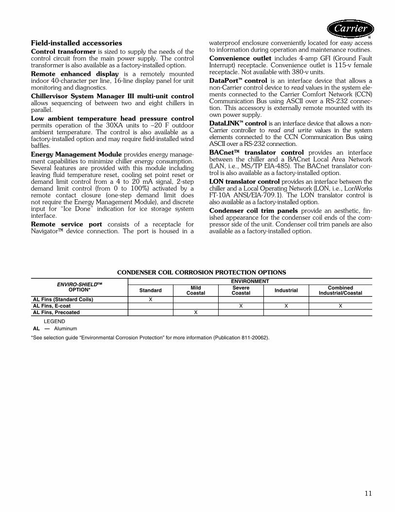
CONDENSER COIL CORROSION PROTECTION OPTIONS
LEGEND
*See selection guide “Environmental Corrosion Protection” for more information (Publication 811-20062).
ENVIRO-SHIELD™OPTION*
ENVIRONMENT
Standard MildCoastal
SevereCoastal Industrial Combined
Industrial/CoastalAL Fins (Standard Coils) XAL Fins, E-coat X X XAL Fins, Precoated X
AL — Aluminum

12
Dimensions
Coo
ler
Tube
S
ervi
ce A
rea
Pip
ing
Ent
ranc
e
7/8"
kno
ckou
ts fo
r m
ain
pow
er e
ntry
(7
.48"
[190
mm
] hol
e sp
acin
g)C
ontr
ol B
ox A
ll V
olta
ges
88.0
4[2
236]
68.0
6[1
729]
43.8
5[1
114]
23.7
2[6
02]
141.
22
[358
7]
121.
17 [3
078]
109.
0 [2
769]
65.7
3[1
670]
5.83
[148
]
5" V
icta
ulic
Ent
erin
g W
ater
5" V
icta
ulic
Lea
ving
Wat
er
90.5
5[2
300]
19.0
6[4
84]
10.8
[274
]
88.
04
[223
6]68.0
6 [1
729]
EN
D V
IEW
TO
P V
IEW
30X
A080
NO
TE
S:
1.U
nitm
usth
ave
clea
ranc
esas
follo
ws:
Top
—D
ono
tres
tric
tS
ides
and
End
s—
6ft
from
solid
surf
ace.
2.Te
mpe
ratu
rere
lief
devi
ces
are
loca
ted
onliq
uid
line
and
econ
o-m
izer
asse
mbl
ies
and
have
1 /4-
in.f
lare
conn
ectio
n.3.
3 /8-
in.
NP
Tve
nts
and
drai
nslo
cate
din
each
cool
erhe
adat
each
end
ofco
oler
.4.
Dra
win
gde
pict
sun
itw
ithsi
ngle
-poi
ntpo
wer
and
stan
dard
two-
pass
cool
er.
Ref
erto
the
Pac
kage
dC
hille
rB
uild
erpr
ogra
mfo
rot
her
conf
igur
atio
ns.
5.D
imen
sion
sar
esh
own
inin
ches
;di
men
sion
sin
brac
kets
are
inm
illim
eter
s.

13
Con
trol
po
wer
ent
ry
Con
trol
Box
All
Vol
tage
s
7/8"
kno
ckou
ts fo
r m
ain
pow
er e
ntry
(7
.48"
[190
mm
] hol
e sp
acin
g)O
ptio
nal N
on-f
used
D
isco
nnec
t Han
dle
90.5
5[2
300]
47.6
5[1
210]
41.1
[104
4]
88.0
4[2
236]
23.
72
[602
]
3/4
NP
T R
elie
fC
onn.
Fem
ale
5" V
icta
ulic
E
nter
ing
Wat
er
5" V
icta
ulic
Le
avin
g W
ater
Coo
ler
Ven
t3/
8 N
PT
Coo
ler
Dra
in3/
8 N
PT M
ount
ing
Hol
es
Rig
ging
Hol
es(S
ee D
etai
l A)
Con
trol
Box
All
Vol
tage
s
90.5
5[2
300]
19.0
6[4
84]
10.8
[274
]
141.
22
[358
7]
121.
17
[307
8]
109.
03
[276
9]16
.1 [4
09]
0-3
15/1
6
0-7
7/8
[200
]
CO
NTA
CT
SU
RFA
CE
SC
ALE
4”
= 1
”
TY
PIC
AL
4 P
LAC
ES
DE
TAIL
"A
"
MO
UN
TIN
G P
LAT
E[1
00]
MO
UN
TIN
G H
OLE
.875
DIA
.[022
]
MO
UN
TIN
G P
LAT
E1.
50 D
IA. [
038]
RIG
GIN
G H
OLE
[127
]0-
5
[33]
0-1
5/16
0-1
3/4
[44]
LEF
T E
ND
VIE
WS
IDE
VIE
W
30X
A080 (co
nt)
NO
TE
S:
1.U
nitm
usth
ave
clea
ranc
esas
follo
ws:
Top
—D
ono
tres
tric
tS
ides
and
End
s—
6ft
from
solid
surf
ace.
2.Te
mpe
ratu
rere
lief
devi
ces
are
loca
ted
onliq
uid
line
and
econ
omiz
eras
sem
blie
san
dha
ve1 /
4-in
.fla
reco
nnec
tion.
3.3 /
8-in
.N
PT
vent
san
ddr
ains
loca
ted
inea
chco
oler
head
atea
chen
dof
cool
er.
4.D
raw
ing
depi
cts
unit
with
sing
le-p
oint
pow
eran
dst
anda
rdtw
o-pa
ssco
oler
.R
efer
toth
eP
acka
ged
Chi
ller
Bui
lder
pro-
gram
for
othe
rco
nfig
urat
ions
.5.
Dim
ensi
ons
are
show
nin
inch
es;
dim
ensi
ons
inbr
acke
tsar
ein
mill
imet
ers.

14
Dimensions (cont)
5" V
icta
ulic
Le
avin
g W
ater
5" V
icta
ulic
E
nter
ing
Wat
er
90.5
5[2
300]
19.0
6[4
84]
10.8
[274
]
88.0
4[2
236]
68.0
6[1
729]
Coo
ler
Tube
S
ervi
ce A
rea
Pip
ing
Ent
ranc
e
7/8"
kno
ckou
ts fo
r m
ain
pow
er e
ntry
(7
.48"
[190
mm
] hol
e sp
acin
g)
Con
trol
Box
All
Vol
tage
s
88.0
4[2
236]
68.0
6[1
729]
188.
2 [4
780]
120.
85
[307
0]
109.
0 [2
769]
5.51
[140
]
23.7
2[6
02]
B
A
EN
D V
IEW
TO
P V
IEW
30X
A090-1
20
NO
TE
S:
1.U
nitm
usth
ave
clea
ranc
esas
follo
ws:
Top
—D
ono
tres
tric
tS
ides
and
End
s—
6ft
from
solid
surf
ace.
2.Te
mpe
ratu
rere
lief
devi
ces
are
loca
ted
onliq
uid
line
and
econ
o-m
izer
asse
mbl
ies
and
have
1 /4-
in.f
lare
conn
ectio
n.3.
3 /8-
in.
NP
Tve
nts
and
drai
nslo
cate
din
each
cool
erhe
adat
each
end
ofco
oler
.4.
Dra
win
gde
pict
sun
itw
ithsi
ngle
-poi
ntpo
wer
and
stan
dard
two-
pass
cool
er.
Ref
erto
the
Pac
kage
dC
hille
rB
uild
erpr
ogra
mfo
rot
her
conf
igur
atio
ns.
5.D
imen
sion
sar
esh
own
inin
ches
;di
men
sion
sin
brac
kets
are
inm
illim
eter
s.
30X
AU
NIT
AB
090
44.1
1(1
120)
86.9
3(2
208)
100
44.1
1(1
120)
87.2
2(2
215)
110
44.1
1(1
120)
87.6
2(2
226)
120
44.1
1(1
120)
87.1
2(2
213)

15
Con
trol
po
wer
ent
ry
7/8"
kno
ckou
ts fo
r m
ain
pow
er e
ntry
(7
.48"
[190
mm
] hol
e sp
acin
g)
Con
trol
Box
A
ll V
olta
ges
Opt
iona
l Non
-fus
ed
Dis
conn
ect H
andl
e
90.5
5[2
300]
47.6
5[1
210]
41.1
[104
4]
88.0
4[2
236]
23.7
2[6
02]
3/4
NP
T R
elie
f Con
n. F
emal
e
5" V
icta
ulic
E
nter
ing
Wat
er
5" V
icta
ulic
Le
avin
g W
ater
Coo
ler
Ven
t3/
8 N
PT
Coo
ler
Dra
in3/
8 N
PT
Mou
ntin
g H
oles
R
iggi
ng H
oles
(See
Det
ail A
)
Con
trol
Box
All
Vol
tage
s
90.5
5[2
300]
19.0
6[4
84]
10.8
[274
]
188.
2 [4
780]
120.
85
[307
0]
78.0
2 [1
982]
78.0
2 [1
982]
16.1
[409
]
LE
FT
EN
D V
IEW
SID
E V
IEW
0-3
15/1
6
0-7
7/8
[200
]
CO
NTA
CT
SU
RFA
CE
SC
ALE
4”
= 1
”
TY
PIC
AL
4 P
LAC
ES
DE
TAIL
"A
"
MO
UN
TIN
G P
LAT
E[1
00]
MO
UN
TIN
G H
OLE
.875
DIA
.[022
]
MO
UN
TIN
G P
LAT
E1.
50 D
IA. [
038]
RIG
GIN
G H
OLE
[127
]0-
5
[33]
0-1
5/16
0-1
3/4
[44]
30X
A090-1
20 (co
nt)
NO
TE
S:
1.U
nitm
usth
ave
clea
ranc
esas
follo
ws:
Top
—D
ono
tres
tric
tS
ides
and
End
s—
6ft
from
solid
surf
ace.
2.Te
mpe
ratu
rere
lief
devi
ces
are
loca
ted
onliq
uid
line
and
econ
o-m
izer
asse
mbl
ies
and
have
1 /4-
in.f
lare
conn
ectio
n.3.
3 /8-
in.
NP
Tve
nts
and
drai
nslo
cate
din
each
cool
erhe
adat
each
end
ofco
oler
.4.
Dra
win
gde
pict
sun
itw
ithsi
ngle
-poi
ntpo
wer
and
stan
dard
two-
pass
cool
er.
Ref
erto
the
Pac
kage
dC
hille
rB
uild
erpr
ogra
mfo
rot
her
conf
igur
atio
ns.
5.D
imen
sion
sar
esh
own
inin
ches
;di
men
sion
sin
brac
kets
are
inm
illim
eter
s.
30X
AU
NIT
AB
090
44.1
1(1
120)
86.9
3(2
208)
100
44.1
1(1
120)
87.2
2(2
215)
110
44.1
1(1
120)
87.6
2(2
226)
120
44.1
1(1
120)
87.1
2(2
213)

16
Dimensions (cont)
Non
-fus
ed
Dis
conn
ect H
andl
e
Con
trol
Box
(200
/230
V o
nly)
Con
trol
pow
er e
ntry
Con
trol
Box
(a
ll vo
ltage
s ex
cept
200
/230
V)
7/8"
kno
ckou
ts fo
r m
ain
pow
er e
ntry
(5
.55"
[141
mm
] hol
e sp
acin
g)
90.5
5[2
300]
28.8
1[7
32]
23.6
2[6
00]
235.
24[5
975]
111.
58[2
834]
5" V
icta
ulic
E
nter
ing
Wat
er
5" V
icta
ulic
Le
avin
g W
ater
Con
trol
Box
(3
80, 4
60, 5
75V
onl
y)
90.5
5[2
300]
21.2
8[5
41]
10.5
8[2
69]
88.0
4[2
236]69
.14
[175
6]
Coo
ler
Tube
S
ervi
ce A
rea
Pip
ing
Ent
ranc
e
Con
trol
Box
(3
80,4
60,5
75V
onl
y)C
ontr
ol B
ox(2
00/2
30V
onl
y)
88.0
4[2
236]
69.1
4[1
756]
A
6.79
[172
]
235.
24[5
975]
121.
49[3
086]
109.
0[2
769]
5.84
[148
]
B
EN
D V
IEW
TO
P V
IEW
BA
CK
VIE
W
30X
A140,1
60
NO
TE
S:
1.U
nitm
usth
ave
clea
ranc
esas
follo
ws:
Top
—D
ono
tres
tric
tS
ides
and
End
s—
6ft
from
solid
surf
ace.
2.Te
mpe
ratu
rere
lief
devi
ces
are
loca
ted
onliq
uid
line
and
econ
o-m
izer
asse
mbl
ies
and
have
1 /4-
in.f
lare
conn
ectio
n.3.
3 /8-
in.
NP
Tve
nts
and
drai
nslo
cate
din
each
cool
erhe
adat
each
end
ofco
oler
.4.
Dra
win
gde
pict
sun
itw
ithsi
ngle
-poi
ntpo
wer
and
stan
dard
two-
pass
cool
er.
Ref
erto
the
Pac
kage
dC
hille
rB
uild
erpr
ogra
mfo
rot
her
conf
igur
atio
ns.
5.D
imen
sion
sar
esh
own
inin
ches
;di
men
sion
sin
brac
kets
are
inm
illim
eter
s.
30X
AU
NIT
AB
140
44.6
3(1
134)
115.
88(2
943)
160
44.6
1(1
133)
115.
64(2
937)

17
Con
trol
Box
(2
00/2
30V
onl
y)
Opt
iona
l Non
-fus
ed
Dis
conn
ect H
andl
e
Con
trol
P
ower
Ent
ry
7/8"
kno
ckou
ts fo
rm
ain
pow
er e
ntry
(5
.55"
[141
mm
] ho
le s
paci
ng)
Con
trol
Box
(3
80,4
60,5
75v
only
)
90.5
5[2
300]
47.6
5[1
210]
41.1
[104
4]
88.0
4[2
236]
6.79
[172
]
3/4
NP
T R
elie
f Con
n. F
emal
e
5" V
icta
ulic
Ent
erin
g W
ater
5" V
icta
ulic
Lea
ving
Wat
er
Coo
ler
Dra
in3/
8 N
PT
Coo
ler
Ven
t3/
8 N
PT
Mou
ntin
g H
oles
R
iggi
ng H
oles
(See
Det
ail A
)
Con
trol
Box
(2
00/2
30V
onl
y)
90.5
5[2
300]
21.2
8[5
41]
10.5
8[2
69]
235.
24[5
975]
121.
49[3
086]
109.
03[2
769]
58.0
8[1
475]
33.9
6[8
63]
16.1
[409
]
LEF
T E
ND
VIE
WS
IDE
VIE
W
0-3
15/1
6
0-7
7/8
[200
]
CO
NTA
CT
SU
RFA
CE
SC
ALE
4”
= 1
”
TY
PIC
AL
4 P
LAC
ES
DE
TAIL
"A
"
MO
UN
TIN
G P
LAT
E[1
00]
MO
UN
TIN
G H
OLE
.875
DIA
.[022
]
MO
UN
TIN
G P
LAT
E1.
50 D
IA. [
038]
RIG
GIN
G H
OLE
[127
]0-
5
[33]
0-1
5/16
0-1
3/4
[44]
30X
A140,1
60 (co
nt)
NO
TE
S:
1.U
nitm
usth
ave
clea
ranc
esas
follo
ws:
Top
—D
ono
tres
tric
tS
ides
and
End
s—
6ft
from
solid
surf
ace.
2.Te
mpe
ratu
rere
lief
devi
ces
are
loca
ted
onliq
uid
line
and
econ
o-m
izer
asse
mbl
ies
and
have
1 /4-
in.f
lare
conn
ectio
n.3.
3 /8-
in.
NP
Tve
nts
and
drai
nslo
cate
din
each
cool
erhe
adat
each
end
ofco
oler
.4.
Dra
win
gde
pict
sun
itw
ithsi
ngle
-poi
ntpo
wer
and
stan
dard
two-
pass
cool
er.
Ref
erto
the
Pac
kage
dC
hille
rB
uild
erpr
ogra
mfo
rot
her
conf
igur
atio
ns.
5.D
imen
sion
sar
esh
own
inin
ches
;di
men
sion
sin
brac
kets
are
inm
illim
eter
s.
30X
AU
NIT
AB
140
44.6
3(1
134)
115.
88(2
943)
160
44.6
1(1
133)
115.
64(2
937)

18
Dimensions (cont)
Opt
iona
l Non
-fus
ed
Dis
conn
ect H
andl
e
Con
trol
pow
er e
ntry
7/8"
kno
ckou
ts fo
r m
ain
pow
er e
ntry
(5
.55"
[141
mm
] hol
e sp
acin
g)
Con
trol
Box
(3
80,4
60,5
75v
only
)
Con
trol
Box
(200
/230
V o
nly)
90.5
5[2
300]
28.8
1[7
32]
23.6
2[6
00]
282.
2[7
168]
158.
6 [4
028]
6" V
icta
ulic
E
nter
ing
Wat
er
6" V
icta
ulic
Le
avin
g W
ater
Con
trol
Box
(3
80,4
60,5
75V
onl
y)
90.5
5[2
300]
22.4
8[5
71]
11.3
[287
]
88.0
4[2
236]70
.16
[178
2]
Coo
ler
Tube
S
ervi
ce A
rea
Pip
ing
Ent
ranc
e
Con
trol
Box
(200
/230
V o
nly)
Con
trol
Box
(3
80,4
60,5
75V
onl
y)
88.0
4[2
236]
70.1
6[1
782]
A
6.79
[172
]
282.
22[7
168]
177.
65[4
512]
109.
39[2
779]
61.6
[156
5]
B
BA
CK
VIE
W
EN
D V
IEW
TO
P V
IEW
30X
A180, 200
NO
TE
S:
1.U
nitm
usth
ave
clea
ranc
esas
follo
ws:
Top
—D
ono
tres
tric
tS
ides
and
End
s—
6ft
from
solid
surf
ace.
2.Te
mpe
ratu
rere
lief
devi
ces
are
loca
ted
onliq
-ui
dlin
ean
dec
onom
izer
asse
mbl
ies
and
have
1 /4-
in.f
lare
conn
ectio
n.3.
3 /8-
in.
NP
Tve
nts
and
drai
nslo
cate
din
each
cool
erhe
adat
each
end
ofco
oler
.4.
Dra
win
gde
pict
sun
itw
ithsi
ngle
-poi
ntpo
wer
and
stan
dard
two-
pass
cool
er.
Ref
erto
the
Pac
kage
dC
hille
rB
uild
erpr
ogra
mfo
rot
her
conf
igur
atio
ns.
5.D
imen
sion
sar
esh
own
inin
ches
;di
men
sion
sin
brac
kets
are
inm
illim
eter
s.
30X
AU
NIT
AB
180
46.1
2(1
171)
143.
04(3
633)
200
46.1
5(1
172)
142.
97(3
631)

19
Opt
iona
l Non
-fus
ed
Dis
conn
ect H
andl
e
Con
trol
P
ower
Ent
ry
7/8"
kno
ckou
ts fo
r m
ain
pow
er e
ntry
(5
.55"
[141
mm
] ho
le s
paci
ng)
Con
trol
Box
(3
80,4
60,
575v
onl
y)
Con
trol
Box
(2
00/2
30V
onl
y)
90.5
5[2
300]
47.6
5[1
210]
41.1
[104
4]
88.0
4[2
236]
6.79
[172
]
LEF
T E
ND
VIE
WS
IDE
VIE
W
3/4
NP
T R
elie
f C
onn.
Fem
ale
6"
Vic
taul
ic E
nter
ing
Wat
er
6" V
icta
ulic
Lea
ving
Wat
erC
oole
r V
ent
3/8
NP
T
Coo
ler
Dra
in3/
8 N
PT
Mou
ntin
g H
oles
Rig
ging
Hol
es(S
ee D
etai
l A)
90.5
5[2
300]
22.4
8[5
71]
11.3
[287
]
282.
22[7
168]
177.
65[4
512]
78.0
2[1
982]
78.0
2[1
982]
58.0
8[1
475]
33.9
7[8
63]
18.7
[489
]
0-3
15/1
6
0-7
7/8
[200
]
CO
NTA
CT
SU
RFA
CE
SC
ALE
4”
= 1
”
TY
PIC
AL
4 P
LAC
ES
DE
TAIL
"A
"
MO
UN
TIN
G P
LAT
E[1
00]
MO
UN
TIN
G H
OLE
.875
DIA
.[022
]
MO
UN
TIN
G P
LAT
E1.
50 D
IA. [
038]
RIG
GIN
G H
OLE
[127
]0-
5
[33]
0-1
5/16
0-1
3/4
[44]
30X
A180, 200 (co
nt)
NO
TE
S:
1.U
nitm
usth
ave
clea
ranc
esas
follo
ws:
Top
—D
ono
tres
tric
tS
ides
and
End
s—
6ft
from
solid
surf
ace.
2.Te
mpe
ratu
rere
lief
devi
ces
are
loca
ted
onliq
uid
line
and
econ
o-m
izer
asse
mbl
ies
and
have
1 /4-
in.f
lare
conn
ectio
n.3.
3 /8-
in.
NP
Tve
nts
and
drai
nslo
cate
din
each
cool
erhe
adat
each
end
ofco
oler
.4.
Dra
win
gde
pict
sun
itw
ithsi
ngle
-poi
ntpo
wer
and
stan
dard
two-
pass
cool
er.
Ref
erto
the
Pac
kage
dC
hille
rB
uild
erpr
ogra
mfo
rot
her
conf
igur
atio
ns.
5.D
imen
sion
sar
esh
own
inin
ches
;di
men
sion
sin
brac
kets
are
inm
illim
eter
s.
30X
AU
NIT
AB
180
46.1
2(1
171)
143.
04(3
633)
200
46.1
5(1
172)
142.
97(3
631)

20
Dimensions (cont)
Opt
iona
l Non
-fus
ed
Dis
conn
ect H
andl
e
Con
trol
Pow
er E
ntry
7/8"
kno
ckou
ts fo
r m
ain
pow
er e
ntry
(5
.55"
[141
mm
] hol
e sp
acin
g)C
ontr
ol B
ox(2
00/2
30V
onl
y)
Con
trol
Box
(380
,460
,575
V o
nly)
(380
,460
,575
V o
nly)
90.5
5[2
300]
28.8
1[7
32]
28.8
1[7
32]
23.6
2[6
00]
329.
26 [8
363]
205.
6 [5
222]
140.
14 [3
560]
6" V
icta
ulic
E
nter
ing
Wat
er
6" V
icta
ulic
Le
avin
g W
ater
Con
trol
Box
es
90.5
5[2
300]
22.4
8[5
71]
11.3
[287
]
88.0
4[2
236]70
.16
[178
2]
Coo
ler
Tube
S
ervi
ce A
rea
Pip
ing
Ent
ranc
e
Con
trol
Box
(200
/230
V o
nly)
Con
trol
Box
88.0
4[2
236]
70.1
6[1
782]
A
329.
26 [8
363]
224.
65 [5
706]
B10
8.6
[275
8]
BA
CK
VIE
W
TO
P V
IEW
EN
D V
IEW
30X
A220, 240
NO
TE
S:
1.U
nitm
usth
ave
clea
ranc
esas
follo
ws:
Top
—D
ono
tres
tric
tS
ides
and
End
s—
6ft
from
solid
surf
ace.
2.Te
mpe
ratu
rere
lief
devi
ces
are
loca
ted
onliq
-ui
dlin
ean
dec
onom
izer
asse
mbl
ies
and
have
1 /4-
in.f
lare
conn
ectio
n.3.
3 /8-
in.
NP
Tve
nts
and
drai
nslo
cate
din
each
cool
erhe
adat
each
end
ofco
oler
.4.
Dra
win
gde
pict
sun
itw
ithsi
ngle
-poi
ntpo
wer
and
stan
dard
two-
pass
cool
er.
Ref
erto
the
Pac
kage
dC
hille
rB
uild
erpr
ogra
mfo
rot
her
conf
igur
atio
ns.
5.D
imen
sion
sar
esh
own
inin
ches
;di
men
sion
sin
brac
kets
are
inm
illim
eter
s.
30X
AU
NIT
AB
220
46.1
7(1
173)
171.
42(4
354)
240
46.2
3(1
174)
170.
83(4
339)

21
Con
trol
B
oxes
90.5
5[2
300]
88.0
4 [2
236]
3/4
NP
T R
elie
f Con
n. F
emal
e
6" V
icta
ulic
Ent
erin
g W
ater
6" V
icta
ulic
Lea
ving
Wat
erC
oole
r V
ent
3/8
NP
T
Coo
ler
Dra
in3/
8 N
PT
Mou
ntin
g H
oles
Rig
ging
Hol
es(S
ee D
etai
l A)
90.5
5[2
300]
22.4
8[5
71]
11.3
[287
]
329.
26 [8
363]
224.
65 [5
706]
109.
03 [2
769]
58.0
8 [1
475]
58.0
8 [1
475]
33.9
7 [8
63]
33.9
6 [8
63]
18.0
7[4
59]
LEF
T E
ND
VIE
WS
IDE
VIE
W
0-3
15/1
6
0-7
7/8
[200
]
CO
NTA
CT
SU
RFA
CE
SC
ALE
4”
= 1
”
TY
PIC
AL
4 P
LAC
ES
DE
TAIL
"A
"
MO
UN
TIN
G P
LAT
E[1
00]
MO
UN
TIN
G H
OLE
.875
DIA
.[022
]
MO
UN
TIN
G P
LAT
E1.
50 D
IA. [
038]
RIG
GIN
G H
OLE
[127
]0-
5
[33]
0-1
5/16
0-1
3/4
[44]
30X
A220, 240 (co
nt)
NO
TE
S:
1.U
nitm
usth
ave
clea
ranc
esas
follo
ws:
Top
—D
ono
tres
tric
tS
ides
and
End
s—
6ft
from
solid
surf
ace.
2.Te
mpe
ratu
rere
lief
devi
ces
are
loca
ted
onliq
uid
line
and
econ
o-m
izer
asse
mbl
ies
and
have
1 /4-
in.f
lare
conn
ectio
n.3.
3 /8-
in.
NP
Tve
nts
and
drai
nslo
cate
din
each
cool
erhe
adat
each
end
ofco
oler
.4.
Dra
win
gde
pict
sun
itw
ithsi
ngle
-poi
ntpo
wer
and
stan
dard
two-
pass
cool
er.
Ref
erto
the
Pac
kage
dC
hille
rB
uild
erpr
ogra
mfo
rot
her
conf
igur
atio
ns.
5.D
imen
sion
sar
esh
own
inin
ches
;di
men
sion
sin
brac
kets
are
inm
illim
eter
s.
30X
AU
NIT
AB
220
46.1
7(1
173)
171.
42(4
354)
240
46.2
3(1
174)
170.
83(4
339)

22
Dimensions (cont)
6" V
icta
ulic
E
nter
ing
Wat
er
6" V
icta
ulic
Le
avin
g W
ater
Con
trol
Box
A
ll V
olta
ges
90.5
5[2
300]
23.6
3[6
00]
12.2
1[3
10]
88.0
4 [2
236]
71.0
6 [1
805]
Coo
ler
Tube
S
ervi
ce A
rea
Pip
ing
Ent
ranc
e
Con
trol
Box
All
Vol
tage
s
88.0
4[2
236]
71.0
6[1
805]
A
376.
2 [9
555]
304.
71 [7
740]
B18
8.35
[478
4]
Con
trol
Pow
er E
ntry
Opt
iona
l Non
-fus
ed
Dis
conn
ect H
andl
e
Con
trol
Box
All
Vol
tage
s
7/8"
kno
ckou
ts fo
r m
ain
pow
er e
ntry
(5
.55"
[141
mm
] hol
e sp
acin
g)
90.5
5[2
300]
28.8
1[7
32]
23.6
2[6
00]
376.
2 [9
555]
245.
52 [6
236]
EN
D V
IEW
TO
P V
IEW
BA
CK
VIE
W
30X
A260-3
00
NO
TE
S:
1.U
nit
mus
tha
vecl
eara
nces
asfo
llow
s:To
p—
Do
notr
estr
ict
Sid
esan
dE
nds
—6
ftfr
omso
lidsu
rface
.2.
Tem
pera
ture
relie
fde
vice
sar
elo
cate
don
liqui
dlin
ean
dec
ono-
miz
eras
sem
blie
san
dha
ve1 /
4-in
.fla
reco
nnec
tion.
3.3 /
8-in
.N
PT
vent
san
ddr
ains
loca
ted
inea
chco
oler
head
atea
chen
dof
cool
er.
4.D
raw
ing
depi
cts
unit
with
sing
le-
poin
tpo
wer
and
stan
dard
two-
pass
cool
er.
Ref
erto
the
Pac
k-ag
edC
hille
rB
uild
erpr
ogra
mfo
rot
her
conf
igur
atio
ns.
5.D
imen
sion
sar
esh
own
inin
ches
;di
men
sion
sin
brac
kets
are
inm
illim
eter
s.
30X
AU
NIT
AB
260
44.2
2(1
123)
216.
16(5
490)
280
44.3
0(1
125)
215.
86(5
483)
300
44.3
2(1
126)
216.
18(5
491)

23
3/4
NP
T R
elie
f Con
n. F
emal
e 6" V
icta
ulic
Ent
erin
g W
ater
6" V
icta
ulic
Lea
ving
Wat
erC
oole
r V
ent
3/8
NP
T
Coo
ler
Dra
in3/
8 N
PT
Mou
ntin
g H
oles
Rig
ging
Hol
es(S
ee D
etai
l A)
90.5
5[2
300]
23.6
3[6
00]
12.2
1[3
10]
376.
2 [9
555]
304.
71 [7
740]
78.0
2 [1
982]
78.0
2 [1
982]
78.0
2 [1
982]
78.0
2 [1
982]
31.9
6 [8
12]
16.1
[409
]
Con
trol
Box
A
ll V
olta
ges
90.5
5[2
300]
88.0
4 [2
236]
LEF
T E
ND
VIE
WS
IDE
VIE
W
0-3
15/1
6
0-7
7/8
[200
]
CO
NTA
CT
SU
RFA
CE
SC
ALE
4”
= 1
”
TY
PIC
AL
4 P
LAC
ES
DE
TAIL
"A
"
MO
UN
TIN
G P
LAT
E[1
00]
MO
UN
TIN
G H
OLE
.875
DIA
.[022
]
MO
UN
TIN
G P
LAT
E1.
50 D
IA. [
038]
RIG
GIN
G H
OLE
[127
]0-
5
[33]
0-1
5/16
0-1
3/4
[44]
30X
A260-3
00 (co
nt)
NO
TE
S:
1.U
nitm
usth
ave
clea
ranc
esas
follo
ws:
Top
—D
ono
tres
tric
tS
ides
and
End
s—
6ft
from
solid
surf
ace.
2.Te
mpe
ratu
rere
lief
devi
ces
are
loca
ted
onliq
uid
line
and
econ
o-m
izer
asse
mbl
ies
and
have
1 /4-
in.f
lare
conn
ectio
n.3.
3 /8-
in.
NP
Tve
nts
and
drai
nslo
cate
din
each
cool
erhe
adat
each
end
ofco
oler
.4.
Dra
win
gde
pict
sun
itw
ithsi
ngle
-poi
ntpo
wer
and
stan
dard
two-
pass
cool
er.
Ref
erto
the
Pac
kage
dC
hille
rB
uild
erpr
ogra
mfo
rot
her
conf
igur
atio
ns.
5.D
imen
sion
sar
esh
own
inin
ches
;di
men
sion
sin
brac
kets
are
inm
illim
eter
s.
30X
AU
NIT
AB
260
44.2
2(1
123)
216.
16(5
490)
280
44.3
0(1
125)
215.
86(5
483)
300
44.3
2(1
126)
216.
18(5
491)

24
Dimensions (cont)
Opt
iona
l Non
-fus
ed
Dis
conn
ect H
andl
e
Con
trol
pow
er e
ntry
Con
trol
Box
All
Vol
tage
s7/
8" k
nock
outs
for
mai
n po
wer
ent
ry
(5.5
5" [1
41 m
m] h
ole
spac
ing)
90.5
5[2
300]
28.8
1[7
32]
TO
P V
IEW
EN
D V
IEW
BA
CK
VIE
W
23.6
2[6
00]
423.
24 [1
0750
]
292.
56 [7
431]
Coo
ler
Tube
S
ervi
ce A
rea
Pip
ing
Ent
ranc
e
Con
trol
Box
All
Vol
tage
s
88.0
4[2
236]
71.0
6[1
805]
A
423.
24 [1
0750
]
349.
02 [8
865]
B23
2.66
[591
0]
6" V
icta
ulic
E
nter
ing
Wat
er
6" V
icta
ulic
Le
avin
g W
ater
Con
trol
Box
A
ll V
olta
ges
90.5
5[2
300]
23.6
3[6
00]
12.2
1[3
10]
88.0
4 [2
236]
71.0
6 [1
805]
30X
A325,3
50
NO
TE
S:
1.U
nitm
usth
ave
clea
ranc
esas
follo
ws:
Top
—D
ono
tres
tric
tS
ides
and
End
s—
6ft
from
solid
surf
ace.
2.Te
mpe
ratu
rere
lief
devi
ces
are
loca
ted
onliq
uid
line
and
econ
omiz
eras
sem
-bl
ies
and
have
1 /4-
in.f
lare
conn
ectio
n.3.
3 /8-
in.
NP
Tve
nts
and
drai
nslo
cate
din
each
cool
erhe
adat
each
end
ofco
oler
.4.
Dra
win
gde
pict
sun
itw
ithsi
ngle
-poi
ntpo
wer
and
stan
dard
two-
pass
cool
er.
Ref
erto
the
Pac
kage
dC
hille
rB
uild
erpr
ogra
mfo
rot
her
conf
igur
atio
ns.
5.D
imen
sion
sar
esh
own
inin
ches
;di
men
sion
sin
brac
kets
are
inm
illim
eter
s.
30X
AU
NIT
AB
325
42.9
2(1
090)
246.
16(6
252)
350
42.9
2(1
090)
246.
72(6
267)

25
Con
trol
Box
All
Vol
tage
s90
.55
[230
0]
88.0
4 [2
236]
3/4
NP
T R
elie
f Con
n. F
emal
e 6" V
icta
ulic
Ent
erin
g W
ater
6" V
icta
ulic
Lea
ving
Wat
erC
oole
r V
ent
3/8
NP
T
Coo
ler
Dra
in3/
8 N
PT
Mou
ntin
g H
oles
Rig
ging
Hol
es(S
ee D
etai
l A)
90.5
5[2
300]
23.6
3[6
00]
12.2
1[3
10]
423.
24
[107
50]
349.
02
[886
5]
109.
03[2
769]
78.0
2[1
982]
78.0
2[1
982]
58.0
8 [1
475]
33.9
7[8
63]
33.9
6 [8
63]
16.1
[4
09]
SID
E V
IEW
LE
FT
EN
D V
IEW
0-3
15/1
6
0-7
7/8
[200
]
CO
NTA
CT
SU
RFA
CE
SC
ALE
4”
= 1
”
TY
PIC
AL
4 P
LAC
ES
DE
TAIL
"A
"
MO
UN
TIN
G P
LAT
E[1
00]
MO
UN
TIN
G H
OLE
.875
DIA
.[022
]
MO
UN
TIN
G P
LAT
E1.
50 D
IA. [
038]
RIG
GIN
G H
OLE
[127
]0-
5
[33]
0-1
5/16
0-1
3/4
[44]
30X
A325,3
50 (co
nt)
NO
TE
S:
1.U
nitm
usth
ave
clea
ranc
esas
follo
ws:
Top
—D
ono
tres
tric
tS
ides
and
End
s—
6ft
from
solid
surf
ace.
2.Te
mpe
ratu
rere
lief
devi
ces
are
loca
ted
onliq
uid
line
and
econ
o-m
izer
asse
mbl
ies
and
have
1 /4-
in.f
lare
conn
ectio
n.3.
3 /8-
in.
NP
Tve
nts
and
drai
nslo
cate
din
each
cool
erhe
adat
each
end
ofco
oler
.4.
Dra
win
gde
pict
sun
itw
ithsi
ngle
-poi
ntpo
wer
and
stan
dard
two-
pass
cool
er.
Ref
erto
the
Pac
kage
dC
hille
rB
uild
erpr
ogra
mfo
rot
her
conf
igur
atio
ns.
5.D
imen
sion
sar
esh
own
inin
ches
;di
men
sion
sin
brac
kets
are
inm
illim
eter
s.
30X
AU
NIT
AB
325
42.9
2(1
090)
246.
16(6
252)
350
42.9
2(1
090)
246.
72(6
267)

26
Dimensions (cont)
Con
trol
pow
er e
ntry
Con
trol
pow
er e
ntry
Opt
iona
l Non
-fus
ed
Dis
conn
ect H
andl
es
Con
trol
Box
#2
7/8"
Kno
ckou
ts fo
r C
kt 1
pow
er
(5.5
5" b
etw
een
hole
s)
Con
trol
Box
#1
7/8"
Kno
ckou
ts fo
r C
kt 2
pow
er(5
.55"
bet
wee
n ho
les)
90.5
5[2
300]
28.8
1[7
32]
28.8
1[7
32]
23.6
2[6
00]
470.
22 [1
1944
]
331.
58 [8
422]
151.
5 [3
848]
8" V
icta
ulic
E
nter
ing
Wat
er
Con
trol
B
oxes
90.5
5[2
300]
17.9
2[4
55]
88.0
4 [2
236]
72.1
[183
1]
Coo
ler
Tube
S
ervi
ce A
rea
Pip
ing
Ent
ranc
e
Pip
ing
Ent
ranc
eC
ontr
ol B
ox #
1C
ontr
ol B
ox #
2
88.0
4[2
236]
72.1
[183
1]
70.0
2[1
779]
45.7
9[1
163]
470.
22 [1
1944
]
378.
95 [9
625]
240.
69 [6
114]
TO
P V
IEW
EN
D V
IEW
BA
CK
VIE
W
53.2
9 [1
354]
63.3
5 [1
609]
119.
07 [3
024]
30X
A400
NO
TE
S:
1.U
nitm
usth
ave
clea
ranc
esas
follo
ws:
Top
—D
ono
tres
tric
tS
ides
and
End
s—
6ft
from
solid
surf
ace.
2.Te
mpe
ratu
rere
lief
devi
ces
are
loca
ted
onliq
-ui
dlin
ean
dec
onom
izer
asse
mbl
ies
and
have
1 /4-
in.f
lare
conn
ectio
n.3.
3 /8-
in.
NP
Tve
nts
and
drai
nslo
cate
din
each
cool
erhe
adat
each
end
ofco
oler
.4.
Dra
win
gde
pict
sun
itw
ithdu
al-p
oint
pow
eran
dst
anda
rdon
e-pa
ssco
oler
.R
efer
toth
eP
acka
ged
Chi
ller
Bui
lder
prog
ram
for
othe
rco
nfig
urat
ions
.5.
Act
ualc
oole
rco
nsis
tsof
two
sepa
rate
cool
ers
pipe
din
serie
sat
the
fact
ory.
Pip
ing
may
besp
litfo
rrig
ging
.6.
Dim
ensi
ons
are
show
nin
inch
es;
dim
ensi
ons
inbr
acke
tsar
ein
mill
imet
ers.

27
8" V
icta
ulic
Lea
ving
Wat
er
Con
trol
B
oxes
90.5
5[2
300]
17.9
2[4
55]
88.0
4 [2
236]
70.0
2 [1
779]
3/4
NP
T R
elie
f Con
n. F
emal
e
8" V
icta
ulic
Ent
erin
g W
ater
8" V
icta
ulic
Lea
ving
Wat
er
Coo
ler
Ven
t 3/8
NP
Tlo
cate
d in
coo
ler
head
s
Coo
ler
Dra
in 3
/8 N
PT
loca
ted
in c
oole
r he
ads
Mou
ntin
g H
oles
Rig
ging
Hol
es(S
ee D
etai
l A)
90.5
5[2
300]
17.9
2[4
55]
17.9
2[4
55]
470.
22 [1
1944
]37
8.95
[962
5]53
.29
[135
4]
78.0
2 [1
982]
78.0
2 [1
982]
78.0
2 [1
982]
78.0
2 [1
982]
58.0
8 [1
475]
33.9
3[8
62]
31.9
6[8
12]
16.1
[4
09]
SID
E V
IEW
LE
FT
EN
D V
IEW
0-3
15/1
6
0-7
7/8
[200
]
CO
NTA
CT
SU
RFA
CE
SC
ALE
4”
= 1
”
TY
PIC
AL
4 P
LAC
ES
DE
TAIL
"A
"
MO
UN
TIN
G P
LAT
E[1
00]
MO
UN
TIN
G H
OLE
.875
DIA
.[022
]
MO
UN
TIN
G P
LAT
E1.
50 D
IA. [
038]
RIG
GIN
G H
OLE
[127
]0-
5
[33]
0-1
5/16
0-1
3/4
[44]
30X
A400 (co
nt)
NO
TE
S:
1.U
nitm
usth
ave
clea
ranc
esas
follo
ws:
Top
—D
ono
tres
tric
tS
ides
and
End
s—
6ft
from
solid
surf
ace.
2.Te
mpe
ratu
rere
lief
devi
ces
are
loca
ted
onliq
uid
line
and
econ
o-m
izer
asse
mbl
ies
and
have
1 /4-
in.f
lare
conn
ectio
n.3.
3 /8-
in.
NP
Tve
nts
and
drai
nslo
cate
din
each
cool
erhe
adat
each
end
ofco
oler
.4.
Dra
win
gde
pict
sun
itw
ithdu
al-p
oint
pow
eran
dst
anda
rdon
e-pa
ssco
oler
.R
efer
toth
eP
acka
ged
Chi
ller
Bui
lder
prog
ram
for
othe
rco
nfig
urat
ions
.5.
Act
ualc
oole
rco
nsis
tsof
two
sepa
rate
cool
ers
pipe
din
serie
sat
the
fact
ory.
Pip
ing
may
besp
litfo
rrig
ging
.6.
Dim
ensi
ons
are
show
nin
inch
es;
dim
ensi
ons
inbr
acke
tsar
ein
mill
imet
ers.

28
Dimensions (cont)
Non
-fus
ed D
isco
nnec
t Han
dles
Con
trol
pow
er e
ntry
Con
trol
pow
er e
ntry
7/8"
Kno
ckou
ts fo
r C
kt 1
pow
er
(5.5
5" b
etw
een
hole
s)7/
8" K
nock
outs
for
Ckt
2 p
ower
(5.5
5" b
etw
een
hole
s)
Con
trol
Box
#1
Con
trol
Box
#2
TO
P V
IEW
EN
D V
IEW
BA
CK
VIE
W
90.5
5[2
300]
28.8
1[7
32]
28.8
1[7
32]
23.6
2[6
00]
517.
26 [1
3138
]
378.
62 [9
617]
198.
54 [5
043]
Coo
ler
Tube
S
ervi
ce A
rea
Pip
ing
Ent
ranc
e
Pip
ing
Ent
ranc
e
Con
trol
Box
#2
Con
trol
Box
#1
88.0
4[2
236]
73.0
[185
4]71
.06
[180
5]
A
517.
26 [1
3138
]
426.
0 [1
0820
]B
129.
1 [3
279]
8" V
icta
ulic
Ent
erin
g W
ater
Con
trol
Box
es
90.5
5[2
300]
17.9
2[4
55]
88.0
4 [2
236]
73.0
[185
4]
83.6
2 [2
124]
93.6
8 [2
379]
30X
A450, 500
NO
TE
S:
1.U
nitm
usth
ave
clea
ranc
esas
follo
ws:
Top
—D
ono
tres
tric
tS
ides
and
End
s—
6ft
from
solid
surf
ace.
2.Te
mpe
ratu
rere
liefd
evic
esar
elo
cate
don
liqui
dlin
ean
dec
onom
izer
asse
m-
blie
san
dha
ve1 /
4-in
.fla
reco
nnec
tion.
3.3 /
8-in
.NP
Tve
nts
and
drai
nslo
cate
din
each
cool
erhe
adat
each
end
ofco
oler
.4.
Dra
win
gde
pict
sun
itw
ithdu
al-p
oint
pow
eran
dst
anda
rdon
e-pa
ssco
oler
.R
efer
toth
eP
acka
ged
Chi
ller
Bui
lder
prog
ram
for
othe
rco
nfig
urat
ions
.5.
Act
ualc
oole
rco
nsis
tsof
two
sepa
rate
cool
ers
pipe
din
serie
sat
the
fact
ory.
Pip
ing
may
besp
litfo
rrig
ging
.6.
Dim
ensi
ons
are
show
nin
inch
es;
dim
ensi
ons
inbr
acke
tsar
ein
mill
imet
ers.
30X
AU
NIT
AB
450
44.7
1(1
136)
264.
7(6
723)
500
44.7
8(1
137)
263.
99(6
705)

29
9" V
icta
ulic
Lea
ving
Wat
er
Con
trol
Box
es90
.55
[230
0]
17.9
2[4
55]
88.0
4 [2
236]
71.0
6 [1
805]
3/4
NP
T R
elie
f Con
n. F
emal
e
8" V
icta
ulic
Ent
erin
g W
ater
8" V
icta
ulic
Lea
ving
Wat
er
Coo
ler
Ven
t 3/8
NP
Tlo
cate
d in
coo
ler
head
s
Coo
ler
Dra
in 3
/8 N
PT
loca
ted
in c
oole
r he
ads
Mou
ntin
g H
oles
R
iggi
ng H
oles
(See
Det
ail A
)
90.5
5[2
300]
17.9
2[4
55]
17.9
2[4
55]
517.
26 [1
3138
]42
6.0
[108
20]
83.6
2 [2
124]
109.
03[2
769]
78.0
2[1
982]
78.0
2[1
982]
58.0
8[1
475]
58.0
8[1
475]
33.9
7[8
63]
33.9
7[8
63]
33.9
6[8
63]
18.0
7[4
59]
SID
E V
IEW
LE
FT
EN
D V
IEW
0-3
15/1
6
0-7
7/8
[200
]
CO
NTA
CT
SU
RFA
CE
SC
ALE
4”
= 1
”
TY
PIC
AL
4 P
LAC
ES
DE
TAIL
"A
"
MO
UN
TIN
G P
LAT
E[1
00]
MO
UN
TIN
G H
OLE
.875
DIA
.[022
]
MO
UN
TIN
G P
LAT
E1.
50 D
IA. [
038]
RIG
GIN
G H
OLE
[127
]0-
5
[33]
0-1
5/16
0-1
3/4
[44]
30X
A450, 500 (co
nt)
NO
TE
S:
1.U
nitm
usth
ave
clea
ranc
esas
follo
ws:
Top
—D
ono
tres
tric
tS
ides
and
End
s—
6ft
from
solid
surf
ace.
2.Te
mpe
ratu
rere
lief
devi
ces
are
loca
ted
onliq
uid
line
and
econ
o-m
izer
asse
mbl
ies
and
have
1 /4-
in.f
lare
conn
ectio
n.3.
3 /8-
in.
NP
Tve
nts
and
drai
nslo
cate
din
each
cool
erhe
adat
each
end
ofco
oler
.4.
Dra
win
gde
pict
sun
itw
ithdu
al-p
oint
pow
eran
dst
anda
rdon
e-pa
ssco
oler
.R
efer
toth
eP
acka
ged
Chi
ller
Bui
lder
prog
ram
for
othe
rco
nfig
urat
ions
.5.
Act
ualc
oole
rco
nsis
tsof
two
sepa
rate
cool
ers
pipe
din
serie
sat
the
fact
ory.
Pip
ing
may
besp
litfo
rrig
ging
.6.
Dim
ensi
ons
are
show
nin
inch
es;
dim
ensi
ons
inbr
acke
tsar
ein
mill
imet
ers.
30X
AU
NIT
AB
450
44.7
1(1
136)
264.
7(6
723)
500
44.7
8(1
137)
263.
99(6
705)
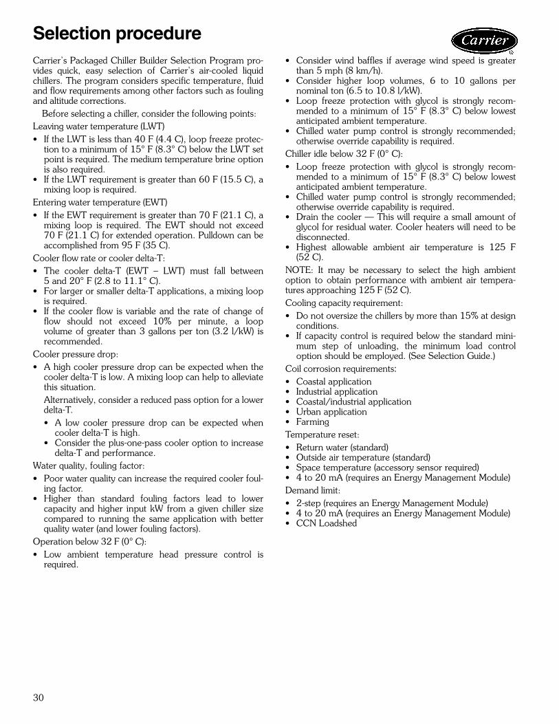
30
Carrier’s Packaged Chiller Builder Selection Program pro-vides quick, easy selection of Carrier’s air-cooled liquidchillers. The program considers specific temperature, fluidand flow requirements among other factors such as foulingand altitude corrections.
Before selecting a chiller, consider the following points:Leaving water temperature (LWT)• If the LWT is less than 40 F (4.4 C), loop freeze protec-
tion to a minimum of 15° F (8.3° C) below the LWT setpoint is required. The medium temperature brine optionis also required.
• If the LWT requirement is greater than 60 F (15.5 C), amixing loop is required.
Entering water temperature (EWT)• If the EWT requirement is greater than 70 F (21.1 C), a
mixing loop is required. The EWT should not exceed70 F (21.1 C) for extended operation. Pulldown can beaccomplished from 95 F (35 C).
Cooler flow rate or cooler delta-T:• The cooler delta-T (EWT – LWT) must fall between
5 and 20° F (2.8 to 11.1° C).• For larger or smaller delta-T applications, a mixing loop
is required.• If the cooler flow is variable and the rate of change of
flow should not exceed 10% per minute, a loopvolume of greater than 3 gallons per ton (3.2 l/kW) isrecommended.
Cooler pressure drop:• A high cooler pressure drop can be expected when the
cooler delta-T is low. A mixing loop can help to alleviatethis situation.Alternatively, consider a reduced pass option for a lowerdelta-T.• A low cooler pressure drop can be expected when
cooler delta-T is high.• Consider the plus-one-pass cooler option to increase
delta-T and performance.Water quality, fouling factor:• Poor water quality can increase the required cooler foul-
ing factor.• Higher than standard fouling factors lead to lower
capacity and higher input kW from a given chiller sizecompared to running the same application with betterquality water (and lower fouling factors).
Operation below 32 F (0° C):• Low ambient temperature head pressure control is
required.
• Consider wind baffles if average wind speed is greaterthan 5 mph (8 km/h).
• Consider higher loop volumes, 6 to 10 gallons pernominal ton (6.5 to 10.8 l/kW).
• Loop freeze protection with glycol is strongly recom-mended to a minimum of 15° F (8.3° C) below lowestanticipated ambient temperature.
• Chilled water pump control is strongly recommended;otherwise override capability is required.
Chiller idle below 32 F (0° C):• Loop freeze protection with glycol is strongly recom-
mended to a minimum of 15° F (8.3° C) below lowestanticipated ambient temperature.
• Chilled water pump control is strongly recommended;otherwise override capability is required.
• Drain the cooler — This will require a small amount ofglycol for residual water. Cooler heaters will need to bedisconnected.
• Highest allowable ambient air temperature is 125 F(52 C).
NOTE: It may be necessary to select the high ambientoption to obtain performance with ambient air tempera-tures approaching 125 F (52 C). Cooling capacity requirement:• Do not oversize the chillers by more than 15% at design
conditions.• If capacity control is required below the standard mini-
mum step of unloading, the minimum load controloption should be employed. (See Selection Guide.)
Coil corrosion requirements:• Coastal application• Industrial application• Coastal/industrial application• Urban application• FarmingTemperature reset:• Return water (standard)• Outside air temperature (standard)• Space temperature (accessory sensor required)• 4 to 20 mA (requires an Energy Management Module)Demand limit:• 2-step (requires an Energy Management Module)• 4 to 20 mA (requires an Energy Management Module)• CCN Loadshed
Selection procedure

31
To select a 30XA chiller, use the Packaged Chiller Builderprogram or follow one of the procedures below.
ENGLISHI Determine 30XA unit size and operating con-
ditions required to meet given capacity atgiven conditions. Given:Capacity . . . . . . . . . . . . . . . . . . . . . . . . . 106 TonsLeaving Chilled Water Temp (LCWT) . . . . . . . .42 FCooler Water Temp Rise . . . . . . . . . . . . . . . . 10° FCondenser Entering Air Temp . . . . . . . . . . . . .95 FFouling Factor (Cooler). . . .0.00010 (ft2 · hr · F/Btu)NOTE: For other than 10° F temperature rise, datacorrections must be made using the Packaged ChillerBuilder Program.
II From Cooling Capacities table on page 34 andpressure drop curves on page 33, determineoperating data for selected unit.Unit . . . . . . . . . . . . . . . . . . . . . . . . . . . .30XA120Capacity . . . . . . . . . . . . . . . . . . . . . . . . 107.5 tonsPower Input . . . . . . . . . . . . . . . . . . . . . .126.7 kWCooler Water Flow . . . . . . . . . . . . . . . . 257.0 gpmCooler Pressure Drop . . . . . . . . . . .12.0 ft of water
SII Determine 30XA unit size and operating con-
ditions required to meet given capacity atgiven conditions. Given:Capacity . . . . . . . . . . . . . . . . . . . . . . . . . . 450 kWLeaving Chilled Water Temp (LCWT) . . . . . . . . 6 CCooler Water Temp Rise . . . . . . . . . . . . . . . 5.6° CCondenser Entering Air Temp . . . . . . . . . . . . 35 CFouling Factor (Cooler). . . . . . . . .0176 (m2 · °C/W)NOTE: For other than 5.6 C temperature rise, datacorrections must be made using the Packaged ChillerBuilder Program.
II From Cooling Capacities table on page 36 andcooler pressure drop curves on page 33,determine operating data for selected unit.Unit . . . . . . . . . . . . . . . . . . . . . . . . . . . .30XA140Capacity . . . . . . . . . . . . . . . . . . . . . . . . .458.1 kWPower Input . . . . . . . . . . . . . . . . . . . . . .147.5 kWCooler Water Flow . . . . . . . . . . . . . . . . . . 19.7 l/sCooler Pressure Drop . . . . . . . . . . . . . . . 41.9 kPa

32
Selection procedure (cont)C
OR
RE
CT
ION
FA
CT
OR
0.90
0.95
1.00
1.10
1.15
1.201.20
1.25
1.35
1.30
1.40
1.45
1.50
1.55
1.60
1.65
% CONCENTRATION (BY WEIGHT) PROPYLENE GLYCOL
0 10 20 30 40 50+40
+20
0
-20
-40(F)
-40
-30
-20
-10
0
AM
BIE
NT
TE
MP
ER
AT
UR
E
(C)
1.05
SOLUTION CRYSTALLIZATION POINT
COOLER FLOW CORRECTION
COOLER P
RESSURE DRO
P CO
RREC
TIO
N
PROPYLENE GLYCOL PERFORMANCECORRECTION FACTORS AND SOLUTION
CRYSTALLIZATION POINTSCorrection factors apply to published chilled water
performance ratings from 40 to 60 F(4.4 to 15.6 C) LCWT.
ETHYLENE GLYCOL PERFORMANCECORRECTION FACTORS AND SOLUTION
CRYSTALLIZATION POINTSCorrection factors apply to published chilled water
performance ratings from 40 to 60 F(4.4 to 15.6 C) LCWT.
CO
RR
EC
TIO
N F
AC
TO
R
0.90
0.95
1.00
1.10
1.15
1.20
1.25
1.35
1.30
1.40
1.45
1.50
% CONCENTRATION (BY WEIGHT) PROPYLENE GLYCOL
0 10 20 30 40 50+40
+20
0
-20
-40(F)
-40
-30
-20
-10
0
AM
BIE
NT
TE
MP
ER
AT
UR
E
(C)
1.05
SOLUTION CRYSTALLIZATION POINT
CORRECTIONCAPACITY
COOLER FLOW CORRECTION
COOLER PRESSURE D
ROP CORRECTIO
N

33
Performance data
0
50(149.5)
0
Cooler Flow, GPM (l/kW)
Pre
ssu
re D
rop
, ft
wg
(kP
a)
080090,100 110 120
45(134.6)
40(119.6)
35(104.7)
30(89.7)
25(74.8)
20(59.8)
15(44.9)
10(29.9)
5(15)
100(107.6)
200(215.2)
300(322.8)
400(430.4)
500(538)
600(645.6)
00
Cooler Flow, GPM (l/kW)
Pre
ssu
re D
rop
,ft
wg
(kP
a)
140160
180200 220
240
60(179.4)
50(149.5)
40(119.6)
30(89.7)
20(59.8)
10(29.9)
200(215.2)
400(430.4)
600(645.6)
800(860.8)
1000(1076)
1200(1291.2)
1400(1506.4)
0
0
260 280300
325 350
400 450
500
Pre
ssu
re D
rop
, ft
wg
(kP
a)
60(179.4)
50(149.5)
40(119.6)
30(89.7)
20(59.8)
10(29.9)
500(538)
1000(1076)
1500(1614)
2000(2152)
2500(2690)
3000(3228)
Cooler Flow, GPM (l/kW)
COOLER PRESSURE DROP CURVES30XA080-120
30XA140-240
30XA260-500

34
30XA PACKAGED AIR-COOLED CHILLER RATINGS TABLE — ENGLISH
LEGEND NOTES:1. All ratings are in accordance with ARI (Air Conditioning and Refrigeration
Institute, U.S.A.) Standard 550/590-98, based on:a. A cooler water temperature rise of 10° F. For other than a 10° F temper-
ature rise, data corrections must be made using the Packaged ChillerBuilder Program.
b. A fouling factor of 0.00010 (ft2 · hr · F/Btu) in the cooler.c. Refrigerant 134a.
2. Ratings generated are based on standard ambient temperature (850 rpm)units.
LCWT (F)30XAUNITSIZE
CONDENSER ENTERING AIR TEMPERATURE (F)85 95 105 115
CapTons Power
CoolerFlow Rate
(gpm)
CapTons Power
CoolerFlow Rate
(gpm)
CapTons Power
CoolerFlow Rate
(gpm)
CapTons Power
CoolerFlow Rate
(gpm)
40
080 74.7 82.2 178.5 70.2 88.3 167.6 65.4 95.2 156.2 60.5 102.7 144.5090 82.4 84.9 196.7 79.2 92.7 189.1 75.8 101.6 181.1 72.3 111.3 172.6100 91.6 94.2 218.7 87.7 103.3 209.4 83.5 113.4 199.3 79.2 124.6 189.2110 100.4 103.5 239.8 96.2 113.7 229.7 91.6 124.9 218.7 86.8 137.6 207.3120 108.9 112.8 260.1 104.3 123.9 249.0 99.1 136.0 236.7 93.8 150.1 224.0140 129.4 131.6 309.1 124.5 144.7 297.3 119.2 159.2 284.7 113.6 175.0 271.3160 149.2 152.7 356.3 143.2 168.2 342.1 136.7 185.1 326.4 129.9 204.1 310.3180 166.5 170.1 397.5 160.3 186.8 382.9 153.8 205.1 367.3 146.9 225.2 350.8200 189.2 191.9 451.8 181.8 210.8 434.3 174.1 231.6 415.7 165.8 254.4 395.9220 205.4 211.6 490.5 197.3 232.8 471.1 188.5 256.3 450.2 179.1 282.6 427.8240 223.9 228.8 534.8 214.7 251.6 512.7 204.7 277.0 488.9 194.0 305.7 463.4260 244.1 248.0 583.1 234.9 272.7 561.1 225.2 300.2 537.8 214.9 330.8 513.1280 261.6 264.9 624.8 251.4 291.4 600.4 240.5 321.0 574.4 228.9 354.2 546.7300 282.2 284.0 674.0 271.1 311.4 647.6 259.1 342.9 618.9 246.3 378.2 588.3325 298.8 304.6 713.7 287.5 334.8 686.6 275.6 368.8 658.1 263.0 406.5 628.1350 318.1 325.0 759.7 305.8 357.2 730.4 292.8 393.5 699.4 279.1 434.1 666.6400 376.3 390.7 898.8 361.5 429.8 863.4 345.3 473.1 824.6 319.9 501.4 764.1450 417.8 444.9 997.7 401.3 490.0 958.4 383.9 540.3 916.8 324.5 539.7 774.9500 450.2 477.4 1075.3 431.9 525.7 1031.6 412.5 579.5 985.2 346.8 578.4 828.2
42
080 77.5 83.8 185.1 72.9 89.8 174.1 68.0 96.7 162.4 62.9 104.3 150.3090 85.1 85.9 203.4 81.8 93.8 195.5 78.3 102.7 187.2 74.6 112.6 178.4100 95.1 96.5 227.3 91.0 105.7 217.5 86.6 116.0 207.0 81.8 127.0 195.6110 103.7 105.8 247.9 99.3 116.2 237.4 94.5 127.6 225.9 89.5 140.5 213.9120 112.4 115.4 268.6 107.5 126.7 257.0 102.2 139.1 244.2 96.7 153.7 231.2140 133.8 133.5 319.8 128.7 146.7 307.6 123.2 161.3 294.5 117.4 177.3 280.5160 154.1 155.0 368.4 147.9 170.7 353.6 141.2 187.7 337.5 134.2 207.0 320.8180 172.2 172.7 411.6 165.9 189.5 396.5 159.1 208.0 380.3 152.0 228.2 363.1200 195.5 194.9 467.2 187.9 214.0 449.1 179.9 234.9 429.9 171.3 258.0 409.3220 213.0 214.4 509.1 204.5 235.8 488.8 195.5 259.5 467.1 185.7 286.1 443.9240 231.4 234.1 553.0 222.2 256.3 531.1 212.1 281.5 507.0 201.0 310.7 480.4260 252.5 252.3 603.6 243.0 277.2 580.7 232.8 305.0 556.4 222.1 335.9 530.8280 270.8 269.0 647.2 260.2 295.9 621.8 248.9 325.8 594.8 236.8 359.5 566.0300 290.9 290.9 695.1 279.4 318.8 667.7 267.3 350.0 638.9 251.6 379.0 601.4325 308.9 310.3 738.2 297.1 341.0 710.0 284.7 375.3 680.4 271.6 413.6 649.2350 327.7 333.5 783.2 315.2 365.8 753.4 302.1 401.9 722.0 285.7 440.3 682.8400 387.8 399.8 926.7 372.7 439.1 890.8 356.7 483.0 852.6 325.4 510.8 777.7450 431.0 454.1 1029.9 414.2 499.3 989.9 396.2 550.6 946.9 318.2 513.1 760.5500 463.6 489.7 1107.9 445.0 537.8 1063.6 425.3 591.8 1016.4 344.1 535.1 822.2
44
080 80.2 85.5 191.8 75.4 91.5 180.4 70.5 98.3 168.6 65.3 105.9 156.2090 88.0 87.2 210.4 84.4 95.0 201.9 80.9 103.9 193.3 77.0 113.8 184.2100 98.4 98.5 235.3 94.3 108.1 225.5 89.7 118.5 214.6 84.7 129.7 202.6110 107.0 108.2 255.9 102.4 118.6 244.9 97.5 130.3 233.1 92.3 143.6 220.8120 115.8 118.1 277.0 110.7 129.5 264.8 105.3 142.4 251.8 99.7 157.4 238.4140 138.2 135.3 330.5 132.9 148.7 317.8 127.2 163.5 304.3 121.2 179.6 289.8160 159.1 157.4 380.4 152.6 173.2 365.1 145.7 190.5 348.5 138.5 210.1 331.3180 177.8 175.1 425.2 171.3 192.1 409.6 164.4 210.9 393.1 157.1 231.3 375.6200 201.9 197.9 482.7 194.0 217.2 463.9 185.7 238.4 444.1 176.9 261.8 422.9220 219.9 218.8 525.9 211.6 239.5 505.9 202.4 262.8 484.0 192.4 289.7 460.1240 237.4 242.1 567.7 228.2 264.2 545.8 218.4 288.9 522.3 205.2 309.9 490.6260 260.9 256.5 623.9 251.0 281.8 600.3 240.5 310.0 575.2 229.4 341.2 548.6280 279.1 275.1 667.5 268.6 301.3 642.2 257.3 330.8 615.3 244.9 364.9 585.6300 299.4 297.8 715.9 287.5 326.4 687.5 275.0 358.4 657.7 256.8 379.5 614.1325 319.0 316.1 762.8 306.7 347.2 733.4 293.9 382.1 702.7 280.4 420.9 670.5350 337.3 342.0 806.6 324.3 375.0 775.4 310.6 411.9 742.8 289.6 444.7 692.5400 399.3 409.6 954.8 383.7 449.4 917.6 367.0 494.3 877.7 330.5 510.7 790.3450 443.5 465.5 1060.5 426.2 511.2 1019.3 408.0 562.4 975.6 331.3 522.0 792.3500 475.9 504.1 1138.1 457.0 552.7 1092.8 435.0 603.7 1040.1 349.8 552.1 836.5
Cap. — Cooling Capacity (Tons of Refrigeration)kW — Total PowerLCWT — Leaving Chilled Water Temperature
Performance data (cont)

35
30XA PACKAGED AIR-COOLED CHILLER RATINGS TABLE — ENGLISH (cont)
LEGEND NOTES:1. All ratings are in accordance with ARI (Air Conditioning and Refrigeration
Institute, U.S.A.) Standard 550/590-98, based on:a. A cooler water temperature rise of 10° F. For other than a 10° F temper-
ature rise, data corrections must be made using the Packaged ChillerBuilder Program.
b. A fouling factor of 0.00010 (ft2 · hr · F/Btu) in the cooler.c. Refrigerant 134a.
2. Ratings generated are based on standard ambient temperature (850 rpm)units.
3. Data for 30XA450, 500, LCWT 50, Condenser Entering Air Temperature115 F not available at time of printing.
LCWT (F)30XAUNITSIZE
CONDENSER ENTERING AIR TEMPERATURE (F)85 95 105 115
CapTons Power
CoolerFlow Rate
(gpm)
CapTons Power
CoolerFlow Rate
(gpm)
CapTons Power
CoolerFlow Rate
(gpm)
CapTons Power
CoolerFlow Rate
(gpm)
46
080 83.1 87.3 198.9 78.2 93.4 187.2 73.1 100.2 175.0 67.9 107.6 162.4090 91.4 89.0 218.6 87.6 96.8 209.6 83.6 105.6 200.1 79.5 115.3 190.2100 101.6 100.7 243.1 97.4 110.3 232.9 92.8 121.0 222.1 87.8 132.5 210.0110 110.4 110.6 264.1 105.6 121.2 252.7 100.6 133.2 240.8 95.2 146.7 227.9120 119.4 120.9 285.7 114.1 132.4 273.0 108.5 145.7 259.7 102.8 161.2 245.9140 142.8 137.3 341.6 137.3 150.8 328.5 131.4 165.7 314.5 125.2 182.0 299.6160 164.0 160.4 392.5 157.5 176.1 376.8 150.5 193.4 360.1 143.1 213.3 342.4180 183.6 177.7 439.4 176.9 194.9 423.3 169.7 213.8 406.2 162.2 234.4 388.1200 208.2 201.8 498.2 200.4 220.7 479.4 191.8 242.1 459.0 182.7 265.7 437.1220 226.2 224.9 541.2 217.8 245.3 521.2 208.7 268.9 499.4 198.9 295.1 475.8240 243.4 250.7 582.5 233.9 273.5 559.7 223.8 299.2 535.4 208.3 311.8 498.4260 269.0 261.9 643.7 259.0 286.9 619.8 248.5 315.0 594.6 237.1 346.7 567.3280 287.4 282.1 687.7 276.5 308.8 661.5 264.9 338.7 633.9 252.7 372.1 604.8300 307.4 306.8 735.6 295.6 335.0 707.3 282.8 367.1 676.7 262.0 379.9 627.0325 329.6 322.0 788.6 316.8 353.7 758.0 303.5 389.1 726.2 289.5 428.4 692.8350 347.2 351.1 830.8 333.7 384.9 798.5 319.6 422.6 764.6 293.6 449.1 702.4400 410.0 421.3 981.1 394.1 461.8 942.9 377.2 507.0 902.4 317.1 470.7 758.8450 455.8 477.0 1090.7 438.0 523.8 1047.9 415.2 569.0 993.4 336.1 516.9 804.2500 488.0 519.4 1167.6 468.6 568.7 1121.3 441.9 614.1 1057.5 360.7 557.0 863.1
48
080 86.1 89.1 206.1 81.0 95.3 194.0 75.8 102.2 181.4 70.3 102.0 168.4090 94.7 90.7 226.7 90.7 98.7 217.2 86.6 107.6 207.3 82.2 107.2 196.8100 104.8 102.9 250.8 100.4 112.7 240.3 95.6 123.5 229.0 90.5 124.9 216.6110 113.7 113.1 272.3 108.8 123.9 260.4 103.6 136.2 248.1 98.1 139.8 234.8120 123.0 123.8 294.5 117.4 135.5 281.1 111.7 149.3 267.5 105.8 154.9 253.3140 147.4 139.2 352.9 141.7 152.9 339.3 135.7 168.0 324.8 129.2 171.5 309.3160 168.4 164.9 403.3 161.8 180.2 387.4 154.9 197.4 370.8 147.4 204.1 353.0180 189.5 180.3 453.7 182.5 197.6 437.0 175.1 216.7 419.3 167.3 222.1 400.6200 213.7 208.0 511.4 205.7 226.6 492.5 197.4 247.1 472.6 188.3 254.6 450.9220 232.0 232.3 555.4 223.3 253.3 534.5 214.0 276.8 512.3 202.2 277.6 484.0240 249.4 259.4 597.1 239.4 283.1 573.3 228.8 309.7 547.8 208.8 288.8 499.8260 277.0 268.2 663.2 266.6 293.6 638.4 255.7 321.8 612.4 244.3 333.8 584.9280 295.7 289.3 708.0 284.4 316.5 680.8 272.4 347.1 652.1 257.7 352.3 617.0300 315.1 317.4 754.3 302.7 346.4 724.7 287.7 370.2 688.9 266.5 360.8 638.2325 339.9 328.9 813.8 327.0 360.3 783.0 313.2 396.1 749.9 298.7 412.9 715.2350 356.9 361.1 854.4 343.2 395.0 821.6 328.4 433.7 786.2 287.2 398.2 687.5400 420.9 433.4 1007.7 404.4 474.8 968.0 386.8 521.4 925.9 325.8 473.9 780.1450 468.1 490.3 1120.6 450.0 537.3 1077.3 422.6 575.7 1011.6 349.1 525.5 835.8500 499.5 537.6 1195.8 479.4 588.1 1147.7 448.1 626.1 1072.8 361.9 546.2 866.3
50
080 89.0 91.1 213.3 83.9 97.3 200.9 78.5 104.3 188.0 72.9 104.2 174.6090 97.8 92.4 234.4 93.9 100.6 224.9 89.6 109.7 214.7 85.1 109.5 203.7100 108.0 105.0 258.6 103.4 115.0 247.8 98.5 126.0 236.0 93.2 127.6 223.2110 117.1 115.6 280.5 112.0 126.6 268.2 106.7 139.3 255.5 101.0 143.2 241.8120 126.6 126.6 303.3 120.8 138.6 289.4 115.0 153.1 275.6 108.9 159.1 260.9140 152.1 141.2 364.3 146.2 155.0 350.1 140.0 170.2 335.3 133.3 173.9 319.2160 172.8 169.5 413.8 165.9 185.2 397.4 158.8 202.8 380.4 151.2 209.7 362.3180 195.4 182.9 468.1 188.2 200.4 450.8 180.6 219.6 432.6 172.6 225.2 413.4200 219.0 214.3 524.7 210.8 233.4 505.0 202.2 254.3 484.4 193.0 262.0 462.4220 237.7 239.9 569.3 228.7 261.6 547.7 219.1 285.7 524.8 210.4 291.5 504.0240 255.2 268.5 611.4 244.9 293.2 586.6 232.0 311.9 555.8 218.3 301.7 523.0260 284.2 276.2 680.8 273.8 301.5 655.9 262.9 329.5 629.8 252.9 336.9 605.9280 303.1 298.5 726.1 291.7 325.8 698.6 279.6 356.4 669.8 268.8 364.5 643.9300 322.7 328.4 772.9 309.8 358.3 742.1 292.3 373.8 700.2 278.5 373.5 667.0325 348.9 338.6 835.7 335.9 370.0 804.6 322.4 404.9 772.3 310.1 415.2 742.7350 365.7 372.7 876.1 351.6 407.4 842.2 334.6 442.8 801.5 312.8 440.6 749.4400 430.9 447.6 1032.1 414.1 489.6 991.8 394.3 527.7 944.5 330.8 470.4 792.3450 479.6 505.2 1148.8 460.7 553.5 1103.6 419.6 548.9 1005.2 353.1 519.1 845.8500 510.6 556.2 1223.1 489.8 608.3 1173.1 445.5 601.1 1067.2 — — —
Cap. — Cooling Capacity (Tons of Refrigeration)kW — Total PowerLCWT — Leaving Chilled Water Temperature

36
30XA PACKAGED AIR-COOLED CHILLER RATINGS TABLE — SI
LEGEND NOTES:1. All ratings are in accordance with ARI (Air Conditioning and Refrigeration
Institute, U.S.A.) Standard 550/590-98, based on:a. A cooler water temperature rise of 5.6° C. For other than a 5.6° C tem-
perature rise, data corrections must be made using the Packaged ChillerBuilder Program.
b. A fouling factor of 0.00018 (m2 · °C/W) in the cooler.c. Refrigerant 134a.
2. Ratings generated are based on standard ambient temperature (850 rpm)units.
LCWT(C)
30XAUNITSIZE
CONDENSER ENTERING AIR TEMPERATURE (C)30 35 40 45
Cap kW Power Cooler FlowRate (l/s) Cap kW Power Cooler Flow
Rate (l/s) Cap kW Power Cooler FlowRate (l/s) Cap kW Power Cooler Flow
Rate (l/s)
5
080 265.9 83.5 11.4 251.3 89.0 10.8 236.0 95.2 10.1 220.3 101.9 9.6090 293.1 86.1 12.6 282.9 93.2 12.1 272.1 101.2 11.7 260.8 109.9 11.2100 326.7 96.2 14.0 314.0 104.5 13.5 300.4 113.6 12.9 285.9 123.4 12.3110 357.2 105.7 15.3 343.5 114.9 14.7 328.7 125.0 14.1 313.2 136.3 13.4120 387.3 115.2 16.6 372.2 125.3 16.0 355.5 136.2 15.3 338.6 148.9 14.5140 460.7 133.8 19.8 444.8 145.7 19.1 427.9 158.7 18.4 409.9 172.9 17.6160 530.8 155.3 22.8 511.6 169.4 21.9 490.7 184.6 21.0 469.0 201.6 20.1180 593.0 173.0 25.4 573.1 188.1 24.6 552.2 204.6 23.7 530.1 222.5 22.7200 673.3 195.2 28.9 649.7 212.4 27.9 624.6 231.1 26.8 598.2 251.5 25.7220 732.3 215.0 31.4 705.9 234.3 30.3 677.8 255.4 29.1 647.9 278.8 27.8240 797.6 233.1 34.2 768.0 253.7 32.9 736.1 276.5 31.6 701.9 302.1 30.1260 869.3 252.6 37.3 839.6 275.0 36.0 808.2 299.7 34.7 775.2 327.0 33.3280 931.9 269.5 40.0 898.8 293.6 38.6 863.8 320.2 37.1 826.8 349.9 35.5300 1003.0 290.0 43.0 967.3 315.0 41.5 930.0 342.6 39.9 889.2 374.0 38.2325 1063.6 310.4 45.6 1027.0 337.9 44.1 988.7 368.4 42.4 948.5 402.2 40.7350 1130.4 332.3 48.5 1091.7 361.2 46.8 1050.7 393.4 45.1 1006.8 429.7 43.2400 1337.4 398.8 57.4 1290.5 434.0 55.4 1240.2 473.3 53.2 1185.9 516.9 50.9450 1485.3 453.4 63.7 1432.4 494.6 61.4 1376.9 540.0 59.1 1197.4 539.1 50.9500 1599.2 487.9 68.6 1541.5 531.2 66.1 1479.5 579.7 63.5 1279.7 578.2 54.4
6
080 274.4 85.0 11.8 259.6 90.4 11.1 244.1 96.6 10.5 227.9 103.3 9.8090 301.7 87.1 13.0 291.2 94.2 12.5 280.0 102.2 12.0 268.3 111.0 11.5100 337.7 98.2 14.5 324.5 106.6 13.9 310.4 115.9 13.3 295.3 125.8 12.7110 367.7 107.7 15.8 353.4 117.1 15.2 338.1 127.4 14.5 322.2 139.0 13.8120 398.1 117.5 17.1 382.4 127.8 16.4 365.3 139.1 15.7 348.0 152.0 14.9140 474.7 135.5 20.4 458.1 147.5 19.7 440.6 160.7 18.9 422.1 174.9 18.1160 546.4 157.5 23.5 526.4 171.7 22.6 504.9 187.0 21.7 482.6 204.2 20.7180 610.9 175.3 26.2 590.5 190.6 25.3 569.0 207.2 24.4 546.3 225.2 23.4200 693.2 198.0 29.8 668.8 215.3 28.7 643.1 234.1 27.6 615.8 254.7 26.4220 756.3 217.6 32.5 729.0 237.0 31.3 699.9 258.3 30.0 669.1 281.9 28.7240 818.6 239.4 35.1 790.1 258.9 33.9 758.5 281.2 32.6 724.3 306.6 31.1260 895.9 256.4 38.5 864.9 279.1 37.1 832.6 304.0 35.7 798.4 331.5 34.3280 960.3 273.7 41.2 926.6 297.7 39.8 890.4 324.6 38.2 852.2 354.5 36.6300 1029.9 296.3 44.2 993.1 321.7 42.6 954.3 350.0 41.0 913.6 381.0 39.2325 1095.4 315.5 47.0 1057.3 343.4 45.4 1017.7 374.3 43.7 976.1 408.4 41.9350 1160.7 339.9 49.8 1120.4 369.5 48.1 1078.3 402.1 46.3 1033.9 438.1 44.4400 1373.7 407.4 59.0 1325.1 443.2 56.9 1273.8 482.9 54.7 1195.6 517.0 51.3450 1526.2 462.9 65.5 1472.7 503.9 63.2 1416.3 549.3 60.8 1229.1 546.1 52.3500 1640.0 500.0 70.4 1581.3 543.3 67.9 1518.2 592.1 65.2 1304.7 585.1 55.5
7
080 283.2 86.6 12.2 268.0 92.1 11.5 252.3 98.1 10.8 235.9 104.8 10.1090 311.4 88.5 13.4 299.9 95.5 12.9 288.2 103.4 12.4 276.1 112.2 11.9100 347.7 100.1 14.9 334.7 108.7 14.4 320.5 118.2 13.8 304.7 128.2 13.1110 377.9 109.9 16.2 363.4 119.4 15.6 347.7 130.0 14.9 331.3 141.8 14.2120 409.0 120.0 17.6 392.6 130.3 16.9 375.2 142.0 16.1 357.7 155.4 15.4140 488.4 137.2 21.0 471.5 149.3 20.2 453.6 162.6 19.5 434.6 176.9 18.7160 561.9 159.8 24.1 541.5 173.9 23.3 519.5 189.5 22.3 496.8 206.9 21.3180 628.5 177.5 27.0 607.7 192.9 26.1 585.7 209.8 25.2 562.6 227.9 24.2200 713.5 200.7 30.6 688.4 218.2 29.6 662.1 237.2 28.4 634.0 258.1 27.2220 776.5 222.3 33.3 750.1 241.2 32.2 721.8 261.8 31.0 690.9 285.1 29.7240 837.3 246.8 36.0 808.1 266.9 34.7 776.7 289.3 33.4 735.9 306.1 31.6260 922.2 260.1 39.6 890.4 283.1 38.2 857.3 308.4 36.8 822.2 336.2 35.3280 985.7 279.7 42.3 951.8 303.5 40.9 916.5 329.9 39.4 878.5 359.3 37.7300 1056.9 302.7 45.4 1018.8 328.8 43.8 978.9 357.6 42.0 930.3 380.8 40.0325 1127.5 320.7 48.4 1088.1 349.1 46.7 1047.1 380.4 45.0 1004.5 414.9 43.1350 1190.7 347.8 51.1 1149.1 377.9 49.4 1105.8 411.2 47.5 1045.8 441.5 44.9400 1408.9 416.9 60.5 1359.7 452.7 58.4 1306.7 493.2 56.1 1209.8 515.5 52.0450 1565.3 473.4 67.2 1510.1 515.0 64.8 1451.7 561.1 62.3 1250.2 551.0 53.2500 1678.5 513.0 72.1 1617.7 557.4 69.5 1546.9 603.0 66.4 1295.3 560.7 55.1
Cap. — Cooling Capacity (kW of Refrigeration)kW — Total PowerLCWT — Leaving Chilled Water Temperature
Performance data (cont)

37
30XA PACKAGED AIR-COOLED CHILLER RATINGS TABLE — SI (cont)
LEGEND NOTES:1. All ratings are in accordance with ARI (Air Conditioning and Refrigeration
Institute, U.S.A.) Standard 550/590-98, based on:a. A cooler water temperature rise of 5.6° C. For other than a 5.6° C tem-
perature rise, data corrections must be made using the Packaged ChillerBuilder Program.
b. A fouling factor of 0.00018 (m2 · °C/W) in the cooler.c. Refrigerant 134a.
2. Ratings generated are based on standard ambient temperature (850 rpm)units.
LCWT(C)
30XAUNITSIZE
CONDENSER ENTERING AIR TEMPERATURE (C)30 35 40 45
Cap kW Power Cooler FlowRate (l/s) Cap kW Power Cooler Flow
Rate (l/s) Cap kW Power Cooler FlowRate (l/s) Cap kW Power Cooler Flow
Rate (l/s)
8
080 292.4 88.2 12.6 276.8 93.8 11.9 260.7 99.9 11.2 244.0 106.5 10.5090 322.1 90.1 13.8 310.0 97.2 13.3 297.4 105.1 12.8 284.0 113.7 12.2100 357.7 102.0 15.4 344.2 110.8 14.8 329.8 120.4 14.2 314.2 130.7 13.5110 388.6 112.1 16.7 373.4 121.7 16.0 357.4 132.6 15.4 340.6 144.6 14.6120 420.3 122.6 18.1 403.2 133.0 17.3 385.5 145.0 16.6 367.4 158.8 15.8140 503.0 138.9 21.6 485.5 151.2 20.9 467.0 164.6 20.1 447.3 179.1 19.2160 577.4 162.8 24.8 556.6 176.7 23.9 534.5 192.2 23.0 511.3 209.7 22.0180 647.1 179.8 27.8 625.5 195.4 26.9 602.8 212.4 25.9 579.0 230.7 24.9200 732.9 204.8 31.5 708.1 221.7 30.4 681.5 240.5 29.3 652.6 261.5 28.0220 795.9 228.3 34.2 769.2 246.9 33.1 740.7 267.7 31.8 709.9 291.0 30.5240 856.4 254.6 36.8 825.9 275.4 35.5 793.6 298.5 34.1 743.9 307.7 32.0260 947.3 265.5 40.7 915.4 288.2 39.3 882.2 313.2 37.9 846.5 341.1 36.4280 1012.0 286.1 43.5 977.0 310.3 42.0 940.3 337.3 40.4 901.8 366.9 38.7300 1081.5 311.6 46.5 1043.7 337.2 44.8 1003.8 365.6 43.1 947.2 380.2 40.7325 1161.2 326.2 49.9 1120.3 355.0 48.1 1078.0 386.8 46.3 1033.9 421.7 44.4350 1222.4 356.2 52.5 1179.2 386.9 50.7 1134.3 420.8 48.7 1057.5 444.8 45.4400 1442.9 427.5 62.0 1392.0 464.3 59.8 1338.2 505.0 57.5 1222.8 514.2 52.5450 1604.2 483.8 68.9 1547.4 526.4 66.5 1473.7 566.4 63.3 1238.9 524.6 52.8500 1716.1 527.6 73.7 1654.9 572.2 71.1 1568.1 611.8 67.4 1297.6 550.1 55.3
10
080 311.1 91.7 13.4 294.6 97.3 12.7 277.7 103.6 11.9 260.1 110.2 11.2090 342.4 93.2 14.7 329.9 100.6 14.2 316.5 108.8 13.6 302.2 117.5 13.0100 377.8 106.0 16.3 363.4 115.0 15.6 348.0 124.9 15.0 331.2 135.3 14.2110 409.7 116.6 17.6 393.4 126.6 16.9 376.7 138.0 16.2 358.9 150.4 15.4120 442.8 127.8 19.0 424.4 138.6 18.3 406.3 151.6 17.5 387.1 165.8 16.6140 532.3 142.6 22.9 513.6 155.0 22.1 494.0 168.7 21.2 473.0 183.4 20.3160 604.7 171.0 26.0 582.9 185.2 25.1 560.5 200.9 24.1 536.8 218.4 23.1180 684.2 184.6 29.4 661.3 200.4 28.4 637.3 217.7 27.4 612.1 236.3 26.3200 766.8 216.1 33.0 740.9 233.4 31.9 713.8 252.1 30.7 684.9 272.6 29.5220 832.0 242.0 35.8 803.4 261.6 34.6 773.3 283.2 33.3 734.2 298.3 31.6240 893.3 270.8 38.4 860.5 293.2 37.0 819.1 309.1 35.2 761.8 308.1 32.8260 995.1 278.6 42.8 962.0 301.5 41.4 927.7 326.5 39.9 890.8 354.6 38.3280 1061.1 301.0 45.6 1024.8 325.8 44.1 986.8 353.2 42.4 939.7 374.9 40.4300 1129.3 331.3 48.6 1088.5 358.3 46.8 1039.1 379.1 44.7 964.1 381.0 41.5325 1221.4 341.5 52.5 1180.3 370.0 50.8 1137.7 401.2 48.9 1092.1 436.4 47.0350 1280.2 375.9 55.1 1235.4 407.4 53.1 1188.6 442.1 51.1 1058.6 422.3 45.5400 1508.2 451.6 64.9 1454.9 489.6 62.6 1392.1 522.8 59.9 1192.6 469.1 51.3450 1678.6 509.8 72.2 1618.8 553.5 69.6 1520.1 582.8 65.4 1292.6 526.1 55.1500 1787.0 561.1 76.9 1720.9 608.3 74.0 1581.2 599.4 68.0 1373.4 564.1 58.5
Cap. — Cooling Capacity (kW of Refrigeration)kW — Total PowerLCWT — Leaving Chilled Water Temperature

38
Typical piping and wiring
GATE VALVE*
STRAINER* VIBRATIONELIMINATORS*
BALANCING VALVE/SHUT OFF*
POWERFD
FDCONTROL
PRESSURE/TEMPERATURE TAPS*
PUMP
DRAINSHUTOFFVALVE
30XA UNITS
NOTES:1. Chiller must be installed level to maintain proper compressor oil return.2. Piping shown are general points-of-connection guides only and are not
intended for a specific installation. Wiring and piping shown are for a quickoverview of system and are not in accordance with recognized standards.
3. All wiring must comply with applicable local and national codes.4. All piping must follow standard piping techniques. Refer to Carrier System
Design Manual or appropriate ASHRAE (American Society of Heating,Refrigeration, and Air Conditioning Engineers) handbook for details.
LEGEND
*Field-installed.
Airflow Through Condenser
Power Wiring
Chilled Water Piping
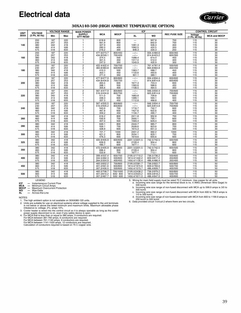
39
30XA140-500 (HIGH AMBIENT TEMPERATURE OPTION)
LEGEND
NOTES:1. The high ambient option is not available on 30XA080-120 units.2. Units are suitable for use on electrical systems where voltage supplied to the unit terminals
is not below or above the listed minimum and maximum limits. Maximum allowable phaseimbalance is: voltage, 2%; amps 10%.
3. Cooler heater is wired into the control circuit so it is always operable as long as the contolpower supply disconnect is on, even if any safety device is open.
4. For MCA that is less than or equal to 380 amps, 3 conductors are required.For MCA between 381-760 amps, 6 conductors are required.For MCA between 761-1140 amps, 9 conductors are required.For MCA between 1141-1520 amps, 12 conductors are required.Calculation of conductors required is based on 75 C copper wire.
5. Wiring for main field supply must be rated 75 C minimum. Use copper for all units.a. Incoming wire size range for the terminal block is no. 4 AWG (American Wire Gage) to
500 kcmil.b. Incoming wire size range of non-fused disconnect with MCA up to 599.9 amps is 3/0 to
500 kcmil.c. Incoming wire size range of non-fused disconnect with MCA from 600 to 799.9 amps is
1/0 to 500 kcmil.d. Incoming wire size range of non-fused disconnect with MCA from 800 to 1199.9 amps is
250 kcmil to 500 kcmil.6. Data provided circuit 1/circuit 2 where there are two circuits.
UNIT30XA
VOLTAGE(3 Ph, 60 Hz)
VOLTAGE RANGE MAIN POWERSUPPLY
QTY REQDMCA MOCP
ICFREC FUSE SIZE
CONTROL CIRCUIT
Min Max XL WD Voltage(1 Ph, 60 Hz) MCA and MOCP
140
200 187 220 1 618.8 800 — 957.8 700 115 30230 207 253 1 561.9 800 — 842.9 700 115 30380 342 418 1 327.9 450 1281.3 506.3 400 115 30460 414 506 1 282.0 400 1062.5 422.5 350 115 30575 518 633 1 216.2 300 846.3 334.3 250 115 30
160
200 187 220 2 477.9/273.7 800/450 —/— 934.4/484.6 600/350 115 30230 207 253 2 434.8/249.1 700/400 —/— 814.8/423.2 600/300 115 30380 342 418 1 374.5 500 1588.4 614.4 450 115 30460 414 506 1 321.5 450 1317.0 512.0 400 115 30575 518 633 1 247.0 350 1049.9 405.9 300 115 30
180
200 187 220 2 422.4/422.4 700/700 —/— 761.4/761.4 500/500 115 30230 207 253 2 383.8/383.8 600/600 —/— 664.8/664.8 450/450 115 30380 342 418 1 410.3 500 1363.7 588.7 450 115 30460 414 506 1 353.1 450 1133.6 493.6 400 115 30575 518 633 1 271.0 350 901.1 389.1 300 115 30
200
200 187 220 2 477.9/477.9 800/800 —/— 934.4/934.4 600/600 115 30230 207 253 2 434.8/434.8 700/700 —/— 814.8/814.8 600/600 115 30380 342 418 1 463.4 600 1677.3 703.3 600 115 30460 414 506 1 398.1 500 1393.6 588.6 450 115 30575 518 633 1 305.6 400 1108.5 464.5 350 115 30
220
200 187 220 2 567.4/477.9 800/800 —/— 946.3/934.4 700/600 115 30230 207 253 2 516.0/434.8 800/700 —/— 825.6/814.8 700/600 115 30380 342 418 1 511.0 700 1683.8 709.8 600 115 30460 414 506 1 439.3 600 1399.1 594.1 500 115 30575 518 633 1 337.3 450 1112.8 468.8 400 115 30
240
200 187 220 2 567.4/555.5 800/800 —/— 946.3/934.4 700/700 115 30230 207 253 2 516.0/505.2 800/800 —/— 825.6/814.8 700/600 115 30380 342 418 1 543.9 700 1716.7 742.7 600 115 30460 414 506 1 467.8 600 1427.6 622.6 600 115 30575 518 633 1 359.2 450 1134.7 490.7 400 115 30
260380 342 418 1 616.2 800 2411.8 952.8 700 115 30460 414 506 1 530.6 700 2000.1 795.1 600 115 30575 518 633 1 407.0 500 1593.4 629.4 500 115 30
280380 342 418 1 649.1 800 2444.7 985.7 800 115 30460 414 506 1 559.1 700 2028.6 823.6 700 115 30575 518 633 1 428.9 600 1615.3 651.3 500 115 30
300380 342 418 1 721.7 1000 2451.2 992.2 1000 115 30460 414 506 1 621.2 800 2034.1 829.1 700 115 30575 518 633 1 476.3 600 1619.6 655.6 600 115 30
325380 342 418 2 405.9/405.9 600/600 2201.5/2201.5 742.5/742.5 500/500 115 30460 414 506 1 639.9 800 2109.4 904.4 800 115 30575 518 633 1 490.7 600 1677.1 713.1 600 115 30
350380 342 418 2 472.0/405.9 800/600 2201.5/2201.5 742.5/742.5 600/500 115 30460 414 506 1 696.4 800 2109.4 904.4 800 115 30575 518 633 1 533.8 700 1677.1 713.1 600 115 30
400380 342 418 2 399.4/537.4 600/700 2195.0/1710.2 736.0/736.2 500/600 115 50460 414 506 2 344.5/462.3 500/600 1814.0/1422.2 609.0/617.2 450/600 115 50575 518 633 2 264.0/354.9 400/450 1450.4/1130.4 486.4/486.4 350/400 115 50
450380 342 418 2 465.5/652.2 700/800 2195.0/2381.7 736.0/922.7 600/800 115 50460 414 506 2 401.0/561.6 600/800 1814.0/1974.6 609.0/769.6 500/700 115 50575 518 633 2 307.2/430.5 500/600 1450.4/1573.7 486.4/609.7 400/500 115 50
500380 342 418 2 465.5/708.7 700/1000 2195.0/2438.2 736.0/979.2 600/800 115 50460 414 506 2 401.0/610.2 600/ 800 1814.0/2023.2 609.0/818.2 500/700 115 50575 518 633 2 307.2/467.7 500/ 600 1450.4/1611.0 486.4/647.0 400/600 115 50
ICF — Instantaneous Current FlowMCA — Minimum Circuit AmpsMOCP — Maximum Overcurrent ProtectionWD — Wye-DeltaXL — Across-the-Line
Electrical data

40
30XA080-500 (STANDARD CONDENSER FAN MOTORS)
LEGEND
NOTES:1. Units are suitable for use on electrical systems where voltage supplied to the unit terminals
is not below or above the listed minimum and maximum limits. Maximum allowable phaseimbalance is: voltage, 2%; amps 10%.
2. Cooler heater is wired into the control circuit so it is always operable as long as the contolpower supply disconnect is on, even if any safety device is open.
3. For MCA that is less than or equal to 380 amps, 3 conductors are required.For MCA between 381-760 amps, 6 conductors are required.For MCA between 761-1140 amps, 9 conductors are required.For MCA between 1141-1520 amps, 12 conductors are required.Calculation of conductors required is based on 75 C copper wire.
4. Wiring for main field supply must be rated 75 C minimum. Use copper for all units.a. Incoming wire size range for the terminal block is no. 4 AWG (American Wire Gage) to
500 kcmil.b. Incoming wire size range of non-fused disconnect with MCA up to 599.9 amps is 3/0 to
500 kcmil.c. Incoming wire size range of non-fused disconnect with MCA from 600 to 799.9 amps is
1/0 to 500 kcmil.d. Incoming wire size range of non-fused disconnect with MCA from 800 to 1199.9 amps is
250 kcmil to 500 kcmil.5. Data provided circuit 1/circuit 2 where there are two circuits.
UNIT30XA
VOLTAGE(3 Ph, 60 Hz)
VOLTAGE RANGE MAIN POWERSUPPLY
QTY REQDMCA MOCP
ICFREC FUSE
SIZE
CONTROL CIRCUIT
Min Max XL WD Voltage(1 Ph, 60 Hz)
MCA andMOCP
080
200 187 220 1 347.6 450 1257.6 521.6 400 115 30230 207 253 1 315.5 400 1100.2 460.2 350 115 30380 342 418 1 183.5 250 662.7 275.7 225 115 30460 414 506 1 157.7 200 550.1 230.1 175 115 30575 518 633 1 121.2 150 437.9 181.9 150 115 30
090
200 187 220 1 368.0 500 1274.0 538.0 450 115 30230 207 253 1 334.0 450 1115.1 475.1 400 115 30380 342 418 1 194.5 250 671.6 284.6 225 115 30460 414 506 1 167.0 225 557.6 237.6 200 115 30575 518 633 1 128.5 175 443.8 187.8 150 115 30
100
200 187 220 1 401.3 500 1564.8 644.8 450 115 30230 207 253 1 364.6 500 1368.7 568.7 400 115 30380 342 418 1 212.7 250 824.7 340.7 250 115 30460 414 506 1 182.3 250 684.4 284.4 200 115 30575 518 633 1 139.5 175 544.7 224.7 175 115 30
110
200 187 220 1 446.2 600 — 644.8 500 115 30230 207 253 1 405.7 500 — 568.7 450 115 30380 342 418 1 236.4 300 824.7 340.7 300 115 30460 414 506 1 202.4 250 684.4 284.4 225 115 30575 518 633 1 155.5 200 544.7 224.7 175 115 30
120
200 187 220 1 482.2 600 — 680.8 600 115 30230 207 253 1 438.6 600 — 601.6 500 115 30380 342 418 1 255.3 350 843.6 359.6 300 115 30460 414 506 1 218.4 300 700.4 300.4 250 115 30575 518 633 1 168.4 225 557.5 237.5 200 115 30
140
200 187 220 1 588.5 800 — 911.1 700 115 30230 207 253 1 534.7 800 — 800.7 700 115 30380 342 418 1 311.2 450 1255.9 480.9 350 115 30460 414 506 1 267.3 400 1040.4 400.4 350 115 30575 518 633 1 205.0 300 829.5 317.5 250 115 30
160
200 187 220 2 465.6/264.9 800/450 —/— 902.8/463.5 600/350 115 30230 207 253 2 423.5/241.0 700/400 —/— 786.0/404.0 600/300 115 30380 342 418 1 361.1 500 1564.9 590.9 450 115 30460 414 506 1 309.7 450 1296.4 491.4 350 115 30575 518 633 1 238.1 350 1034.3 390.3 300 115 30
180
200 187 220 2 407.2/407.2 700/700 —/— 729.8/729.8 500/500 115 30230 207 253 2 370.0/370.0 600/600 —/— 636.0/636.0 450/450 115 30380 342 418 1 391.5 500 1336.2 561.2 450 115 30460 414 506 1 336.6 450 1109.6 469.6 400 115 30575 518 633 1 258.3 350 882.8 370.8 300 115 30
200
200 187 220 2 465.6/465.6 800/800 —/— 902.8/902.8 600/600 115 30230 207 253 2 423.5/423.5 700/700 —/— 786.0/786.0 600/600 115 30380 342 418 1 447.2 600 1651.0 677.0 500 115 30460 414 506 1 383.9 500 1370.6 565.6 450 115 30575 518 633 1 294.8 400 1091.0 447.0 350 115 30
220
200 187 220 2 554.7/548.0 800/800 —/— 909.4/902.8 700/600 115 30230 207 253 2 504.2/423.5 800/700 —/— 792.0/786.0 600/600 115 30380 342 418 1 494.5 700 1654.6 680.6 600 115 30460 414 506 1 424.7 600 1373.6 568.6 500 115 30575 518 633 1 326.3 450 1093.4 449.4 400 115 30
240
200 187 220 2 554.7/548.0 800/800 —/— 909.4/902.8 700/700 115 30230 207 253 2 504.2/498.2 800/800 —/— 792.0/786.0 600/600 115 30380 342 418 1 529.5 700 1689.5 715.5 600 115 30460 414 506 1 455.0 600 1403.9 598.9 600 115 30575 518 633 1 349.6 450 1116.7 472.7 400 115 30
260380 342 418 1 600.2 800 2376.9 917.9 700 115 30460 414 506 1 516.5 700 1969.6 764.6 600 115 30575 518 633 1 396.4 500 1570.2 606.2 450 115 30
280380 342 418 1 638.2 800 2414.9 955.9 800 115 30460 414 506 1 549.8 800 2002.9 797.9 700 115 30575 518 633 1 422.0 600 1595.9 631.9 500 115 30
300380 342 418 1 710.3 1000 2415.4 956.4 800 115 30460 414 506 1 610.9 800 2002.9 797.9 700 115 30575 518 633 1 468.7 600 1595.9 631.9 600 115 30
325380 342 418 2 426.0/426.0 700/700 2202.7/2202.7 743.7/743.7 500/500 115 30460 414 506 1 624.3 800 2077.5 872.5 700 115 30575 518 633 1 479.1 600 1652.9 688.9 600 115 30
350380 342 418 2 497.6/426.0 800/700 2202.7/2202.7 743.7/743.7 600/500 115 30460 414 506 1 685.5 800 2077.5 872.5 800 115 30575 518 633 1 525.7 700 1652.9 688.9 600 115 30
400380 342 418 2 419.4/561.9 700/700 2196.1/1722.0 737.1/748.0 500/700 115 50460 414 506 2 340.9/452.0 500/600 1794.0/1400.9 589.0/595.9 450/500 115 50575 518 633 2 261.4/347.2 450/450 1435.2/1114.3 471.2/470.3 350/400 115 50
450380 342 418 2 490.9/685.4 800/1000 2196.1/2390.5 737.1/931.5 600/500 115 50460 414 506 2 402.0/553.6 700/ 800 1794.0/1945.6 589.0/740.6 500/700 115 50575 518 633 2 308.0/424.4 500/ 600 1435.2/1551.6 471.2/587.6 400/500 115 50
500380 342 418 2 490.9/745.1 800/1000 2196.1/2450.2 737.1/991.2 600/1000 115 50460 414 506 2 402.0/604.9 700/ 800 1794.0/1996.9 589.0/791.9 500/ 700 115 50575 518 633 2 308.0/463.9 500/ 600 1435.2/1591.1 471.2/627.1 400/ 600 115 50
ICF — Instantaneous Current FlowMCA — Minimum Circuit AmpsMOCP — Maximum Overcurrent ProtectionWD — Wye-DeltaXL — Across-the-Line
Electrical data (cont)

41
MicroprocessorThe ComfortLink™ microprocessor controls overall unitoperation and controls a number of processes simulta-neously. These processes include internal timers, readinginputs, analog to digital conversions, fan control, displaycontrol, diagnostic control, output relay control, demandlimit, capacity control, head pressure control, and tempera-ture reset. Some processes are updated almost continuously,others every 2 to 3 seconds, and some every 30 seconds.The microprocessor routine is started by switching theEmergency ON-OFF switch to ON position. Pump controlof external pumps (where configured) will energize thecooler pump to the internal (or CCN) time schedule (or inputoccupied signal from external system).
When the unit receives a call for cooling (based on adeviation from chilled water set point), the unit stages up incapacity to maintain the cooler fluid set point. The firstcompressor starts 1 to 3 minutes after the call for cooling.The ComfortLink microprocessor controls the capacity ofthe chiller by varying the number of compressors on andeach loading capacity to satisfy actual dynamic load condi-tions. The control maintains leaving-fluid temperature setpoint shown on the Navigator™ device through intelligentpositioning of the slide valve and compressor cycling.Accuracy depends on loop volume, loop flow rate, load,and outdoor-air temperature. No adjustment for coolingrange or cooler flow rate is required, because the controlautomatically compensates for cooling range by measuringboth return-fluid temperature and leaving-fluid tempera-ture. This is referred to as leaving-fluid temperature controlwith return-fluid temperature compensation.
The basic logic for determining when to add or removecapacity is a time band integration of deviation from setpoint plus rate of change of leaving-fluid temperature.When leaving-fluid temperature is close to the set pointand slowly moving closer, logic prevents additional capac-ity. If leaving-fluid temperature is less than 34 F (1.1 C) forwater, or 6° F (3.3° C) below the brine freeze set point forbrine units, the unit is shut off until the water temperaturefor brine reaches 34 F (1.1 C) or to 6° F (3.3° C) above theset point for brine to protect against freezing.
If pulldown control has been selected (adjustable setting),no additional capacity is added as long as the differencebetween leaving-fluid temperature and the set point isgreater than 4° F (2.2° C) and rate of change in leaving-water temperature is greater than the adjustable setting. Ifit has been less than 90 seconds since the last capacitychange, compressors will continue to run unless a safetydevice trips. This prevents rapid cycling and also helpsreturn oil during short operating periods.
Control sequenceOff cycle — If ambient temperature is below 36 F (2.2 C),cooler heaters are also energized.Start-up — After control circuit switches on, the prestartprocess takes place, then microprocessor checks itself,starts pump (if configured) and waits for temperature tostabilize. The controlled pulldown feature limits compres-sor loading on start-up to reduce demand on start-up andunnecessary compressor usage.
Capacity control — On the first call for cooling, themicroprocessor starts initial compressor and fan stage onlead circuit.
As additional cooling is required, the capacity of thecompressor is increased by changing the position of theslide valve. As the load increases above the compressor’scapacity, another compressor is started and both stagedtogether.
The speed at which capacity is added or reduced is con-trolled by temperature deviation from set point and rate oftemperature change of chilled fluid.
The Main Base Board (MBB) responds to the supplychilled water temperature to cycle the compressors tomatch cooling load requirements.
The Minimum Load control valve is energized by theMBB. The valve allows hot gas to pass directly into thecooler circuit on the initial step of unloading, permittingthe unit to operate at lower loads with less compressorcycling.
SensorsThermistors are used to control temperature-sensing inputsto the microprocessor. No additional thermistor sensors arerequired for optional leaving chilled water temperature,return water, or outdoor air reset.The following sensors can be used on 30XA units:• Cooler leaving chilled fluid temperature (T1)• Cooler entering fluid (return) temperature (T2)• Outside-air temperature (T9)• Space Temperature (T10)
Two refrigerant pressure transducers are used in eachcircuit for sensing suction and discharge pressure. Themicroprocessor uses these inputs to control capacity andfan cycling.• Saturated condensing temperature• Cooler saturation temperature• Oil• Economizer
Additional informationDetailed information on controls and operation is availablein the Controls, Start-Up, Operation, Service, and Trouble-shooting guide included with each unit. Packaged ServiceTraining programs are also available. Contact a localCarrier representative for more information.Dynamic ComfortLink controls keep the chiller online during periods of extreme operating conditions. If theentering fluid temperature is 95 F (35 C) and the saturatedsuction temperature is 50 F (10 C) or higher the maximumoperating pressure (MOP) feature limits the suction to keepthe chiller online. The control automatically starts thechiller in the unloaded state to eliminate the potential ofcompressor overload due to high head pressure or low suc-tion pressure. The controller will equalize run time on eachcircuit through the lead/lag feature. If a circuit becomesdisabled, the control will automatically set the active circuitto lead, keeping the chiller online at a reduced capacity.
Controls

42
Standard ComfortLink™ controls with Navigator™display — A portable hand-held display for convenientaccess to unit status, operation, configuration and trouble-shooting diagnostics capability is standard on 30XA units.The four-line, 20-character LCD display provides clearlanguage information in English, French, Spanish, orPortuguese. The weatherproof enclosure and industrialgrade extension cord enable the Navigator display to beideally suited for outdoor applications. Magnets located onthe back of the module allow attachment to any sheetmetal component for hands-free operation.Low-temperature override — This feature preventsLCWT (leaving chilled water temperature) from overshoot-ing the set point and possibly causing a nuisance trip-outby the freeze protection.High-temperature override — This feature allows thechiller to add capacity quickly during rapid load variations.Temperature reset The Energy Management Module is required for 4 to20 mA reset of LCWT in constant fluid systems. Reset byreturn fluid, outdoor-air temperature, or space temperaturedoes not require this option. Reset reduces compressorpower usage at part load when design LCWT is not neces-sary. Humidity control should be considered since highercoil temperatures resulting from reset will reduce latentheat capacity. Three reset options are offered, based onthe following: Return-Fluid Temperature increases LCWT set point asreturn (or entering) fluid temperature decreases (indicatingload decrease). Option may be used in any applicationwhere return fluid provides accurate load indication. A limi-tation of return fluid reset is that LCWT may only be resetto value of design return fluid temperature.Outdoor-Air Temperature increases the LCWT as outdoorambient temperature decreases (indicating load decrease).This reset should be applied only where outdoor ambienttemperature is an accurate indication of load.Space Temperature increases the LCWT as space temper-ature decreases (indicating load decrease). This resetshould be applied only where space temperature is anaccurate indication of load. An accessory space tempera-ture thermistor is required.
For details on applying a reset option, refer to theControls, Start-Up, Operation, Service and Troubleshoot-ing literature shipped with the unit. Obtain ordering partnumbers for reset option from the Packaged ChillerBuilder program or contact a local Carrier representative.Abnormal conditions — All control safeties in the chilleroperate through compressor protection board or controlrelay and microprocessor.
Loss of feedback signal to the MBB will cause the com-pressor(s) to shut down. For other safeties, microprocessormakes appropriate decision to shut down a compressordue to a safety trip or bad sensor reading and displaysappropriate failure code on the display. Chiller holds insafety mode until reset; it then reverts to normal controlwhen unit is reset.Low-pressure safety — Safety cuts out if system pres-sure drops below minimum.
High-pressure cutout — Switch shuts down compres-sors if compressor discharge pressure increases to305 psig (2102.7 kPa).Compressor anti-cycling — This feature limits com-pressor cycling.Loss of flow protection — Proof of flow switches arestandard and installed on all 30XA chillers.Sensor failures — Failures are detected by themicroprocessor.Accessory controls — Demand can be limited by con-trolling the chiller capacity through the demand limitcontrol (the Energy Management Module is required forthis function). This FIOP/accessory interfaces with themicroprocessor to control the unit so that the chiller’s kWdemand does not exceed its setting. It is activated from anexternal switch or a 4 to 20 mA signal.
The standard ComfortLink control is programmed toaccept various accessory temperature reset options (basedon outdoor-air temperature [standard], return-fluid temper-ature [standard], or space temperature [which requiresaccessory thermistor]), that resets the LCWT. An accessorythermistor (T10) is required if space temperature reset isselected. The Energy Management Module (EMM) is onlyrequired for temperature reset that is initiated by a 4 to20 mA signal.Demand limit — If the demand limit is applied, it limitsthe total power draw of unit to a selected point by control-ling the number of operational compressors during periodsof peak electrical demand.
The Energy Management Module is required for either2-step or 4 to 20 mA demand limit.Electronic expansion valve (EXV) — The EXV con-trols refrigerant flow to the cooler for different operatingconditions by varying an orifice size to increase or decreasethe flow area through the valve based on microprocessorinput. The orifice is positioned by a stepper motor throughapproximately 3,600 discrete steps and is monitored everythree seconds.Diagnostics — The microprocessor may be put througha service test (see Controls, Start-Up, Operation, Service,and Troubleshooting literature). Service test confirmsmicroprocessor is functional, informs observer through dis-play the condition of each sensor and switch in chiller, andallows observer to check for proper operation of fans andcompressors.Default settings — To facilitate quick start-ups, 30XAchillers with ComfortLink controls are pre-configured witha default setting that assumes stand-alone operation sup-plying 44 F (6.6 C) chilled water.
Configuration settings will be based on any optionsor accessories included with the unit at the time ofmanufacturing.
Date and time are set to U.S.A. Eastern Time zone andwill need reconfiguring based on location and local timezone. If operation based on occupancy scheduling isdesired, schedule must be set during installation.
Controls (cont)

43
Ice duty — ComfortLink™ controls have the capability ofreduced leaving fluid temperature operation for thermalstorage, or ice duty. The optional Energy Managementdisplay includes input contacts for the “ice done” signalgenerated by the thermal storage control system. The iceduty feature may be configured to start on an externalinput command or by the ComfortLink standard internalscheduling function. The ice duty function requires brinemodification for leaving fluid temperatures below 40 F(4.4 C). Ice duty may be used in combination with anyother standard features offered by the Energy ManagementModule and ComfortLink controls.
The production of ice, which is stored for peak coolingdemands, can significantly decrease energy costs. The unitproduces ice (normally at night) by supplying ice storagetanks with low temperature cooling fluid. The chiller takesadvantage of reduced ambient conditions at night for ice-making mode, so the capacity suffers a lower penalty forthe low leaving fluid temperatures.
At peak cooling demands, the chiller and the stored icemay share the cooling load to reduce operating costs. Thethermal storage system may potentially reduce the size ofthe chiller plant required to meet demand loads.

44
Controls and power wiring schematic,sizes 080-500
MA
IN P
OW
ER
EN
TR
AN
CE
CIR
CU
IT 2
400-
500
ALL
VO
LTA
GE
S
MA
IN P
OW
ER
EN
TR
AN
CE
CIR
CU
IT 1
140-
500
ALL
VO
LTA
GE
S
PE
B 1
PE
B 2
TY
PIC
AL
CO
NT
RO
L B
OX
LO
CA
TIO
NS
AN
D M
AIN
PO
WE
R E
NT
RY
FE
B
080-
120
MA
IN P
OW
ER
E
NT
RY
ALL
VO
LTA
GE
S
FIE
LDS
CO
NT
RO
LW
IRIN
G E
NT
RY
FIE
LD C
ON
TR
OL
WIR
ING
EN
TR
Y
080-
120
MA
IN P
OW
ER
DIS
PLA
Y L
OC
AT
ION
(140
- 500
UN
I TS
DIS
PLA
Y L
OC
AT
ION
IS
IN C
LOS
E P
RO
XIM
ITY
TO
TH
E
PO
WE
R B
OX
.)
NO
TE
S:
1.Fa
ctor
yw
iring
isin
acco
rdan
cew
ithU
L19
95st
anda
rds.
Fie
ldm
odifi
catio
nsor
addi
tions
mus
tbe
inco
mpl
ianc
ew
ithal
lapp
licab
leco
des.
2.W
iring
for
mai
nfie
ldsu
pply
mus
tbe
rate
d75
Cm
inim
um.U
seco
pper
for
allu
nits
.In
com
ing
wire
size
rang
efo
run
its08
0-12
0,al
lvol
tage
sis
4-50
0kc
mil.
Inco
min
gw
iresi
zera
nge
for
units
140-
240,
200/
230
vis
1/0-
500
kcm
il.In
com
ing
wire
size
rang
efo
run
its14
0-24
0,38
0,46
0,57
5v
is4-
500
kcm
il.In
com
ing
wire
size
rang
efo
run
its26
0-50
0,38
0,46
0,57
5v
is1/
0-50
0kc
mil.
3.Te
rmin
als
9an
d10
ofT
B5
are
for
field
exte
rnal
conn
ectio
nsfo
rre
mot
eon
-off.
The
cont
acts
mus
tbe
rate
dfo
rdr
yci
rcui
tapp
licat
ion
capa
ble
ofha
ndlin
ga
24va
clo
adup
to50
mA
.4.
Term
inal
s1
and
2of
TB
5ar
efo
rex
tern
alco
nnec
tions
ofch
illed
wat
erpu
mp
inte
rlock
.The
cont
acts
mus
tbe
rate
dfo
rdr
yci
rcui
tapp
licat
ion
capa
ble
ofha
ndlin
ga
24va
clo
adup
to50
mA
.5.
Term
inal
s11
and
13of
TB
5ar
efo
rco
ntro
lof
chill
edw
ater
pum
p1
(PM
P1)
star
ter.
Term
inal
s13
and
15of
TB
5ar
efo
rco
ntro
lof
chill
edw
ater
pum
p2
(PM
P2)
star
ter.
The
max
imum
load
allo
wed
for
the
chill
edw
ater
pum
pre
lay
is5
vase
aled
,10
vain
rush
at24
v.F
ield
pow
ersu
pply
isno
tre
quire
d.6.
For
cont
rolo
fch
illed
wat
erpu
mps
,a
set
ofno
rmal
lyop
enco
ntac
tsra
ted
for
dry
circ
uita
pplic
atio
nm
ust
besu
pplie
dfr
omfie
ld-s
uppl
ied
pum
pst
arte
rre
lay.
Con
nect
cont
acts
tovi
olet
and
pink
wire
sin
harn
ess
from
mai
nba
sebo
ard
chan
nel
18.
Wire
sin
harn
ess
are
mar
ked
PM
P1-
13an
dP
MP
1-14
.7.
Term
inal
s12
and
13of
TB
5ar
efo
ran
alar
mre
lay.
The
max
imum
load
allo
wed
for
the
alar
mre
lay
is10
vase
aled
,25
vain
rush
at24
v.F
ield
pow
ersu
pply
isno
treq
uire
d.8.
Mak
eap
prop
riate
conn
ectio
nsto
TB
6as
show
nfo
ren
ergy
man
agem
ent
boar
dop
tions
.T
heco
n-ta
cts
for
occu
panc
yov
errid
e,de
man
dlim
itan
dic
edo
neop
tions
mus
tbe
rate
dfo
rdr
yci
rcui
tap
plic
atio
nca
pabl
eof
hand
ling
a24
vac
load
upto
50m
A.
LEG
EN
D
A—
Ala
rmE
MM
—E
nerg
yM
anag
emen
tF
EB
—Fa
nE
lect
rical
Box
MLV
—M
inim
umLo
adV
alve
NE
C—
Nat
iona
lEle
ctric
Cod
eP
EB
—P
ower
Ele
ctric
alB
oxP
MP
—C
hille
dW
ater
Pum
pP
MP
I—
Chi
lled
Wat
erP
ump
Inte
rlock
TB
—Te
rmin
alB
lock
Fie
ldP
ower
Wiri
ngF
ield
Con
trol
Wiri
ngFa
ctor
yIn
stal
led
Wiri
ng

45
Chiller location and clearancesDo not locate near sound sensitive areas without properacoustic consideration. For applications requiring mount-ing a chiller on a building rooftop, consideration should begiven to using rubber-in-shear or spring isolators to mini-mize structure-borne transmission. Unit must be level wheninstalled to ensure proper oil return to the compressors.Clearances must be provided around chillers for airflow,service and local code requirements. See dimensionaldrawings for specific unit clearance requirements. Ensureadequate clearance between adjacent chillers is main-tained. A minimum of 10 ft is recommended. Chiller fandischarge must be at least as high as adjacent solid walls.Installation in pits is not recommended.
StrainersA strainer with a minimum screen size of 20 mesh must beinstalled in the entering cooler fluid line, no more than10 ft ahead of the cooler.
Oversizing chillersOversizing chillers by more than 15% at design conditionsmust be avoided as the system operating efficiency isadversely affected (resulting in greater or excessive electri-cal demand). When future expansion of equipment isanticipated, install a single chiller to meet present loadrequirements and add a second chiller to meet the addi-tional load demand. It is also recommended that 2 smallerchillers be installed where operation at minimum load iscritical. The operation of a smaller chiller loaded to agreater percentage over minimum is preferred to operatinga single chiller at or near its minimum recommended value.Minimum Load Control should not be used as a means toallow oversizing chillers. Minimum Load Control should begiven consideration where substantial operating time isanticipated below the minimum unloading step.
Cooler water temperature1. Maximum leaving chilled water temperature (LCWT)
for the unit is 60 F (15.5 C). Unit can start andpull down with up to 95 F (35 C) entering-watertemperature. It is recommended that entering-watertemperature not exceed 70 F (21.1).
2. Minimum LCWT for a standard unit is 40 F (4.4 C).For leaving-water temperatures between 15 and39.9 F (–9.4 to 43 C) an inhibited antifreeze solutionis required. Application of chiller to 15 F (–9.4 C) ispossible by ordering the factory-installed mediumtemperature brine option.
NOTE: Water flowing through cooler should not exceed100 F.
Cooler flow/rangeRatings and performance data in this publication are for acooling temperature rise of 10° F (5.5° C). The 30XA chill-ers may be operated at a different temperature rise, provid-ing flow limits are not exceeded and corrections to systemguidelines are made. For minimum and maximum coolerflow rates, see the Minimum and Maximum Cooler FlowRates table. A high flow rate is generally limited by themaximum pressure drop that can be tolerated by the unit.The 30XA chillers are designed for a full load temperaturerise of 5° to 20° F (2.8° to 11.1° C). Use the Packaged
Chiller Program to obtain the rating if a temperature riseother than 10° F (5.5° C) is used.Minimum cooler flow (maximum cooler tempera-ture rise) — The minimum cooler flow for standard unitsis shown in the Minimum and Maximum Cooler FlowRates table. When system design conditions require alower flow (or higher rise) than the minimum allowablecooler flow, follow the recommendations below.a. Multiple smaller chillers may be applied in series, each
providing a portion of the design temperature rise.b. Cooler fluid may be recirculated to raise the flow rate to
the chiller. However, the mixed temperature enteringcooler must be maintained a minimum of at least 5 F(2.8 C) above the LCWT.
NOTE: Recirculation flow is shown below.
Maximum cooler flow — The maximum cooler flow(approximately 5° F rise) results in a practical maximumpressure drop through cooler.
Return fluid may bypass the cooler to keep the pressuredrop through the cooler within acceptable limits. This per-mits a higher delta T with lower fluid flow through coolerand mixing after the cooler.NOTE: Bypass flow is shown below.
Variable cooler flow ratesVariable rates may be applied to a standard chiller. The unitwill, however, attempt to maintain a constant leavingchilled water temperature. In such cases minimum flowmust be in excess of minimum flow given in the Minimumand Maximum Cooler Fluid Flow Rates table, and mini-mum water volume must be in excess of 3 gallons per ton(3.2 l/kw). Flow rate must change in steps of less than10% per minute. Apply 6 gal. or more per ton (6.5 l/kw)water loop volume minimum if flow rate changes morerapidly.
Application data
RECIRCULATION FLOW
BYPASS FLOW

46
Water loop volumeThe volume in circulation must equal or exceed 3 gal. pernominal ton (6.5 l/kW) of cooling for temperature stabilityand accuracy in normal air conditioning applications. Inprocess cooling applications, or for operation at ambienttemperature below 32 F (0° C) with low loading condi-tions, there should be from 6 to 10 gal. per ton (6.5 to10.8 l/kW). To achieve this volume, it is often necessary toinstall a tank in the loop.
Tank should be baffled to ensure there is no stratificationand that water (or brine) entering tank is adequately mixedwith liquid in the tank.
Cooler fouling factorThe fouling factor used to calculate tabulated ratings is0.001 ft2 ⋅ hr ⋅ °F/Btu (.000018 m2 ⋅ °C/W). As foulingfactor is increased, unit capacity decreases and compressorpower increases. Corrections to published ratings can beapproximated by using the following multipliers:
FOULING FACTORS
Cooler freeze protectionFreeze protection for the cooler is standard on all 30XAair-cooled chillers. All units are equipped with cooler heat-ers. Units are protected from freezing down to 0° F (–18 C)through the cooler heaters and control algorithms. If a unitcontrols the chilled water pump/valves, allowing for flowthrough the cooler, the unit is protected from freezingdown to –20 F (–29 C). Since power is sometimes lost forextended periods during winter storms, freeze protectionprovided by heater tapes will be effective only if a back-uppower supply can be assured for the unit’s control circuit,heater and cooler pump. If not protected with an anti-freeze solution, draining the cooler and outdoor piping isrecommended if the system will not be used during freezingweather conditions.
Two conditions that must be considered when determin-ing antifreeze concentration are both leaving water setpoint and ambient freeze conditions. Both of these param-eters can help determine the recommended concentrationlevel. Higher concentration must be used to adequatelyprotect the machine.NOTE: Use only antifreeze solutions approved for heat ex-changer duty.
For applications in which the leaving water temperatureset point is less than 40 F (4.4 C), a suitable inhibited anti-freeze solution must be used. The solution concentrationmust be sufficient to protect the chilled water loop to afreeze protection (first crystals) concentration of at least15° F (8.3° C) below the leaving water temperature setpoint.
If the chiller refrigerant or fluid lines are in an area whereambient conditions fall below 34º F (1.1º C), it is requiredthat an antifreeze solution be added to protect the unit andfluid piping to a temperature of 15º F (8.3° C) below thelowest anticipated ambient temperature.
Select concentration based on either burst or freeze pro-tection as dictated by the application. If the chiller does notoperate during the winter, nor is a start-up expected, aburst protection concentration is recommended. This con-centration may not be high enough to pump the fluidthrough the unit. Burst protection is typically a lower con-centration that will provide better performance from themachine. If the chiller does operate during winter, a freezeprotection concentration is recommended. This concentra-tion will be high enough to keep the fluid in a conditionthat it can be pumped at low ambient conditions.
Consult glycol fluid manufacturers for burst protectionrecommendations and fluid specifications.
High ambient temperature operationHigh outdoor ambient chiller start-up and operation is pos-sible for standard 30XA chillers at ambient temperaturesup to 125 F (52 C) at nominal voltage.
Low ambient temperature operationUnits will start and operate down to 32 F (0° C) asstandard. Operation to –20 F (–29 C) requires optionallow ambient head pressure control as well as wind baffles(field fabricated and installed to all units for operationbelow 32 F [0° C]) if wind velocity is anticipated to begreater than 5 mph (8 kp/h). Inhibited propylene glycol orother suitable corrosion-resistant anti-freeze solution mustbe field supplied and installed in all units for unit operationbelow 34 F (1.1 C). Solution must be added to fluid loop toprotect loop down to 15° F (8.3° C) below minimum oper-ating ambient temperature. Concentration should be basedon expected minimum temperature and either “Burst” or“Freeze” protection levels. At least 6 gal per ton (6.5 l/kw)of water volume is the recommended minimum for a mod-erate system load.
FOULING FACTOR(English)
(ft2 ⋅ hr ⋅ F/Btu)
FOULING FACTOR(SI)
(m2 ⋅ °C/W)
CAPACITYMULTIPLIER
COMPRESSORPOWER
MULTIPLIER.00025 .000044 0.991 0.995.00050 .000088 0.977 0.987.00075 .000132 0.955 0.979.00175 .000308 0.910 0.952
IMPORTANT: Glycol anti-freeze solutions are highlyrecommended since heater tapes provide no protectionin the event of a power failure.
Application data (cont)
BAD
BAD
GOOD
GOOD
TANK INSTALLATION

47
MINIMUM AND MAXIMUM COOLER FLOW RATES*
*Maximum ambient temperature and percent of unit capacity will vary based on unitload and return water temperature. All models are qualified for use at 125 F (46 C).Some models may require the high ambient fan option. Contact a local Carrier repre-sentative to obtain performance data using the Carrier electronic catalog.
†For applications requiring cooler leaving water temperature operation at less than40 F (4.4 C), the units require the use of antifreeze and application may require oneof the special order brine option. Contact a local Carrier representative for moreinformation.
**For applications requiring cooler entering water temperature operation at less than45 F (7.2 C), contact a local Carrier representative for unit selection using the Carrierelectronic catalog.
NOTES:1. The 30XA units will start with loop temperatures up to 95 F (35 C).2. Nominal flow rates required at ARI conditions 44 F (7 C) leaving fluid temperature,
54 F (12 C) entering water temperature, 95 F (35 C) ambient. Fouling factor0.00010 ft2-hr-F/Btu (0.000018 m2-K/kW).
3. To obtain proper temperature control, cooler loop fluid volume must be at least 3 gal/ton (3.23 L/kW) of chiller nominal capacity for air conditioning and at least 6 gal/ton(6.5 L/kW) for process applications or systems that must operate in low ambient tem-peratures (below 32 F [0° C]).
4. Where winds of 5 mph (2.2 m/s) or greater are anticipated at outdoor ambient tem-peratures below 32 F (0° C), wind baffles are required.
5. Requires optional or accessory low ambient kit for operation below 32 F (0° C).
ITEM MINIMUM MAXIMUM NOMINALCooler Leaving Water Temperature† 40 F (4.4 C) 60 F (15 C) —Cooler Entering Water Temperature** 45 F (7.2 C) 70 F (21.1 C) —
30XAUNIT SIZE Cooler Number of
PassesMinimum Flow Rate Maximum Flow Rate Nominal Flow Rate
(gpm) (L/s) (gpm) (L/s) (gpm) (L/s)
080Standard 2 95 6.0 379 23.9
180.4 11.4Plus one pass 3 43 2.7 192 12.1Minus one pass 1 196 12.4 782 49.3
090Standard 2 101 6.4 403 25.4
201.9 12.7Plus one pass 3 43 2.7 200 12.6Minus one pass 1 229 14.4 917 57.9
100Standard 2 101 6.4 403 25.4
225.5 14.2Plus one pass 3 43 2.7 200 12.6Minus one pass 1 229 14.4 917 57.9
110Standard 2 125 7.9 501 31.6
244.9 15.5Plus one pass 3 61 3.8 244 15.4Minus one pass 1 254 16.0 1014 64.0
120Standard 2 125 7.9 501 31.6
264.8 16.7Plus one pass 3 73 4.6 293 18.5Minus one pass 1 281 17.7 1124 70.9
140Standard 2 134 8.5 538 33.9
317.8 20.1Plus one pass 3 73 4.6 293 18.5Minus one pass 1 324 20.4 1296 81.8
160Standard 2 165 10.4 660 41.6
365.1 23.0Plus one pass 3 98 6.2 391 24.7Minus one pass 1 354 22.3 1418 89.5
180Standard 2 202 12.7 807 50.9
409.6 25.8Plus one pass 3 73 4.6 391 24.7Minus one pass 1 416 26.2 1662 104.9
200Standard 2 223 14.1 892 56.3
463.9 29.3Plus one pass 3 98 6.2 391 24.7Minus one pass 1 458 28.9 1833 115.6
220Standard 2 235 14.8 941 59.4
505.9 31.9Plus one pass 3 122 7.7 489 30.9Minus one pass 1 501 31.6 2004 126.4
240Standard 2 266 16.8 1063 67.1
545.8 34.4Plus one pass 3 147 9.3 587 37.0Minus one pass 1 538 33.9 2151 135.7
260Standard 2 257 16.2 1027 64.8
600.3 37.9Plus one pass 3 141 8.9 562 35.5Minus one pass 1 584 36.8 2334 147.3
280Standard 2 293 18.5 1173 74.0
642.2 40.5Plus one pass 3 141 8.9 562 35.5Minus one pass 1 620 39.1 2481 156.5
300Standard 2 327 20.6 1308 82.5
687.5 43.4Plus one pass 3 174 11.0 697 44.0Minus one pass 1 687 43.3 2750 173.5
325Standard 2 361 22.8 1442 91.0
733.4 46.3Plus one pass 3 211 13.3 843 53.2Minus one pass 1 724 45.7 2897 182.8
350Standard 2 379 23.9 1516 95.6
775.4 48.9Plus one pass 3 244 15.4 978 61.7Minus one pass 1 767 48.4 3068 193.6
400Standard 1 501 31.6 2004 126.4
917.6 57.9Plus one pass — — — — —Minus one pass — — — — —
450Standard 1 501 2004
1019.3 64.3Plus one pass — — — — —Minus one pass — — — — —
500Standard 1 501 2004
1092.8 68.9Plus one pass — — — — —Minus one pass — — — — —

48
Altitude correction factorsCorrection factors must be applied to standard ratingsat altitudes above 2000 ft (609.6 m) using the followingmultipliers:
ALTITUDE CORRECTION FACTORS
Condenser airflow — Airflow restrictions on units withstandard fans will affect the unit capacity, condenser headpressure, and compressor power input. Correction factorsto be applied for external static restrictions up to 0.2 in. wg(50 Pa) are as follows:
Multiple chillersWhere multiple chillers are required, or where standbycapability is desired, chillers may be installed in parallel.Units may be of the same size or different sizes. However,cooler flow rates must be balanced according to the recom-mendations for each chiller to ensure proper flow.
Unit software is capable of controlling two units as a sin-gle plant. Refer to the Controls, Start-Up, Operation, Ser-vice, and Troubleshooting guide for further details.
Dual chiller controlThe ComfortLink™ controller allows 2 chillers (piped inparallel or series) to operate as a single chilled water plantwith standard control functions coordinated through themaster chiller controller. This standard ComfortLink fea-ture requires a communication link between the 2 chillers.There are several advantages to this type of control:• Redundancy (multiple circuits)• Better low load control (lower tonnage capability)• Lower rigging lift weights (2 machines rather than
1 large machine)• Chiller Lead-Lag Operation (evens the wear between
the two machines)Parallel dual chiller operation — Parallel Chiller Oper-ation is the recommended option for Dual Chiller Control.In this case, each chiller must control its own dedicatedpump or isolation valve. Balancing valves are recom-mended to ensure proper flow in each chiller. Two field-supplied and installed dual chiller leaving water tempera-ture sensors are required, one for each module, for thisfunction to operate properly.
Consider adding additional isolation valves to isolateeach chiller to allow for service on a machine, and stillallow for partial capacity from the other chiller.Series dual chiller operation — Series Chiller Opera-tion is an alternate control method supported by theComfortLink control system. Certain applications might
require that the two chillers be connected in series. Fornominal 10 F (5.6 C) cooler ranges, use the Minus 1 PassCooler arrangement to reduce the fluid-side pressure drop.Use the standard cooler pass arrangement for low flow,high cooler temperature rise applications. Two field-supplied and installed dual chiller leaving water tempera-ture sensors are required, one for each module, for thisfunction to operate properly.
Consider adding additional piping and isolation valves toisolate each chiller to allow for service on a machine, andstill allow for partial capacity from the other chiller.
Condenser coil protection (Enviro-Shield™)Refer to the Environmental Corrosion Protection whitepaper for more information.Pre-coated aluminum-fin coils have a durable epoxy-phenolic coating applied to the fin prior to the fin stampingprocess to provide protection in mildly corrosive coastalenvironments. Pre-coated coils have an inert barrierbetween the aluminum fin and copper tube. This barrierelectrically disconnects the dissimilar metals to minimizethe potential for galvanic corrosion. This economicaloption provides substantial corrosion protection beyondthe standard uncoated coil construction.Copper-fin coils provide increased corrosion resistancein moderate coastal environments where industrial air pol-lution is not present. All copper coils eliminate bimetallicconstruction to eliminate the potential for galvanic corro-sion. Application in industrial environments is not recom-mended due to potential attack from sulfur, sulfur oxide,nitrogen oxides, carbon and several other industrial air-borne contaminants. In moderate seacoast environments,copper-fin coils have extended life compared to standardor pre-coated aluminum-fin coils.E-coated aluminum-fin coils have an extremely flexibleand durable epoxy coating uniformly applied to all coilsurfaces. Unlike brittle phenolic dip and bake coatings,E-coat provides superior protection with unmatched flexi-bility, edge coverage, metal adhesion, thermal perfor-mance and most importantly, corrosion resistance.E-coated coils provide this protection since all coil surfacesare completely encapsulated from environmental contami-nation. Specify E-coated aluminum-fin coils for industrialenvironments with high levels of air pollution. This optionalso provides better protection compared to standard orpre-coated aluminum-fin coils in industrial environments.E-coated copper-fin coils have the same flexible anddurable epoxy coating as E-coated aluminum-fin coils.However, this option combines the natural salt and envi-ronmental resistance of all-copper construction with thehighest level of corrosion protection. Specify E-coatedcopper-fin coils in the harshest combination of coastal andindustrial environments.
Electrical/utility interestsEnergy management — Use of energy managementpractices can significantly reduce operating costs, espe-cially during off-peak modes of operation. Demand limitingand temperature reset are two techniques for accomplish-ing efficient energy management. See Demand Limiting(also called load shedding) section below for further details.
ALTITUDE CAPACITYMULTIPLIER
COMPRESSOR POWERMULTIPLIER(ft) (m)
2,000 609.6 0.99 1.014,000 1219.2 0.98 1.026,000 1828.8 0.97 1.038,000 2438.4 0.96 1.04
10,000 3048 0.95 1.05
EXTERNAL STATIC CAPACITYMULTIPLIER
COMPRESSORPOWER MULTIPLIERin. wg Pa
0.0 0.0 1.000 1.000.1 25 0.986 1.010.2 50 0.968 1.03
Application data (cont)

49
Demand limiting (load shedding)When a utility’s demand for electricity exceeds a certainlevel, loads are shed to keep electricity demand below aprescribed maximum level. Typically, this happens on hotdays when air conditioning is most needed. The EnergyManagement Module (EMM) can be added to accomplishthis reduction. Demand may be limited on the unit by reset-ting water temperature, or by unloading the chiller to agiven predetermined percentage of the load. Demand limitmay also be driven by an external 4 to 20 mA signal.These features require a signal from an intelligentcentral control. Do not cycle demand limiter for less than
10 minutes on and 5 minutes off. Duty cycling cycles elec-trical loads at regular intervals regardless of need. Thisreduces the electrical operating costs of building by “fool-ing” demand indicating devices. Duty cycling of compres-sors or fans is not recommended since motor winding andbearing life will suffer from constant cycling.
Remote on-off controlRemote on-off control may be applied by hard-wired con-nection (see Controls and Troubleshooting literature) or byconnection to a Carrier Comfort Network (CCN).
SLAVE CHILLER
CONTROLBOX
PUMP
MASTER CHILLER
CONTROLBOX
DUAL CHILLERLWT SENSORS
& WELLS
SLAVE CHILLER
CONTROLBOX
PUMP & CHECK VALVEMASTER CHILLER
CONTROLBOX
DUAL CHILLERLWT SENSORS
& WELLS
OR ISOLATION VALVE
PUMP & CHECK VALVE
OR ISOLATION VALVE
PARALLEL DUAL CHILLER OPERATION
SERIES DUAL CHILLER OPERATION
LEGENDLWT — Leaving Water Temperature
Field-Installed Communication BusField-Installed Wiring
LEGEND
LWT — Leaving Water TemperatureField-Installed Communication BusField-Installed Wiring

50
Air-Cooled Liquid ChillerHVAC Guide SpecificationsSize Range: 80 to 500 Tons, NominalCarrier Model Number: 30XAPart 1 — General1.01 SYSTEM DESCRIPTION
Microprocessor controlled, air-cooled liquid chillerutilizing screw compressors and low sound fans.
1.02 QUALITY ASSURANCEA. Unit shall be rated in accordance with ARI Standard
550/590 (U.S.A.).B. Unit construction shall comply with ASHRAE 15
Safety Code, UL 1995, and ASME applicable codes(U.S.A. codes).
C. Unit shall be manufactured in a facility registered toISO 9001:2000 Manufacturing Quality Standard.
D. Unit shall be full load run tested at the factory.1.03 DELIVERY, STORAGE AND HANDLING
A. Unit controls shall be capable of with-standing 150 F (65.5 C) storage temperatures in thecontrol compartment.
B. Unit shall be stored and handled per unit manufac-turer’s recommendations.
Part 2 — Products2.01 EQUIPMENT
A. General:Factory assembled, single-piece chassis, air-cooledliquid chiller. Contained within the unit cabinet shallbe all factory wiring, piping, controls, refrigerantcharge (R-134a), and special features required priorto field start-up.
B. Unit Cabinet:1. Frame shall be of heavy-gage, painted galva-
nized steel.2. Cabinet shall be galvanized steel casing with a
baked enamel powder or pre-painted finish.3. Cabinet shall be capable of withstanding
500-hour salt spray test in accordance with theASTM (U.S.A.) B-117 standard.
C. Fans:1. Condenser fans shall be direct-driven, 9-blade
airfoil cross-section, reinforced polymer con-struction, shrouded-axial type, and shall be stat-ically and dynamically balanced with inherentcorrosion resistance.
2. Air shall be discharged vertically upward.3. Fans shall be protected by coated steel wire
safety guards.D. Compressor/Compressor Assembly:
1. Comprised of semi-hermetic twin screw typecompressors.
2. Compressor motor shall be direct drive,3500 rpm, protected by motor temperaturesensors, suction gas cooled motor.
3. Capacity control shall utilize an infinitely modu-lating slide valve to modulate capacity from100% to 15% full load.
E. Cooler:1. Shall be a mechanically cleanable tubes in a
shell-and-tube type cooler with removableheads.
2. Tubes shall be internally enhanced seamless-copper type rolled into tube sheets.
3. Shall be equipped with Victaulic-type waterconnections.
4. Shell shall be insulated with 3/4-in. PVC foam(closed-cell) with a maximum K factor of 0.28.
5. Design shall incorporate a minimum of 2 or 3independent refrigerant circuits.
6. Cooler shall be tested and stamped in accor-dance with ASME Code for a refrigerant work-ing side pressure of 220 psig. Cooler shall havea maximum water-side pressure of 300 psig.
7. Cooler shall have a cooler drain and vent.8. Low-ambient temperature protection: unit shall
have factory-installed cooler heater, andpumpout cycle to protect cooler from ambienttemperature freeze down to 0° F (–15 C).
F. Condenser:1. Coil shall be air-cooled with integral subcooler,
and shall be constructed of aluminum finsmechanically bonded to seamless copper tubes.
2. Tubes shall be cleaned, dehydrated, and sealed.3. Assembled condenser coils shall be leak tested
and pressure tested at 375 psig (2585 kPa).G. Refrigeration Components:
Refrigerant circuit components shall includereplaceable-core filter drier, moisture indicating sightglass, electronic expansion valve, discharge servicevalves and liquid line service valves, and completeoperating charge of both refrigerant R-134a andcompressor oil.
H. Controls, Safeties, and Diagnostics:1. Unit controls shall include the following mini-
mum components:a. Microprocessor with non-volatile memory.
Battery backup system shall not be accepted.b. Separate terminal block for power and
controls.c. Separate 115-v power supply to serve all
controllers, relays, and control components.d. ON/OFF control switch.e. Replaceable solid-state controllers.f. Pressure sensors installed to measure suc-
tion, oil, economizer, and discharge pressure.Thermistors installed to measure coolerentering and leaving fluid temperatures andoutside air temperature.
Guide specifications

51
2. Unit controls shall include the followingfunctions:a. Automatic circuit lead/lag.b. Capacity control based on leaving chilled
fluid temperature and compensated by rateof change of return-fluid temperature withtemperature set point accuracy to 0.1° F(0.05° C).
c. Limiting the chilled fluid temperature pull-down rate at start-up to an adjustable rangeof 0.2° F to 2° F (0.1 to 1.1° C) per minuteto prevent excessive demand spikes atstart-up.
d. Seven-day time schedule.e. Leaving chilled fluid temperature reset from
return fluid and outside air temperature.f. Chilled water pump start/stop control.g. Chiller control for parallel chiller applications
without addition of hardware modules andcontrol panels (requires thermistors).
h. Timed maintenance scheduling to signalmaintenance activities for strainer mainte-nance and user-defined maintenanceactivities.
i. Low ambient protection to energize coolerheaters.
j. Single step demand limit control activated byremote contact closure.
3. Diagnostics:a. The control panel shall include, as standard,
a display:1) Portable hand-held display module with
a minimum of 4 lines and 20 charactersper line, in clear English, Spanish, Por-tuguese or French language.
2) Display menus shall provide clear lan-guage descriptions of all menu items,operating modes, configuration pointsand alarm diagnostics. Reference to fac-tory codes shall not be accepted.
b. Information included for display shall be:1) Compressor lockout.2) Loss of charge.3) Low fluid flow.4) Cooler freeze protection.5) Thermistor and transducer malfunction.6) Entering and leaving-fluid temperature.7) Evaporator and condenser pressure.8) System refrigerant temperatures.9) Chiller run hours.
10) Compressor run hours.11) Compressor number of starts.12) Compressor current.13) Time of day:
a) Display module, in conjunction withthe microprocessor, must also becapable of displaying the output
(results) of a service test. Service testshall verify operation of everyswitch, thermistor, fan, and com-pressor before chiller is started.
b) Diagnostics shall include the abilityto review a list of the 30 most recentalarms with clear language descrip-tions of the alarm event. Display ofalarm codes without the ability forclear language descriptions shall beprohibited.
c) An alarm history buffer shall allowthe user to store no less than30 alarm events with clear languagedescriptions, time and date stampevent entry.
d) The chiller controller shall includemultiple connection ports for com-municating with the local equipmentnetwork, the Carrier Comfort Net-work (CCN) and the ability to accessall chiller control functions from anypoint on the chiller.
e) The control system shall allow soft-ware upgrade without the need fornew hardware modules.
4. Safeties:a. Unit shall be equipped with thermistors and
all necessary components in conjunctionwith the control system to provide the unitwith the following protections:
1) Loss of refrigerant charge.2) Reverse rotation.3) Low chilled fluid temperature.4) Motor overtemperature.5) High pressure.6) Electrical overload.7) Loss of phase.
b. Condenser fan motors shall have internalovercurrent protection.
I. Operating Characteristics:1. Unit shall be capable of starting and running at
outdoor ambient temperatures from 32 F (0° C)to 125 F (52 C) for all sizes.
2. Unit shall be capable of starting up with 95 F(35 C) entering fluid temperature to the cooler.
J. Motors:Condenser-fan motors shall be totally enclosedsingle speed, 3-phase type with permanently lubri-cated bearings and Class F insulation.
K. Electrical Requirements:1. Unit primary electrical power supply shall enter
the unit at a single location (some chillervoltage/size combinations require 2 powersupplies).
2. Primary electrical power supply shall be ratedto operate up to 125 F (52 C) ambienttemperature.

52
3. Unit shall operate on 3-phase power at the volt-age shown in the equipment schedule.
4. Control points shall be accessed through termi-nal block.
5. Unit shall be shipped with factory control andpower wiring installed.
L. Chilled Water Circuit:1. Chilled water circuit shall be rated for 300 psig
(2068 kPa) (30XA080-350) or 150 psig(1034 kPa) (30XA400-500).
2. Electronic thermal dispersion proof of flowswitch shall be factory installed and wired.
M. Special Features:Certain standard features are not applicablewhen the features designated by * are specified. Forassistance in amending the specifications, contact aCarrier representative.
* 1. Low Ambient Temperature Head PressureControl:Unit shall be capable of starting and running atoutdoor ambient temperatures down to –20 F(–29 C) with the addition of antifreeze in thecooler circuit, wind baffles, and field-installed orfactory-installed solid-state low ambient temper-ature head pressure control with condenser coiltemperature sensor.
2. Unit-Mounted Non-Fused Disconnect:Unit shall be supplied with factory-installed,non-fused electrical disconnect for main powersupply.
3. Optional Condenser Coil Materials:a. Pre-coated aluminum fin coils:
Shall have a durable epoxy-phenolic coatingto provide protection in mildly corrosivecoastal environments. Coating shall beapplied to the aluminum fin stock prior to thefin stamping process to create an inert bar-rier between the aluminum fin and coppertube. Epoxy-phenolic barrier shall minimizegalvanic action between dissimilar metals.
b. E-Coated aluminum-fin coils:Shall have a flexible epoxy polymer coatinguniformly applied to all coil surface areaswithout material bridging between fins.Coating process shall ensure complete coilencapsulation. Color shall be black gloss —60°, 65-90% per ASTM D523-89. Uniformdry film thickness from 0.8 to 1.2 mil on allsurface areas including fin edges. Superiorhardness characteristics of 2H per ASTMD3363-92A and cross hatch adhesion of4B-5B per ASTM D3359-93. Impact resis-tance shall be up to 160 in./lb (ASTMD2794-93). Humidity and water immersionresistance shall be up to minimum 1000 and250 hours respectively (ASTM D2247-92and ASTM D870-92). Corrosion durability
shall be confirmed through testing to no lessthan 3000 hours salt spray per ASTMB117-90. Coil construction shall be alumi-num fins mechanically bonded to coppertubes.
4. Remote Enhanced Display:Unit shall be supplied with indoor-mounted,remote, 40-character per line, 16-line displaypanel for field installation.
5. Medium Temperature Brine:Unit shall be factory modified to start and oper-ate at leaving chilled fluid temperatures between15 F and 39 F (–9.4 to 3.9 C).
6. Chillervisor System Manager III Multi-UnitControl:Field-installed control shall sequence between 2and 8 chillers in parallel in a single system. Sys-tem shall control chilled water pumps.
7. Energy Management Control Module:A factory or field-installed module shall providethe following energy management capabilities:4 to 20 mA signals for leaving fluid temperaturereset, cooling set point reset or demand limitcontrol; 2-step demand limit control (from 0%to 100%) activated by a remote contact closure;and discrete input for “Ice Done” indication forice storage system interface.
8. Condenser Coil Trim Panels:Unit shall be supplied with field-installed coilcovers and PVC-coated grilles to protect thecondenser coil and internal chiller componentsfrom physical damage.
9. DataPort™ Control:Unit shall be supplied with field-installed inter-face device that allows a non-Carrier controllerto read values in system elements connected tothe CCN Communication Bus using ASCII overits RS-232 connection.
10. DataLINK™ Control:Unit shall be supplied with field installed inter-face device that allows a non-Carrier controllerto read and write values in system elementsconnected to the CCN Communication Bususing ASCII over its RS-232 connection.
11. BACnet™ Translator Control:Unit shall be supplied with field-installed inter-face between the chiller and a BACnet LocalArea Network (LAN, i.e., MS/TP EIA-485).
12. LON Translator Control:Unit shall be supplied with field-installed inter-face between the chiller and a Local OperatingNetwork (LON, i.e., LonWorks FT-10A ANSI/EIA-709.1).
Guide specifications (cont)

53
13. Temperature Reset:Shall include leaving chilled fluid temperaturereset from space temperature (requires addi-tional sensor) or 4 to 20 mA input (requiresEnergy Management Control Module).
14. Compressor Suction Service Valve:Standard refrigerant discharge isolation and liq-uid valves enable service personnel to store therefrigerant charge in the cooler or condenserduring servicing. This factory-installed optionallows for further isolation of the compressorfrom the cooler vessel.
15. Service Option:The service option provides a remote serviceport for Navigator™ connection and a factory-installed convenience outlet that includes 4-ampGFI (Ground Fault Interrupt) receptacle withindependent fuse protection. Convenience out-let is 115-v female receptacle. Service optionnot available with 380 v.
16. Remote Service Port:Shall be factory or field-installed receptacle forNavigator device connection.
17. Wye-Delta Starter:Unit shall have a factory-installed, wye-deltastart to minimize electrical inrush current.
18. Control Transformer:Unit shall be supplied with a field (or factory)installed transformer that will allow supply con-trol circuit power from the main unit powersupply.
19. GFI Convenience Outlet:Shall be factory or field-installed and mountedwith easily accessible 115-v female receptacle.Shall include 4 amp GFI receptacle.
20. Plus-One-Pass Cooler:Unit shall be equipped with plus-one-passcooler heads to be used with low temperaturebrine options or high delta T application.
21. Minus-One-Pass Cooler:Unit shall be equipped with minus-one-passcooler heads with reduced water-side pressuredrop for series flow dual chiller control or highchilled water flow applications.
22. High Ambient Temperature:Unit shall be equipped with high speed con-denser fan motors to improve performance athigh ambient temperatures.


Manufacturer reserves the right to discontinue, or change at any time, specifications or designs without notice and without incurring obligations.New Pg 56 Catalog No. 04-52300001-01 Printed in U.S.A. Form 30XA-2PD
Replaces: 30XA-1PDBook 2Tab 5c
Carrier Corporation • Syracuse, New York 13221 6-05B 5-05
Book 3Tab 3RC2