producing threads in a screw
TRANSCRIPT
8/3/2019 Producing Threads in a Screw
http://slidepdf.com/reader/full/producing-threads-in-a-screw 1/7
PRODUCING THREADS IN A SCREW
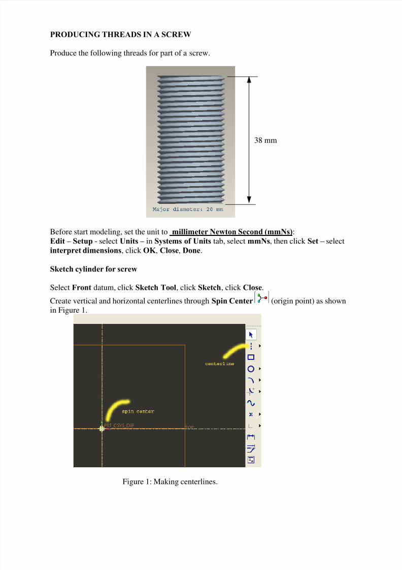
Produce the following threads for part of a screw.
38 mm
Before start modeling, set the unit to millimeter Newton Second (mmNs):
Edit – Setup - select Units – in Systems of Units tab, select mmNs, then click Set – select
interpret dimensions, click OK , Close, Done.
Sketch cylinder for screw
Select Front datum, click Sketch Tool, click Sketch, click Close.
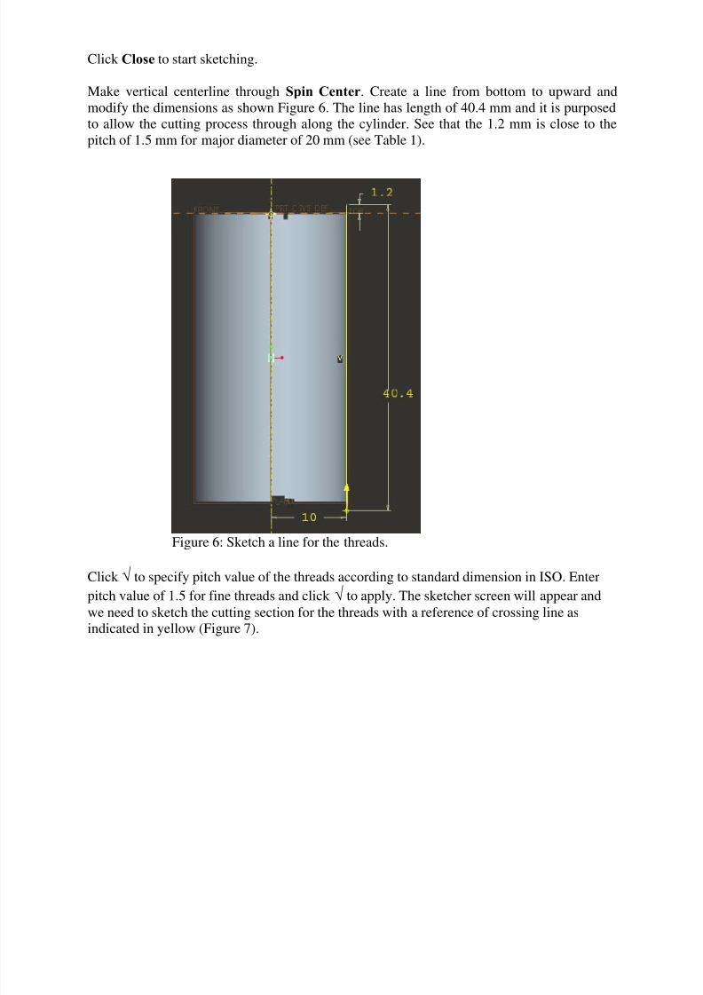
Create vertical and horizontal centerlines through Spin Center (origin point) as shownin Figure 1.
Figure 1: Making centerlines.

8/3/2019 Producing Threads in a Screw
http://slidepdf.com/reader/full/producing-threads-in-a-screw 2/7
Sketch a rectangle and set the dimensions as shown in Figure 2.
Figure 2: Sketch rectangle.
Exit from sketcher by clicking √ (tick) icon. Click Save View List and select Standard
Orientation as shown in Figure 3.
Figure 3: Save view list.

8/3/2019 Producing Threads in a Screw
http://slidepdf.com/reader/full/producing-threads-in-a-screw 3/7
Revolve the section to generate cylinder (Figure 4) using Revolve Tool and click √ to
confirm/ apply.
Figure 4: Cylinder for screw.
Making Threads in Screw
Click Insert – Helical Sweep – Cut, then Menu Manager appears as
Figure 5: Menu Manager for setting up of sketching.
Click Done (Figure 5), select Front datum for sketching plane. Click Okay and then select
Default.
8/3/2019 Producing Threads in a Screw
http://slidepdf.com/reader/full/producing-threads-in-a-screw 4/7

8/3/2019 Producing Threads in a Screw
http://slidepdf.com/reader/full/producing-threads-in-a-screw 5/7
Figure 7: Reference point for cutting section.
Please Zoom In the region around the reference point as indicated in Figure 7 to have the
following screen as
Figure 8: Reference point after zooming in.
Create horizontal and vertical centerlines through the reference point shown in Figure 8.
Then create another vertical centerline on the right hand side of the reference point and next,
create two horizontal centerlines underneath the reference point. Create two (2) slanted
centerlines through the reference point and point A as shown in Figure 9. Modify the
dimensions according to the specified dimensions shown in Figure 9. The dimensions are
corresponding to the standard sizes in ISO.
8/3/2019 Producing Threads in a Screw
http://slidepdf.com/reader/full/producing-threads-in-a-screw 6/7
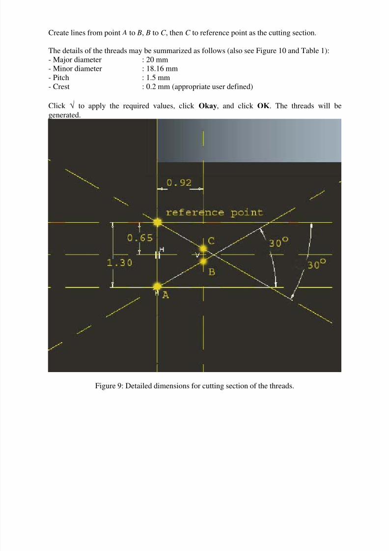
Create lines from point A to B, B to C , then C to reference point as the cutting section.
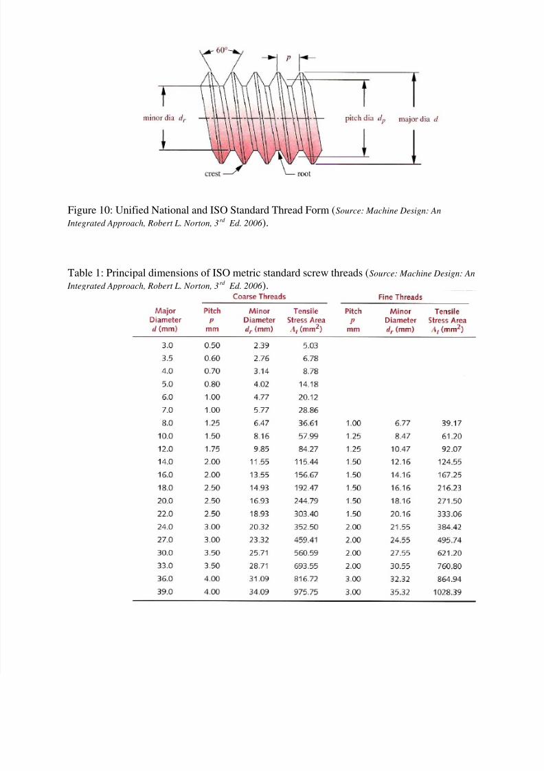
The details of the threads may be summarized as follows (also see Figure 10 and Table 1):
- Major diameter : 20 mm
- Minor diameter : 18.16 mm
- Pitch : 1.5 mm
- Crest : 0.2 mm (appropriate user defined)
Click √ to apply the required values, click Okay, and click OK . The threads will be
generated.
Figure 9: Detailed dimensions for cutting section of the threads.
8/3/2019 Producing Threads in a Screw
http://slidepdf.com/reader/full/producing-threads-in-a-screw 7/7