processor implementation
TRANSCRIPT

Processor Implementation
Overview
• Start with common datapath design concepts
• Simple processor implementation
• Move to more complex implementation
• Finally, pipelined implementation
We'll look at how modern hardware works:
• Clocking, combinational logic, etc
• Pipelining• Dealing with complexity
a.k.a. how do they build those 10 million transistor chips??
Designing Complex FSMs
How many states do we need for a MIPS CPU?
• MIPS has 32 32-bit registers
• Each register could be in one of 232 states
• We need at least 31× 232 states!(register 0 is 0)
... so we clearly don't want to draw the FSM or writethe truth-table!
Idea: exploit FSM structure
Datapath Concepts
Datapath:
• Part of an architecture that manipulates data
• Tends to be �regular�
Example: ALU, MUX, etc.
Control:
• Tells datapath what to do
Example: alu opcode, MUX select input, etc.
Datapath Design
Steps in designing a processor:(or any other piece of hardware)
• Start with high-level speci�cationprocessor: the ISA
• Identify major storage elements and signalsprocessor: registers, memory, ...
• Translate speci�cationdetermine operations on storage elements(RTL, register transfer language)
Datapath Design
More steps...
• Pick computation blocksprocessor: alu
• Determine connectionsdata-dependencies among different blocksi.e., the datapath
• Determine control inputs to datapath blocks
... and then put everything together.
Cross-cutting issue: clocking strategywhen do storage elements get updated?
Datapath Design Example
Example: (unsigned integers)
x = 0;
for (i=1; i <= N; i++)
x = x + i;
Here N is an input and we should produce the resultthat is stored in x.
First step: make the speci�cation precise in termsof signals and clocks.

Datapath Design Example
Better speci�cation of I/O behavior:
• Input N arrives on a bus that is 4 bits wide and N
is non-zero
• Output x is 7 bits wide
• Output xdone (1 bit) is set to 1 when the x outputholds the correct data
• xdone stays high for 1 cycle, after which the next N
input is read and the computation proceeds asbefore
• Signals change at the positive edge of the clock
Pick Storage Elements
There is normally a choice here. For our example:
• i: 4 bit storage element
• N: 4 bit storage element
• x: 7 bit storage element
• xdone: 1 bit output signal
Another option: rewrite the loop and eliminate oneof the storage elements!
x = 0;
for (i=N; i >= 1; i--)
x = x + i;
Translate Speci�cation
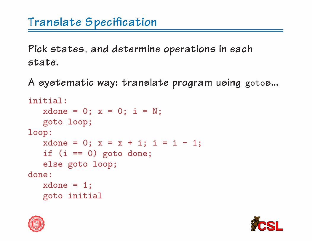
Pick states, and determine operations in eachstate.
A systematic way: translate program using gotos...
initial:xdone = 0; x = 0; i = N;goto loop;
loop:xdone = 0; x = x + i; i = i - 1;if (i == 0) goto done;else goto loop;
done:xdone = 1;goto initial
Translate Speci�cation
Idea:
• Each label is a state
• Advance from one state to the next every cycle
• End of program fragment at each label is a goto
all paths lead to a goto!no intervening labels
RTL: normally uses �<-� for assignment
What about Concurrency?
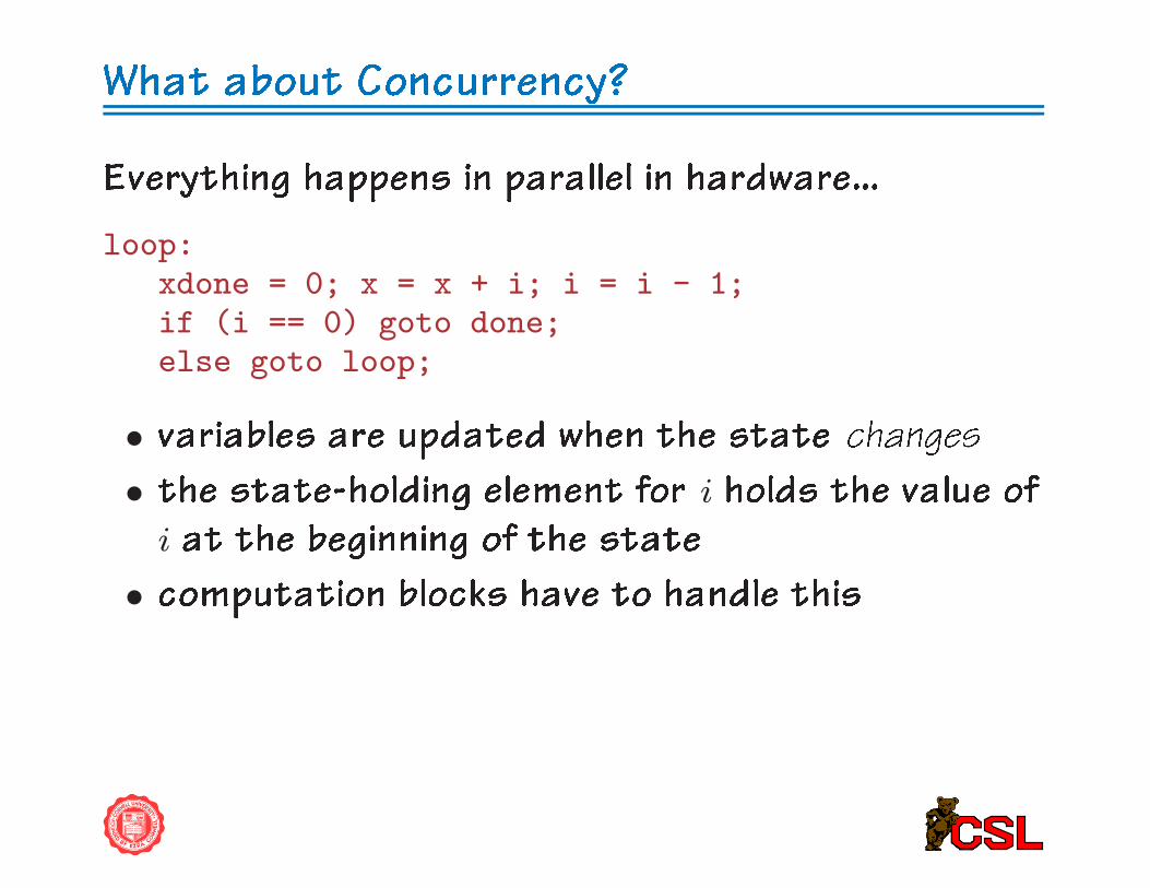
Everything happens in parallel in hardware...
loop:xdone = 0; x = x + i; i = i - 1;if (i == 0) goto done;else goto loop;
• variables are updated when the state changes
• the state-holding element for i holds the value ofi at the beginning of the state
• computation blocks have to handle this
Computation Blocks
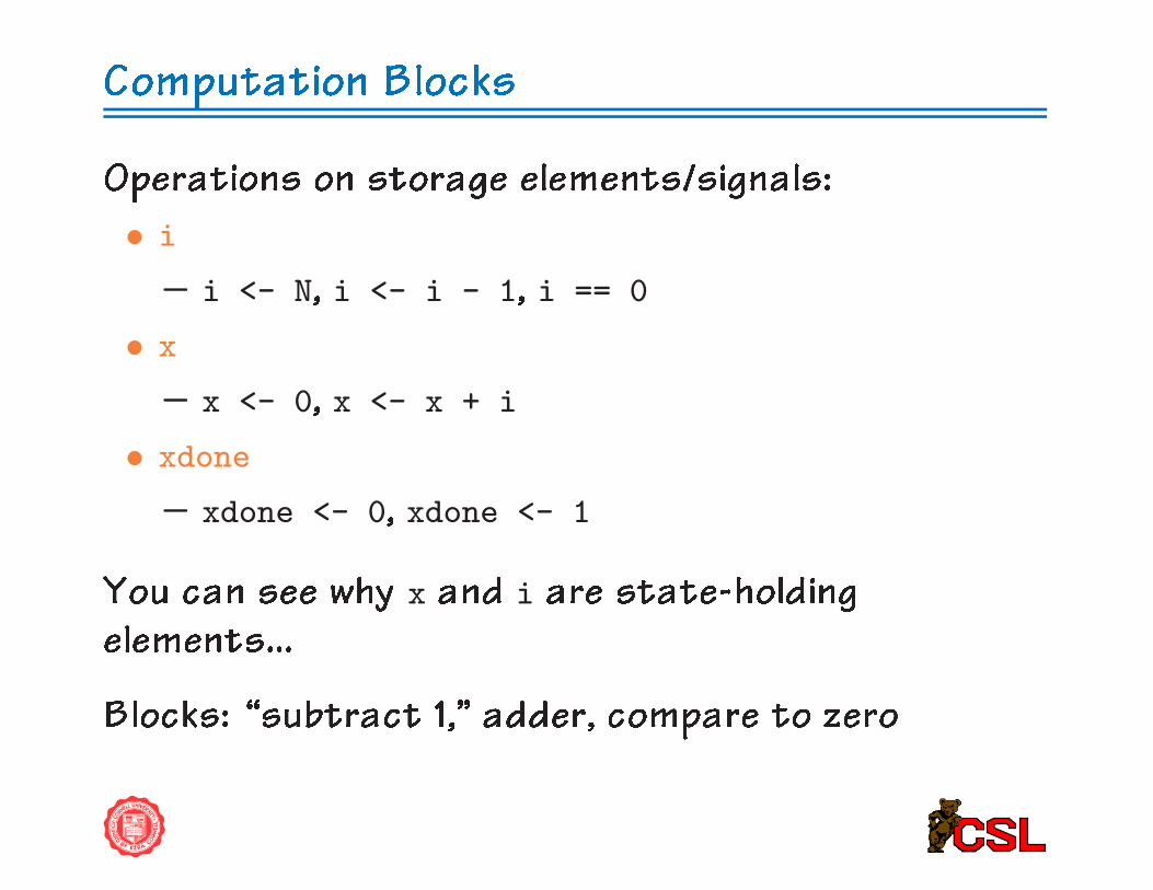
Operations on storage elements/signals:
• i
– i <- N, i <- i - 1, i == 0
• x
– x <- 0, x <- x + i
• xdone
– xdone <- 0, xdone <- 1
You can see why x and i are state-holdingelements...
Blocks: �subtract 1,� adder, compare to zero

Computation Blocks
1
ALU7 bit 4 bit
ALU
4 b
it z
ero
ch
eck
7
7
7
4
4
4 4
or...1 (underflow/carry−out)
7
7 44
sub1
4 bit
4
4/7 bit
adder
Reduce, reuse, recycle...

Data Dependencies
For each storage element, �nd dependencies.
• i
– set to N, output of sub1 block
– used by sub1 block, adder
• x
– set to 0, output of adder
– used by adder
(In general case, determine how computation blocksare interconnected too.)
What is the data �ow?
Data Dependencies
red: write control
7
4
74/7 bit
adder
1
44
sub1
4 bit
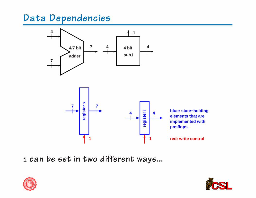
blue: state−holdingelements that are implemented withposflops.
44
regi
ster
i1
7 7
1
regi
ster
x
i can be set in two different ways...
Data Dependencies
red: control
7
4
74/7 bit
adder
1
44
sub1
4 bit
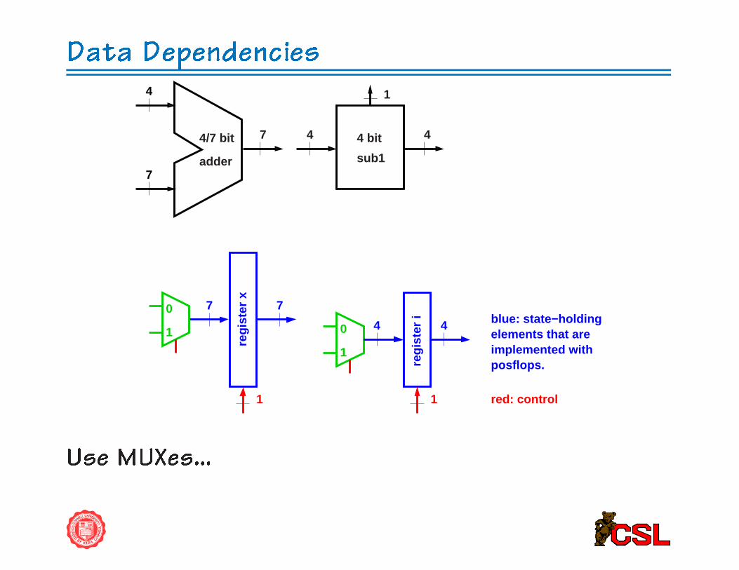
blue: state−holdingelements that are implemented withposflops.
1
0 44
regi
ster
i1
7 7
1
regi
ster
x
1
0
Use MUXes...

Data Dependencies
red: control
N
7
4
74/7 bit
adder
1
44
sub1
4 bit
blue: state−holdingelements that are implemented withposflops.
1
0 44
regi
ster
i1
7 7
1
regi
ster
x
1
0
Connections for i.

Data Dependencies
red: control
0N
7
4
74/7 bit
adder
1
44
sub1
4 bit
blue: state−holdingelements that are implemented withposflops.
1
0 44
regi
ster
i1
7 7
1
regi
ster
x
1
0
Connections for x.

Data Dependencies
xmux
xwrite
imux
7
4
74/7 bit
adder
1
44
sub1
4 bit
blue: state−holdingelements that are implemented withposflops.
1
0 44
regi
ster
i1
7 7
1
regi
ster
x
1
0
0
red: control
N
izero
iwrite
Finally: control
Control
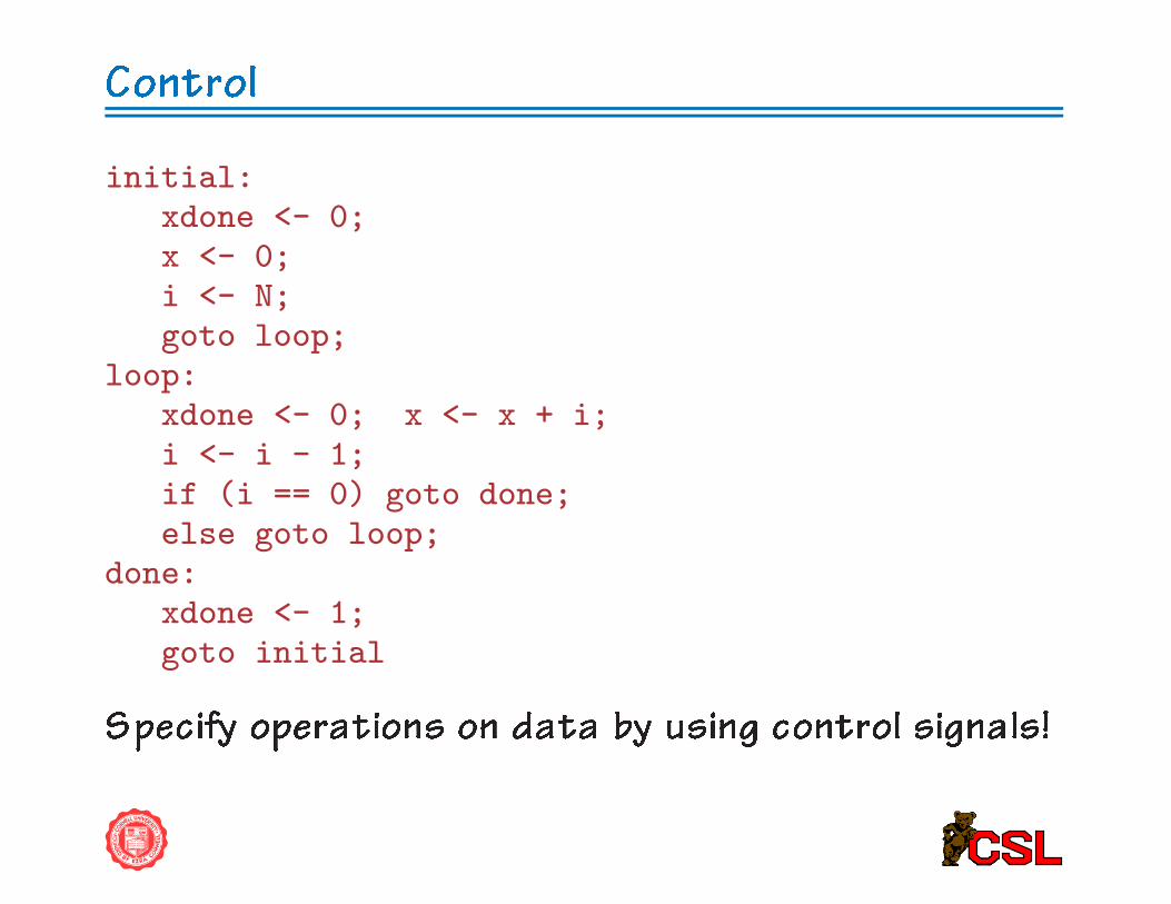
initial:xdone <- 0;x <- 0;i <- N;goto loop;
loop:xdone <- 0; x <- x + i;i <- i - 1;if (i == 0) goto done;else goto loop;
done:xdone <- 1;goto initial
Specify operations on data by using control signals!
Control
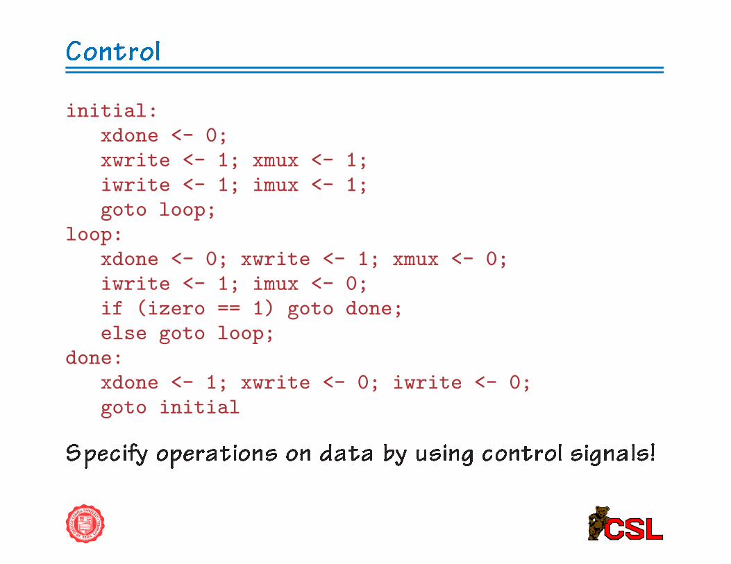
initial:xdone <- 0;xwrite <- 1; xmux <- 1;iwrite <- 1; imux <- 1;goto loop;
loop:xdone <- 0; xwrite <- 1; xmux <- 0;iwrite <- 1; imux <- 0;if (izero == 1) goto done;else goto loop;
done:xdone <- 1; xwrite <- 0; iwrite <- 0;goto initial
Specify operations on data by using control signals!

Control
Important points:
• What about xmux, imux in the done state?⇒ iwrite, xwrite are 0, so don't cares.
• Note: each signal is set in each state!⇒ we can generate them using combinationallogic!
• If this is not the case, need a state-holding
element to remember what the old value of thevariable was...(sometimes referred to as an implied �op/latch)
Control
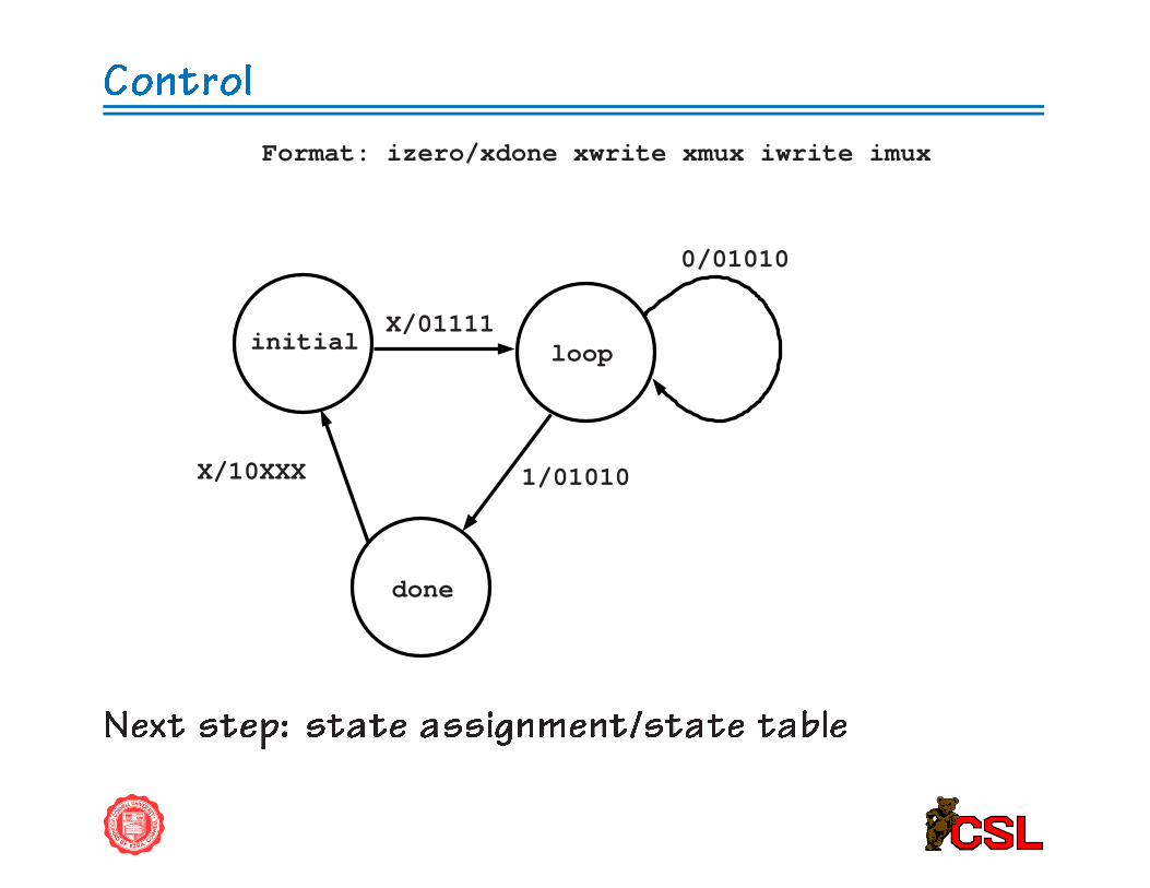
X/10XXX
initial loop
done
Format: izero/xdone xwrite xmux iwrite imux
X/01111
0/01010
1/01010
Next step: state assignment/state table

Control
s0 s1
initial loop
done
Format: izero/xdone xwrite xmux iwrite imux
X/01111
0/01010
1/01010X/10XXX
00 01
10
Next: state tables, logic design
Control
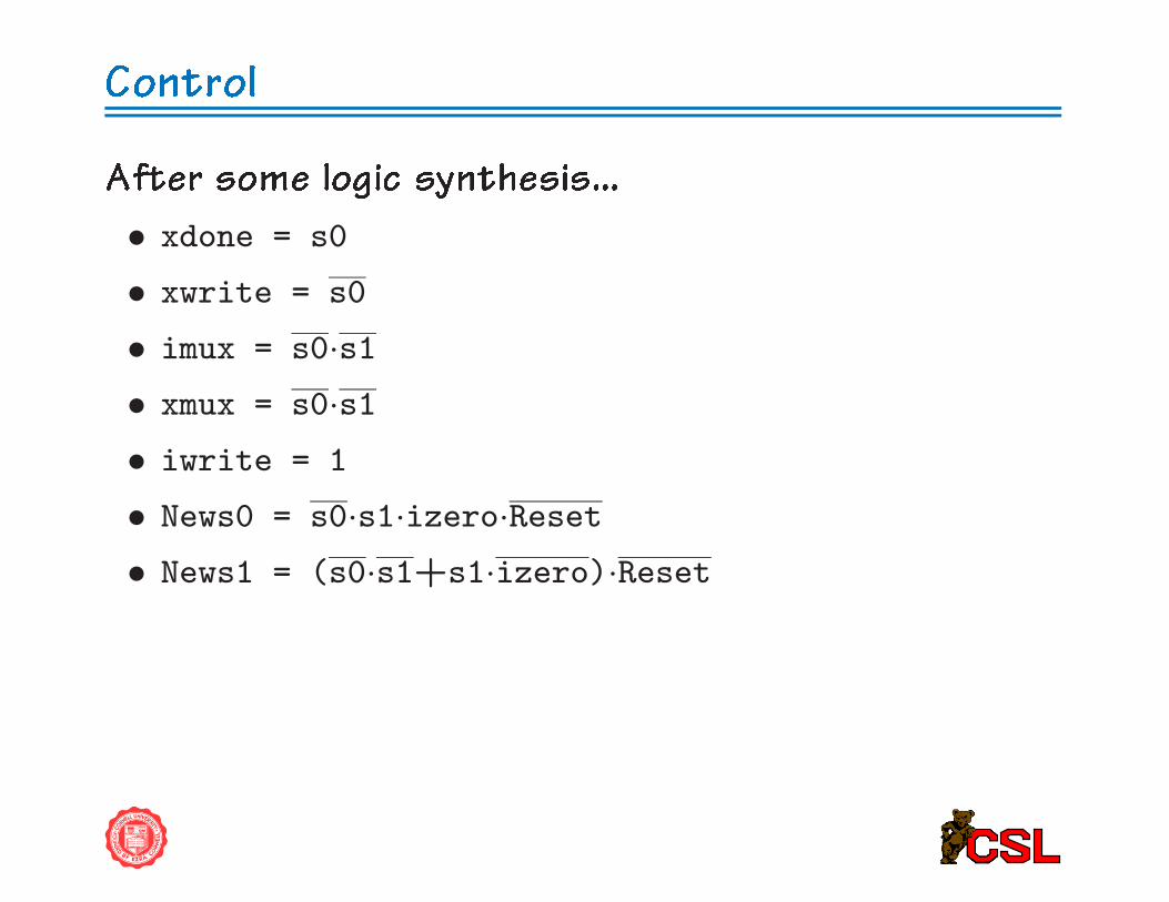
After some logic synthesis...
• xdone = s0
• xwrite = s0
• imux = s0·s1• xmux = s0·s1• iwrite = 1
• News0 = s0·s1·izero·Reset• News1 = (s0·s1+s1·izero)·Reset