process simulations of post-combustion co2 capture...
TRANSCRIPT
I
Pna
WTa
b
c
d
e
a
ARRAA
KPSPPP
1
CpaCaePtpe
h1
ARTICLE IN PRESSG ModelJGGC-2085; No. of Pages 14
International Journal of Greenhouse Gas Control xxx (2016) xxx–xxx
Contents lists available at ScienceDirect
International Journal of Greenhouse Gas Control
j ourna l h o mepage: www.elsev ier .com/ locate / i jggc
rocess simulations of post-combustion CO2 capture for coal andatural gas-fired power plants using a polyethyleneimine/silicadsorbent
enbin Zhang a, Chenggong Sun a, Colin E. Snape a, Robin Irons b, Simon Stebbing c,ony Alderson d, David Fitzgerald e, Hao Liu a,∗
Faculty of Engineering, University of Nottingham, University Park, Nottingham NG7 2RD, UKUniper Technologies Limited, Technology Centre, Ratcliffe on Soar, Nottingham, NG11 0EE, UKPQ Silicas UK Limited, Bank Quay, 4 Liverpool Road, Warrington, Cheshire, WA5 1AB, UKWSP | Parsons Brinckerhoff, Units 4 & 5 Ferrybridge Business Park, Ferrybridge, WF11 8NA, UKDoosan Babcock Limited, Porterfield Road, Renfrew, PA4 8DJ, UK
r t i c l e i n f o
rticle history:eceived 12 September 2016eceived in revised form 1 December 2016ccepted 2 December 2016vailable online xxx
eywords:ost-combustion carbon captureolid adsorbent
a b s t r a c t
The regeneration heat for a polyethyleneimine (PEI)/silica adsorbent based carbon capture system isfirst assessed in order to evaluate its effect on the efficiency penalty of a coal or natural gas powerplant. Process simulations are then carried out on the net plant efficiencies for a specific supercritical550 MWe pulverized coal (PC) and a 555 MWe natural gas combined cycle (NGCC) power plant integratedwith a conceptually designed capture system using fluidized beds and PEI/silica adsorbent. A benchmarksystem applying an advanced MEA absorption technology in a NETL report (2010) is used as a referencesystem. Using the conservatively estimated parameters, the net plant efficiency of the PC and NGCC powerplant with the proposed capture system is found to be 1.5% and 0.6% point higher than the reference PC
rocess simulationEI/silicalant efficiency
and NGCC systems, respectively. Sensitivity analysis has revealed that the moisture adsorption, workingcapacity and heat recovery strategies are the most influential parameters to the power plant efficiency.Under an optimal scenario with improvements in increasing the working capacity by 2% points anddecreasing moisture adsorption by 1% point, the plant efficiencies with the proposed capture system are2.7% (PC) and 1.9% (NGCC) points higher than the reference systems.
© 2016 The Authors. Published by Elsevier Ltd. This is an open access article under the CC BY license
. Introduction
CO2 capture and storage (CCS) from large point anthropogenicO2 emission sources, such as coal and natural gas fired powerlants, has been well recognized to be one of the most effectivend near-term measures to mitigate the increasing atmosphericO2 level. Deployment of the CCS technologies can potentially bringpproximately 20% reduction in the overall global greenhouse gasmissions by 2040 in IEA’s 450 Scenario (IEA, 2015; EBTP, 2012).ost-combustion capture is one of the front runners of CO2 captureechnologies for future commercial applications in fossil fuel power
Please cite this article in press as: Zhang, W., et al., Proceand natural gas-fired power plants using a polyethyleneiminhttp://dx.doi.org/10.1016/j.ijggc.2016.12.003
lants, partly due to the fact that it can be easily retrofitted to thexisting power plants.
∗ Corresponding author.E-mail address: [email protected] (H. Liu).
ttp://dx.doi.org/10.1016/j.ijggc.2016.12.003750-5836/© 2016 The Authors. Published by Elsevier Ltd. This is an open access article u
(http://creativecommons.org/licenses/by/4.0/).
The overall energy required to operate a CCS system is the sumof the thermal energy needed to regenerate the solvents/sorbentsand the electrical energy needed to operate pumps, gas blowersor fans. Energy is also required to compress the recovered CO2to the final pressure for transportation and storage. These extraenergy requirements, together with the capital investments of theequipment will induce a significant increase in the cost of elec-tricity (COE), by 70–100% with existing CCS technologies such asaqueous monoethanolamine (MEA) scrubbing (Haszeldine, 2009;NETL, 2010; Mondal et al., 2012; EPA, 2016). A recent analysis onretrofitting CCS to existing coal-fired power plants has shown thatCCS implementation was not economically favourable for thoseplants with efficiencies less than 35% (low heating value (LHV)based, mainly subcritical) (IEA, 2011, 2015). Although natural gasplays an important role in the power generation sector, the CO2
ss simulations of post-combustion CO2 capture for coale/silica adsorbent. Int. J. Greenhouse Gas Control (2016),
capture cost of a natural gas fired power plant is higher than thatof a coal fired power plant (Middleton and Eccles, 2013). The over-all costs associated with a CCS system with post-combustion CO2
nder the CC BY license (http://creativecommons.org/licenses/by/4.0/).

IN PRESSG ModelI
2 f Greenhouse Gas Control xxx (2016) xxx–xxx
cmmte2Meoeapw1Uo2(
sae“awotcAa2A
paacf(ea(S2maiVem
gmacbtfli2bntdEr
Table 1Characteristics and regeneration heat of PEI/silica adsorbent.
Real density (kg/m3) 1400Bulk density (kg/m3) 700Diameter (�m) 250Specific heat Cp,s (kJ/kg K) 1.81Heat of adsorption �Ha (kJ/kgCO2) 2160 (PC), 2000 (NGCC)Temperature difference �T(K) 60Working capacity qw (wt%) 6 (PC), 5 (NGCC)Moisture adsorption fH2O (wt%) 2Recovery ratio ˛ 0.75Recovery ratio ̌ 0.25
ARTICLEJGGC-2085; No. of Pages 14
W. Zhang et al. / International Journal o
apture mainly include capital cost, operating cost, sorbent replace-ent and employee cost, where capital and operating costs are twoajor contributors. Recently, the techno-economic performance of
he MEA-based CO2 capture process has been evaluated by sev-ral researchers using different methodologies (Abu-Zahra et al.,007; Rubin et al., 2013; Raksajati et al., 2013; Zhao et al., 2013a;anzolini et al., 2015; Li et al., 2016). Abu-Zahra et al. (2007)
stimated that the capital expenditure was around 28% while theperational cost relevant to regeneration heat was around 44%,xcluding compression cost. As an example in a techno-economicnalysis (Li et al., 2016), the specific capital investment of theost-combustion capture (PCC) plant using the MEA-based processith a 650 MWe PC power plant was estimated to be 2013 USD
357/kWe, while the CO2 avoided cost for this process was 2013SD 86.4/tCO2. By combining several process improvements, theptimized process has the potential to reduce the capital cost to013 USD1285/kW and the CO2 avoided cost to 2013 USD 75.1/tCO2Li et al., 2016).
Over the past years, the chemical absorption has been sub-tantially improved with the development of novel solvents anddvanced process designs such as flow sheet modifications (Cousinst al., 2011; IEA 2011, 2015; Han et al., 2011; Mondal et al., 2012).Efficiency penalty” is generally regarded as an index for evalu-ting the difference in power plant efficiency between the plantithout CCS and that integrated with CCS. The efficiency penalty
f a coal or natural gas-fired power plant with chemical absorptionechnology has been investigated by numerous researchers usingommercially available software packages such as Spence
®and
spen®
(Strube and Manfrida, 2011; Dave et al., 2011; Khalilpournd Abbas, 2011; Berstad et al., 2011; Sanpasertparnich et al.,010; Stover et al., 2011; Ystad et al., 2012; Liebenthal et al., 2011;mrollahi et al., 2012; Li et al., 2016).
Solid adsorbents have been comprehensively investigated forost-combustion CO2 capture owing to their potentials in fastdsorption and desorption kinetics, high adsorption capacity, reli-ble regenerability and stability and tuneable range of operatingonditions. Reviews on the recent development of solid adsorbentsor post-combustion CO2 capture can be found in Samanta et al.2012), Hedin et al. (2013), Wang et al. (2011, 2014) and Abanadest al. (2015). Among all solid adsorbents, amine-based adsorbentsre regarded as the most advanced and cost-effective materialsBelmabkhout and Sayari, 2009; Drage et al., 2008; Choi et al., 2009;on et al., 2008; Gray et al., 2009; Ebner et al., 2011; Dutcher et al.,015). Despite of numerous investigations on material develop-ent, however, only a few studies have focused on the process
ssessment for solid adsorbent based CCS systems to be integratednto coal or natural gas fired power plants (Chaffee et al., 2007;eneman et al., 2013; Glier and Rubin, 2013; Kim et al., 2014a; Kimt al., 2014b), while most of them were conducted using theoreticalodels.
Process simulation of a coal or natural gas fired power plant inte-rated with a CCS system requires comprehensive knowledge ofany parameters associated with the fuel properties, physical and
dsorption data of the selected adsorbent, flue gas composition andonditions, as well as the specific process design details of adsor-ers and regenerators. The authors of this paper had demonstratedhe performance of a polyethyleneimine (PEI)/silica adsorbent in auidized bed reactor and also proposed a conceptual design of flu-
dized bed adsorber/desorber for air capture purpose (Zhang et al.,014a,b). In the present study, the previously obtained data haveeen incorporated into the process simulations for a coal and aatural gas fired power plant integrated with CCS systems using
Please cite this article in press as: Zhang, W., et al., Proceand natural gas-fired power plants using a polyethyleneiminhttp://dx.doi.org/10.1016/j.ijggc.2016.12.003
he PEI/silica adsorbent. Fluidized bed adsorbers and desorbers areesigned conceptually according to the specific flue gas conditions.fficiency penalties have been evaluated and compared with theeference benchmark CCS system using an advanced MEA absorp-
Recovery ratio � 0.5Regeneration heat Qr (GJ/tCO2) 2.45 (PC), 2.50 (NGCC)
tion technology (NETL, 2010) and another solid sorbent based CCSsystem (Veneman et al., 2013). It is worth noting that most of theparameters adopted in the process simulation of this study arebased on the experimental results obtained with a bubbling flu-idized bed CO2 adsorber/desorber, thermal gravimetric analyzer(TGA) and differential scanning calorimetry (DSC) (Zhang et al.,2014a,b, 2016) and therefore the uncertainties with the processsimulation parameters for the specific PEI/silica adsorbent used inthis study are minimized.
2. Thermal energy requirement for regeneration
The regeneration heat is usually regarded as the most importantcriteria to evaluate different materials and processes and to assesstheir respective performance for applications in commercial-scaleCO2 capture systems. Reducing the required regeneration heat isthe most effective measure to minimize the loss in net plant effi-ciency. According to Goto et al. (2013), an approximate 2% efficiencyimprovement can be expected by reducing the regeneration energyof the capture system by 1 GJ/tCO2.
In principle, the regeneration heat comprises firstly the sensi-ble heat which is necessary to increase the solvent/sorbent from theadsorption temperature to the regeneration temperature in a typi-cal temperature swing adsorption (TSA) process; secondly the heatof adsorption which is needed to overcome the chemical bondingstrength between the adsorbed CO2 and the adsorbent; and thirdlythe latent heat which is required to evaporate the water contentin the solvent or sorbent. The calculation of regeneration heat canthen be expressed as (Zhang et al., 2016):
Qr = 1 − ˛
qwCp,s (Tde − Tad) +
(1 − ˇ
)�Ha + (1 − �)
QvfH2O
qw(1)
where Qr (GJ/tCO2) is the regeneration heat requirement, qw (wt%)is the working capacity of the solvent/sorbent under given work-ing conditions; ˛, ˇ, � are the fractions of heat recovered fromsensible heat, heat of adsorption and vaporization heat, respec-tively, which can be realized through proper process designs; Cp,s(kJ/kg K) is the specific heat capacity of the solvent/sorbent; Tadand Tde (K) are the temperatures of adsorption and desorption pro-cesses respectively; �Ha (kJ/kgCO2) is the absolute value of heatof adsorption; Qv (kJ/kg) is the vaporization heat of water whichequals to 2257.6 kJ/kg under ambient pressure; and fH2O (wt%) is themass fraction of water content that is evaporated in the regenerator.
The solid adsorbent used in this study was synthesised byimpregnating a mass ratio of 40% PEI into an inorganic mesoporoussilica support (Drage et al., 2008). The PEI has a molecular weight(MW) of 1800 in hyperbranched forms supplied by Sigma–Aldrich,UK. Characterization of the PEI/silica adsorbent by TGA, NMR,
ss simulations of post-combustion CO2 capture for coale/silica adsorbent. Int. J. Greenhouse Gas Control (2016),
DRIFT, XPS and fluidized bed can be found in previous publications(Drage et al., 2008; Zhang et al., 2014a,b). Detailed parametric anal-ysis on all the parameters in Eq. (1) can be found in Zhang et al.(2016) and the main results are summarized in Table 1.
ING ModelI
f Gree
a(iCdbmpteTtbrsacc6soedwTsCoe
oPrtSatertTttrh
3N
3
isccflcfl(ccs
ARTICLEJGGC-2085; No. of Pages 14
W. Zhang et al. / International Journal o
The DSC testing results have shown that the value of heat ofdsorption is dependent on the CO2 partial pressure in the flue gasZhang et al., 2016). The heat of adsorption for the PC case (15% CO2)s 2160 kJ/kgCO2 which is slightly higher than the NGCC case (5%O2) of 2000 kJ/kgCO2. The process dependant working capacity isifferent from the equilibrium capacity which can be determinedy TGA, fixed bed or batch-type fluidized bed tests under isother-al conditions. In a practical regeneration process, pure CO2 or
ure steam or a mixture of CO2 and steam will have to be used ashe sweep gas in order to get high purity product gas of CO2. How-ver this may cause an incomplete desorption comparing with mostGA, fixed bed and batch-type fluidized bed tests using pure N2 ashe sweep gas. Secondly, the solid residence time in practical adsor-er and desorber reactors is much shorter than the time taken toeach the equilibrium condition. Therefore breakthrough capacityhould be used as the working capacity. Finally, the circulating soliddsorbent particles are most likely partially degraded after manyycles even with a constant replacement rate. Based on the aboveonsiderations, the working capacities in this study are adopted as
wt% for the PC case and 5 wt% for the NGCC case, which are bothubstantially lower than the equilibrium capacities demonstratedn previous TGA and cyclic batch-type fluidized bed tests (Zhangt al., 2014b). The moisture adsorption of 2wt% was experimentallyetermined for the PEI/silica adsorbent in a modified TGA systemhich can generate a certain level of moisture with the carrier gas.
he adsorption capacity of the moisture was obtained in the pre-aturation test of moisture followed by the co-adsorption of bothO2 and moisture at the adsorption temperature of 70 ◦C. Detailsf the experimental procedures and results can be found in Zhangt al. (2016).
By substituting the parameters listed in Table 1 into Eq. (1),ne can calculate the regeneration heats to be 2.45 GJ/tCO2 for theC case and 2.50 GJ/tCO2 for the NGCC case. For comparison, theegeneration heat for a typical aqueous 30% MEA CO2 capture sys-em is around 3.90 GJ/tCO2 (Chapel et al., 1999; Alie et al., 2005;ingh et al., 2003; Sjostrom and Krutka, 2010), whereas for thedvanced MEA system with the optimized process configurations,he regeneration heat is about 3.30 GJ/tCO2 (IEA, 2011; Abu-Zahrat al., 2007; Veneman et al., 2013). It should be noted that theegeneration heat calculated by Eq. (1) is purely on the basis ofhermodynamic energy balance using the nominated parameters inable 1 without considering any specific process and devices. Dueo the lack of literature data, the largest uncertainties come fromhe adopted heat recovery ratios. For simplicity, these ratios wereepresented as the effective reductions in the required regenerationeat (Zhang et al., 2016).
. Conceptual design of CO2 capture systems for PC andGCC power plants
.1. Process description
One of the main advantages of post-combustion carbon captures that the capture plant is dealing with the flue gas so that the CCSystem can be retrofitted to existing power plants without signifi-ant modifications to the current configurations. The capture plantan be located at the end of process chain, normally between theue gas treatment devices and the stack. We assume here that theoncentrations of contaminants (e.g. NOx, SO2) after the existingue gas treatment facilities such as selective catalytic reduction
Please cite this article in press as: Zhang, W., et al., Proceand natural gas-fired power plants using a polyethyleneiminhttp://dx.doi.org/10.1016/j.ijggc.2016.12.003
SCR), particle matter remover and flue gas desulphurization (FGD)an also meet the requirements of the adsorbent and process in aarbon capture plant so that no additional flue gas polishing mea-ures are needed.
PRESSnhouse Gas Control xxx (2016) xxx–xxx 3
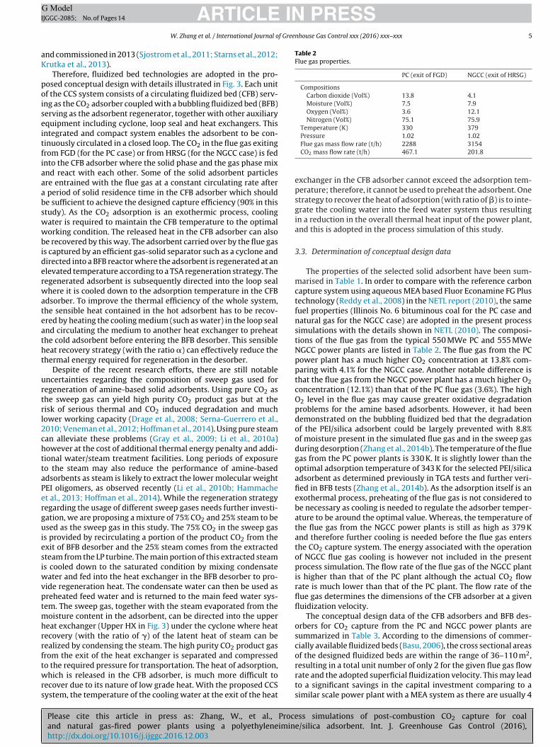
Fig. 1 illustrates the block flow diagram (BFD) of the conceptualflow sheet of a typical 550 MWe supercritical PC fired power plantintegrated with a solid adsorbent based CCS system (adapted fromNETL, 2010). After the flue gas passes FGD where SO2 removal iscarried out, it is directed into the CCS system instead of entering thestack directly as for the case of a power plant without CO2 capture.Each unit of the CCS system consists of an adsorber where CO2in the flue gas is adsorbed by the solid adsorbent together witha desorber where the adsorbent is regenerated under controlledconditions. The cyclone is used to capture the entrained adsorbentfrom the adsorber while the CO2 free flue gas exits from the top ofthe cyclone and is released to the atmosphere through the stack.The high purity CO2 product gas from the exit of the desorber iscompressed and sent to storage.
The regeneration heat required can be provided by steam con-densation via an in-bed heat exchanger (HX). One option for thesteam supply is to integrate the original plant steam and feed watercycle with the capture plant by extracting the superheated steamfrom the low pressure (LP) crossover pipe. After heat exchangein the desorber, the steam is condensed as feed water and thenreturned to the main feed water system. Due to the extractionof steam from the LP turbine, the actual gross power output hasbeen reduced, leading to lower plant efficiency. Using a dedicatedboiler to provide steam to the capture plant is another option whichrequires minimal changes to the original power plant. In this case,the flue gas generated by the dedicated boiler containing CO2 willhave to be re-directed to the capture plant if a high overall CO2capture ratio (e.g. 90%) is to be maintained. The overall plant effi-ciency with this option is however lower than that of the plantwith steam extraction as the extra thermal energy input to thededicated boiler does not generate any power (Popa et al., 2011;Bashadi, 2010). Therefore, the option with steam extraction fromLP turbine is adopted in this study.
The configuration of the CCS system integrated with a NGCCpower plant for post-combustion capture is similar to that of a coal-fired power plant with the CCS system. Fig. 2 illustrates the blockflow diagram of a typical 555 MWe NGCC power plant retrofittedwith a solid adsorbent based CCS system (adapted from NETL,2010). The flue gas exits from the heat recovery steam generator(HRSG) and enters the CCS system where CO2 is captured and theadsorbent is regenerated. Depending on the working temperatureof the selected adsorbent, additional cooling may be required forthe flue gas before entering the CCS system but this is not includedin the process simulation of this study.
3.2. Conceptual design of fluidized beds for CO2 capture
Proficient solid handling and particle technologies are essen-tial to circulate the solid adsorbent particles at a certain rate in aclosed loop. The type of gas-solid contactor has considerable impor-tance in determining the overall working performance of a specificsolid adsorbent. Fluidized beds have been widely used in differentindustrial applications, mainly due to their high gas-solid contactefficiency and high mass/heat transfer rates. Recently, the applica-tion of fluidized bed reactors as the adsorber or regenerator for CO2capture with solid adsorbents has also received noticeable atten-tion. Yang and Hoffman (2009) had proposed a moving bed as aregenerator but finally concluded that the moving bed was notpromising due to poor heat transfer. ADA environmental solutionshad made a survey on four main processes including entrained flow,moving bed, trickle down reactor and fluidized bed and concludedthat the fluidized bed was the most reliable and cost-effective reac-
ss simulations of post-combustion CO2 capture for coale/silica adsorbent. Int. J. Greenhouse Gas Control (2016),
tor option for the solid sorbent based CCS system (ADA, 2010).Continuous CO2 capture was recently demonstrated by using sil-ica supported sorbents impregnated with tetraethylenepentamine(TEPA) in a lab scale fluidized bed to produce a high purity (90%) of

ARTICLE IN PRESSG ModelIJGGC-2085; No. of Pages 14
4 W. Zhang et al. / International Journal of Greenhouse Gas Control xxx (2016) xxx–xxx
Fig. 1. Block Flow Diagram of a PC power plant with CO2 capture.Source: adapted from NETL (2010).
NGCCS
Csbibe
Fig. 2. Block Flow Diagram of aource: adapted from NETL (2010).
O2 product gas (Veneman et al., 2012). By use of theoretical analy-is, Pirngruber et al. (2013) found that the performance of both fixed
Please cite this article in press as: Zhang, W., et al., Proceand natural gas-fired power plants using a polyethyleneiminhttp://dx.doi.org/10.1016/j.ijggc.2016.12.003
ed and fluidized bed processes improved when operated undersothermal conditions which are more difficult to achieve for a fixeded as the heat transfer is much slower than in a fluidized bed. Kimt al. (2014b) proposed a solid sorbent-based multi-stage fluidized
power plant with CO2 capture.
bed process with inter-stage heat integration and used a flow-sheetsimulation to assess the energy efficiency of the system. The fea-
ss simulations of post-combustion CO2 capture for coale/silica adsorbent. Int. J. Greenhouse Gas Control (2016),
sibility of using a three-staged circulating fluidized bed as the CO2adsorber and a single bubbling fluidized bed as the regenerator isbeing demonstrated on a 1 MWe solid sorbent PCC pilot facility at acoal fired power plant in Birmingham, USA which was constructed
IN PRESSG ModelI
f Greenhouse Gas Control xxx (2016) xxx–xxx 5
aK
poiseitfiaaabswwbiderwateatht
urtrl2chttaPerguiesiwvptmhrrftwrs
Table 2Flue gas properties.
PC (exit of FGD) NGCC (exit of HRSG)
CompositionsCarbon dioxide (Vol%) 13.8 4.1Moisture (Vol%) 7.5 7.9Oxygen (Vol%) 3.6 12.1Nitrogen (Vol%) 75.1 75.9
Temperature (K) 330 379Pressure 1.02 1.02
ARTICLEJGGC-2085; No. of Pages 14
W. Zhang et al. / International Journal o
nd commissioned in 2013 (Sjostrom et al., 2011; Starns et al., 2012;rutka et al., 2013).
Therefore, fluidized bed technologies are adopted in the pro-osed conceptual design with details illustrated in Fig. 3. Each unitf the CCS system consists of a circulating fluidized bed (CFB) serv-
ng as the CO2 adsorber coupled with a bubbling fluidized bed (BFB)erving as the adsorbent regenerator, together with other auxiliaryquipment including cyclone, loop seal and heat exchangers. Thisntegrated and compact system enables the adsorbent to be con-inuously circulated in a closed loop. The CO2 in the flue gas exitingrom FGD (for the PC case) or from HRSG (for the NGCC case) is fednto the CFB adsorber where the solid phase and the gas phase mixnd react with each other. Some of the solid adsorbent particlesre entrained with the flue gas at a constant circulating rate after
period of solid residence time in the CFB adsorber which shoulde sufficient to achieve the designed capture efficiency (90% in thistudy). As the CO2 adsorption is an exothermic process, coolingater is required to maintain the CFB temperature to the optimalorking condition. The released heat in the CFB adsorber can also
e recovered by this way. The adsorbent carried over by the flue gass captured by an efficient gas-solid separator such as a cyclone andirected into a BFB reactor where the adsorbent is regenerated at anlevated temperature according to a TSA regeneration strategy. Theegenerated adsorbent is subsequently directed into the loop sealhere it is cooled down to the adsorption temperature in the CFB
dsorber. To improve the thermal efficiency of the whole system,he sensible heat contained in the hot adsorbent has to be recov-red by heating the cooling medium (such as water) in the loop sealnd circulating the medium to another heat exchanger to preheathe cold adsorbent before entering the BFB desorber. This sensibleeat recovery strategy (with the ratio �) can effectively reduce thehermal energy required for regeneration in the desorber.
Despite of the recent research efforts, there are still notablencertainties regarding the composition of sweep gas used foregeneration of amine-based solid adsorbents. Using pure CO2 ashe sweep gas can yield high purity CO2 product gas but at theisk of serious thermal and CO2 induced degradation and muchower working capacity (Drage et al., 2008; Serna-Guerrero et al.,010; Veneman et al., 2012; Hoffman et al., 2014). Using pure steaman alleviate these problems (Gray et al., 2009; Li et al., 2010a)owever at the cost of additional thermal energy penalty and addi-ional water/steam treatment facilities. Long periods of exposureo the steam may also reduce the performance of amine-baseddsorbents as steam is likely to extract the lower molecular weightEI oligomers, as observed recently (Li et al., 2010b; Hammachet al., 2013; Hoffman et al., 2014). While the regeneration strategyegarding the usage of different sweep gases needs further investi-ation, we are proposing a mixture of 75% CO2 and 25% steam to besed as the sweep gas in this study. The 75% CO2 in the sweep gas
s provided by recirculating a portion of the product CO2 from thexit of BFB desorber and the 25% steam comes from the extractedteam from the LP turbine. The main portion of this extracted steams cooled down to the saturated condition by mixing condensate
ater and fed into the heat exchanger in the BFB desorber to pro-ide regeneration heat. The condensate water can then be used asreheated feed water and is returned to the main feed water sys-em. The sweep gas, together with the steam evaporated from the
oisture content in the adsorbent, can be directed into the uppereat exchanger (Upper HX in Fig. 3) under the cyclone where heatecovery (with the ratio of �) of the latent heat of steam can beealized by condensing the steam. The high purity CO2 product gasrom the exit of the heat exchanger is separated and compressed
Please cite this article in press as: Zhang, W., et al., Proceand natural gas-fired power plants using a polyethyleneiminhttp://dx.doi.org/10.1016/j.ijggc.2016.12.003
o the required pressure for transportation. The heat of adsorption,hich is released in the CFB adsorber, is much more difficult to
ecover due to its nature of low grade heat. With the proposed CCSystem, the temperature of the cooling water at the exit of the heat
Flue gas mass flow rate (t/h) 2288 3154CO2 mass flow rate (t/h) 467.1 201.8
exchanger in the CFB adsorber cannot exceed the adsorption tem-perature; therefore, it cannot be used to preheat the adsorbent. Onestrategy to recover the heat of adsorption (with ratio of �) is to inte-grate the cooling water into the feed water system thus resultingin a reduction in the overall thermal heat input of the power plant,and this is adopted in the process simulation of this study.
3.3. Determination of conceptual design data
The properties of the selected solid adsorbent have been sum-marised in Table 1. In order to compare with the reference carboncapture system using aqueous MEA based Fluor Econamine FG Plustechnology (Reddy et al., 2008) in the NETL report (2010), the samefuel properties (Illinois No. 6 bituminous coal for the PC case andnatural gas for the NGCC case) are adopted in the present processsimulations with the details shown in NETL (2010). The composi-tions of the flue gas from the typical 550 MWe PC and 555 MWeNGCC power plants are listed in Table 2. The flue gas from the PCpower plant has a much higher CO2 concentration at 13.8% com-paring with 4.1% for the NGCC case. Another notable difference isthat the flue gas from the NGCC power plant has a much higher O2concentration (12.1%) than that of the PC flue gas (3.6%). The highO2 level in the flue gas may cause greater oxidative degradationproblems for the amine based adsorbents. However, it had beendemonstrated on the bubbling fluidized bed that the degradationof the PEI/silica adsorbent could be largely prevented with 8.8%of moisture present in the simulated flue gas and in the sweep gasduring desorption (Zhang et al., 2014b). The temperature of the fluegas from the PC power plants is 330 K. It is slightly lower than theoptimal adsorption temperature of 343 K for the selected PEI/silicaadsorbent as determined previously in TGA tests and further veri-fied in BFB tests (Zhang et al., 2014b). As the adsorption itself is anexothermal process, preheating of the flue gas is not considered tobe necessary as cooling is needed to regulate the adsorber temper-ature to be around the optimal value. Whereas, the temperature ofthe flue gas from the NGCC power plants is still as high as 379 Kand therefore further cooling is needed before the flue gas entersthe CO2 capture system. The energy associated with the operationof NGCC flue gas cooling is however not included in the presentprocess simulation. The flow rate of the flue gas of the NGCC plantis higher than that of the PC plant although the actual CO2 flowrate is much lower than that of the PC plant. The flow rate of theflue gas determines the dimensions of the CFB adsorber at a givenfluidization velocity.
The conceptual design data of the CFB adsorbers and BFB des-orbers for CO2 capture from the PC and NGCC power plants aresummarized in Table 3. According to the dimensions of commer-cially available fluidized beds (Basu, 2006), the cross sectional areasof the designed fluidized beds are within the range of 36–110 m2,
ss simulations of post-combustion CO2 capture for coale/silica adsorbent. Int. J. Greenhouse Gas Control (2016),
resulting in a total unit number of only 2 for the given flue gas flowrate and the adopted superficial fluidization velocity. This may leadto a significant savings in the capital investment comparing to asimilar scale power plant with a MEA system as there are usually 4

Please cite this article in press as: Zhang, W., et al., Process simulations of post-combustion CO2 capture for coaland natural gas-fired power plants using a polyethyleneimine/silica adsorbent. Int. J. Greenhouse Gas Control (2016),http://dx.doi.org/10.1016/j.ijggc.2016.12.003
ARTICLE IN PRESSG ModelIJGGC-2085; No. of Pages 14
6 W. Zhang et al. / International Journal of Greenhouse Gas Control xxx (2016) xxx–xxx
Fig. 3. Conceptual design of fluidized bed systems for CO2 capture and adsorbent regeneration.
Table 3Conceptual design data for each unit of adsorber and desorber in the CCS system.
PC Adsorber PC Desorber NGCC Adsorber NGCC Desorber
Number of units required 2 2 2 2Bed temperature (K) 343 403 343 403
Minimum fluidization velocity Umf (m/s) 0.027 0.028 0.026 0.028Terminal velocity Ut (m/s) 1.105 1.087 1.106 1.087Superficial velocity U0 (m/s) 3.87 0.111 3.87 0.111U0/Ut (adsorber) or U0/Umf (desorber) 3.5 4 3.5 4Total actual gas flow rate (m3/s) 278 (flue gas) 7.1 (sweep gas) 434.4 (flue gas) 4.0 (sweep gas)Fluidization regime fast bubbling fast bubblingBed cross-section shape square square square squareCross-section dimension (m × m) 8.5 × 8.5 8 × 8 10.6 × 10.6 6 × 6Bed height (m) 50 26 50 31Solid static bed height (m) 5.9 6.6 2.5 7.8Inventory bed mass (t) 295 295 196 196Required bed pressure drop (bar) 0.43 0.49 0.20 0.56Gas-solid contact time (s) 13 60 13 70CO2 capture rate (%) 90 – 90 –CO2 captured/desorbed in each unit (t/day) 4724 4724 2179 2179Solid circulating rate (kg/s) 911 911 504 504Solid flux rate (kg/m2 s) 12.7 14.2 4.5 14.0Mean solid residence time (min) 5.4 5.4 6.5 6.5Heat exchanged in each unit (MW) 118.1 165.4 50.4 76.6Regeneration heat required (GJ/tCO2) – 3.03 – 3.04
ING ModelI
f Gree
uc
flccwtCsea
aePtetTtioant
tgadedffiaclt
Tdepe(bopi
Q
w
Hhcavtrdppts
ARTICLEJGGC-2085; No. of Pages 14
W. Zhang et al. / International Journal o
nits of CCS systems to meet the demand of the specific capturingapacity (NETL, 2010).
The adsorbent particles in the CFB adsorber are fluidized by theue gas itself with additional fans pressurising the flue gas to over-ome the pressure drop in the gas distributor, bed materials and theyclone. The adsorber is operated in the regime of fast fluidizationith a high superficial velocity to facilitate the mixing and reac-
ions between the adsorbent and the flue gas. The bed height of theFB adsorber is determined by the superficial velocity and the gas-olid contact time which is required to achieve the target of capturefficiency. The cross sectional shapes of the CFB and BFB reactorsre designed as square for the ease of construction.
The capture efficiency is assumed to be 90% in the process designs also used by other researchers (Heesink et al., 2013; Venemant al., 2013; Abu-Zahra et al., 2007; Yang and Hoffman, 2009;irngruber et al., 2013). It had been previously demonstrated onhe bubbling fluidized bed (Zhang et al., 2014b) that the capturefficiency could be as high as 100% within a short gas-solid contactime of 13 s which is also adopted in the present conceptual design.he inventory bed mass is a product of the solid circulating rate andhe mean solid residence time. The solid circulating rate gives anndication of how much used adsorbent is carried over to the des-rber and at the same time how much the regenerated adsorbentre returned to the adsorber. It is determined by how much CO2eeds to be adsorbed in the adsorber and the working capacity ofhe adsorbent.
The high temperature in the desorber is the main driving forceo release the captured CO2 from the adsorbent while the sweepas promotes the desorption process to happen by fluidizing thedsorbent in the desorber. The flow rate of the sweep gas is depen-ent on the chosen fluidization velocity. To minimize the additionalnergy required to drive and heat the sweep gas, the desorbers areesigned to operate in the regime of bubbling fluidization where
our times of minimum fluidization velocity is used as the super-cial velocity. The mean solid residence time in the desorbers isssumed to be the same with that in the adsorbers. The solid cir-ulating rate required for a NGCC case is 504 kg/s, which is muchower than 911 kg/s for a PC case due to the lower CO2 flow rate inhe NGCC power plant flue gas.
The regeneration heats for both PC and NGCC cases listed inable 3 in the specific design are higher than those in Table 1 asifferent recovery strategies for heat of adsorption and differentnergy supplies for regeneration are used. Fig. 4 illustrates two pro-osed options of heat recovery strategies for heat of adsorption andnergy supplies for regeneration. Heat recovery strategy option 1HR1) is defined that the heat of adsorption (Qad) in the CFB adsor-er is recovered (with a ratio of � = 0.25) by preheating a portionf feed water so that the thermal energy input (Qf ) to the powerlant is reduced to Qf − ˇQad. The regeneration heat Qr,0 required
n the BFB desorber is defined as:
r,0 = (1 − ˛)Qs + Qad + (1 − �)Qv (2)
here Qs is the sensible heat requirement.Qr,0 is supplied by the extracted steam from LP turbines in HR1.
eat recovery strategy option 2 (HR2) is defined to recover theeat of adsorption Qad (with a ratio of � = 0.25) by circulating theooling water as the heat transfer medium (HTM) from the CFBdsorber to the BFB desorber. A dedicated boiler is required to pro-ide additional heat to further increase the temperature of HTM tohe desorption temperature. Using HR2 can effectively reduce theequired regeneration heat from Qr,0 to Qr,0 − ˇQad. However, theedicated boiler in HR2 needs extra thermal energy input (Qf ’) and
Please cite this article in press as: Zhang, W., et al., Proceand natural gas-fired power plants using a polyethyleneiminhttp://dx.doi.org/10.1016/j.ijggc.2016.12.003
roduces no additional electricity work which makes the overallower generation efficiency of the power plant with CCS no betterhan the option HR1 where low grade steam is used as the energyupply. More detailed analysis of the overall performance of using
PRESSnhouse Gas Control xxx (2016) xxx–xxx 7
the dedicated boiler as the energy supply can be found in Popa et al.(2011) and Bashadi (2010) and is not within the scope of this study.
Fig. 5 illustrates the breakdown of the regeneration heat orig-inating from the sensible heat, heat of adsorption and moistureevaporation. It is obvious that without any kind of heat recovery( ̨ = ̌ = � = 0), the total regeneration heat for either the PC case(4.79 GJ/tCO2) or the NGCC case (5.15 GJ/tCO2) is much higher thanthe basic MEA case (3.90 GJ/tCO2) and the advanced MEA case(3.30 GJ/tCO2) (NETL, 2010), both of which include 90% of sensi-ble heat recovery. Using HR1 and the specific conceptual designproposed in this study, the total regeneration heat (3.03 GJ/tCO2for the PC case and 3.04 GJ/tCO2 for the NGCC case) is noticeablylower than the basic MEA case and the advanced MEA case. Thetotal regeneration heat can be further reduced to 2.49 GJ/tCO2 forthe PC case and 2.54 GJ/tCO2 for the NGCC case if HR2 is adopted.It can also be found that the heat of adsorption makes the largestcontribution to the total regeneration heat while the recovery ofthis portion of the low grade heat is most practically difficult.
4. Process simulations of power plants integrated with theproposed CO2 capture system
4.1. Efficiency penalty of a power plant with CCS
The net power plant efficiency is the most important and appar-ent factor to assess the economic performance of a power plant withand without the CCS system. For a power plant without CCS, it canbe defined as the percentage of the total thermal energy input ofthe feed fuel that is converted into electricity, as shown in Eq. (3):
� = EeQf
= Eg − EauQf
(3)
where Ee (MWe) is the net power output of the power plant andQf (MWth) is the thermal energy input of the fuel, Eg (MWe) isthe gross power output from turbines and Eau (MWe) is the totalauxiliary load including plant operation and consumption and thetransformer losses. It should be noted that all the values of � andthermal energy input of the fuel in this study are LHV based.
There are two rationales to evaluate the efficiency of a powerplant when a CCS system is integrated.
(i) Ee is fixed to meet the end user demand while increasing thefeeding rate of fuel to compensate for the power output lossincurred by the CCS system. Increasing the fuel feeding ratemay require changing the dimension and capacity of the boileror lead to different steam conditions. Therefore this rationaleis more suitable for a new power plant to be built with CO2capture;
(ii) Qf is fixed while the net power output is re-evaluated when theCO2 capture system is integrated. This rationale is more suitablefor retrofitting an existing power plant to integrate the CCS sys-tem. It is also more applicable for NGCC case as the capacitiesof NGCC power plants are determined by the fixed outputs ofthe commercially available gas turbines.
The PC case with the MEA system in NETL (2010) used rationale(i) while in this study the PC case with the PEI/silica adsorbent basedcapture system uses rationale (ii). Rationale (ii) is used for the NGCCcases in both NETL (2010) and this study.
For the cases where CO2 capture is integrated, the net plantefficiency can be expressed as:
c c c
ss simulations of post-combustion CO2 capture for coale/silica adsorbent. Int. J. Greenhouse Gas Control (2016),
�c = EeQf
= Eg − Eau − Ecap − EcomQf
(4)
where Ecap (MWe) is the electrical energy required for the opera-tion of the CCS system; Ecom (MWe) is the electrical energy required

ARTICLE IN PRESSG ModelIJGGC-2085; No. of Pages 14
8 W. Zhang et al. / International Journal of Greenhouse Gas Control xxx (2016) xxx–xxx
F s for
i
tposw
ig. 4. Options of heat recovery strategies for heat of adsorption and energy supplienput; (b) HR2: heat of adsorption is recovered to reduce the regeneration heat.
o compress the CO2 product gas to the desired pressure for trans-
Please cite this article in press as: Zhang, W., et al., Proceand natural gas-fired power plants using a polyethyleneiminhttp://dx.doi.org/10.1016/j.ijggc.2016.12.003
ortation and storage. Transportation and subsequent storage costsf the CO2 product gas are not considered in this study following theame methodology of the NETL (2010). The gross power output Egc
ith CO2 capture is reduced compared to the original power plant
regeneration (a) HR1: heat of adsorption is recovered to reduce the thermal energy
as the extracted steam from LP turbines is used to provide the ther-
ss simulations of post-combustion CO2 capture for coale/silica adsorbent. Int. J. Greenhouse Gas Control (2016),
mal heat for the regeneration process. The thermal energy input Qfis assumed to be effectively reduced by recovering a portion of heatof adsorption using heat recovery strategy option 1 (HR1).

ARTICLE IN PRESSG ModelIJGGC-2085; No. of Pages 14
W. Zhang et al. / International Journal of Greenhouse Gas Control xxx (2016) xxx–xxx 9
0.0
0.5
1.0
1.5
2.0
2.5
3.0
3.5
4.0
4.5
5.0
5.5
6.0
NGCCwith HR2
PC with HR2
PC with HR1
Reg
ener
atio
n he
at b
reak
dow
n (G
J/tC
O2) Moisture evap oration
Hea t of ad sorptionSensible hea t4.79
3.03
2.49
5.15
3.04
2.54
PC w/o HR
NGCCw/o HR
NGCCwith HR1
Fig. 5. Regeneration heat breakdowns for PC and NGCC capture plants with and without heat recovery (numbers above columns indicate the total regeneration heat for eachcase).
Table 4Steam/water conditions and properties (data shown are for each unit of desorber).
PC NGCC
Saturated steam into BFB desorberPressure (bar) 5.069 5.069Temperature (K) 425.4 425.4Specific enthalpy (kJ/kg) 2748.7 2748.7Mass flow rate in the sweep gas (kg/s) 1.2 0.68Mass flow rate required for regeneration (kg/s) 79.9 37.0
Condensed waterPressure (bar) 9.214 5.069Temperature (K) 424.1 424.1Specific enthalpy (kJ/kg) 637.3 636.8
Extracted steam from LPPressure (bar) 5.069 5.172Temperature (K) 564.3 611.6
td
�
4
tesewAcmtoits
Table 5Turbine power outputs and gross plant power.
PC NGCC
LP turbine power output (MW) 235.6 (w/o)150.7 (CCS)
102.2 (w/o)55.7 (CCS)
IP turbine power output (MW) 172.8 60.4HP turbine power output (MW) 180.7 46.9Total steam turbine power output (MW) 589.1 (w/o)
504.2 (CCS)210.0 (w/o)163 (CCS)
Generator efficiency (%) 98.5 96.6Gas turbine power (MW) – 362.2Gross plant power (MW) 580.3 (w/o) 564.7 (w/o)
Specific enthalpy (kJ/kg) 3046.4 3144.1Mass flow rate extracted for LP turbine (kg/s) 71.1 31.7
The efficiency penalty of a power plant with CCS compared withhe original power plant without CCS can then be defined as theifference in net plant efficiencies:
� = � − �c (5)
.2. Power plant output losses
The conditions and properties of steam and water used inhe proposed capture system are listed in Table 4. The steam isxtracted from the cross-over pipe between the intermediate pres-ure (IP) and LP steam turbine sections. The conditions of thisxtracted superheated steam (pressure, temperature) are the sameith those defined by the reference power plants (NETL, 2010).
portion of the condensed water is recirculated to mix with andool down the superheated steam to the saturation condition. Theain stream of the saturated steam enters the heat exchangers in
he desorber to provide regeneration heat while a small fraction
Please cite this article in press as: Zhang, W., et al., Proceand natural gas-fired power plants using a polyethyleneiminhttp://dx.doi.org/10.1016/j.ijggc.2016.12.003
f the steam is flashed to the lower pressure required for fluidiz-ng adsorbent particles in the BFB desorber and then it is fed intohe BFB desorber together with the recirculated CO2 to serve as theweep gas. Power outputs of different steam turbines are also listed
496.6 (CCS) 519.7 (CCS)Gross plant power loss with CCS (MW) 83.7 46.4
in Table 5. Comparing with the cases without CCS, the integrationof the CO2 capture system has induced a power loss in LP turbinesdue to the extraction of steam. The reduction in gross power outputis 83.7 MW for PC/CCS case and 46.4 MW for NGCC/CCS case.
The breakdown of power losses in Eq. (4), i.e. CO2 compressionpower consumption, capture system auxiliaries’ power consump-tion, LP power output loss resulted from steam extraction and theoriginal plant auxiliaries’ power consumption have been assessedfor PC/CCS and NGCC/CCS cases with the proposed capture systemand compared with the original power plant and the power plantintegrated with the advanced MEA based system (NETL, 2010).As illustrated in Fig. 6, for both PC and NGCC power plants, theproposed CCS system has significantly reduced the power lossesfrom LP turbines, owing to the smaller amount of extracted steamrequired for regeneration of the solid adsorbent comparing withthe reference advanced MEA cases. The calculated capture systemauxiliaries’ load for the proposed CCS system is however slightlyhigher than the advanced MEA system due to the higher demandof electrical energy to drive the fans and circulate the solid adsor-bent within the loop. It can also be concluded from Fig. 6 that allNGCC cases with or without CO2 capture have much lower power
ss simulations of post-combustion CO2 capture for coale/silica adsorbent. Int. J. Greenhouse Gas Control (2016),
losses than the corresponding PC cases. The total power losses forNGCC PEI/silica case are comparable to the NGCC advanced MEAcase. The big difference between the PC advanced MEA case andthe PC PEI case is mostly due to the fact that the PC advanced MEA

ARTICLE IN PRESSG ModelIJGGC-2085; No. of Pages 14
10 W. Zhang et al. / International Journal of Greenhouse Gas Control xxx (2016) xxx–xxx
1 2 3 4 5 60
50
100
150
200
250
300
NGCC PEI
NGCC MEA
NGCC w/o
PC PEI
PC MEA*
Pow
er L
osse
s (M
We)
CO2 compression work
Capture system auxiliariesLP power output lossOriginal plant auxiliaries
PC w/o
Fig. 6. Comparison of power losses for PC and NGCC power plants with and without the CCS system (*PC advanced MEA case uses rationale (i)).
Table 6Simulation results for PC power plants w/o and with CO2 capture.
Power Plant data Spence® simulation by Veneman et al. (2013) NETL (2010) this study
w/o MEA SAS w/o MEAa PEI
Thermal energy input by coal (MWth) 2307.3 2307.3 2307.3 1400.2 1934.5 1321Gross plant power (MWe) 1116.7 935.9 1031.8 580.4 662.8 496.6Plant own consumption (MWe) 45.9 46.0 45.9 28.6 45.1 28.6Transformer losses (MWe) 2.1 1.6 1.8 1.82 2.3 1.6CO2 capture related electricity demand (MWe) – 19.9 22.2 – 20.6 26.4CO2 compression (MWe) – 64.5 72.9 – 44.9 32.2Net plant power (MWe) 1068.6 804.0 889.0 550 550 407.9Net plant efficiency (%) 46.3 34.8 38.5 40.8 29.4 30.9Relative efficiency penalty (%) – 24.8 16.8 – 27.8 24.2Required extra thermal energy input (% of MWth) – 33.0 20.2 – 38.6 32.0
0.11
ca
4
tsoaV
wcwte1b(irS
CO2 emission rate (tCO2/MWh) 0.84
a Net plant power is kept the same as original PC power plant only for this case.
ase in NETL (2010) uses rationale (i) where the fuel feeding rate,s well as the gross power output, has been greatly increased.
.3. Efficiency penalty and comparison with reference data
The net plant efficiencies of PC and NGCC power plants withhe proposed CO2 capture system are assessed and the results areummarized in Table 6 (PC) and Table 7 (NGCC). Simulation resultsf a PC and a NGCC power plant with CO2 capture by MEA scrubbingnd SAS (Supported Amine Sorbents) using Spence
®software by
eneman et al. (2013) are also listed for comparison.The net plant efficiency for the PC power plant integrated
ith the proposed capture system is 30.9% and the absolute effi-iency penalty is 9.9% comparing with the original PC power plantithout CCS. Using the advanced MEA system as the capturing
echnology induces an efficiency penalty of 11.4% according to thestimate by NETL (2010). Zhao et al. (2013a) had also reported a0–14% decrease in the net plant efficiency for the optimized MEA-ased absorption processes. According to a recent literature review
Please cite this article in press as: Zhang, W., et al., Proceand natural gas-fired power plants using a polyethyleneiminhttp://dx.doi.org/10.1016/j.ijggc.2016.12.003
Rubin et al., 2015), the net plant efficiency penalties for supercrit-cal PC plants with advanced post-combustion CCS technologiesange from 7.7 to 11.9%. Whereas, a recent study by Supekar andkerlos (2015) had concluded a much wider range of efficiency
0.11 0.80 0.10 0.11
penalties from 11.3 to 22.9% for retrofitting a 650 MWe subcriticalPC plant with the advanced MEA based CCS system. The higher endof 22.9% was derived under a strict representative scenario withassumptions of 1) there is no heat recovery; 2) steam extractionfrom turbine is not feasible thus a dedicated coal-fired boiler isneeded to supply the regeneration heat; 3) additional devices andassociated energy input are needed for removal of flue gas contam-inants. The uncertainties arising from adopting different scenarioshave led to disputes (Herzog et al., 2016; Supekar and Skerlos,2016). Further assessment of the efficiency penalty is needed toeliminate the uncertainties by developing more advanced pro-cesses and learning experiences from worldwide demonstrationCCS projects.
As the thermal heat input and the net plant power output are dif-ferent for each case, a term of “relative efficiency penalty” is definedas “the ratio between the net efficiency penalty and the originalplant efficiency”. The calculated relative efficiency penalty for theproposed capture system for the PC plant is 24.2%, comparing to27.8% for the advanced MEA system in NETL (2010). For the SAS
ss simulations of post-combustion CO2 capture for coale/silica adsorbent. Int. J. Greenhouse Gas Control (2016),
case in Veneman’s simulation (Veneman et al., 2013), the efficiencypenalty was estimated to be 7.8%, which is lower than the penaltyof the PEI/silica based CCS system investigated in this study (9.9%).The net plant efficiency of the proposed CCS system for the PC case

ARTICLE IN PRESSG ModelIJGGC-2085; No. of Pages 14
W. Zhang et al. / International Journal of Greenhouse Gas Control xxx (2016) xxx–xxx 11
Table 7Simulation results for NGCC power plants w/o and with CO2 capture.
Power Plant data Spence® simulation by Veneman et al. (2013) NETL (2010) this study
w/o MEA SAS w/o MEA PEI
Thermal energy input by natural gas (MWth) 756.7 756.7 756.7 997 997 984.4Gross plant power (MWe) 452.4 408.2 431.1 564.7 511.0 519.7Plant own consumption (MWe) 6.0 5.1 5.6 7.9 11.0 7.9Transformer losses (MWe) 0.9 0.8 0.8 1.7 1.6 1.6CO2 capture related electricity demand (MWe) – 6.0 15.3 – 9.6 21.3CO2 compression (MWe) – 12.1 13.6 – 15.2 15.1Net plant power (MWe) 445.5 384.2 395.8 555 473.6 473.8Net plant efficiency (%) 58.9 50.8 52.3 55.7 47.5 48.1Relative efficiency penalty (%) – 13.8 11.2 – 14.7 13.5Required extra thermal energy input (% of MWth) – 16.0 12.7 – 16.2 15.6CO2 emission rate (tCO2/MWh) 0.37 0.04 0.04 0.36 0.04 0.04
(a) Effect of moisture adsor ption on net plant efficiency (b) Effect of wor king ca pacit y on net plant efficiency
0 2 4 6 8 1026
27
28
29
30
31
32
33
34
Net
pla
nt e
ffici
ency
(%)
moisture ad sorption (w t%)
29.4 (PC MEA)
4 6 8 1026
27
28
29
30
31
32
33
34
Net
pla
nt e
ffici
ency
(%)
working capa city qw (wt%)
29.4 (PC MEA)
0.00 0.25 0.50 0.75 1.0026
27
28
29
30
31
32
33
34
Net
pla
nt e
ffici
ency
(%)
Heat recovery ratio β
29.4 (PC MEA)
(c) Effect of heat recovery ratio β on net plant efficiency (d) Effect of por tion of steam in the swee p gas on net plant efficiency
0 25 50 75 10026
27
28
29
30
31
32
33
34
Net
pla
nt e
ffici
ency
(%)
Portion of stea m in the sweep ga s (vol%)
29.4 (PC MEA)
F ciencc
itbctahht
ig. 7. Sensitivity analysis of the important parameters affecting the net plant effiircle around indicates the value with nominated assumptions listed in Table 1).
n this study is 1.5% (absolute) higher than the advanced MEA sys-em. As mentioned earlier in Section 2, we are using conservativeut more practical assumptions for the adsorbent properties asso-iated with a practical process such as the heat of adsorption andhe working capacities. Our measured data of heat of adsorption
Please cite this article in press as: Zhang, W., et al., Proceand natural gas-fired power plants using a polyethyleneiminhttp://dx.doi.org/10.1016/j.ijggc.2016.12.003
re higher than most of the reported values. The more conservativeowever practical heat recovery strategy (HR1) of recovering theeat of adsorption is also used in this study. These factors have ledo a higher regeneration heat of 3.03 GJ/tCO2 (PC) or 3.04 GJ/tCO2
y for PC power plant integrated with the proposed CCS system (data point with a
(NGCC) comparing with 1.8 GJ/tCO2 estimated by Veneman et al.(2013). The required extra thermal heat input in Tables 6 and 7 iscalculated on the condition that more fuel needs to be consumedin order to maintain the net plant power output to be the same asthat of the original power plant.
ss simulations of post-combustion CO2 capture for coale/silica adsorbent. Int. J. Greenhouse Gas Control (2016),
The net plant efficiency for the NGCC power plant integratedwith the proposed PEI/silica based CCS system is 48.1% and theabsolute efficiency penalty comparing with the original NGCCpower plant without CCS is 7.6%, which represents 0.6% improve-

ARTICLE IN PRESSG ModelIJGGC-2085; No. of Pages 14
12 W. Zhang et al. / International Journal of Greenhouse Gas Control xxx (2016) xxx–xxx
(a) Effect of moisture adsor ption on net plant efficiency
0 2 4 6 8 1044
45
46
47
48
49
50
51N
et p
lant
effi
cien
cy (%
)
moisture ad sorption (wt%)
47.5 (NGCC MEA )
(b) Effect of working capacity on net plant efficiency
(c) Effect of heat recovery ratio β on net plant efficiency
2 3 4 5 6 7 8 9 1044
45
46
47
48
49
50
51
Net
pla
nt e
ffici
ency
(%)
working cap acity qw (wt%)
47.5 (NGCC MEA)
0.00 0.25 0.50 0.75 1.0044
45
46
47
48
49
50
51
Net
pla
nt e
ffici
ency
(%)
Heat recovery ratio β
47.5 (NGCC MEA )
0 25 50 75 10044
45
46
47
48
49
50
51
Net
pla
nt e
ffici
ency
(%)
Portion of stea m in the sweep gas (vol%)
47.5 (NGCC MEA)
(d) Effect of portion of steam in the sweep gas on net plant
efficiency
F iency
c
mstsfftoN
4
escFhtepicf
vafat
ig. 8. Sensitivity analysis of the important parameters affecting the net plant efficircle around indicates the value with nominated assumptions listed in Table 1).
ent in the net plant efficiency comparing with the advanced MEAystem in NETL (2010). By retrofitting CO2 capture facilities withhe target capture efficiency of 90%, the CO2 emission rates haveignificantly reduced from 0.80 to 0.11 tCO2/MWh (PC cases) androm 0.36 to 0.04 tCO2/MWh (NGCC cases). The CO2 emission ratesor NGCC cases are much lower than those for PC cases because ofhe higher heating value of natural gas, the lower carbon intensityf natural gas relative to coal, and the higher overall efficiency ofGCC power plants.
.4. Sensitivity analysis on the net plant efficiency
Due to the lack of investigations on the process-related param-ters associated with a solid adsorbent based CCS system, it istill difficult to give an accurate estimation of the net plant effi-iency considering potential uncertainties involved in this study.rom the parametric analysis of the factors affecting regenerationeat (Zhang et al., 2016), working capacity and moisture adsorp-ion were identified as the two most influential parameters. Theirffects on the net plant efficiencies for both PC and NGCC powerlants with CCS are also evaluated in this study and the results are
llustrated in Fig. 7 (PC) and Fig. 8 (NGCC), where the net plant effi-iency for the advanced MEA based system is used as a referenceor comparison.
Moisture co-adsorption in the CFB adsorber and its subsequentaporization in the BFB desorber have a crucial effect on the over-
Please cite this article in press as: Zhang, W., et al., Proceand natural gas-fired power plants using a polyethyleneiminhttp://dx.doi.org/10.1016/j.ijggc.2016.12.003
ll regeneration heat and the net plant efficiency. However, only aew investigations (Quang et al., 2014; Veneman et al., 2015) haveddressed this issue at the process level. The amount of adsorp-ion, as well as the physical state of the moisture during adsorption
for NGCC power plant integrated with the proposed CCS system (data point with a
and desorption, are still not completely understood. By assumingthat the moisture is adsorbed in liquid state in the adsorber anddesorbed totally in the desorber in vapour state, the effects of mois-ture adsorption capacity on the net plant efficiencies for both PCand NGCC cases have been evaluated as shown in Figs. 7(a) and8(a), respectively. If the moisture adsorption capacity is higher than5 wt% for the PC case or 4 wt% for the NGCC case, the estimated netplant efficiency for the solid adsorbent based CCS systems wouldbe no better than the advanced MEA based system (NETL, 2010).Therefore, the strategies that can restrict the moisture adsorptionin the adsorber or moisture vaporization in the desorber such assurface modifications to enhance the hydrophobicity or control-ling adsorbent residence times in the adsorber and desorber canenhance the advantages of a solid adsorbent based CCS system.
High equilibrium CO2 adsorption capacities have been the maintarget of the recent efforts on material development while theworking capacity of a specific solid adsorbent in a continuousCO2 adsorption system has only been studied by a few groupsof researchers recently (Sjostrom et al., 2011; Zhao et al., 2013b;Breault et al., 2016). Increasing working capacity can reduce therequired solid circulating rate which in turn reduces the requiredregeneration heat, as well as the electrical energy to circulate thesolid adsorbent and therefore the efficiency penalty. Based on theproposed system using the PEI/silica adsorbent, the estimated netplant efficiency becomes lower than the advanced MEA system ifthe working capacity is lower than 4 wt% (Figs. 7(b) and 8(b)), whichmight be regarded as the minimum requirement for a solid adsor-
ss simulations of post-combustion CO2 capture for coale/silica adsorbent. Int. J. Greenhouse Gas Control (2016),
bent based CCS system to be more advantageous than the advancedMEA system. It should also be noted that, as revealed in Figs. 7(b)and 8(b), the parabolic alike curves imply that further improvement

ING ModelI
f Gree
ie
Csrtac2aet
apocptSattacs(p
tsNfumsi(2pmtf
5
t5tsctspa2wpTutwa
ARTICLEJGGC-2085; No. of Pages 14
W. Zhang et al. / International Journal o
n the working capacity can only gradually increase the net plantfficiency.
The comprehensive investigation into a solid adsorbent basedO2 capture system at a process lever is still at its initial researchtage. It is noteworthy that the two most important process-elevant parameters (working capacity and moisture adsorption) inhis study are subject to significant improvements by the foresee-ble technology developments. Under an optimal scenario whichan be achieved in the near future with potential enhancement of% points in working capacity and 1% point reduction in moisturedsorption, the net plant efficiencies for the proposed systems arexpected to be 2.7% (PC case) and 1.9% (NGCC case) points higherhan the reference advanced MEA systems.
As discussed earlier, the recovery of heat of adsorption in the CFBdsorber is the most challenging task that can effectively reduce thelant efficiency penalty. The ratio of heat recovery depends largelyn the available heat exchange facilities and optimized processonfigurations. Current investigations on a specifically designedrocess and system for solid adsorbents are very limited except forhose published very recently (Kim et al., 2014a,b; Proll et al., 2016;chony et al., 2016; Veneman et al., 2016). As shown in Figs. 7(c)nd 8(c), even without any recovery of heat of adsorption ( ̌ = 0),he net plant efficiency for either the PC or the NGCC case withhe proposed CCS system is still higher than or comparable to thedvanced MEA system. Improvement and optimization in the pro-ess design with a higher recovery ratio (ˇ) of heat of adsorption,uch as the multi-stage fluidized bed system proposed by Kim et al.2014b), can potentially result in a significant increase in the netlant efficiency.
Figs. 7(d) and 8(d) have also revealed that increasing the por-ion of steam in the sweep gas from 25% to 100% only leads to a verymall reduction in the net plant efficiency for either the PC or theGCC case, which is due to the fact that the steam flow rate required
or sweep gas use is much smaller than that for the regenerationse (Table 4). This implies that using pure steam as the sweep gasight be a more promising regeneration strategy considering that
team regeneration will not cause severe problems of degradation,n contrast to the regeneration strategy using CO2 as the sweep gasSerna-Guerrero et al., 2010; Veneman et al., 2012; Hoffman et al.,014; Gray et al., 2009; Li et al., 2010a). Apart from the material androcess development to achieve higher working capacity and loweroisture adsorption, process related improvements and optimiza-
ion such as more energy efficient recovery strategies are crucial tourther minimize the plant efficiency penalty.
. Conclusions
Post-combustion carbon capture systems using fluidized bedechnologies and a PEI/silica solid adsorbent for a supercritical50 MWe PC and 555 MWe NGCC power plants have been concep-ually designed and the effects of integrating the carbon captureystem on the net plant efficiency have been evaluated by pro-ess simulations. Based on the proposed heat recovery strategy forhe heat of adsorption and the CFB/BFB coupled carbon captureystem, the efficiency penalties have been estimated and com-ared with the reference advanced MEA system (NETL, 2010) andnother solid adsorbent based capturing process (Veneman et al.,013). The net plant efficiency of the PC and NGCC power plantith the proposed capture system is found to be 1.5% and 0.6%
oint higher than the reference PC and NGCC systems, respectively.hese efficiency advantages of the proposed carbon capture system
Please cite this article in press as: Zhang, W., et al., Proceand natural gas-fired power plants using a polyethyleneiminhttp://dx.doi.org/10.1016/j.ijggc.2016.12.003
sing PEI/silica adsorbent have been obtained with the conserva-ive nominated parameters assumed in this study. Improvements inorking capacities and restriction of moisture adsorption in the CFB
dsorber, as well as development of more energy efficient recovery
PRESSnhouse Gas Control xxx (2016) xxx–xxx 13
strategies and process optimizations, are expected to be able to fur-ther improve the plant efficiency. Under an optimal scenario withimprovements in increasing the working capacity by 2% points anddecreasing moisture adsorption by 1% point, the plant efficiencieswith the proposed capture system are 2.7% (PC) and 1.9% (NGCC)points higher than the reference systems.
Acknowledgement
This work was supported by the UK Engineering and Physi-cal Sciences Research Council [grant numbers EP/J020745/1 andEP/G063176/1].
References
Abanades, J.C., Arias, B., Lyngfelt, A., Mattisson, T., Wiley, D.E., Li, H., Ho, M.T.,Mangano, E., Brandani, S., 2015. Emerging CO2 capture systems. Int. J. Greenh.Gas Control 40, 126–166.
Abu-Zahra, M.R.M., Schneiders, L.H.J., Niederer, J.P.M., Feron, P.H.M., Versteeg, G.F.,2007. CO2 capture from power plants: part I. A parametric study of thetechnical performance based on monoethanolamine. Int. J. Greenh. Gas Control1, 37–46.
ADA Report, Topical Report 1, 2 and 3: Technology Survey, Screening and FinalSelection. DOE Award No. DE-NT0005649, Project Director: Sjostrom, S., Issuedon July 2010.
Alie, C., Backham, L., Croiset, E., Douglas, P., 2005. Simulation of CO2 capture usingMEA scrubbing: a flowsheet decomposition method. Energy Convers. Manage.46, 475–487.
Amrollahi, Z., Ystad, P.A.M., Ertesvag, I.S., Bolland, O., 2012. Optimized processconfigurations of post-combustion CO2 capture for natural-gas-fired powerplant—power plant efficiency analysis. Int. J. Greenh. Gas Control 8, 1–11.
Bashadi, S., 2010. Using Auxiliary Gas Power for CCS Energy Needs in RetrofittedCoal Power Plants. Massachusetts Institute of Technology (Master thesis).
Basu, P., 2006. Combustion and gasification in fluidized beds. In: Chapter 8:Circulating Fluidized Bed Boiler.
Belmabkhout, Y., Sayari, A., 2009. Effect of pore expansion and aminefunctionalization of mesoporous silica on CO2 adsorption over a wide range ofconditions. Adsorption 15, 318–328.
Berstad, D., Arasto, A., Jordal, K., Haugen, G., 2011. Parametric study andbenchmarking of NGCC, coal and biomass power cycles integrated withMEA-based post-combustion CO2 capture. Energy Procedia 9, 1737–1744.
Breault, R.W., Spenik, J.L., Shadle, L.J., Hoffman, J.S., Gray, M.L., Panday, R., Stehle,R.C., 2016. Carbon capture test unit design and development usingamine-based solid sorbent. Chem. Eng. Res. Des. 112, 251–262.
Chaffee, A.L., Knowles, G.P., Liang, Z., Zhang, J., Xiao, P., Webley, P.A., 2007. CO2
capture by adsorption: materials and process development. Int. J. Greenh. GasControl 1, 11–18.
Chapel, D., Ernest, J., Mariz, C., 1999. Recovery of CO2 from flue gases: commercialtrends. In: Canadian Society of Chemical Engineers Annual Meeting, October4–6, Canada.
Choi, S., Drese, J.H., Jones, C.W., 2009. Adsorbent materials for carbon dioxidecapture from large anthropogenic point sources. ChemSusChem 2, 796–854.
Cousins, A., Wardhough, L.T., Feron, P.H.M., 2011. A survey of process flow sheetmodifications for energy efficient CO2 capture from flue gases using chemicalabsorption. Int. J. Greenh. Gas Control 5, 605–619.
Dave, N., Do, T., Palfreyman, D., Feron, P.H.M., 2011. Impact of post combustioncapture of CO2 on existing and new Australia coal-fired power plants. EnergyProcedia 4, 2005–2019.
Drage, T.C., Arenillas, A., Smith, K.M., Snape, C.E., 2008. Thermal stability ofpolyethyleneimine based carbon dioxide adsorbents and its influence onselection of regeneration strategies. Microporous Mesoporous Mater. 116,506–512.
Dutcher, B., Fan, M., Russell, A.G., 2015. Amine-based CO2 capture technologydevelopment from the beginning of 2013—a review. ACS Appl. Mater.Interfaces 7, 2137–2148.
EBTP, Zero Emissions Platform Report: Biomass with CO2 Capture and Storage(Bio-CCS), 2012: 4–29.
EPA, [Online]: http://www.epa.gov/climatechange/ghgemissions/gases/co2.html.(Accessed February 2016).
Ebner, A.D., Gray, M.L., Chisholm, N.G., et al., 2011. Suitability of a solid aminesorbent for CO2 capture by pressure swing adsorption. Ind. Eng. Chem. Res. 50,5634–5641.
Goto, K., Yogo, K., Higashii, T., 2013. A review of efficiency penalty in a coal-firedpower plant with post-combustion CO2 capture. Appl. Energy 111, 710–720.
ss simulations of post-combustion CO2 capture for coale/silica adsorbent. Int. J. Greenhouse Gas Control (2016),
Gray, M.L., Hoffman, J.S., Hreha, D.C., et al., 2009. Parametric study of solid aminesorbents for the capture of carbon dioxide. Energy Fuels 23, 4840–4844.
Hammache, S., Hoffman, J.S., Gray, M.L., Fauth, D.J., Howard, B.H., Pennline, H.W.,2013. Comprehensive study of the impact of steam on polyethyleneimine onsilica for CO2 capture. Energy Fuels 27, 6899–6905.

ING ModelI
1 f Gree
H
H
H
H
H
H
I
IG
K
K
K
K
L
L
L
L
M
M
M
N
P
P
P
Q
R
ARTICLEJGGC-2085; No. of Pages 14
4 W. Zhang et al. / International Journal o
an, C., Graves, K., Neathery, J., Liu, K., 2011. Simulation of the energy consumptionof CO2 capture by aqueous monoethanolamine in pilot plant. Energy Environ.Res. 1, 67–80.
aszeldine, R.S., 2009. Carbon capture and storage: how green can black be?Science 325, 1647–1652.
edin, N., Anderson, L., Bergstrom, L., Yan, J., 2013. Adsorbents forpost-combustion capture of CO2 using rapid temperature swing or vacuumswing adsorption. Appl. Energy 104, 418–433.
eesink, A.B.M., Veneman, R., Magneschi, G., Brilman, D.W.F., Cutting the cost ofcarbon capture. Power Engineering International. 05/09/2013. http://www.powerengineeringint.com/articles/print/volume-21/issue-8/power-gen-europe-best-paper-award-winners/cutting-the-cost-of-carbon-capture.html.
erzog, H.J., Rubin, E.S., Rochelle, G.T., 2016. Comment on “Reassessing theefficiency penalty from carbon capture in coal-fired power plants”. Environ.Sci. Technol. 50, 6112–6113, http://dx.doi.org/10.1021/acs.est.6b00169.
offman, J.S., Hammache, S., Gray, M.L., Fauth, D.J., Pennline, H.W., 2014.Parametric study for an immobilized amine sorbent in a regenerative carbondioxide capture process. Fuel Process. Technol. 126, 173–187.
EA, 2011. Cost and Performance of Carbon Dioxide Capture from PowerGeneration. Working paper by International Energy Agency.
EA, 2015. World Energy Outlook 2015 (WEO-2105), released on 10 November.lier, Justin C., Rubin, Edward S., 2013. Assessment of solid sorbents as a
competitive post-combustion CO2 capture technology. Energy Procedia 37,65–72.
halilpour, R., Abbas, A., 2011. HEN optimization for efficient retrofitting ofcoal-fired power plants with post-combustion carbon capture. Int. J. Greenh.Gas Control 5, 189–199.
im, K., Park, Y., Park, J., Jung, E., Seo, H., Kim, H., Lee, K.S., 2014a. Performancecomparison of moving and fluidized bed sorption systems for anenergy-efficient solid sorbent-based carbon capture process. Energy Procedia63, 1151–1161.
im, K., Kim, D., Park, Y., Lee, K.S., 2014b. A solid sorbent-based multi-stagefluidized bed process with inter-stage heat integration as an energy efficientcarbon capture process. Int. J. Greenh. Gas Control 26, 135–146.
rutka, H., Sjostrom, S., Starns, T., Dillon, M., Silverman, R., 2013. Post-combustionCO2 capture using solid sorbents: 1 MWe pilot evaluation. Energy Procedia 37,73–88.
i, W., Choi, S., Drese, J.H., Hornbostel, M., Krishnan, G., Eisenberger, P.M., Jones,C.W., 2010a. Steam-stripping for regeneration of supported amine-based CO2
adsorbents. ChemSusChem 3, 899–903.i, W., Bollini, P., Didas, S.A., Choi, S., Drese, J.H., Jones, G.W., 2010b. Structural
changes of silica mesocellular foam supported amine-functionalized CO2
adsorbents upon exposure to steam. ACS Appl. Mater. Interfaces 2, 3363–3372.i, K., Leigh, W., Feron, P., Yu, H., Tade, M., 2016. Systematic study of aqueous
monoethanolamine (MEA)-based CO2 capture process: techno-economicassessment of the MEA process and its improvements. Appl. Energy 165,648–659.
iebenthal, U., Linnenberg, S., Oexmann, J., Kather, A., 2011. Derivation ofcorrelations to evaluate the impact of retrofitted post-combustion CO2 captureprocesses on steam power plant performance. Int. J. Greenh. Gas Control 5,1232–1239.
anzolini, G., Fernandez, E.S., Rezvani, S., Macchi, E., Goetheer, E.L.V., Vlugt, T.J.H.,2015. Economic assessment of novel amine based CO2 capture technologiesintegrated in power plants based on European Benchmarking Task Forcemethodology. Appl. Energy 138, 546–558.
iddleton, R.S., Eccles, J.K., 2013. The complex future of CO2 capture and storage:variable electricity generation and fossil fuel power. Appl. Energy 108, 66–73.
ondal, M.K., Balsora, H.K., Varshney, P., 2012. Progress and trends in CO2
capture/separation technologies: a review. Energy 46, 431–441.ETL, Cost and performance baseline for fossil energy plants, Volume 1:
bituminous coal and natural gas to electricity. Revision 2, November 2010,DOE/NETL-2010/1397.
irngruber, G.D., Guillou, F., Gomez, A., Clausse, M., 2013. A theoretical analysis ofthe energy consumption of post-combustion CO2 capture processes bytemperature swing adsorption using solid sorbents. Int. J. Greenh. Gas Control14, 74–83.
opa, A., Edwards, R., Aandi, I., 2011. Carbon capture considerations for combinedcycle gas turbine. Energy Procedia 4, 2315–2323.
roll, T., Schony, G., Sprachmann, G., Hofbauer, H., 2016. Introduction andevaluation of a double loop staged fluidized bed system for post-combustionCO2 capture using solid sorbents in a continuous temperature swingadsorption process. Chem. Eng. Sci. 141, 166–174.
uang, D.V., Dindi, A., Rayer, A.V., Hadri, N.E., Abdulkadir, A., Abu-Zahra, M.R.M.,2014. Effect of moisture on the heat capacity and the regeneration heat
Please cite this article in press as: Zhang, W., et al., Proceand natural gas-fired power plants using a polyethyleneiminhttp://dx.doi.org/10.1016/j.ijggc.2016.12.003
required for CO2 capture process using PEI impregnated mesoporousprecipitated silica. Greenh. Gas Sci. Technol., 1–11.
aksajati, A., Ho, M.T., Wiley, D.E., 2013. Reducing the cost of CO2 capture from fluegases using aqueous chemical absorption. Ind. Eng. Chem. Res. 52,16887–16901.
PRESSnhouse Gas Control xxx (2016) xxx–xxx
Reddy, S., Johnson, D., Gilmartin, J., 2008. Fluor’s econamine FG PlusSM technologyfor CO2 capture at coal-fired power plants. In: Power Plant Air PollutantControl “Mega” Symposium, Baltimore, MD, August.
Rubin, E.S., Short, C., Booras, G., Davison, J., Ekstrom, C., Matuszewski, M., McCoy,S., 2013. A proposed methodology for CO2 capture and storage cost estimates.Int. J. Greenh. Gas Control 17, 488–503.
Rubin, E.S., Davison, J.E., Herzog, H.J., 2015. The cost of CO2 capture and storage.Int. J. Greenh. Gas Control 40, 378–400.
Samanta, A., Zhao, A., Shimizu, G.K.H., Sarkar, P., Gupta, R., 2012. Post-combustionCO2 capture using solid sorbents: a review. Ind. Eng. Chem. Res. 51, 1438–1463.
Sanpasertparnich, T., Idem, R., Bolea, I., deMontigny, D., Tontiwachwuthikul, P.,2010. Integration of post-combustion capture and storage into a pulverizedcoal-fired power plant. Int. J. Greenh. Gas Control 4, 499–510.
Schony, G., Zehetner, E., Fuchs, J., Proll, T., Sprachmann, G., Hofbauer, H., 2016.Design of a bench scale unit for continuous CO2 capture via temperature swingadsorption – fluid-dynamic feasibility study. Chem. Eng. Res. Des. 106,155–167, http://dx.doi.org/10.1016/j.cherd.2015.12.018.
Serna-Guerrero, R., Belmabkhout, Y., Sayari, A., 2010. Influence of regenerationconditions on the cyclic performance of amine-grafted mesoporous silica forCO2 capture: an experimental and statistical study. Chem. Eng. Sci. 65,4166–4172.
Singh, D., Croiset, E., Douglas, P., Douglas, M., 2003. Techno-economic study of CO2
capture from an existing coal-fired power plant: MEA scrubbing vs. O2/CO2
recycle combustion. Energy Convers. Manage. 44, 3073–3091.Sjostrom, S., Krutka, H., 2010. Evaluation of solid sorbents as a retrofit technology
for CO2 capture. Fuel 89, 1298–1306.Sjostrom, S., Krutka, H., Starns, T., Campbell, T., 2011. Pilot test results of
post-combustion CO2 capture using solid sorbents. Energy Procedia 4,1584–1592.
Son, W.J., Choi, J.K., Ahn, W.S., 2008. Adsorptive removal of carbon dioxide usingpolyethyleneimine-loaded mesoporous silica materials. MicroporousMesoporous Mater. 113, 31–40.
Starns, T., Sjostrom, S., Krutka, H., Wilson, C., Ivie, M., 2012. Solid Sorbents as aRetrofit CO2 Capture Technology: Update on 1 MWe Pilot Progress, Paper#2010-A-53-MEGA-AWMA. ADA Environmental Solutions.
Stover, B., Bergins, C., Klebes, J., 2011. Optimized post combustion carboncapturing on coal fired power plants. Energy Procedia 4, 1637–1643.
Strube, R., Manfrida, G., 2011. CO2 capture in coal-fired power plants—impact onplant performance. Int. J. Greenh. Gas Control 5, 710–726.
Supekar, S.D., Skerlos, S.J., 2015. Reassessing the efficiency penalty from carboncapture in coal-fired power plants. Environ. Sci. Technol. 49 (20), 12576–12584.
Supekar, S.D., Skerlos, S.J., 2016. Response to comment on “Reassessing theefficiency penalty from carbon capture in coal-fired power plants”. Environ.Sci. Technol., http://dx.doi.org/10.1021/acs.est.6b02022.
Veneman, R., Li, Z.S., Hogendoorn, J.A., Kersten, S.R.A., Brilman, D.W.F., 2012.Continuous CO2 capture in a circulating fluidized bed using supported aminesorbents. Chem. Eng. J. 207–208, 18–26.
Veneman, R., Kamphuis, H., Brilman, D.W.F., 2013. Post-combustion CO2 captureusing supported amine sorbents: a process integration study. Energy Procedia37, 2100–2108.
Veneman, R., Fridka, N., Zhao, W., Li, Z., Kersten, S., 2015. Adsorption of H2O andCO2 on supported amine sorbents. Int. J. Greenh. Gas Control 41, 268–275.
Veneman, R., Hilbers, T., Brilman, D.W.F., Kersten, S.R.A., 2016. CO2 capture in acontinuous gas-solid trickle flow reactor. Chem. Eng. J. 289, 191–202, http://dx.doi.org/10.1016/j.cej.2015.12.066.
Wang, Q., Luo, J., Zhong, Z., Borgna, A., 2011. CO2 capture by solid adsorbents andtheir applications: current status and new trends. Energy Environ. Sci. 4, 42–55.
Wang, J., Huang, L., Yang, R., Zhang, Z., Wu, J., Gao, Y., Wang, Q., O’Hare, D., Zhong,Z., 2014. Recent advances in solid sorbents for CO2 capture and newdevelopment trends. Energy Environ. Sci. 7, 3478–3518.
Yang, W.C., Hoffman, J., 2009. Exploratory design study on reactor configurationsfor carbon dioxide capture from conventional power plants employingregenerable solid sorbents. Ind. Eng. Chem. Res. 48, 341–351.
Ystad, P.A.M., Bolland, O., Hillestad, M., 2012. NGCC and hard-coal power plantwith CO2 capture based on adsorption. Energy Procedia 23, 33–44.
Zhang, W., Liu, H., Sun, C., Drage, T.C., Snape, C.E., 2014a. Capturing CO2 fromambient air using a polyethyleneimine-silica adsorbent in fluidized beds.Chem. Eng. Sci. 116, 306–316.
Zhang, W., Liu, H., Sun, C., Drage, T.C., Snape, C.E., 2014b. Performance ofpolyethyleneimine-silica adsorbent for post-combustion CO2 capture in abubbling fluidized bed. Chem. Eng. J. 251, 293–303.
Zhang, W., Liu, H., Sun, Y., Cakstins, J., Sun, C., Snape, C.E., 2016. Parametric studyon the regeneration heat requirement of an amine-based solid adsorbentprocess for post-combustion carbon capture. Appl. Energy 168, 394–405.
ss simulations of post-combustion CO2 capture for coale/silica adsorbent. Int. J. Greenhouse Gas Control (2016),
Zhao, M., Minett, A.I., Harris, A.T., 2013a. A review of techno-economic models forthe retrofitting of conventional pulverised-coal power plants forpost-combustion capture (PCC) of CO2. Energy Environ. Sci. 6, 25–40.
Zhao, W.Y., Zhang, Z., Li, Z.S., Cai, N.S., 2013b. Continuous CO2 capture in dualfluidized beds using silica supported amine. Energy Procedia 37, 89–98.