process safety review record - nhtsa · process safety review record project: hyundai, kia fuel...
TRANSCRIPT


i
Process Safety Review Record Project: Hyundai, Kia Fuel Cell Crash Testing
Work to be performed:
Venting and purging high-pressure hydrogen from two vehicles
A safety review was conducted January 25, 2012 (date) _____ No work-specific controls required _____ WX ork-specific controls required (list) Cautions as in the procedure.
Andrew Cox WH Roberts
Vera E. Jovanovic John Reidy
David J. Utz Denny Stephens
Richard J. Olson
B Himmelsbach
____Doug Pape___________
Project Manager
Copy to: Project file

1
Purpose
The purpose of the project is to conduct research crash tests of Hyundai and Kia hydrogen fuel cell vehicles. The vehicles have three hydrogen fuel containers apiece, one with a volume of 74 L, and two smaller 39 L containers. The vehicles were delivered to Battelle with the fuel containers partially filled. The purpose of this procedure is to release the hydrogen from the fuel systems and render them safe for modification.
The Procedure in Br ief
The first step is to vent the hydrogen in the containers from their current part-full state (estimated to be 2,000 psi) to approximately 115 psig through the OEM-installed regulator. The second step is to vent the hydrogen in the containers down to atmospheric pressure by unsealing an OEM-installed fitting. The third step is to dilute the hydrogen by repeatedly pressurizing the containers to 300 psi with nitrogen and then depressurizing. Industrial practice for an acceptable concentration of a flammable gas is 25 percent of the lower flammability limit (LFL). Since the LFL for hydrogen is 4 percent, the concentration of hydrogen after inerting must be 1 percent or below. The pre-purge container pressure is 15 psia and the content is pure hydrogen. During purging, the pressure is increased to 315 psia with nitrogen, and then reduced to 15 psia by venting the hydrogen-nitrogen mix to atmosphere. At the end of one purge cycle, the concentration of hydrogen in the container will be (15/315) = 0.047 = 4.7%. Each purge produces a similar reduction in concentration, so four purges in succession will reduce the hydrogen concentration in the containers to 5.1x10⁻⁶.
Hazard Analysis
The primary unusual hazard is the hydrogen and its possible ignition. Hydrogen is flammable in air in concentrations ranging from 4 percent to 94 percent. Hydrogen takes only a very small spark to ignite. A key element of this procedure is to assure that there are no ignition sources to ignite the vented hydrogen. The procedure will be performed outdoors away from flammable materials. At one point it is necessary to crack a fitting in a line containing hydrogen at approximately 115 psi. The line will be isolated from the containers at the time, so any fire will be short-lived. This is a venting procedure; the system will be pressurized only to dilute the hydrogen with nitrogen, so the possibility of a rupture is minimal.

2
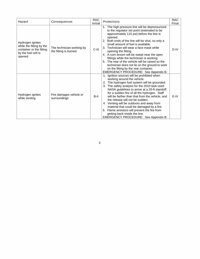
The hazards unique to this work are assessed in the following table. Small, sustained fires are a possibility when hydrogen is released through one vent stack or the other, but the vent stacks open above the height of the vehicle so no damage is anticipated. Brief fires are possible at the instances where a hydrogen-filled line inevitably is opened. The technician working in the vicinity of a possible hydrogen fire will wear a face mask. Asphyxiation is unlikely because the work is outdoors. A catastrophic pressure release is not expected because this is a de-pressurizing procedure. Hypothermia is unlikely because we need not work in bitter cold or rain. These hazards are included for completeness. This work will be completed at West Jeff, so the Risk Assessment Code (RAC) is by ESST’s definitions. See the chart following the table.
Hazard Consequences RAC Initial
Protections RAC Final
Hydrogen remains in the containers after the procedure
Fire during subsequent disassembly
D-II
1. The three containers will be opened individually on every cycle to ensure that all are diluted with nitrogen.
2. The hydrogen detector will be checked when the high-pressure line is opened at the end of the procedure.
3. The containers will be checked again with the hydrogen detector when their end caps are removed at BCS3. If the amount of hydrogen present is more than would come from diffusion, the container will be flushed again with a CO2 extinguisher.
E-II
3
Hazard Consequences RAC Initial
Protections RAC Final
Hydrogen ignites while the fitting by the container or the fitting by the fuel cell is opened
The technician working by the fitting is burned
C-III
1. The high-pressure line will be depressurized to the regulator set point (estimated to be approximately 115 psi) before the line is opened.
2. Both ends of the line will be shut, so only a small amount of fuel is available.
3. Technician will wear a face mask while opening the fitting.
4. A corn broom will be swept near the open fittings while the technician is working.
5. The rear of the vehicle will be raised so the technician does not lie on the ground to work on the fitting by the rear container.
EMERGENCY PROCEDURE: See Appendix B.
D-IV
Hydrogen ignites while venting
Fire damages vehicle or surroundings
B-II
1. Ignition sources will be prohibited when working around the vehicle.
2. The hydrogen fuel system will be grounded. 3. The safety analysis for the 2010 task used
NASA guidelines to arrive at a 20-ft standoff for a sudden fire of all the hydrogen. Staff will be farther than that from the vehicle, and the release will not be sudden.
4. Venting will be outdoors and away from material that could be damaged by a fire.
5. Flame arrestors will prevent the fire from getting back inside the line.
EMERGENCY PROCEDURE: See Appendix B.
E-IV

4
Hazard Consequences RAC Initial
Protections RAC Final
Asphyxiation due to breathing accumulated gasses used in the procedure
Entering a region where the oxygen content has fallen below 19.5% can cause unconsciousness, coma, and possibly death.
E-III
1. Work will be performed outside to allow released gases to escape freely.
2. Vent stacks will be installed to vent the released gases above head height.
3. Staff will be briefed on the physiological signs of asphyxiation.
EMERGENCY PROCEDURE: See Appendix C.
E-IV
Overpressure
Overpressure waves caused by hydrogen ignition or sudden pressure release can cause eardrum damage, lung rupture, and possibly death.
E-III
1. All potential ignition sources will be removed from the work area.
2. Stainless steel hydrogen lines must be grounded.
3. Personnel must stand at a distance of 50 ft while venting large volumes of hydrogen.
4. Personnel must wear in-ear hearing protection while gases are being vented.
EMERGENCY PROCEDURE: Personnel with suspected hearing loss will be referred to Battelle Health Services.
E-IV
Hypothermia, frostbite
Hypothermia occurs mostly at very cold temperatures, but it can occur even at cool temperatures (above 40°F) if a person becomes chilled from rain or sweat.
C-IV
Personnel will wear winter clothing. (Ordinarily, cotton is required for handling hydrogen. Jackets with a cotton shell have a synthetic lining. Personnel will ground themselves to the vehicle before touching a hydrogen fitting.) EMERGENCY PROCEDURE: See Appendix D.
E-IV

5
Hazard Consequences RAC Initial
Protections RAC Final
Vehicle falls off its jacks
Pinned personnel or crush injury
C-II
1. Vehicles will be on level ground. 2. Sturdy jacks will be on both sides of the
vehicle frame on its normal jacking locations. 3. Front tires will be chocked. 4. Personnel working under the vehicle will use
wrenches to react the force to avoid putting side load on the jacks.
5. Personnel will reach under the vehicle but not lie on the ground under it.
EMERGENCY PROCEDURE: If a staff member is pinned under the vehicle, others will call the Battelle control center at 424-4444. If there is no injury, staff will thoroughly determine the reason for the jacks’ failure before resuming the procedure.
E-III

6

7
Personal Protective Equipment
Personnel executing this procedure will wear safety glasses and safety shoes. Personnel within arm’s reach of hydrogen will wear a face shield. Personnel working with a hydrogen fitting will wear a grounding wrist strap. Ear plugs are required when gases are venting. Warm clothing appropriate to the weather is required.
Equipment and tools
Five nitrogen bottles, K or larger, with regulator and gages, on a sturdy cart One CO2 fire extinguisher for each vehicle One ABC fire extinguisher Video camera and tripod Corn broom 12-V car battery 5-V supply or regulator for the pressure transducers Tape measure, at least 50 ft Sturdy jacks, wheel chocks Clock or stopwatch, calibration not necessary Grounding rod and a means to put it in the ground Insulating tape Special supplies built in Appendix A Non-sparking wrenches 5/32 socket torque wrench, capable of 4 ft-lb
Model ___________________ Calibration due _____________________ Voltmeter
Model ___________________ Calibration due _____________________ Hydrogen detector
Model ___________________ Calibration due _____________________ Hydrogen-compatible pressure transducer
Model ___________________ Calibration due _____________________

8
Legend for the table of instructions
Step Instruction Initials and date
1 Major steps have a single digit in the step number
1.1 Steps that are composed of a number of smaller steps have a dark shading. Steps with a dark shading do not require initials in the final column.
1.1.1 After finishing an individual step, the technician will initial and date the row at the right, to confirm that the step has been completed.
/

9
3
4
1 2
The callout numbers in the square boxes are referenced in the steps of the procedure.
1. The quarter-turn manual valve opens the outlet from the low-pressure line. 2. The low-pressure receptacle is where the first vent stack will be installed. 3. The high-pressure line, after it has been vented to low pressure, will be opened at
an elbow by the rear container. A second vent stack will be installed here. 4. The low-pressure line to the fuel cell will be cleared near the end of the procedure.
Passenger
Driver
Re
ar
Fro
nt
This sketch is looking at the fuel system from the driver side of the vehicle.

10
1
2
3
4
This is a schematic diagram of the fuel system. The callout numbers in the square boxes indicate the same features as those on the previous page.

11
Table of Instructions
Step Instructions initials
1 Depressurize the hydrogen fuel system to the regulator setpoint (about 115 psi)
1.1 Review the safety analysis
1.1.1 Remove all possible ignition sources. Leave cell phones turned on in case of emergency, but put them in a place where they will not be carried close to the vehicle.
/
1.1.2 This procedure must be executed once for each vehicle. Write the description of the current vehicle on the front page.
/
1.1.3
Brief all personnel on the hazard analysis and safety procedures. Put on protective eye wear. NOTE: Eye protection is required at all times. Hearing Protection is required in steps in which gas is being vented. Ensure that the safety equipment is readily available. Brief all personnel on the correct operation of the fire extinguisher. Ensure that a first aid kit is easily accessible.
/
1.1.4
Talk through the steps of the procedure and assign roles. Personnel performing the procedure will sign and write their names here.
/
1.2 Confirm that the preparations in Appendix A have been completed. / 1.3 Position and prepare the vehicle
1.3.1 Park the vehicle outside, in a location away from people, property, and possible ignition sources. No smoking is permitted near the vehicles.
/
1.3.2 Open the vehicle’s doors or windows and leave them open while the hydrogen is venting.
/
1.3.3 Safe the 12V battery in the engine compartment. 1.3.3.1 Disconnect the battery. /
1.3.3.2 Cover the terminals with an electrical insulator to prevent inadvertent contact.
/
1.3.4 Confirm that the lithium battery has been removed from the luggage compartment.
/
1.3.5 Raise the rear of the vehicle to lift both tires off the ground by chocking the front tires and putting the rear on sturdy jacks.
/
1.4 Ground the stainless steel lines coming from the three hydrogen containers to a suitable earth ground. The earth ground should be an 8-ft copper rod with a 3/4” diameter driven at least 6 ft into the ground.
/
1.5 Confirm that the quarter-turn manual valve located downstream of the regulator is closed. (Callout 1 on page 9)
/

12
Step Instructions initials
1.6
Confirm that the manual lockdown valve on each solenoid is closed. The 5/32” hex stem should be torqued clockwise to 4 ft-lb.
1.6.1 Confirm the front container is locked. / 1.6.2 Confirm the middle container is locked. / 1.6.3 Confirm the rear container is locked. / 1.7 Inspect the two vent stacks, if used in prior venting. 1.7.1.1 Inspect the flashback arrestor for any signs of damage. / 1.7.1.2 Inspect the O-rings for any nicks or signs of a potential leak path. / 1.7.1.3 Inspect the flanged sealing face of the tube end. /

13
Step Instructions initials
1.8 Install the first vent stack.
1.8.1
Remove the low-pressure fuel receptacle.
This photograph looks backward toward the driver side rear tire.
This photograph is a closer view.
/
This fitting is the low-pressure fuel receptacle (Callout 2 on page 9). It will be removed to attach the first vent stack.
Low-pressure fuel receptacle
The quarter-turn manual valve
This is the quarter-turn manual valve (Callout 1 on page 9).

14
Step Instructions initials
1.8.2 Attach the first vent stack to the location where the low-pressure fuel receptacle used to be.
/
1.8.3 Secure the first vent stack to the vehicle to prevent it from falling over or whipping as hydrogen is being released.
/
1.9 Prepare for the venting
1.9.1 Clear the surrounding area of any unnecessary personnel. Close down any access roads that are within 60 ft of the venting location.
/
1.9.2 Choose a location for the equipment that is at least 50 ft from the vehicle and generally upwind of the vehicle.
/
1.9.3 Put a videocamera on a tripod aimed at the vehicle and begin recording. / 1.10 Open the valves in order
1.10.1 Open the manual lockdown valves on each of the three hydrogen containers.
1.10.1.1 Approach the vehicle and ground your body to it. /
1.10.1.2 Turn the 5/32" hex stem completely counter clockwise to the full open position.
1.10.1.2. Unlock the front container. / 1.10.1.2.2Unlock the middle container. / 1.10.1.2.3Unlock the rear container. /
1.10.2 Vent the high-pressure hydrogen lines upstream of the regulator. (This step does not depressurize the hydrogen containers.)
1.10.2.1 Approach the vehicle and ground your body to it. /
1.10.2.2 CAUTION: Hydrogen will be released in this step. Open the quarter turn manual valve.
/
1.10.2.3 When hydrogen is flowing, walk away from the vehicle to the 50-ft standoff distance.
/
1.10.2.4
Allow the hydrogen to escape until the venting has apparently ceased. Monitor the readings of the two pressure transducers. The reading of the in the low-pressure transducer should return to approximately zero, and the high-pressure transducer reading should drop to approximately 115 psi. See page 24.
/
1.10.3
CAUTION: Hydrogen will be released in this step. Move the prescribed 50-foot standoff distance away from the vehicle. Energize the three solenoid valves one at a time by connecting the solenoid cable terminal pairs to the battery. This will vent the three individual hydrogen containers.
1.10.3.1 Energize the front solenoid valve. Confirm that the container vented. Leave the solenoid energized.
/
1.10.3.2 Wait until the container appears to have finished venting. /
1.10.3.3 Energize the middle solenoid valve. Confirm that the container vented. Leave the solenoid energized.
/
1.10.3.4 Wait until the container appears to have finished venting. /

15
Step Instructions initials
1.10.3.5 Energize the rear solenoid valve. Confirm that the container vented. Leave the solenoid energized.
/
1.10.3.6 Wait an additional five minutes after the third hydrogen container has apparently ceased venting.
/
1.10.4
If venting was observed upon energizing each of the three hydrogen containers, continue on to the next step. Otherwise consult with safety personnel regarding the appropriate course of action. NOTE: the hydrogen fuel system will still contain hydrogen at approximately 115 psi.
/
1.10.4.1 Check the pressure in the hydrogen containers by reading the voltage on the high pressure transducer. Record the voltage here _________
/
1.10.4.1.Convert the raw voltage to a pressure using the table on page 24. Write the pressure here __________
/
1.10.4.2 Check the pressure in the low pressure vent lines by reading the voltage on the low pressure transducer. Record the voltage here __________
/
1.10.4.2.Convert the raw voltage to a pressure using the table on page 24. Write the pressure here __________
/
1.10.5
If the high pressure transducer is reading between 50 and 150 psi, proceed to the next step. (Recall that the transducers are not calibrated nor necessarily reliable.) Otherwise, confer with safety personnel about continuing to vent the vehicles.
/
1.10.6 De-energize all three solenoid valves by removing the solenoid cable terminals from the battery.
/
1.10.7 Leave the quarter-turn manual valve open to ensure that the low pressure lines do not become repressurized.
/
2 Depressurize the high-pressure tubing (currently at approximately 115 psi) to atmospheric pressure.
2.1 Close the manual lockdown valve on each of the three hydrogen containers.
2.1.1 Approach the vehicle and ground your body to it. Use a corn broom to verify that there is no fire in the vicinity of the hydrogen discharge.
/
2.1.2 Turn the 5/32” hex stem clockwise to a torque of 4 ft-lb. 2.1.2.1 Lock front hydrogen container. / 2.1.2.2 Lock middle hydrogen container. / 2.1.2.3 Lock rear hydrogen container. / 2.2 Prepare and crack open the hydrogen fitting 2.2.1 Put on a face shield. / 2.2.2 Approach the vehicle and ground your body to it. /

16
Step Instructions initials
2.2.3
CAUTION: Hydrogen will be released in this step. Using non-sparking tools, slowly crack open one of the fittings on the elbow by the rear container.
/
2.2.4 After confirming that hydrogen is escaping from the fitting, retreat to the safe zone.
/
2.2.5 From the 50-ft standoff distance, allow the hydrogen to escape from the fitting until the venting has apparently ceased, a minimum of five minutes.
/
2.2.6 Use a CO2 fire extinguisher to flush out any hydrogen that may have been trapped underneath or inside the vehicle. Use a corn broom to verify that there is no fire in the vicinity of the hydrogen discharge.
/
2.2.7 Use the hydrogen detector to check for pockets of hydrogen under the vehicle or inside the passenger compartment. If necessary, flush with the fire extinguisher again.
/
3 Depressurize the hydrogen system to atmospheric pressure 3.1 Install the second vent stack.
3.1.1
Approach the vehicle and ground your body to it. CAUTION: Hydrogen at atmospheric pressure will be present in the line. If one of the containers has a valve with a faulty seal, a continuing flow of hydrogen may be present. While one technician works with the line, another will hold the corn broom nearby to check for a fire. Difficulty with simple dexterity tasks may be a sign of oxygen deprivation or cold fingers.
/
This elbow beneath the valve on the rear container is Callout 3 on page 9. Cautiously crack a fitting here to begin releasing hydrogen from the high-pressure line.

17
Step Instructions initials
3.1.2 Finish loosening the elbow, remove it, and replace it with a tee. /
3.1.3
Connect the second vent stack to the tee and tighten it.
This schematic of the second vent stack and its components is not to scale.
/
3.1.4 Secure the vent stack to the vehicle. /
3.1.5 Attach the nitrogen bottle to the fitting on the second vent stack. Ground the bottle to the vent stack.
/
3.1.6 Close the valve leading to the connection for the nitrogen bottle. / 3.1.7 Open the valve leading to the outlet through the arrestor. /
3.2 Unlock the manual shutoff valves on each of the three hydrogen containers
3.2.1 Turn the 5/32” hex stem completely counter clockwise to the full open position.
3.2.1.1 Unlock the front hydrogen container. / 3.2.1.2 Unlock the middle hydrogen container. / 3.2.1.3 Unlock the rear hydrogen container. /
3.3
CAUTION: Hydrogen will be released in this step. Move the prescribed 50-ft standoff distance away from the vehicle. Energize the three solenoid valves by connecting all three solenoid cable terminal pairs to the battery. This will vent the hydrogen fuel system.
To the middle and front containers
This tubing is the second vent stack.
Arrestor
The nitrogen bottle and regulator will be installed at this valve.
Calibrated pressure transducer
Excess flow valve from the rear container
This tee replaces the elbow in the photo in Step 2.2.3.
18
Step Instructions initials
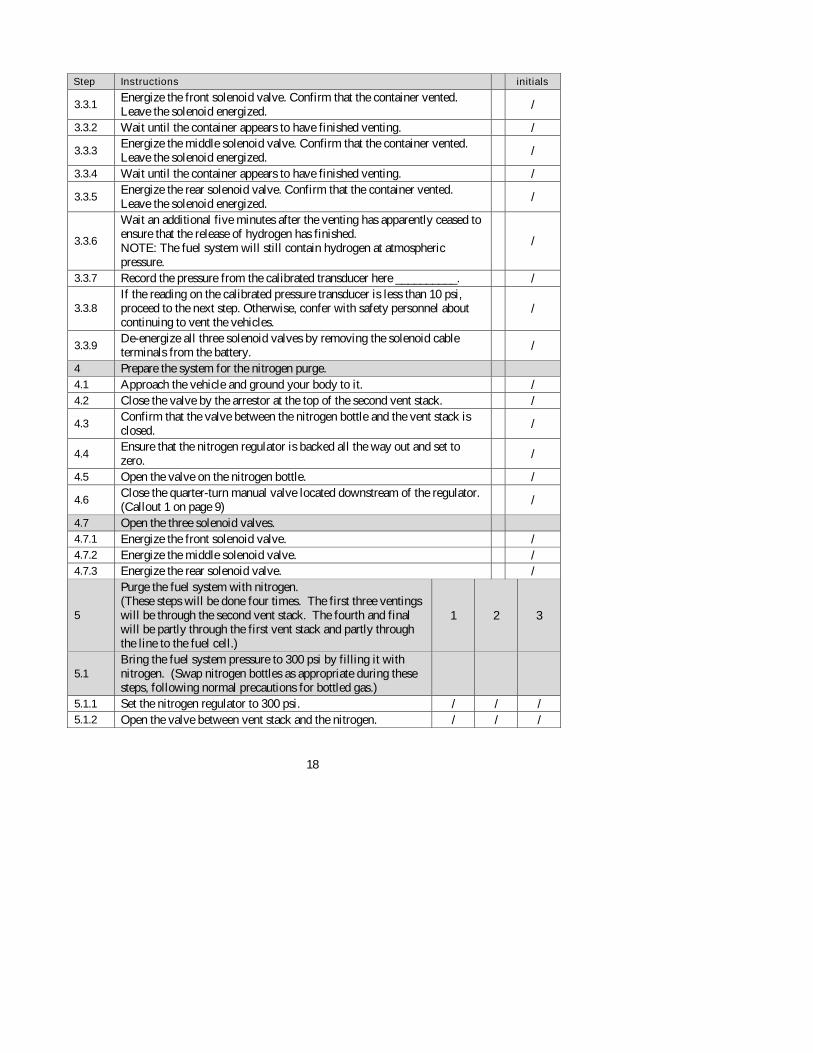
3.3.1 Energize the front solenoid valve. Confirm that the container vented. Leave the solenoid energized.
/
3.3.2 Wait until the container appears to have finished venting. /
3.3.3 Energize the middle solenoid valve. Confirm that the container vented. Leave the solenoid energized.
/
3.3.4 Wait until the container appears to have finished venting. /
3.3.5 Energize the rear solenoid valve. Confirm that the container vented. Leave the solenoid energized.
/
3.3.6
Wait an additional five minutes after the venting has apparently ceased to ensure that the release of hydrogen has finished. NOTE: The fuel system will still contain hydrogen at atmospheric pressure.
/
3.3.7 Record the pressure from the calibrated transducer here __________. /
3.3.8 If the reading on the calibrated pressure transducer is less than 10 psi, proceed to the next step. Otherwise, confer with safety personnel about continuing to vent the vehicles.
/
3.3.9 De-energize all three solenoid valves by removing the solenoid cable terminals from the battery.
/
4 Prepare the system for the nitrogen purge. 4.1 Approach the vehicle and ground your body to it. / 4.2 Close the valve by the arrestor at the top of the second vent stack. /
4.3 Confirm that the valve between the nitrogen bottle and the vent stack is closed.
/
4.4 Ensure that the nitrogen regulator is backed all the way out and set to zero.
/
4.5 Open the valve on the nitrogen bottle. /
4.6 Close the quarter-turn manual valve located downstream of the regulator. (Callout 1 on page 9)
/
4.7 Open the three solenoid valves. 4.7.1 Energize the front solenoid valve. / 4.7.2 Energize the middle solenoid valve. / 4.7.3 Energize the rear solenoid valve. /
5
Purge the fuel system with nitrogen. (These steps will be done four times. The first three ventings will be through the second vent stack. The fourth and final will be partly through the first vent stack and partly through the line to the fuel cell.)
1 2 3
5.1 Bring the fuel system pressure to 300 psi by filling it with nitrogen. (Swap nitrogen bottles as appropriate during these steps, following normal precautions for bottled gas.)
5.1.1 Set the nitrogen regulator to 300 psi. / / / 5.1.2 Open the valve between vent stack and the nitrogen. / / /
19
Step Instructions initials
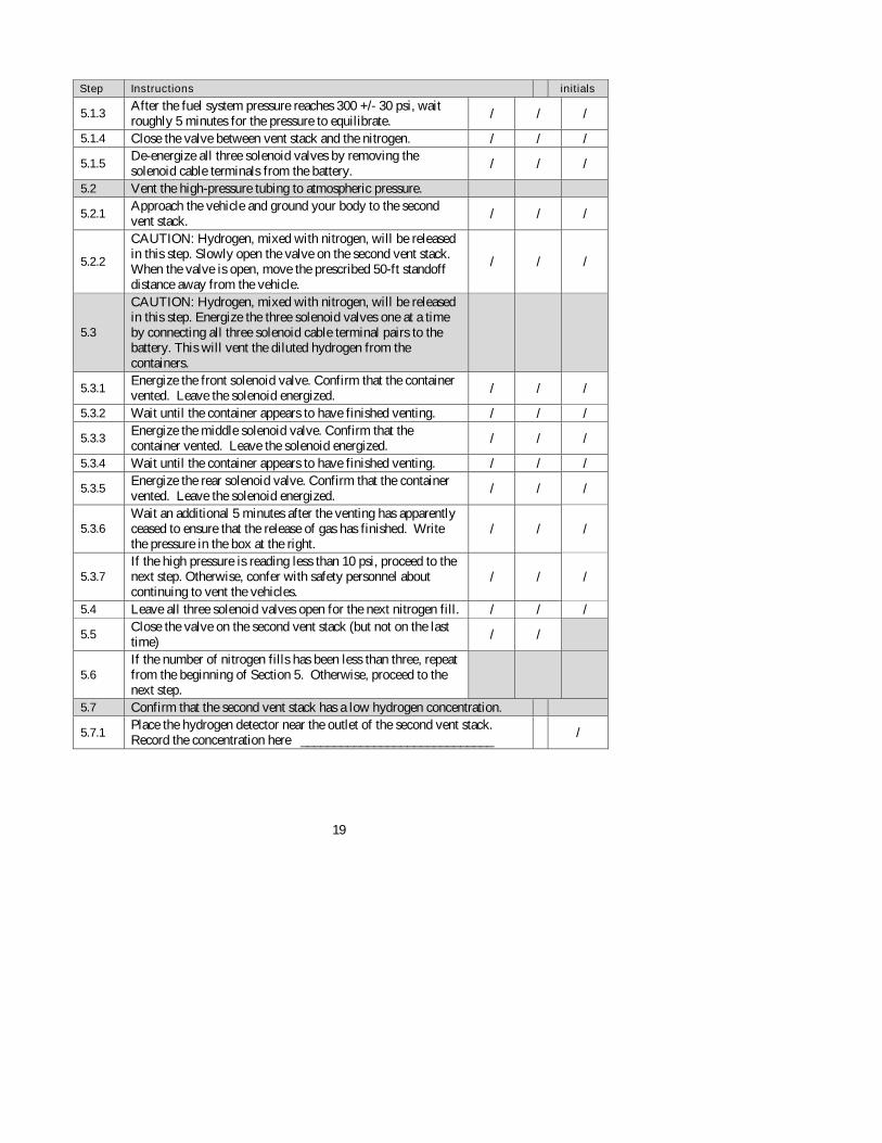
5.1.3 After the fuel system pressure reaches 300 +/- 30 psi, wait roughly 5 minutes for the pressure to equilibrate.
/ / /
5.1.4 Close the valve between vent stack and the nitrogen. / / /
5.1.5 De-energize all three solenoid valves by removing the solenoid cable terminals from the battery. / / /
5.2 Vent the high-pressure tubing to atmospheric pressure.
5.2.1 Approach the vehicle and ground your body to the second vent stack. / / /
5.2.2
CAUTION: Hydrogen, mixed with nitrogen, will be released in this step. Slowly open the valve on the second vent stack. When the valve is open, move the prescribed 50-ft standoff distance away from the vehicle.
/ / /
5.3
CAUTION: Hydrogen, mixed with nitrogen, will be released in this step. Energize the three solenoid valves one at a time by connecting all three solenoid cable terminal pairs to the battery. This will vent the diluted hydrogen from the containers.
5.3.1 Energize the front solenoid valve. Confirm that the container vented. Leave the solenoid energized. / / /
5.3.2 Wait until the container appears to have finished venting. / / /
5.3.3 Energize the middle solenoid valve. Confirm that the container vented. Leave the solenoid energized. / / /
5.3.4 Wait until the container appears to have finished venting. / / /
5.3.5 Energize the rear solenoid valve. Confirm that the container vented. Leave the solenoid energized.
/ / /
5.3.6 Wait an additional 5 minutes after the venting has apparently ceased to ensure that the release of gas has finished. Write the pressure in the box at the right.
/ / /
5.3.7 If the high pressure is reading less than 10 psi, proceed to the next step. Otherwise, confer with safety personnel about continuing to vent the vehicles.
/ / /
5.4 Leave all three solenoid valves open for the next nitrogen fill. / / /
5.5 Close the valve on the second vent stack (but not on the last time)
/ /
5.6 If the number of nitrogen fills has been less than three, repeat from the beginning of Section 5. Otherwise, proceed to the next step.
5.7 Confirm that the second vent stack has a low hydrogen concentration.
5.7.1 Place the hydrogen detector near the outlet of the second vent stack. Record the concentration here _____________________________
/

20
Step Instructions initials
5.7.2
If the concentration from the previous step is below 1% (10,000 ppm), continue to the next step. Otherwise confer with safety personnel about performing additional purge cycles until the concentration of H2 is below 1%.
/
5.8 Clear the residual hydrogen in the first vent stack and the line to the fuel cell.
5.8.1 Bring the fuel system pressure to 300 psi by filling it with nitrogen. 5.8.1.1 Close the valve on the second vent stack. / 5.8.1.2 Set the nitrogen regulator to 300 psi / 5.8.1.3 Open the valve between vent stack and the nitrogen. /
5.8.1.4 After the fuel system pressure reaches 300 +/- 30 psi, wait roughly 5 minutes for the pressure to equilibrate.
/
5.8.1.5 Close the valve between vent stack and the nitrogen. /
5.8.2 De-energize all three solenoid valves by removing the solenoid cable terminals from the battery. /
5.8.3 Exhaust diluted hydrogen (from the front container) through the regulator. 5.8.3.1 Approach the vehicle and ground your body to it.
5.8.3.2 CAUTION: Hydrogen at approximately 115 psi will be released in this step. Open the quarter-turn manual valve.
/
5.8.3.3 Move the prescribed 50-foot standoff distance away from the vehicle. /
5.8.3.4 CAUTION: Hydrogen, mixed with nitrogen, will be released in this step. Energize the front solenoid valve. Confirm that the container vented. Leave the solenoid energized.
/
5.8.3.5 Wait until the container appears to have finished venting, at least five minutes. /
5.8.3.6 Confirm that the low-pressure line and first vent stack have a low hydrogen concentration.
5.8.3.6.1 Place the hydrogen detector near the outlet of the first vent stack. Record the concentration here __________
/
5.8.3.6.2
If the concentration from the previous step is below 1% (10,000 ppm), continue to the next step. Otherwise confer with safety personnel about performing additional purge cycles until the concentration of H2 is below 1%.
/
5.9 Clear hydrogen from the line to the fuel cell. 5.9.1 Put on a face mask. / 5.9.2 Approach the vehicle and ground your body to it. / 5.9.3 Close the quarter-turn manual valve. /
5.9.4
CAUTION: Hydrogen at approximately 115 psi will be released in this step. Open the hood, locate the end of the line carrying hydrogen to the fuel cell, and disconnect it using non-sparking tools. (Callout 4 on page 9)
/

21
Step Instructions initials
5.9.5 Move the prescribed 50-foot standoff distance away from the vehicle. /
5.9.6 CAUTION: Hydrogen, mixed with nitrogen, will be released in this step. Energize the middle solenoid valve. Confirm that the container vented.
/
5.9.7 CAUTION: Hydrogen, mixed with nitrogen, will be released in this step. Energize the rear solenoid valve. Confirm that the container vented. Leave the solenoid energized.
/
5.9.8 Wait until the container appears to have finished venting, at least five minutes. /
5.9.9 Confirm that the line to the fuel cell has a low hydrogen concentration.
5.9.9.1 Place the hydrogen detector under the hood near the outlet of the hydrogen line. Record the concentration here __________
/
5.9.9.2
If the concentration from the previous step is below 1% (10,000 ppm), continue to the next step. Otherwise confer with safety personnel about performing additional purge cycles until the concentration of H2 is below 1%.
/
5.10 Open the valve on the second vent stack to vent the system from 115 psi to atmospheric.
/
6 Finish the process 6.1.1 Confirm that the fuel system is in the desired zero-energy state.
6.1.2 De-energize all three solenoid valves by removing the solenoid cable terminals from the battery.
/
6.1.3
CAUTION: This step will release a small amount of hydrogen that is upstream of the check valve. Crack a fitting by the check valve on the vehicle’s fuel inlet port using non-sparking tools.
/
6.2 Check the vicinity of the vehicle again with the hydrogen detector. / 6.3 It is safe to disassemble the fuel system.
6.4
Hydrogen has probably diffused from the interior of the containers to the space between the metal liner and the polymer shell. Some of this hydrogen will come back to the interior of the container before the end caps are removed days later, but the concentration is unlikely to be of concern. It’s a good idea to open the containers cautiously and check the hydrogen concentration, just to be on the safe side.

22
Appendix A Prepar ing Support Equipment
These steps are to be done in town before the procedure proper begins. The major steps in the separate tables can be performed in any order. Step Instruction
1 Prepare the Solenoid Valves 1.1 Lock the manual shut off valve on each of the three containers
1.1.1 Turn the 5/32" hex stem clockwise to a torque of 4 ft-lb. (The stem is located on the face of each valve; see Figure 3.)
1.1.1.1 Lock front container. 1.1.1.2 Lock middle container. 1.1.1.3 Lock rear container.
1.2 Detach the connectors attached to the wire bundle coming out of each of the three solenoid valves.
1.3
Note the colors of the wires going into the connector attached to the solenoid valve. (the wire colors in each bundle should be consistent between solenoids. If they are NOT, please note accordingly) _______________________________________________________________________________________________________________
1.4 If two of the wire colors are white, the solenoid excitation is 12V. If two of the wire colors are orange the solenoid excitation is 24V. Record the solenoid excitation voltage here __________________
1.5 Create three cables with the mating connectors.
1.5.1 Note the pin positions of the solenoid excitation wires (white or orange). Write them here
1.5.2 Assemble the three mating connectors for the solenoid valves. The connector must be Packard/Delphi (PN 12103639, Mate PN 12052848).
1.5.2.1 The three cables should be at least 60 ft in length
1.5.2.2 Attach terminals suitable for securing to a 12-V car battery. DO NOT CONNECT THE TERMINALS TO THE BATTERY YET.
1.5.2.3 Label each of the three cables to distinguish them as front, middle and rear solenoid valves.
1.6 Mate each of the three cables to each of the three solenoid connectors. 1.7 Confirm that all three solenoid valves can be opened.
1.7.1 Open and close the front solenoid valve by momentarily connecting the terminals to a 12-V battery. Confirm its action by the clicking sound.
1.7.2 Open and close the middle solenoid valve by momentarily connecting the terminals to a 12-V battery. Confirm its action by the clicking sound.
23
Step Instruction
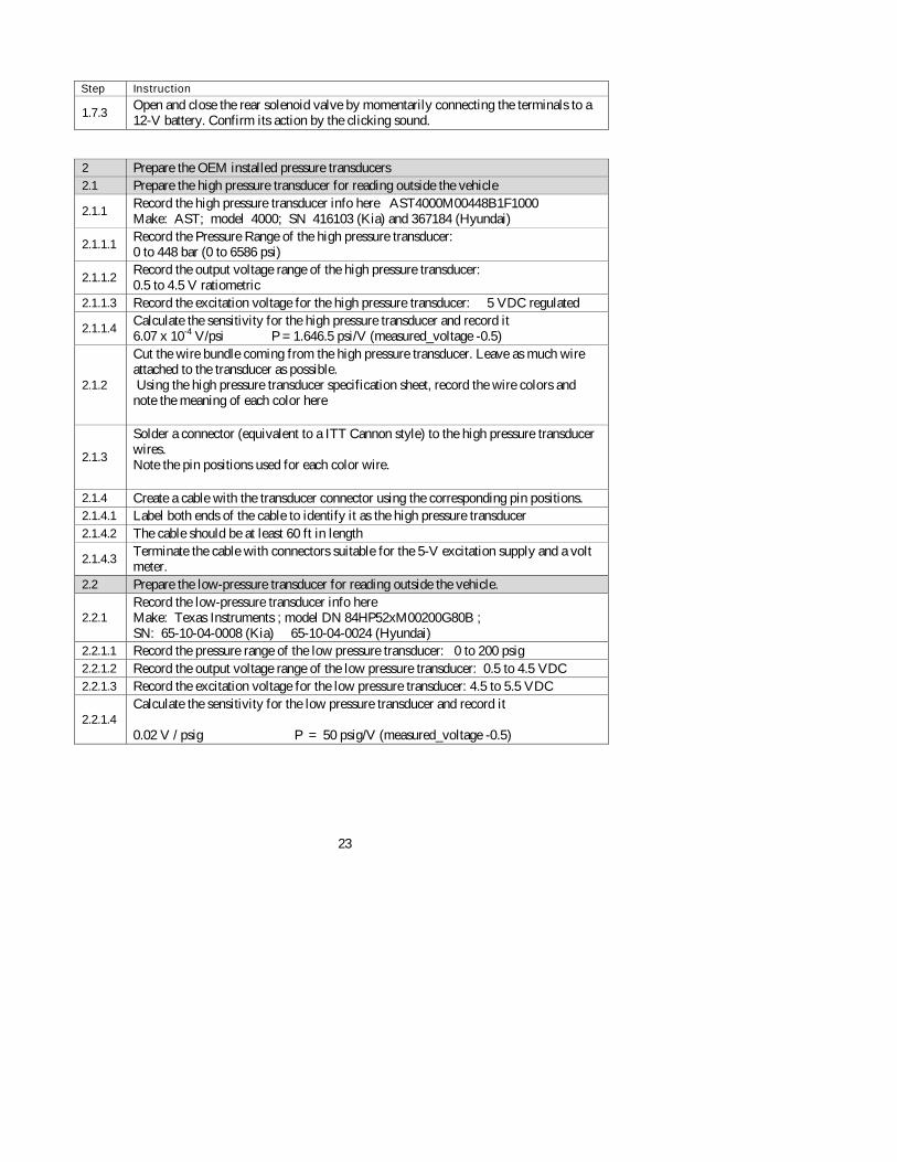
1.7.3 Open and close the rear solenoid valve by momentarily connecting the terminals to a 12-V battery. Confirm its action by the clicking sound.
2 Prepare the OEM installed pressure transducers 2.1 Prepare the high pressure transducer for reading outside the vehicle
2.1.1 Record the high pressure transducer info here AST4000M00448B1F1000 Make: AST; model 4000; SN 416103 (Kia) and 367184 (Hyundai)
2.1.1.1 Record the Pressure Range of the high pressure transducer: 0 to 448 bar (0 to 6586 psi)
2.1.1.2 Record the output voltage range of the high pressure transducer: 0.5 to 4.5 V ratiometric
2.1.1.3 Record the excitation voltage for the high pressure transducer: 5 VDC regulated
2.1.1.4 Calculate the sensitivity for the high pressure transducer and record it 6.07 x 10⁻⁴ V/psi P = 1.646.5 psi/V (measured_voltage -0.5)
2.1.2
Cut the wire bundle coming from the high pressure transducer. Leave as much wire attached to the transducer as possible. Using the high pressure transducer specification sheet, record the wire colors and note the meaning of each color here
2.1.3
Solder a connector (equivalent to a ITT Cannon style) to the high pressure transducer wires. Note the pin positions used for each color wire.
2.1.4 Create a cable with the transducer connector using the corresponding pin positions. 2.1.4.1 Label both ends of the cable to identify it as the high pressure transducer 2.1.4.2 The cable should be at least 60 ft in length
2.1.4.3 Terminate the cable with connectors suitable for the 5-V excitation supply and a volt meter.
2.2 Prepare the low-pressure transducer for reading outside the vehicle.
2.2.1 Record the low-pressure transducer info here Make: Texas Instruments ; model DN 84HP52xM00200G80B ; SN: 65-10-04-0008 (Kia) 65-10-04-0024 (Hyundai)
2.2.1.1 Record the pressure range of the low pressure transducer: 0 to 200 psig 2.2.1.2 Record the output voltage range of the low pressure transducer: 0.5 to 4.5 VDC 2.2.1.3 Record the excitation voltage for the low pressure transducer: 4.5 to 5.5 VDC
2.2.1.4 Calculate the sensitivity for the low pressure transducer and record it 0.02 V / psig P = 50 psig/V (measured_voltage -0.5)

24
2.2.2
Cut the wire bundle coming from the low pressure transducer. Using the low pressure transducer specification sheet record the wire colors and note the meaning of each color here
2.2.3
Solder a connector (equivalent to an ITT Cannon style) to the low-pressure transducer wires. Note the pin positions used for each color wire.
2.2.4 Create a cable with the mating low pressure transducer connector using the corresponding pin positions
2.2.4.1 Label the cable to identify it as the low pressure transducer 2.2.4.2 The cable should be at least 60 ft in length
2.2.4.3 Terminate the cable with connectors suitable for the 5-V excitation supply and a volt meter.
2.3 Connect the high pressure transducer to the supplied input voltage and record the voltage reading from the high pressure transducer signal here ______
2.3.1 Convert the raw voltage to a pressure __________________
2.4 Connect the low pressure transducer to the supplied input voltage and record the voltage reading from the low pressure transducer signal here ______
2.4.1 Convert the raw voltage to a pressure __________________
Pressure, psig Reading, V Low Pressure High Pressure
0.5 0 0 1.0 25 823 1.5 50 1,647 2.0 75 2,470 2.5 100 3,293 3.0 125 4,116 3.5 150 4,940 4.0 175 5,763 4.5 200 6,586

25
3 Prepare two vent stacks. NOTE: the vent stacks may be re-used from venting the first vehicle, provided they were not damaged. The material of both vent stacks will be SS 316 or 316L. Both will have a flashback arrestor.
3.1 The first vent stack will attach downstream of the quarter-turn manual valve (Callout 2 on page 9)
3.2 The second vent stack will attach to a new tee in the vehicle’s high-pressure tubing (Callout 3 on page 9). It will have the nitrogen connection and a calibrated pressure transducer (See the schematic at Step 3.1.3). It will have a flashback arrestor.

26
Appendix B EMERGENCY PROCEDURE
in the case of a FIRE
In every instance except two, personnel will be 50 ft from the vehicle while hydrogen is being released. The two occasions when hydrogen is to be released when personnel are near the vehicle is when fitting by the rear container is being opened and when the fitting by the fuel cell is opened. I f a fire grows and begins to consume the vehicle Move away from the area. Do not attempt to fight the fire. Call the Battelle Control Center at 424-4444. The Battelle control center will summon a suppression crew and notify West Jeff Security. I f a fire begins while a line is being cracked Walk 50 ft from the vehicle. Let the fire burn itself out. If nothing is damaged, the procedure can continue. I f the hydrogen coming from a vent stack burns A small hydrogen fire may begin spontaneously as hydrogen is released from a vent stack. Because the hydrogen is released above the top of the vehicle, such a fire is not expected to damage anything. Valves can remain open during a fire from a vent stack that does not threaten the vehicle. I f clothing catches fire Stop, drop, and roll. The ABC fire extinguisher is intended for clothing fires. The CO2 fire extinguisher is intended for flushing hydrogen gas, not for clothing fires. I f someone is burned In the case of a minor burn, the injured staff will be escorted to Battelle Health Services. In the case of more serious burns, personnel will call the Battelle Control Center at 424-4444 for advice on whether to transport the patient to a hospital or to summon emergency medical assistance.

27
Appendix C EMERGENCY PROCEDURE
in the case of ASPHYXIATION
Effects of Oxygen Deficiency on the Human Body Atmospher ic
Oxygen Concentration (%)
Possible Results
20.9 Normal 19.0 Some unnoticeable adverse physiological effects
16.0 Increased pulse and breathing rate, impaired thinking and attention, reduced coordination
14.0
Abnormal fatigue upon exertion, emotional upset, faulty coordination, poor judgment
12.5
Very poor judgment and coordination, impaired respiration that may cause permanent heart damage, nausea, and vomiting
<10 Inability to move, loss of consciousness, convulsions, death
Source: http://www.csb.gov/assets/document/SB-Nitrogen-6-11-03.pdf
If any personnel begin to show signs of impaired judgment or difficulty concentrating, then the affected personnel will be moved well away from the vehicle and venting will be suspended. Other staff will call the Battelle Control Center at 424-4444 to request emergency medical assistance.

28
Appendix D EMERGENCY PROCEDURE
in the case of HYPOTHERMIA
Staff will dress for the weather. This appendix on signs and treatment is taken mostly from a government Web site. When exposed to cold temperatures, your body begins to lose heat faster than it can be produced. Prolonged exposure to cold will eventually use up your body’s stored energy. The result is hypothermia, or abnormally low body temperature. Body temperature that is too low affects the brain, making the victim unable to think clearly or move well. This makes hypothermia particularly dangerous because a person may not know it is happening and won’ t be able to do anything about it. Signs are
• shivering, exhaustion, • confusion, fumbling hands, • memory loss, slurred speech, and • Drowsiness.
What to do: The procedure will be suspended and the affected person will be taken indoors. If the person’s temperature is below 95 °F, the situation is an emergency and staff will call the Battelle Control Center at [redacted] to summon emergency medical assistance. Before medical care arrives, begin warming the person, as follows: Get the victim into a warm room or shelter. If the victim has on any wet clothing, remove it. Warm the center of the body first—chest, neck, head, and groin—using an electric blanket, if available. Or use skin-to-skin contact under loose, dry layers of blankets, clothing, towels, or sheets. Warm beverages can help increase the body temperature, but do not give alcoholic beverages. Do not try to give beverages to an unconscious person. After body temperature has increased, keep the person dry and wrapped in a warm blanket, including the head and neck. Source: Winter Weather; Hypothermia, Centers For Disease Control and Prevention. www.bt.cdc.gov/disasters/winter/staysafe/hypothermia.asp Winter Weather; Frostbite, Centers For Disease Control and Prevention. http://emergency.cdc.gov/disasters/winter/staysafe/frostbite.asp

10846A1-020415-v2