process mining using bpmn: relating event logs and process ...wvdaalst/publications/p901.pdf ·...
TRANSCRIPT

Process mining using BPMN: relating event logs andprocess modelsKalenkova, A.A.; van der Aalst, W.M.P.; Lomazova, I.A.; Rubin, V.A.
Published in:Software and Systems Modeling
DOI:10.1007/s10270-015-0502-0
Published: 01/10/2017
Document VersionAccepted manuscript including changes made at the peer-review stage
Please check the document version of this publication:
• A submitted manuscript is the author's version of the article upon submission and before peer-review. There can be important differencesbetween the submitted version and the official published version of record. People interested in the research are advised to contact theauthor for the final version of the publication, or visit the DOI to the publisher's website.• The final author version and the galley proof are versions of the publication after peer review.• The final published version features the final layout of the paper including the volume, issue and page numbers.
Link to publication
Citation for published version (APA):Kalenkova, A. A., van der Aalst, W. M. P., Lomazova, I. A., & Rubin, V. A. (2017). Process mining using BPMN:relating event logs and process models. Software and Systems Modeling, 16(4), 1019-1048. DOI:10.1007/s10270-015-0502-0
General rightsCopyright and moral rights for the publications made accessible in the public portal are retained by the authors and/or other copyright ownersand it is a condition of accessing publications that users recognise and abide by the legal requirements associated with these rights.
• Users may download and print one copy of any publication from the public portal for the purpose of private study or research. • You may not further distribute the material or use it for any profit-making activity or commercial gain • You may freely distribute the URL identifying the publication in the public portal ?
Take down policyIf you believe that this document breaches copyright please contact us providing details, and we will remove access to the work immediatelyand investigate your claim.
Download date: 14. Jan. 2018

Softw Syst ModelDOI 10.1007/s10270-015-0502-0
REGULAR PAPER
Process mining using BPMN: relating event logs and processmodels
Anna A. Kalenkova1 · Wil M. P. van der Aalst1,2 · Irina A. Lomazova1 ·Vladimir A. Rubin1
Received: 11 March 2015 / Revised: 17 July 2015 / Accepted: 22 September 2015© Springer-Verlag Berlin Heidelberg 2015
Abstract Process-aware information systems (PAIS) aresystems relying on processes, which involve human and soft-ware resources to achieve concrete goals. There is a need todevelop approaches formodeling, analysis, improvement andmonitoring processeswithin PAIS. These approaches includeprocess mining techniques used to discover process modelsfrom event logs, find log and model deviations, and analyzeperformance characteristics of processes. The representa-tional bias (a way to model processes) plays an importantrole in process mining. The BPMN 2.0 (Business ProcessModel and Notation) standard is widely used and allows tobuild conventional and understandable process models. Inaddition to the flat control flow perspective, subprocesses,data flows, resources can be integrated within one BPMNdiagram. This makes BPMN very attractive for both processminers and business users, since the control flow perspec-
Communicated by Prof. Ulrich Frank.
This work is supported by the Scientific Fund of the NationalResearch University Higher School of Economics and is supported byRussian Fund for Basic Research (Project 15-37-21103).
B Anna A. [email protected]
Wil M. P. van der [email protected]
Irina A. [email protected]
Vladimir A. [email protected]
1 National Research University Higher School of Economics,Moscow, Russia
2 Department of Mathematics and Computer Science,Eindhoven University of Technology, Eindhoven, TheNetherlands
tive can be integrated with data and resource perspectivesdiscovered from event logs. In this paper, we describe andjustify robust control flow conversion algorithms, which pro-vide the basis for more advanced BPMN-based discoveryand conformance checking algorithms. Thus, on the basis ofthese conversion algorithms low-level models (such as Petrinets, causal nets and process trees) discovered from eventlogs using existing approaches can be represented in terms ofBPMN.Moreover, we establish behavioral relations betweenPetri nets and BPMN models and use them to adopt existingconformance checking and performance analysis techniquesin order to visualize conformance and performance infor-mation within a BPMN diagram. We believe that the resultspresented in this paper can be used for a wide variety ofBPMN mining and conformance checking algorithms. Wealso provide metrics for the processes discovered before andafter the conversion to BPMN structures. Cases for whichconversion algorithms produce more compact or more com-plicated BPMNmodels in comparisonwith the initial modelsare identified.
Keywords Process mining · Process discovery · Confor-mance checking · BPMN (Business Process Model andNotation) · Petri nets · Bisimulation
1 Introduction
Process-aware information systems (PAIS) are the systemsdesigned to manage processes, operating in various domainsof human activity. There is a natural requirement to monitortheir work and analyze executed processes. In many cases,analysts are interested in a real system behavior, which maybe hidden from domain experts and system engineers. This
123

A. A. Kalenkova et al.
Table 1 An event log of a booking process
Case ID Event name Timestamp Price Client IP
1 Book flight 2014-12-24 08:30:00:232 145 188.44.42.45
1 Get insurance 2014-12-24 08:31:05:171 23 188.44.42.45
2 Book flight 2014-12-24 08:31:08:543 94 93.180.0.62
1 Book hotel 2014-12-24 08:32:08:703 295 188.44.42.45
3 Book flight 2014-12-24 08:32:11:534 192 188.44.50.103
1 Pay 2014-12-24 08:34:17:456 463 188.44.42.45
1 Confirm 2014-12-24 08:35:17:537 463 188.44.42.45
... ... ... ... ...
real behavior can be reconstructed from the event logs. Forthat purpose, Data Science approaches can be applied. Theinterest in Data Science and Big Data signifies the growingimportance of evidence-based approaches. Process miningtechniques provide wide range of data-driven approachesthat are process-centric at the same time. Other data-drivenapproaches are often no process-centric.
Process mining offers techniques for automatic discoveryof process models from event logs, checking compatibilityof process models and event logs (conformance checking)and enhancing discovered processes with additional data [1].Process mining has been successfully applied in a variety ofapplication domains such as healthcare [2], tourism [3] andeducation [4]. There is a IEEE process mining community,including more than 60 organizations [5]. Moreover, thereis a wide range of research and commercial tools availablein this area: ProM, Disco (Fluxicon), ARIS Process Perfor-mance Manager (Software AG), Perceptive Process Mining(Perceptive Software), ProcessAnalyzer (QPR) and Celonis.
Today, BPMN 2.0 (Business Process Model and Nota-tion) [6] is the de facto standard notation for modelingbusiness processes understandable by a wide audience ofpeople. Business analysts and product managers, technicaldesigners and developers, system and enterprise architectseffectively use this notation in their everyday job almosteverywhere where BPM is applied. An absolute majority offreeware and commercial BPM tools and Business Suites,like Oracle BPM Suite, IBM Business Process Manager,jBPM, Activiti, Appian BPM Suite, Bizagi BPM Suite,MagicDraw Enterprise Architect (Sparx), Mega Process(MEGA), Signavio Process Editor and others, either nativelysupport BPMN or provide conversion in order to stay com-patible and up to date. BPMN applicability and best BPMNmodeling practices are presented in [7–9].
The representational bias used for process mining is notonly relevant for the understandability of the results, it isalso vital to guide process discovery by setting a suitableclass of target models. Using the BPMN notation as a rep-resentational bias within process mining opens excellent
perspectives for applicability of process mining: Discoveredprocess models become available and understandable bythe majority of users, the models can be imported/exportedfrom/to any BPMN-aware modeling tool and executed,process mining techniques can be easily integrated to theexisting suites (BPMN serves as an interface in this case).Moreover, BPMN models allow for the combination of dif-ferent perspectives varying from control flow (includingsubprocesses) to the perspective of resources.
In this paper, we present methods for discovering thecontrol flow perspective of a process in terms of BPMN. Itshould be noted that process mining offers plenty of algo-rithms for the control flow discovery and each of them hasits own characteristics. The goal is not to invent new algo-rithms, but to benefit from the existing ones and to make themBPMN-compatible. Thus the discovery of the control flowrelies on conversion algorithms and existing process miningtechniques. To that end we firstly formalize the semanticsfor a subset of BPMN models and then present the con-version algorithms from well-known control flow modelingformalisms such as Petri nets (including non-free-choicePetri nets), causal nets [10] and process trees [11] to BPMN.The conversion algorithms presented in the paper are alsogiven the justifications in order to show that behavioral prop-erties of process models discovered from an event log arepreserved. Moreover, we show relations between languagesof Petri nets and corresponding BPMN models, tacking intoaccount properties of the initial Petri nets.
As a short introductory example, let us consider an eventlog1 reflecting a small portion of the history of a ticket book-ing process, which is presented in Table 1. In this process,people use a Web site to book a flight, a hotel, get insuranceand pay for the ticket. Different people in different casesexecute these activities in a different order. Beside case iden-tifiers, event names and timestamps, an event log can contain
1 In order to give an intuitive example, we consider a simple and expres-sive synthetic event log. The analysis of processmodels discovered fromreal-life event logs is demonstrated in Sect. 9.
123
Process mining using BPMN: relating event logs and process models
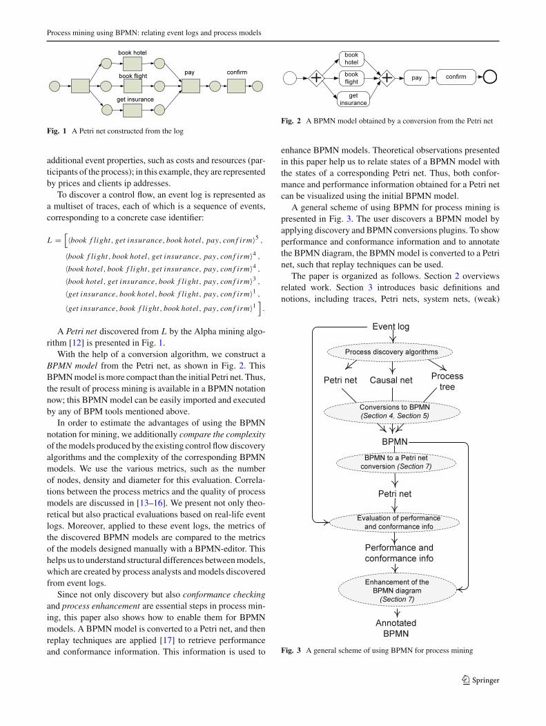
Fig. 1 A Petri net constructed from the log
additional event properties, such as costs and resources (par-ticipants of the process); in this example, they are representedby prices and clients ip addresses.
To discover a control flow, an event log is represented asa multiset of traces, each of which is a sequence of events,corresponding to a concrete case identifier:
L =[〈book f light, get insurance, book hotel, pay, con f irm〉5 ,
〈book f light, book hotel, get insurance, pay, con f irm〉4 ,
〈book hotel, book f light, get insurance, pay, con f irm〉4 ,
〈book hotel, get insurance, book f light, pay, con f irm〉3 ,
〈get insurance, book hotel, book f light, pay, con f irm〉1 ,
〈get insurance, book f light, book hotel, pay, con f irm〉1].
A Petri net discovered from L by the Alpha mining algo-rithm [12] is presented in Fig. 1.
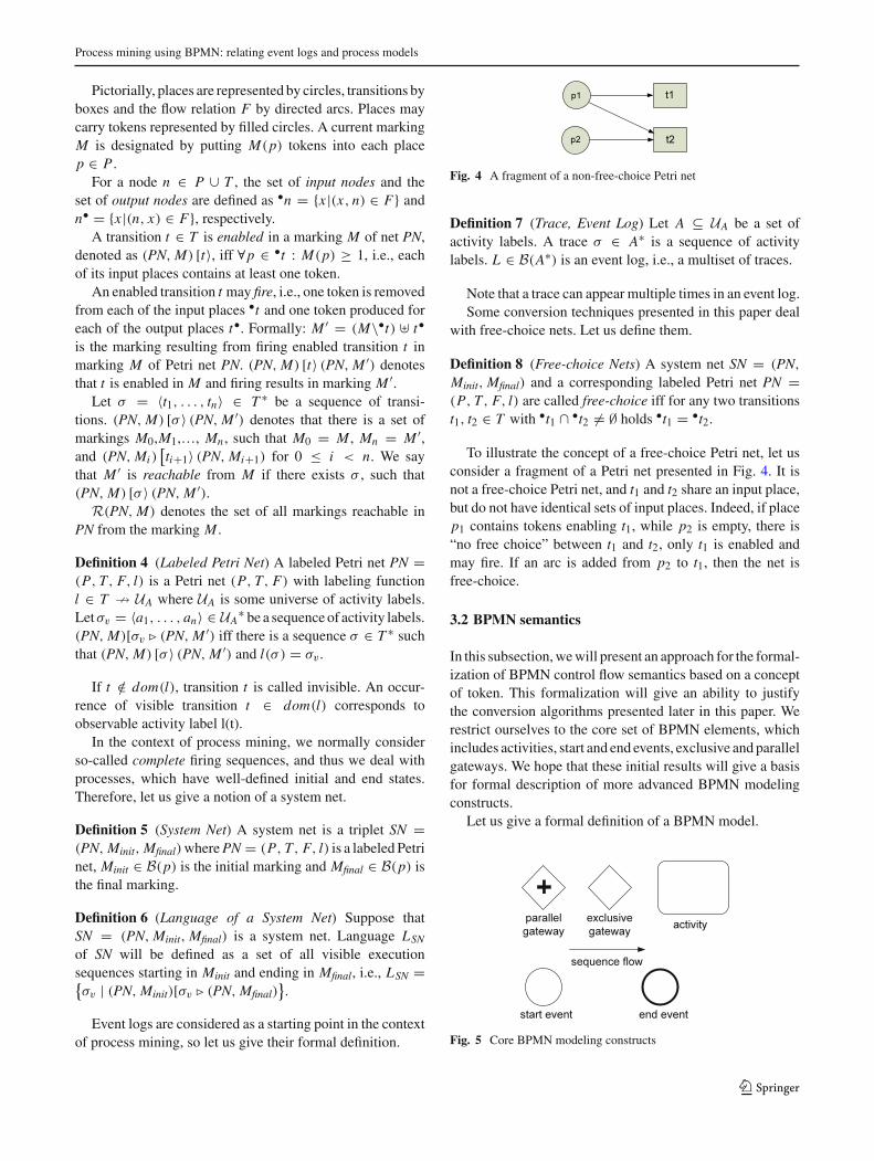
With the help of a conversion algorithm, we construct aBPMN model from the Petri net, as shown in Fig. 2. ThisBPMNmodel ismore compact than the initial Petri net. Thus,the result of process mining is available in a BPMN notationnow; this BPMNmodel can be easily imported and executedby any of BPM tools mentioned above.
In order to estimate the advantages of using the BPMNnotation for mining, we additionally compare the complexityof themodels produced by the existing control flowdiscoveryalgorithms and the complexity of the corresponding BPMNmodels. We use the various metrics, such as the numberof nodes, density and diameter for this evaluation. Correla-tions between the process metrics and the quality of processmodels are discussed in [13–16]. We present not only theo-retical but also practical evaluations based on real-life eventlogs. Moreover, applied to these event logs, the metrics ofthe discovered BPMN models are compared to the metricsof the models designed manually with a BPMN-editor. Thishelps us to understand structural differences betweenmodels,which are created by process analysts andmodels discoveredfrom event logs.
Since not only discovery but also conformance checkingand process enhancement are essential steps in process min-ing, this paper also shows how to enable them for BPMNmodels. A BPMNmodel is converted to a Petri net, and thenreplay techniques are applied [17] to retrieve performanceand conformance information. This information is used to
Fig. 2 A BPMN model obtained by a conversion from the Petri net
enhance BPMN models. Theoretical observations presentedin this paper help us to relate states of a BPMN model withthe states of a corresponding Petri net. Thus, both confor-mance and performance information obtained for a Petri netcan be visualized using the initial BPMN model.
A general scheme of using BPMN for process mining ispresented in Fig. 3. The user discovers a BPMN model byapplying discovery and BPMN conversions plugins. To showperformance and conformance information and to annotatethe BPMN diagram, the BPMNmodel is converted to a Petrinet, such that replay techniques can be used.
The paper is organized as follows. Section 2 overviewsrelated work. Section 3 introduces basic definitions andnotions, including traces, Petri nets, system nets, (weak)
Fig. 3 A general scheme of using BPMN for process mining
123

A. A. Kalenkova et al.
simulation and (weak) bisimulation relations. In Sect. 4,we propose algorithms for conversion from well-known for-malisms such as Petri nets to BPMN and prove correctnessof these conversions. In Sect. 5, transformations of causalnets and process trees to BPMN are introduced. Section 6contains a set of BPMN simplification rules. In Sect. 7, atechnique for conformance checking and performance analy-sis on the basis of BPMNmodels is presented. A tool, whichimplements the proposed conversion and enhancement tech-niques, is presented inSect. 8. Section 9 includes a case study,which shows the results of an application of the algorithmspresented in the paper to real-life event logs. Also the struc-tural business-processesmetrics are calculated and presentedin this section. Section 10 concludes the paper.
2 Related work
This section surveys previouswork on Petri net andworkflowgraph conversions and includes an overview of existing dis-covery and conformance checking techniques dealing with“high-level” process models (e.g., BPMN models and mod-els presented not only by the control flow, but also includingdata and resource perspectives as well).
Algorithms for conversion of free-choice workflow nets[18] (a special subset of Petri nets) to workflow graphs (gen-eralization concept for process modeling notations such asBPMN,UMLActivity [19], EPC [20,21], etc)were proposedin [22,23]. In our paper, we will deal with arbitrary Petri netsstructures and arbitrary safe initial markings. Moreover, incontrast to the approaches proposed before [22,23], we provethat the targetmodel will simulate (i.e., will be able tomimic)the behavior of the initial net and vice versa. These simula-tion relations give the possibility to prove important (in thecontext of processmining) propositions on the language rela-tions. Another key result is that having simulation relationsbetween initial and target models allows us to project variousanalysis data (such conformance and performance informa-tion) obtained for one model to another.
An approach for constructing BPMN models containingsubprocesses was presented in [24]. In contrast to our paper,this technique is mainly focused on deriving subprocessesfrom event logs. We present basic robust conversion algo-rithms, which help to construct flat control flow skeletons ofthe target BPMN models from the discovered Petri nets andother low-levelmodels.Wehope that our approach canbe fur-ther used as a basis for discoveringmore advanced constructs.As [24] our approach is generic and can work with multi-ple discovery algorithms (such as [12,25,26]) in the processmining context. The approach presented in [27] demon-strates the possibility ofminingBPMNmodels covering boththe control flow perspective and the resource perspective.Unfortunately, this approach is rather narrow in scope as it
presents very concrete algorithms for mining BPMN controlflow and resource elements. Algorithms for discovering dataand resources from event logs were proposed in [28–30],respectively. To evaluate the quality of BPMN models andmultiperspective processmodels obtained from the real eventlogs, an analysis of process quality metrics proposed in var-ious studies, such as [13–16], can be applied. An approachfor finding deviations between an event log and a multiper-spective process model was presented in [31].
3 Preliminaries
In this section, we introduce basic notions, event logs, Petrinets, system nets and BPMN semantics.
Multisets are used to present states of Petri nets andBPMNmodels, and also they are used to define event logs, in whichone trace can appear multiple times.
B(A) is the set of all multisets over some set A. For somemultiset b ∈ B(A), b(a) denotes the number of times ele-ment a ∈ A appears in b. By b = [a12, a23] we denotethat elements a1, a2 ∈ A appear in b two and three times,respectively.
The sum of two multisets b and b′ over set A is definedas: (b � b′)(a) = b(a) + b′(a) for all a from A. We say thatb ⊇ b′ iff ∀a ∈ A : b(a) ≥ b′(a). For two multisets b and b′over set A, such that b ⊇ b′, the difference function is definedas: (b\b′)(a) = b(a) − b′(a). The size of a multiset b overset A is denoted by |b| and defined as |b| = ∑
a∈A b(a). Setswill be considered as a special case of multisets, where eachelement can appear 0 or 1 times. Thus, operations applicableto multisets can be applied to sets.
Function f : X � Y is a partial function withdomain dom( f ) ⊆ X and range defined as rng( f ) ={ f (x)|x ∈ dom( f )} ⊆ Y . f : X → Y is a total func-tion, i.e., dom( f ) = X . Let f : X � Y be a partialfunction, f can be applied to sequences of X using the recur-sive definition f (〈〉) = 〈〉 and for some σ ∈ X∗ andx ∈ X f (〈x · σ 〉) = 〈 f (x)〉 · f (σ ), if x ∈ dom( f ) andf (〈x · σ 〉) = f (σ ) otherwise.
3.1 Event logs and Petri nets
Definition 1 (Petri Net) A Petri net is a tuple PN =(P, T, F) with P the set of places, T the set of transitions,P ∩ T = ∅, and F ⊆ (P × T ) ∪ (T × P) the flow relation.
Definition 2 (Marking) Let PN = (P, T, F) be a Petri net.A marking M is a multiset of places, i.e., M ∈ B(P).
Definition 3 (Safe Marking) A marking M of a Petri netPN = (P, T, F) is safe iff ∀p ∈ P : M(p) ≤ 1, i.e., eachplace contains not more than 1 token.
123
Process mining using BPMN: relating event logs and process models
Pictorially, places are represented by circles, transitions byboxes and the flow relation F by directed arcs. Places maycarry tokens represented by filled circles. A current markingM is designated by putting M(p) tokens into each placep ∈ P .
For a node n ∈ P ∪ T , the set of input nodes and theset of output nodes are defined as •n = {x |(x, n) ∈ F} andn• = {x |(n, x) ∈ F}, respectively.
A transition t ∈ T is enabled in a marking M of net PN,denoted as (PN, M) [t〉, iff ∀p ∈ •t : M(p) ≥ 1, i.e., eachof its input places contains at least one token.
An enabled transition t may fire, i.e., one token is removedfrom each of the input places •t and one token produced foreach of the output places t•. Formally: M ′ = (M\•t) � t•is the marking resulting from firing enabled transition t inmarking M of Petri net PN. (PN, M) [t〉 (PN, M ′) denotesthat t is enabled in M and firing results in marking M ′.
Let σ = 〈t1, . . . , tn〉 ∈ T ∗ be a sequence of transi-tions. (PN, M) [σ 〉 (PN, M ′) denotes that there is a set ofmarkings M0,M1,…, Mn , such that M0 = M , Mn = M ′,and (PN, Mi )
[ti+1〉 (PN, Mi+1) for 0 ≤ i < n. We say
that M ′ is reachable from M if there exists σ , such that(PN, M) [σ 〉 (PN, M ′).
R(PN, M) denotes the set of all markings reachable inPN from the marking M .
Definition 4 (Labeled Petri Net) A labeled Petri net PN =(P, T, F, l) is a Petri net (P, T, F) with labeling functionl ∈ T � UA where UA is some universe of activity labels.Letσv = 〈a1, . . . , an〉 ∈ UA
∗ be a sequenceof activity labels.(PN, M)[σv � (PN, M ′) iff there is a sequence σ ∈ T ∗ suchthat (PN, M) [σ 〉 (PN, M ′) and l(σ ) = σv .
If t /∈ dom(l), transition t is called invisible. An occur-rence of visible transition t ∈ dom(l) corresponds toobservable activity label l(t).
In the context of process mining, we normally considerso-called complete firing sequences, and thus we deal withprocesses, which have well-defined initial and end states.Therefore, let us give a notion of a system net.
Definition 5 (System Net) A system net is a triplet SN =(PN, Minit, Mfinal)wherePN = (P, T, F, l) is a labeled Petrinet, Minit ∈ B(p) is the initial marking and Mfinal ∈ B(p) isthe final marking.
Definition 6 (Language of a System Net) Suppose thatSN = (PN, Minit, Mfinal) is a system net. Language LSN
of SN will be defined as a set of all visible executionsequences starting in Minit and ending in Mfinal, i.e., LSN ={σv | (PN, Minit)[σv � (PN, Mfinal)
}.
Event logs are considered as a starting point in the contextof process mining, so let us give their formal definition.
Fig. 4 A fragment of a non-free-choice Petri net
Definition 7 (Trace, Event Log) Let A ⊆ UA be a set ofactivity labels. A trace σ ∈ A∗ is a sequence of activitylabels. L ∈ B(A∗) is an event log, i.e., a multiset of traces.
Note that a trace can appear multiple times in an event log.Some conversion techniques presented in this paper deal
with free-choice nets. Let us define them.
Definition 8 (Free-choice Nets) A system net SN = (PN,
Minit, Mfinal) and a corresponding labeled Petri net PN =(P, T, F, l) are called free-choice iff for any two transitionst1, t2 ∈ T with •t1 ∩ •t2 �= ∅ holds •t1 = •t2.
To illustrate the concept of a free-choice Petri net, let usconsider a fragment of a Petri net presented in Fig. 4. It isnot a free-choice Petri net, and t1 and t2 share an input place,but do not have identical sets of input places. Indeed, if placep1 contains tokens enabling t1, while p2 is empty, there is“no free choice” between t1 and t2, only t1 is enabled andmay fire. If an arc is added from p2 to t1, then the net isfree-choice.
3.2 BPMN semantics
In this subsection,wewill present an approach for the formal-ization of BPMN control flow semantics based on a conceptof token. This formalization will give an ability to justifythe conversion algorithms presented later in this paper. Werestrict ourselves to the core set of BPMN elements, whichincludes activities, start and end events, exclusive and parallelgateways. We hope that these initial results will give a basisfor formal description of more advanced BPMN modelingconstructs.
Let us give a formal definition of a BPMN model.
Fig. 5 Core BPMN modeling constructs
123

A. A. Kalenkova et al.
Fig. 6 Initial marking
Definition 9 (BPMN Model) A BPMN model is a tupleBPMNmodel = (N , A,GXOR,GAND, estart, Eend, SF, λ),where
– N is a set of flow nodes,– A ⊆ N is a set of activities,– GXOR ⊆ N ,GAND ⊆ N are sets of exclusive and parallelgateways,
– estart ∈ N is a start event,– Eend ⊆ N is a set of end events,– sets A, GXOR, GAND, {estart}, Eend form a partition of N ,– SF ⊆ N × N is a set of sequence flows,– λ : N � UA is a labeling function, where UA is some
universe of activity labels,– start event estart does not have incoming sequence flows,and has not more than one outgoing sequence flow,
– end events from Eend do not have outgoing sequenceflows.
Figure 5 shows the core BPMN constructs used to modelprocesses.
Let n ∈ N be an arbitrary BPMN model node, the preset•n and the postset n• are defined as sets of incoming andoutgoing sequence flows for the node n, respectively.
To restrict the set of all possible BPMN models, we willconsider and discoverwell-formed BPMNmodels, which arerevealed as weakly connected graphs with a source and sinknodes.
Definition 10 (Well-formed BPMNModel) A BPMNmodelis calledwell-formed iff every node of this model is on a pathfrom the start event to some end event.
Definition 11 (BPMN Model Marking) Let BPMNmodel bea BPMN model with a set of sequence flows SF. A markingM is a multiset over the set sequence flows, i.e., M ∈ B(SF).An initial marking Minit is a marking, such that for all sf fromSF Minit(sf) = 1, if sf ∈ e•
start, and Minit(sf) = 0, otherwise.
An illustration for the initialmarking is presented in Fig. 6.Each node independently of its type may be enabled, and
an enabled nodemay fire. Let us consider an arbitrary BPMN
Fig. 7 Firing activity
Fig. 8 Firing exclusive gateway
model BPMNmodel = (N , A,GXOR,GAND, estart, Eend,
SF, λ) and define its firing rules:
1. An activity a ∈ A is enabled in a marking M iff ∃sf ∈SF : (•a(sf) = 1) ∧ (M ⊇ [
sf 1]). Suppose activity a
is enabled and this activity may fire, producing a newmarking M ′, such that M ′ = M\ [
sf 1] � a•. In other
words, activity a is enabled in marking M iff it has anincoming sequence flow, which contains at least onetoken. When activity fires, it consumes one token froman incoming sequence flow and produces a token foreach outgoing sequence flow (Fig. 7).
2. Exclusive gatewaysmerge alternative paths: The incom-ing sequence flow token is routed to one of the outgoingsequence flows (Fig. 8).Similar to activities, exclusive gateway gXOR ∈ GXOR isenabled in marking M iff there is an incoming sequenceflow, which contains at least one token in marking M ,i.e., ∃sf ∈ SF : (•gXOR(sf) = 1) ∧ (M ⊇ [
sf 1]). In
contrast to activities, it produces a token to one of theoutgoing sequence flows. Suppose an exclusive gatewaygXOR consumes a token froman incoming sequenceflowsf and produces a token to an outgoing sequence flowsf ′, and then a new model marking M ′ will be definedas follows: M ′ = M\ [
sf 1] �
[sf ′1
].
3. A parallel gateway gAND ∈ GAND is enabled in mark-ing M iff ∀sf ∈ •gAND : M(sf) ≥ 1, i.e., each incomingsequence flow contains at least one token. An enabledparallel gateway gANDmayfire andproduce a newmark-ing: M ′, such that M ′ = M\•gAND � g•
AND, i.e., aparallel gateway consumes a token from each incomingsequence flow and produces a token to each outgoingsequence flow (Fig. 9).
4. The unique start event is never enabled, since it does nothave any incoming sequence flow.
5. An end event eend ∈ Eend is enabled in marking M iff∃sf ∈ SF : (sf ∈ •eend) ∧ (M(sf) ≥ 1). When end eventfires, it consumes a token from an incoming sequenceflow sf, and yields in a new marking M ′ = M\ [
sf 1]
(Fig. 10).
Fig. 9 Firing parallel gateway
123

Process mining using BPMN: relating event logs and process models
Fig. 10 Firing end event
When node n ∈ N fires, we denote this firing as(BPMNmodel, M) [n〉 (BPMNmodel, M ′).
We write (BPMNmodel, M) [σ 〉 (BPMNmodel, M ′) forsome sequence of nodes σ = 〈n1, . . . , nk〉 ∈ N∗ iff thereare markings M0, . . . , Mk , such that M0 = M , Mk =M ′, and for 0 ≤ i < k the following statement holds(BPMNmodel, Mi )
[ni+1〉 (BPMNmodel, Mi+1).
Likewise in Petri nets marking M ′ is reachable frommarking M iff there is a sequence σ ∈ N∗, such that(BPMNmodel, M) [σ 〉 (BPMNmodel, M ′).
For some sequence of activity labels σv ∈ U∗A, we write
(BPMNmodel, M)[σv � (BPMNmodel, M ′), if there is σ , suchthat (BPMNmodel, M) [σ 〉 (BPMNmodel, M ′) and λ(σ) = σv .
ByR(BPMNmodel, M), we will denote the set of all mark-ings reachable in BPMNmodel from the marking M .
To define the notion of language generated by a BPMNmodel, let us first give a definition of a final marking.
Definition 12 (Final BPMN Model Marking) LetBPMNmodel be a BPMN model with an initial markingMinit and a set of nodes N . Mfinal is a final markingiff Mfinal ∈ R(BPMNmodel, Minit) and ∀n ∈ N�M ′ :(BPMNmodel, M) [n〉 (BPMNmodel, M ′).
As it follows from this definition, the final marking of aBPMN model is the marking, in which no node can fire.
Definition 13 (Languageof aBPMNModel)LetBPMNmodel
be a BPMN model with an initial marking Minit and a set offinal markings Mfinal. The language of BPMNmodel is a setLBPMNmodel = {σv |(BPMNmodel, Minit)[σv � (BPMNmodel,
M) ∧ M ∈ Mfinal}.
Thus, we define the language of a BPMNmodel as a set ofall visible sequences starting in an initial marking and endingin some final marking.
According to the BPMN 2.0 specification [6], BPMNmodel gets the status completed iff there is no token remain-ing. Following the specification, a language of a BPMNmodel can be considered as a union of two disjoint sets:LBPMNmodel = VBPMNmodel ∪ IBPMNmodel .
VBPMNmodel = {σv|((BPMNmodel, Minit)[σv� BPMNmodel,
M)) ∧ (∀sf ∈ SF : M(sf) = 0)} is a set of valid sequences,corresponding to the model executions, which lead to mark-ings with no tokens remaining. Note that according to BPMNsemantics if no tokens remaining, no node is enabled.
IBPMNmodel = LBPMNmodel\VBPMNmodel stands for a set ofinvalid sequences, which are the traces of the BPMN model
executions, stopped in markings with tokens on sequenceflows. These sequences of activity labels correspond to theBPMN model deadlocks.
3.3 Transition systems, reachability graphs andsimulation relations
In this subsection, some basic definitions, which are used forthe justification of the conversion algorithms, will be given.
Definition 14 (Transition system) Let S and E be two dis-joint non-empty sets of states and events, let τ ∈ E be aspecial silent event, and let B ⊆ S × E × S be a transitionrelation. A transition system is a tuple TS = (S, E, B, sin),where sin ∈ S is an initial state. Elements of B are calledtransitions.
We write se→ s′, when (s, e, s′) ∈ B. Assume that ∀s ∈
S : s τ→ s, i.e., there is a transition from every state to itself,labeled by τ .
A state s is reachable from a state s′ iff there is a (possiblyempty) sequence of transitions leading from s to s′ (denotedby s
∗→ s′). The reflexive transitive closure ofτ→ will be
denoted as ⇒. By se⇒s′, we denote s ⇒ s′′ e→ s′′′ ⇒ s′,
i.e., s′ can be reached from s via e preceded and followed byzero or more τ transitions.
A transition system must satisfy the following basicaxiom: Every state is reachable from the initial state: ∀s ∈S : sin ∗→ s.
Definition 15 (Simulation) For transition systems: TS =(S, E, B, sin) and TS ′ = (S′, E, B ′, s′
in) relation R ⊆ S× S′is called a simulation iff:
– (sin, s′in) ∈ R,
– ∀(u, v) ∈ R ∀e ∈ E : if ∃u′ : u e→ u′ then ∃v′ : ve→ v′
and (u′, v′) ∈ R.
Definition 16 (Weak simulation) Let us consider two transi-tion systems: TS = (S, E, B, sin) and TS ′ = (S′, E, B ′, s′
in).Relation R ⊆ S × S′ is called a weak simulation iff:
– (sin, s′in) ∈ R,
– ∀(u, v) ∈ R ∀e ∈ E : if ∃u′ : u e→ u′ then ∃v′ : ve⇒ v′
and (u′, v′) ∈ R.
Definition 17 (Bisimulation) If R is a (weak) simulationrelation and R−1 is a (weak) simulation relation as well, thenrelation R is called a (weak) bisimulation.
Definition 18 (Reachability Graph for a System Net) Areachability graph for a system net SN = (PN, Minit, Mfinal),where PN = (P, T, F, l), and l ∈ T � UA, is a transitionsystem TS = (S, E, B, sin), such that:
123

A. A. Kalenkova et al.
– S = R(SN, Minit), i.e., the set of states is defined as a setof markings reachable from Minit,
– E = rng(l) ∪ {τ }, i.e., the set of events is defined as aunion of the range of l and a silent event τ ,
– B contains a transition (M, e, M ′) iff at least one thefollowing conditions holds:
– ∃t ∈ T : (SN, M) [t〉 (SN, M ′), such that l(t) = e, ift ∈ dom(l), or e = τ , otherwise,
– M = M ′ and e = τ , this holds for silent transitionsfrom states to itself.
– sin = Minit, i.e., the initial state inTS is the initialmarkingof SN.
Definition 19 (Reachability graph for a BPMN model) Areachability graph for a BPMN model BPMNmodel = (N ,
SF, A,GXOR,GAND, estart, Eend, λ) with an initial markingMinit is defined as a transition system TS = (S, E, B, sin),such that:
– S = R(BPMNmodel, Minit),– E = rng(λ) ∪ {τ }, where τ is a special silent event,– (M, e, M ′) ∈ B iff at least one of the following condi-tions holds:
– there exists n ∈ N , such that (BPMNmodel, M) [n〉(BPMNmodel, M ′), where λ(n) = e, if n ∈ dom(λ),or e = τ , otherwise,
– M = M ′ and e = τ .
– sin = Minit.
4 Converting process models into BPMN
In this section, we will propose algorithms for the con-version from well-known formalisms such as Petri nets,causal nets and process trees to BPMN. These formalismsare widely used within process mining as results of appli-cation of process discovery algorithms [12,25,26,32–35].Having conversion algorithms to BPMN format will givean opportunity to discover control flow models, which couldbe integrated with other process perspectives. The correct-ness of the proposed system nets conversion algorithm willbe proven.
First, let us show that every system net with a safe ini-tial marking can be transformed to an equivalent system net,which contains a unique source place.
4.1 Adding a source place to an arbitrary system netwith a safe initial marking
In most cases, models discovered from event logs are arbi-trary system nets with safe initial markings. We start with
Fig. 11 Creating a source place
transforming of a system net with a safe initial marking intoa system net, which contains a unique source place and doesnot contain hanging places (places without outgoing arcs). Inthe next subsections, we will show algorithms for conversionof such nets to BPMN.
Algorithm 1 [Adding a source place to a system net].Input: A system net SN = (PN, Minit, Mfinal), where PN =(P, T, F, l), such that ∀p ∈ P : Minit(p) ≤ 1.
Step 0: Adding a source place. Add a novel place i ∈ P ,a novel initial transition t∗ (note that t∗ does nothave a label, since t∗ /∈ dom(l)) and connect themwith an arc (i, t∗). For each place p ∈ P , such thatMinit(p) = 1, add an arc (t∗, p). This step is pre-sented in Fig. 11.
Step 1: Handling unconnected transitions. For each transi-tion t ∈ T , such that •t = ∅, add a place p, connectedwith t by an incoming and outgoing arc. Add an arcfrom the initial transition t∗ to the place p (Fig. 12).
Step 2: Removing dead places. Remove each place p ∈ Pand transitions from p• along with incident arcs, ifthere is no path from i to p. Repeat Step 2 until thereare no more dead places.
Step 3: Removing hanging places.Remove all places p ∈ P ,such that |p•| = 0, along with incident arcs.
Step 4: Constructing novel markings. Suppose that P ′ is theresulting set of places, and P∗ ⊆ P ′ is the set ofplaces added at Step 1.Then the initial andfinalmark-ings M ′
init and M ′final are defined as follows: For all
p ∈ P ′, such that p �= i , M ′init(p) = 0, M ′
init(i) = 1,for all p ∈ P∗ holds that M ′
f inal(p) = 1, andfor all p ∈ (P ∩ P ′) the number of tokens is pre-served, i.e., M ′
final(p) = Mfinal(p). The source place
Fig. 12 Handling unconnected transitions
123

Process mining using BPMN: relating event logs and process models
does not contain any tokens in the final marking, i.e.,M ′
f inal(i) = 0.
Output: A system net SN ′ = (PN ′, M ′init, M
′final), where
PN ′ = (P ′, T ′, F ′, l) is defined on the basis of PN =(P, T, F, l) at Steps 0–3. Markings M ′
ini t and M ′f inal are
defined at Step 4.
Proposition 1 Let SN = (PN, Minit, Mfinal) be a sys-tem net and SN ′ = (PN ′, M ′
init, Mfinal), where PN ′ =(P ′, T ′, F ′, l), be a result of applying Algorithm 1 to SN.Let i ∈ P ′ be a source place constructed by Algorithm 1.Then for each node n ∈ (P ′ ∪ T ′) exists a path from i to n.
Proof Suppose that n ∈ P ′. Since all the places, to whichthere were no paths from i , were deleted at the Step 2, thereexists a path from i to n. If n ∈ T ′, then either n did nothave incoming arcs and was connected with i at the Step 1,or either it is connected by an incoming arc with a place, andfor this place there is a path from i , and hence there is a pathfrom i to n. ��
Note that places, which were added at Step 1, containtokens in any reachable marking.
Algorithm 1 transforms a system net with a safe initialmarking to an equivalent system net with a source place andno hanging places. More formally, there is a weak bisimu-lation relation between reachability graphs of the initial andthe target system nets. The proof is straightforward accord-ing to Definition 17. Further we will consider only systemnets with unique source places and without hanging placesand call them just system nets.
4.2 Free-choice system nets to BPMN conversion
In this subsection, an algorithm for conversion from a free-choice system net to a BPMN model will be presented.
The conversion algorithm will be illustrated by a run-ning example: a system net, which defines a booking process
Fig. 13 A system net of a booking process
Fig. 14 An initial BPMN model
(Fig. 13), will be converted to an equivalent BPMN model.The source place is p1, the final marking Mfinal is the mark-ing, such that Mfinal(p) = 0 for all p.
Note that in contrast to the booking model presented ear-lier (Fig. 1), this model contains a choice construction (theuser books a flight or a train ticket), also note that there isa transition used as a splitting node, and this transition doesnot have a label.
Algorithm 2 [Constructing a BPMN model for a systemnet]. Input: A free-choice system net SN, where SN = (PN,
Minit, Mfinal), PN = (P, T, F, l), and i is a source place.
Step 0: Initializing BPMN model.Determine a BPMN model BPMNmodel = (N , A,
GXOR,GAND, estart, Eend, SF, λ), which contains astart event only, i.e., N = {estart}, SF = ∅, A = ∅,GXOR = ∅, GAND = ∅, and Eend = ∅ (Fig. 14).
Step 1: Converting transitions.Create aBPMNmodel activity a ∈ A for each transi-tion t ∈ T and determine the corresponding bijectivemapping function M : T → A. The labeling func-tion λ is defined as follows λ(M(t)) = l(t), for allt from dom(l). If there exists a transition t ∈ T ,such that |t•| > 1, i.e., t has more than one outgo-ing arc, add a parallel gateway gAND and a sequenceflow (M(t), gAND). BPMNmodel with activities and aparallel gateway added is shown in Fig. 15.
Fig. 15 Adding activities and parallel gateways to the BPMN modelof a booking process
Fig. 16 Identifying place nodes
123

A. A. Kalenkova et al.
Step 2: Converting places.In this step, each place p ∈ P is converted to BPMNrouting constructs, identifying a correspondingplace node and a corresponding place flow withinBPMNmodel. During the BPMN model construction,we will define functions, which map places fromP to corresponding place nodes and place flowsfor BPMNmodel, and denote them as N : P →N and F : P → SF, where N and SF arethe sets of BPMNmodel nodes and sequence flows,respectively. The function N will be used to definenodes, which correspond to places, and used forestablishing connections within the target model.The function F will be used to show the rela-tions between places and sequence flows, and willhelp to relate a system net and a BPMN modelmarkings.
Step 2.1: Connecting to inputs. Let us transform places andidentify place nodes, taking into account presets:
– If |• p| = 0 (p does not have incoming arcs), thenplace p is a source place of SN, and the placenode will be defined as estart, i.e,N (p) = estart.
– If |• p| = 1, i.e., there exists one and only onetransition t ∈ T connected with p by an outgo-ing arc. If there exists gAND ∈ GAND, such that(M(t), gAND) ∈ SF, then the place node is set togAND:N (p) = gAND, otherwiseN (p) = M(t).
– If |• p| > 1 (there is more than one transi-tion connected with p by outgoing arc), then anexclusive gateway gXOR is added to GXOR andfor each transition t from • p a sequence flowis added to SF. If there exists gAND ∈ GAND,such that (M(t), gAND) ∈ SF, this sequenceflow is defined as (gAND, gXOR), otherwise thesequence flow is (M(t), gXOR). The exclusivegateway gXOR is set as the place node for p, i.e.,N (p) = gXOR.The result of applying Step 2.1 to the bookingprocess is shown in Fig. 16. For each place of theinitial system net, a corresponding place node isspecified.
Step 2.2: Merging places with coinciding postsets: For allmaximum sets of places {p1, . . . , pn} ⊆ P with
Fig. 17 Merging places with coinciding postsets
Fig. 18 The resulting BPMN model
coinciding non-empty postsets (p•1 = ... = p•
n)2,
such that n ≥ 2, an additional parallel gatewaygAND is added to GAND. This gateway is con-nected by incoming sequence flows with all thecorresponding place nodes, i.e., sequence flows(N (p1), gAND), ..., (N (pn), gAND) are added toSF and are defined as place flows: for all sifrom {s1, . . . , sn},F(si ) = (N (pi ), gAND). Afterthat the parallel gateway gAND is considered tobe a novel place node for places p1,…,pn , i.e.,N (p1) = gAND, ..., N (pn) = gAND. Fig. 17shows the result of applying the places mergeprocedure to the booking process presented inFig. 16.
Step 2.3: Connecting to outputs. In this step for each groupof places p1,…, pn with coinciding postsets:post = p•
1 = ... = p•n3 corresponding place
nodes:N (p1), . . . ,N (pn) are connected by out-going sequence flows with other BPMN modelelements.
– If |post | = 1, i.e., there is only one transitiont ∈ T connected with p1,…,pn by incom-ing arcs, then sequence flow (N , M(t)), whereN = N (p1) = ... = N (pn), is added to SF.If the group of places with coinciding postsetscontains only one node (let this node be p1), thenF(p1) = (N , M(t)).
– If |post | > 1, an exclusive gateway gXOR anda sequence flow (N , gXOR) are added to GXOR
and SF, respectively.4 Then for each t from posta sequence flow (gXOR, M(t)) is added to SF. Ifn = 1, F(p1) = (N , gXOR).The resulting BPMN model is shown in Fig. 18.
Output: BPMNmodel and mappings: M , N , F .
2 Note that due to the free-choice structure of PN, postsets either coin-cide or do not intersect.3 Note that we consider system nets without hanging places.4 All the places have the same place nodeN , obtained on the previousstep of the algorithm.
123
Process mining using BPMN: relating event logs and process models
4.3 Non-free-choice system nets to BPMN
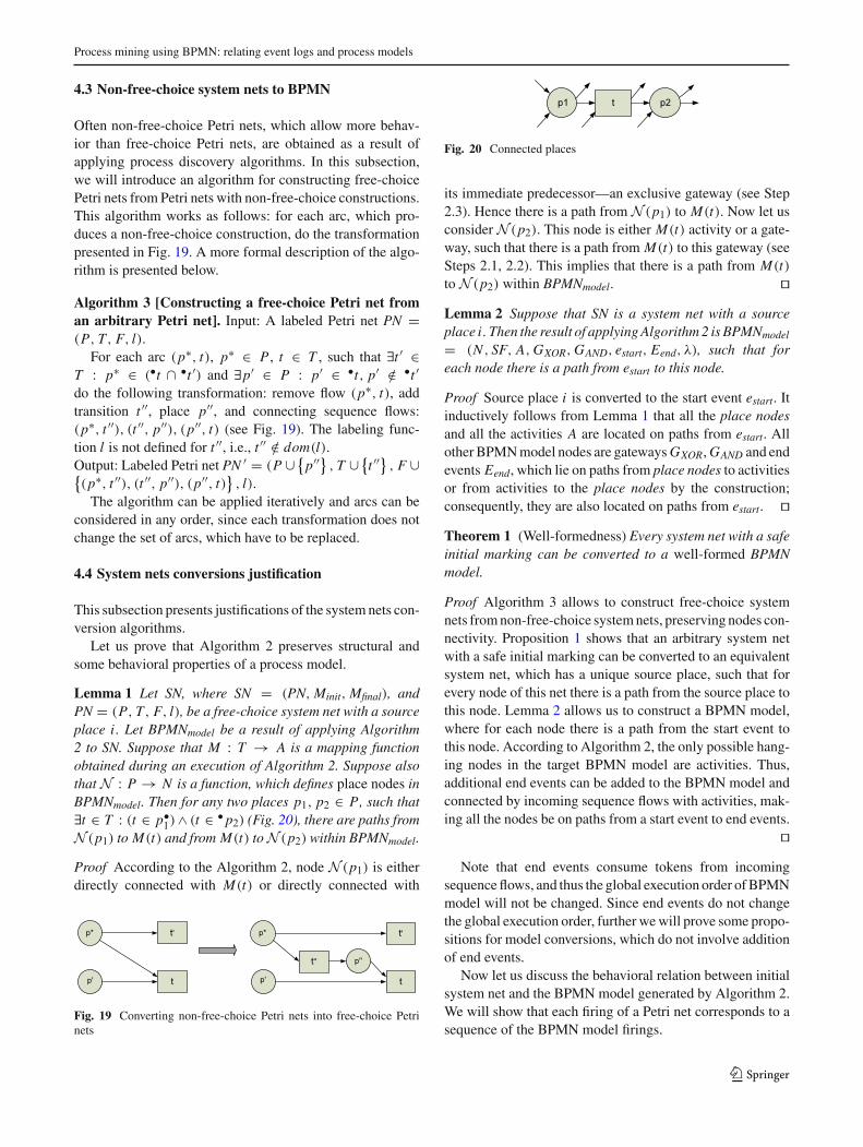
Often non-free-choice Petri nets, which allow more behav-ior than free-choice Petri nets, are obtained as a result ofapplying process discovery algorithms. In this subsection,we will introduce an algorithm for constructing free-choicePetri nets from Petri nets with non-free-choice constructions.This algorithm works as follows: for each arc, which pro-duces a non-free-choice construction, do the transformationpresented in Fig. 19. A more formal description of the algo-rithm is presented below.
Algorithm 3 [Constructing a free-choice Petri net froman arbitrary Petri net]. Input: A labeled Petri net PN =(P, T, F, l).
For each arc (p∗, t), p∗ ∈ P , t ∈ T , such that ∃t ′ ∈T : p∗ ∈ (•t ∩ •t ′) and ∃p′ ∈ P : p′ ∈ •t, p′ /∈ •t ′do the following transformation: remove flow (p∗, t), addtransition t ′′, place p′′, and connecting sequence flows:(p∗, t ′′), (t ′′, p′′), (p′′, t) (see Fig. 19). The labeling func-tion l is not defined for t ′′, i.e., t ′′ /∈ dom(l).Output: Labeled Petri net PN ′ = (P ∪ {
p′′} , T ∪ {t ′′
}, F ∪{
(p∗, t ′′), (t ′′, p′′), (p′′, t)}, l).
The algorithm can be applied iteratively and arcs can beconsidered in any order, since each transformation does notchange the set of arcs, which have to be replaced.
4.4 System nets conversions justification
This subsection presents justifications of the systemnets con-version algorithms.
Let us prove that Algorithm 2 preserves structural andsome behavioral properties of a process model.
Lemma 1 Let SN, where SN = (PN, Minit, Mfinal), andPN = (P, T, F, l), be a free-choice system net with a sourceplace i . Let BPMNmodel be a result of applying Algorithm2 to SN. Suppose that M : T → A is a mapping functionobtained during an execution of Algorithm 2. Suppose alsothatN : P → N is a function, which defines place nodes inBPMNmodel. Then for any two places p1, p2 ∈ P, such that∃t ∈ T : (t ∈ p•
1)∧ (t ∈ • p2) (Fig. 20), there are paths fromN (p1) to M(t) and from M(t) toN (p2) within BPMNmodel.
Proof According to the Algorithm 2, node N (p1) is eitherdirectly connected with M(t) or directly connected with
Fig. 19 Converting non-free-choice Petri nets into free-choice Petrinets
Fig. 20 Connected places
its immediate predecessor—an exclusive gateway (see Step2.3). Hence there is a path from N (p1) to M(t). Now let usconsider N (p2). This node is either M(t) activity or a gate-way, such that there is a path from M(t) to this gateway (seeSteps 2.1, 2.2). This implies that there is a path from M(t)to N (p2) within BPMNmodel. ��Lemma 2 Suppose that SN is a system net with a sourceplace i . Then the result of applyingAlgorithm2 is BPMNmodel
= (N , SF, A,GXOR,GAND, estart, Eend, λ), such that foreach node there is a path from estart to this node.
Proof Source place i is converted to the start event estart. Itinductively follows from Lemma 1 that all the place nodesand all the activities A are located on paths from estart. Allother BPMNmodel nodes are gatewaysGXOR,GAND and endevents Eend, which lie on paths from place nodes to activitiesor from activities to the place nodes by the construction;consequently, they are also located on paths from estart. ��Theorem 1 (Well-formedness) Every system net with a safeinitial marking can be converted to a well-formed BPMNmodel.
Proof Algorithm 3 allows to construct free-choice systemnets fromnon-free-choice systemnets, preserving nodes con-nectivity. Proposition 1 shows that an arbitrary system netwith a safe initial marking can be converted to an equivalentsystem net, which has a unique source place, such that forevery node of this net there is a path from the source place tothis node. Lemma 2 allows us to construct a BPMN model,where for each node there is a path from the start event tothis node. According to Algorithm 2, the only possible hang-ing nodes in the target BPMN model are activities. Thus,additional end events can be added to the BPMN model andconnected by incoming sequence flows with activities, mak-ing all the nodes be on paths from a start event to end events.
��Note that end events consume tokens from incoming
sequence flows, and thus the global execution order ofBPMNmodel will not be changed. Since end events do not changethe global execution order, further wewill prove some propo-sitions for model conversions, which do not involve additionof end events.
Now let us discuss the behavioral relation between initialsystem net and the BPMN model generated by Algorithm 2.We will show that each firing of a Petri net corresponds to asequence of the BPMN model firings.
123

A. A. Kalenkova et al.
(a)
(b)
Fig. 21 Initial markings
Theorem 2 (Weak similarity)Let SNbea free-choice systemnet with a source place i , where SN = (PN, Minit, Mfinal),PN = (P, T, F, l). Let BPMNmodel be a result of applyingAlgorithm 2 to SN, M : T → A is the mapping function. LetTS = (S, E, B, sin), TS ′ = (S′, E, B ′, s′
in) be reachabilitygraphs of SN and BPMNmodel, respectively. There exist weaksimulation relations R and R′ from TS to TS ′ and from TS ′to TS, respectively, such that:
1. (u, v) ∈ R iff ∀p ∈ P : u(p) = v(F(p)),2. if (u, v) ∈ R then (v, u) ∈ R′,3. ∀v ∈ S′∃v′ ∈ S′ : (v
∗→ v′)∧(∃u′ ∈ S : (u′, v′) ∈ R). Inother words, from each state v ∈ S′ it is always possibleto reach some state v′ ∈ S′, which is in the relation Rwith some state u′ ∈ S.
But it is not guaranteed that a weak bisimulation relationexists.
Proof Let us prove the existence ofweak simulation relationsR and R′ between TS and TS ′ inductively on pairs of statesu ∈ S, v ∈ S′ such that ∀p ∈ P : u(p) = v(F(p)).
Induction basis.
1. Pairs (sin, s′in) and (s′
in, sin) belong to R and R′, respec-tively, by the definition of a weak simulation relation.Both variants for initial markings of SN and BPMNmodel
are presented in Fig. 21. Tokens in Fig. 21 are repre-sented by black dots. As can be seen ∀p ∈ P : sin(p) =s′in(F(p)). For the proof of condition 3. see the Inductionstep.
2. Let us prove that there is no weak bisimulation relationbetween TS and TS ′. Suppose there is such a relation R′′(Fig. 22), then by the definition (s′
in, sin) ∈ R′′.
Fig. 22 Construction of a weak bisimulation relation
For variant b. it holds that exists v ∈ S′, such that s′in
τ→ v,and M(t) is enabled in v. The only state in TS, to whichthere is a transition from sin labeled by τ , is sin itself, thus(sin, v) ∈ R′′. State sin has at least one outgoing transitionlabeled with l(t ′), such that t ′ �= t . Suppose that l(t) �= l(t ′),thenwe get a contradiction, since v does not have an outgoingtransition labeled by l(t ′).
Induction step.
1. Now let us consider state u ∈ S (Fig. 23)By the induction hypothesis, there exists a state v inTS ′ (amarking of BPMNmodel), such that (u, v) ∈ R (Fig. 24).Furthermore, by the induction hypothesis the followingcondition holds: ∀p ∈ P : u(p) = v(F(p)), i.e., eachplace and its corresponding place flow contain the samenumber of tokens. Note that more than one token canappear in a place.Now let us show that if TS has a transition from stateu, TS ′ has a corresponding sequence of transitions from
state v, i.e., ∃v′′′ : vl(t)�⇒v′′′ and ∀p ∈ P : u′(p) =
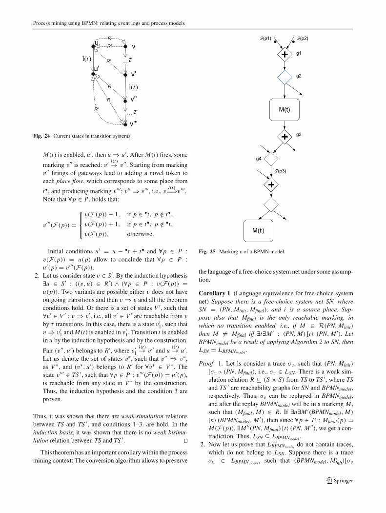
v′′′(F(p)). Thus, (u′, v′′′) will belong to R. State v ofBPMNmodel is presented in Fig. 25.Note that we consider the most general case, which rep-resents all the routing elements. The remaining cases canbe treated similarly. The gateway g1 is enabled in mark-ing v (by the construction, since t is enabled in u) and canfire, producing a novel marking, in which firing g2 yieldsM(t) being enabled. Let us call the marking, in which
Fig. 23 Marking u of a system net
123
Process mining using BPMN: relating event logs and process models
Fig. 24 Current states in transition systems
M(t) is enabled, u′, then u ⇒ u′. After M(t) fires, some
marking v′′ is reached: v′ l(t)→ v′′. Starting from markingv′′ firings of gateways lead to adding a novel token toeach place flow, which corresponds to some place from
t•, and producing marking v′′′: v′′ ⇒ v′′′, i.e., v l(t)�⇒v′′′.Note that ∀p ∈ P , holds that:
v′′′(F(p)) =
⎧⎪⎨⎪⎩
v(F(p)) − 1, if p ∈ •t, p /∈ t•,v(F(p)) + 1, if p ∈ t•, p /∈ •t,v(F(p)), otherwise.
Initial conditions u′ = u − •t + t• and ∀p ∈ P :v(F(p)) = u(p) allow to conclude that ∀p ∈ P :u′(p) = v′′′(F(p)).
2. Let us consider state v ∈ S′. By the induction hypothesis∃u ∈ S′ : ((v, u) ∈ R′) ∧ (∀p ∈ P : v(F(p)) =u(p)). Two variants are possible either v does not haveoutgoing transitions and then v ⇒ v and all the theoremconditions hold. Or there is a set of states V ′, such that∀v′ ∈ V ′ : v ⇒ v′, i.e., all v′ ∈ V ′ are reachable from v
by τ transitions. In this case, there is a state v′1, such that
v ⇒ v′1 and M(t) is enabled in v′
1. Transition t is enabledin u by the induction hypothesis and by the construction.
Pair (v′′, u′) belongs to R′, where v′1l(t)→ v′′ and u l(t)→ u′.
Let us denote the set of states v∗, such that v′′ ⇒ v∗,as V ∗, and (v∗, u′) belongs to R′ for ∀v∗ ∈ V ∗. Thestate v′′′ ∈ TS ′, such that ∀p ∈ P : v′′′(F(p)) = u′(p),is reachable from any state in V ∗ by the construction.Thus, the induction hypothesis and the condition 3 areproven.
Thus, it was shown that there are weak simulation relationsbetween TS and TS ′, and conditions 1–3. are hold. In theinduction basis, it was shown that there is no weak bisimu-lation relation between TS and TS ′. ��
This theoremhas an important corollarywithin the processmining context: The conversion algorithm allows to preserve
Fig. 25 Marking v of a BPMN model
the language of a free-choice system net under some assump-tion.
Corollary 1 (Language equivalence for free-choice systemnet) Suppose there is a free-choice system net SN, whereSN = (PN, Minit, Mfinal), and i is a source place. Sup-pose also that Mfinal is the only reachable marking, inwhich no transition enabled, i.e., if M ∈ R(PN, Minit)
then M �= Mfinal iff ∃t∃M ′ : (PN, M) [t〉 (PN, M ′). LetBPMNmodel be a result of applying Algorithm 2 to SN, thenLSN = LBPMNmodel .
Proof 1. Let is consider a trace σv , such that (PN, Minit)
[σv � (PN, Mfinal), i.e., σv ∈ LSN. There is a weak sim-ulation relation R ⊆ (S × S) from TS to TS ′, where TSand TS ′ are reachability graphs for SN and BPMNmodel,respectively. Thus, σv can be replayed in BPMNmodel,and after the replay BPMNmodel will be in a marking M ,such that (Mfinal, M) ∈ R. If ∃n∃M ′(BPMNmodel, M)
[n〉 (BPMNmodel, M ′), then since ∀p ∈ P : Mfinal(p) =M(F(p)), ∃M ′′(PN, Mfinal) [t〉 (PN, M ′′), we get a con-tradiction. Thus, LSN ⊆ LBPMNmodel .
2. Now let us prove that LBPMNmodel do not contain traces,which do not belong to LSN. Suppose there is a traceσv ∈ LBPMNmodel , such that (BPMNmodel, M ′
init)[σv
123

A. A. Kalenkova et al.
Fig. 26 Splitting non-free-choice construction
� (BPMNmodel, M), where M ′init is an initial mark-
ing of BPMNmodel. Theorem 2 states that there existsBPMNmodel marking M ′, such that (M ⇒ M ′) ∧ (∃M ′′ :(M ′′, M ′) ∈ R), where M ′′ is a marking of SN. By thedefinition of BPMN model language, no node can fireat the marking M , thus M = M ′, and (M ′′, M) ∈ R.We get that M ′′ is also a state (SN marking) withoutoutgoing transitions, otherwise M is not a final mark-ing of a BPMNmodel, since (M ′′, M) ∈ R. Thus, σv :(SN, Minit)[σv � (SN, M ′′), and σv ∈ LSN. ��Now let us compare behavioral properties of non-free-
choice Petri nets and corresponding free-choice Petri netsconstructed by Algorithm 3.
Theorem 3 (Non-free-choice Petri nets conversion) LetPN = (P, T, F, l) be an arbitrary labeled Petri net, andPN ′ = (P ′, T ′, F ′, l) be a result of applying Algorithm 3 toPN. Let TS = (S, E, B, sin) and TS ′ = (S′, E, B ′, s′
in) bereachability graphs of PN and PN ′, respectively. Then thereareweak simulation relations fromTS to TS ′, and fromTS ′ toTS. But it is not guaranteed that a weak bisimulation relationexists.
Proof Let us define weak simulation relations R and R′between TS and TS ′ in such a way that for every two statess ∈ S and s′ ∈ S′ if ∀p ∈ P : s(p) = s′(p), then (s, s′)belongs to R and (s′, s) belongs to R′. Let us consider a placep∗ ∈ P (Fig. 26), such that ∃t, t ′ ∈ T : p∗ ∈ (•t ∩ •t ′) and∃p′ ∈ P : p′ ∈ •t ′, p′ /∈ •t .
For this place, the output flow will be modified accordingto Algorithm 3. Let us consider u - a marking ofPN: u(p∗) ≥1 and construct fragments of reachability graphs for PN andPN ′, containing the marking u and a corresponding markingof PN ′ - v : ∀p ∈ P : v(p) = u(p) (Fig. 27).
Fig. 27 Simulation of non-free-choice net by the corresponding free-choice net
Suppose that t is enabled in u, and u′ is a state (PNmark-
ing) obtained after firing of transition t : ul(t)→ u′, then t is also
enabled in v, and v′ is a marking of PN ′, such that vl(t)→ v′,
then ∀p ∈ P : v′(p) = u′(p), and (u′, v′) ∈ R, (v′, u′) ∈ R.Now suppose that t ′ is enabled in u and can fire producing anovelmarking u′′′. For TS ′, there is a corresponding state v′′′,such that v
τ→ v′′ l(t ′)→ v′′′, and ∀p ∈ P : v′′′(p) = u′′′(p).Pair (u′′′, v′′′) will belong to R, pairs (v′′′, u′′′), (v′′, u) willbelong to R′. Note that the state u can simulate v′′, since∀p ∈ P, p �= p∗ : u(p) = v′′(p), and thus, it includesbehavior allowed in v′′. The procedure of defining R andR′ can be considered for each transformation of PN, andthus weak simulation relations between TS and TS ′ can bederived.
There is no bisimulation relation, since there is no state,which bisimulates v′′. ��Corollary 2 (Language of non-free-choice system net) LetSN = (PN, Minit, Mfinal) be an arbitrary system net, wherePN = (P, T, F, l). Let us applyAlgorithm3 toPNandobtaina free-choice Petri net PN ′ = (P ′, T ′, F ′, l). Let us considera system net SN ′ = (PN ′, Minit, Mfinal) with the same initialand final markings (we can construct such a system net sinceP ⊆ P ′). Then LSN = LSN ′ .
Proof Let TS and TS ′ be reachability graphs of SN and SN ′,respectively. As it follows from Theorem 3 TS ′ simulates TS,and vice versa, also they have the same final marking Mfinal,thus LSN = LSN ′ . ��Corollary 3 (Language inclusion) Let us consider a systemnet SN = (PN, Minit, Mfinal), such that PN = (P, T, F, l),and ∀t�M : (PN, Mfinal) [t〉 (PN, M), i.e, there is no transi-tion enabled in Mfinal. Then let us apply Algorithm 3 and toobtain a free-choice system net SN ′ = (PN ′, Minit, Mfinal)
with the same initial and final markings. Suppose thatBPMNmodel is a result of applying Algorithm 2 to SN ′. ThenLSN ⊆ LBPMNmodel .
Proof Let TS, TS ′, TSBPMN be reachability graphs of SN,SN ′, and BPMNmodel, respectively. LSN = LSN′ by Corol-lary 2. According to Corollary 1 if SN′ does not contain anystate, in which no transition can be enabled, except Mfinal,then LSN ′ = LBPMNmodel . But under hypothesis of this corol-lary TS (and consequently TS ′) may contain states, in whichno transition can be enabled, and which are not final. Alsonote that SN ′ may contain additional states (see the proofof Theorem 3), which represent the reduced behavior of SN;among them theremay be stateswithout outgoing transitions.Hence, LBPMNmodel may contain additional traces. ��Corollary 4 (Language equivalence for empty final mark-ing) Suppose a BPMN model BPMNmodel was constructedfrom a system net SN = (PN, Minit, Mfinal), where PN =
123

Process mining using BPMN: relating event logs and process models
Fig. 28 Relations between languages for system nets and corre-sponding BPMN models. FC is a class of free-choice system nets.FNE—a class of system nets, for which no transitions are enabled infinal markings. A system net belongs to the class FE, iff the final mark-ing is the empty marking. FO is a class of system nets, for which theirfinal markings are the only markings with no transitions enabled
(P, T, F, l), using Algorithm 2. If ∀p ∈ P : Mfinal(p) = 0,then VBPMNmodel = LSN. In other words, the set of validsequences coincides with the language of the system net.
Proof As it follows from Theorem 2 for every marking M ofa system net SN, there is a marking M ′ in BPMNmodel, suchthat for every position p, holds that M(p) = M ′(F(p)) andvice versa. In a system net, such that for every node of thisnet there is a path from the source place to this node, and ina BPMN model no node can fire in an empty marking, andhence, the theorem is proven. ��
Fig. 28 summarizes theoretical results presented above: Itshows relations between languages of system nets and cor-responding BPMN models depending on the type of systemnets.
Note that if the initial system net contains transitions withno incoming arcs (unconnected transitions), these transitionswill be enabled in any reachable marking of this net. Suchnets do not meet the sufficient condition for the languageinclusion, i.e., some transitions are always enabled in thefinal marking.
5 From other process notations to BPMN models
In this section, process modeling formalisms other than Petrinets but relevant for process mining aremapped onto BPMN.Basic ideas of conversion algorithms will be given. First wewill present additional BPMN routing constructs, which arenaturally used in these conversions.
(a) (b)
Fig. 29 Additional gateway types a Inclusive gateway, b Exclusiveevent-based gateway
5.1 Additional BPMN routing constructs
Let us consider two additional BPMN gateway types spec-ified in [6]. Inclusive gateways (Fig. 29a) implement mul-tichoice and synchronized merge control flow patterns [36].An inclusive gateway is enabled in a current marking if someof the incoming sequence flows contain tokens, and it is notpossible to reach a marking from the current marking, inwhich another (currently empty) incoming sequence flowwill contain tokens, without firing this gateway. Note thatthe semantics of inclusive gateways is non-local. An enabledinclusive gateway may fire, adding one token to one or moreoutgoing sequence flows. The gateway presented in Fig. 29acan produce a token for one of the outgoing sequence flowsor for both of them.
Next, we consider event-based exclusive gateways, whichimplement the deferred choice control flow pattern [36].Like an ordinary exclusive gateway, an event-based exclusivegateway (Fig. 29b) is enabled if at least one of the incom-ing sequence flows contains at least one token. An exclusiveevent-based gateway produces a token to one of the outgoingsequence flows depending on the event, which first occurred.Thus, a gateway presented in Fig. 29b produces a token toa path marked with a first happened event (a receipt of aconcrete message or a timer event).
5.2 Transforming causal nets to BPMN models
Causal nets are known to be suitable for the representa-tion of discovered process models. They are often used for
Fig. 30 Causal net of a booking process
123

A. A. Kalenkova et al.
Fig. 31 BPMN model constructed from the causal net example(Fig. 30)
process mining (see e.g., the Heuristic miner [26]), but tendto be unclear for the majority of process analysts. Althoughan algorithm for the conversion of causal nets to Petri netswas already presented in [10], conversions from causal netsto BPMN models should take into account the free-choicenature of BPMN models.
Causal nets are represented by activities and their bind-ings: Each activity has a set of input and a set of outputbindings (pre- and post-conditions). Let us consider a causalnet of a booking process shown in Fig. 30.
The start activity register has only empty input binding.There are three possible output bindings for this activ-ity: {book f light}, {bookhotel} and {book f light, bookhotel}. These bindings imply that activity register is fol-lowed by activity book f light , or activity book hotel, oractivities book f light and book hotel. The end activitypay has an empty output binding and three possible inputbindings, i.e., activity pay is preceded by book f light andbook hotel activities, or book f light activity, or book hotelactivity.
While each activity of a causal net is converted to a BPMNmodel activity, bindings are represented in terms of gateways.If someactivity hasmultiple input (output) bindings, a specialexclusive gateway is created, if some binding contains morethan one element, a parallel gateway should be added. In casecausal net hasmany start or end nodes, unique start/end nodesare added to simplify the conversion to a BPMN model.
The result of the causal net (Fig. 30) conversion is pre-sented in Fig. 31.
It is important to mention that causal nets provide declar-ative description of the process behavior, while BPMNpresented in Fig. 31 has a local firing rules semantics. Thus,potentially “unsound” BPMN models may be obtained as a
Fig. 32 BPMN model with inclusive gateways
result of conversion. Inclusive gateways can be exploited toobtain simpler models. Fig. 32 shows how the initial causalnet can be represented as a BPMN diagram using inclusivegateways.
5.3 Converting process trees to BPMN models
Process trees are often obtained as a result of applyingprocess discovery algorithms (e.g., Inductive miner [25] orGenetic miner [37]). In this subsection, basic transforma-tions for constructing a BPMN model from a given processtree will be proposed. Although process trees can be repre-sented as system nets, and system nets can be converted toBPMN models using algorithms introduced above, a directconversion algorithm gives an ability to consider additionalperspectives during the conversion. Moreover, the BPMNstandard natively supports such modeling elements as inclu-sive gateways and exclusive event-based gateways. Hence,there is no need to convert these constructions to problem-atic, unreadable process models.
Process trees were proposed in [25] and defined as directacyclic graphs with branch and leaf nodes. Each branch nodehas outgoing edges and is considered to be an operator node,
Table 2 Process tree to BPMN conversion
123

Process mining using BPMN: relating event logs and process models
Fig. 33 A Petri net discovered by the Inductive miner from the event log
Fig. 34 A BPMN model obtained from the Petri net
and leaf nodes do not have outgoing edges and stand foratomic activities.
Transformation rules are applied inductively, starting fromthe root node. For each branch node, the transformationdepends on a node type and each leaf node is transformed toan activity or BPMN model event. We consider the follow-ing basic operators: sequence, exclusive/inclusive/deferred(event-based) choice, exclusive/deferred (event-based) loopand parallel execution. Transformation rules for each type ofa branch node are presented in Table 2. Note that for eachexclusive event-based gateway, the types of the following
events are specified by an additional information attached tothe corresponding branch node of the tree.
5.4 Example
In this subsection, we will show how the presented conver-sion techniques can be applied to discover BPMN modelsfrom real-life event logs. We took an event log generated byan Incident and Problem Management System from VolvoIT Belgium as an example. For this log, we have applied the
Fig. 35 A causal net discovered from the event log
123

A. A. Kalenkova et al.
Fig. 36 A BPMN model obtained from the causal net
Inductive miner [25] and have obtained a Petri net presentedin Fig. 33.
This Petri net was converted to a BPMN model presentedin Fig. 34.
This BPMNmodel looksmore compact, since empty tran-sitions can be omitted, and elements, such as activities, canbe connected with each other directly without using interme-diate elements. The analysis of cases when the conversionsproduce simpler models is presented in Sect. 9. A causalnet constructed from this log by the Heuristic miner [26] ispresented in Fig. 35.
The causal net can be converted to a BPMNmodel as well(Fig. 36). Note that this BPMN model explicitly representsall routing constructions by means of inclusive and exclusivegateways.
In Sects. 4 and 5, we have shown multiple ways toconstruct BPMN models from event logs using conversions(refer to Fig. 3 for the overall picture).
In the remainder,weonly consider processmodelswithoutadditional routing constructs (inclusive gateways and event-based exclusive gateways). The reason is that we need toconvert BPMN models to classical Petri nets for replay.
6 BPMN model simplification
In this subsection, BPMN model transformations are pre-sented. These transformations allow us to reduce the size oftarget BPMN models. Similar Petri nets and YAWL reduc-tion rules have already been presented in [38–40] and can beapplied to BPMN constructions as well.
1. Removing silent activities. In contrast to Petri nets,BPMN models allow connecting arbitrary activities and
BPMN node BPMN node
BPMN node BPMN node
Fig. 37 Reducing gateways of the same type
Fig. 38 Removing silent activities
gateways, and thus activities, which are not labeled, maybe removed (Fig. 38).Note that all the activities constructedduring an executionof Algorithm 2 have exactly one incoming and exactlyone outgoing sequence flow.
2. Reducing gateways. Sequential gateways of the sametype, serving as join and split routers, can be reduced(Fig. 37).
3. Merging activities and gateways. According to thesemantics of BPMN, activities can be merged withpreceding and following gateways of the right type(Fig. 39).
7 Mapping conformance and performance infoonto BPMN models
Processmining is not limited to discovery, but also offers con-formance checking and enhancement techniques. To applyexisting replay methods, which will allow us to obtaindetailed conformance and performance information, the ini-tial BPMNmodel should first be converted to a Petri net, andafter that this Petri net can be analyzed using existing tech-niques for Petri nets. Note that BPMN models presented inthis section are based on the core subset of BPMNmodelingelements.
Fig. 39 Merging activitieswith preceding exclusive join and followingparallel split gateways
123

Process mining using BPMN: relating event logs and process models
... ...
...
......
... ...
a a
...
Fig. 40 BPMN to Petri net conversion patterns
7.1 Converting BPMN models to Petri nets
BPMN models based on the core subset of BPMN mod-eling elements and can be considered as workflow graphs.Every node of a workflow graph can be simply converted toa corresponding Petri net pattern (Fig. 40) by the algorithms,presented in [22,23].
Note that according to [23] some preliminary transforma-tions should be applied to a BPMN model: Each gatewayand activity, containing multiple inputs and outputs, shouldbe splitted. Also note that this basic conversion preservessemantics and guarantees bisimilarity between a BPMNmodel and a target Petri net due to the correspondencebetween BPMN sequence flows and workflow net places:Map : SF → P , i.e., for each sequence flow of the BPMNmodel, there is a corresponding place in the target Petri net.The proof of bisimulation is straightforward.
7.2 Mapping conformance and performance info
The bisimulation relation defines a mapping between statesof an initial BPMNmodel and a target Petri net, and gives usan ability to visualize performance and conformance infor-
bookhotel
book flight
getinsurance
paysf1 sf2
sf3
sf4
sf5
sf6
sf7
sf8
sf9 sf10register
Fig. 41 A BPMN of a booking procedure
mation, which is attached to some states of the Petri net,within the initial BPMN model.
To give an example, which shows how a conformanceinformation can be visualized within a BPMN diagram,we have to introduce the notion of alignment. Alignmentestablishes log and model similarities and discrepancies bydefining correspondence between moves on log and moves(firings) on model.
Let AL be a set of log events. Let also PN = (P, T, F, l)be a labeled Petri net, where l : T � AM , and AM is aset of model events. Let � be a special event, such that�/∈ (AL ∪ AM ).
Alignment step is a pair (x, y):
– (x, y) is a move on log if x ∈ AL , y =�,– (x, y) is a move on model if x =�, y ∈ AM ,– (x, y) is a move in both if x ∈ AL , y ∈ AM ,– (x, y) is an illegal move if x =�, y =�.
An alignment is a sequence of alignment steps that are notillegal moves.
Now let us consider a BPMNmodel of a booking process(Fig. 41).
Let us apply the conversion algorithm to obtain a Petri netwith places, corresponding to BPMN sequence flows. Theresult is shown in Fig. 42.
To illustrate enhancement of a process model with confor-mance and performance information, an event log consisting
book hotel
book flight
get insurance
pay
M(sf1)
M(sf2)
M(sf3)
M(sf4)
M(sf5)
M(sf6)
M(sf7)
M(sf8)
M(sf9)
M(sf10)
register
Fig. 42 A Petri net constructed from the BPMN model presented inFig. 41
123

A. A. Kalenkova et al.
Table 3 An event log of a booking process with cancelation
Case ID Event name Timestamp
1 Register (r) 2014-12-24 09:30:01:727
1 Book flight (bf ) 2014-12-24 09:43:23:353
1 Book hotel (bh) 2014-12-24 09:52:14:252
1 Cancel insurance (ci) 2014-12-24 09:52:20:732
1 Pay (p) 2014-12-24 10:04:24:754
of only one trace, containing insurance cancelation event, isconsidered (Table 3).
To construct an alignment, this log should be representedas a multiset of traces:
L =[〈register, book f light, book hotel,
cancel insurance, pay〉1].
The result of application of the algorithm [41], whichfinds an optimal (with the minimal number of log onlyand model only moves) alignment, is presented below (thenames of events are represented by their first letters, firingof silent transitions are denoted as τ ). The first row rep-resents log moves, while the second row stands for modelfirings:
γ = � r � bf � bh ci � pτ r τ bf gi bh � τ p
Such alignments can be used to enhance existing BPMNmodels with conformance information (Fig. 43).
Note that the relation between states of the models allowsus to attach log move information to sequence flows, whichcorrespond to a concrete state of theBPMNmodel—the state,in which log move is performed.
This BPMN model can be enriched with a performanceinformation (such as activity execution times) obtained as aresult of alignment-based replay (Fig. 44).
Note that different types of performance information, suchas average, minimal, maximal, relative execution times, canbe added to a diagram.
bookhotel
book flight
getinsurance
paysf1 sf2
sf3
sf4
sf5
sf6
sf7
sf8
sf9 sf10register
Log only move: cancel insurance
Model only move
Fig. 43 A BPMN model annotated with conformance information
bookhotel
book flight
getinsurance
paysf1 sf2
sf3
sf4
sf5
sf6
sf7
sf8
sf9 sf10register
13 min, 21 sec
22 min, 13 sec
12 min, 10 sec
Fig. 44 A BPMN model annotated with performance information
8 Tool support
The techniques presented in this paper have all been imple-mented in ProM, an open source framework for processmining. Let us consider BPMN packages architecture andtheir functionality in ProM (Fig. 45).
The core BPMN package provides basic interfaces forworking with BPMN models, including import and exportof BPMN diagrams in BPMN XML [6] and XPDL 2.2 [42]formats. The BPMN conversions package depends on thecore BPMN package and provides the ability to convert Petrinets, causal nets [10] and process trees [11] to BPMN, thussupporting the discovery of BPMN models. Besides that theresource and the data flow perspectives can be discovered aswell: Data Petri nets obtained using the data-aware processmining algorithm [28] can be used to create BPMN modelswith data perspective, and process treeswith resources can be
ProM
BPMN Analysis package
BPMN Conversions
package
BPMN package
«call»Replay plugins
«call»
BPMN modeling tool
Import/export of BPMN diagrams in BPMN XML 2.0
and XPDL 2.2 formats
«import» «import»
Fig. 45 BPMN packages architecture
123

Process mining using BPMN: relating event logs and process models
converted to BPMN model with lanes. The BPMN Analysispackage is constructed on top of the core BPMN, and theBPMN conversions packages and its plugins can be usedto enhance BPMN models with additional conformance andperformance information.
To illustrate this,we consider twomain use cases forwork-ing with BPMN in ProM.
Use case 1 (Discovering BPMN processes): The user dis-covers a BPMN model by applying discovery and BPMNconversions plugins, and then this model can be exported toan external BPMN modeling or execution tool (Fig. 46).
Use case 2 (Analyzing BPMN processes): The user loadsa BPMN model from an external BPMN modeling tool, andthen, by applying the BPMN Analysis package, it convertsthis model into a Petri net, replays a log to obtain con-formance and performance information, and enhances theBPMN diagram with this information (Fig. 47).
More details about the functionality of the BPMN pack-ages in ProM can be found at [43].
9 Case studies
In this section,we present case studies based on the event logsproduced by information systems from different domains.
Fig. 46 Discovering a BPMN model with data
Fig. 47 Analysis of a BPMN model
Firstwe consider a complex ticket reservation system fromthe traveling and transportation domain. This system belongsto a class ofComputerReservation Systems (CRS) and is usedfor booking all types of touristic products such as hotels,flights, cars, excursions, activities, trains, etc. It integratesmultiple Global Distribution Systems (GDS) for pre-sales(search, reservation) and sales (book, pay) processes. Thesystem can be accessed by normal customers through a Webinterface or by expert users, e.g., travel agency or system sup-port, through a special rich client interface. Independentlyof the client interface, calls to the backend of the systemare logged in order to track the system state and perfor-mance, to gather statistics and to analyze the user behaviorand make estimations and predictions.5 These logs containthe timestamps, identifiers of the business cases (unique iden-tifier of the reservation) and also different business attributesdescribing user operations (e.g., search, quote, book, pay),travel directions (e.g., origin, destination, booking code),traveling time (e.g., start and end date). For our experiments,
5 These logs exclude user and commercial sensible information likenames, credit cards and invoices.
123

A. A. Kalenkova et al.
Table 4 Event log from a CRSReservation ID Event name Timestamp Booking code Notification
390234516 T1-HF-H:TES 2013-12-18 08:36:00:570 BER
390234516 M55Type010Rsp-034 2013-12-18 08:36:04:717 998
390234516 T3-HF-H:HH004 2013-12-18 08:36:09:337 BER
390234516 M52Rsp 2013-12-18 08:36:09:337 998
390235717 T1-BA-H:TES 2013-12-18 08:36:12:155 BER45010 DH
390235717 M52Rsp 2013-12-18 08:36:18:397 712
we took a log of the ticket reservation system, which contains94 cases, 50 event names, and describes the system behaviorduring 4h of its work. This event data are perfectly suitablefor applying process mining, since we identify the case byreservation id, event names by a subset of business attributesand order of events by a timestamp.
The other system being analyzed is a Tracker System (TS)used for management of kanban and scrum software devel-opment processes. The history of the system usage containsshort traces (the average number of events per trace is 3.5).Each trace can be identified by a unique number, it cor-responds to a concrete task for developers and representsa sequence of task states, such as “Open,” “In Progress,”“Resolved,” “Reopened” and “Closed.” These task states are
considered as event names, and timestamps are used to orderthem.
Event logs produced by six different anonymous munic-ipalities [44,45] within the CoSeLoG project in the Nether-lands were analyzed as well. These event logs containinformation about executions of a permit application process.The original event logs were reduced in order to speed up thediscovery techniques applied: The number of traces for thesesix logs varies from 17 to 324, and the number of differentevent names is 22 for the log, which contains receiving phaseonly, and between 69 and 176 for the other event logs. Forthe log corresponding to the receiving phase, the mean caseduration time is 3.1days, and for the other logs the mean caseduration time lies between 21.4days and 49.2weeks.
Fig. 48 A Petri net discoveredby the Alpha miner from theevent log
123

Process mining using BPMN: relating event logs and process models
Fig. 49 A BPMN model constructed from the Petri net presented in Fig. 48
9.1 Discovering BPMN models
In this subsection, we show fragments of the CRS log anddescribe models discovered from this log.
A short typical fragment of an event log is shown inTable 4. Every log entry contains fields such as reserva-tion id, an event name, a timestamp, a booking code anda notification. An event name is a shortcut built from a useroperation and of a product type, e.g., “T1-HF-H:TES”meansthat user does operation “search” for a product type “Hotel.”The booking code identifies the location, e.g., “BER” meansBerlin, Germany. Thus, in the example in Table 4 we showtwo reservations: “390234516” is a search for available hotelsin Berlin and “390235717” is a reservation for a double roomin a concrete hotel in Berlin.
Further in this subsection, we use different discovery(Heuristic [26], Alpha [12] and Inductive [25] miners) toconstruct process models from the event log. As a result ofapplying discovering methods, we obtain Petri nets, causalnets and process trees. All these models are converted toBPMN using algorithms presented before. The log of thebooking process was filtered: The parts, which contain onlypositive or only negative cases (cases with booking errorevents), were identified. Moreover, since the booking flightprocedure differs from other bookings, the log was also fil-tered by containing booking flight event.
Let us consider models constructed from a filtered logcontaining only positive traces without flight booking proce-dure6; Fig. 48 illustrates a Petri net discovered with Alphaminer[12] for this log.
The BPMN model constructed for the given Petri net(Fig. 48) by the conversion algorithm is shown in Fig. 49.
Note that in this case the amount of routing elements (gate-ways) in the BPMN model is comparable with the numberplaces of the initial Petri net, and the number of activitiescoincides with the number of transitions. Also note thatthanks to Algorithm 1 all the activities of the target BPMNmodel are on paths from the start event to end events.
Now let us consider a causal net (Fig. 50) discovered usingthe Heuristic miner [26]. Note that the start nodes and the endnodes are highlighted in green and red, respectively.
This causal net can be converted to a BPMN model(Fig. 51) using the conversion algorithm presented before.
The BPMN model reveals the operational semantics ofthe process. Fig. 50 is not explicitly showing the routingconstructions, but the BPMNmodel does. Now we will con-sider a process tree discovered by the Inductive miner [25](Fig. 52).
The corresponding Petri net is presented in Fig. 53.
6 All the models presented in this section are discovered using ProMframework
123

A. A. Kalenkova et al.
Fig. 50 A causal net discovered by Heuristic miner from the event log
The BPMN model constructed from the process tree bythe conversion algorithmdoes not contain any silent activities(Fig. 54). Moreover, the number of gateways is significantlyless than the amount of places in the corresponding Petri net(Fig. 53). Note that the process, discovered by the Inductiveminer, is compactly presented in terms of BPMN.
9.2 Comparative analysis of the models discovered
In this subsection, we make a comparative analysis ofprocesses models discovered from the event logs and corre-sponding BPMN models obtained as a result of conversionsusing various metrics [16]. We will consider the following
Fig. 51 A BPMN model constructed from the causal net presented in Fig. 50
123

Process mining using BPMN: relating event logs and process models
Fig. 52 A process tree discovered by the Inductive miner
metrics: the number of nodes, the diameter (the maximallength of a shortest path from a start node to a node of thegraph) and density (ratio of the total number of arcs to themaximum possible number of arcs of the graph). As statedin [16], all these metrics have a negative correlation with theprocess model understandability.
Different process mining algorithms give process modelswith different characteristics. Of course, the set of consid-ered process mining algorithms is far from complete. Butour aim is to analyze the conversion techniques, thuswise we
have selected algorithms, representing the entire classes ofdiscovery approaches, which produce process models withcertain properties. TheAlphamining algorithm is not tailoredtoward handling noisy real-life logs and discovers unstruc-tured process models; meanwhile, the Inductive miner dealswith noise and produces structured models. The Heuristicminer was chosen as a technique, which allows us to con-struct causal nets from event logs.
Let us consider a free-choice system net SN = (PN, Minit,
Mfinal), where PN = (P, T, F, l) is a labeled Petri net,
Fig. 53 A Petri net constructed from the process tree shown in Fig. 52
123

A. A. Kalenkova et al.
Fig. 54 A BPMN model, which corresponds to the process tree (Fig. 52)
and a BPMN model BPMNmodel = (N , A,GXOR,GAND,
estart, Eend, SF, λ), obtained by the conversion algorithmfrom this net. The number of activities equals to the num-ber of non-silent transitions: |A| = | {t ∈ T : t λ(t) �= τ } |.In the worst case, the number of gateways |GXOR ∪ GAND| iscomparable to the number of places plus the number of transi-tions : |P|+|T |, since every place can produce an XOR-join,and in the worst case, the number of AND-join gateways andthe number of XOR-split gateways are both comparable to�|T |/2�.Note thatAND-split gatewayswill be deleted duringthe simplification of the BPMNmodel. In the best case (for asequential control flow), a BPMNmodel will not contain anygateways. Also note that all the constructions produced dur-ing the transformation of arbitrary Petri nets to free-choicenets will contain only silent transitions and related places.
For a BPMN model constructed from a causal net, thenumber of activities equals the number of causal net activ-ities. The number of gateways is determined by input andoutput bindings of the activities.
A BPMN model constructed as a result of a process treeconversion contains activities corresponding to non-silentprocess tree leafs, and every branch node of the process treewill be converted to a routing construction of the BPMNmodel, containing zero (in the case of a sequential con-trol flow), one or more routing nodes. Note that somerouting nodes might be merged during the simplificationprocedure.
To estimate the number of nodes of process models dis-covered from the real-life event logs, let us consider Table 5.The rows in this and other tables are ordered by the numberof process models nodes.
The first column refers to the event logs used: six eventlogs, originating from municipal processes, of the CoSeLoGproject (denoted as CSLG1–CSLG6), the logs ofCSR (Com-puter Reservation System) with various types of filteringapplied7 and the logs of TS (Tracking system). Each of theother columns mentions the number of nodes of the initialprocess model constructed by a discovery algorithm and thenumber of nodes of the BPMN model obtained as a resultconversion (for Petri nets and BPMN models the number oftransitions, places and the number of activities, XOR gate-ways, AND gateways are specified, the values are separatedby a comma).
This table shows that the number of BPMN model nodesdepends on the properties of the initial Petri net: BPMNmodels constructed for structured Petri nets are more com-pact (see the Inductive miner column). This holds due tothe fact that BPMN language allows simplifications, suchas silent nodes deletion (structured models usually containsilent nodes) and gateways reduction, which is also applica-ble to structured nets, if some blocks can be merged. Fornon-structured Petri nets (see the Alpha miner column), the
7 By CSR1, CSR2, CSR3 and CSR4 we denote event logs of theComputer Reservation System, containing only positive cases and/orbooking flight event.
123

Process mining using BPMN: relating event logs and process models
Table 5 Number of nodes of process models discovered from the event logs
Log traces Heuristic miner(C-net/ BPMNa)
Alpha miner (Petrinetb/ BPMNa)
Inductive miner (Proc.tree/ Petri netb/BPMNa)
CSLG1 176/176,143,128 176,372/176,340,120 261/235,49/176,25,0
CSLG2 134/134,58,56 134,238/134,159,54 273/223,89 /134,42,0
CSLG3 93/93,58,70 93,198/93,153,42 219/173,78/93,35,0
CSLG4 75/75,49,52 75,143/75,101,33 151/120,50/75,21,0
CSLG5 68/68,58,58 68,181/69,159,55 84/77,9/68,3,0
CSR1 30/30,14,4 30,23/30,18,13 130/100,53/ 30,25,0
CSR2 30/30,14,5 30,13/30,5,7 102/81,43/ 30,20,0
CSR3 27/27,10,4 27,28/27,24,13 107/82,52/ 27,24,2
CSLG6 22/22,8,6 22,24/22,14,12 54/41,19/ 22,7,0
CSR4 21/21,6,4 21,23/21,18,11 88/ 67,41/ 21,18,0
TS 5/5,7,0 5,7/5,5,4 15 / 9,5 / 5,3,0
a For BPMN models, the number of activities, XOR gateways and AND gateways are specified, and the values are separated by a commab For Petri nets the number of transitions and places are specified and separated by a comma
number of BPMNmodel nodes is comparable or even greaterthan the number of nodes of the initial Petri net. Also accord-ing to the theoretical observations, the number of nodes of aBPMN model is not always lower than the number of nodesof the initial causal net, since BPMN models may have rout-ing nodes.
Similarly let us estimate the density of the models dis-covered (Table 6). Graph density is defined as D = |E |/(|V | ∗ (|V | − 1)), where E is a set of edges and V is a set ofnodes. Density shows the relation between the real numberof edges and the maximum possible number of edges in thegraph.
The density of the BPMN models constructed fromunstructured Petri nets is comparable with the density ofthese Petri nets (see the Alpha miner column). The density ofstructured Petri nets is larger than the density of correspond-
Table 6 Density of the models discovered
Log traces Heuristic miner(C-net/ BPMN)
Alpha miner(Petri net/BPMN)
Inductive miner(Petri net/BPMN)
CSLG1 0.01/0.004 0.005/0.004 0.005/0.01
CSLG2 0.01/0.005 0.005/0.005 0.005/0.01
CSLG3 0.02/0.01 0.01/0.01 0.005/0.02
CSLG4 0.02/0.01 0.01/0.01 0.01/0.02
CSLG5 0.02/0.005 0.005/0.005 0.01/ 0.02
CSR1 0.07/0.04 0.05/0.04 0.01/0.04
CSR2 0.07/0.04 0.03/0.05 0.01/0.04
CSR3 0.06/0.04 0.04/0.03 0.01/0.03
CSLG6 0.07/0.05 0.04/0.04 0.03/0.06
CSR4 0.08/0.05 0.05/0.04 0.01/0.04
TS 0.5/0.2 0.19/0.12 0.1 / 0.16
Table 7 Diameter of the processmodels discovered from the event logs
Log traces Heuristic miner(C-net/ BPMN)
Alpha miner(Petri net/BPMN)
Inductive miner(Petri net/BPMN)
CSLG1 12/24 17/21 37/14
CSLG2 39/53 49/42 76/23
CSLG3 23/38 37/26 71/23
CSLG4 25/32 39/34 56/16
CSLG5 18/35 13/17 16/5
CSR1 3/7 6/10 20/6
CSR2 3/7 5/7 8/9
CSR3 6/12 11/13 39/14
CSLG6 6/11 13/13 25/7
CSR4 5/8 10/11 41/12
TS 2/5 3/6 5/4
ing BPMN models (see the Inductive miner column) due toreductions applied in the case of structured processes. Thedensity of causal nets is certainly greater than the density ofcorresponding BPMN models, since novel gateways, whichconnect process activities, are added.
Now let us consider the diameter—the maximal lengthof a shortest path from a start node to a node of the graph.The results presented in Table 7 show that the statementsvalid for the number of nodes parameter are also true for thediameter: BPMN models corresponding to structured Petrinets are more compact than the initial models.
In this subsection, we have evaluated the discoveredprocess models using metrics, such as the number of nodes,the density and the diameter. The results show that the com-pactness of the result BPMN models depends considerablyon characteristics of the initial models.
123

A. A. Kalenkova et al.
Table 8 Characteristics of process models from the Signavio modelcollection
Number of nodes Density Diameter
Maximal 58.00 0.87 25
Mean 20.76 0.10 8
Minimal 6.00 0.00 1
Another important issue in the context of our practicalcase studies presented in this subsection was the understand-ability of the process mining output format. The softwarearchitects and designers of the touristic system were espe-cially interested in getting the results in the BPMN format.They were familiar with BPMN, and BPMN was also usedin the specification and design phases of the software prod-uct for documenting the typical touristic business processes.MoreoverBPMNexchange formats, such asBPMNXML[6]and XPDL 2.2 [42], give us an ability to integrate with a vari-ety of BPMNsupporting tools, and thus discovered processescan be analyzed, improved or even automated using externalenvironments. In addition BPMN offers great opportunitiesto add other perspectives, such as data and resource informa-tion, results of conformance and performance analysis. Thisway the analyst can obtain a holistic view on the processesdiscovered.
9.3 Comparing discovered and manually created BPMNmodels
To compare the models discovered from the event log withmanually created BPMN models, we analyzed the Signaviomodel collection, which contains a variety of BPMNmodelsfrom different domains. We took only flat models repre-sented by start and end events, tasks, gateways and sequenceflows. Currently the Signaviomodel collection contains 4900of such models. For these models, we calculated the struc-tural characteristics: number of nodes, density and diameter(Table 8).
Comparing these results with themeasurements presentedin the Tables 5 and 7, one may conclude that models drawnmanually (excluding models discovered from the small TSlog) are usually more compact than those, which were auto-matically discovered using the well-known discovery andconversion algorithms presented in this paper.
Also these observations show that BPMN models createdmanually have higher density than automatically discoveredBPMN models. The results obtained for the Signavio modelcollection are a consequence of the fact that business processanalysts and engineers are used to work with more struc-tured models, so an algorithm for subprocesses discoveryis needed. An algorithm for the construction of BPMN sub-processes basedon a log clustering andfilteringwas proposed
in [24]. However, more research is needed to compare hand-made and discovered models.
10 Conclusions and future work
This paper provides a solid basis for using BPMN in processmining. The results presented in the paper concentrate on thecontrol flow perspective, as it is usually considered to be themain perspective. It is the starting point for extending withadditional perspectives during an enhancement of the processmodel discovered from an event log.
In this paper, we used various control flow discovery algo-rithms. These produce Petri nets, causal nets, process trees,etc. Few algorithms produce directly a BPMNmodel. Hence,we developed various conversion algorithms tomine BPMN.Petri nets, process trees and causal nets discovered from areal-life event log were compared with the correspondingBPMN models on the basis of three process metrics. More-over, these metrics were applied to measure the differencebetween BPMN models, which were created by analysts,and BPMN models retrieved as a result of process discov-ery algorithms. An approach for enhancing a BPMN modelwith additional conformance and performance informationwas proposed as well.
The results presented in the paper can be used to retrieveBPMNmodels out of event logs and verify themagainst eventlogs. This work can be considered as a first step toward thedevelopment of more advanced process discovery methods,including novel perspectives.
As was shown in Sect. 9.3, more structured process mod-els are needed, and thus methods for subprocesses discoveryshould be introduced. In comparison with the approach pre-sented in [24], we plan to build a method on top of thedecomposition techniques [46–48] to obtain structural mod-els, preserving behavior recorded in an event log.
References
1. van der Aalst, W.M.P.: Process Mining—Discovery, Conformanceand Enhancement of Business Processes. Springer, Berlin (2011)
2. Mans, R.S., Schonenberg, M.H., Song, M., van der Aalst, W.M.P.,Bakker, P.J.M.: Application of process mining in healthcare: a casestudy in a Dutch hospital. In: Biomedical engineering systems andtechnologies. communications in computer and information sci-ence, vol. 25, pp. 425–438. Springer, Berlin (2009)
3. Mitsyuk, A.A., Kalenkova, A.A., Shershakov, S.A., van der Aalst,W.M.P.: Using processmining for the analysis of an e-trade system:a case study. Bus. Informatics 3, 15–23 (2014)
4. Trcka, N., Pechenizkiy, M.: From local patterns to global models:towards domain driven educational process mining. In: 9th Inter-national conference on intelligent systems design and applications(ISDA), pp. 1114–1119. IEEE Computer Society (2009)
5. IEEE task force on process mining: process mining manifesto. In:Business Process Management Workshops, Lecture Notes in Busi-ness Information Processing, vol. 99, pp. 169–194. Springer (2012)
123

Process mining using BPMN: relating event logs and process models
6. OMG: Business Process Model and Notation (BPMN), Version2.0. http://www.omg.org/spec/BPMN/2.0 (2011)
7. Muehlen, M.Z., Ho, D.T.: Service process innovation: a case studyof bpmn in practice. In: Proceedings of the proceedings of the 41stannualHawaii international conference on system sciences, HICSS’08, p. 372. IEEE Computer Society, Washington (2008)
8. Muehlen, M.Z., Recker, J.: How much language is enough?Theoretical and practical use of the business process modelingnotation. In: Proceedings of the 20th international conference onadvanced information systems engineering. CAiSE ’08, pp. 465–479. Springer, Berlin, Heidelberg (2008)
9. Recker, J.: Opportunities and constraints: the current struggle withBPMN. Business Process Manag. J. 16(1), 181–201 (2010)
10. van der Aalst, W.M.P., Adriansyah, A., van Dongen, B.F.: Causalnets: a modeling language tailored towards process discovery.In: CONCUR, Lecture Notes in Computer Science, pp. 28–42.Springer (2011)
11. van der Aalst,W.M.P., Buijs, J.C.A.M., van Dongen, B.F.: Towardsimproving the representational bias of process mining. In: IFIPinternational symposium on data-driven process discovery andanalysis (SIMPDA 2011). Lecture Notes in Business InformationProcessing, vol. 116, pp. 39–54. Springer, Berlin (2012)
12. van der Aalst,W.M.P.,Weijters, A.J.M.M.,Maruster, L.:Workflowmining: discovering process models from event logs. IEEE Trans.Knowl. Data Eng. 16(9), 1128–1142 (2004)
13. Cardoso, J., Mendling, J., Neumann, G., Reijers, H.A.: A discourseon complexity of processmodels. In: Proceedings of the 2006 inter-national conference on business process management workshops.BPM’06, pp. 117–128. Springer, Berlin (2006)
14. Latva-Koivisto, A.: Finding a complexity measure for businessprocess models Tech. rep, Helsinki University of Technology,Espoo, Helsinki (2001)
15. Laue, R., Gruhn, V.: Complexity metrics for business process mod-els. In: Business Information Systems, 9th international conferenceon business information systems, BIS 2006, pp. 1–12 (2006)
16. Sánchez-González, L., García, F., Mendling, J., Ruiz, F., Piattini,M.: Prediction of business process model quality based on struc-tural metrics. In: ER, Lecture Notes in Computer Science. vol.6412, pp. 458–463. Springer (2010)
17. van der Aalst, W.M.P., Adriansyah, A., van Dongen, B.F.: Replay-ing history on process models for conformance checking andperformance analysis. Wiley Interdiscp. Rev. Data Min. Knowl.Discov. 2(2), 182–192 (2012)
18. van der Aalst, W.M.P.: The application of Petri nets to workflowmanagement. J. Circuits Syst. Comput. 8(1), 21–66 (1998)
19. OMG: OMG Unified Modeling Language 2.5. OMG. http://www.omg.org/spec/UML/2.5/ (2013)
20. Kindler, E.: On the semantics of EPCs: a framework for resolvingthe vicious circle. In: International Conference onBusiness ProcessManagement (BPM 2004), Lecture Notes in Computer Science,vol. 3080, pp. 82–97. Springer (2004)
21. Mendling, J., van der Aalst,W.M.P.: Towards EPC semantics basedon state and context. In: Proceedings of fifth workshop on event-driven process chains (WI-EPK 2006), pp. 25–48. Gesellschaft fürInformatik, Bonn, Vienna (2006)
22. van der Aalst, W.M.P., Hirnschall, A., Verbeek, H.M.W.: An alter-native way to analyze workflow graphs. In: Proceedings of the14th international conference on advanced information systemsengineering (CAiSE’02), vol. 2348, pp. 535–552 (2002)
23. Favre, C., Fahland, D., Völzer, H.: The relationship between work-flow graphs and free-choice workflow nets. Inf. Syst. 47, 197–219(2015)
24. Conforti, R., Dumas, M., Garcia-Baneulos, L., La Rosa, M.:Beyond tasks and gateways: discovering BPMN models with sub-processes, boundary events and activity markers. In: International
conference in business process management (BPM), pp. 101–117.Springer, Haifa (2014)
25. Leemans, S.J.J., Fahland, D., van der Aalst, W.M.P.: Discoveringblock-structured process models from event logs: a constructiveapproach. In: Application and Theory of Petri Nets and Concur-rency, Lecture Notes in Computer Science. vol. 7927, pp. 311–329.Springer (2013)
26. Weijters, A.J.M.M., Ribeiro, J.T.S.: Flexible heuristics miner(FHM). In: IEEE symposium on computational intelligence anddata mining (CIDM 2011), pp. 310–317. IEEE, Paris, France(2011)
27. Weerdt, J.D., vanden Broucke, S.K.L.M., Caron, F.: Bidimen-sional process discovery for mining bpmn models. In: Fournier,F., Mendling, J. (eds.) Business Process Management Workshops,Lecture Notes in Business Information Processing, vol. 202, pp.529–540. Springer, (2014)
28. de Leoni, M., van der Aalst, W.M.P.: Data-aware process mining:discovering decisions in processes using alignments. In:ACMsym-posium on applied computing (SAC 2013), pp. 1454–1461. ACMPress (2013)
29. Burattin, A., Sperduti, A., Veluscek,M.: Businessmodels enhance-ment through discovery of roles. In: IEEE symposium on compu-tational intelligence and data mining, CIDM 2013, Singapore, pp.103–110 (2013)
30. Song, M., van der Aalst, W.M.P.: Towards comprehensive supportfor organizational mining. Decis. Support Syst. 46(1), 300–317(2008)
31. de Leoni, M., van der Aalst, W.M.P., van Dongen, B.F.: Data- andresource-aware conformance checking of business processes. In:BIS, Lecture Notes in Business Information Processing. vol. 117,pp. 48–59. Springer (2012)
32. van der Aalst, W.M.P., Rubin, V.A., Verbeek, H.M.W., van Don-gen, B.F., Kindler, E., Günther, C.W.: Process mining: a two-stepapproach to balance between underfitting and overfitting. Softw.Syst. Model. 9(1), 87–111 (2010)
33. Bergenthum, R., Desel, J., Lorenz, R., Mauser, S.: Process min-ing based on regions of languages. In: International conferenceon business process management (BPM 2007), Lecture Notes inComputer Science. vol. 4714, pp. 375–383. Springer (2007)
34. Carmona, J., Cortadella, J.: Processminingmeets abstract interpre-tation. In: ECML/PKDD 210, Lecture Notes in Computer Science,vol. 6321, pp. 184–199. Springer (2010)
35. Günther, C.W., van der Aalst, W.M.P.: Fuzzy mining: adaptiveprocess simplification based onmulti-perspectivemetrics. In: Inter-national conference on business processmanagement (BPM2007),Lecture Notes in Computer Science, vol. 4714, pp. 328–343.Springer (2007)
36. Russell, N., ter Hofstede, A.H.M., van der Aalst, W.M.P., Mul-yar, N.: Workflow control-flow patterns: a revised view. Tech.Rep. BPM-06-22, BPM Center. http://bpmcenter.org/wp-content/uploads/reports/2006/BPM-06-22.pdf (2006)
37. Buijs, J.C.A.M., van Dongen, B.F., van der Aalst, W.M.P.: AGenetic algorithm for discovering process trees. In: IEEECongresson evolutionary computation (CEC2012), pp. 1–8. IEEEComputerSociety (2012)
38. Desel, J., Esparza, J.: FreeChoice PetriNets. CambridgeUniversityPress, New York (1995)
39. Murata, T.: Petri nets: properties, analysis and applications. Proc.IEEE 77(4), 541–580 (1989)
40. Wynn, M., Verbeek, H., van der Aalst, W.M.P., Hofstede, A.,Edmond, D.: Reduction rules for YAWL workflows with cancella-tion regions and OR-join. Inf. Softw. Technol. 51(6), 1010–1020(2009)
41. Adriansyah, A., van Dongen, B.F., van der Aalst, W.M.P.: Confor-mance checking using cost-based fitness analysis. In: EDOC, pp.55–64. IEEE Computer Society (2011)
123

A. A. Kalenkova et al.
42. WFMC: XML Process Definition Language Version 2.2. In: Tech-nical Report WFMC-TC-1025, Workflow Management Coalition,Lighthouse Point, Florida, USA (2012)
43. Kalenkova,A.A., deLeoni,M., vanderAalst,W.M.P.:Discovering,analyzing and enhancing BPMNmodels using ProM. In: BusinessProcessManagement—12th International Conference, BPM2014,Haifa, Israel, September 7–11, 2014. Proceedings (2014). In press
44. Buijs, J.C.A.M.: Environmental Permit Application Process.CoSeLoG project (2014)
45. Buijs, J.C.A.M.: Receipt phase of an environmental permit appli-cation process. CoSeLoG project (2014)
46. van der Aalst, W.M.P.: A general divide and conquer approach forprocess mining. In: Federated conference on computer science andinformation systems (FedCSIS 2013), pp. 1–10 (2013)
47. Kalenkova, A.A., Lomazova, I.A.: Discovery of cancellationregionswithin processmining techniques. Fundam. Inform.133(2–3), 197–209 (2014)
48. Kalenkova, A.A., Lomazova, I.A., van der Aalst, W.M.P.: Processmodel discovery: A method based on transition system decompo-sition. In: Application and Theory of Petri Nets and Concurrency,Lecture Notes in Computer Science, pp. 71–90. Springer (2014)
AnnaA. Kalenkova was gradu-ated in appliedmathematics fromthe Lomonosov Moscow StateUniversity; in 2011 she com-pleted her PhD in the Com-puting Center of Russian Acad-emy of Sciences. Currently sheis working in the Laboratoryof Process Information SystemsHigher School of Economics,Moscow, Russian Federation asa senior researcher. Her maintopics of interest are Petri nets,workflow nets, business processmodeling languages, business
process management systems and process mining.
WilM. P. van der Aalst is a fullprofessor of Information Sys-tems at the Technische Univer-siteit Eindhoven (TU/e) wherehe is also scientific director ofthe Data Science Center Eind-hoven (DSC/e). His personalresearch interests include work-flow management, process min-ing, Petri nets, business processmanagement, process modeling,and process analysis.Wil van derAalst has published more than180 journal papers, 18 books (asauthor or editor), 400 refereed
conference/workshop publications, and 60 book chapters. He is a mem-ber of the Royal Netherlands Academy of Arts and Sciences, RoyalHolland Society of Sciences and Humanities, and Academia European.
Irina A. Lomazova is a Profes-sor at the Faculty of ComputerScience, National Research Uni-versity Higher School of Eco-nomics (Moscow,Russia), whereshe also heads the Laboratoryfor Process-Aware InformationSystems. Her research interestsinclude process modeling andanalysis, formal models of con-currency, Petri nets, and processmining.
Vladimir A. Rubin Duringmore than 14 years he has beenworking and researching in thearea of software engineering ina variety of projects in differ-ent consulting and technologycompanies (msg systems AG,Capgemini, sd&m, NetCracker)and scientific institutions in Ger-many, Russia, USA, Holland,and Switzerland. He graduatedin computer science from theMoscowStateUniversity ofRail-way Transport and completed hisPhD in a graduate school of
dynamic intelligent systems in Paderborn, Germany. Currently he isworking as an independent Lead IT Architect and Consultant in Frank-furt am Main, Germany.
123