process flow and steam gathering system - geoelec · process flow and steam gathering system . ......
TRANSCRIPT

Process flow and steam gathering system
Session VI
Elín Hallgrímsdóttir Paola Bombarda
Mannvit Politecnico di Milano
Postdam, April 18th, 2013

Presentation overview
• Presentations reviewing different cycles and design process
• Demonstration of thermodynamic models for different working cycles
• Calculated example showing methods used within geothermal steam gathering system design


Lindal diagram

Geothermal power generation

Geothermal in Iceland

Process flow
• A review of thermodynamic cycles used in geothermal energy production. Flash steam cycles with single flash and double flash as well as different binary cycles as ORC and Kalina Cycle are introduced and compared

Binary technology
Main features: • Power generation by means of closed
thermodynamic cycle
• Geothermal fluid loop and power cycle are completely separated
• Nearly zero emission plant
• Suitable for integration with other energy sources (solar, biomass, waste....)

Low enthalpy fluid gathering
• Doublet: (1 production well, 1 injection well) is the typical layout
• Triplet is also used
• Multi-well, with several modules is being discussed

The geothermal fluid loop
Power cycle
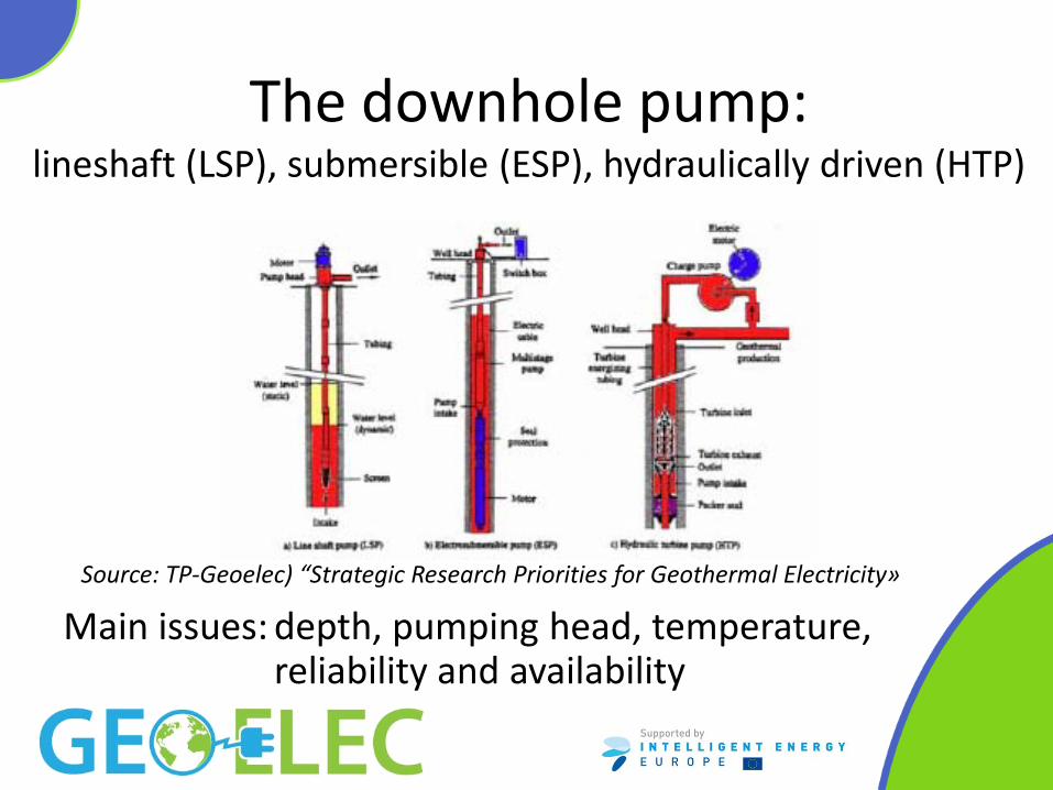
The downhole pump: lineshaft (LSP), submersible (ESP), hydraulically driven (HTP)
Main issues: depth, pumping head, temperature, reliability and availability
Source: TP-Geoelec) “Strategic Research Priorities for Geothermal Electricity»

Power cycle: the reference ideal cycle for all liquid heat source, with constant heat capacity
Entropy
η⋅= INQP Geothermal fluid reinjection temperature
Ambient temperature
T
Geothermal fluid inlet temperature
OUTQ
INQ REMIND: the cycle efficiency depends only on the geothermal source and ambient temperatures
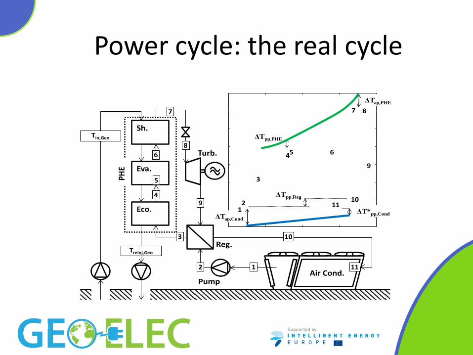
Power cycle: the real cycle
Turb.
Reg.
Pump
Eva.
Eco.
Sh.
Air Cond.
4
3
2 1
6
7
8
9
10
5
11
2
ΔTap,Cond
3
45 6
7 8
9
1011
PHE
Tin,Geo
Treinj,Geo
ΔT*pp,Cond
ΔTap,PHE
ΔTpp,PHE
ΔTpp,Reg
1

Concepts for binary cycle design
• Objectives: - high efficiency - => second law analisys: minimize second law
losses
- low cost, €/kW - => optimize component design
- Critical choice: the cycle working fluid

Concepts for binary cycle design The heat introduction process

ORC Cycle working fluid selection
• The fluid must be suitable for the selected geothermal source and plant size (Fluid critical temperature and pressure, molecular complexity are relevant)
• Hydrocarbons
• Refrigerants
• Others Important issues: environmental, toxicity, flammability

Cycle selection: simple or recuperative subcritical or supercritical

Kalina plant working fluid: ammonia-water mixture
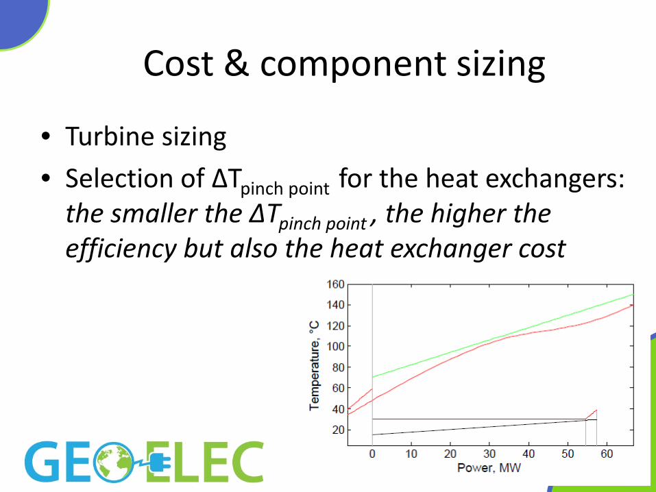
Cost & component sizing
• Turbine sizing
• Selection of ∆Tpinch point for the heat exchangers: the smaller the ∆Tpinch point , the higher the efficiency but also the heat exchanger cost

Component sizing and performance
Source: C. Pietra et al. 2010
Example for heat recovery case (Diesel engine)

Demonstration of model
• ORC preliminary evaluation http://www.turboden.eu/en/rankine/rankine-calculator.php

The plant power balance Net plant power = (turbine power – pump power) -auxiliaries power consumption

Binary plant performance

Back Pressure Steam Power Plant
Steam separator
Turbine Generator
G
Production wells Reinjection wells
Phigh
Plow
2 phase flow Vapor
Liquid

Back pressure unit - layout
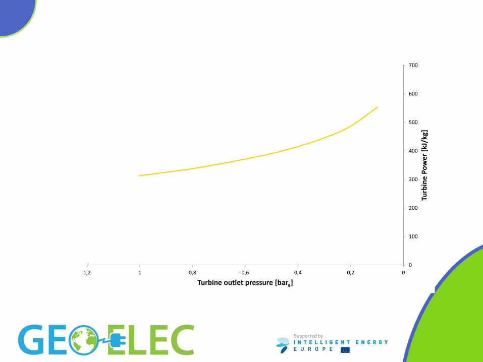
0
100
200
300
400
500
600
700
00,20,40,60,811,2
Turb
ine
Pow
er [k
J/kg
]
Turbine outlet pressure [bara]

Steam Power Plant with Condenser
G
Production wells
Geothermal fluid
Steam separator
Turbine
Condenser
Steam Generator
Silencer
Mist eliminator
Water
Condensate
Condensate
Cooling tower
Reinjection wells
Vacuum pump
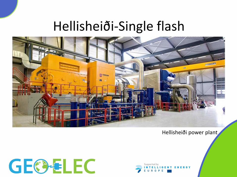
Hellisheiði-Single flash
Hellisheiði power plant

Steam Power Plant – Double Pressure
G
Production wells
Two phase flow Turbine - generator HP steam
LP steam
Reinjection wells
Condenser Tcw
Cooling system
Steam separator
LP Steam separator
Two phase flow

Svartsengi – the“Octopus”

Steam Power Plant – Double Flash
Production wells Reinjection wells
G
Steam supply system Turbine - generator Primary steam
Secondary steam
Condenser Tcw
Cooling system
G
LP Turbine - generator
Tcw
Cooling system
Steam separator
LP Steam separator

Hellisheiði – low pressure unit

Steam Power Plant w. District Heating

Hellisheiði - Districh heating plant


The Hellisheiði Power Plant

Steam Gathering System
• This session will present an overview of the design process of a geothermal steam gathering system with emphasis on particularities of the geothermal fluid.

Two phase flow Steam separators
Geothermal water
Steam
Re-injection wells
Pressure relief Production wells
Turbines
Generators
Mist separators
Cooling towers
Condensers
Steam Supply - Preliminary P&ID
emergency exhaust

Nesjavellir Power Plant
Separation station
Steam vent station
Steam pipelines
Two phase flow
Power Plant
Well
Cooling towers

Steam Supply - Design
• Design standards • Standards i.e.
Pressure directive 97/23/EC
• Pressure selection • Chemical constraints
• Power generation
• Productivity curves
0
200
400
600
800
1000
1200
1400
1.00 10.00 100.00
SiO
2(m
g/kg
)
Pressure (bar-a)
quartz solubility (F&P82)
amorphous silica solubility (F77)
330 °C
300 °C
270 °C
240 °C

Typical productivity curves

Steam Supply – Design load
• Constant load – Weight – Pressure
• Variable load (depending on location) – Wind – Snow – Earthquake – Ash
• Frictional load – Thermal expansion – Friction
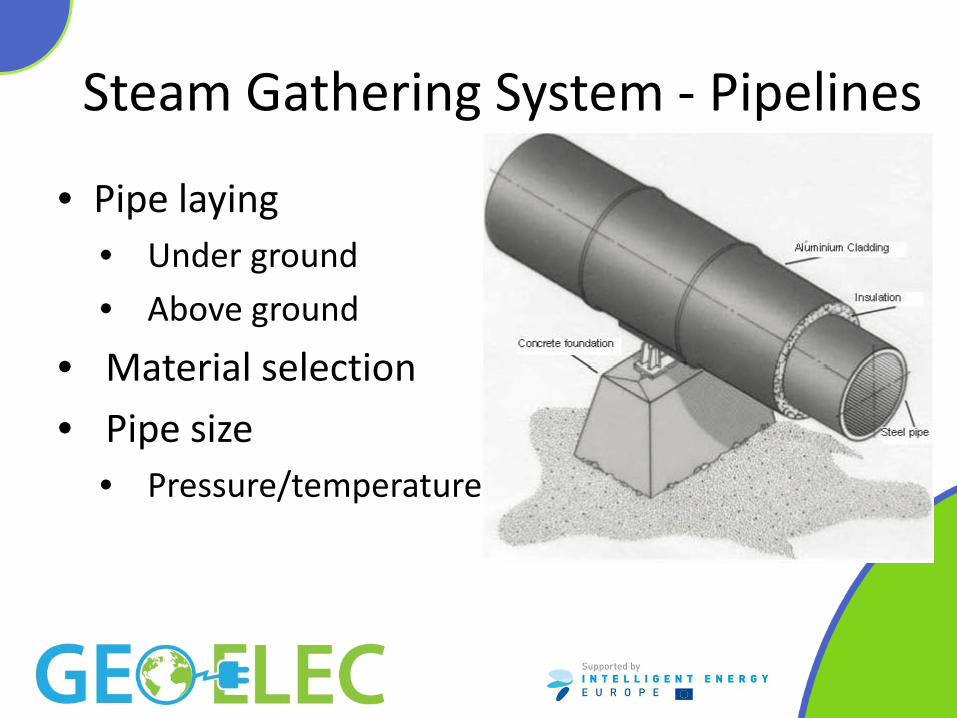
Steam Gathering System - Pipelines
• Pipe laying • Under ground
• Above ground
• Material selection
• Pipe size • Pressure/temperature

Steam Supply System – Pipelines
300
400
500
600
700
800
900
1000
0 20 40 60 80 100 120 140 160
Pipe
dia
met
er [m
m]
Flow [kg/s]
7 bar-a
20 bar-a

Steam gathering system – route selection
• Public safety
• Environmental impact
• Restriction on land
• Cost efficiency

Steam pipelines

Steam Supply - Layout
• Central separation station
• Satellite separation stations
• Individual separators
Central Satellite Individual
Source: Di Pippo

Power plant layout


Steam Supply - Separators
• Cyclone separators
• Gravity separators
• Efficiency • Steam separator and moisture separator
should together achieve 99,99 % bw. liquid removal or better

Calculated example
• The presenter will go through a calculated example to show methods used for basic engineering within steam gathering system design. The example taken will be connected to the special conditions encountered in geothermal energy.

Example • Example for1200 kJ/kg well enthalpy
– 40-50°C condensing temperature
– Back pressure
• Objective – Maximize the power production

• Assumptions – Assume that we know the reservoir enthalpy
– We know the condenser temperature
– Assume that separation pressure does not influence the well flow

Example, condensing unit
Condensing, 40°C
Condensing, 50°C

Example, condensing unit
• The maximum power will be 12,4 MW – Entalpy = 1200 kJ/kg
– Condesing pressure 0,075 bara / temperature 40°C
– Separation pressure 6 bara
– Flow 100 kg/s
• What if we selected backpressure instead?

Example, back pressure

Example, back pressure
• The maximum power will be 6,4 MW – Entalpy = 1200 kJ/kg
– Separation pressure 12 bara
– Flow 100 kg/s

Example
• Optimum separation pressure is 6 bara, is that ok?
• Saturation temperature for 1200 kJ/kg is 273°C
0
200
400
600
800
1000
1200
1400
1.00 10.00 100.00
SiO
2(m
g/kg
)
Pressure (bar-a)
quartz solubility (F&P82)
amorphous silica solubility (F77)
330 °C
300 °C
270 °C
240 °C

Bibliography • Di Pippo, Ronald: Geothermal Power Plants: Principles, Applications, Case
Studies and Environmental Impact, Elsevier Science, Dartmouth, Massachusetts, (2007).
• Technology Platform on Geothermal Electricity (TP-Geoelec) “Strategic Research Priorities for Geothermal Electricity» available on the Internet at: www.egec.org
• Technology Roadmap “Geothermal Heat and Power”, © OECD/IEA, 2011 International Energy Agency, www.iea.org • Bombarda, P., Invernizzi, C., Pietra C., “Heat recovery from Diesel engines:
A thermodynamic comparison between Kalina and ORC cycles” Applied Thermal Engineering 30 (2010) 212–219
• Di Pippo, R.: Second Law assessment of binary plants generating power from low-temperature geothermal fluids, Geothermics, 33, (2004), 565-586.

Thank You! VISIT GEOELEC.EU