process control valve engineering
TRANSCRIPT

© 2014 / CONFIDENTIAL
PROCESS CONTROL VALVE
ENGINEERING
ENG / ISLAM DEIF

© 2014 / CONFIDENTIAL
OUTLINE
Introduction to Control Valve Terminology
Control Valve Types
Actuators types
Valve Accessories
Phenomena Associated to the Control Valve
Valve Selection and Sizing
Testing and Installation

© 2014 / CONFIDENTIAL
INTRODUCTION
ISLAM DEIF 3

© 2014 / CONFIDENTIAL ISLAM DEIF 4
CONTROL VALVE TERMINOLOGY
CONTROL VALVE
A power actuated device which modifies the fluid flow rate in a process
control system. It consists of a valve connected to an actuator mechanism
(including all related accessories) that is capable of changing the position
of a closure member in the valve in response to a signal from the
controlling system.
Control valve is considered the most important final control element in a
process control loops

© 2014 / CONFIDENTIAL ISLAM DEIF 5
CONTROL VALVE TERMINOLOGY
BASIC CONTROL LOOP
There are 2 types of control loops
Open-Loop Control System
Closed-Loop Control System

© 2014 / CONFIDENTIAL ISLAM DEIF 6
CONTROL VALVE TERMINOLOGY
CONTROL VALVE GAIN
The change in the flow rate as a function of the change in valve travel. It
is the slope of the installed flow characteristic curve.

© 2014 / CONFIDENTIAL ISLAM DEIF 7
CONTROL VALVE TERMINOLOGY
HYSTERESIS
The maximum difference in output value for any single input value during
a calibration cycle, excluding errors due to dead band.

© 2014 / CONFIDENTIAL ISLAM DEIF 8
CONTROL VALVE TERMINOLOGY
DEAD BAND (BACKLASH)
The range through which an input signal can be varied, upon reversal of
direction, without initiating an observable change in the output signal.
Dead band is the name given to a general phenomenon that can apply to
any device. For the valve assembly, the controller output (CO) is the input
to the valve assembly and the process variable (PV) is the output of the
control valve .

© 2014 / CONFIDENTIAL ISLAM DEIF 9
CONTROL VALVE TERMINOLOGY
HYSTERESIS & DEAD BAND EFFECTS

© 2014 / CONFIDENTIAL ISLAM DEIF 10
CONTROL VALVE TERMINOLOGY
LINEARITY
The closeness to which a curve relating to two variables approximates a
straight line. (Linearity also means that the same straight line will apply for
both upscale and downscale directions. Thus, dead band as defined above,
would typically be considered a non-linearity)

© 2014 / CONFIDENTIAL ISLAM DEIF 11
CONTROL VALVE TERMINOLOGY
Rangeability
The ratio of the largest flow coefficient (Cv or Kv) to the smallest
controllable flow coefficient (Cv or Kv) within which the deviation from
the specified flow characteristic does not exceed the stated limits.
Turndown
Turndown applies to the application and is the ratio of the calculated Cv
at maximum conditions to the calculated Cv at minimum.

© 2014 / CONFIDENTIAL ISLAM DEIF 12
CONTROL VALVE TERMINOLOGY
ACCURACY
the degree of conformity of an indicated value to a recognized accepted
standard value or ideal value.
REPEATABILITY
The closeness of agreement among a number of consecutive
measurements of the output for the same value of input under the same
operating conditions, approaching from the same direction, for full range
traverses. It does not include hysteresis.

© 2014 / CONFIDENTIAL ISLAM DEIF 13
CONTROL VALVE TERMINOLOGY
LOOP GAIN:
The combined gain of all the components in the loop when viewed in
series around the loop Sometimes referred to as open-loop gain.
RESOLUTION:
The minimum possible change in input required to produce a detectable
change in the output when no reversal of the input takes place.
Resolution is typically expressed as a percent of the input span.
© 2014 / CONFIDENTIAL ISLAM DEIF 14
CONTROL VALVE TERMINOLOGY
Dead Time
The time interval (Td) in which no response of the system is detected
following a small (usually 0.25% - 5%) step input. It is measured from the
time the step input is initiated to the first detectable response of the
system being tested. Dead Time can apply to a valve assembly or to the
entire process
DRIFT
An undesired change in the output/input relationship over a period of
time.
CAPACITY (VALVE)
The rate of flow through a valve under stated conditions (CV).

© 2014 / CONFIDENTIAL ISLAM DEIF 15
CONTROL VALVE TERMINOLOGY
FRICTION
A force that tends to oppose the relative motion between two surfaces
that are in contact with each other. The friction force is a function of the
normal force holding these two surfaces together and the characteristic
nature of the two surfaces. Friction has two components: static friction
and dynamic friction. Static friction is the force that must be overcome
before there is any relative motion between the two surfaces. Once
relative movement has begun, dynamic friction is the force that must be
overcome to maintain the relative motion.
“Stiction” is terms that are sometimes used to describe static friction.

© 2014 / CONFIDENTIAL ISLAM DEIF 16
CONTROL VALVE TERMINOLOGY
Principles of valve throttling processes
A control valve modifies the fluid flow rate in a process pipeline by
providing a means to change the effective cross sectional area at the
valve.
This in turn forces the fluid to increase its velocity as passes through the
restriction. Even though it slows down again after leaving the valve, some
of the energy in the fluid is dissipated through flow separation effects and
frictional losses, leaving a reduced pressure in the fluid downstream of the
valve.
© 2014 / CONFIDENTIAL ISLAM DEIF 17
CONTROL VALVE TERMINOLOGY
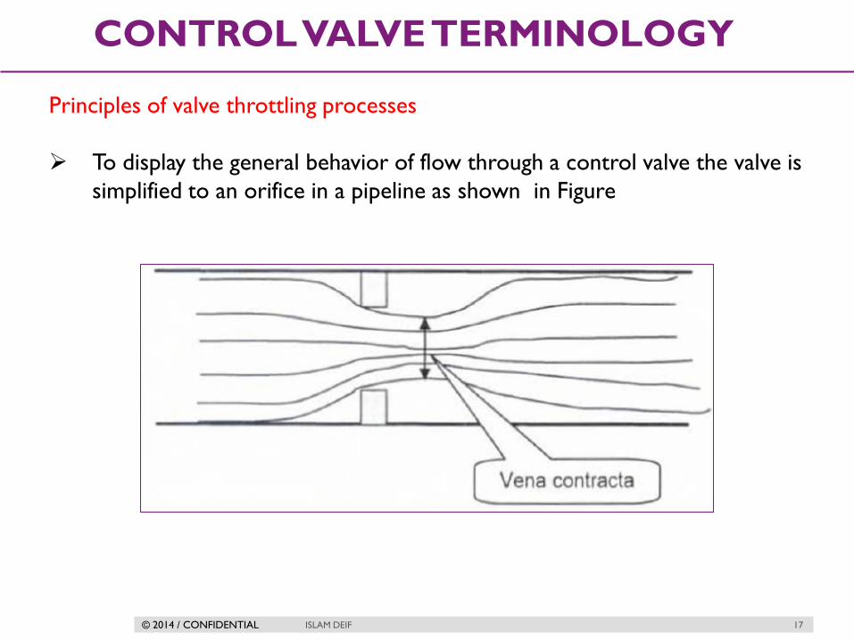
Principles of valve throttling processes
To display the general behavior of flow through a control valve the valve is
simplified to an orifice in a pipeline as shown in Figure

© 2014 / CONFIDENTIAL ISLAM DEIF 18
CONTROL VALVE TERMINOLOGY
Principles of valve throttling processes
it is important to understandhow the pressure conditions change In the
fluid as it passes through the restriction and the vena contracta and then
how the pressure partially recovers as the fluid enters the downstream
pipe area.
The first point to note is that the velocity of the fluid must increase as
the flow area decreases.
This is given by the continuity of flow equation;
V1.A1=V2.A2

© 2014 / CONFIDENTIAL ISLAM DEIF 19
CONTROL VALVE TERMINOLOGY
Principles of valve throttling processes
Now to consider the pressure conditions we apply Bernoulli's equation
,which demonstrates the balance between dynamic, hydrostatic pressure
and Static. Energy must be balanced each side of the flow restriction so
that:

© 2014 / CONFIDENTIAL ISLAM DEIF 20
CONTROL VALVE TERMINOLOGY
Principles of valve throttling processes

© 2014 / CONFIDENTIAL ISLAM DEIF 21
CONTROL VALVE STANDARDS
Control Valve Standards
Numerous standards are applicable to control valves. International and
global standards are becoming increasingly important for companies that
participate in global markets. Following is a list of codes and standards
that have been or will be important in the design and application of
control valves.
It covers the following issues
1-face to face dimensions.
2-Materials of construction.
3-Pressure-temperature ratings.
4-Design of some components to ensure adequate strength.
5-Testing procedures.

© 2014 / CONFIDENTIAL ISLAM DEIF 22
CONTROL VALVE STANDARDS
Well Known Valve Standards
ISA Instrument Society of America
ASME American Society of Mechanical Engineers
CEN European Committee for Standardization
API American Petroleum Institute
IEC International Electrotechnical Commission
ISO International Standards
Organization
ANSI American National Standards Institute

© 2014 / CONFIDENTIAL ISLAM DEIF 23
CONTROL VALVE STANDARDS
Instrument Society of America (ISA)
S51.1, Process Instrumentation Terminology
S75.01, Flow Equations for Sizing Control Valves
S75.02, Control Valve Capacity Test Procedures
S75.03, Face-to-Face Dimensions for Flanged Globe-Style Control Valve Bodies
(Classes 125, 150, 250, 300, and 600)
S75.04, Face-to-Face Dimensions for Flangeless Control Valves (Classes
150, 300, and 600)
S75.05, Terminology
S75.07, Laboratory Measurement of Aerodynamic Noise Generated by
Control Valves
S75.08, Installed Face-to-Face Dimensions for Flanged Clamp or Pinch Valves
S75.11, Inherent Flow Characteristic and Rangeability of Control Valves
S75.12, Face-to-Face Dimensions for Socket Weld-End and Screwed-End
Globe-Style Control Valves (Classes150, 300, 600, 900, 1500, and 2500)
S75.13, Method of Evaluating the Performance of Positioners with Analog
Input Signals

© 2014 / CONFIDENTIAL ISLAM DEIF 24
CONTROL VALVE STANDARDS
Instrument Society of America (ISA)
S75.14, Face-to-Face Dimensions for Buttweld-End Globe-Style Control
Valves (Class 4500)
S75.15, Face-to-Face Dimensions for Buttweld-End Globe-Style Control
Valves (Classes 150, 300, 600, 900, 1500, and 2500)
S75.16, Face-to-Face Dimensions for Flanged Globe-Style Control Valve
Bodies (Classes 900, 1500, and 2500)
S75.17, Control Valve Aerodynamic Noise Prediction
S75.19, Hydrostatic Testing of Control Valves
S75.20, Face-to-Face Dimensions for Separable Flanged Globe-Style Control
Valves (Classes 150, 300, and 600)
S75.22, Face-to-Centerline Dimensions for Flanged Globe-Style Angle Control
Valve Bodies (Classes 150, 300, and 600)
RP75.23, Considerations for Evaluating Control Valve Cavitation

© 2014 / CONFIDENTIAL ISLAM DEIF 25
CONTROL VALVE STANDARDS
ANSI -American National Standards Institute

© 2014 / CONFIDENTIAL ISLAM DEIF 26
CONTROL VALVE STANDARDS
API - American Petroleum Institute

© 2014 / CONFIDENTIAL ISLAM DEIF 27
CONTROL VALVE STANDARDS
ASME-American Society of Mechanical Engineers
NACE-National Association of Corrosion Engineers

© 2014 / CONFIDENTIAL
CONTROL VALVE
COMPONENTS
ISLAM DEIF 28

© 2014 / CONFIDENTIAL ISLAM DEIF 29
CONTROL VALVE COMPONENTS
Actuator
Body
Accessories

© 2014 / CONFIDENTIAL ISLAM DEIF 30
CONTROL VALVE COMPONENTS
Basic Valve Components
BODY
BONNET
TRIM
PACKING
ACTUATOR

© 2014 / CONFIDENTIAL ISLAM DEIF 31
CONTROL VALVE COMPONENTS
Body
Is the main part of the valve. All other parts fit onto the body.
It is usually cast or forged and the shape varies with the type of valve.
Inlet and outlet pipes fit onto the valve body through threaded, bolted
(flanged) or welded joints.
The fluid passes through the valve body when the valve is open.
The valve body must be strong enough to take the maximum pressure of
the process fluid. It must also be made of a material that is not attacked
by the fluid.
Bonnet
Is a removable cover fitted to the body. Some bonnets support the
moving parts of the valve. Others just close the hole in the body through
which the moving parts pass for assembly and dismantling.

© 2014 / CONFIDENTIAL ISLAM DEIF 32
CONTROL VALVE COMPONENTS
Trim (Plug and Seat )
Is the name given to the parts inside a valve. This normally includes:
The opening/closing element—closes the fluid path through the valve
body
The valve stem—connects the actuator to the closing element
The valve seat—makes a seal with the closing element when the valve is
closed
Packing
It allows the valve stem to pass into the valve body without loss of fluid
or fluid pressure from the valve. It forms a dynamic seal between the
valve stem and the bonnet.
Actuator
Operates the stem and closing element assembly.

© 2014 / CONFIDENTIAL ISLAM DEIF 33
CONTROL VALVE COMPONENTS
End Connections
Must be specified when buying the valve – butt weld end, compression flange,
pipe thread, quick disconnect

© 2014 / CONFIDENTIAL ISLAM DEIF 34
CONTROL VALVE COMPONENTS
End Connections

© 2014 / CONFIDENTIAL ISLAM DEIF 35
CONTROL VALVE COMPONENTS

© 2014 / CONFIDENTIAL ISLAM DEIF 36
CONTROL VALVE COMPONENTS
End Connecions

© 2014 / CONFIDENTIAL
CONTROL VALVE
BODY
ISLAM DEIF 37

© 2014 / CONFIDENTIAL ISLAM DEIF 38
CONTROL VALVE BODY
Control Valve Classification
Control Valve
Linear Motion
Globe
Globe
Single
port
Double port
Angle 3 way
Diaphragm Gate
Rotary Motion
Ball Butterfly Disk
© 2014 / CONFIDENTIAL ISLAM DEIF 39
CONTROL VALVE BODY
LINEAR (SLIDING STEM VALVES )
A sliding-stem valve body is one where the moving parts slide with a linear
motion.
Main types of linear valves :
Globe Valves
Diaphragm Valves
Gate Valves

© 2014 / CONFIDENTIAL ISLAM DEIF 40
CONTROL VALVE BODY
Globe Valves
Globe valves restrict the flow of fluid by altering the distance between a
movable plug and a stationary seat (in some cases, a pair of plugs and
matching seats). Fluid flows through a hole in the center of the seat, and is
more or less restricted by how close the plug is to that hole. The globe
valve design is one of the most popular sliding-stem valve designs used in
throttling service.

© 2014 / CONFIDENTIAL ISLAM DEIF 41
CONTROL VALVE BODY
SINGLE-PORTED GLOBE
Large amount of force required to drive the stem
Tight shut off
Used in small diameter applications

© 2014 / CONFIDENTIAL ISLAM DEIF 42
CONTROL VALVE BODY
DOUBLE-PORTED GLOBE VALVE
The purpose of a double-ported
globe valve is to minimize the force
applied to the stem by process fluid
pressure across the plugs which
comes in trade of tight shutoff of the
valve

© 2014 / CONFIDENTIAL ISLAM DEIF 43
CONTROL VALVE BODY
Application
Throttling general purpose flow control valve
Advantages Disadvantages
Faster than gate, seat less wear and
tear, high pressure drop for pressure
control.
Minimizes disassembly for
maintenance.
Streamlined flow path with a
minimum of parts and no irregular
cavities.
High pressure drop, require
considerable power to operate
(gears and levers), heavy.
Valves cannot be welded in-line
since the valve body is required to
be split.
© 2014 / CONFIDENTIAL ISLAM DEIF 44
CONTROL VALVE BODY
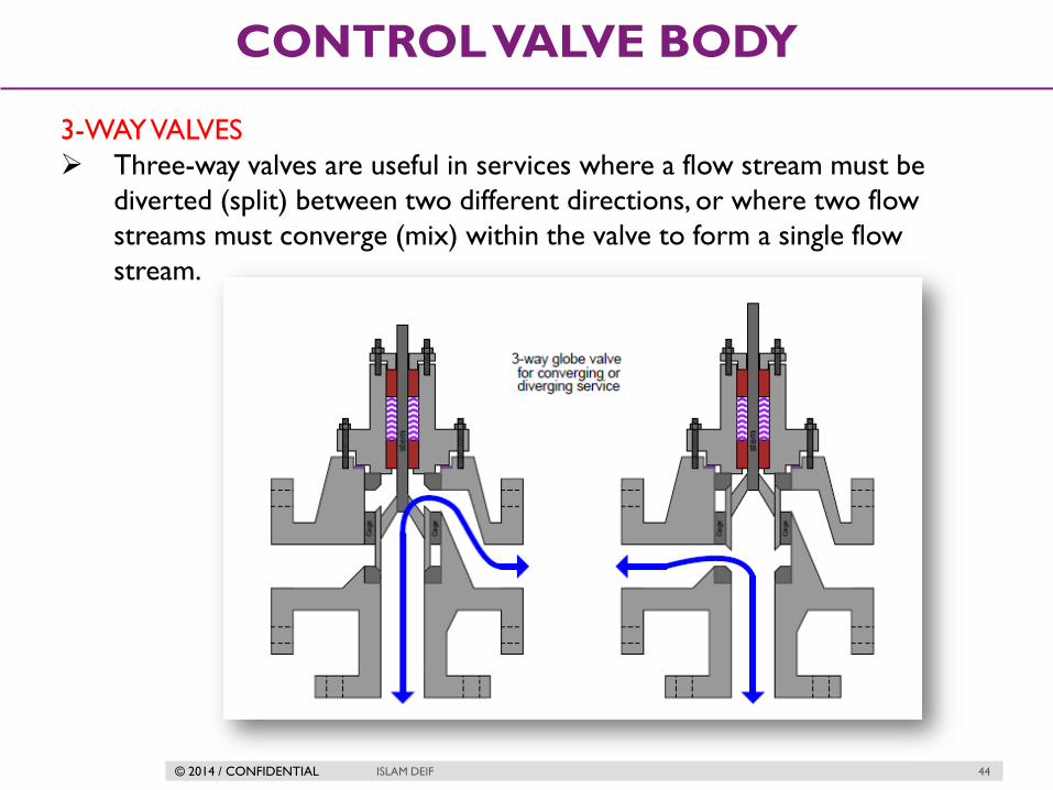
3-WAY VALVES
Three-way valves are useful in services where a flow stream must be
diverted (split) between two different directions, or where two flow
streams must converge (mix) within the valve to form a single flow
stream.

© 2014 / CONFIDENTIAL ISLAM DEIF 45
CONTROL VALVE BODY
ANGLE VALVES
The inlet and outlet ports are at
right angle to each other .
Can be installed in case of no
inline globe valve can be installed

© 2014 / CONFIDENTIAL ISLAM DEIF 46
CONTROL VALVE BODY
Z GLOBE VALVE
The name is given because of the path the fluid has to take as it passes
through the valve. It changes direction twice, like the letter Z.
Z-type globe valves are used mainly for small-size, low-pressure
applications. In large, high-pressure lines, the changes of flow direction
cause a large pressure drop and turbulence that can damage the trim.

© 2014 / CONFIDENTIAL ISLAM DEIF 47
CONTROL VALVE BODY
Y GLOBE VALVE
Having the seat at about 45 to the flow direction straightens the flow
path and reduces the pressure drop. This type of valve can be used for
high-pressure applications.
Have the property of self drain useful in high temperature application

© 2014 / CONFIDENTIAL ISLAM DEIF 48
CONTROL VALVE BODY
DIAPHRAGM VALVE
Diaphragm valves use a flexible sheet
pressed close to the edge of a solid dam
to narrow the flow path for fluid. These
valves are well suited for flows
containing solid particulate matter such
as slurries.
Precise throttling may be difficult to
achieve due to the elasticity of the
diaphragm.
This diaphragm completely separates
the valve trim from the fluid flowing
through the valve. This means that the
fluid does not contact the trim and the
stem does not need any gland packing.

© 2014 / CONFIDENTIAL ISLAM DEIF 49
CONTROL VALVE BODY
DIAPHRAGM VALVE ASSEMBLY

© 2014 / CONFIDENTIAL ISLAM DEIF 50
CONTROL VALVE BODY
Diaphragm Valve positions (on-off)

© 2014 / CONFIDENTIAL ISLAM DEIF 51
CONTROL VALVE BODY
DIAPHRAGM VALVE POSITIONS (THROTTLING)

© 2014 / CONFIDENTIAL ISLAM DEIF 52
CONTROL VALVE BODY
Application
Used for biochemical processes. used for regulation of most gases and
liquids
Advantages Disadvantages
Valve components can be isolated
from the process fluid.
Valve construction prevents leakage
ofthe fluid without the
use of a gland seal (packing)
The diaphragm becomes worn
more easily and regular
maintenance is necessary.
These types of valves are generally
not suited for very high
temperature fluids and are mainly
used on liquid systems.

© 2014 / CONFIDENTIAL ISLAM DEIF 53
CONTROL VALVE BODY
GATE VALVE
Gate valves work by inserting a dam (gate) into
the path of the flow to restrict it, in a manner
similar to the action of a sliding door. Gate
valves are more often used for on/off control
than for throttling.

© 2014 / CONFIDENTIAL ISLAM DEIF 54
CONTROL VALVE BODY
Rising and Non Rising stem

© 2014 / CONFIDENTIAL ISLAM DEIF 55
CONTROL VALVE BODY
GATE VALVE WITH HANDWHEEL
Turning the hand wheel raises and lowers the gate.
When the gate valve is fully closed, the gate fills the passage and stops the
flow through the valve completely.
When the valve is fully opened, the gate is positioned above the passage
in the valve body. This allows full flow through the valve, with little or no
obstruction. There is very little pressure drop across the valve.
© 2014 / CONFIDENTIAL ISLAM DEIF 56
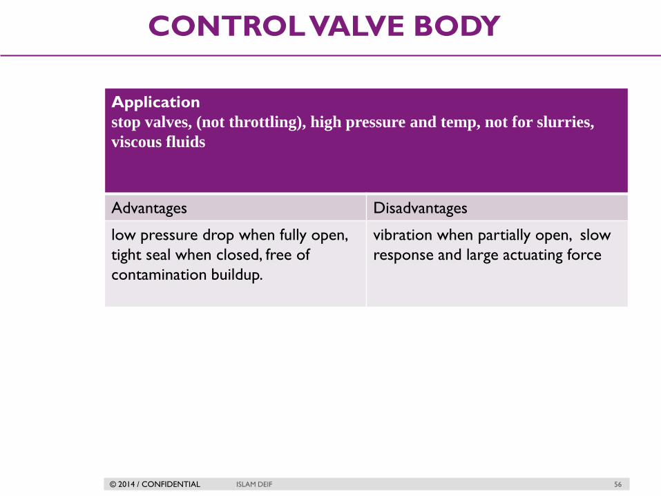
CONTROL VALVE BODY
Application
stop valves, (not throttling), high pressure and temp, not for slurries,
viscous fluids
Advantages Disadvantages
low pressure drop when fully open,
tight seal when closed, free of
contamination buildup.
vibration when partially open, slow
response and large actuating force

© 2014 / CONFIDENTIAL ISLAM DEIF 57
CONTROL VALVE BODY
Knife Gate valve
Knife gate valves, have a simple, one-piece closing element. It is a parallel-
sided plate that may move clear of the flow path to open or may have a
hole that moves into the flow path.

© 2014 / CONFIDENTIAL ISLAM DEIF 58
CONTROL VALVE BODY
ROTARY VALVES
A different strategy for controlling the flow of fluid is to insert a rotary
element into the flow path. Instead of sliding a stem into and out of the
valve body to actuate a throttling mechanism, rotary valves rely on the
rotation of a shaft to actuate the trim. An important advantage of rotary
control valves over sliding-stem designs such as the globe valve and
diaphragm valve is a virtually obstruction less path for fluid when the
valve is wide-open.
MAIN TYPES OF ROTARY VALVES
Ball Valves
Butterfly Valves
Disc Valves

© 2014 / CONFIDENTIAL ISLAM DEIF 59
CONTROL VALVE BODY
BALL VALVE
In the ball valve design, a spherical ball with a passageway cut through the
center rotates to allow fluid more or less access to the passageway. When
the passageway is parallel to the direction of fluid motion, the valve is
wide open; when the passageway is aligned perpendicular to the direction
of fluid motion, the valve is fully shut (closed).

© 2014 / CONFIDENTIAL ISLAM DEIF 60
CONTROL VALVE BODY
BALL VALVES OPEN / CLOSE STATES
CLOSE OPEN

© 2014 / CONFIDENTIAL ISLAM DEIF 61
CONTROL VALVE BODY
Application
Flow control, pressure control, shutoff, corrosive fluids, liquids gases,
high temp.
Advantages Disadvantages
Low pressure drop, low leakage,
small, rapid opening.
Low cost and weight relative to
globes as size increases
High flow capacities (2 to 3 times
that of globe valves)
Tight shutoff
Low stem leakage
Easily fitted with quarter turn
actuators
Seat can wear if used for throttling,
quick open may cause hammer.
Over sizing.
High cost in large sizes compared to
butterfly valves.

© 2014 / CONFIDENTIAL ISLAM DEIF 62
CONTROL VALVE BODY
BUTTERFLY VALVES
Butterfly valves are quite simple to understand:
the “butterfly” element is a disk that rotates
perpendicular to the path of fluid flow. When
parallel to the axis of flow, the disk presents
minimal obstruction; when perpendicular to the
axis, the disk completely blocks any flow. Fluid-tight
shutoff is difficult to obtain in the classic butterfly
design unless the seating area is lined with a soft
(elastic) material.
The disc turns to open and close the valve. The disc or seat may be made of
a polymer (plastic) to give a better seal.
Butterfly valves are simple and take up little space. This makes them
especially good for use in large pipelines or where there is not much space.
Operating a butterfly valve can take a lot of force as you have to push it against
the fluid pressure. Larger valves usually have geared actuators to make
operation easier.

© 2014 / CONFIDENTIAL ISLAM DEIF 63
CONTROL VALVE BODY
BUTTERFLY POSITIONS

© 2014 / CONFIDENTIAL ISLAM DEIF 64
CONTROL VALVE BODY
BUTTERFLY POSITIONS
Most butterfly discs turn on a stem that passes through the center of the
disc along a diameter. When the valve is closed, fluid pressure pushes
equally on both sides of the stem: half the force is pushing in the closing
direction and half in the opening direction

© 2014 / CONFIDENTIAL ISLAM DEIF 65
CONTROL VALVE BODY
Application
Low pressure, large diameter lines where leakage is unimportant
Advantages Disadvantages
Low pressure drop, small and
lightweight.
Low cost and weight relative to
globes as size increases
High flow capacities
Low stem leakage
High leakage, high actuation forces
so limited to low pressures.
Over sizing

© 2014 / CONFIDENTIAL ISLAM DEIF 66
CONTROL VALVE BODY
DISC VALVE
Disk valves (often referred to as eccentric disk valves, or as high-
performance butterfly valves) are a variation on the butterfly design
intended to improve seat shut-off. The disk’s center is offset from the
shaft centerline, causing it to approach the seat with a “cam” action that
results in high seating pressure. Thus, tight shut-off of flow is possible even
when using metal seats and disks.

© 2014 / CONFIDENTIAL
SPECIAL VALVES
ISLAM DEIF 67

© 2014 / CONFIDENTIAL ISLAM DEIF 68
SPECIAL VALVES
Pressure relief valves
Pressure relief valves are used mainly to
relieve overpressure of liquids. This often
happens when a liquid in a closed container
or pipeline expands as its temperature
increases.
Under normal operating conditions, a spring
holds the PRV closed. Fluid pressure pushes
against the spring to open the valve. The
fluid pressure needed to push the valve
open is called the set point pressure. The
set point pressure is usually the maximum
normal operating pressure of the liquid.

© 2014 / CONFIDENTIAL ISLAM DEIF 69
SPECIAL VALVES
Pressure relief valves
An adjustment screw changes the spring force for different set point
pressures. When the liquid pressure exceeds the set point pressure, the
valve opens slowly. It releases just enough liquid to bring the pressure
down to the normal operating pressure. The spring then closes the valve
slowly so that normal operations can continue.

© 2014 / CONFIDENTIAL ISLAM DEIF 70
SPECIAL VALVES
Pressure safety valves
Pressure safety valves are used mainly to
relieve overpressure of gases and vapors
(e.g. steam). The set point pressure is
greater than the maximum normal
operating pressure of the process fluid but
less than the maximum safe working
pressure of the equipment.
When the fluid pressure exceeds the set
point pressure, the valve pops fully open.
This happens very quickly to release
overpressure as quickly as possible. The
pressure at which the valve closes again is
lower than the opening set point pressure.
The difference between opening and closing
pressures is called the blow down.

© 2014 / CONFIDENTIAL ISLAM DEIF 71
SPECIAL VALVES
Pressure safety valves
Blow down is given as a percentage of opening setpoint pressure.
EXAMPLE a valve may open at 15bar with a blowdown of 10%.
10% of 15bar is 1.5bar
the valve will close at a pressure that is 1.5bar lower than 15bar
15bar – 1.5bar = 13.5bar.
PSVs on gas processing systems normally vent to flare—the valve outlet
is connected to the flare system where the gas burns off.
PSVs on steam systems vent to atmosphere—the steam is released into
the air.

© 2014 / CONFIDENTIAL ISLAM DEIF 72
SPECIAL VALVES
Needle Valves
Needle valves are linear-motion valves. They can make very small
adjustments to flow rate. Their name comes from the long, tapered shape
of the bottom of the spindle that forms the closing element.

© 2014 / CONFIDENTIAL ISLAM DEIF 73
SPECIAL VALVES
Needle valve Positions

© 2014 / CONFIDENTIAL ISLAM DEIF 74
SPECIAL VALVES
Check Valves
Non-return valves, also called check valves, stop flow reversal in a pipe.
They only allow fluid to flow in one direction.
The pressure of the fluid passing through the valve in the correct
direction opens it automatically. If the flow tries to reverse, the valve
closes automatically. They have an arrow on the body that shows the
correct flow direction,. Make sure that you mount non-return valves the
correct way round.
© 2014 / CONFIDENTIAL ISLAM DEIF 75
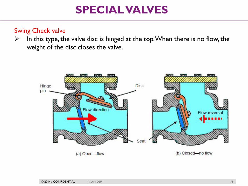
SPECIAL VALVES
Swing Check valve
In this type, the valve disc is hinged at the top. When there is no flow, the
weight of the disc closes the valve.

© 2014 / CONFIDENTIAL ISLAM DEIF 76
SPECIAL VALVES
Lift Check Valves
These valves have a similar valve body and seating arrangement to globe
valves.
Flow must enter from under the seat to lift the closing element. Flow in
the reverse direction pushes the closing element against its seat.

© 2014 / CONFIDENTIAL ISLAM DEIF 77
SPECIAL VALVES
Piston Check Valves
Piston check valves are similar to lift check valves. Instead of a valve disc
there is a piston that slides in a cylinder. This gives a smoother motion
during operation.

© 2014 / CONFIDENTIAL ISLAM DEIF 78
SPECIAL VALVES
Ball Check Valves
These have a spherical (ball-shaped) closing element. Like the other check
valves, the closing element may operate by gravity or the flow pressure or
it may be spring loaded.

© 2014 / CONFIDENTIAL
CONTROL VALVE
BODY SELECTION
ISLAM DEIF 79

© 2014 / CONFIDENTIAL ISLAM DEIF 80
CONTROL VALVE BODY SELECTION
Globe (Plug and Seat)
These are the most traditionally used control valves - generally available
from 12 to 400mm in all castable materials. Larger sizes are available but
it becomes more common to move to an angle construction on these
sizes.
Pressure ratings up to ANSI 2500# and higher are available.
The globe valve is very versatile offering reduced trim options as well as a
variety of special trims for severe high pressure drop applications. This
style of valve is easily adapted for use on cryogenic temperatures, and for
high temperature duties.
Turndown capability of 50:1 is available.

© 2014 / CONFIDENTIAL ISLAM DEIF 81
CONTROL VALVE BODY SELECTION
Butterfly
The least expensive of all control valves. Sizes range from 50 to 3000mm.
Pressure ratings are generally up to 1600 kpa(G).
Temperatures are up to 100C. This valve is good for corrosive
applications but does not handle high pressure drops well. It is the lightest
valve available - size for size. Turndown is 75:1.

© 2014 / CONFIDENTIAL ISLAM DEIF 82
CONTROL VALVE BODY SELECTION
Diaphragm / Pinch
These valves are inexpensive and very simple in operation. They are used
extensively in the mining industry for control of slurries and water.
The characteristic is basically quick opening and so these valves do not
give precise control or high turndown but function particularly well on
level control. Very good for low pressure abrasive applications.
Sizes are available from 25 to 350mm in pressure ratings up to 1000kPa
on the smaller sizes and 350kPa above 200mm. Special pinch valves can
handle pressures up to 100 bar.
Temperature limitation is about 100C. Turndown is 10:1.
© 2014 / CONFIDENTIAL ISLAM DEIF 83
CONTROL VALVE BODY SELECTION
Ball
Ball valves naturally have a good control characteristic and give high
turndown of 100:1 for standard ball valves and up to 500:1 for vee ported
valves.
High pressure valves are available to ANSI 2500# and higher - most valves
working at greater than 3000kPa have trunnion mounted balls.
Sizes range from 10mm to 500mm.
High temperatures are handled by valves with metal seats.
Full ball valves are not recommended for slurries due to the solids
settling out in the body cavity.
High pressure drops are not handled well due to the ball causing high
velocity jets of fluid directed into the seat and body - resulting in erosion.
This design of valve is particularly suitable for use with ceramic materials
and can be used on abrasive throttling duties where the pressures and
temperatures are too high for pinch or diaphragm valves.

© 2014 / CONFIDENTIAL ISLAM DEIF 84
CONTROL VALVE BODY SELECTION

© 2014 / CONFIDENTIAL
PACKING
ISLAM DEIF 85
© 2014 / CONFIDENTIAL ISLAM DEIF 86
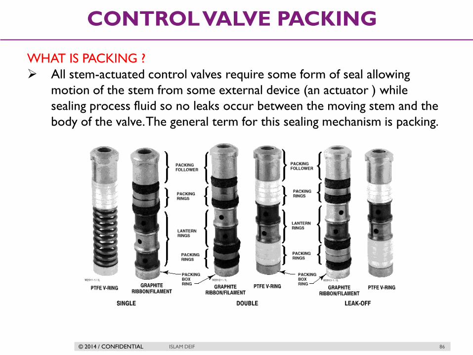
CONTROL VALVE PACKING
WHAT IS PACKING ?
All stem-actuated control valves require some form of seal allowing
motion of the stem from some external device (an actuator ) while
sealing process fluid so no leaks occur between the moving stem and the
body of the valve. The general term for this sealing mechanism is packing.

© 2014 / CONFIDENTIAL ISLAM DEIF 87
CONTROL VALVE PACKING
PACKING IN SLIDING STEM VALVE
The packing material takes the
form of several concentric rings,
stacked on the valve stem like
washers on a bolt. These packing
rings are forced down from
above by the packing flange to
apply a compressive force
around the circumference of the
valve stem. This compressive
force is necessary to generate
mechanical stress in the packing
material to make it seal tightly
against the stem of the valve and
the interior wall of the bonnet.
© 2014 / CONFIDENTIAL ISLAM DEIF 88
CONTROL VALVE PACKING
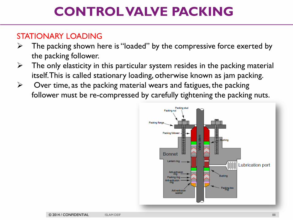
STATIONARY LOADING
The packing shown here is “loaded” by the compressive force exerted by
the packing follower.
The only elasticity in this particular system resides in the packing material
itself. This is called stationary loading, otherwise known as jam packing.
Over time, as the packing material wears and fatigues, the packing
follower must be re-compressed by carefully tightening the packing nuts.

© 2014 / CONFIDENTIAL ISLAM DEIF 89
CONTROL VALVE PACKING
LIVE-LOADED VALVE STEM PACKING
An alternative to “stationary” loading is to insert a metal spring into the
packing assembly, so that the elasticity of the spring helps to maintain an
appropriate amount of packing stress as the packing material wears and
ages. This is called live loading
© 2014 / CONFIDENTIAL ISLAM DEIF 90
CONTROL VALVE PACKING
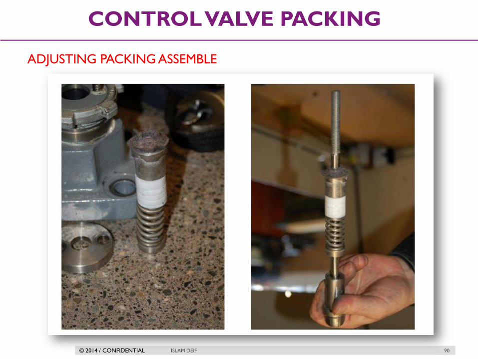
ADJUSTING PACKING ASSEMBLE
© 2014 / CONFIDENTIAL ISLAM DEIF 91
CONTROL VALVE PACKING
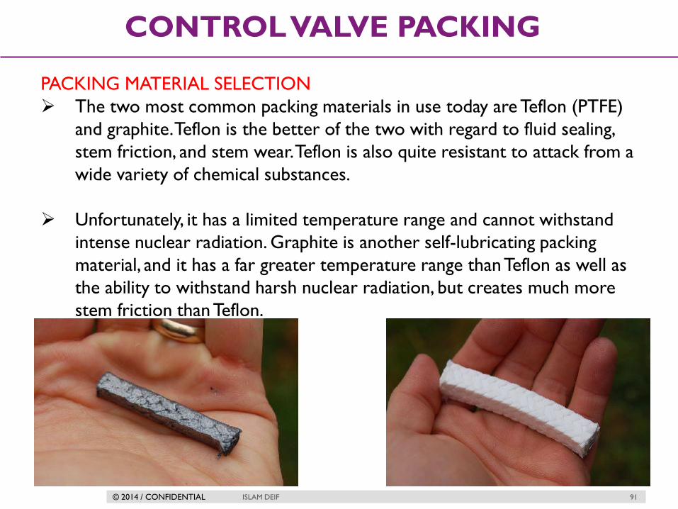
PACKING MATERIAL SELECTION
The two most common packing materials in use today are Teflon (PTFE)
and graphite. Teflon is the better of the two with regard to fluid sealing,
stem friction, and stem wear. Teflon is also quite resistant to attack from a
wide variety of chemical substances.
Unfortunately, it has a limited temperature range and cannot withstand
intense nuclear radiation. Graphite is another self-lubricating packing
material, and it has a far greater temperature range than Teflon as well as
the ability to withstand harsh nuclear radiation, but creates much more
stem friction than Teflon.

© 2014 / CONFIDENTIAL ISLAM DEIF 92
CONTROL VALVE PACKING
PACKING MATERIAL SELECTION
Graphite packing also has the unfortunate property of permitting galvanic
corrosion between the stem and bonnet metals due to its electrical
conductivity. Sacrificial zinc washers are sometimes added to graphic
packing assemblies to help mitigate this corrosion, but this only
postpones rather than prevents corrosive damage to the stem.
Hybrid packing materials, such as carbon-reinforced Teflon, also exist in an
attempt to combine the best characteristics of both technologies.

© 2014 / CONFIDENTIAL ISLAM DEIF 93
CONTROL VALVE PACKING
Typical Packing friction values

© 2014 / CONFIDENTIAL ISLAM DEIF 94
CONTROL VALVE PACKING
PACKING MATERIAL SPECIFICATION
Temp.
RangeCommon use
Suitablity
for Oxygen
/Oxidizing
Service
Packing material DescriptionStem
friction
Special
consideration
-73 to 232C Non-Radioactive YesPTFE impregented
composition
Split rings of braided
composition impregented with
PTFE
Low -
All chemicals ( Except
Molten alkali) Non
radioactive
No single PTFE V - Ring Solid rings of molded PTFE Low
Vacuum Pressure /
VacuumNo Double PTFE V - Ring Solid rings of molded PTFE Low
-84 to 232CVacuum, All chemicals
( Except molten alkali )Yes Chesterton 324
Split rings of braided,
preshrunk PTFE yarn
impregented with PTFE;
available with copper rings at
top and bottom of packing
box to meet UOP
specification 6-14-0 for acid
service.
Low -
-18 to 538C
Water, Stem Petroleum
products, Radiactive
and Non-radiactive
nuclear
Yes but upto
371C
Graphite/
Ribbon/Filament
Ribbon style graphite rings
and rings of braided graphite
fibers with sacrificial zinc
washer
High
Low chloride
content ( less then
100ppm) chrome
plated stem not
necessary for high
temperature service
371 to 649CHigh temperature
oxidizing serviceYes
Ribbon - Style
graphite
Solid rings of ribbon-style
graphite with sacrificial zinc
washers
High -
-40 to 232C
Required 2 to 4
micro inch RMS
valve plug stem
finish

© 2014 / CONFIDENTIAL
SHUTOFF CLASSES
ISLAM DEIF 95

© 2014 / CONFIDENTIAL ISLAM DEIF 96
SHUTOFF CLASSES
VALVE SEAT LEAKAGE
In some process applications, it is important that the control valve be able
to completely stop fluid flow when placed in the “closed” position.
Many control valves spend most of their operating lives in a partially-open
state, rarely opening or closing fully. Additionally, some control valve
designs are notorious for the inability to completely shut off (e.g. double-
ported globe valves).
Given the common installation of manual “block” valves upstream and
downstream of a control valve, there is usually a way to secure zero flow
through a pipe even if a control valve is incapable of tight shut-off. For
some applications, however, tight control valve shut-off is a mandatory
requirement.
A control valve's ability to shut off has to do with many factors as the
type of valves for instance. A double seated control valve have very poor
shut off capability. The guiding, seat material, actuator thrust, pressure
drop, and the type of fluid can all play a part in how well a particular
control valve shuts off.

© 2014 / CONFIDENTIAL ISLAM DEIF 97
SHUTOFF CLASSES
VALVE LEAKAGE CLASSIFICATIONS
Class I - Valve Leakage Classifications
Identical to Class II, III, and IV in construction and design intent, but no actual
shop test is made. Class I is also known as dust tight and can refer to
metal or resilient seated valves.

© 2014 / CONFIDENTIAL ISLAM DEIF 98
SHUTOFF CLASSES
VALVE LEAKAGE CLASSIFICATIONS
Class II - Valve Leakage Classifications
Intended for double port or balanced singe port valves with a metal piston
ring seal and metal to metal seats.
0.5% leakage of full open valve capacity.
Service dP or 50 psid (3.4 bar differential), whichever is lower at 50 to 125 F.
Test medium air at 45 to 60 psig is the test fluid.
Typical constructions:
Balanced, single port, single graphite piston ring, metal seat, low seat load
Balanced, double port, metal seats, high seat load

© 2014 / CONFIDENTIAL ISLAM DEIF 99
SHUTOFF CLASSES
VALVE LEAKAGE CLASSIFICATIONS
Class III - Valve Leakage Classifications
Intended for the same types of valves as in Class II.
0.1% leakage of full open valve capacity.
Service dP or 50 psid (3.4 bar differential), whichever is lower at 50 to 125 oF.
Test medium air at 45 to 60 psig is the test fluid.
Typical constructions:
Balanced, double port, soft seats, low seat load
Balanced, single port, single graphite piston ring, lapped metal seats,
medium seat load

© 2014 / CONFIDENTIAL ISLAM DEIF 100
SHUTOFF CLASSES
VALVE LEAKAGE CLASSIFICATIONS
Class IV - Valve Leakage Classifications
Intended for single port and balanced single port valves with extra tight piston
seals and metal to-metal seats.
0.01% leakage of full open valve capacity.
Service dP or 50 psid (3.4 bar differential), whichever is lower at 50 to 125 oF.
Test medium air at 45 to 60 psig is the test fluid.
Typical constructions:
Balanced, single port, Teflon piston ring, lapped metal seats, medium seat
load
Balanced, single port, multiple graphite piston rings, lapped metal seats
Unbalanced, single port, lapped metal seats, medium seat load
Class IV is also known as metal to metal

© 2014 / CONFIDENTIAL ISLAM DEIF 101
SHUTOFF CLASSES
VALVE LEAKAGE CLASSIFICATIONS
Class V - Valve Leakage Classifications
Intended for the same types of valves as Class IV.
The test fluid is water at 100 psig or operating pressure.
Leakage allowed is limited to 5 x 10 ml per minute per inch of orifice
diameter per psi differential.
Service dP at 50 to 125 oF.
Typical constructions:
Unbalanced, single port, lapped metal seats, high seat load
Balanced, single port, Teflon piston rings, soft seats, low seat load
Unbalanced, single port, soft metal seats, high seat load

© 2014 / CONFIDENTIAL ISLAM DEIF 102
SHUTOFF CLASSES
VALVE LEAKAGE CLASSIFICATIONS
Class VI - Valve Leakage Classifications
Class Vl is known as a soft seat classification. Soft Seat Valves are those
where the seat or shut-off disc or both are made from some kind of
resilient material such as Teflon. Intended for resilient seating valves.
The test fluid is air or nitrogen.
Pressure is the lesser of 50 psig or operating pressure.
The leakage limit depends on valve size and ranges from 0.15 to 6.75 ml
per minute for valve sizes 1 through 8 inches.
Typical constructions:
Unbalanced, single port, soft seats, low load

© 2014 / CONFIDENTIAL ISLAM DEIF 103
SHUTOFF CLASSES
VALVE LEAKAGE CLASSIFICATIONS
Class VI - Valve Leakage Classifications
Port Diameter Bubbles per
minute
ml per
minute inches Millimeters
1 25 1 0.15
1 1/2 38 2 0.30
2 51 3 0.45
2 1/2 64 4 0.60
3 76 6 0.90
4 102 11 1.70
6 152 27 4.00
8 203 45 6.75
10 254 63 9
12 305 81 11.5

© 2014 / CONFIDENTIAL ISLAM DEIF 104
SHUTOFF CLASSES
VALVE LEAKAGE CLASSIFICATIONS
Class VI - Valve Leakage Classifications
The “bubble test” used for Class VI
seat leakage is based on the leakage
rate of air or nitrogen gas past the
closed valve seat as measured by
counting the rate of gas bubbles
escaping a bubble tube submerged
under water.
It is from this leakage test procedure that the term bubble-tight shut-of
originates.

© 2014 / CONFIDENTIAL ISLAM DEIF 105
SHUTOFF CLASSES
Control Valve Leakage Classification - Overview
Leakage Class
Designation
Maximum Leakage
Allowable Test Medium Test Pressure
Testing Procedures
Required for
Establishing Rating
I x x x No test required
II 0.5% of rated
capacity
Air or water at 50 -
125o F
(10 - 52oC)
45 - 60 psig or
maximum operating
differential whichever
is lower
45 - 60 psig or
maximum operating
differential whichever
is lower
III 0.1% of rated
capacity As above As above As above
IV 0.01% of rated
capacity As above As above As above
V
0.0005 ml per minute
of water per inch of
port diameter per psi
differential
Water at 50 to125oF
(10 to 52oC)
Maximum service
pressure drop across
valve plug not to
exceed ANSI body
rating
Maximum service
pressure drop across
valve plug not to
exceed ANSI body
rating
VI
Not to exceed
amounts shown in
the table above
Air or nitrogen at 50
to 125o F (10 to
52oC)
50 psig or max rated
differential pressure
across valve plug
whichever is lower
Actuator should be
adjusted to operating
conditions specified
with full normal
closing thrust applied
to valve plug seat

© 2014 / CONFIDENTIAL
CONTROL VALVE
ACTUATORS
ISLAM DEIF 106

© 2014 / CONFIDENTIAL ISLAM DEIF 107
CONTROL VALVE ACTUATORS
ACTUATORS
These are the main types of actuator:
Manual
Pneumatic
Electric motor
Hydraulic
Self-actuated

© 2014 / CONFIDENTIAL ISLAM DEIF 108
CONTROL VALVE ACTUATORS
PNEUMATIC ACTUATORS
They are basically of two types
1. Diaphragm actuator
2. Piston actuator
These actuators are designed so that with a specific change of air pressure,
the spindle will move sufficiently to move the valve through its complete
stroke from fully-closed to fully-open.

© 2014 / CONFIDENTIAL ISLAM DEIF 109
CONTROL VALVE ACTUATORS
DIAPHRAGM ACTUATORS
They have compressed air applied to a flexible membrane called the
diaphragm.
They are single acting i.e. air is supplied from single side of the diaphragm.
© 2014 / CONFIDENTIAL ISLAM DEIF 110
CONTROL VALVE ACTUATORS
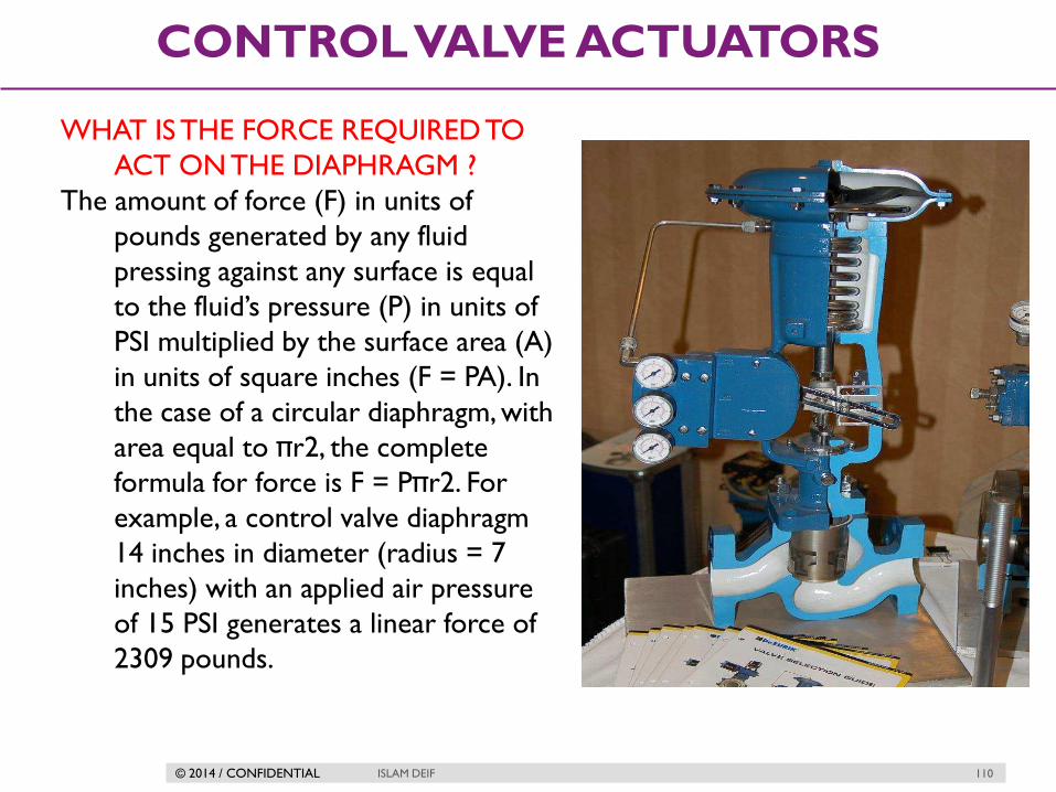
WHAT IS THE FORCE REQUIRED TO
ACT ON THE DIAPHRAGM ?
The amount of force (F) in units of
pounds generated by any fluid
pressing against any surface is equal
to the fluid’s pressure (P) in units of
PSI multiplied by the surface area (A)
in units of square inches (F = PA). In
the case of a circular diaphragm, with
area equal to πr2, the complete
formula for force is F = Pπr2. For
example, a control valve diaphragm
14 inches in diameter (radius = 7
inches) with an applied air pressure
of 15 PSI generates a linear force of
2309 pounds.

© 2014 / CONFIDENTIAL ISLAM DEIF 111
CONTROL VALVE ACTUATORS
DIAPHRAGM ACTUATORS ASSEMBLY
© 2014 / CONFIDENTIAL ISLAM DEIF 112
CONTROL VALVE ACTUATORS
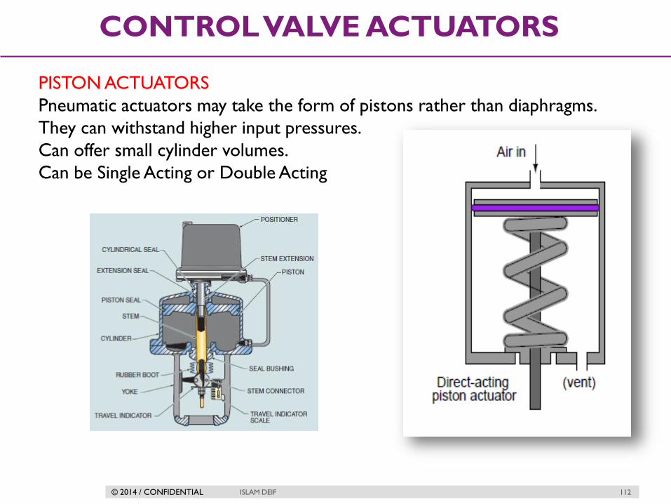
PISTON ACTUATORS
Pneumatic actuators may take the form of pistons rather than diaphragms.
They can withstand higher input pressures.
Can offer small cylinder volumes.
Can be Single Acting or Double Acting

© 2014 / CONFIDENTIAL ISLAM DEIF 113
CONTROL VALVE ACTUATORS
HOW CAN MORE PRESSURE ENHANCE FORCE GENERATED ?!
Piston actuators generally have longer stroke lengths than diaphragm
actuators, and are able to operate on much greater air pressures. Since
actuator force is a function of fluid pressure and actuator area (F = PA),
this means piston actuators are able to generate more force than
diaphragm actuators of the same diameter. A 14 inch diaphragm operating
at a maximum pressure of 35 PSI generates 5388 pounds of force, but the
same size piston operating at a maximum pressure of 150 PSI generates
23091 pounds of force.

© 2014 / CONFIDENTIAL ISLAM DEIF 114
CONTROL VALVE ACTUATORS
WHY PISTON ACTUATORS CAN BEAR MORE PRESSURE ?!
The greater pressure rating of a piston actuator comes from the fact that the
only “soft” component (the sealing ring) has far less surface area exposed
to the high pressure than a rolling diaphragm. This results in significantly
less stress on the elastic ring than there would be on an elastic diaphragm
exposed to the same pressure. There really is no limit to the stroke
length of a piston actuator as there is with the stroke length of a
diaphragm actuator. It is possible to build a piston actuator miles long, but
such a feat would be impossible for a diaphragm actuator, where the
diaphragm must stretch (or roll) the entire stroke length.
© 2014 / CONFIDENTIAL ISLAM DEIF 115
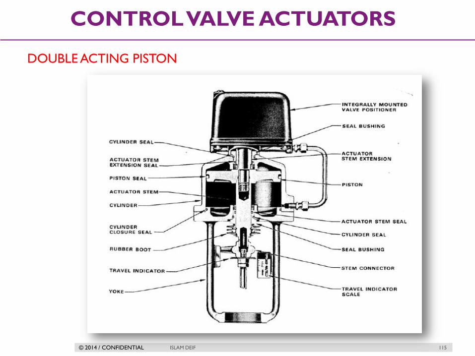
CONTROL VALVE ACTUATORS
DOUBLE ACTING PISTON

© 2014 / CONFIDENTIAL ISLAM DEIF 116
CONTROL VALVE ACTUATORS
Rotating Actuators (RACK-AND PINION
MECHANISM)
A pair of pneumatically-actuated pistons move a
rack and pinion mechanism to convert linear piston
motion into rotary shaft motion to move the
butterfly trim.

© 2014 / CONFIDENTIAL ISLAM DEIF 117
CONTROL VALVE ACTUATORS
HYDRAULIC ACTUATORS
Hydraulic actuators use liquid pressure rather than gas pressure to move the
valve mechanism. Nearly all hydraulic actuator designs use a piston rather
than a diaphragm to convert fluid pressure into mechanical force. The high
pressure rating of piston actuators lends itself well to typical hydraulic
system pressures, and the lubricating nature of hydraulic oil helps to
overcome the characteristic friction of piston-type actuators. Given the
high pressure ratings of most hydraulic pistons, it is possible to generate
tremendous actuating forces with a hydraulic actuator, even if the piston
area is modest.

© 2014 / CONFIDENTIAL ISLAM DEIF 118
CONTROL VALVE ACTUATORS
Examples

© 2014 / CONFIDENTIAL ISLAM DEIF 119
CONTROL VALVE ACTUATORS
TECHNICAL NOTES ABOUT HYDRAULIC ACTUATORS
They exhibit very stable positioning owing to the non-compressibility of
hydraulic oil. Unlike pneumatic actuators, where the actuating fluid (air) is
“elastic,” the oil inside a hydraulic actuator cylinder does not yield appreciably
under stress. If the passage of oil to and from a hydraulic cylinder is blocked
by small valves, the actuator will become firmly “locked” into place. This is an
important feature for certain valve-positioning applications where the actuator
must firmly hold the valve position in one position.
Some hydraulic actuators contain their own electrically-controlled pumps to
provide the fluid power, so the valve is actually controlled by an electric signal.
Other hydraulic actuators rely on a separate fluid power system (pump,
reservoir, cooler, hand or solenoid valves, etc.) to provide hydraulic pressure
on which to operate.

© 2014 / CONFIDENTIAL ISLAM DEIF 120
CONTROL VALVE ACTUATORS
Hydraulic pressure supply systems, however, tend to be more limited in
physical span than pneumatic distribution systems due to the need for thick-
walled tubing (to contain the high oil pressure), the need to purge the system
of all gas bubbles and the problem of maintaining a leak-free distribution
network.
Another disadvantage of hydraulic systems compared to pneumatic is lack of
intrinsic power storage. Compressed air systems, by virtue of air’s
compressibility (elasticity), naturally store energy in any pressurized volumes,
and so provide a certain degree of “reserve” power in the event that the main
compressor shut down. Hydraulic systems do not naturally exhibit this
desirable trait.
© 2014 / CONFIDENTIAL ISLAM DEIF 121
CONTROL VALVE ACTUATORS
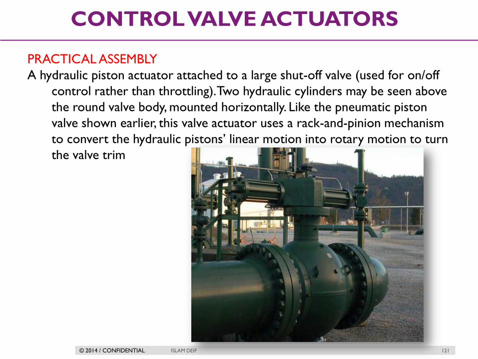
PRACTICAL ASSEMBLY
A hydraulic piston actuator attached to a large shut-off valve (used for on/off
control rather than throttling). Two hydraulic cylinders may be seen above
the round valve body, mounted horizontally. Like the pneumatic piston
valve shown earlier, this valve actuator uses a rack-and-pinion mechanism
to convert the hydraulic pistons’ linear motion into rotary motion to turn
the valve trim

© 2014 / CONFIDENTIAL ISLAM DEIF 122
CONTROL VALVE ACTUATORS
Electric Actuators (MOV)
Electric operators with proportional or infinite positioning control have
limited use in the process industries. Their primary use has been in remote
areas, such as tank farms and pipeline stations, where no convenient air supply
is available. Slow operating speeds, maintenance problems in hazardous areas
and economics have prevented wide acceptance for throttling applications.
Electric motors have long been used to actuate large valves, especially valves
operated as on/off (“shutoff”) devices. Advances in motor design and motor
control circuitry have brought motor operated valve (MOV) technology to
the point where it now competes with legacy actuator technologies such as
pneumatic in actuating throttling valves as well.

© 2014 / CONFIDENTIAL ISLAM DEIF 123
CONTROL VALVE ACTUATORS
An electric actuator providing on/off
rotary actuation to a ball valve. This
particular electric actuator comes with a
hand crank for manual operation, in the
event that the electric motor (or the
power provided to it) fails

© 2014 / CONFIDENTIAL ISLAM DEIF 124
CONTROL VALVE ACTUATORS
Electric motors require no external fluid power system to function, unlike
pneumatic or hydraulic actuators. All they require is a source of electrical
power (often 480 volts AC, three-phase). Some electric valve actuators even
have the capability of operating from the power of an electric battery pack, for
reliable operation in the event of a power system outage. Virtually all electric
valve actuators require some form of feedback to indicate the valve’s position.
At minimum, this consists of limit switches to indicate when the valve is fully
shut and fully open. For throttling services, an electric actuator requires an
actual valve position sensor so that it may precisely adjust the valve to any
desired state. This sensor may take the form of a potentiometer, or a variable
differential transformer (LVDT or RVDT)

© 2014 / CONFIDENTIAL ISLAM DEIF 125
CONTROL VALVE ACTUATORS
Hand Actuators
The most common manual actuators are:
Hand wheel—for linear motion valves: gate valves, globe valves.
lever—for rotational motion valves: ball valves, butterfly valves.
It can be operate normally with all type of valves

© 2014 / CONFIDENTIAL ISLAM DEIF 126
CONTROL VALVE ACTUATORS
Some examples for manual actuator

© 2014 / CONFIDENTIAL ISLAM DEIF 127
CONTROL VALVE ACTUATORS
Self Actuated Valves
Although not a type of actuator itself, a form of actuation worthy of mention
is where the process fluid pressure itself actuates a valve mechanism. This
self-operating principle may be used in throttling applications or on/off
applications, in gas or liquid services alike. The process fluid may be
directly tubed to the actuating element (diaphragm or piston), or passed
through a small mechanism called a pilot to modulate that pressure
before reaching the valve actuator. This latter design allows the main
valve’s motion to be controlled by an adjustable device (the pilot).

© 2014 / CONFIDENTIAL ISLAM DEIF 128
CONTROL VALVE ACTUATORS
Self-operated, spring-loaded gas pressure regulating valve
A spring tries to force the plug off the seat, while “feedback” gas pressure
from the downstream side of the valve acts against a flexible diaphragm to
move the plug toward the seat.
The less downstream pressure, the more the trim opens up; the more
downstream pressure, the more the trim shuts off. This spring establishes the
pressure-regulating “setpoint” value for the regulator.

© 2014 / CONFIDENTIAL ISLAM DEIF 129
CONTROL VALVE ACTUATORS
Pilot-loaded or externally-loaded pressure regulator
Externally supplied loading pressure does that. Since this loading pressure is
easily adjusted by turning the knob on the manual-set pressure regulator,
the main regulator now becomes adjustable as well. The pilot mechanism
controls the main gas throttling mechanism, hence the name pilot.

© 2014 / CONFIDENTIAL ISLAM DEIF 130
CONTROL VALVE ACTUATORS
Actuator types symbols
© 2014 / CONFIDENTIAL
VALVE FAILURE
MODES
ISLAM DEIF 131
© 2014 / CONFIDENTIAL ISLAM DEIF 132
VALVE FAILURE MODES
What is the meaning Failure ?!
By failure we mean the loss of the source of the actuating power supplied to
the valve body .
For electrically actuated valves, this is typically the last position the valve was
in before loss of electric power.
For pneumatic and hydraulic actuated valves, the option exists of having a large
spring provide a known “fail-safe” position (either open or closed) in the
event of fluid pressure (pneumatic air pressure or hydraulic oil pressure) loss.

© 2014 / CONFIDENTIAL ISLAM DEIF 133
VALVE FAILURE MODES
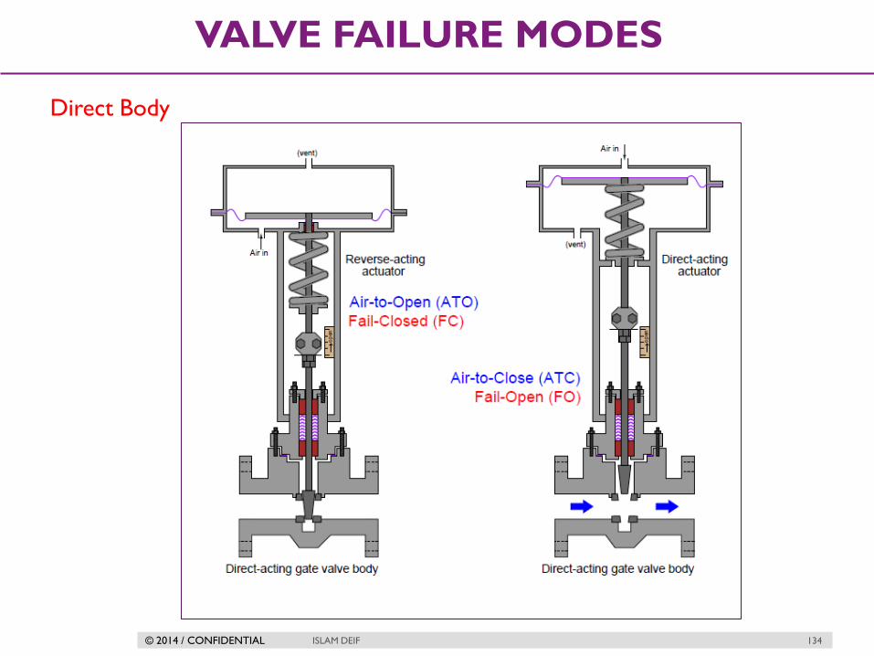
Direct/Reverse actions
The fail-safe mode of a pneumatic/spring valve is a function of both the
actuator’s action and the valve body’s action.
For sliding-stem valves
1st Actuator :
A direct-acting actuator pushes down on the stem with increasing pressure
while a reverse-acting actuator pulls up on the stem with increasing pressure.
2nd Valve Body
Sliding-stem valve bodies are classified as direct-acting if they open up when
the stem is lifted, and classified as reverse-acting if they shut off (close) when
the stem is lifted.
© 2014 / CONFIDENTIAL ISLAM DEIF 134
VALVE FAILURE MODES
Direct Body

© 2014 / CONFIDENTIAL ISLAM DEIF 135
VALVE FAILURE MODES
Reverse Body
© 2014 / CONFIDENTIAL ISLAM DEIF 136
VALVE FAILURE MODES
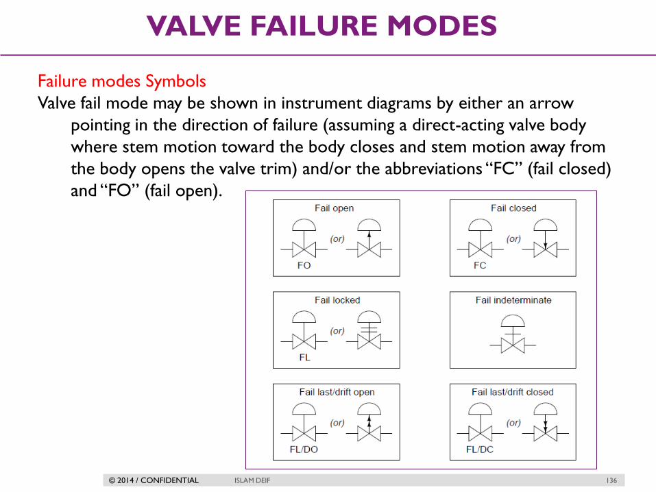
Failure modes Symbols
Valve fail mode may be shown in instrument diagrams by either an arrow
pointing in the direction of failure (assuming a direct-acting valve body
where stem motion toward the body closes and stem motion away from
the body opens the valve trim) and/or the abbreviations “FC” (fail closed)
and “FO” (fail open).

© 2014 / CONFIDENTIAL ISLAM DEIF 137
VALVE FAILURE MODES
How to select failure mode for a control valve
In fact, this basic principle forms the basis of decisions made for all instrument
actions in critical control loops: first determine the safest mode of valve
failure, then select and/or configure instrument actions in such a way that
the most probable modes of signal path failure will result in the control
valve consistently moving to that (safest) position.
Practical Example

© 2014 / CONFIDENTIAL
ACTUATOR
BENCH-SET
ISLAM DEIF 138

© 2014 / CONFIDENTIAL ISLAM DEIF 139
ACTUATOR BENCH-SET
Valve actuators provide force to move control valve trim. For precise
positioning of a control valve, there must be a calibrated relationship between
applied force and valve position. Most pneumatic actuators exploit Hooke’s
Law to translate applied air pressure to valve stem position.
F = kx
Where,
F = Force applied to spring in newtons (metric) or pounds (British)
k = Constant of elasticity, or “spring constant” in newtons per meter (metric)
or pounds perfoot (British)
x = Displacement of spring in meters (metric) or feet (British)
© 2014 / CONFIDENTIAL ISLAM DEIF 140
ACTUATOR BENCH-SET
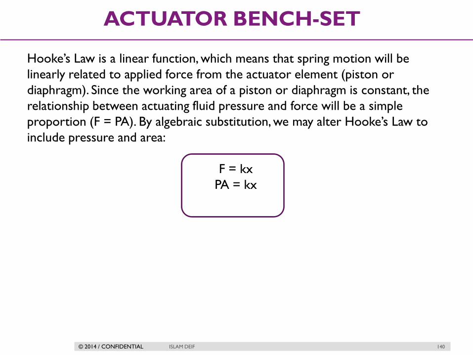
Hooke’s Law is a linear function, which means that spring motion will be
linearly related to applied force from the actuator element (piston or
diaphragm). Since the working area of a piston or diaphragm is constant, the
relationship between actuating fluid pressure and force will be a simple
proportion (F = PA). By algebraic substitution, we may alter Hooke’s Law to
include pressure and area:
F = kx
PA = kx

© 2014 / CONFIDENTIAL ISLAM DEIF 141
ACTUATOR BENCH-SET
Bench-Set Adjust

© 2014 / CONFIDENTIAL ISLAM DEIF 142
ACTUATOR BENCH-SET
Bench-Set Adjust
There are really only two mechanical adjustments that need to be made when
coupling a pneumatic diaphragm actuator to a sliding-stem valve: the stem
connector and the spring adjuster.

© 2014 / CONFIDENTIAL ISLAM DEIF 143
ACTUATOR BENCH-SET
Case 1

© 2014 / CONFIDENTIAL ISLAM DEIF 144
ACTUATOR BENCH-SET
Case 2

© 2014 / CONFIDENTIAL ISLAM DEIF 145
ACTUATOR BENCH-SET
Summary
Once the stem length has been properly set by adjusting the stem connector,
the spring adjuster must be set for the proper bench set pressure. This is the
pneumatic signal pressure required to lift the plug off the seat. For an air-to-
open control valve with a 3 to 15 PSI signal range, the “bench set” pressure
would be 3 PSI.
Bench set is a very important parameter for a control valve because it
establishes the seating force of the plug against the seat when the valve is fully
closed. Proper seating pressure is critical for tight shut-off, which carries safety
implications in some process services.

© 2014 / CONFIDENTIAL
ACTUATOR
RESPONSE
ISLAM DEIF 146

© 2014 / CONFIDENTIAL ISLAM DEIF 147
ACTUATOR RESPONSE
Actuator response problem
A limitation inherent to pneumatic valve actuators is the amount of air flow
required to or from the actuator to cause rapid valve motion. This is an
especially acute problem in all-pneumatic control systems, where the distance
separating a control valve from the controller may be large.
This was serious problem in pneumatic control systems .
© 2014 / CONFIDENTIAL ISLAM DEIF 148
ACTUATOR RESPONSE
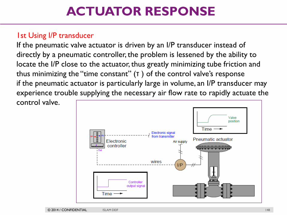
1st Using I/P transducer
If the pneumatic valve actuator is driven by an I/P transducer instead of
directly by a pneumatic controller, the problem is lessened by the ability to
locate the I/P close to the actuator, thus greatly minimizing tube friction and
thus minimizing the “time constant” (τ ) of the control valve’s response
if the pneumatic actuator is particularly large in volume, an I/P transducer may
experience trouble supplying the necessary air flow rate to rapidly actuate the
control valve.

© 2014 / CONFIDENTIAL ISLAM DEIF 149
ACTUATOR RESPONSE
I/P transducer
A “current to pressure” transducer (I/P) converts an analog signal (4 to 20
mA) to a proportional linear pneumatic output (3 to 15 psig). Its purpose is to
translate the analog output from a control system into a precise, repeatable
pressure value to control pneumatic actuators.
The I/P converter uses an electromagnetic force balance principle to change
electrical signals into pneumatic signals. Typically, a 4 – 20mA input is
converted into a 3 – 15pisg output.

© 2014 / CONFIDENTIAL ISLAM DEIF 150
ACTUATOR RESPONSE
2nd Using Volume booster
One way to improve valve response in either type of system is to use a device
known as a volume booster to source and vent compressed air for the valve
actuator.
A “volume booster” is a pneumatic device designed to reproduce a pneumatic
pressure signal (1:1 ratio), but with far greater output flow capacity. A 3 to 15
PSI pneumatic pressure signal applied to the input of a volume booster will
result in an identical output signal but with greatly enhanced flow capacity.

© 2014 / CONFIDENTIAL ISLAM DEIF 151
ACTUATOR RESPONSE
Volume booster VS Pressure regulator
In either mechanism, an internal diaphragm senses output pressure and acts
against a restraining force to position an air flow throttling/venting
mechanism.

© 2014 / CONFIDENTIAL
CONTROL VALVE
POSITIONER
ISLAM DEIF 152

© 2014 / CONFIDENTIAL ISLAM DEIF 153
CONTROL VALVE POSITIONER
Why do we need a positioner ?
Springs work quite nicely to convert mechanical force into mechanical motion
(Hooke’s Law – F = kx) for valve actuators if and only if the sole forces
involved are the diaphragm or piston force against the spring’s resistance
force. If any other force acts upon the system, the relationship between
actuating fluid pressure and valve stem travel will not necessarily be
proportional.

© 2014 / CONFIDENTIAL ISLAM DEIF 154
CONTROL VALVE POSITIONER
Positioner is a control system ?!!!!
Positioners essentially act as control systems within themselves the valve’s
stem position is the process variable (PV), the command signal to the
positioner is the set point (SP), and the positioner’s signal to the valve
actuator is the manipulated variable (MV) or output.

© 2014 / CONFIDENTIAL ISLAM DEIF 155
CONTROL VALVE POSITIONER
Advantages of adding positioner
Accurate positioning of the valve stem
Ability to change the valve characteristics
Increase the speed of response (acting like volume booster )
Reverse the action of a valve
Tight shutoff (improve valve seating )

© 2014 / CONFIDENTIAL ISLAM DEIF 156
CONTROL VALVE POSITIONER
How can Positioner increase valve seating

© 2014 / CONFIDENTIAL ISLAM DEIF 157
CONTROL VALVE POSITIONER
Electronic positioners
Electronic valve positioners, such as the Fisher model DVC6000, use an
electronic sensor to detect valve stem position, microprocessor to compare
that sensed stem position against the control
signal by mathematical subtraction (error = position − signal), then a
pneumatic signal converter and relay(s) to send air pressure to the valve
actuator.

© 2014 / CONFIDENTIAL ISLAM DEIF 158
CONTROL VALVE POSITIONER
Examples for electronic positioner

© 2014 / CONFIDENTIAL ISLAM DEIF 159
CONTROL VALVE POSITIONER
Examples for Pneumatic positioner

© 2014 / CONFIDENTIAL ISLAM DEIF 160
SOLENOID VALVES
Solenoid Valve
A very common form of on/off valve used for pneumatic and hydraulic
systems alike is the solenoid valve.
A “solenoid” is nothing more than a coil of wire designed to produce a
magnetic field when energized. Solenoid actuators work by attracting a
movable iron armature into the center of the solenoid coil when energized,
the force of this attraction working to actuate a small valve mechanism.
Solenoid-actuated valves are usually classified according to the number of
ports (“ways”). A simple on/off solenoid valve controlling flow into one port
and out of another port is called a 2-way valve. Another style of solenoid
valve, where flow is directed in one path or to another path – much like a
single-pole double-throw (SPDT) electrical switch – is called a 3-way valve
because it has three fluid ports.

© 2014 / CONFIDENTIAL ISLAM DEIF 161
SOLENOID VALVES
2-way solenoid valve
2-way solenoid valves operate in a manner analogous to single-pole single-
throw (SPST) electrical switches: with only one path for flow.

© 2014 / CONFIDENTIAL ISLAM DEIF 162
SOLENOID VALVES
3-way solenoid valves
3-way solenoid valves operate in a manner analogous to single-pole double-
throw (SPDT) electrical switches: with two paths for flow sharing one
common terminal.

© 2014 / CONFIDENTIAL ISLAM DEIF 163
SOLENOID VALVES
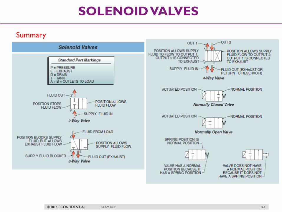
4-way solenoid valves
When a pneumatic actuator requires air pressure applied to two different
ports in order to move two different directions (such as the case for cylinders
lacking a return spring), the solenoid valve supplying air to that actuator must
have four ports: one for air supply (P), one for exhaust (E), and two for the
cylinder ports (typically labeled A and B).
the solenoid valve forces the piston-actuated valve stem to move down (shut
off) when the solenoid is de-energized. When the solenoid is energized, air is
directed to the bottom of the piston (with the top of the piston becoming
vented to atmosphere), causing the piston-actuated valve stem to move up
(open wide).
© 2014 / CONFIDENTIAL ISLAM DEIF 164
SOLENOID VALVES
Summary

© 2014 / CONFIDENTIAL ISLAM DEIF 165
PROXIMITY SWITCH
Proximity (limit) switch
A proximity switch is one detecting the proximity (closeness) of some object.
By definition, these switches are non-contact sensors, using magnetic, electric,
or optical means to sense the proximity of objects.
Inductive proximity switches sense the presence of metallic objects through
the use of a high-frequency magnetic field. Capacitive proximity switches sense
the presence of non-metallic objects through the use of a high-frequency
electric field. Optical proximity switches detect the interruption of a light
beam by an object. Ultrasonic proximity switches sense the presence of dense
matter by the reflection of sound waves.

© 2014 / CONFIDENTIAL ISLAM DEIF 166
PROXIMITY SWITCH
Proximity (limit) switch

© 2014 / CONFIDENTIAL ISLAM DEIF 167
PROXIMITY SWITCH
Quick Exhaust valve
It is used in case of quick venting is important in a control valve .

© 2014 / CONFIDENTIAL ISLAM DEIF 168
SPLIT RANGE CONTROL
Basic Control Strategies
Open loop control
Single feedback control
Cascade control
Ratio control
Split range control

© 2014 / CONFIDENTIAL ISLAM DEIF 169
SPLIT RANGE CONTROL
Split range Control
There are many process control applications in industry where it is desirable
to have multiple control valves respond to the output of a common controller.
Control valves configured to follow the command of the same controller are
said to be split-ranged, or sequenced. Split-ranged control valves may take
different forms of sequencing.
A few different modes of control valve sequencing are commonly seen in
industry:
Complementary
Exclusive
Progressive

© 2014 / CONFIDENTIAL ISLAM DEIF 170
SPLIT RANGE CONTROL
Complementary valve sequencing
A mode where two valves serve to proportion a mixture of two fluid streams.

© 2014 / CONFIDENTIAL ISLAM DEIF 171
SPLIT RANGE CONTROL
Exclusive valve sequencing
The nature of this valve sequencing is to have an “either-or” throttled path for
process fluid. That is, either process fluid flows through one valve or
through the other, but never through both at the same time.

© 2014 / CONFIDENTIAL ISLAM DEIF 172
SPLIT RANGE CONTROL
Progressive valve sequencing
This mode used to expand the operating range of flow control for some fluid
beyond that which a single control valve could muster.

© 2014 / CONFIDENTIAL ISLAM DEIF 173
CONTROL VALVE CHARACTERIZATION
Inherent versus installed characteristics
When control valves are tested in a laboratory setting, they are connected to
a piping system providing a nearly constant pressure difference between
upstream and downstream (P1 −P2). With a fluid of constant density
and a constant pressure drop across the valve, flow rate becomes a direct
function of flow coefficient (Cv).

© 2014 / CONFIDENTIAL ISLAM DEIF 174
CONTROL VALVE CHARACTERIZATION
Installed characteristics
When valves are installed with pumps, piping and fittings, and other process
equipment, the pressure drop across the valve will vary as the plug moves
through its travel.
When the actual flow in a system is plotted against valve opening, the curve is
called the Installed Flow Characteristic.
In most applications, when the valve opens, and the resistance due to fluids
flow decreases the pressure drop across the valve. This moves the inherent
characteristic:
A linear inherent curve will in general resemble a quick opening characteristic
An equal percentage curve will in general resemble a linear curve

© 2014 / CONFIDENTIAL ISLAM DEIF 175
CONTROL VALVE CHARACTERIZATION
Installed characteristics
Case 1

© 2014 / CONFIDENTIAL ISLAM DEIF 176
CONTROL VALVE CHARACTERIZATION
Installed characteristics
Case 2

© 2014 / CONFIDENTIAL ISLAM DEIF 177
CONTROL VALVE CHARACTERIZATION
Result
© 2014 / CONFIDENTIAL ISLAM DEIF 178
CONTROL VALVE CHARACTERIZATION
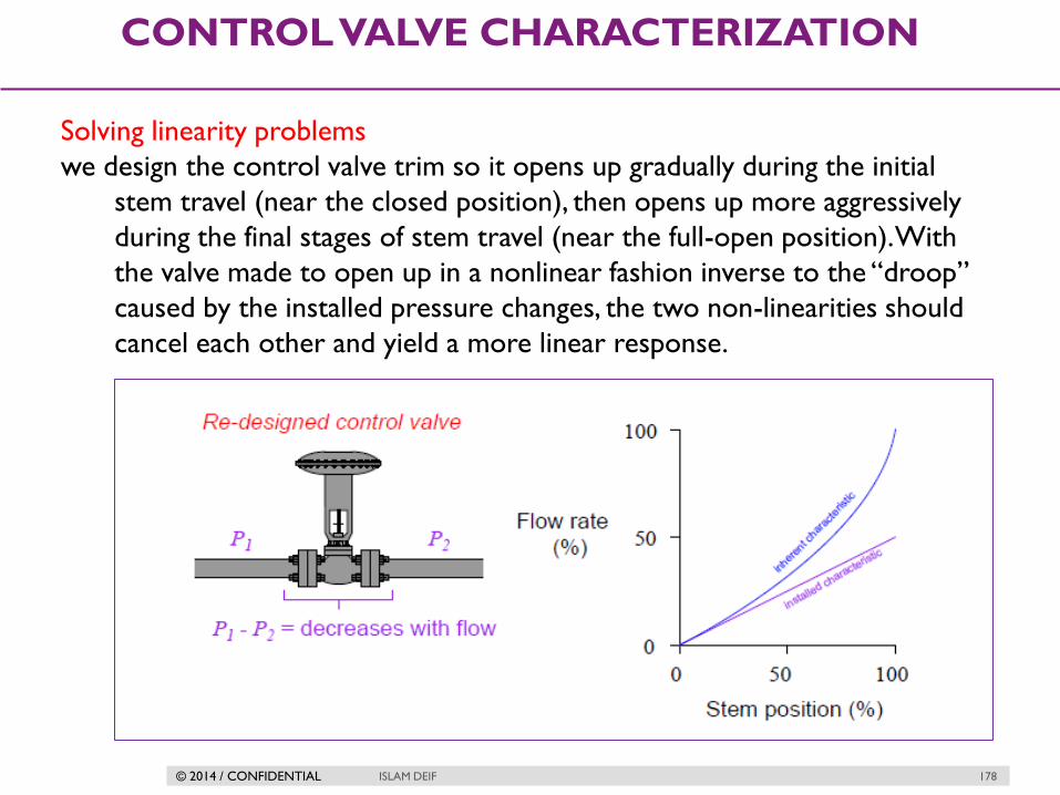
Solving linearity problems
we design the control valve trim so it opens up gradually during the initial
stem travel (near the closed position), then opens up more aggressively
during the final stages of stem travel (near the full-open position). With
the valve made to open up in a nonlinear fashion inverse to the “droop”
caused by the installed pressure changes, the two non-linearities should
cancel each other and yield a more linear response.
© 2014 / CONFIDENTIAL ISLAM DEIF 179
CONTROL VALVE CHARACTERIZATION
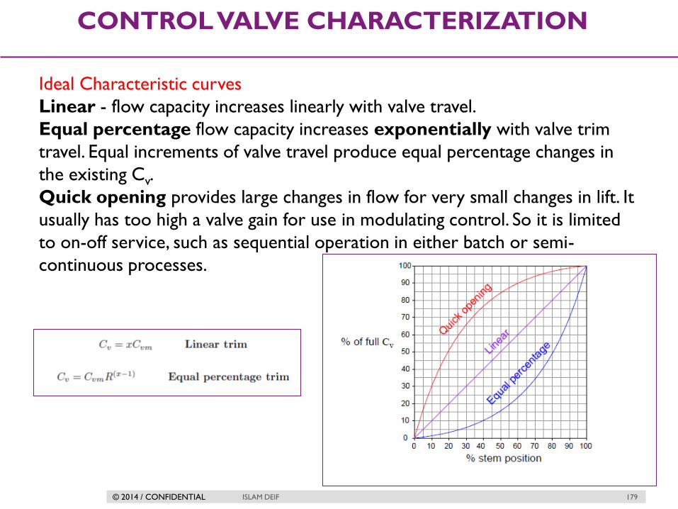
Ideal Characteristic curves
Linear - flow capacity increases linearly with valve travel.
Equal percentage flow capacity increases exponentially with valve trim
travel. Equal increments of valve travel produce equal percentage changes in
the existing Cv.
Quick opening provides large changes in flow for very small changes in lift. It
usually has too high a valve gain for use in modulating control. So it is limited
to on-off service, such as sequential operation in either batch or semi-
continuous processes.

© 2014 / CONFIDENTIAL ISLAM DEIF 180
CONTROL VALVE CHARACTERIZATION
Example
LINEAR CHARACTERISTIC CURVE

© 2014 / CONFIDENTIAL ISLAM DEIF 181
CONTROL VALVE CHARACTERIZATION
Example
Equal percentage

© 2014 / CONFIDENTIAL ISLAM DEIF 182
CONTROL VALVE CHARACTERIZATION
Modified characteristic curves
© 2014 / CONFIDENTIAL ISLAM DEIF 183
CONTROL VALVE CHARACTERIZATION
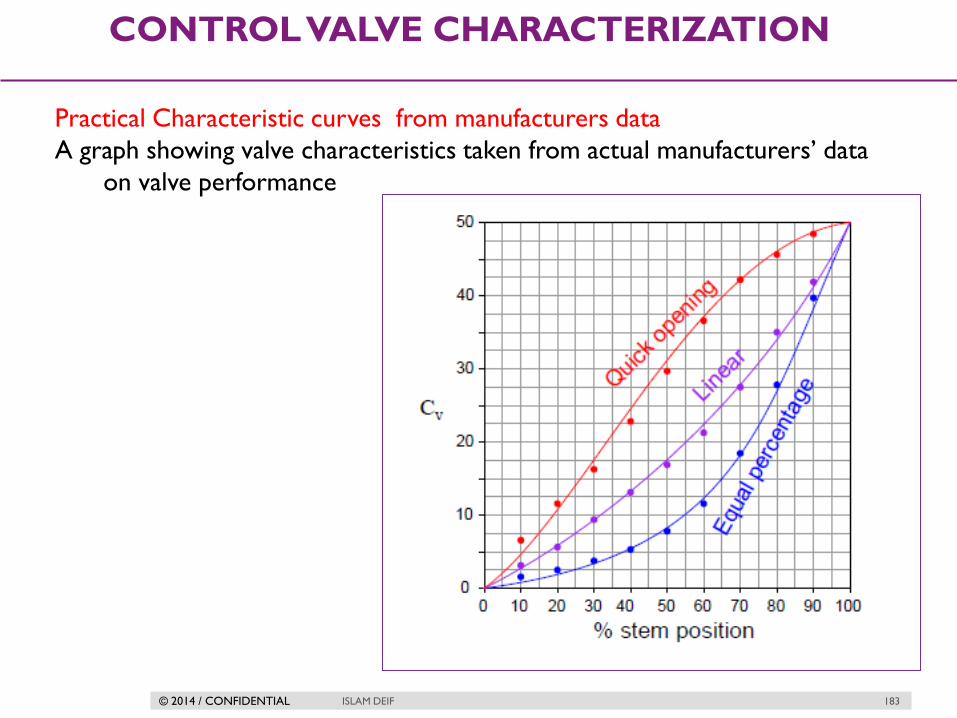
Practical Characteristic curves from manufacturers data
A graph showing valve characteristics taken from actual manufacturers’ data
on valve performance

© 2014 / CONFIDENTIAL ISLAM DEIF 184
CONTROL VALVE CHARACTERIZATION
Valve trim Assignments
Plug profiles of a single-ported, stem-guided globe valve may be modified to
achieve the common quick-opening, linear, and equal-percentage
characteristics

© 2014 / CONFIDENTIAL ISLAM DEIF 185
CONTROL VALVE CHARACTERIZATION
Cage guided

© 2014 / CONFIDENTIAL ISLAM DEIF 186
CONTROL VALVE CHARACTERIZATION
Ball valve trim
Ball Valve notch shapes in case of 50 % open

© 2014 / CONFIDENTIAL
SELECTION GUIDE
(CRACTERSISTIC
CURVE & BODY
TYPE
ISLAM DEIF 187

© 2014 / CONFIDENTIAL ISLAM DEIF 188
SELECTION GUIDE (CRACTERSISTIC CURVE & BODY TYPE
Notes about selection
When speaking of valves, it's easy to get lost in the terminology. Valve types
are used to describe the mechanical characteristics and geometry (Ex/ gate,
ball, globe valves). We'll use valve control to refer to how the valve travel or
stroke (openness) relates to the flow:
1. Equal Percentage: equal increments of valve travel produce an equal
percentage in flow change
2. Linear: valve travel is directly proportional to the valve stoke
3. Quick opening: large increase in flow with a small change in valve
stroke

© 2014 / CONFIDENTIAL ISLAM DEIF 189
SELECTION GUIDE (CRACTERSISTIC CURVE & BODY TYPE
Equal Percentage (most commonly used valve control)
a. Used in processes where large changes in pressure drop are expected
b. Used in processes where a small percentage of the total pressure drop is
permitted by the valve
c. Used in temperature and pressure control loops
Linear
a. Used in liquid level or flow loops
b. Used in systems where the pressure drop across the valve is expected to
remain fairly constant (ie. steady state systems)
Quick Opening
a. Used for frequent on-off service
b. Used for processes where "instantly" large flow is needed (ie. safety systems
or cooling water systems)

© 2014 / CONFIDENTIAL ISLAM DEIF 190
SELECTION GUIDE (CRACTERSISTIC CURVE & BODY TYPE
Gate valve
Gate Valves Best Suited Control: Quick Opening
Recommended Uses:
1. Fully open/closed, non-throttling
2. Infrequent operation
3. Minimal fluid trapping in line
Applications: Oil, gas, air, slurries, heavy liquids, steam, non condensing gases,
and corrosive liquids
Advantages:
• High capacity
• Tight shutoff
• Low cost
Disadvantages
• Poor control
• Cavitate at low pressure drops
• Cannot be used for throttling

© 2014 / CONFIDENTIAL ISLAM DEIF 191
SELECTION GUIDE (CRACTERSISTIC CURVE & BODY TYPE
Globe Valve
Best Suited Control: Linear and Equal percentage
Recommended Uses:
1. Throttling service/flow regulation
2. Frequent operation
Applications: Liquids, vapors, gases, corrosive substances, slurries
Advantages:
• Efficient throttling
• Accurate flow control
• Available in multiple ports
Disadvantages
• High pressure drop
• More expensive than other valves

© 2014 / CONFIDENTIAL ISLAM DEIF 192
SELECTION GUIDE (CRACTERSISTIC CURVE & BODY TYPE
Ball valve
Best Suited Control: Quick opening, linear
1. Fully open/closed, limited-throttling
2. Higher temperature fluids
Applications: Most liquids, high temperatures, slurries suited Control: Quick opening,
linear
Advantages:
• Low cost
• High capacity
• Low leakage and maint.
• Tight sealing with low torque
Disadvantages
• Poor throttling characteristics
• Prone to cavitation

© 2014 / CONFIDENTIAL ISLAM DEIF 193
SELECTION GUIDE (CRACTERSISTIC CURVE & BODY TYPE
Butterfly valve
Best Suited Control: Linear, Equal percentage
Recommended Uses:
1. Fully open/closed or throttling services
2. Frequent operation
3. Minimal fluid trapping in line
Applications: Liquids, gases, slurries, liquids with suspended solids
Advantages:
• Low cost and maint.
• High capacity
• Good flow control
• Low pressure drop Other Valves
Disadvantages
• High torque required for control
• Prone to cavitation at lower flows

© 2014 / CONFIDENTIAL ISLAM DEIF 194
SELECTION GUIDE (CRACTERSISTIC CURVE & BODY TYPE
Selection Steps

© 2014 / CONFIDENTIAL ISLAM DEIF 195
SELECTION GUIDE (CRACTERSISTIC CURVE & BODY TYPE
Selection Steps

© 2014 / CONFIDENTIAL ISLAM DEIF 196
SELECTION GUIDE (CRACTERSISTIC CURVE & BODY TYPE
Selection Steps

© 2014 / CONFIDENTIAL ISLAM DEIF 197
SELECTION GUIDE (CRACTERSISTIC CURVE & BODY TYPE
Selection Steps

© 2014 / CONFIDENTIAL ISLAM DEIF 198
SELECTION GUIDE (CRACTERSISTIC CURVE & BODY TYPE
Selection Steps

© 2014 / CONFIDENTIAL ISLAM DEIF 199
SELECTION GUIDE (CRACTERSISTIC CURVE & BODY TYPE
Selection Steps

© 2014 / CONFIDENTIAL
CONTROL VALVE
SIZING
ISLAM DEIF 200

© 2014 / CONFIDENTIAL ISLAM DEIF 201
CONTROL VALVE SIZING
What is Valve Sizing?
It is a procedure by which the dynamics of a process system are matched to
the performance characteristics of a valve.
This is to provide a control valve that will best meet the needs of
managing flow within that process system.

© 2014 / CONFIDENTIAL ISLAM DEIF 202
CONTROL VALVE SIZING
Flow Coefficient (CV)
The valve flow coefficient, CV is the number of U.S. gallons per minute of
water at 60 degrees F which will pass through a given flow restriction
with a pressure drop of 1 psi.
For example, a control valve which has a flow coefficient, or CV, of 12 has an
effective port area that it passes 12 gallons per minute of water with 1 psi
pressure drop.

© 2014 / CONFIDENTIAL ISLAM DEIF 203
CONTROL VALVE SIZING
Valve as a Variable Restriction

© 2014 / CONFIDENTIAL ISLAM DEIF 204
CONTROL VALVE SIZING
Pressure Drop

© 2014 / CONFIDENTIAL ISLAM DEIF 205
CONTROL VALVE SIZING
Flow Capacity Coefficient Cv
Hence we can show that the flow versus square root or pressure drop
relationship for any valve is given in the form shown as a straight line
with slope Cv .

© 2014 / CONFIDENTIAL ISLAM DEIF 206
CONTROL VALVE SIZING
Choked flow conditions (critical flow)
Choked flow is also known as critical flow and It occurs when an increase in
pressure drop across the valve no longer creates an increase in flow.

© 2014 / CONFIDENTIAL ISLAM DEIF 207
CONTROL VALVE SIZING
Choked flow conditions (critical flow)
In liquid applications the capacity of the valve is severely limited if the pressure
conditions for a liquid are low enough to cause flashing and Cavitation.
For gases and vapors the capacity is limited if the velocity reaches the sonic
velocity.

© 2014 / CONFIDENTIAL ISLAM DEIF 208
CONTROL VALVE SIZING
Pressure Drop

© 2014 / CONFIDENTIAL ISLAM DEIF 209
CONTROL VALVE SIZING
Pressure Drop

© 2014 / CONFIDENTIAL ISLAM DEIF 210
CONTROL VALVE SIZING
Pressure Drop

© 2014 / CONFIDENTIAL ISLAM DEIF 211
CONTROL VALVE SIZING
Liquid sizing equation
Q = Volumetric flow rate of liquid (gallons per minute, GPM)
Cv = Flow coefficient of valve
P1 = Upstream pressure of liquid (PSI)
P2 = Downstream pressure of liquid (PSI)
Gf = Specific gravity of liquid (ratio of liquid density to standard water density)

© 2014 / CONFIDENTIAL ISLAM DEIF 212
CONTROL VALVE SIZING
Liquid Design Equations
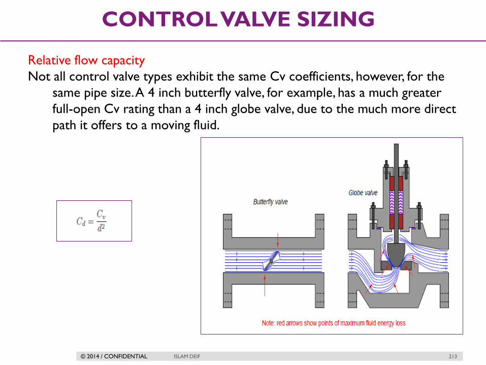
© 2014 / CONFIDENTIAL ISLAM DEIF 213
CONTROL VALVE SIZING
Relative flow capacity
Not all control valve types exhibit the same Cv coefficients, however, for the
same pipe size. A 4 inch butterfly valve, for example, has a much greater
full-open Cv rating than a 4 inch globe valve, due to the much more direct
path it offers to a moving fluid.

© 2014 / CONFIDENTIAL ISLAM DEIF 214
CONTROL VALVE SIZING
Typical values for relative flow coefficient

© 2014 / CONFIDENTIAL ISLAM DEIF 215
CONTROL VALVE SIZING
Steps To Accurately Size A Liquid Control Valve
1. Specify the required design flow rate
2. Specify the allowable pressure drop across the valve
3. Choose a valve type and body size from the manufacturers’ tables
4. Calculate the first estimate of the piping geometry factor
5. Determine if the flow through the valve will be sub-critical or critical. That
is, will some of the liquid vaporise causing flashing or cavitation?
6. Calculate the effective pressure drop across the valve
7. Calculate the first estimate of the required valve Cv
8. Check that the calculated Cv is less than the actual Cv of the selected
valve (re-select suitable valve from manufacturers’ tables if required)
9. Check that valve control range is OK
10. If the Cv and control range are suitable the valve is correctly sized. If not
re-select another valve and repeat the sizing procedure from Step 3

© 2014 / CONFIDENTIAL ISLAM DEIF 216
CONTROL VALVE SIZING
Control Valve Sizing Rules Of Thumb
1- Set the design flow as the greater of:
1.3 x normal flow rate
1.1 x maximum required flow rate
2- Set the control pressure drop to equal 50% – 60% of the frictional pressure
loss of the piping system
3- Limit the maximum flow rate : minimum flow rate turndown to 5:1 for
linear trim valves and 10:1 for equal percentage trim valves
4- The valve should be able to control the required range of flow rates
between 10% and 80% of valve opening
5- Ideally select a valve that has a body size 1 pipe size smaller than the pipe in
which it is to be installed (e.g. select a 3” valve for a 4” pipe)
6- Never select a valve larger than the pipe in which it is to be installed
© 2014 / CONFIDENTIAL ISLAM DEIF 217
CONTROL VALVE SIZING
What are the Control Valves sizing procedure?
STEP #1: Define the system
STEP #2: Define a maximum available (allowable) pressure drop for the valve
STEP #3: Calculate the valve flow coefficient
STEP #4: Preliminary valve selection
STEP #5: Check the Cv and stroke percentage at the minimum flow
STEP #6: Check the gain across applicable flow rates

© 2014 / CONFIDENTIAL ISLAM DEIF 218
CONTROL VALVE SIZING
Liquid Sizing Examples
Example 1
The following example has been adapted from the Emerson Control Valve
Handbook.
We need to size a valve in liquid propane duty. The required information is
given below:
Step 1 : Define the System
Design flow rate = 800 US gpm
Upstream pressure = 314.7 psia
Downstream pressure = 289.7 psia
Pressure drop across valve = 25 psi
Liquid temperature = 70F
Propane specific gravity = 0.5
Propane vapour pressure = 124.3 psia
Propane critical pressure = 616.3 psia
Pipe size = 4 inch

© 2014 / CONFIDENTIAL ISLAM DEIF 219
CONTROL VALVE SIZING
Liquid Sizing Examples
STEP #2 Define a maximum available (allowable) pressure drop for the valve
Pressure Drop = Upstream Pressure – Downstream Pressure
= 25 psi

© 2014 / CONFIDENTIAL ISLAM DEIF 220
CONTROL VALVE SIZING
Liquid Sizing Examples
STEP #3: Calculate the valve flow coefficient
Cv = (800 / 1)(0.5 / 25)0.5 = 117.9

© 2014 / CONFIDENTIAL ISLAM DEIF 221
CONTROL VALVE SIZING
Liquid Sizing Examples
STEP #4; Preliminary valve selection
We will choose an Emerson 3" ES globe valve with linear trim as the
preliminary selection. From the valve table we can see that the actual Cv
is 135 and FL is 0.89

© 2014 / CONFIDENTIAL ISLAM DEIF 222
CONTROL VALVE SIZING
Liquid Sizing Examples

© 2014 / CONFIDENTIAL ISLAM DEIF 223
CONTROL VALVE SIZING
Liquid Sizing Examples
Don't make the mistake of trying to match a valve with your calculated Cv
value. The Cv value should be used as a guide in the valve selection, not
a hard and fast rule. Some other considerations are:
a. Never use a valve that is less than half the pipe size
b. Avoid using the lower 10% and upper 20% of the valve stroke. The
valve is much easier to control in the 10-80% stroke range.
For our case, it appears the 3 inch valve will work well for our Cv value at
about 70-80% of the stroke range.
Notice that we're not trying to squeeze our Cv into the 3 inch valve which
would need to be more than 100% stroke to handle our maximum flow.
The calculated required Cv of 113.1 is less than the actual Cv of the selected
valve of 135 so the valve is large enough.

© 2014 / CONFIDENTIAL ISLAM DEIF 224
CONTROL VALVE SIZING
Liquid Sizing Examples
Calculating Piping Geometry Factor. Fp
We will assume that 4” x 3” reducers will be used to install the selected 3”
valve in the 4” pipe. In this case the piping geometry factor is:
ΣK = 1.5 (1 – (32 / 42))2 = 0.287
FP = [1 + (0.287 / 890)(135 / 32)2]-0.5 = 0.96

© 2014 / CONFIDENTIAL ISLAM DEIF 225
CONTROL VALVE SIZING
Liquid Sizing Examples
Check if flow through the valve is sub-critical or critical:
FF = 0.96 – 0.28 (124.3 / 616.3) = 0.83
DPmax = (0.89)2 (314.7 – 0.83 x 124.3) = 167.6 psi
P1 – P2 = 314.7 – 289.7 = 25 psi
Therefore: P1 – P2 < DPmax so the flow is sub-critical
The effective pressure drop across the valve is P1 – P2 because the flow is sub-
critical
DPeff =25 psi
© 2014 / CONFIDENTIAL ISLAM DEIF 226
CONTROL VALVE SIZING
Liquid Sizing Examples
Calculate the first estimate of Cv:
Cv = (800 / 0.96)(0.5 / 25)0.5 = 117.9
The calculated required Cv of 117.9 is less than the actual Cv of the selected
valve of 135 so the valve is large enough
Check if the control valve range is OK:
From the valve table, the selected valve will be about 75% open to give the
required Cv of 117.9. This is within the acceptable control range of 10% to
80% of valve opening.
The selected 3” linear trim valve is correctly sized for the specified duty

© 2014 / CONFIDENTIAL ISLAM DEIF 227
CONTROL VALVE SIZING
Example 2
STEP #1: Define the system
The system is pumping water from one tank to another through a
piping system with a total pressure drop of 150 psi. The fluid is water at
70 0F. Design (maximum) flowrate of 150 gpm, operating flowrate of 110
gpm, and a minimum flowrate of 25 gpm. The pipe diameter is 3
inches. At 70 0F, water has a specific gravity of 1.0.
Key Variables: Total pressure drop, design flow, operating flow, minimum flow,
pipe diameter, specific gravity

© 2014 / CONFIDENTIAL ISLAM DEIF 228
CONTROL VALVE SIZING
Example 2
STEP #2: Define a maximum allowable pressure drop for the valve
When defining the allowable pressure drop across the valve, you should
first investigate the pump. What is its maximum available
head? Remember that the system pressure drop is limited by the
pump. Essentially the Net Positive Suction Head Available (NPSHA)
minus the Net Positive Suction Head Required (NPSHR) is the maximum
available pressure drop for the valve to use and this must not be
exceeded or another pump will be needed.
The usual rule of thumb is that a valve should be designed to use 10-15% of
the total pressure drop or 10 psi, whichever is greater. For our system,
10% of the total pressure drop is 15 psi which is what we'll use as our
allowable pressure drop when the valve is wide open (the pump is our
system is easily capable of the additional pressure drop).

© 2014 / CONFIDENTIAL ISLAM DEIF 229
CONTROL VALVE SIZING
Example 2
STEP #3: Calculate the valve characteristic
For our system,
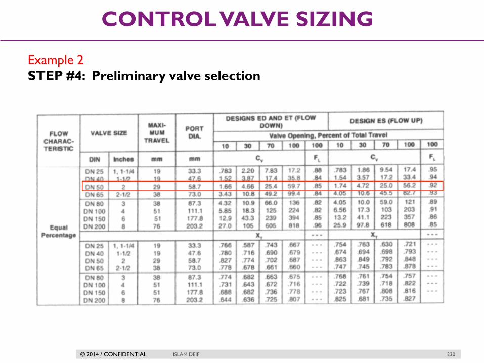
© 2014 / CONFIDENTIAL ISLAM DEIF 230
CONTROL VALVE SIZING
Example 2
STEP #4: Preliminary valve selection

© 2014 / CONFIDENTIAL ISLAM DEIF 231
CONTROL VALVE SIZING
Design in steps
Specify the variables required to size the
valve as follows
Determine the equation constant, N
Determine Fp, the piping geometry
factor
Determine Qmax or ΔPmax
Solve for required Cv, using the appropriate
equation:
Select the valve size using the appropriate flow coefficient table and the calculated
Cv value.

© 2014 / CONFIDENTIAL ISLAM DEIF 232
CONTROL VALVE SIZING
Design steps in details
STEP 1
Specify the variables required to size the valve as follows:
Desired design: refer to the appropriate valve flow coefficient table.
Process fluid (water, oil, etc.).
Appropriate service conditions q or w, P1, P2 or ΔP, T1, Gf, Pv, Pc, and υ

© 2014 / CONFIDENTIAL ISLAM DEIF 233
CONTROL VALVE SIZING
STEP 2
Determine the equation constant, N. N is a numerical constant contained in
each of the flow equations to provide a means for using different systems
of units.

© 2014 / CONFIDENTIAL ISLAM DEIF 234
CONTROL VALVE SIZING
STEP 3
Determine Fp, the piping geometry factor

© 2014 / CONFIDENTIAL ISLAM DEIF 235
CONTROL VALVE SIZING
STEP 4
Determine qmax (the maximum flow rate at given upstream conditions) or
ΔPmax (the allowable sizing pressure drop).
STEP 5
Solve for required Cv, using the appropriate equation:
STEP 6
Select the valve size using the appropriate flow coefficient table and the
calculated Cv value.

© 2014 / CONFIDENTIAL ISLAM DEIF 236
CONTROL VALVE SIZING
Gas sizing equations
q = Gas flow rate, in units of Standard Cubic Feet per Hour (SCFH)
Cv = Valve capacity coefficient
∆P = Pressure dropped across valve, pounds per square inch differential
(PSID)
P1 = Upstream valve pressure, pounds per square inch absolute (PSIA)
P2 = Downstream valve pressure, pounds per square inch absolute (PSIA)
Gg = Specific gravity of gas (ratio of gas density to standard air density)
T1 = Absolute temperature of gas in degrees Rankine (oR), equal to degrees
Fahrenheit plus 459.67
Fp = the piping geometry factor.
Y = expanison factor
Z = compressibility factor
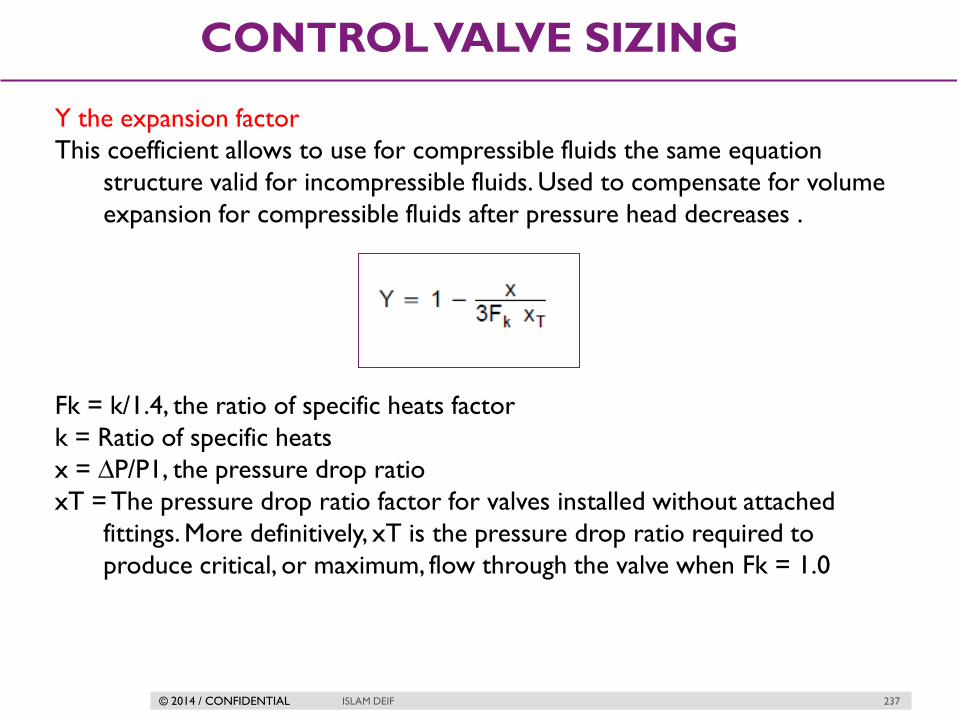
© 2014 / CONFIDENTIAL ISLAM DEIF 237
CONTROL VALVE SIZING
Y the expansion factor
This coefficient allows to use for compressible fluids the same equation
structure valid for incompressible fluids. Used to compensate for volume
expansion for compressible fluids after pressure head decreases .
Fk = k/1.4, the ratio of specific heats factor
k = Ratio of specific heats
x = ∆P/P1, the pressure drop ratio
xT = The pressure drop ratio factor for valves installed without attached
fittings. More definitively, xT is the pressure drop ratio required to
produce critical, or maximum, flow through the valve when Fk = 1.0

© 2014 / CONFIDENTIAL ISLAM DEIF 238
CONTROL VALVE SIZING
The Ratio of Specific Heats
The Ratio of Specific Heats can be expressed as:
k = cp / cv

© 2014 / CONFIDENTIAL ISLAM DEIF 239
CONTROL VALVE SIZING
XTP the Pressure Drop Ratio Factor
xTP is the same coefficients xT however determined on valves supplied with
reducers or installed not in according to the standard set up.
N5 = Numerical constant found in the Equation Constants table
d = Assumed nominal valve size
Cv = Valve sizing coefficient from flow coefficient table at 100 percent travel
for the assumed valve size
Fp = Piping geometry factor
xT = Pressure drop ratio for valves installed without fittings attached.
xT values are included in the flow coefficient tables

© 2014 / CONFIDENTIAL ISLAM DEIF 240
CONTROL VALVE SIZING
Pressure drop limit !
pressure drop are realized when the value of x becomes equal to or exceeds
the appropriate value of the product of either Fk xT or Fk xTP at which
point:
Although in actual service, pressure drop ratios can, and often will exceed the
indicated critical values, this is the point where critical flow conditions
develop Thus, for a constant P1, decreasing P2 (i.e., increasing P) will not
result in an increase in the flow rate through the valve. Values of x,
therefore, greater than the product of either FkxT or FkxTP must
never be substituted in the expression for Y.
This means that Y can never be less than 0.667. This same limit on values of x
also applies to the flow equations that are introduced in the next section.

© 2014 / CONFIDENTIAL ISLAM DEIF 241
CONTROL VALVE SIZING
Compressibility factor (Z)
The compressibility factor (Z), also known as the compression factor, is the
ratio of the molar volume of a gas to the molar volume of an ideal gas at
the same temperature and pressure. It is a useful thermodynamic
property for modifying the ideal gas law to account for the real
gas behavior.

© 2014 / CONFIDENTIAL ISLAM DEIF 242
CONTROL VALVE SIZING
Sizing for gases in steps
Specify the variables required to size the
valve
Determine the equation constant, N
Determine Fp, the piping geometry
factor
Determine Y, the expansion factor.
Solve for required Cv, using the appropriate
equation:
Select the valve size using the appropriate flow coefficient table and the calculated
Cv value.

© 2014 / CONFIDENTIAL ISLAM DEIF 243
CONTROL VALVE SIZING
Sizing for gases in steps
Example
We need to size a valve in steam duty. The required information is given
below:
Design flow rate = 125000 lb/hr = 56689 kg/hr
Upstream pressure = 500 psig = 35.50 bara
Downstream pressure = 250 psig = 18.26 bara
Pressure drop across valve = 250 psi = 17.24 bar
Upstream steam temperature = 500F
Density of steam at upstream conditions = 1.0434 lb/ft3 = 16.71 kg/m3
Steam ratio of specific heat capacities = 1.28
Pipe size = 6 inch

© 2014 / CONFIDENTIAL ISLAM DEIF 244
CONTROL VALVE SIZING
Sizing for gases in steps
Example
Calculation
Design flow rate = 56689 kg/hr
Allowable pressure drop across the valve = 17.24 bar
We will choose an Emerson 4” ED globe valve with linear cage as the
preliminary selection. From the valve table we can see that the actual Cv is
236 and XTP is 0.688

© 2014 / CONFIDENTIAL ISLAM DEIF 245
CONTROL VALVE SIZING
Sizing for gases in steps
Valve specification

© 2014 / CONFIDENTIAL ISLAM DEIF 246
CONTROL VALVE SIZING
Sizing for gases in steps
Example
We will assume that 6” x 4” reducers will be used to install the selected 4”
valve in the 6” pipe. In this case the piping geometry factor is:
ΣK = 1.5 (1 – (42 / 62))2 = 0.463FP = [1 + (0.463 / 890)(236 / 42)2]-0.5 =
0.95
The pressure drop ratio factor, XT = 0.688
The inlet fittings head loss coefficient is:
Ki = 0.5 (1 – (42 / 62))2 + 1 – (4 / 6)4 = 0.957
So the modified pressure drop ratio factor is:
XTP = 0.688 / 0.952[1 + 0.688 x 0.957 / 1000 (236 / 42)2]-1 = 0.667
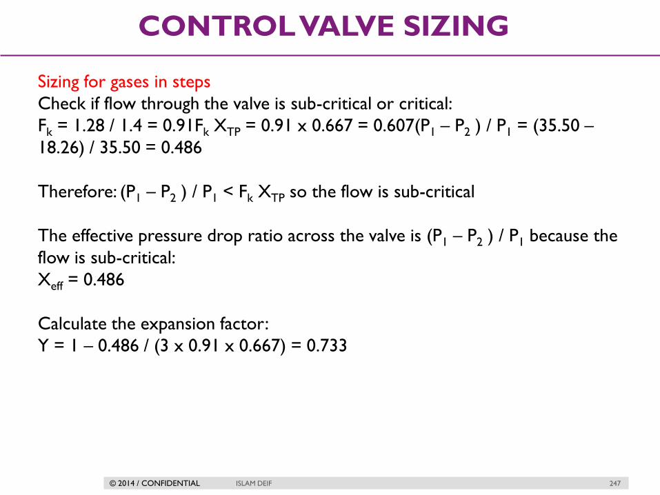
© 2014 / CONFIDENTIAL ISLAM DEIF 247
CONTROL VALVE SIZING
Sizing for gases in steps
Check if flow through the valve is sub-critical or critical:
Fk = 1.28 / 1.4 = 0.91Fk XTP = 0.91 x 0.667 = 0.607(P1 – P2 ) / P1 = (35.50 –
18.26) / 35.50 = 0.486
Therefore: (P1 – P2 ) / P1 < Fk XTP so the flow is sub-critical
The effective pressure drop ratio across the valve is (P1 – P2 ) / P1 because the
flow is sub-critical:
Xeff = 0.486
Calculate the expansion factor:
Y = 1 – 0.486 / (3 x 0.91 x 0.667) = 0.733

© 2014 / CONFIDENTIAL ISLAM DEIF 248
CONTROL VALVE SIZING
Sizing for gases in steps
Calculate the first estimate of Cv:
Cv = 56689 / (27.3 x 0.95 x 0.733 (0.486 x 35.50 x 16.71)0.5) = 175.6
The calculated required Cv of 175.6 is less than the actual Cv of the selected
valve of 236 so the valve is large enough
Check if the control valve range is OK:
From the valve table, the selected valve will be a just less 70% open to give the
required Cv of 175.6. This is within the acceptable control range of 10% to
80% of valve opening.
The selected 4” linear cage valve is correctly sized for the specified duty
Result
The selected valve is an Emerson 4” ED globe valve with linear trim and a
maximum Cv of 236.

© 2014 / CONFIDENTIAL
CONTROL VALVE
ENGINEERING
PROBLEMS
ISLAM DEIF 249

© 2014 / CONFIDENTIAL ISLAM DEIF 250
CONTROL VALVE ENGINEERING PROBLEMS
Stiction
Stiction is the combination of the words “stick” and “friction”.
Friction is classified as either static or dynamic.
When stiction is present it will keep a valve from moving for small changes in
its position command, and then when enough force is applied the
actuator overcomes the initial resistance and the valve jumps to a new
position.
Stiction is often the result of an actuator that is undersized or excessive
friction in the valve packing.

© 2014 / CONFIDENTIAL ISLAM DEIF 251
CONTROL VALVE ENGINEERING PROBLEMS
How stiction affect valve movement

© 2014 / CONFIDENTIAL ISLAM DEIF 252
CONTROL VALVE ENGINEERING PROBLEMS
Solutions
Avoid over tighten packing assembly to help in stopping leakage .
Smart positioners can adjust force supplied to actuator stem to help in
improving stiction problem
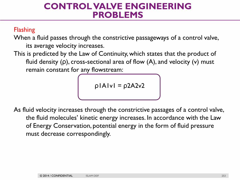
© 2014 / CONFIDENTIAL ISLAM DEIF 253
CONTROL VALVE ENGINEERING PROBLEMS
Flashing
When a fluid passes through the constrictive passageways of a control valve,
its average velocity increases.
This is predicted by the Law of Continuity, which states that the product of
fluid density (ρ), cross-sectional area of flow (A), and velocity (v) must
remain constant for any flowstream:
ρ1A1v1 = ρ2A2v2
As fluid velocity increases through the constrictive passages of a control valve,
the fluid molecules’ kinetic energy increases. In accordance with the Law
of Energy Conservation, potential energy in the form of fluid pressure
must decrease correspondingly.

© 2014 / CONFIDENTIAL ISLAM DEIF 254
CONTROL VALVE ENGINEERING PROBLEMS
What is flashing ?
If the fluid being throttled by the valve is a liquid (as opposed to a gas or
vapor), and its absolute pressure ever falls below the vapor pressure of
that substance, the liquid will begin to boil. This phenomenon, when it
happens inside a control valve, is called flashing.

© 2014 / CONFIDENTIAL ISLAM DEIF 255
CONTROL VALVE ENGINEERING PROBLEMS
Flashing is almost universally undesirable in control valves. The effect of boiling
liquid at the point of maximum constriction is that flow through the valve
becomes “choked” by the rapid expansion of liquid to vapor as it boils,
severely inhibiting the total flow rate allowed through the valve. Flashing is
also destructive to the valve trim, as boiling action propels tiny droplets of
liquid at extremely high velocities past the plug and seat faces, eroding the
metal over time.

© 2014 / CONFIDENTIAL ISLAM DEIF 256
CONTROL VALVE ENGINEERING PROBLEMS
Pressure recovery factor
This factor compares the valve’s total pressure drop from inlet to outlet
versus the pressure drop from inlet to the point of minimum pressure
within the valve.
Where,
FL = Pressure recovery factor (unitless)
P1 = Absolute fluid pressure upstream of the valve
P2 = Absolute fluid pressure downstream of the valve
Pvc = Absolute fluid pressure at the vena contracta
(point of minimum fluid pressure within the valve)

© 2014 / CONFIDENTIAL ISLAM DEIF 257
CONTROL VALVE ENGINEERING PROBLEMS
How can Fl affect on flashing

© 2014 / CONFIDENTIAL ISLAM DEIF 258
CONTROL VALVE ENGINEERING PROBLEMS
Effect of valve body on flashing

© 2014 / CONFIDENTIAL ISLAM DEIF 259
CONTROL VALVE ENGINEERING PROBLEMS
Cavitation
If fluid being throttled is a liquid, and the pressure at the vena contracta is less
than the vapor pressure of that liquid at the flowing temperature, the liquid
will spontaneously boil.
This is the phenomenon of flashing previously described. If, however, the
pressure recovers to a point greater than the vapor pressure of the liquid, the
vapor will re-condense back into liquid again. This is called cavitation.

© 2014 / CONFIDENTIAL ISLAM DEIF 260
CONTROL VALVE ENGINEERING PROBLEMS
Cavitation explanation
As destructive as flashing is to a control valve, cavitation is worse. When vapor
bubbles recondense into liquid they often do so asymmetrically, one side
of the bubble collapsing before the rest of the bubble. This has the effect
of translating the kinetic energy of the bubble’s collapse into a high-speed
“jet” of liquid in the direction of the asymmetrical collapse. These liquid
“microjets” have been experimentally measured at speeds up to 100
meters per second (over 320 feet per second).
What is more, the pressure applied to the surface of control valve
components in the path of these microjets is immense. Each microjet
strikes the valve component surface over a very small surface area,
resulting in a very high pressure (P = F/A) applied to that small area.
Pressure estimates as high as 1500 newtons per square millimeter (1.5 giga-
pascals, or about 220000 PSI!) have been calculated for control valve
applications involving water.

© 2014 / CONFIDENTIAL ISLAM DEIF 261
CONTROL VALVE ENGINEERING PROBLEMS
Effect of cavitation

© 2014 / CONFIDENTIAL ISLAM DEIF 262
CONTROL VALVE ENGINEERING PROBLEMS
Several methods exist for abating cavitation in control valves
1. Prevent flashing in the first place
2. Cushion with introduced gas
3. Sustain the flashing action

© 2014 / CONFIDENTIAL ISLAM DEIF 263
CONTROL VALVE ENGINEERING PROBLEMS
Preventing flashing
Select a control valve type having less pressure recovery (i.e. greater FL value)
• Increase both upstream and downstream pressures by relocating the valve
to a higher pressure location in the process.
• Use multiple control valves in series to reduce the lowest pressure at either
one
• Decrease the liquid’s temperature (this decreases vapor pressure)

© 2014 / CONFIDENTIAL ISLAM DEIF 264
CONTROL VALVE ENGINEERING PROBLEMS
Use cavitation-control valve trim
A valve equipped with cavitation-control trim will have a different pressure
profile, with multiple vena contracta points where the fluid passes
through a series of constrictions within the trim itself

© 2014 / CONFIDENTIAL ISLAM DEIF 265
CONTROL VALVE ENGINEERING PROBLEMS
Special trim design
This way, the same final permanent pressure drop (P1 −P2) may be achieved
without the lowest pressure ever falling below the liquid’s vapor pressure
limit.
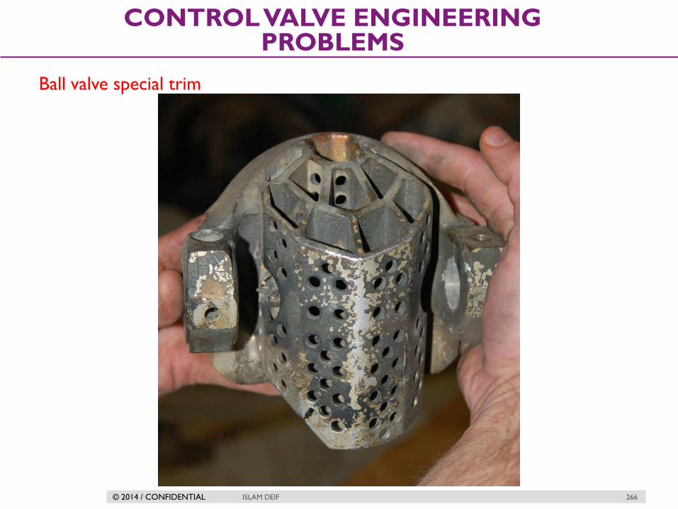
© 2014 / CONFIDENTIAL ISLAM DEIF 266
CONTROL VALVE ENGINEERING PROBLEMS
Ball valve special trim

© 2014 / CONFIDENTIAL ISLAM DEIF 267
CONTROL VALVE ENGINEERING PROBLEMS
Cushion with introduced gas
This Cavitation abatement method is practical only in some process
applications, where a non reacting gas may be injected into the liquid
stream to provide some “cushioning” within the cavitating region. The
presence of non-condensible gas bubbles in the liquid stream disturbs the
microjets’ pathways, helping to dissipate their energy before striking the
valve body walls.

© 2014 / CONFIDENTIAL ISLAM DEIF 268
CONTROL VALVE ENGINEERING PROBLEMS
Sustain the flashing action
This avoids cavitation at the cost of guaranteed flashing within the control
valve, which is generally not as destructive as cavitation.

© 2014 / CONFIDENTIAL ISLAM DEIF 269
CONTROL VALVE ENGINEERING PROBLEMS
Chocked flow
Both gas and liquid control valves may experience what is generally known as
choked flow. Simply put, “choked flow” is a condition where the rate of
flow through a valve does not change substantially as downstream
pressure is reduced.
In a gas control valve, choking occurs when the velocity of the gas reaches the
speed of sound for that gas. This is often referred to as critical or sonic
flow. In a liquid control valve, choking occurs with the onset of flashing.
The reason sonic velocity is relevant to flow capacity for a control valve has to
do with the propagation of pressure changes in fluids.
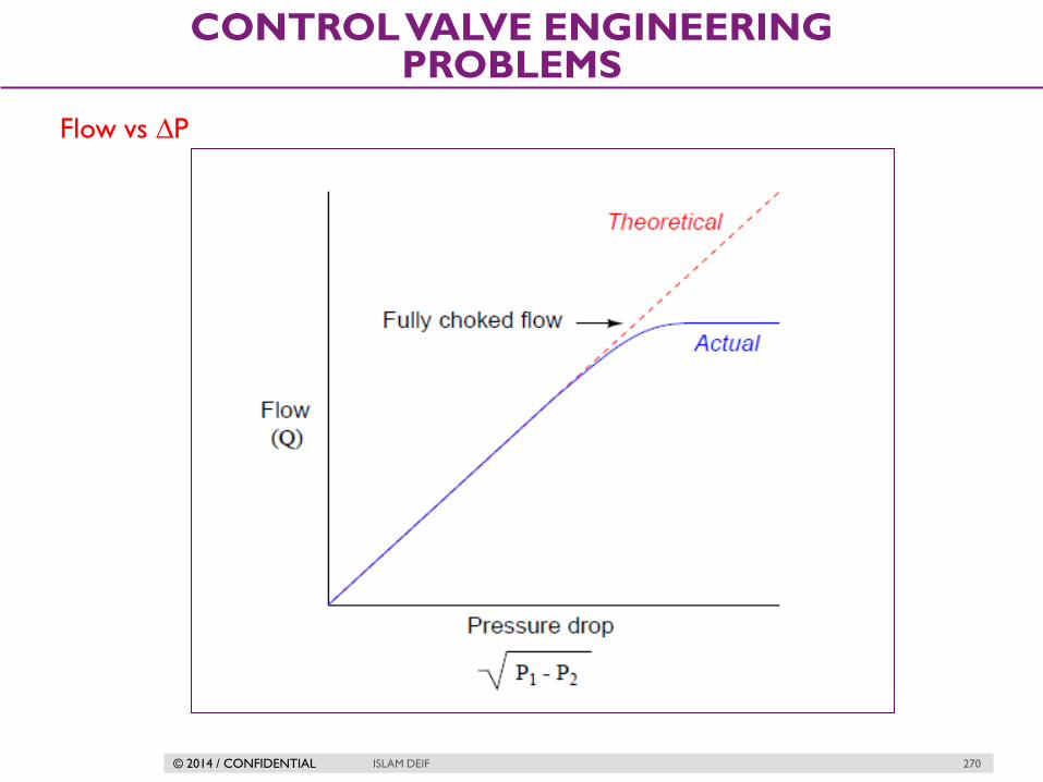
© 2014 / CONFIDENTIAL ISLAM DEIF 270
CONTROL VALVE ENGINEERING PROBLEMS
Flow vs ∆P

© 2014 / CONFIDENTIAL ISLAM DEIF 271
CONTROL VALVE ENGINEERING PROBLEMS
Notes
We may still increase flow rate through a choked valve by increasing its
upstream pressure.
An approximate predictor of choked flow conditions for gas valve service is
the upstream-to minimum absolute pressure ratio. When the vena contracta
pressure is less than one-half the upstream pressure, both measured in
absolute pressure units, choked flow is virtually guaranteed.
Choked flow in liquid services is predicted when the vena contracta pressure
equals the liquid’s vapor pressure, since choking is a function of flashing for
liquid flow streams.

© 2014 / CONFIDENTIAL ISLAM DEIF 272
CONTROL VALVE ENGINEERING PROBLEMS
Noise
A troublesome phenomenon in severe services is audible noise produced by
control valves. Noise output is worse for gas services experiencing sonic
(critical) flow and for liquid services experiencing cavitation, although it is
possible for a control valve to produce substantial noise even when
avoiding these operating conditions.

© 2014 / CONFIDENTIAL ISLAM DEIF 273
CONTROL VALVE ENGINEERING PROBLEMS
There are two strategies for reducing control valve noise:
1.Source control, that is doing something to the valve to make it less noisy.
-pressure drop staging
-flow division
2. Path control, that is doing something to prevent the noise from reaching the
people who would be bothered by it.

© 2014 / CONFIDENTIAL ISLAM DEIF 274
CONTROL VALVE ENGINEERING PROBLEMS
Pressure drop staging
The first method of source control of
aerodynamic noise is called "pressure drop
staging." Pressure drop staging means that
instead of taking the entire pressure drop
in one step, the pressure drop is divided up
into two or more steps. When the pressure
drop is taken in more than one step, the
individual velocity peaks are smaller than
the velocity peak that would result from a
single stage pressure drop. Because of the
strong relationship between noise and
velocity, small reductions in velocity can
have a large effect on reducing the noise.

© 2014 / CONFIDENTIAL ISLAM DEIF 275
CONTROL VALVE ENGINEERING PROBLEMS
Flow division
The second method of source control of aerodynamic noise is called "flow
division." Flow division means that instead of having the flow pass through
a single opening, the flow is divided up so that it passes through several
openings in parallel. Every time you double the number of openings, you
reduce the noise by 3 dBA. The reduction is due mainly to the fact that
the smaller openings shift the noise to a higher frequency. The higher
frequencies are attenuated more as the sound passes through the pipe
wall than are the lower frequencies. Also, because the human ear (and the
"A" weighting curve on noise meters) attenuate higher frequencies, both
the measured and perceived noise is decreased.
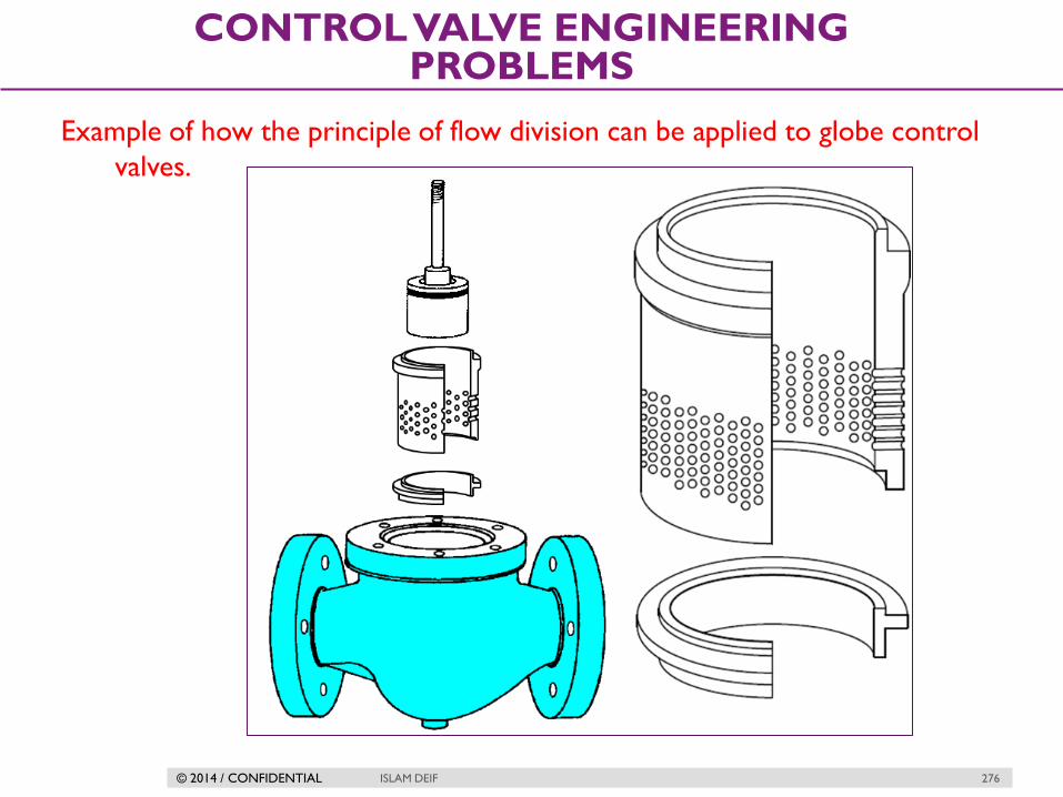
© 2014 / CONFIDENTIAL ISLAM DEIF 276
CONTROL VALVE ENGINEERING PROBLEMS
Example of how the principle of flow division can be applied to globe control
valves.

© 2014 / CONFIDENTIAL ISLAM DEIF 277
CONTROL VALVE ENGINEERING PROBLEMS
Combining both flow division and pressure drop staging for very noisy
applications.

© 2014 / CONFIDENTIAL ISLAM DEIF 278
CONTROL VALVE ENGINEERING PROBLEMS
Inline diffuser with ball valve

© 2014 / CONFIDENTIAL ISLAM DEIF 279
CONTROL VALVE ENGINEERING PROBLEMS
Special valve trim
A common cage-guided globe valve trim
design for noise reduction uses a
special cage designed with numerous,
small holes for process gas to flow
through. These small holes do not in
themselves reduce aerodynamic noise,
but they do shift the frequency of that
noise up. This increase in frequency
places the sound outside the range
where the human ear is most
sensitive to noise, and it also helps to
reduce noise coupling to the piping,
confining most of the noise “power”
to the internal volume of the process
fluid rather than radiating outward
into the air.

© 2014 / CONFIDENTIAL ISLAM DEIF 280
CONTROL VALVE ENGINEERING PROBLEMS
Path control
Distance : Most valve noise behaves as a line source. Most of the noise is
radiated from the downstream piping and the intensity of the noise remains
constant for long distances downstream.
Heavy wall pipe :The thicker the pipe wall, the more the noise is attenuated as
it passes through the pipe wall to where we hear it.
Thermal or acoustic insulation: Using thermal or acoustic insulation on the
piping downstream of a valve can reduce the sound pressure level that people
are exposed to.

© 2014 / CONFIDENTIAL ISLAM DEIF 281
CONTROL VALVE ENGINEERING PROBLEMS
Erosion
A problem common to control valves used in slurry service (where the
process fluid is a liquid containing a substantial quantity of hard, solid
particles) is erosion, where the valve trim and body are worn by the
passage of solid particles.
There really is no good way to reduce the effects of erosion damage from
slurry flows, other than to use exceptionally hard valve trim materials.

© 2014 / CONFIDENTIAL ISLAM DEIF 282
CONTROL VALVE ENGINEERING PROBLEMS
Another cause of erosion in control valves is wet steam, where steam
contains droplets of liquid water propelled at high velocity by the steam
flow.

© 2014 / CONFIDENTIAL ISLAM DEIF 283
CONTROL VALVE ENGINEERING PROBLEMS
Bonnet damage

© 2014 / CONFIDENTIAL ISLAM DEIF 284
CONTROL VALVE ENGINEERING PROBLEMS
Corrosion
Corrosive chemicals may attack the metal components of control valves if
those components are not carefully selected for the proper service.

© 2014 / CONFIDENTIAL ISLAM DEIF 285
CONTROL VALVE ENGINEERING PROBLEMS
Notes
The effects of corrosion are multiplied when combined with the effects of
cavitation. Most metals develop what is known as a passivation layer in
response to chemical attack. The outer layer of metal corrodes, but the
byproduct of that corrosion is a relatively inert compound acting to shield the
rest of the metal from further attack.
Rust on steel, or aluminum oxide on aluminum, are both common examples of
passivation layers in response to oxidation of the metal. When cavitation
happens inside a valve, however, the extremely high pressures caused by the
liquid microjets will blast away any protection afforded by the passivation layer,
allowing chemical attack to begin anew. The result is rapid degradation of the
valve components.

© 2014 / CONFIDENTIAL
INSTALLATION AND
MAINTENANCE
ISLAM DEIF 286

© 2014 / CONFIDENTIAL ISLAM DEIF 287
INSTALLATION AND MAINTENANCE
Introduction
Optimizing valve efficiency depends on:
Correct valve selection for the application,
Proper storage and protection,
Proper installation techniques, and
An effective maintenance program.
© 2014 / CONFIDENTIAL ISLAM DEIF 288
INSTALLATION AND MAINTENANCE
Proper Storage and Protection
Typically, manufacturers have packaging standards that are dependent
upon the destination and intended length of storage before installation.
The valve must be stored in a clean, dry place away from any traffic or
other activity that could damage the valve.

© 2014 / CONFIDENTIAL ISLAM DEIF 289
INSTALLATION AND MAINTENANCE
Proper Installation Techniques
Read the Instruction Manual
Instruction manuals describe the product and review safety issues and
precautions to be taken before and during installation.
Be Sure the Pipeline Is Clean
Foreign material in the pipeline could damage the seating surface of the
valve or even obstruct the movement of the valve plug, ball, or disk so
that the valve does not shut off properly.
Inspect pipe flanges to ensure a smooth gasket surface.
If the valve has screwed end connections, apply sealant compound to the
male pipeline only, not to the female valve threads. Excess compound
could cause sticking in the valve plug or accumulation of dirt

© 2014 / CONFIDENTIAL ISLAM DEIF 290
INSTALLATION AND MAINTENANCE
Proper Installation Techniques
Inspect the Valve
Do not install a valve known to have been damaged in shipment or while
in storage.
Before installing, check for and remove all shipping stops and protective
plugs or gasket surface covers.
Check inside the valve body to make sure no foreign objects are present.
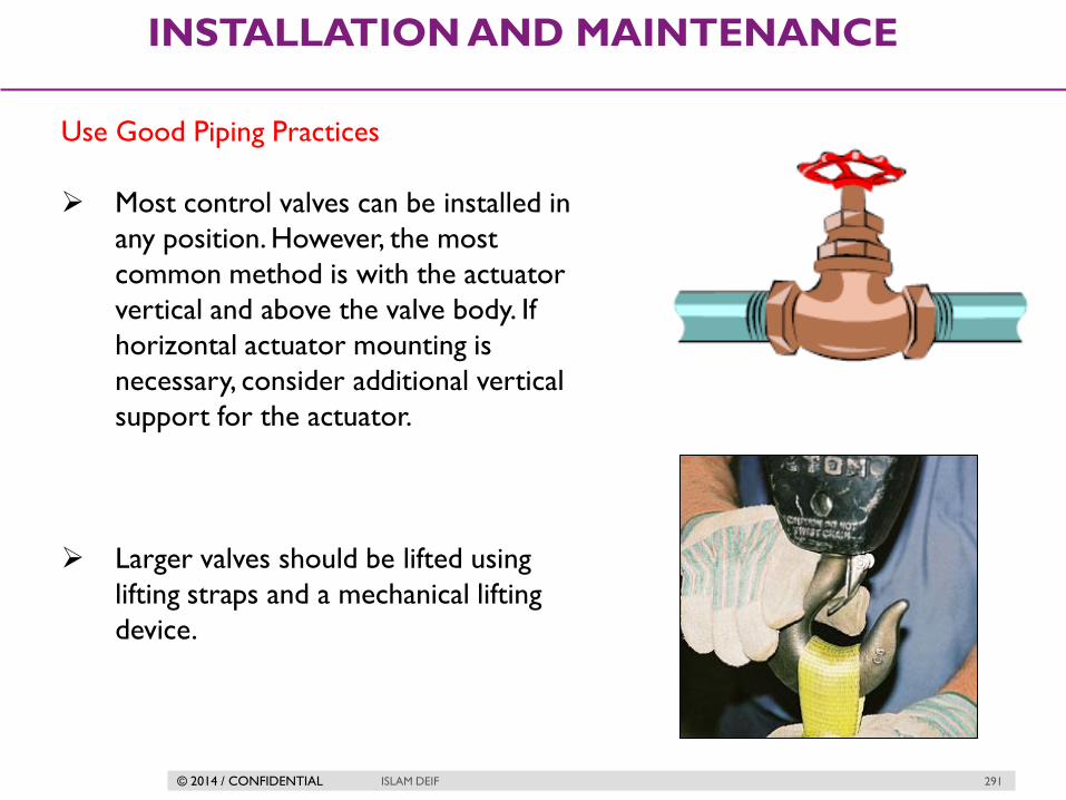
© 2014 / CONFIDENTIAL ISLAM DEIF 291
INSTALLATION AND MAINTENANCE
Use Good Piping Practices
Most control valves can be installed in
any position. However, the most
common method is with the actuator
vertical and above the valve body. If
horizontal actuator mounting is
necessary, consider additional vertical
support for the actuator.
Larger valves should be lifted using
lifting straps and a mechanical lifting
device.

© 2014 / CONFIDENTIAL ISLAM DEIF 292
INSTALLATION AND MAINTENANCE
Use Good Piping Practices
Be sure the body is installed so that fluid flow will be in the direction
indicated by the flow arrow.
Be sure to allow ample space above and below the valve to permit easy
removal of the actuator or valve plug for inspection and maintenance.
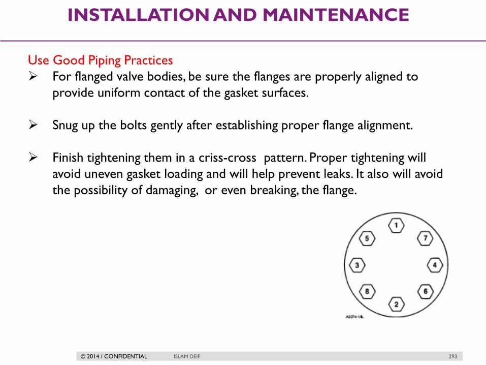
© 2014 / CONFIDENTIAL ISLAM DEIF 293
INSTALLATION AND MAINTENANCE
Use Good Piping Practices
For flanged valve bodies, be sure the flanges are properly aligned to
provide uniform contact of the gasket surfaces.
Snug up the bolts gently after establishing proper flange alignment.
Finish tightening them in a criss-cross pattern. Proper tightening will
avoid uneven gasket loading and will help prevent leaks. It also will avoid
the possibility of damaging, or even breaking, the flange.

© 2014 / CONFIDENTIAL ISLAM DEIF 294
INSTALLATION AND MAINTENANCE
Check operation
After installation, the manual operator should be used to fully stroke the
valve, observing the motion of the stem.
Check leakage
Check external leakage from the valve:
Compression packing.
Bonnet gasket or screw.
Flanges gasket.