process control - pressure and level switches, model 46926
TRANSCRIPT
Process Control
Pressure and Level Switches
Courseware Sample 86000-F0

Order no.: 86000-10
First Edition
Revision level: 03/2016
By the staff of Festo Didactic
© Festo Didactic Ltée/Ltd, Quebec, Canada 2010
Internet: www.festo-didactic.com
e-mail: [email protected]
Printed in Canada
All rights reserved
ISBN 978-2-89640-415-5 (Printed version)
Legal Deposit – Bibliothèque et Archives nationales du Québec, 2010
Legal Deposit – Library and Archives Canada, 2010
The purchaser shall receive a single right of use which is non-exclusive, non-time-limited and limited
geographically to use at the purchaser's site/location as follows.
The purchaser shall be entitled to use the work to train his/her staff at the purchaser’s site/location and
shall also be entitled to use parts of the copyright material as the basis for the production of his/her own
training documentation for the training of his/her staff at the purchaser’s site/location with
acknowledgement of source and to make copies for this purpose. In the case of schools/technical
colleges, training centers, and universities, the right of use shall also include use by school and college
students and trainees at the purchaser’s site/location for teaching purposes.
The right of use shall in all cases exclude the right to publish the copyright material or to make this
available for use on intranet, Internet and LMS platforms and databases such as Moodle, which allow
access by a wide variety of users, including those outside of the purchaser’s site/location.
Entitlement to other rights relating to reproductions, copies, adaptations, translations, microfilming and
transfer to and storage and processing in electronic systems, no matter whether in whole or in part, shall
require the prior consent of Festo Didactic.
Information in this document is subject to change without notice and does not represent a commitment on
the part of Festo Didactic. The Festo materials described in this document are furnished under a license
agreement or a nondisclosure agreement.
Festo Didactic recognizes product names as trademarks or registered trademarks of their respective
holders.
All other trademarks are the property of their respective owners. Other trademarks and trade names may
be used in this document to refer to either the entity claiming the marks and names or their products.
Festo Didactic disclaims any proprietary interest in trademarks and trade names other than its own.
© Festo Didactic 86000-10 III
Safety and Common Symbols
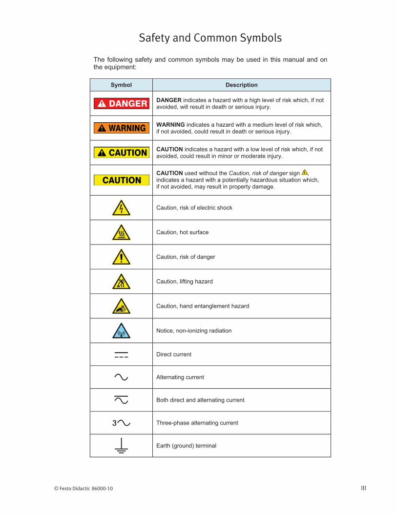
The following safety and common symbols may be used in this manual and on the equipment:
Symbol Description
DANGER indicates a hazard with a high level of risk which, if not avoided, will result in death or serious injury.
WARNING indicates a hazard with a medium level of risk which, if not avoided, could result in death or serious injury.
CAUTION indicates a hazard with a low level of risk which, if not avoided, could result in minor or moderate injury.
CAUTION used without the Caution, risk of danger sign , indicates a hazard with a potentially hazardous situation which, if not avoided, may result in property damage.
Caution, risk of electric shock
Caution, hot surface
Caution, risk of danger
Caution, lifting hazard
Caution, hand entanglement hazard
Notice, non-ionizing radiation
Direct current
Alternating current
Both direct and alternating current
Three-phase alternating current
Earth (ground) terminal

Safety and Common Symbols
IV © Festo Didactic 86000-10
Symbol Description
Protective conductor terminal
Frame or chassis terminal
Equipotentiality
On (supply)
Off (supply)
Equipment protected throughout by double insulation or reinforced insulation
In position of a bi-stable push control
Out position of a bi-stable push control

© Festo Didactic 86000-10 V
Table of Contents
Preface ................................................................................................................. VII
About This Manual ................................................................................................ XI
To the Instructor .................................................................................................. XIII
Exercise 1 Pressure Switch ............................................................. 1
Exercise 2 Float Switch .................................................................. 17
Exercise 3 Vibrating Level Switch ................................................. 29
Exercise 4 Conductivity Level Switch .......................................... 43
Appendix A Conversion Table ......................................................... 57
Appendix B Pressure Switch Functions ......................................... 59
Appendix C Pressure Switch Errors and Warnings ...................... 61
Appendix D Pressure Switch Faults ............................................... 63
Appendix E Float Switch Faults ...................................................... 65
Appendix F Vibrating Level Switch Faults ..................................... 67
Appendix G Conductivity Level Switch Faults ............................... 69
Index .................................................................................................................... 71
Bibliography ......................................................................................................... 73


© Festo Didactic 86000-10 VII
Preface
Automated process control offers so many advantages over manual control that the majority of today’s industrial processes use it to some extent. Breweries, wastewater treatment plants, mining facilities, and the automotive industry are just a few industries that benefit from automated process control systems.
Maintaining process variables such as pressure, flow, level, temperature, and pH within a desired operating range is of the utmost importance when manufacturing products with a predictable composition and quality.
The Instrumentation and Process Control Training System, series 353X, is a state-of-the-art system that faithfully reproduces an industrial environment. Throughout this course, students develop skills in the installation and operation of equipment used in the process control field. The use of modern, industrial-grade equipment is instrumental in teaching theoretical and hands-on knowledge required to work in the process control industry.
The modularity of the system allows the instructor to select the equipment required to meet the objectives of a specific course. Two mobile workstations, on which all of the equipment is installed, form the basis of the system. Several optional components used in pressure, flow, level, temperature, and pH control loops are available, as well as various valves, calibration equipment, and software. These add-ons can replace basic components having the same functionality, depending on the context. During control exercises, a variety of controllers can be used interchangeably depending on the instructor’s preference.
We hope that your learning experience with the Instrumentation and Process Control Training System will be the first step toward a successful career in the process control industry.

Preface
VIII © Festo Didactic 86000-10

Preface
© Festo Didactic 86000-10 IX
We invite readers of this manual to send us their tips, feedback, and suggestions for improving the book.
Please send these to [email protected].
The authors and Festo Didactic look forward to your comments.

© Festo Didactic 86000-10 XI
About This Manual
Safety considerations
Safety symbols that may be used in this manual and on the equipment are listed in the Safety Symbols table at the beginning of the manual.
Safety procedures related to the tasks that you will be asked to perform are indicated in each exercise.
Make sure that you are wearing appropriate protective equipment when performing the tasks. You should never perform a task if you have any reason to think that a manipulation could be dangerous for you or your teammates.
Systems of units
Units are expressed using the International System of Units (SI) followed by the units expressed in the U.S. customary system of units (between parentheses).


© Festo Didactic 86000-10 XIII
To the Instructor
You will find in this Instructor Guide all the elements included in the Student Manual together with the answers to all questions, results of measurements, graphs, explanations, suggestions, and, in some cases, instructions to help you guide the students through their learning process. All the information that applies to you is placed between markers and appears in red.
Accuracy of measurements
The numerical results of the hands-on exercises may differ from one student to another. For this reason, the results and answers given in this manual should be considered as a guide. Students who correctly performed the exercises should expect to demonstrate the principles involved and make observations and measurements similar to those given as answers.

Sample Exercise
Extracted from
the Student Manual
and the Instructor Guide

© Festo Didactic 86000-10 29
Learn the working principle of vibrating level switches and learn how to use the vibrating level switch, Model 46933.
The Discussion of this exercise covers the following points:
Introduction How a tuning fork works Industrial applications
Introduction
Among the vast quantity of point-level detection devices, vibrating level switches distinguish themselves by their ability to detect the level of almost anything from liquids to solids. There are three main types of vibrating level switches: tuning fork, vibrating-reed level switch, and vibrating probe. Although the shape and working principles of these three types of switches differ slightly, they all induce a vibration in their probe and detect the change in the oscillation frequency when the probe is covered by the process material.
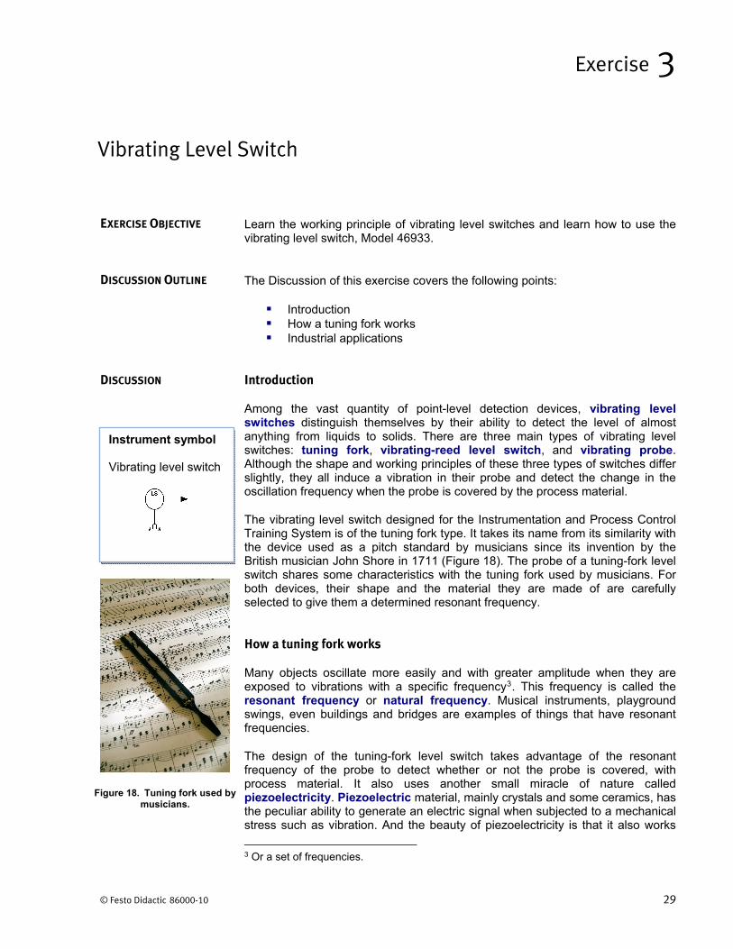
The vibrating level switch designed for the Instrumentation and Process Control Training System is of the tuning fork type. It takes its name from its similarity with the device used as a pitch standard by musicians since its invention by the British musician John Shore in 1711 (Figure 18). The probe of a tuning-fork level switch shares some characteristics with the tuning fork used by musicians. For both devices, their shape and the material they are made of are carefully selected to give them a determined resonant frequency.
How a tuning fork works
Many objects oscillate more easily and with greater amplitude when they are exposed to vibrations with a specific frequency3. This frequency is called the resonant frequency or natural frequency. Musical instruments, playground swings, even buildings and bridges are examples of things that have resonant frequencies.
The design of the tuning-fork level switch takes advantage of the resonant frequency of the probe to detect whether or not the probe is covered, with process material. It also uses another small miracle of nature called piezoelectricity. Piezoelectric material, mainly crystals and some ceramics, has the peculiar ability to generate an electric signal when subjected to a mechanical stress such as vibration. And the beauty of piezoelectricity is that it also works
3 Or a set of frequencies.
Vibrating Level Switch
Exercise 3
EXERCISE OBJECTIVE
DISCUSSION OUTLINE
DISCUSSION
Instrument symbol Vibrating level switch
Figure 18. Tuning fork used by musicians.
Exercise 3 – Vibrating Level Switch Discussion
30 © Festo Didactic 86000-10
the other way around. That is, if an electric signal is applied to a piezoelectric material, it responds by vibrating at its resonant frequency.
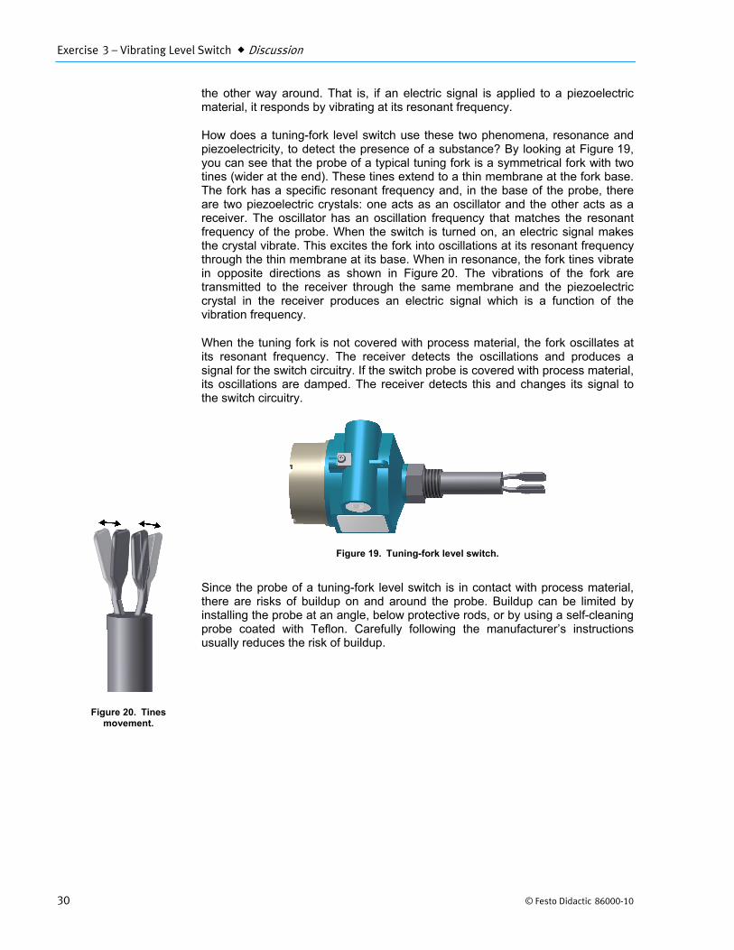
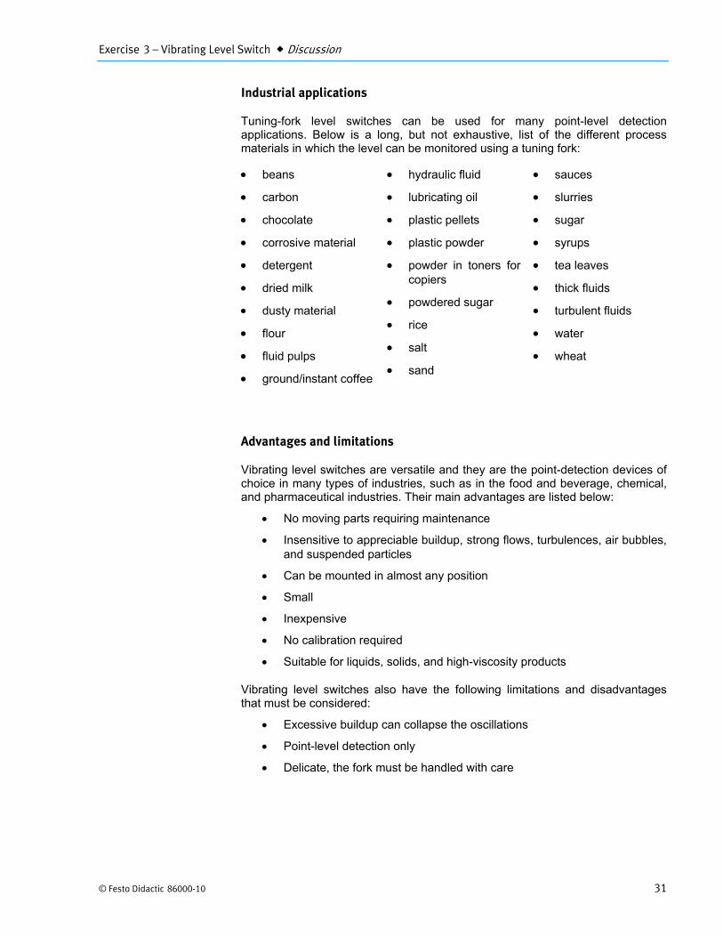
How does a tuning-fork level switch use these two phenomena, resonance and piezoelectricity, to detect the presence of a substance? By looking at Figure 19, you can see that the probe of a typical tuning fork is a symmetrical fork with two tines (wider at the end). These tines extend to a thin membrane at the fork base. The fork has a specific resonant frequency and, in the base of the probe, there are two piezoelectric crystals: one acts as an oscillator and the other acts as a receiver. The oscillator has an oscillation frequency that matches the resonant frequency of the probe. When the switch is turned on, an electric signal makes the crystal vibrate. This excites the fork into oscillations at its resonant frequency through the thin membrane at its base. When in resonance, the fork tines vibrate in opposite directions as shown in Figure 20. The vibrations of the fork are transmitted to the receiver through the same membrane and the piezoelectric crystal in the receiver produces an electric signal which is a function of the vibration frequency.
When the tuning fork is not covered with process material, the fork oscillates at its resonant frequency. The receiver detects the oscillations and produces a signal for the switch circuitry. If the switch probe is covered with process material, its oscillations are damped. The receiver detects this and changes its signal to the switch circuitry.
Figure 19. Tuning-fork level switch.
Since the probe of a tuning-fork level switch is in contact with process material, there are risks of buildup on and around the probe. Buildup can be limited by installing the probe at an angle, below protective rods, or by using a self-cleaning probe coated with Teflon. Carefully following the manufacturer’s instructions usually reduces the risk of buildup.
Figure 20. Tines movement.
Exercise 3 – Vibrating Level Switch Discussion
© Festo Didactic 86000-10 31
Industrial applications
Tuning-fork level switches can be used for many point-level detection applications. Below is a long, but not exhaustive, list of the different process materials in which the level can be monitored using a tuning fork:
beans
carbon
chocolate
corrosive material
detergent
dried milk
dusty material
flour
fluid pulps
ground/instant coffee
hydraulic fluid
lubricating oil
plastic pellets
plastic powder
powder in toners for copiers
powdered sugar
rice
salt
sand
sauces
slurries
sugar
syrups
tea leaves
thick fluids
turbulent fluids
water
wheat
Advantages and limitations
Vibrating level switches are versatile and they are the point-detection devices of choice in many types of industries, such as in the food and beverage, chemical, and pharmaceutical industries. Their main advantages are listed below:
No moving parts requiring maintenance
Insensitive to appreciable buildup, strong flows, turbulences, air bubbles, and suspended particles
Can be mounted in almost any position
Small
Inexpensive
No calibration required
Suitable for liquids, solids, and high-viscosity products
Vibrating level switches also have the following limitations and disadvantages that must be considered:
Excessive buildup can collapse the oscillations
Point-level detection only
Delicate, the fork must be handled with care
Exercise 3 – Vibrating Level Switch Discussion
32 © Festo Didactic 86000-10
Description of the supplied vibrating level switch
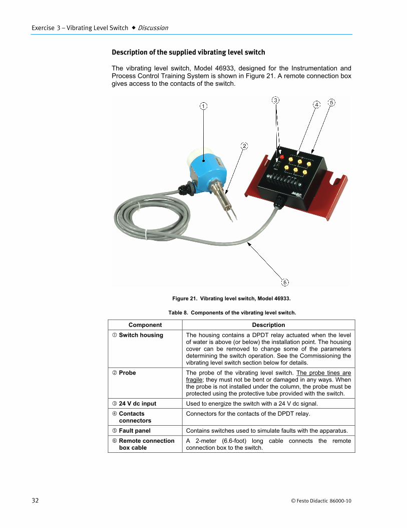
The vibrating level switch, Model 46933, designed for the Instrumentation and Process Control Training System is shown in Figure 21. A remote connection box gives access to the contacts of the switch.
Figure 21. Vibrating level switch, Model 46933.
Table 8. Components of the vibrating level switch.
Component Description
Switch housing The housing contains a DPDT relay actuated when the level of water is above (or below) the installation point. The housing cover can be removed to change some of the parameters determining the switch operation. See the Commissioning the vibrating level switch section below for details.
Probe The probe of the vibrating level switch. The probe tines are fragile; they must not be bent or damaged in any ways. When the probe is not installed under the column, the probe must be protected using the protective tube provided with the switch.
24 V dc input Used to energize the switch with a 24 V dc signal.
Contacts connectors
Connectors for the contacts of the DPDT relay.
Fault panel Contains switches used to simulate faults with the apparatus.
Remote connection box cable
A 2-meter (6.6-foot) long cable connects the remote connection box to the switch.

Exercise 3 – Vibrating Level Switch Discussion
© Festo Didactic 86000-10 33
Summary of technical specifications
Some technical specifications are summarized in this section. For details, please refer to the documentation provided with the device.
Device name Liquiphant M (FTL51)
Electronics FEL54
Measured variables Level (limit value)
Power supply 24 V dc
Relays DPDT (19 to 250 V ac or 19 to 55 V dc)
Temperature of the process -50°C to 150°C (-58°F to 300°F)
Maximum pressure 10000 kPa (1450 psi)
Maximum viscosity 10000 mm2/s (10000 cP)
Density Below 0.5 g/cm3 (0.5 SUG) or above 0.7 g/cm3 (0.7 SUG)
Installing the vibrating level switch
The probe tines are fragile; they must not be bent or damaged in any way. When the probe is not installed under the column, the probe must be protected using the protectivetube provided with the switch.
The vibrating level switch is designed to be installed at the bottom of the column. Use Figure 22 and the instructions below to install the vibrating level switch on your system.
a. Use a wrench to remove the brass hexagonal-head plug under the column.
b. Remove the protective tube from the switch probe.
c. Insert the switch probe in the hole at the bottom of the column and screw it in place using a wrench. If required, use Teflon tape for water tightness.

Exercise 3 – Vibrating Level Switch Discussion
34 © Festo Didactic 86000-10
Figure 22. Installing the vibrating level limit switch.
Do not use the switch housing to screw the probe in place. This will damage the wiring inside the switch. Use a wrench instead.
Make sure the housing cover is in place before using the switch. Without the housingcover, there are risks that water comes in contact with electrical components.
Commissioning the vibrating level switch
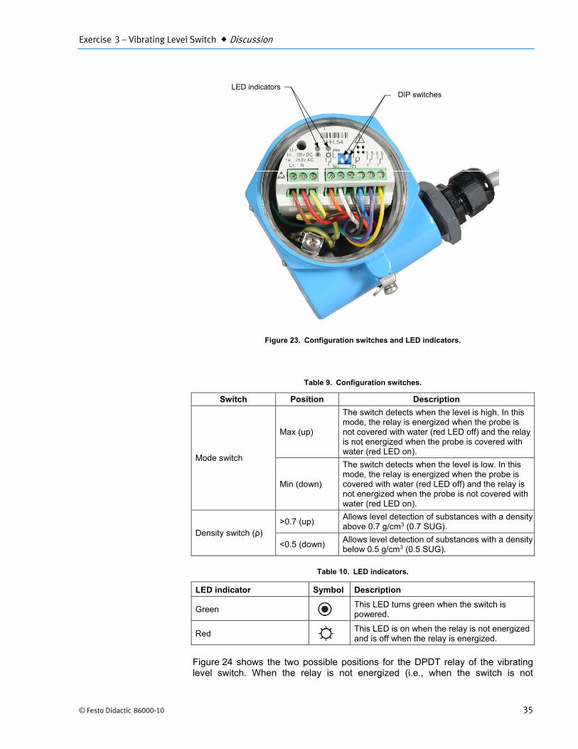
Removing the switch cover gives access to two configuration switches and two LED indicators. Figure 23 shows the inside of the vibrating level switch, Model 46933. The two LED indicators shown on the figure give the status of the switch. The first DIP switch allows setting the switch operation mode to maximum level detection or minimum level detection, while the second switch allows setting the density of the measured process material. Table 9 details the different configurations available and Table 10 lists what the LED indicators represent in terms of the switch status.
Exercise 3 – Vibrating Level Switch Discussion
© Festo Didactic 86000-10 35
Figure 23. Configuration switches and LED indicators.
Table 9. Configuration switches.
Switch Position Description
Mode switch
Max (up)
The switch detects when the level is high. In this mode, the relay is energized when the probe is not covered with water (red LED off) and the relay is not energized when the probe is covered with water (red LED on).
Min (down)
The switch detects when the level is low. In this mode, the relay is energized when the probe is covered with water (red LED off) and the relay is not energized when the probe is not covered with water (red LED on).
Density switch (ρ) >0.7 (up)
Allows level detection of substances with a density above 0.7 g/cm3 (0.7 SUG).
<0.5 (down) Allows level detection of substances with a density below 0.5 g/cm3 (0.5 SUG).
Table 10. LED indicators.
LED indicator Symbol Description
Green This LED turns green when the switch is powered.
Red
This LED is on when the relay is not energized and is off when the relay is energized.
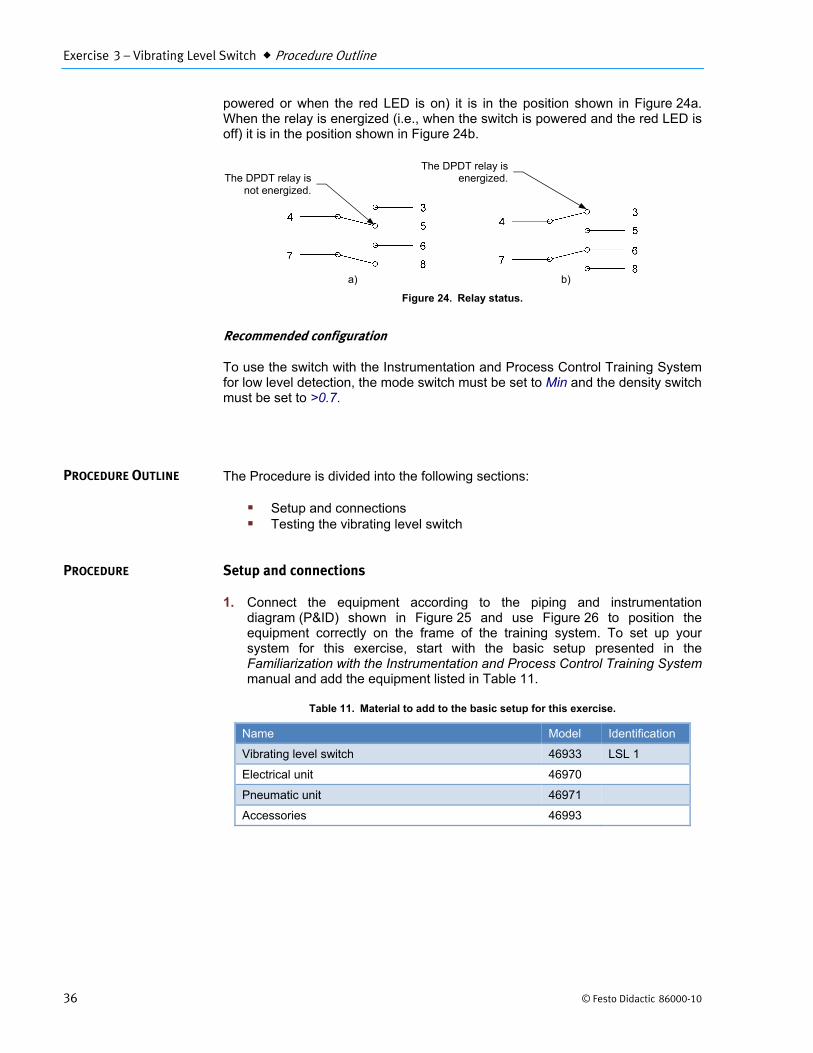
Figure 24 shows the two possible positions for the DPDT relay of the vibrating level switch. When the relay is not energized (i.e., when the switch is not
DIP switches LED indicators
Exercise 3 – Vibrating Level Switch Procedure Outline
36 © Festo Didactic 86000-10
powered or when the red LED is on) it is in the position shown in Figure 24a. When the relay is energized (i.e., when the switch is powered and the red LED is off) it is in the position shown in Figure 24b.
Figure 24. Relay status.
Recommended configuration
To use the switch with the Instrumentation and Process Control Training System for low level detection, the mode switch must be set to Min and the density switch must be set to >0.7.
The Procedure is divided into the following sections:
Setup and connections Testing the vibrating level switch
Setup and connections
1. Connect the equipment according to the piping and instrumentation diagram (P&ID) shown in Figure 25 and use Figure 26 to position the equipment correctly on the frame of the training system. To set up your system for this exercise, start with the basic setup presented in the Familiarization with the Instrumentation and Process Control Training System manual and add the equipment listed in Table 11.
Table 11. Material to add to the basic setup for this exercise.
Name Model Identification
Vibrating level switch 46933 LSL 1
Electrical unit 46970
Pneumatic unit 46971
Accessories 46993
PROCEDURE OUTLINE
PROCEDURE
a) b)
The DPDT relay isnot energized.
The DPDT relay isenergized.

Exercise 3 – Vibrating Level Switch Procedure
© Festo Didactic 86000-10 37
Figure 25. P&ID.

Exercise 3 – Vibrating Level Switch Procedure
38 © Festo Didactic 86000-10
Figure 26. Setup.
2. In this exercise, the vibrating level switch is used to close the solenoid valve if the level of water in the column is too low. Water exits the column only via the solenoid valve and the level of water in the column can rise again only when the solenoid valve is closed. This setup simulates a system that prevents the level of process material from being too low in a vessel.
3. Connect the control valve to the pneumatic unit. Details about the installation and operation of the control valve are available in the Familiarization with the Instrumentation and Process Control Training System manual.
4. Connect the pneumatic unit to a dry-air source with an output pressure of at least 700 kPa (100 psi).
Air from the pneumatic unit(140 kPa (20 psi))

Exercise 3 – Vibrating Level Switch Procedure
© Festo Didactic 86000-10 39
5. Wire the emergency push-button so that you can cut power in case of emergency. The Familiarization with the Instrumentation and Process Control Training System manual covers the security issues related to the use of electricity with the system as well as the wiring of the emergency push-button.
6. Do not power up the instrumentation workstation yet. Do not turn the electrical panel on before your instructor has validated your setup—that is, not before step 11.
7. Wire the vibrating level switch and the solenoid valve so that a voltage of 24 V dc actuates the solenoid valve when the level of water in the column is above the switch probe.
8. Connect the vibrating level switch to a 24 V dc power outlet on the electrical unit. Use one of the direct outputs to keep the switch from shutting off in case the emergency push-button or the OFF button (S2) is used.
9. Before proceeding further, complete the following checklist to make sure you have set up the system properly. The points on this checklist are crucial elements to the proper completion of this exercise. This checklist is not exhaustive, so be sure to follow the instructions in the Familiarization with the Instrumentation and Process Control Training System manual as well.
f
All unused male adapters on the column are capped and the flange is properly tightened.
The ball valves are in the positions shown in the P&ID.
The three-way valve at the suction of the pump (HV1) is set so that the flow is directed toward the pump inlet.
The control valve is fully open.
The pneumatic connections are correct.
The solenoid valve is wired so that the valve opens when the level of water in the column is above the switch probe.
The vent tube is correctly installed.
10. Ask your instructor to check and approve your setup.
11. Make sure it is safe to energize the system for you and for the team working on the other side of the system, if any. When ready, turn on the main power.
Testing the vibrating level switch
12. Press the S1 button to power all the devices not already active on the station (i.e., the drive, the pneumatic devices, etc.).

Exercise 3 – Vibrating Level Switch Conclusion
40 © Festo Didactic 86000-10
13. Test your system for leaks. Use the drive to make the pump run at low speed to produce a small flow rate. Gradually increase the flow rate, up to 50% of the maximum flow rate that the pumping unit can deliver (i.e., set the drive speed to 30 Hz). Repair any leaks.
14. Stop the drive and let the column drain.
15. Start the pump and fill the column up to about 25 cm (10 in).
16. Using HV2, set the flow rate at about 24 L/min (6 gal/min) so that the level in the column decreases slowly.
17. Watch the level decrease in the column.
18. What happens when the level drops below the probe tines?
The oscillation frequency of the tuning fork changes and the switch changes the state of its relay. This closes the solenoid valve and the level in the column starts to increase again. Once the level is higher than the switch probe, the oscillation frequency of the tuning fork changes again, the solenoid valve opens, and the level starts to decrease again.
19. Is this a good way to control the level in a vessel? Why?
No. The vibrating level switch can only provide on-off control for a specific level. Moreover, the switch will probably turn on and off continuously as the level oscillates around the set point, which can cause the switch and the devices connected to the switch to wear out prematurely.
20. Stop the pump, open HV4, and turn off the power to the system.
You should now be able to install and use the vibrating level switch, Model 46933. You should also be able to change the switch configuration.
1. Name three types of vibrating level switches.
Tuning fork, vibrating reed level switch, and vibrating probe.
CONCLUSION
REVIEW QUESTIONS
Exercise 3 – Vibrating Level Switch Review Questions
© Festo Didactic 86000-10 41
2. What is the resonant frequency of an object?
The frequency at which the object oscillates more easily and with greater amplitude
3. What is piezoelectricity?
Piezoelectricity is the ability of some materials to generate an electric signal when subjected to a mechanical stress and to respond to an electric signal by vibrating at their resonant frequency.
4. Describe how a tuning fork level switch works.
When the tuning fork is not covered with process material, the fork oscillates at its resonant frequency. The receiver detects the oscillations and produces a signal for the switch circuitry. If the switch probe is covered with process material, its oscillations are damped and the receiver detects it and changes its signal to the switch circuitry.
5. Name three advantages and three limitations of vibrating level switches.
Advantages • No moving parts requiring maintenance • Insensitive to appreciable buildup, strong flows, turbulences, air bubbles, and suspended particles • Can be mounted in almost any position • Small • Inexpensive • No calibration required • Suitable for liquids, solids, and high-viscosity products Limitations • Excessive buildup can collapse the oscillations • Point-level detection only • Delicate, the fork must be handled with care

© Festo Didactic 86000-10 73
Bibliography
Benson, Harris, University Physics, New York, John Wiley & Sons, 1996, ISBN 0-471-00689-0.
Lipták, Béla G., Instrument Engineers' Handbook, Volume 1: Process Measurement and Analysis, Fourth Edition, CRC Press, 1999, ISBN 0-8019-8197-2.