process control fundamentals chemical engineering dept ... · absorption the removal of one or ......
TRANSCRIPT

1
Part (1)
Generally, if the absorption factor A = L/mV is greater than 1 for a component, then any degree
of separation can be achieved. The larger A is the fewer stages (or trays) are required to
achieve a given level of separation, although the absorbent flow rate may become too large.
Absorption The removal of one or more selected components (absorbate) from a mixture of gases by absorption into a suitable liquid (absorbent) through a gas-liquid interface. Stripping Reverse of absorption.
Liquid Out
A= 15 mole
Gas In
Pure Liquid In
A= 0 mole
Gas Out A= 5 mole
A= 20 mole

2
Gas Treating in Major Industrial Processes
3
Liquid in
Vapor in
Vapor out
Liquid out
1
2
N–1
N
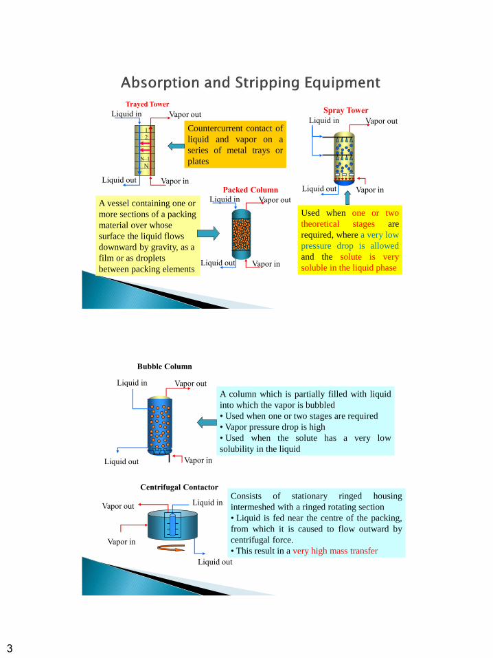
Trayed Tower
Liquid in
Vapor in
Vapor out
Liquid out
Spray Tower
Liquid in
Vapor in
Vapor out
Liquid out
Packed Column
Countercurrent contact of
liquid and vapor on a
series of metal trays or
plates
A vessel containing one or
more sections of a packing
material over whose
surface the liquid flows
downward by gravity, as a
film or as droplets
between packing elements
Used when one or two
theoretical stages are
required, where a very low
pressure drop is allowed
and the solute is very
soluble in the liquid phase
Liquid in Vapor out
Vapor in
Liquid out
Centrifugal Contactor
Liquid in
Vapor in
Vapor out
Bubble Column
Liquid out
A column which is partially filled with liquid
into which the vapor is bubbled
• Used when one or two stages are required
• Vapor pressure drop is high
• Used when the solute has a very low
solubility in the liquid
Consists of stationary ringed housing
intermeshed with a ringed rotating section
• Liquid is fed near the centre of the packing,
from which it is caused to flow outward by
centrifugal force.
• This result in a very high mass transfer

4
Liquid in
Vapor in
Vapor out
Liquid out
1
2
N–1
N
Trayed Tower
The function of a tray is to facilitate contact
between the vapour phase and liquid phase so
that mass transfer between the 2 phases can
take place.
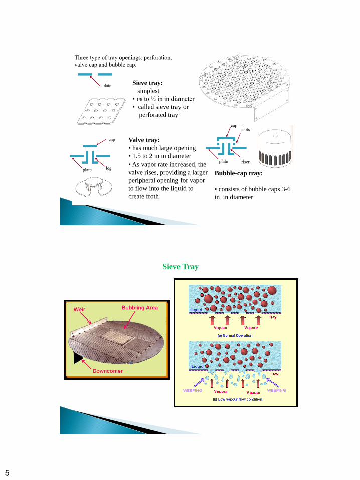
Weir
Plate
Foam
Phase Contact on a Contacting Tray
Each tray can be considered as being made
up of 3 sections: weir, bubbling area, and
downcomer.
The bubbling area is the place where vapour-
liquid contact takes place.
The function of a weir is to maintain a
desired liquid level on the tray.
Downcomers are used to guide liquid flow
from an upper tray to a lower tray.
5
slots cap
riser plate
plate
cap
leg
plate
Three type of tray openings: perforation,
valve cap and bubble cap.
Sieve tray:
simplest
• 1/8 to ½ in in diameter
• called sieve tray or
perforated tray
Valve tray:
• has much large opening
• 1.5 to 2 in in diameter
• As vapor rate increased, the
valve rises, providing a larger
peripheral opening for vapor
to flow into the liquid to
create froth
Bubble-cap tray:
• consists of bubble caps 3-6
in in diameter
Sieve Tray

6
Bubble-Cap Tray
The bubble-cap consists of a slotted cap on a central riser.
Valve Tray
A valve tray is a flat perforated plate, with each
perforation fitted with a movable disk (the
"valve").

7
Flow weeps through
the holes at low vapor
velocity
Weeping
Liquid cannot get
down the column
at high vapor velocity
Flooding

8
Used for continuous countercurrent
contacting of gas and liquid in absorption
as well as vapor-liquid contacting in
distillation
Consists of:
1. Cylindrical column
2. Distributing space at the bottom
3. Distributing device at the top
4. Gas outlet at the top
5. Liquid outlet at the bottom
6. Packing material
Operation:
Why packing? To provide large area of intimate contact between liquid and gas
Gas enters the distributing space at the
bottom below the packed section and rises
upward to contact the descending liquid
Clean gas out
Dirty gas in
Mist Eliminator
Liquid Sprays
Packing
Liquid outlet

9
Packing Materials
Random packings are dumped into a column
during installation and allowed to fall in
random
Various types of packings made of different types of materials of construction are
available, and both random and structured packings are commonly used
Structured packings are considerably more
expensive per unit volume than random
packings. They come with different sizes and
are neatly stacked in the column. Structure
packings usually offer less pressure drop and
have higher efficiency and capacity than
random packings.
Packing Materials
Many of them are available, but most common ones are used in the industry
(a) Raschig ring (b) Berl saddle
(c) Pall ring (d) Intalox metal Jaeger metal Tri-Pack
Older types and seldom used Second generation
Made of plastic or metal
Void space 0.9-0.96
Area 100-200 m2/m3
Third generation
Combination of Pall ring and Berl saddle
Porosity: 0.95-0.98
Only slightly more efficient than Pall ring
Commercial packing are available in sizes of 3 – 75 mm
Mostly made of clay, porcelain, metal, or plastic.
Packing should have the following properties:
should be inert must be strong should provide good contact
high porosity to avoid high pressure drop low cost
10
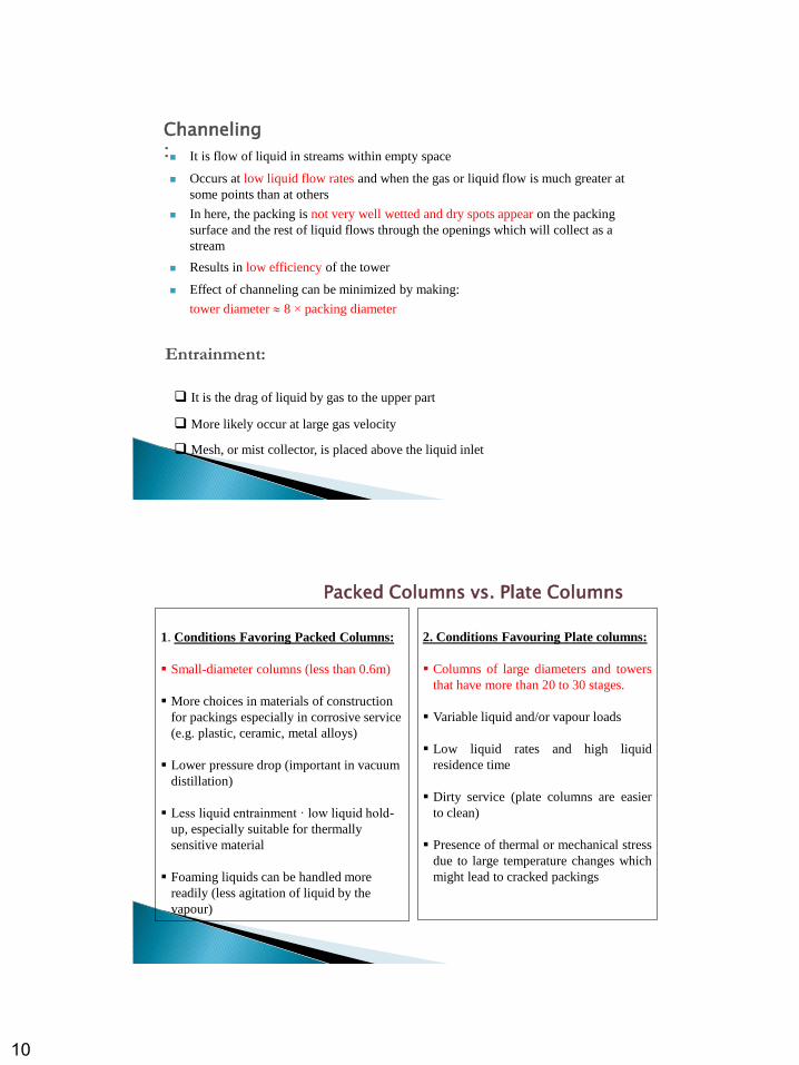
Channeling: It is flow of liquid in streams within empty space
Occurs at low liquid flow rates and when the gas or liquid flow is much greater at
some points than at others
In here, the packing is not very well wetted and dry spots appear on the packing
surface and the rest of liquid flows through the openings which will collect as a
stream
Results in low efficiency of the tower
Effect of channeling can be minimized by making:
tower diameter 8 × packing diameter
Entrainment:
It is the drag of liquid by gas to the upper part
More likely occur at large gas velocity
Mesh, or mist collector, is placed above the liquid inlet
Packed Columns vs. Plate Columns
1. Conditions Favoring Packed Columns:
Small-diameter columns (less than 0.6m)
More choices in materials of construction
for packings especially in corrosive service
(e.g. plastic, ceramic, metal alloys)
Lower pressure drop (important in vacuum
distillation)
Less liquid entrainment · low liquid hold-
up, especially suitable for thermally
sensitive material
Foaming liquids can be handled more
readily (less agitation of liquid by the
vapour)
2. Conditions Favouring Plate columns:
Columns of large diameters and towers
that have more than 20 to 30 stages.
Variable liquid and/or vapour loads
Low liquid rates and high liquid
residence time
Dirty service (plate columns are easier
to clean)
Presence of thermal or mechanical stress
due to large temperature changes which
might lead to cracked packings

11
Columns Process Design: Four Basic Principles Extent of separation
# of equilibrium stages, predicted with high confidence
Graphical methods
Approximate methods - Kremser equation
Rigorous methods - computer simulation
Time of phase contact
Rate = (Driving force)/Resistance
Driving force = departure from equilibrium
Resistance (difficult to predict)
operating conditions: T, P, composition
physical properties of both phases
velocity, flow regime
Columns Process Design: Four Basic Principles
Permissible pressure drop
Fixes diameter of column
Energy requirements
Heat
producing temperature changes
creating a new phase
overcoming heat of solution effects
Mechanical/Electrical
moving fluids from one location to another
dispersing liquids and gases
operate moving parts of machinery
12
1. Entering gas or liquid flow rate, composition, temperature and pressure
2. Degree of separation desired
3. Choice of absorbent (or stripping) agent
4. Operating pressure and temperature and allowable pressure drop
5. Minimum absorbent (or stripping) flow rate
6. Number of equilibrium stages
7. Heat effects and need for cooling
8. Type of absorber (stripper) equipment
9. Height of absorber (stripper)
10. Diameter of absorber (stripper)
General Design Considerations …
For an absorber (in general)
Operating pressure should be high and temperature low
to minimize stage requirements and/or absorbent flow rate and
to lower the equipment volume required to accommodate the gas flow.
However:
both compression and refrigeration of a gas are expensive.
Then:
the most absorbers are operated at feed-gas pressure, which may be greater
than ambient pressure and ambient temperature.
which can be achieved by cooling the feed gas and absorbent with cooling
water, unless one or both streams already exists at a sub-ambient temperature.

13
General Design Considerations …
For a stripper (in general)
Operating pressure should be low and temperature high
to minimize stage requirements and/or stripper agent flow rate.
However:
Maintenance of a vacuum is expensive.
Then:
Commonly stripper are operated at a pressure just above ambient pressure
and ambient temperature
A high temperature can be used, but it should be not so high as to cause
undesirable chemical reactions.
Operating temperature and pressure must be compatible with the
necessary phase conditions of the streams being contacted.
Flooding velocity: it the upper limit of the gas flow where the liquid flows over at a given
flow of liquid
At normal conditions, with low gas velocity, the liquid flows downward through the
packing without influencing the upward gas flow.
Loading point: it is the gas flow rate when the gas starts to hinder the liquid downflow
Above this limit, tower is not functioning
local accumulation or pools of liquid start to appear in the packing
Pressure drop of the gas starts to rise at a faster rate
At the loading point, the liquid can no longer flow down through the packing and is
blown out with the gas
In actual operation: gas velocity is well below flooding, half flooding velocity
Loading: the liquid flow is reduced due to the increased gas flow; liquid is held in the
void space between packing
Flooding: the liquid stops flowing altogether and collects in the top of the column due to
very high gas flow