proceedings of vol. no. may ion laser plasmas
TRANSCRIPT
724 PROCEEDINGS OF THE IEEE, VOL. 59, NO. 5 , MAY 1971
Ion Laser Plasmas WILLIAM B. BRIDGES, FELLOW, IEEE, ARTHUR N. CHESTER, MEMBER, IEEE,
A. STEVENS HALSTED, MEMBER, IEEE, AND JERALD V. PARKER, MEMBER, IEEE
Invited Paper
Abstract-The typical noble gas ion laser plasma consists of a high-current-density glow discharge in a noble gas, in the presence of a magnetic field. Typical CW plasma conditions are current densities of 100 to 2000 A/cm2, tube diameters of 1 to 10 mm, filling pressures of 0.1 to 1.0 torr, and an axial magnetic field of the order of lo00 0. Under these conditions the typical fractional ionization is about 2 percent and the electron temperature between 2 and 4 eV. Pulsed ion lasers typically use higher current densities and lower operating pressures.
This paper discusses the properties of ion laser plasmas, in terms of both their external discharge parameters and their internal ion and excited state densities. The effect these proporties have on laser op- eration is explained. Many interesting plasma effects, which are im- portant in ion lasers, are given attention. Among these are discharge nonuniformity near tube constrictions, extremely high ion radial drift velocities, wall losses intermediate between ambipolar diffusion and free fall, gas pumping effects, and radiation trapping. The current status of ion laser technology is briefly reviewed.
T I. INTRODUCTION
HE ION LASER is one of the most important prac- tical sources of visible and ultraviolet coherent light presently known. In addition, it incorporates a gaseous
plasma exhibiting a number of interesting properties besides laser action. This paper briefly reviews some of the principal characteristics of ion laser plasmas.
Section I summarizes the operating principles and output Characteristics of the most important ion lasers. Section I1 presents a basic description of the CW argon ion laser plasma as an example, covering mainly those aspects that are reasonably well understood at present. Section I11 discusses some of the important plasma phenomena which also occur in ion laser plasmas but which are understood only qualitatively. This discussion includes both technologi- cal problems and their underlying physical effects.
A . Characteristics of Ion Lasers
An ion laser plasma generally consists of a long narrow cylindrical highdensity glow discharge. The optical radia- tion from the discharge is directed repeatedly through the glow region by mirrors placed at each end of the tube. The positive column of the discharge plasma constitutes the laser medium and amplifies the radiation. Many different excitation techniques have been used to produce a glow discharge of the proper characteristics. Among these are pulsed and CW dc discharges using electrodes (both hot and
Manuscript received January 16, 1971. This invited paper is one of a
W. B. Bridges, A. N. Chester, and J. V. Parker are with the Hughes
A. S. Halsted is with the Electron Dynamics Division, Hughes Aircraft
series planned on topics of general interest-The Editor.
Research Laboratories, Malibu, Calif. 90265.
Company, Torrance, Calif. 90509.
cold cathode), pulsed dc discharges using electrodeless magnetic induction coupling, pulsed and CW RF discharges using induction coupling with electric fields both longitudi- nal and transverse to the long dimension of the plasma, microwave cyclotron resonance discharges, beam-generated plasmas, and pinch-generated plasmas (both z- and &pinch types). In this brief review it would be impossible to cover the detailed characteristics produced by each excitation method. Representative examples must necessarily be chosen. It is fortunate, however, that the method of produc- ing the plasma seems to have little effect on the laser prop erties; CW ion lasers exhibit roughly the same overall characteristics whether produced by a hot cathode dc dis- charge or an RF induction excited system. Pulsed lasers are likewise relatively independent of the excitation means. In much of the discussion following, the argon ion laser [l I- [3] will be taken as the example, since the largest body of information exists for this most popular laser type.
For a typical ion laser the most important physical processes producing the laser action are as follows. In the glow discharge, approximately 1 percent of the atoms are ionized. Electrons with a mean energy of 2 to 4 eV collide with ground state ions and produce excited ions, including ionic states that constitute the upper and lower laser levels. The excitation cross sections and radiative lifetimes are such that the steady-state population density of the upper laser levels in the discharge is much larger than the density of the lower laser levels. This population inversion produces optical gain and laser action, typically on radiative transi- tions between several pairs of upper and lower levels. The laser output wavelengths depend on the choice of gas, the operating conditions, or the use of wavelength-selective laser mirrors.
The great practical importance of ion lasers derives from several useful characteristics. The optical gain of the ion laser plasma is very high, typically > 1 dB/m (23 percent/m) [3]-[7] and as high as 13 dB/m in argon [8]; this makes it very easy to secure laser oscillation even when mirrors and windows are not of the highest optical quality. In addi- tion, ion lasers produce numerous laser lines that lie in or near the visible portion of the spectrum; at present, 437 different wavelengths have been observed, originating from 29 different elements, and ranging in wavelength from 0.2358 to 1.555 pm [9]. Finally, the most important laser lines (and more than half of all observed lines) employ only noble &es in the discharge tube, and the chemical inertness of these gases simplifies many aspects of tube technology.
BRIDGES et al. : ION LASER PLASMAS 125
TABLE I OPERATING CONDITIONS OF TYPICAL ION LASERS
Tube Tube Diameter Length Discharge
Type of Laser (mm) (cm) Current (A) Gas Fill Pressure
Pulsed, noble 2-10 10-200 100-1OOO 10-50mtorr ~ ~ ~ ~~~~
gas
CW, noble gas 1-12 10-50 10-100 50-1000 mtorr
CW, He-Cd 3 150 0.040.10 2-10 mtorr Cd plus 2-8 torr He
The operating conditions of the most useful ion lasers are summarized in Table 1. The simplest type of ion laser is that operated with a low-dutycycle pulsed discharge, generally with pulses 1-100 ,us in duration and repetition rates up to a few hundred pulses per second. A typical pulsed tube consists of a long glass, quartz, or ceramic capillary with an anode and a cold cathode located in side- arms at each end of the tube. An external optical resonator is usually employed, with Brewster’s angle windows mounted on the discharge tube to minimize reflective loss. The laser output generally follows the current pulse. How- ever, if the current density and the pulse length become too great, laser action may be quenched by loss of gas density in the capillary (caused by thermal driveout and gas pumping effects) or by radiation trapping of the lower laser level, as discussed later. In addition, at long pulse lengths the capillary may be thermally destroyed unless adequately cooled.
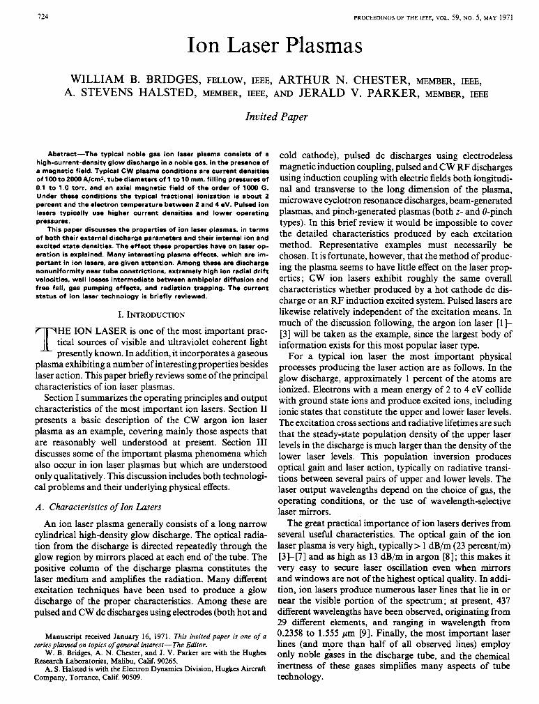
The second type of ion laser listed in Table I is the CW noble gas ion laser. The earliest CW ion lasers used a water- cooled quartz capillary to permit high average input power to the discharge. Gas pumping caused by electron and ion drift motion in the positive column led to substantial pressure gradients along the tube. To keep the discharge maintained at a convenient voltage it was found desirable to equalize the pressure at the cathode and anode by con- necting them with a gas return path, which consisted of a glass tube with sac i en t conductance to permit easy gas flow but long enough to prevent a discharge from striking through it. A photograph of such a tube appears in [lo]. The addition of a magnetic field (about 1 kG) with field lines parallel to the optical axis increases the laser output, particularly from tubes of less than 6-mm diameter, and a magnetic field is usually used with such tubes. The higher current densities and extended lifetime currently demanded of ion lasers have led to the development of highly engi- neered metal-ceramic tubes of the type shown in Fig. 1.
The third major type of ion laser, typified by the CW helium-cadmium laser, operates at modest power levels and does not require special cooling. The most popular version of this laser [ l l ] resembles in construction the familiar helium-neon lasers except for the addition of a sidearm containing cadmium metal. The vapor pressure of cadmium in the discharge is controlled by heating this sidearm. Both zinc and selenium ion lasers have.been made in this form to date (see tabulation and references in [9]).
Fig. 1 . A high-performance metal-ceramic argon ion laser discharge tube with its associated magnet. Metal cooling fins surround the ceramic section. (Hughes Electron Dynamics Division.)
The output characteristics of the most extensively studied practical ion lasers are summarized in Table 11. The argon ion laser, with blue and green output, has undergone the most advanced development to date. The newest among the sources listed is the xenon IV laser,’ which demonstrates a high-power pulsed mode of operation that is, so far, unique among ion lasers. The high electrical efficiencies (exceeding 0.1 percent) and the availability of multiwatt output at a great variety of wavelengths (of which only a few are listed here) make ion lasers important sources of coherent radia- tion in the visible and near UV.
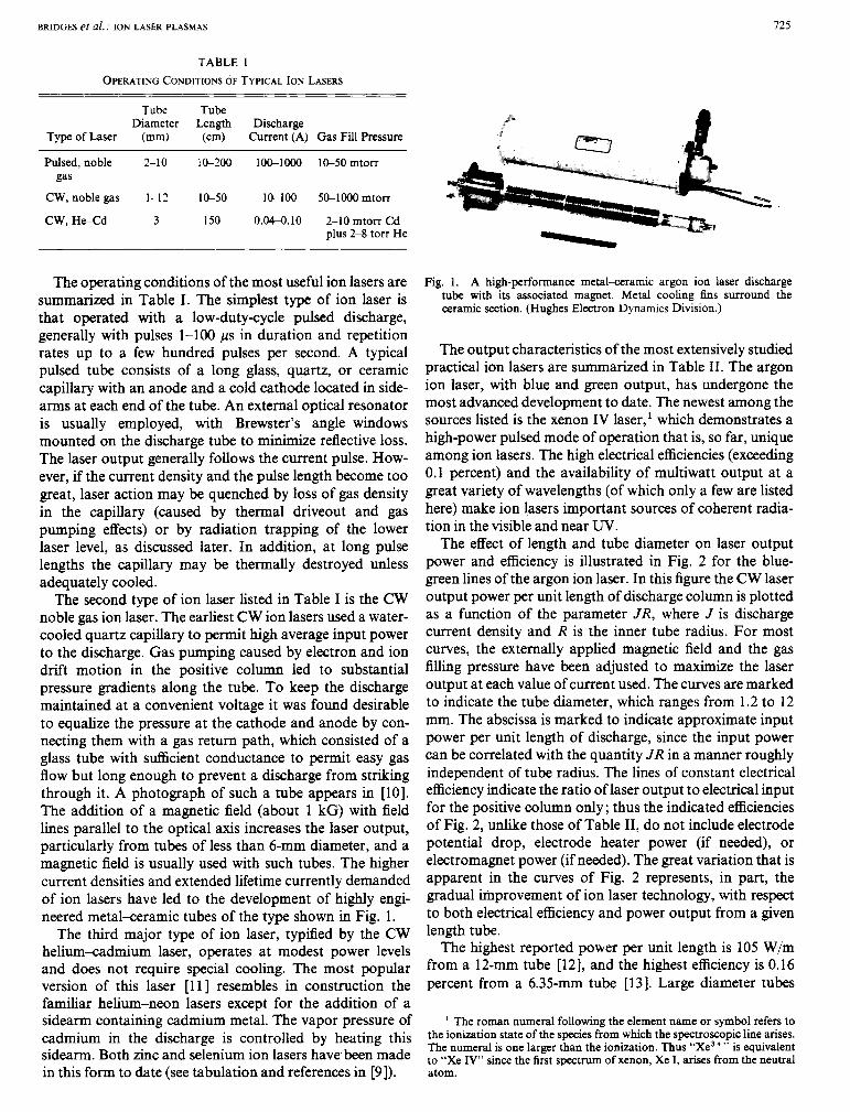
The effect of length and tube diameter on laser output power and efficiency is illustrated in Fig. 2 for the blue- green lines of the argon ion laser. In this figure the CW laser output power per unit length of discharge column is plotted as a function of the parameter JR, where J is discharge current density and R is the inner tube radius. For most curves, the externally applied magnetic field and the gas filling pressure have been adjusted to maximize the laser output at each value of current used. The curves are marked to indicate the tube diameter, which ranges from 1.2 to 12 mm. The abscissa is marked to indicate approximate input power per unit length of discharge, since the input power can be correlated with the quantity JR in a manner roughly independent of tube radius. The lines of constant electrical efficiency indicate the ratio of laser output to electrical input for the positive column only; thus the indicated efficiencies of Fig. 2, unlike those of Table 11, do not include electrode potential drop, electrode heater power (if needed), or electromagnet power (if needed). The great variation that is apparent in the curves of Fig. 2 represents, in part, the gradual improvement of ion laser technology, with respect to both electrical efficiency and power output from a given length tube.
The highest reported power per unit length is 105 W/m from a 12-mm tube [12], and the highest efficiency is 0.16 percent from a 6.35-mm tube [13]. Large diameter tubes
The roman numeral following the element name or symbol refers to the ionization state of the species from which the spectroscopic line arises. The numeral is one larger than the ionization. Thus “Xe3+” is equivalent to “Xe IV” since the &st s p e c t r u m of xenon, Xe I, arises from the neutral atom.
726
TABLE I1 ION LASER PERFORMANCE: 1970 STATE OF THE ART
PROCEEDINGS OF THE I E E E , MAY 1971
Output Power per Overall Electrical Lasing Species Lasing Mode Strongest Wavelengths (pm) Output Power Unit Length Efficiency (A)
Ar I I cw 0.4880, 0.5145 Kr I1 cw 0.6471 Cd I1 cw 0.4416 cd I1 cw 0.3250 AI 111 cw 0.3638, 0.351 1 Xe IV cw 0.4954-0.5395
Xe IV pulsed 0.5395, 0.5353, (5 lines)
0.5260
120 W' - 10 W' 0.2 we 0.02 W' 5 WL 0.5 Wh
105 W/mb 0.16' 5 W/m8 -0.01'** 0.14 W/me 0.09' 0.014 W/mc -0.01'J 5 W/m' 0.01' 1 W/mh <O.Olh
0.4 J/pulse' 0.14 J/m' (20 kW peak)
-0.3i.J
~
a K. Banse, H. Boersch, G. Herziger, G. Schafer, and W. Seelig, 2. Angew. Phvs.. vol. 26, 1969, pp. 195-200. ~ ~~
H. Boersch, J. Boscher, D. Hoder, and G. Schiifer, Phys. Left., vol. 31A, 1970, pp. 188-189. J. R. Fendley, Jr., Proc. 4th DOD Con$ Laser Technology (San Diego, Calif., Jan. 1970), vol. 1, pp. 391-398 (unpublished). W. B. Bridges and A. S . Halsted, Hughes Res. Labs., Malibu, Calif., Tech. Rep. AFAL-TR-67-89, May 1967 (unpublished); DDC accession no.
J. P. Goldsborough, Appl. Phys. Lett., vol. 15, 1969, pp. 159-161. W. T. Silfvast, Appl. Phys. L e t r . , vol. 13, 1968, pp. 169-171. The efficiency of 9.02 percent given in Silfvast is a misprint and should instead be 0.09
W. B. Bridges and G. N. Mercer, Hughes Res. Labs., Malibu, Calif., Rep. ECOM-0229-F, Oct. 1969 (unpublished); DDC accession no. AD-861-927.
AD-814897.
percent.
h - , "CW operation of high ionization states in a xenon laser," IEEEJ. Quantum E l w t r o m (Corresp.), vol. QE-5, Sept. 1969, pp. 47&477. ' W. W. Simmons, private communication, July 31, 1970. j Pulse efficiency is defined as peak laser output power, divided by the product of peak tube current and initial applied voltage. ' J. R. Fendley, Jr., private communication, Jan. 1970.
50
\ 3 E
I I- o W z
c_ IO J
z 3
E a a 5 W
b a
0.5
0.11 ' I I I J I I I I l l , , I I 1
5 IO 50 100 500 JR, A/cm
I I I I I I I I I I I I I 1 1 1 1 1 1 I I I
I 5 10 50 100 500 APPROXIMATE INPUT POWER, kW/m
Fig. 2. Summary of reported power output characteristics of CW Ax I1 ion l a s e r s from the following sources: Fig. 4 in [ 161; Fig. 1 in [53]; Fig. 13in[17];Fig.5in[54];Figs.10and14in[32];Fig.6in[]3];Fig.1in [12]; and Table I (4-mm by 18-in tube) in [ S I . Indicated electrical effi- ciency is calculated for positive column only, using axial electric field data from Fig. 32 in [17]; Figs. 4 and 14 in [32]; and eq. (3.1) in [26].
(- 10-12 mm) have some advantages-they require less or no external magnetic field for efficient operation; their larger wall area eases the thermal load on wall materials; and the larger optical beam size reduces the flux density .that must be withstood by optical components such as windows and mirrors. However, many applications require that the laser operate in a single transverse optical mode, so that the laser output is completely phase coherent across the beam front. This is very dif6cult to achieve in such a Iarger diameter tube [14] and limits the usefulness of this type of ion laser. An additional disadvantage of the larger bore tubes is that the laser gain and output power decrease with increasing tube diameter [ 6 ] , [17] ; thus many lines will not oscillate at all in a larger diameter tube, and those that will oscillate require higher quality windows and mirrors for efficient operation.
The relative merits of large and small diameter ion-laser tubes may be summarized as follows. When maximum power per unit length is desired on the strongest laser transitions (i.e., the Ar 11, Kr 11, and Xe IV lines of Table 11), the large diameter tubes are an appropriate choice. When minimum beam divergence (from single transverse mode operation), less output power (- 1 W), or other laser transitions are required, a small diameter tube is usually the best choice. When maximum overall electrical efficiency is required, the choice of tube geometry will depend upon the wavelengths desired and other operational require- ments.
Not surprisingly, the ranges of plasma characteristics that have been most fully explored correspond to the operating conditions of practical devices, as summarized in Tables I and I1 and in Fig. 2. We will proceed now to give a more complete description of what is known about the ion laser itself. Our discussion will center mainly on the most highly developed ion laser, the blue-green lines of Ar 11.
BRIDGES et al. : ION LASER PLASMAS 727
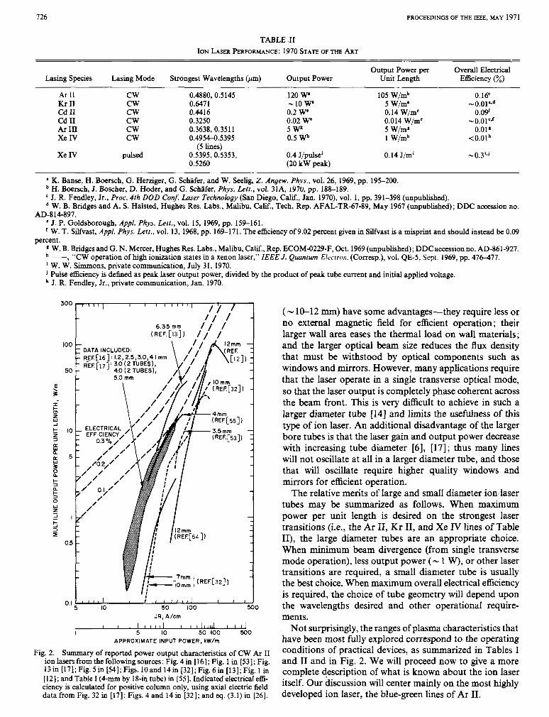
(4 (b) (4 ( 4 Fig. 3. Energy level diagrams for the blue and green transitions in Ar 11, showing various excitation schemes (from [17]).
B. Excitation Mechanisms of Ion h e r s The original model of laser excitation in noble gas ions
was proposed by Gordon et al. [15], [16], and is shown schematically in Fig. 3(a). In Gordon’s model, the upper laser level is excited by collisions between an electron and a ground state ion (process 2); the ion was presumably pro- duced by the collision of an electron and a neutral atom in the ground state (process 1). Radiative cascade from higher states and de-excitation of the upper laser level by electrons are neglected. The lower laser level is rapidly depopulated by radiation (in the vacuum W at ).x740 A for the 4s states of Ar 11). This depopulation is assumed to occur much more rapidly than any collisional electron excitation (dotted arrow). Finally, one assumes approximate charge neutrality in the plasma and current-independent electron tempera- ture. Then the upper laser level population N , turns out to vary as
N , a n p i w n,‘ a J 2 (1)
where ne, ni , and J are the electron density, ion density, and discharge current density, respectively. Such a quadratic current dependence has been observed in spontaneous emis- sion measurements over a wide range of gas pressures, cur- rents, and tube dimensions typical of CW ion lasers (see, for example, [17] and [18]). However, in pulsed operation, radiation trapping of the lower level population can upset the simple current dependence of (1). (See Section 111-C for a discussion of this effect.)
An alternate excitation method involving a single electron collision was proposed by Bennett et al. [3] and is shown in Fig. 3(b). This excitation process apparently occurs prin- cipally in low-pressure discharges excited by short pulses. A discharge with very high E / p is required to produce an elec- tron temperature sufficiently high to achieve a significant single step excitation rate. This mode of operation is also characterized by a unique distribution of spectral output. For example, under these conditions, 0.4765 pm is the strongest laser line in Ar 11. Such a spectral distribution is never observed in CW operation, where the 0.4880-pm and 0.5145-pm lines always dominate. Moreover, the single step excitation process (assuming constant electron tem- perature) would lead to a spontaneous emission rate from the upper laser level which varies linearly with discharge current, which is not observed in CW operation.
An additional excitation process was proposed by Labuda et al. [19], with ionic metastables serving as the intermediate species rather than the ion ground state, as shown in Fig. 3(c). Absorption measurements [19] show that these meta- stable levels are highly populated. The ionic metastables are produced either by electron collision with the ionic ground state lprocess 1 in Fig. 3(c)] or (more probably) by cascade from higher lying states (process 2) ; these higher lying states exhibit populations N,a J 2 , as shown by spon- taneous emission data. However, because the metastables are primarily destroyed by electron collisions rather than by spontaneous emission, it can be shown that the metastable population N , will be proportional to J rather than J 2 (see [16] or [17]). The upper laser level is then populated by yet another electron collision (process 3), and the relation N , cc J 2 obtains as before.
Our understanding of the upper level excitation processes remained essentially as described above until the measure- ments made by Rudko and Tang [20]. They found that a significant fraction of the upper laser level population was created by radiative cascade from higher lying states [see Fig. 3(d)]. By summing the spontaneous emission intensi- ties of all spectral lines terminating on a given upper laser level (for example, 4p 2D&2, the upper level of the 0.4880-pm transition), and then comparing this with the sum of in- tensities of those lines originating from that level we may determine the relative pumping rate due to cascade from the higher lying states. In a 1-mm-diameter tube operated without a magnetic field, Rudko and Tang found that approximately 50 percent of the 4p ,D!&, level population is created by cascade. Similar measurements were made by Bridges and Halsted [17], who obtained a value of 23 per- cent for the cascade contribution to this same level in a 3- mm-diameter tube operated without a magnetic field and 22 percent for the cascade contribution to the 4p 4D!&, (0.5145-pm) upper level. Since the populations N , from which the cascade takes place also exhibit a quadratic de- pendence on J, the same quadratic dependence N2 a J 2 re- sults again. Note that the upper laser level population due to cascade cannot be separated from that due to two-electron- collision processes by its current dependence alone. It may be seen from the foregoing discussion that the characteristics of ion lasers are a direct consequence of the collision and radiation processes occurring within the ion laser plasma.

728 PROCEEDINGS OF THE IEEE, MAY 1971
11. FUNDAMENTALS OF THE ION LASER PLASMA TABLE I11
In this section we will present a brief physical description of the basic ion laser plasma, excluding spectroscopic properties. Many interesting problems such as gas pumping, throat erosion, etc., which are associated with ion lasers will be discussed later in Section 111. Although such prob- lems are all connected with the plasma properties, they are also dependent on the overall geometry; however, in this section we will treat the local discharge properties in the laser bore without regard to geometric properties other than tube radius. On this basis the ion laser discharge can be well characterized as given by the following independent parameters.
R Tube radius, cm. J Discharge current density, A/cm2. p Externally measured gas pressure, torr. B Axial magnetic field, G.
Ignoring spectroscopic quantities, such as level populations, the only macroscopic dependent property in this descrip tion is the axial electric field E, and various derived quan- tities (e.g., power input/length=IE). In addition, there are many microscopic properties such as species number den- sity and temperature.
The remainder of this section is organized as follows. First, we will examine a particular ion laser discharge in some detail to establish the nature of the plasma under discussion. Second, we will review the experimental results obtained when the external conditions are changed (e.g., varying J or R), including a brief discussion of the theoreti- cal approaches that have been taken in attempting to explain these observations.
The particular example we will consider is a 2-mm- diameter smooth quartz capillary tube with a continuous dc discharge current of 5 A. This is not typical of present-day ion lasers, which commonly operate at currents of 20-30 A or more in bores constructed of smooth wall ceramics, refractory metal disks, or graphite segments. However, there are several justifications for using this particular example. Most important is the availability of a reasonable body of data taken by R. C. Miller and coworkers at Bell Telephone Laboratories [21]. The low current chosen for these measurements was dictated by the use of quartz capillaries, which fail rather quickly at high currents. Also, although 5 A is not a state-of-the-art ion laser discharge, it is well over threshold for laser action, so that the plasma conditions are not atypical of ion laser discharges. Finally, comparisons among many ion laser devices, employing a wide variety of construction techniques ranging from solid dielectric wall capillaries to stacks of thin metal disks, have always demonstrated essentially identical laser and electri- cal performance for the same diameter discharge.
Although the available measurements limit our discus- sion primarily to the argon plasma, similar plasma prop erties are to be expected in krypton, xenon, and other ion laser species.
Table I11 summarizes the information known about the 2-mm-diameter 5-A argon discharge operating at an ex-
SELECTED EXAMPLE OF AN ION LASER PLASMA
Laser species Discharge tube diameter Discharge current External pressure Electric field Current density Power dissipation Electron temperature (double probe) Ion temperature (Doppler width) Gas temperature (Doppler width) Electron density (stark broadening) Neutral density (X-ray absorption) Fractional ionization (calculated) Ion drift velocity (DoDDler shift)
argon 2mm 5 A 600 mtorr 6.3 V/cm 160 A/cm2 31 W/cm 1.9 eV (22 000°K) 0.17 eV (2000°K) 0.15 eV (1 700°K) 3.4 x 10¹³ m - 3
5.8 x 10¹⁵ m - 3
1.2 X 10⁴ ~ m / s 0.64 x
Electron drift v;l&G(calculat&) 2.9 x IO7 cm)s Plasma frequency 52 GHz Debye shielding length 1.8 x 10⁻³ mm Ion-atom mean free path 0.2 mm Electron-atom mean free path 0.8 mm-12 mm (function of energy)
ternal pressure which yields maximum laser output. Several observations concerning the properties tabulated in Table I11 are in order.
1) The Debye length is -0.001 times the tube diameter, which implies that charge neutrality is closely obeyed except in the sheath region near the wall.
2) The discharge, which is often referred to as an arc, is more closely related to a glow discharge despite the high power input. The large difference between gas and electron temperature illustrates this very clearly.
3) The plasma frequency is in a difficult measurement region. It is too high for RF or microwave measurements and too low for optical measurements. As a result, electron densities have been primarily measured by Stark broaden- ing of the H, line using small amounts of added hydrogen.
4) The plasma is dominated by boundary phenomena. Electron and ion mean free paths are comparable to the tube diameter. Ion loss is entirely to the walls and the mechanism controlling ion motion is intermediate between collision- less free-fall motion and ambipolar diffusion.
The combination of 1) boundary effects and 2) the lack of simplifying assumptions concerning particle motion is a fundamental cause of the present inadequate theoretical understanding of ion laser plasmas. We will return to this point after concluding our discussion of the experimental data.
Having established the nature of the ion laser plasma, we can now proceed to a discussion of the effect of varying discharge diameter, gas pressure, current density, and mag- netic field. The amount of experimental information on CW ion laser plasmas is very small. Measurements by Kitaeva, Osipov, and Sobelev (KOS [22]) at the Physics Institute of the USSR Academy of Sciences, and by Miller, Labuda, and Webb (MLW [21]) at Bell Telephone Laboratories, provide the bulk of the available information. The data of KOS are based on spectroscopic measurements of longi- tudinal and transverse linewidths for various ion and neu- tral lines of argon. Two different bore diameters (2.8 and 1.6 mm) were used, and measurements were made over a
BRIDGES et al. : ION LASER PLASMAS 729
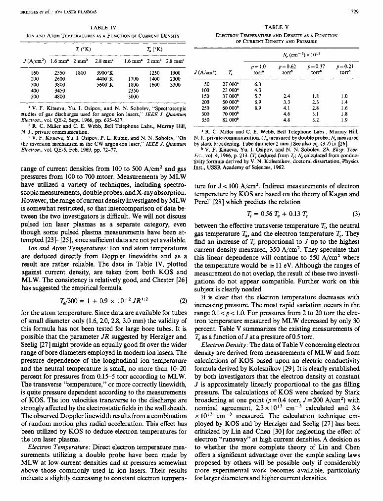
TABLE IV ION Ah?) ATOM TEMPERATURES AS A FUNCTION OF CURRENT DENSITY
Ti (“K) T. (OK)
J (Aim2) 1.6 m m p 2 m m b 2.8 mm’ 1.6 mm’ 2 m m b 2.8 mm’
160 2550 1800 3900°K 1250 1900 200 2600 4400°K 1700 1400 2300 300 3800 5600°K 1800 1600 3300 400 3450 2350 500 4800 3000
a V. F. Kitaeva, Yu. I. Osipov, and N. N. Sobolev, “Spectroscopic studies of gas discharges used for argon ion lasers,” ZEEE J. Quantum Electron., vol. QE-2, Sept. 1966, pp. 635-637.
R. C. Miller and C. E. Webb, Bell Telephone Labs., Murray Hill, N. J., private communication.
V. F. Kitaeva, Yu. I. Osipov, P. L. Rubin, and N. N. Sobolev, “On the inversion mechanism in the CW argon-ion laser,” ZEEE J. Quantum Electron., vol. QE-5, Feb. 1969, pp. 72-77.
range of current densities from 100 to 500 A/cm’ and gas pressures from 100 to 700 mtorr. Measurements by MLW have utilized a variety of techniques, including spectro- scopic measurements, double probes, and X-ray absorption. However, the range of current density investigated by MLW is somewhat restricted, so that intercomparison of data be- tween the two investigators is difficult. We will not discuss pulsed ion laser plasmas as a separate category, even though some pulsed plasma measurements have been at- tempted [23]-[25], since sufficient data are not yet available.
Ion and Atom Temperatures: Ion and atom temperatures are deduced directly from Doppler linewidths and as a result are rather reliable. The data in Table IV, plotted against current density, are taken from both KOS and MLW. The consistency is relatively good, and Chester [26] has suggested the empirical formula
TJ300 = 1 + 0.9 X lo-’ JR”’ (2)
for the atom temperature. Since data are available for tubes of small diameter only (1.6, 2.0, 2.8, 3.0 m m ) the validity of this formula has not been tested for large bore tubes. It is possible that the parameter JR suggested by Herziger and Seelig [27] might provide an equally good fit over the wider range of bore diameters employed in modem ion lasers. The pressure dependence of the longitudinal ion temperature and the neutral temperature is small, no more than 10-20 percent for pressures from 0.15-5 torr according to MLW. The transverse “temperature,” or more correctly linewidth, is quite pressure dependent according to the measurements of KOS. The ion velocities transverse to the discharge are strongly affected by the electrostatic fields in the wall sheath. The observed Doppler linewidth results from a combination of random motion plus radial acceleration. This effect has been utilized by KOS to deduce electron temperatures for the ion laser plasma.
Electron Temperature: Direct electron temperature mea- surements utilizing a double probe have been made by MLW at low-current densities and at pressures somewhat above those commonly used in ion lasers. Their results indicate a slightly decreasing to constant electron tempera-
TABLE V ELECTRON TEMPERATURE AND DENSITY AS A FUNCTION
OF CURRENT DENSITY AND FRESSURE
J(A/cm2) T p=1.0 p=0.62 t o e torf
50 27 oo(r 6.3 100 23 000’ 4.3 150 37ooob 5.7 2.4 200 50 ooob 6.9 3.3 250 60 ooob 8.9 4.1 300 70ooob 4.6 350 82 ooob 4.8
p=0.37 p=0.21 to+ torf
1.8 1 .o 2.3 1.4 2.8 1.6 3.1 1.8 3.2 1.9
* R. C. Miller and C. E. Webb, Bell Telephone Labs., Murray Hill, N. J., private communication. (Te measured by double probe; Ne measured by stark broadening. Tube diameter 2 mm.) See also eq. (3.2) in [26].
V. F. Kitaeva, Yu. I. Osipov, and N. N. Sobolev, Zh. Eksp. Teor. Fir.. vol. 4, 1966, p. 213. ( T . deduced from T , ; Ne calculated from conduc- tivity formula derived by V. N. Kolesnikov, doctoral dissertation, Physics Inst., USSR Academy of Sciences, 1962.
ture for Jc 100 A/cm’. Indirect measurements of electron temperature by KOS are based on the theory of Kagan and Perel’ [28] which predicts the relation
q = 0.56 T, + 0.13 T, (3)
between the effective transverse temperature q, the neutral gas temperature T,, and the electron temperature T,. They find an increase of T, proportional to J up to the highest current density measured, 350 A/cm*. They speculate that this linear dependence will continue to 550 A/cm’ where the temperature would be N 11 eV. Although the ranges of measurement do not overlap, the result of these two investi- gations do not appear compatible. Further work on this subject is clearly needed.
It is clear that the electron temperature decreases with increasing pressure. The most rapid variation occurs in the range 0.1 < p < 1.0. For pressures from 2 to 20 torr the elec- tron temperature measured by MLW decreased by only 30 percent. Table V summarizes the existing measurements of T, as a function of J at a pressure of 0.5 torr.
Electron Density: The data of Table V concerning electron density are derived from measurements of MLW and from calculations of KOS based upon an electric conductivity formula derived by Kolesnikov [29]. It is clearly established by both investigators that the electron density at constant J is approximately linearly proportional to the gas filling pressure. The calculations of KOS were checked by Stark broadening at one point (p = 0.4 torr, J = 200 A/cm’) with nominal agreement, 2.3 x 1013 cm-3 calculated and 3.4 x 1013 cm-3 measured. The calculation technique em- ployed by KOS and by Herziger and Seelig [27] has been criticized by Lin and Chen [30] for neglecting the effect of electron “runaway” at high current densities. A decision as to whether the more complete theory of Lin and Chen offers a signifmnt advantage over the simple scaling laws proposed by others will be possible only if considerably more experimental work becomes available, particularly for larger diameters and higher current densities.
730 PROCEEDINGS OF THE IEEE, MAY 1971
Neutral Atom Density: The neutral atom density is very difficult to measure in small capillary discharges. Absorp- tion of X-rays passing along the length of the capillary was employed by MLW to deduce total atom+ ion densities, but the results were reliable only at pressures greater than those employed in laser discharges. They observed a de- crease in neutral atom density with increasing atom tem- perature as would be expected from simple gas law con- siderations. However, the measured densities were con- sistently 20-40 percent higher than those calculated from the gas law relation
This is not surprising considering the strong dynamic forces acting on the gas (see the discussion on gas pumping which follows) and the small conductance of the discharge tubes. Miller [31] has suggested that the theory of thermal transpiration might be more appropriate to this situation since the atomic mean free path is comparable to the tube radius for the smaller bore lasers. The gas law relation has not been tested experimentally in larger bore lasers where it is most likely valid. Nonetheless, it is used by most of those who advance theoretical explanations of ion laser plasmas. Both KOS and Herziger and Seelig [27] use it to obtain the neutral number density needed in the electric conductivity calculation, and Lin and Chen [30] have used a more com- plete form in which the external pressure is set equal to the total pressure of atoms, ions, and electrons.
Electric Field Gradient: The axial electric field measured under condition of optimum' laser action (pRzO.1 torr c m ) [32] is observed to obey the relation [17], [26], [32]
E 3 = 6.5 V ( 5 )
for 0.5 <R < 7.5 mm. The dependence of E , on J and p is small for JR< 50 A/cm. Herziger and Seelig [32] find E , a J for J R > 200 A/cm. The laser discharge typically exhibits a small positive resistance except at low J (usually below laser threshold) where a pronounced negative re- sistance is observed [26]. Again the gradient is very constant at cold filling pressures near and above optimum and begins to rise only when the fill pressure is reduced well below the optimum value.
Magnetic Field: The experimental results discussed up to this point have all been taken with no axial magnetic field; in actual fact, very few plasma data have been measured for ion laser plasmas in a magnetic field. This may seem some- what surprising considering that almost all commercial CW ion lasers operate with a magnetic field to improve effi- ciency. Many investigators feel, however, that the magnetic field operates in a simple way to reduce ion loss by slowing down the electron transport to the walls, and that very little additional information will be learned about excita- tion mechanisms by studying the plasma in a magnetic field. This point of view is supported by measurements of
Somewhat lower optimum pressures apply to the krypton and xenon ion laser plasmas.
E ;3.0 n 5 2.5 v) a 82.0
F z Z 1.5 0 a v)
u. 1.0 0
k 0.5 9 I I 5 0 1 I I I ' I I I I I
0 02 0.4 0.6 0.8 1.0 1.2 1.4 1.6 1.8 2.0 2.2 2.4 MAGNETIC FIELD, kG
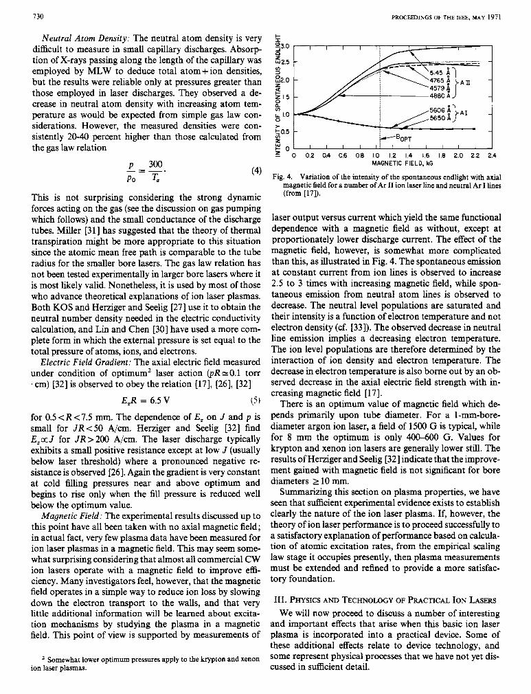
Fig. 4. Variation of the intensity of the spontaneous endlight with axial magnetic field for a number of Ar I1 ion laser line and neutral Ar I lines (from [17]).
laser output versus current which yield the same functional dependence with a magnetic field as without, except at proportionately lower discharge current. The effect of the magnetic field, however, is somewhat more complicated than this, as illustrated in Fig. 4. The spontaneous emission at constant current from ion lines is observed to increase 2.5 to 3 times with increasing magnetic field, while spon- taneous emission from neutral atom lines is observed to decrease. The neutral level populations are saturated and their intensity is a function of electron temperature and not electron density (cf. [33]). The observed decrease in neutral line emission implies a decreasing electron temperature. The ion level populations are therefore determined by the interaction of ion density and electron temperature. The decrease in electron temperature is also borne out by an ob- served decrease in the axial electric field strength with in- creasing magnetic field [ 171.
There is an optimum value of magnetic field which de- pends primarily upon tube diameter. For a l-mm-bore- diameter argon ion laser, a field of 1500 G is typical, while for 8 mm the optimum is only 400-600 G. Values for krypton and xenon ion lasers are generally lower still. The results of Herziger and Seelig [32] indicate that the improve- ment gained with magnetic field is not s i d c a n t for bore diameters 2 10 mm.
Summarizing this section on plasma properties, we have seen that sutficient experimental evidence exists to establish clearly the nature of the ion laser plasma. If, however, the theory of ion laser performance is to proceed successfully to a satisfactory explanation of performance based on calcula- tion of atomic excitation rates, from the empirical scaling law stage it occupies presently, then plasma measurements must be extended and refined to provide a more satisfac- tory foundation.
111. PHYSICS AND TECHNOLOGY OF PRACTICAL ION LASERS We will now proceed to discuss a number of interesting
and important effects that arise when this basic ion laser plasma is incorporated into a practical device. Some of these additional effects relate to device technology, and some represent physical processes that we have not yet dis- cussed in sufficient detail.
BRIDGES et al. : ION LASER PLASMAS 731
A . Gas Pumping in Zon Lasers
One of the interesting and practically important char- acteristics of the high-current-density low-gas-pressure ion laser discharge is the rapid pumping of gas from one end of the tube to the other. In the first CW ion lasers it was found that after tens of seconds of operation the filling gas would be pumped from the cathode and bore to the anode to such a degree that laser action would cease and the dis- charge would extinguish. A convenient solution to this problem is to provide some form of gas return path external to the discharge which connects the anode and cathode ends and allows an external equalizing flow of neutral gas to occur [lo]. A gas return path having approximately the same diameter as the laser bore, but somewhat greater length to prevent electrical breakdown, is found to be adequate to achieve maximum laser output and adequate discharge stability.
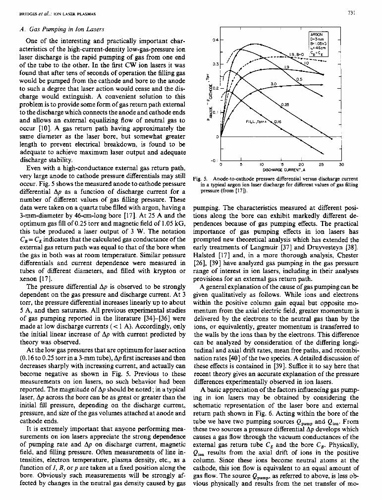
Even with a high-conductance external gas return path, very large anode to cathode pressure differentials may still occur. Fig. 5 shows the measured anode to cathode pressure differential Ap as a function of discharge current for a number of different values of gas filling pressure. These data were taken on a quartz tube filled with argon, having a 3-mm-diameter by 46-cm-long bore [17]. At 25 A and the optimum gas fill of 0.25 torr and magnetic field of 1.05 kG, this tube produced a laser output of 3 W. The notation C, = CE indicates that the calculated gas conductance of the external gas return path was equal to that of the bore when the gas in both was at room temperature. Similar pressure differentials and current dependence were measured in tubes of different diameters, and filled with krypton or xenon [ 171.
The pressure differential Ap is observed to be strongly dependent on the gas pressure and discharge current. At 3 torr, the pressure differential increases linearly up to about 5 A, and then saturates. All previous experimental studies of gas pumping reported in the literature [34]-[36] were made at low discharge currents (< 1 A). Accordingly, only the initial linear increase of Ap with current predicted by theory was observed.
At the low gas pressures that are optimum for laser action (0.16 to 0.25 torr in a 3-mm tube), Ap first increases and then decreases sharply with increasing current, and actually can become negative as shown in Fig. 5. Previous to these measurements on ion lasers, no such behavior had been reported. The magnitude of Ap should be noted; in a typical laser, Ap across the bore can be as great or greater than the initial fill pressure, depending on the discharge current, pressure, and size of the gas volumes attached at anode and cathode ends.
It is extremely important that anyone performing mea- surements on ion lasers appreciate the strong dependence of pumping rate and Ap on discharge current, magnetic field, and filling pressure. Often measurements of line in- tensities, electron temperature, plasma density, etc., as a function of Z, B, or p are taken at a fixed position along the bore. Obviously such measurements will be strongly af- fected by changes in the neutral gas density caused by gas
I I I I I I
0.4 i
t -0.1 I I I 1 1 I
0 5 10 15 20 25 30 DlSCrtARGE CURRENT,A
Fig. 5. Anode-to-cathode pressure differential versus discharge current in a typical argon ion laser discharge for different values of gas Ming pressure (from [ 171).
pumping. The characteristics measured at different posi- tions along the bore can exhibit markedly different de- pendences because of gas pumping effects. The practical importance of gas pumping effects in ion lasers has prompted new theoretical analysis which has extended the early treatments of Langmuir [37] and Druyvesteyn [38]. Halsted [ 171 and, in a more thorough analysis, Chester [26], [39] have analyzed gas pumping in the gas pressure range of interest in ion lasers, including in their analyses provisions for an external gas return path.
A general explanation of the cause of gas pumping can be given qualitatively as follows. While ions and electrons within the positive column gain equal but opposite mo- mentum from the axial electric field, greater momentum is delivered by the electrons to the neutral gas than by the ions, or equivalently, greater momentum is transferred to the walls by the ions than by the electrons. This difference can be analyzed by consideration of the differing longi- tudinal and axial drift rates, mean free paths, and recombi- nation rates [40] of the two species. A detailed discussion of these effects is contained in [39]. Suffice it to say here that recent theory gives an accurate explanation of the pressure differences experimentally observed in ion lasers.
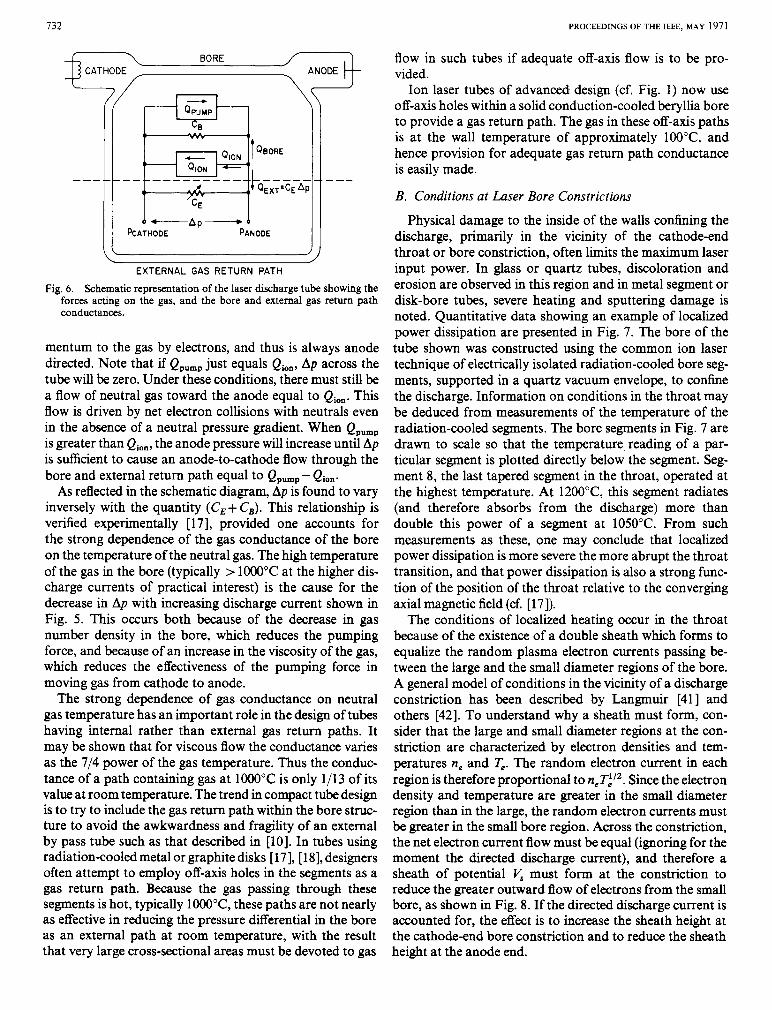
A basic appreciation of the factors iduencing gas pump ing in ion lasers may be obtained by considering the schematic representation of the laser bore and external return path shown in Fig. 6. Acting within the bore of the tube we have two pumping sources Qpump and Qion. From these two sources a pressure differential Ap develops which causes a gas flow through the vacuum conductances of the external gas return tube CE and the bore C,. Physically, Qion results from the axial drift of ions in the positive column. Since these ions become neutral atoms at the cathode, this ion flow is equivalent to an equal amount of gas flow. The source Qpump, as referred to above, is less ob- vious physically and results from the net transfer of mo-
732
BORE CATHODE ANODE
PCATHODE PANWE
EXTERNAL GAS RETURN PATH
Fig. 6. Schematic representation of the laser discharge tube showing the forces acting on the gas, and the bore and external gas return path conductances.
mentum to the gas by electrons, and thus is always anode directed. Note that if Qpump just equals Qion, Ap across the tube will be zero. Under these conditions, there must still be a flow of neutral gas toward the anode equal to Qion. This flow is driven by net electron collisions with neutrals even in the absence of a neutral pressure gradient. When Qpump is greater than Qion, the anode pressure will increase until Ap is sufficient to cause an anode-to-cathode flow through the bore and external return path equal to Qpump - Qion.
As reflected in the schematic diagram, Ap is found to vary inversely with the quantity (C,+ C,). This relationship is verified experimentally [17], provided one accounts for the strong dependence of the gas conductance of the bore on the temperature of the neutral gas. The high temperature of the gas in the bore (typically > 1ooo"C at the higher dis- charge currents of practical interest) is the cause for the decrease in Ap with increasing discharge current shown in Fig. 5 . This occurs both because of the decrease in gas number density in the bore, which reduces the pumping force, and because of an increase in the viscosity of the gas, which reduces the effectiveness of the pumping force in moving gas from cathode to anode.
The strong dependence of gas conductance on neutral gas temperature has an important role in the design of tubes having internal rather than external gas return paths. It may be shown that for viscous flow the conductance varies as the 7/4 power of the gas temperature. Thus the conduc- tance of a path containing gas at 1OOO"C is only 1/13 of its value at room temperature. The trend in compact tube design is to try to include the gas return path within the bore struc- ture to avoid the awkwardness and fragility of an external by pass tube such as that described in [lo]. In tubes using radiation-cooled metal or graphite disks [17], [18], designers often attempt to employ off-axis holes in the segments as a gas return path. Because the gas passing through these segments is hot, typically 1000°C, these paths are not nearly as effective in reducing the pressure differential in the bore as an external path at room temperature, with the result that very large cross-sectional areas must be devoted to gas
PROCEEDINGS OF THE IEEE, MAY 1971
flow in such tubes if adequate off-axis flow is to be pro- vided. Ion laser tubes of advanced design (cf. Fig. 1) now use
off-axis holes within a solid conduction-cooled beryllia bore to provide a gas return path. The gas in these off-axis paths is at the wall temperature of approximately 100°C, and hence provision for adequate gas return path conductance is easily made.
B. Conditions at Laser Bore Constrictions
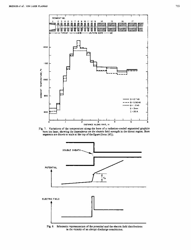
Physical damage to the inside of the walls confining the discharge, primarily in the vicinity of the cathode-end throat or bore constriction, often limits the maximum laser input power. In glass or quartz tubes, discoloration and erosion are observed in this region and in metal segment or disk-bore tubes, severe heating and sputtering damage is noted. Quantitative data showing an example of localized power dissipation are presented in Fig. 7. The bore of the tube shown was constructed using the common ion laser technique of electrically isolated radiation-cooled bore seg- ments, supported in a quartz vacuum envelope, to confine the discharge. Information on conditions in the throat may be deduced from measurements of the temperature of the radiation-cooled segments. The bore segments in Fig. 7 are drawn to scale so that the temperature reading of a par- ticular segment is plotted directly below the segment. Seg- ment 8, the last tapered segment in the throat, operated at the highest temperature. At 1200"C, this segment radiates (and therefore absorbs from the discharge) more than double this power of a segment at 1050°C. From such measurements as these, one may conclude that localized power dissipation is more severe the more abrupt the throat transition, and that power dissipation is also a strong func- tion of the position of the throat relative to the converging axial magnetic field (cf. [17]).
The conditions of localized heating occur in the throat because of the existence of a double sheath which forms to equalize the random plasma electron currents passing be- tween the large and the small diameter regions of the bore. A general model of conditions in the vicinity of a discharge constriction has been described by Langmuir [41] and others [42]. To understand why a sheath must form, con- sider that the large and small diameter regions at the con- striction are characterized by electron densities and tem- peratures ne and T,. The random electron current in each region is therefore proportional to n,T;/'. Since the electron density and temperature are greater in the small diameter region than in the large, the random electron currents must be greater in the small bore region. Across the constriction, the net electron current flow must be equal (ignoring for the moment the directed discharge current), and therefore a sheath of potential V , must form at the constriction to reduce the greater outward flow of electrons from the small bore, as shown in Fig. 8. If the directed discharge current is accounted for, the effect is to increase the sheath height at the cathode-end bore constriction and to reduce the sheath height at the anode end.
BRIDGES et al. : ION LASER PLASMAS 133
I I I I I I I I I I I SEGMENT NO.
1 2 3 4 5 6 7 8 9 O I I I 2 1 3 14 15 16 17
:E -THROAT -b. UNIFORM BORE
fi ... ..........
if .-J**: .....
I 2 3 DISTANCE ALONG AXIS, in
4 5
Fig. 7. Variations of the temperature along the bore of a radiationcooled segmented graphite bore ion laser, showing the dependence on the electric field strength in the throat region. Bore segments are drawn to scale at the top of the figure (from [43]).
DOUBLE SHEATH
I
POTENTIAL
Fig. 8. Schematic representation of the potential and the electric field distributions in the vicinity of an abrupt discharge constriction.