proceedings of the workshop on software engineering methods for
TRANSCRIPT

Daniel Lübke (editor)
Workshop onSoftware Engineering Methods for Service-Oriented Architecture 2007(SEMSOA 2007)
ProceedingsSEM SOA
Hannover 2007
Preface
Service Oriented Architecture (SOA) is a new emerging style for building business applications: The software is directly based on the business processes which are used to compose software services into an application.
SOA has become a hype: Many researchers and practitioners explore this area. Whereas the ongoing SOA discussion mostly concentrates on dynamic service discovery, new business methods and the business process side, the development side is normally neglected. One important question in this regard is which (proven) software engineering methods can be applied well in SOA implementation projects. What gaps and pitfalls have been discovered in practice, which remain without feasible solutions? Since mostly all SE methods have been geared towards object-oriented software design in the last years, methods and practices have to be adapted to meet the requirements of the new architectural style.
This workshop therefore aims to bring together researchers and practitioners from the SOA field in order to exchange ideas and experiences related to adopted or new software engineering methods for SOA and experiences related to them. This encompasses methods, models and techniques for the whole software life cycle. Hopefully, this will result in new ideas and cooperations in this field.
For this workshop, there were 10 submissions. Each submission was reviewed by at least 3 program committee members. At the end 8 papers were accepted.
Hopefully, this workshop will be successful. I like to thank all the people who worked towards that goal. Especially, I like to thank all program committee members, who invested their time in reviewing the submissions, and all the members of the Software Engineering Group at the Leibniz Universität Hannover for helping to organize this workshop.
Hannover, May 2007 Daniel Lübke

Program Committee Members
• Luciano Baresi, Politecnico di Milano, IT • Nico Brehm, University Oldenburg, DE • Nicolas Gold, King's College London, GB • Katrina Leyking, DKFI, DE • Daniel Lübke, Leibniz Universität Hannover, DE • Jorge Marx Gómez, University Oldenburg, DE • Jan Mendling, WU Wien, A • Andreas Schmietendorf, FHW Berlin, DE • Kurt Schneider, Leibniz Universität Hannover, DE • Branimir Wetzstein, University Stuttgart, DE • Uwe Zdun, Vienna University of Technology, A • Olaf Zimmermann, IBM Zurich Research Laboratory, CH

Table of Contents
Multi-staged and Multi-viewpoint Service Choreography Modelling Alistair Barros, Gero Decker, Marlon Dumas ...................................................1
Dealing with User Requirements and Feedback in SOA Projects Daniel Lübke, Eric Knauss...............................................................................16
Semantic Model-Driven Development of Service-centric Software Architectures Claus Pahl, Ronan Barrett ...............................................................................31
Architectural Decision Models as Micro-Methodology for Service-Oriented Analysis and Design Olaf Zimmermann, Jana Koehler, Leymann Frank..........................................46
Towards a Holistic Architecture Platform Tony Shan, Winnie Hua....................................................................................61 Service-oriented Development of Federated ERP-Systems Nico Brehm, Jorge Marx Gómez......................................................................76
Resource Metrics for Service-Oriented Infrastructures Dmytro Rud, Andreas Schmietendorf, Reiner Dumke ......................................90
Model Driven Testing of SOA-based Software Chris Lenz, Joanna Chimiak-Opoka, Ruth Breu ..............................................99

Multi-staged and Multi-viewpoint ServiceChoreography Modelling
Alistair Barros1, Gero Decker2, Marlon Dumas3
1 SAP Research Centre, Brisbane, [email protected]
2 Hasso-Plattner-Institute, University of Potsdam, [email protected]
3 Queensland University of Technology, [email protected]
Abstract. Recent approaches to service-oriented systems engineeringstart by capturing the interactions between services from the perspec-tive of a global observer, leading to so-called service choreographies.The rationale is that such choreographies allow stakeholders to agreeon the overall structure and behaviour of the system prior to developingnew services or adapting existing ones. However, existing languages forchoreography modelling, such as WS-CDL, are implementation-focused.Also, these proposals treat choreographies as monolithic models, withno support for multiple viewpoints. This paper proposes a multi-stagedand multi-viewpoint approach to choreography modelling. For the initialstages, the approach promotes the partitioning of choreography modelsand the design of role-based views; while for subsequent stages, milestoneand scenario models are used as an entry point into detailed interactionmodels. The paper presents analysis techniques to manage the consis-tency between viewpoints. The proposal is illustrated using a sales andlogistics model.
1 Introduction
As implementation-level web service interoperability standards mature, the needfor analysis and design methods for service-oriented systems becomes even morepressing. In early proposals for service-oriented analysis and design methods [8, 2,22, 16], global models of service interactions, also known as conversation protocolsor service choreographies, play a key role during the initial stages of analysis anddesign. Service choreographies capture the interactions in which a collection ofservices engage, from the perspective of an ideal observer who would be ableto see every interaction occurring between the involved services. By providing a“birds-eye” view over interactions, service choreographies allow business and ITstakeholders to build a common understanding of the structure and behaviourof the overall system, prior to approaching implementation issues.
Languages such as BPSS [20] and WS-CDL [14] have been proposed as a basisfor modelling choreographies. However, these languages focus on detailed inter-
1

2 Alistair Barros, Gero Decker, Marlon Dumas
action flows and treat choreographies as monolithic development artifacts. WS-CDL in particular goes down to supporting the description of choreographies ina quasi-executable form, using programming constructs such as sequence, block-structured conditional and loop structures, and variable assignment. While theselanguages partly support an implementation-independent approach to service-oriented system design, it is questionable that they are suitable for the earlyphases of the development lifecycle, where the incremental acquisition of a com-mon understanding by multiple stakeholders with different concerns and back-grounds is crucial. It is unlikely that business stakeholders and system analystsoperating at a high level of abstraction will benefit from manipulating chore-ography models that include executable data manipulation steps. Instead, theyare likely to be interested in viewing choreographies without the interaction flowdetails (e.g. role-based viewpoints), or to view milestones and specific scenarios.Only at later stages does the refinement of choreography models into executablecode becomes a concern. Thus, languages and methods for choreography mod-elling should be compatible with multi-staged and multi-viewpoint design. Bysupporting multiple modelling viewpoints, it is possible to break down a ser-vice design into smaller more manageable parts that are handled by differentstakeholders.
In this setting, the proposition of this paper is an approach to choreographymodelling based on viewpoints layered on top of a choreography modelling lan-guage, namely Let’s Dance [21]. Let’s Dance has a formal semantics defined interms of π-calculus [6] and has been shown to be expressive enough to capturecommon service interaction patterns [3] and to serve as a basis for generating lo-cal views on service interactions for subsequent refinement into executable mod-els [21]. In this paper, we define role-based, milestone-based, and scenario-basedviewpoints into service choreographies, and propose techniques for managing theconsistency between these viewpoints and the interaction-based viewpoints na-tively supported by Let’s Dance. The outcome is a set of notational elementsand consistency checking techniques that provide a basis for defining service-oriented analysis and design methods that bridge the gap between business andIT concerns. The notational elements have been used to capture a refined ver-sion of a logistics collaboration model proposed by the Voluntary Inter-industryCommerce Solutions Association (VICS).4 Meanwhile, the consistency checkingalgorithms have been validated through implementation and testing.
After an informal introduction to the proposal using the VICS global logisticsmodel (Section 2), the paper defines an abstract syntax for each of the proposedmodelling viewpoints (Section 3). Next, the techniques for inter-viewpoint con-sistency verification are presented in Section 4. Finally, related work is discussedin Section 5 while Section 6 concludes.
4 See www.vics.org
2

Multi-staged and Multi-viewpoint Service Choreography Modelling 3
2 Multi-view choreography design by example
This section provides the practical setting through which the proposed chore-ography modelling viewpoints and extensions to the Let’s Dance language aremotivated and developed. Insights are drawn from a case study inspired by theSales and Logistics component of the VICS EDI Architecture Guide. The casestudy is related to the supply chain between retailers and manufacturers, cov-ering processes where products are ordered through cyclic stock replenishmentagreements over a time-horizon (e.g. 12 months), shipped and paid for. Alongthe way, shipments need to be managed and optimised through different types ofcarriers (land, rail, air, ocean), consolidated at intermediaries, crossed throughthe “red tape” of customs and quarantine, and delivered to consignment nodeswhere they are dispatched to retail stores. As a result of delivery, fulfilment ofan order needs to be assessed with respect to quantity, timeliness and damageto ensure quick turn-around for payment and reimbursement. To close the loop,supply and consumer patterns are dynamically fed back into the next cycles ofmerchandising and collaborative forecasting, planning and replenishment.Domains and roles. End-to-end modelling of interactions of value-chains asvast as Sales and Logistics require a careful scoping of processes being anal-ysed. To facilitate such scoping and provide a focus on models (e.g. interactionmodels) developed for common business objectives, we propose the notion ofcollaboration domains. These domains group a set of logically related models.The set of collaboration domains for the Sales & Logistics case study is depictedin Figure 1. As apparent from the figure, the collaboration domains (ellipses)scope different areas of business interest. For example, a distinction is made be-tween Collaborative Forecasting Product Replenishment (out of which an orderis produced), Logistics (governing shipment of goods), Payments, Exceptions,Order Release and Product Merchandising. Given the size and complexity ofdomains, we propose that they should be arranged in a hierarchical structure.For example, in Figure 1, we can see that the logistics domain is decomposedinto four sub-domains: Tendering, Carrier Appointment, Delivery, and Claims& Returns.
To go from collaboration domains into individual processes with detailed in-teractions, we propose an intermediate viewpoint: the role-based choreographyview. A role-based choreography is defined for each leaf-level domain (since non-leaf domains are purely used for the purpose of abstraction). This viewpointis illustrated for the Delivery domain in Figure 1. This viewpoint shows col-laborating roles (boxes) and their interaction dependencies, expressed throughchannels. A channel captures the fact that there is at least one direct interactionbetween two or more roles and the purpose of this/these interactions. Channelsare represented by small circles on lines.
Cardinality constraints on channels are used to express how many partici-pants of one role can interact with one participant of the other role. As illus-trated, a Shipper interacts with a number of Carriers for Carrier Planning, whilea Carrier interacts with one Shipper. A Shipper, a Consignee and a Consolida-tor all interact for the purpose of agreeing on a Detailed Shipment Schedule.
3

4 Alistair Barros, Gero Decker, Marlon Dumas
Exceptions
Consignee
Carrier
Land Carrier
Rail Carrier
Ocean Carrier
AirCarrier
Breakdown Service
Locative Service
Insurance
Shipper
Manu-facturerRetailer
Distribution Center
Store
Consolidator
Customs / Quarantine
Delivery Negotiation
Detailed Shipment Schedule
Carrier Planning
Coverage Notification
Detailed Ship-ment Schedule
Clearance Pre-notification
Clearance Monitoring
Delivery Monitoring
Truck Breakdown Provision
Traffic Optimization Guidance
Arrival/Pickup Conf.
Special Cover
Delivery Planning
1
1
1
1
1
1 1
1
1
1
1
Delivery / Dispatch Plan
Shipment Schedule
1
1 1
1
1
* 1
1
1
*
* 1*
1 *
1 11 *
* *
Dispatch*
Product Merchandising
Order Release
Payments
Collaborative Forecasting Product
Replenishment
Tendering
Carrier Appointment
DeliveryClaims & Returns
Logistics
Fig. 1. High-level role-based view for Delivery domain of Logistics
Multiplicity of roles can be explicitly shown, as with Shipper and Carrier forinstance. This indicates that several participants of role Carrier (overlaid boxes)are involved in one choreography instance as opposed to only one participant ofrole Shipper taking part (single box).
Another notational element, used in the representations for the Carrier andthe Consignee roles, is that of role hierarchies (roles within roles). Role hierar-chies can be used to express different relationships, and the exact relationshipbeing represented needs to be specified by the modeller. In the case of the Con-signee, the hierarchies mean that at least one of the sub-roles is involved in theinteraction expressed against the super-role, i.e. a part-of relationship. Consigneealso illustrates that further interaction dependencies can be expressed betweensub-roles. Alternatively, the relationship between super- and sub-roles could re-flect specialisation, where all sub-roles carry the same interaction dependenciesas the super-role, and each may carry additional dependencies. This applies tothe Carrier and its sub-roles.
With interaction dependencies between roles, through channels, in place,individual message exchanges can be captured. We propose that channels areassigned a set of message interactions in terms of message type and direction offlow. By this assignment to channels, the message interactions between collabo-rating roles is captured, although they remain unordered.
Milestones, scenarios and interactions. The models described so far arestatic: they do not describe control flow relationships between interactions. Be-low, we introduce viewpoints where interactions and their relationships are cap-tured in more detail. Since the number of participants and interactions can bevery large, these detailed viewpoints can be difficult to build and comprehend.Thus, a mechanism is needed to partition these models. This is achieved throughthe notion of milestones depicted in Figure 2.
Milestones (diamonds) represent the main global states choreography in-stances can be in and as such are used as “sign-posts”. In complex choreogra-
4

Multi-staged and Multi-viewpoint Service Choreography Modelling 5
Payments Exceptions
CollaborativeForecasting ProductReplenishment
CarrierAppointment
Delivery
CarriersSelected
OperationalDeliveryContractEstablished
DeliveryEventPlanning
Variationsfrom DeliveryContract Finalised
Ad-hocRequestsFinalised
ShipmentSchedulePrepared
CarrierVariationsProcessing
ShipmentScheduleFinalised
VariationsPrepared
CarrierVariationsIdentified
VariedCarriageIssued
FinalShipmentScheduleIssued
Customs/QuarantinePre-ClearanceProcessing
CarrierPick-up/DeliveryConfirmation
Consolid.Pick-up/DeliveryConfirmation
ShipmentCommenced
Claims & Returns
Fig. 2. Milestones related to Delivery domain
phies, milestones are useful since the details of processes which lead to milestonesbeing reached can be omitted. To illustrate the point, Figure 2 depicts milestonesprimarily concerning Delivery, with some links to related milestones in processesof other domains shown. In this example, some milestones are related throughPrecedes relationships (arrowed lines). Some milestones might never be reachedfor a particular instance of a choreography. For example and as explained in de-tails later, if a guard attached to an interaction evaluates to false, the interactionis skipped, and so are all other interactions that directly or transitively follow itaccording to the Precedes relation. Also, some milestones may be skipped as aresult of Inhibits relationships. An Inhibits relationship (line crossed by a bar)expresses that if a milestone is reached, the target milestone can no longer bereached for the current instance of the choreography (i.e. it will be skipped). Inthe example, a Shipment Schedule Prepared milestone being reached will resultin either a Shipment Schedule Finalised (SSF) or Carrier Variations Identified(CVI) milestone being eventually reached, but not both since these milestones“inhibit” each other. If we want to express that a milestone can still be reachedeven if a “preceding” milestone has been skipped, we should use a Weak Precedesrelationship (arrowed dashed line) instead of a Precedes ones. Following the sameexample, Final Shipment Schedule (FSS) is “weak preceded” by the both theSSF and CVI milestones, and thus the FSS milestone will be reachable after one
5

6 Alistair Barros, Gero Decker, Marlon Dumas
of these two milestones has been reached and the other has been skipped. Thisexample corresponds to a more general pattern where a Weak Precedes relation-ship is used to join two mutually exclusive paths. Another example of a WeakPrecedes is given by the Delivery Event Processing milestone (e.g. next week’sdelivery) which is reached after the Operational Delivery Contract Establishedmilestone is reached, whether or not the milestones Variations from DeliveryContract Finalised and Ad-Hoc Requests Finalised have been reached.
The last extension is to introduce scenarios, or specific “threads” of interac-tions, and to merge these scenarios to obtain detailed interaction-based chore-ography models (also called interaction models for short). The modelling of in-teractions is the central theme of choreography languages, however support forcapturing scenarios (a well-established feature of analysis and design) is leftopen. With milestones in place, under our approach, scenarios identify interac-tions which serve to progress the milestones. Figure 3 illustrates how scenariosrelate to milestones drawn from Figure 2, starting with a scenario yielding amilestone that is used as input for a second scenario. In the third scenario de-tailed in the example, the Retailer and Manufacturer negotiate required stock,and finally the Manufacturer releases order quantities. The Manufacturer thendetermines through the Shipper whether the allocated Carriers have capacity ornot for the shipment, and accordingly two exclusive milestones result from thescenario. How large or small a scenario is, should reflect user requirements. Inaddition, scenarios might be split into sub-scenarios in order to allow for differentvariants of parts of a scenario.
Store/inventory report
Retailer Manufacturer
Final delivery replenishment
Manufacturer Retailer
Replenishment acknowledgement
Retailer Manufacturer
Carrier capacity sufficient
Manufacturer Retailer
Carrier capacity insufficient
Manufacturer Retailer
Shipment Schedule Prepared
CarrierVariationsIdentified
ShipmentSchedule Finalised
InvestigateReplenishment forDelivery Event
Fig. 3. Scenario for replenishment
Design method. The above considerations are summarised as a choreographydesign method in Figure 4. The rounded rectangles in this figure depict the ac-tivities of the choreography design method. The arrows describe which otheractivities are influenced by the outcome of an activity. First, domains need tobe identified and decomposed into sub-domains. Next comes the identification ofparticipants in the different domains. This identification mostly takes place earlyin the process but participants can also be included in later stages. With par-ticipants in place, role-based choreography models can be obtained by defininginteraction dependencies between them.
6

Multi-staged and Multi-viewpoint Service Choreography Modelling 7
Domain scoping
Participant identification
Milestone definition
Scenario modeling
Message identification
Choreography finalization
Service implementation
for Role N
Service implementation
for Role 1
Choreography View for Role N
Choreography View for Role 1
Fig. 4. Method for choreography design
Milestone models provide a high-level view of the behavioural aspect of chore-ography models, describing the main global states choreography instances canbe in. Scenarios describe which interactions are needed to get from one mile-stone to another and thus only focus on one part of a choreography. Duringscenario modelling the designers might realise that they have to introduce moreparticipants than they have considered so far. Furthermore, re-discussing thescope of a domain might be needed when scenario modelling goes down to thelevel of message exchanges. It might not be obvious to what domain a certaininteraction belongs to, and this may affect the grouping of scenario models andinteraction models into domains. For example, does a scenario triggered by aninteraction “Pickup Appointment Change Request” belong to the domain “Car-rier Appointment” or to “Delivery”? Message exchanges between the differentparticipants are identified in this activity. First, only high-level descriptions aregiven. Later, message structures and contents are specified in detail.
The domain-relevant parts of the scenarios are aggregated into an integratedinteraction model for the domain. Therefore, all participants, milestones, inter-actions and relationships between them are captured in this integrated chore-ography. Subsequently, the individual participants’ views on the choreographymodel are generated and distributed to the participants who now proceed todesign and implement their parts of the choreography. In our previous work [21],we have proposed algorithms for generating such local participants’ views in thecontext of the Let’s Dance language. Finally, existing implementations might bechecked to determine if they already comply with the choreography model or ifchanges have to be made.
3 Choreography modelling viewpoints
The top-level viewpoint of the proposed choreography design method is the do-main model. A domain model is composed of a set of domains arranged in ahierarchical relation. Leaf-level domains are mapped to different models corre-sponding to the proposed viewpoints on a choreography. Specifically, each leafdomain maps to: (i) a role-based model, (ii) a milestone model, (iii) a set of in-teraction models corresponding to scenarios, and (iv) an integrated interaction
7

8 Alistair Barros, Gero Decker, Marlon Dumas
model. In this section, we present an abstract syntax for each of these types ofmodels.
3.1 Role-based choreography models
The previous section has already motivated role-based models and has intro-duced the intended meaning of the different elements of such models. Figure 5summarises the corresponding graphical representations: Rectangles representroles. Concrete participants are bound at design-time or at run-time. Small
Role2
G
E FA B C Dm11 *
1 1
Fig. 5. Diagram elements for role-based models
circles represent channels while message links are depicted as dashed arrows.Message links are directed channels with a particular message type assigned.Cardinality of channels is represented by either “1” or “*” attached to the end-point of a channel. Multiplicity of roles is represented by a double rectangle likefor role B. Hierarchy is represented by containment in the diagram.
We define a role-based choreography model CR to be a tuple (R, RM , C,Senders, Receivers, Card, Msg, CM , Parent) where:
– R is the set of all roles,– RM : R → {one,many} is a function assigning a multiplicity to a role,– C is the set of all channels,– Senders, Receivers : C → ℘(R) assign the set of roles to a channel who can
send / receive messages over the channel, if the sets of senders and receiversare disjunct, the channel is a message link (ML := {ml ∈ C | Senders(c) ∩Receivers(c) = ∅}),
– Card : {(c, r) ∈ C × R | r ∈ Senders(c) ∪ Receivers(c)} → {one,many} isa function assigning a cardinality to role r for channel c,
– Msg is the set of all message types,– CM : ML → Msg is a partial function linking message links to message
types,– Parent ⊆ R × R specifies the hierarchical relationships between a role and
its sub-roles (Parent must be acyclic) and– the cardinality “many” is only used in the presence of the multiplicity
“many” of the corresponding role: ∀(c, r) ∈ Card [c = many ⇒ RM(r) =many].
3.2 Milestone, scenario and interaction models
In previous work [21] we have presented Let’s Dance as a language for modellingservice interactions and their dependencies. Below, we enrich the language with
8

Multi-staged and Multi-viewpoint Service Choreography Modelling 9
milestones. That way models like they were motivated in section 2 are specified.Figure 6 contains the graphical elements for representing milestone and inter-action models. Milestones are represented by diamond shapes and interactions
m1 {A, B}
message msg5
A B
message msg6
B Crepeat until x msg sent (B)
If condition X fulfilled (B)
message msg3
A B
message msg4
B C
message msg1
A B
message msg2
B C
m2 {all} m3 m4 m5 m6
Fig. 6. Diagram elements for milestone and interaction diagrams
using rectangles. These roles indicated in brackets describe which participanthas to be notified as soon as the milestone is reached. If all participating rolesare to be synchronised “all” appears in brackets or the brackets are omitted.
The Precedes relationship between two elements (milestones or interactions)e1 and e2 indicates that e1 must have been executed / reached before e2 can beexecuted / reached. A WeakPrecedes relationship between e1 and e2 indicatesthat e2 can only be executed / reached after e1 has been either executed /reached or after it has been skipped. An Inhibits relationships between e1 ande2 indicates that e2 cannot be executed / reached after e1 has been executed/ reached (i.e. e2 is then skipped). Two-directional Inhibits relationships arerepresented like in the case of m3 and m4.
Interactions can either be elementary or composite. In the case of elementaryinteractions a participant of a certain role sends a message of a given type toanother participant. In Figure 6 a participant of role A sends a message of typem1 to a participant of role B. Composite interactions allow for grouping of oneor more interactions. Interactions can be guarded, i.e. they may only occur if aguard condition evaluates to true, or they can be repeated. It is specified whichparticipant evaluates the guard condition and the repetition expression.
Below, we introduce three types of models corresponding to different view-points into a choreography: milestone, scenario and interaction models. Milestonemodels are composed only of milestones and relationships between them. Mean-while, scenario models are composed of milestones, interactions and relationshipsbetween them. The purpose of a scenario model is to show how to go from aset of milestones to another. Scenario models are not limited to one domain andmay be used to show dependencies between milestones and interactions from dif-ferent domains. Scenario models can be nested, i.e. different sub-scenario models
9

10 Alistair Barros, Gero Decker, Marlon Dumas
may refine a given scenario model, showing specific variants. A similar notioncan be found in Message Sequence Charts [18] which capture specific paths ofinteractions between a number of parties. But in contrast to traditional MSCs,we allow scenario or sub-scenario model to show alternative paths (i.e. we allowconditional branching in scenario models)5. Finally, interaction models show allmilestones and interactions from one domain as well as their relationships.
We introduce a unified abstract syntax for milestone, scenario and interactionmodels by defining interaction models as the most general viewpoint, and theother two as special cases. An interaction model CI is a tuple (I, M , RI, RT ,GI, R, RM , c0, Precedes, WeakPrecedes, Inhibits, Parent, Sends, Receives,MR, Msg , IM ) where
– I is the set of milestones and interactions,– M ⊆ I is the set of milestones,– RI ⊆ I \M is the set of repeated interactions,– RT : RI → {w, r, fs, fc} links a repeated interaction to a repetition type
(either while, repeat, for each (sequential) or for each (concurrent)),– GI ⊆ I \M is the set of guarded interactions,– R is the set of roles,– the function RM : R → {many, one} specifies whether many or just one
participant of a role is involved in the choreography,– c0 ∈ I \M is the top-level interaction of the choreography,– Precedes,WeakPrecedes, Inhibits ⊆ I × I are binary relations over I,– Parent ⊆ (I \ M) × I is the relation between interactions and their direct
sub-interactions and milestones, defining the set of elementary interactionsEI := {i ∈ (I \M) | i /∈ range(Parent)}
– the partial functions Sends,Receives : EI → R link elementary interactionsto sending and receiving roles,
– MR : M → ℘(R) links milestones to sets of roles that are to be synchronised,– Msg is the set of all message types and– IM : EI → Msg links elementary interactions to message types.
A milestone model CM is an interaction model where I = M ∪ {c0}. Mean-while, a scenario model is an interaction model where no milestone is both thesource and the target of Precedes and/or WeakPrecedes relationships, that is:∀m ∈ M [¬∃i, j ∈ I ((i Precedes m ∨ i WeakPrecedes m) ∧ (m Precedes j ∨m WeakPrecedes j))]
4 Consistency analysis
Consistency checking is an essential aspect in multi-viewpoint approaches [8].In this section we introduce consistency rules between role-based choreographymodels and interaction models as well as between milestone models and inter-action models based on the abstract syntaxes given in the previous sections.5 While this feature is not supported in traditional MSCs, it is supported in various
extensions to MSCs such as Live Sequence Charts (LSCs) [10].
10

Multi-staged and Multi-viewpoint Service Choreography Modelling 11
4.1 Role-based choreography models vs. interaction models
Consistency between a role-based choreography model CR = (RR, RMR, CR,SendersR, ReceiversR, CardR, MsgR, CMR, ParentR) and an interactionmodel CI = (II , MI , RII , RTI , GII , RI , RMI , c0, Precedes, WeakPrecedes,Inhibits, ParentI , SendsI , ReceivesI , MRI , MsgI , IMI) is given if:
– all roles of CI are present in CR and have the same multiplicity: RI ⊆ RR
and RMI ⊆ RMR,– for all elementary interactions there is a corresponding channel (one channel
can correspond to many interactions): ∀i ∈ EII [∃c ∈ CR (SendsI(i) ∈SendersR(c) ∧ ReceivesI(i) ∈ ReceiversR(c) ∧ (CMR(c) = IMI(i) ∨ c /∈dom(CMR)))] and
– each role has to be involved in at least one corresponding elemen-tary interaction for every channel it is connected to: ∀c ∈ CR∀r ∈SendersR(c)∪ReceiversR(c) [∃i ∈ EI ((r ∈ {SendsI(i)}∩SendersR(c)∨r ∈{ReceivesI(i)} ∩ReceiversR(c)) ∧ (CMR(c) = IMI(i) ∨ c /∈ dom(CMR)))].
4.2 Milestone models vs. interaction models
Consistency between a milestone model CM = (IM , MM , RIM , RTM , GIM ,RM , RMM , c0M , PrecedesM , WeakPrecedesM , InhibitsM , ParentM , SendsM ,ReceivesM , MRM , MsgM , IMM ) and an interaction model CI = (II , MI ,RII , RTI , GII , RI , RMI , c0I , PrecedesI , WeakPrecedesI , InhibitsI , ParentI ,SendsI , ReceivesI , MRI , MsgI , IMI) is given if all constraints defined in themilestone model are ensured in the interaction model. Constraints are given bythe PrecedesM , WeakPrecedesM and InhibitsM relationships.
1: I(1,1) := {i ∈ II | ¬∃j ∈ RII (j Parent∗I i ∧RTI(j) 6= r)∧2: ¬∃j ∈ II(j Precedes∗I i ∧ (j ∈ GII ∨ (∃k ∈ II(k Inhibits+ j))))}3: ∀(m1, m2) ∈ PrecedesM [m1 Precedes+
I m2∨4: (m1 ∈ I(1,1) ∧m1(PrecedesI ∪WeakPrecedesI)
+m2)]5: ∀(m1, m2) ∈ WeakPrecedesM [m1(PrecedesI ∪WeakPrecedesI)
+m2]6: ∀(m1, m2) ∈ InhibitsM [∃i, j ∈ II(i InhibitsI j ∧ j Precedes∗I m2∧7: (i Precedes∗I m1 ∨ (i ∈ I(1,1) ∧ i(PrecedesI ∪WeakPrecedesI)
∗m1)))]
Fig. 7. Consistency checking between milestone models and interaction models
Figure 7 presents how consistency between a milestone model CM and aninteraction model CI can be checked. We assume that all composite interactionsare repeated and that all interactions and milestones are reachable. Further-more, all Inhibits relationships must have an effect. In previous work [21] wehave introduced algorithms for expanding choreography models and for identify-ing unreachable interactions and obsolete Inhibits relationships. A PrecedesM
relationship is ensured in CI if there is a path of PrecedesI relationships fromone milestone to the other or if the first milestone is always eventually reached(m1 ∈ I(1,1)) and there is a path of PrecedesI and WeakPrecedesI relation-ships (lines 3-4). Lines 1-2 present how I(1,1) can be identified: There must be
11

12 Alistair Barros, Gero Decker, Marlon Dumas
no preceding guarded interaction or an InhibitsI relationship targeting a pre-ceding interaction. A WeakPrecedesM relationship is ensured if there is a pathof PrecedesI and WeakPrecedesI relationships. Finally, an InhibitsM relation-ship is ensured if a preceding interaction of m1 is the source of an InhibitsI
relationship targeting a preceding interaction of m2.Additional constraints can be added in the interaction model. For example,
if two milestones m1 and m2 are not ordered in the milestone model, we canintroduce a PrecedesI relationship between m1 and m2 in the interaction modelwithout violating the consistency rules.
5 Related work
Service choreography description has been the subject of intensive research andstandardisation. An early attempt was BPSS [20] where global models are cap-tured as flows of interactions using flowchart-like constructs. WSCI [1] representsanother approach wherein global service interaction models are defined as col-lections of inter-connected local models (as opposed to a single global model).Control dependencies are described within each individual local model. Morerecently, the WS-CDL initiative [14] led to a language that follows the line ofBPSS insofar as global service behaviour is described as flows of interactions.WS-CDL goes further than BPSS in the level of details at which interaction flowsare described. In fact, WS-CDL can be seen as a programming-in-the-large lan-guage for Web services since it relies on imperative programming constructs. Thework presented in this paper is complementary to these initiatives, as it definesviewpoints and notational elements that operate at a higher level of abstraction.
In [4], the authors consider the use of state machines for describing localmodels of service interactions. While state machines lead to simple models forhighly sequential scenarios, they may lead to spaghetti-like models when used tocapture scenarios with parallelism and cancellation (e.g. scenarios where a giveninteraction may occur at any time during the execution of another set of inter-actions). Nonetheless, state machines have been shown to be a suitable formalfoundation for reasoning about service models, e.g. determining the bounded-ness of service queues in service conversations [11]. This latter reference surveysa number of approaches for describing service interaction models based on com-municating state machines.
The concept of multi-viewpoint modelling of distributed systems has been ad-vocated in the RM-ODP reference model [12], which defines various viewpointssuch as enterprise viewpoint (high-level purpose and policies), computationalviewpoint (functional decomposition and interface definition), information view-point, etc. Dijkman [7] defines a framework for capturing multiple viewpointsover distributed systems and applies the framework to formalise RM-ODP’s en-terprise and computational viewpoints. Dijkman’s framework is defined as anextension to an Architecture Description Language (ADL), namely ISDL, thatincludes notational elements similar to those found in the role-based and inter-action viewpoints considered in this paper, although ISDL does not directly sup-
12

Multi-staged and Multi-viewpoint Service Choreography Modelling 13
port our role decomposition construct. A discussion on the application of ISDLfor service choreography modelling is presented in [17]. However, the suitabil-ity of ISDL for capturing complex service interactions (e.g. involving multicast)is unproven. Also, ISDL does not have a counter-part for the milestone-basedviewpoint which is useful when dealing with large service choreographies.
Colombo et al [5] propose a methodology for service composition that startswith the definition of so-called social models that capture business entities andtheir dependencies. These models are similar to our role-based models, with thedifference that our role-based models capture more detail than social models,e.g. role-based models capture the multiplicity of interaction dependencies be-tween roles. In the second phase of the methodology of Colombo et al., a processmodel capturing the behaviour of a service composition is constructed. Thisprocess model is derived from a set of ECA rules and it is encoded as a finitestate machine. This approach is suitable for capturing sequential interactions,but arguably not for capturing concurrent interactions. In contrast, we take asstarting point a language in which concurrent interactions can be naturally cap-tured. Indeed, if two interactions in a Let’s Dance model are not related througha “Precedes” dependency, either directly or transitively, these interactions mayoccur in any order or concurrently.
Foster et al. [9] propose a method for Web service composition in whichscenario models expressed as MSCs are compared with orchestration models ex-pressed in BPEL. In this context, orchestration models are choreography modelsprojected over a single role (i.e. a local view on a choreography model). To checkconsistency between scenario models and orchestration models, these models arecompiled into Labelled Transition Systems (LTSs). The resulting LTSs are com-pared in terms of their traces to check that the behaviour of the scenario modelis contained in the behaviour of the orchestration model. Our proposal is com-plementary insofar as we focus on capturing the relationships between scenariomodels and higher-level models (i.e. milestone models and role-based models).
Seel et al. [19] present a requirements framework for inter-organizationalbusiness process models. A distinction is made between interaction points forcollaborating employees and departments and interaction points for informationsystems. Corresponding extensions to Event-driven Process Chains (EPC [15])are introduced.
The role-based view presented in this paper can be seen as a formalizedrepresentation of the “service decomposition” diagrams proposed in [13]. Ourrole-based views contain more information than those of [13] and they can bedirectly linked with milestone, scenario and detailed interaction models.
6 Conclusion and outlook
We motivated the need for choreography languages to unhinge from present fo-cus on implementation considerations concerning message interactions, in serviceto analysis and design of wide-spanning B2B domains, and the collaborationsof interacting participants in particular. Our proposal was illustrated using the
13

14 Alistair Barros, Gero Decker, Marlon Dumas
VICS global supply chain standard, offering insights into the large and intricatelandscape that needs to be penetrated to get down to detailed interaction-basedchoreography models. We developed domain scoping (essentially equivalent toprocess hierarchies) and role-based choreography models as horizontal parti-tions, together with milestones as vertical partitions. For lower levels, we refinedinteraction-based choreography modelling to support scenarios through whichmilestones are progressed. Consistency of models was formally analysed, withone question being left open: how to integrate a set of scenario models for agiven domain into a single choreography model? This integration, which is leftas future work, should be guided by the milestone model of the domain, giventhat each scenario model covers a different set of milestones.
Further research will spawn in two directions which are relevant for impactin web services composition environments. The first is to validate the modellingviews against further use cases and to refine the modelling proposals accordingly.The second is to determine how well such extended considerations of choreogra-phy modelling can be mapped into intermediate, more implementation focusedlanguages such as WS-CDL and WS-BPEL. Along the way, the Let’s Dance toolwill be extended to support the extensions proposed.Acknowledgement. The authors wish to thank Remco Dijkman for valuablefeedback on a draft of this paper. The third author is funded by a fellowshipfrom Queensland Government and SAP.
References
1. Assaf Arkin et al. Web Service Choreography Interface (WSCI) 1.0. Technicalreport, Aug 2002. http://www.w3.org/TR/2002/NOTE-wsci-20020808.
2. K. Baına, B. Benatallah, F. Casati, and F. Toumani. Model-driven web services de-velopment. In Proceedings of the 16th International Conference on Advanced Infor-mation Systems Engineering (CAISE’04), Riga, Latvia, 7-11 June 2004. Springer.
3. A. Barros, M. Dumas, and A. ter Hofstede. Service interaction patterns. In Pro-ceedings of the 3rd International Conference on Business Process Management,Nancy, France, September 2005. Springer.
4. B. Benatallah, F. Casati, F. Toumani, and R. Hamadi. Conceptual modeling of webservice conversations. In 15th International Conference on Advanced InformationSystems Engineering (CAiSE), volume 2681 of LNCS, pages 449–467, Klagenfurth,Austria, June 2003.
5. E. Colombo, J. Mylopoulos, and P. Spoletini. Modeling and analyzing context-aware composition of services. In Proceedings of the 3rd International Confer-ence on Service-Oriented Computing (ICSOC), pages 198–213, Amsterdam, TheNetherlands, December 2005. Springer.
6. G. Decker, J. M. Zaha, and M. Dumas. Execution semantics for service choreogra-phies. In Proceedings 3rd International Workshop on Web Services and FormalMethods (WS-FM 2006), Vienna, Austria, Sept 2006. Springer.
7. R. Dijkman. Consistency in Multi-Viewpoint Architectural Design. PhD thesis,University of Twente, The Netherlands, 2006.
8. R. Dijkman and M. Dumas. Service-oriented design: A multi-viewpoint approach.International Journal of Cooperative Information Systems, 13(4):337–368, Decem-ber 2004.
14

Multi-staged and Multi-viewpoint Service Choreography Modelling 15
9. H. Foster, S. Uchitel, J. Magee, and J. Kramer. LTSA-WS: a tool for model-based verification of web service compositions and choreography. In Proceedingof the 28th international conference on Software Engineering (ICSE) – ResearchDemonstration, pages 771–774, Shanghai, China, May 2006. ACM Press.
10. D. Harel and R. Marelly. Come, Let’s Play: Scenario-Based Programming UsingLSCs and the Play-Engine. Springer, 2003.
11. R. Hull and J. Su. Tools for composite web services: a short overview. SIGMODRec., 34(2):86–95, 2005.
12. ITU-T/ISO. Open distributed processing reference model. Technical Report ITU-T X.901..904 – ISO/IEC 10746-1.4, ITU-T/ISO, 1994–1997.
13. S. Jones. Enterprise SOA Adoption Strategies. InfoQ Enterprise Software Develop-ment Series, 2006. Available at: http://www.infoq.com/minibooks/enterprise-soa.
14. N. Kavantzas, D. Burdett, G. Ritzinger, and Y. Lafon. Web services choreographydescription language version 1.0, w3c candidate recommendation. Technical report,November 2005. http://www.w3.org/TR/ws-cdl-10.
15. G. Keller, M. Nttgens, and A.-W. Scheer. Semantische Prozessmodellierung aufder Grundlage Ereignisgesteuerter Prozessketten (EPK). Verffentlichungen desInstituts fr Wirtschaftsinformatik (IWi) 89, Universitt des Saarlandes, January1992.
16. M. Papazoglou and W. van den Heuvel. Service-oriented design and developmentmethodology. International Journal of Web Engineering and Technology (IJWET),2006.
17. D. Quartel, R. Dijkman, and M. van Sinderen. Methodological support for service-oriented design with ISDL. In Proceedings of the 2nd Intenational Conference onService-Oriented Computing (ICSOC), pages 1–10, New York NY, USA, November2004. Springer.
18. E. Rudolph, J. Grabowski, and P. Graubmann. Tutorial on Message SequenceCharts. Computer Networks and ISDN Systems, 28(12):1629–1641, 1996.
19. C. Seel and D. Vanderhaeghen. Meta-Model based Extensions of the EPC forInter-Organisational Process Modelling. In Proceedings 4th Workshop on Geschft-sprozessmanagement mit Ereignisgesteuerten Prozessketten (EPK 2005), volume167 of CEUR, pages 117–136, Hamburg, Germany, December 2005.
20. UN/CEFACT and OASIS. ebXML Business Process Specification Schema (Version1.01). http://www.ebxml.org/specs/ebBPSS.pdf, 2001.
21. J. M. Zaha, M. Dumas, A. ter Hofstede, A. Barros, and G. Decker. Service in-teraction modeling: Bridging global and local views. In Proceedings 10th IEEEInternational EDOC Conference (EDOC 2006), Hong Kong, China, October 2006.
22. O. Zimmermann, P. Krogdahl, and C. Gee. Elements of service-oriented analysisand design. Available at: www.ibm.com/developerworks/library/ws-soad1, 2004.
15

Dealing with User Requirements and Feedbackin SOA Projects
Daniel Lubke and Eric Knauss
Leibniz Universitat Hannover, FG Software EngineeringWelfengarten 1
D-30167 Hannover, Germany{daniel.luebke,eric.knauss}@inf.uni-hannover.de
http://www.se.uni-hannover.de
Abstract. SOA projects normally influence the work of many people –especially in large organizations. The software will alter the way peoplewill work in the future and it will hopefully support the accomplishmentof their tasks. However, for building a SOA, business processes need to beformalized. Using wrong process descriptions is going to hinder insteadof support people’s work. Therefore, integrating the future users into thedevelopment project is crucial: Requirements need to be gathered andthe system needs to be refined over time in order to improve and adaptto new situations. In this paper, we propose a methodology combinedof Use Cases and an Experience Forum to better communicate withthe system’s users. Use Cases are used for elicitating requirements andderiving business processes in the requirements phase. Afterwards, theExperience Forum is used for collecting feedback in order to improve thesystem over time.
Key words: SOA, Use Case, Business Process, Experience Forum, UserFeedback
1 Introduction
Service-oriented Architecture (SOA) is an emerging style for architecting largebusiness applications. They promise to better align the business’ IT with thebusiness processes. However, so far SOA has mostly been seen as a way forexecuting fully automated business processes, e.g. by using the Business ProcessExecution Language (BPEL) [1]. In reality, users still play a central role intoday’s business processes: Extensions like BPEL4People [10] and generationof user interfaces [12] try to close the gap on the technical side. Because therequirements for semi-automatic business processes are heavily influenced by theusers, SOA projects need to address the users’ wishes during the whole softwarelife cycle. This is even more the case in organizations which are formalizingtheir business processes during the “SOAfication” of their infrastructure: Theseorganizations build up business processes in a very short time. Consequently,the business processes will likely contain errors and unwanted side effects due totheir immature nature.
16

2 Daniel Lubke and Eric Knauss
These problems can be addressed by analyzing and improving the project’sinformation flows between the users and the developers. This paper will presenta general information flow model for SOA projects in section 2. In this model thecommunication between the different parties will be enhanced by better integrat-ing Use Cases with Business Processes in the Requirements Engineering phase(see section 3), and an Experience Forum for ongoing refinement of the system byfacilitating user feedback (see section 4). Afterwards, an example project is pre-sented in section 5, which utilizes the described techniques. Section 6 discusseshow to integrate these measures into different software development processes.Finally, related work is presented and conclusions are given.
2 Information Flow Model
Software projects, and consequently SOA projects as well, are a very commu-nication intensive endeavor. Much of projects’ successes is bound to efficientand well-organized communication. In the end, every information item passedthrough a project can be traced back to some requirement. Consequently, thecommunication of requirements is essential. In order to illustrate a course-grainedrequirements flow through a SOA project, the FLOW notation [16] is used.
SOA projects in business environments are based on business processes. Con-sequently, these are an integral part of the system requirements. However, theyalone are not sufficient, because they lack details from the users’ points of view.This gap is closed by Use Cases [4]. Business Processes and Use Cases togetherform the representation of a system’s functional requirements. These are passedon to the design, implementation, and testing phase. Finally, the product is usedby a large, diverse and often distributed user base.
A simplified and generalized information flow model is illustrated in figure 1.
Fig. 1. Simplified FLOW Model for a General SOA Project
17

Dealing with User Requirements and Feedback in SOA Projects 3
Concerning the requirements, there are two imminent problems in projectsorganized this way:
1. Both formalized business processes and Use Cases contain information aboutthe process to be carried out. While both contain what users of a systemmust do they are geared towards different target groups: Use Cases are writ-ten from the perspective of a single actor while business processes offer anoverview about all participants’ activities. Managing both models mandatesadditional effort. If one model could at least be semi-automatically gener-ated, the development team could invest more resources into actual imple-mentation activities.
2. After delivering the first version of an application, it is necessary to collectfeedback from users and incorporate the needed changes into the system. Thefeedback can relate to the implementation or the new business processes inplace. Since SOA systems are expected to be a long-term investment, thedevelopment should be iterative in order to keep up with occurring changes.Each iteration should not only try to incorporate new functionality, butalso learn from the experiences the users made with the previous versions.However, SOA projects normally serve a large user base. Reaching the usersand effectively transporting their feedback into the development organizationis inherently difficult.
Both problems will be addressed in the following sections.
3 Generation of Use Cases and Business Processes
Requirements Engineering (RE) is one of the core Software Engineering activi-ties. RE aims to identify and document the requirements a system must fulfill.Over the years, many techniques have evolved in order to support RE-relatedactivities. Among them are Use Cases which are well-suited to document func-tional requirements of user-centric systems. Use Cases partition the system intoscenarios related to a main actor. Use Cases are normally written down in atabular template as used in the example later on (see figure 3).
The Use Case Template is a good help to prepare interviews with users:The interviewers know what information they must elicit from the interviewees.Furthermore, due to their textual nature, Use Cases can be understood by normalusers who are not accustomed to UML and other technical notations.
However, SOA projects are normally not based on Use Cases but on busi-ness processes, because processes can be easily transformed to service compo-sitions. Therefore, the business processes must be documented as well as partof RE-related activities – if this has not already been done in the organization.Consequently, a SOA project can be initiated under two scenarios:
– The organization wants to introduce software but does not know exactly theunderlying business processes. It is important to note that business processesare performed and therefore in place: Every single person knows what she
18

4 Daniel Lubke and Eric Knauss
or he is supposed to do. However, a global overview is missing and no pro-cesses have been formalized. Therefore, the organization in contrast to theindividuals does not know the business processes.
– The organization has defined business processes in place, and wants to sup-port those by new software systems. This means, management and otherresponsible persons have the overview, but details from the users’ point ofview, which are necessary for implementing IT systems, are missing.
In the first scenario, Use Cases can be used to interview users and documentthe requirements. If those Use Cases are documented with fine-grained pre- andpostconditions, the Use Cases can easily be transformed into business processes.It is mandatory to document the Use Cases with literally equal conditions in or-der to support automatic matching. The following algorithm for achieving a UseCase transformation to business processes in EPC notation has been presentedin [11]:.
1. Preconditions and triggers are realized as events since their conditions fulfillthe same role as events do. Because all preconditions must be met and thetrigger must occur in order to start the Use Case, all events are joined usingan AND join in the EPC if this rule results in more than one event. The firststep in the main scenario is inserted after the AND join as an EPC function.
2. All steps of the main scenario are mapped to a linear control flow in anEPC. Each step is mapped to an EPC function. Functions are connected byusing trivial OK-events. The step’s actor becomes the role responsible forthe created EPC function. Objects normally cannot be easily extracted fromthe Use Case templates and are therefore not handled by this algorithm.
3. Success Guarantees are – like the preconditions and triggers – conditionsconcerning a system. These conditions are true after the successful executionof a Use Case. They are mapped to EPC events which are inserted afterthe last function of the main scenario. Since all guarantees must hold aftercompletion, all events (in case of multiple guarantees) are connected usingan AND split.
4. Minimal Guarantees are discarded. These guarantees normally representnon-functional requirements which cannot be visualised using EPCs. Sincethey must be valid before, during and after the Use Case, they do not changethe system at all.
5. Extensions are introduced using an XOR connector. After the proceedingfunction, an XOR split is introduced which splits into the OK-event and anstart event for each extension. A step with 2 extensions therefore becomes afunction followed with an XOR split to 3 paths.
6. All Extension Steps are handled like steps in the main scenario. Extensionsto Extension Steps are handled recursively using these rules.
7. Jumps typically occurring from one extension step to a step in the main sce-nario are realized using XOR joins. A join is introduced before the functionrepresenting the step which is the jump target.
For the second start scenario, in which business processes are already avail-able, the business process needs to be partitioned into Use Cases. Such Use Cases
19
Dealing with User Requirements and Feedback in SOA Projects 5
represent sub-processes which are owned by only one actor. Only the scenariowith its extensions, the main actor, and the conditions can be extracted fromthe business process. All other fields must be filled by interviewing the users ofthe envisioned system.
The main problem is to partition the business process into sub-processesbelonging only to one actor. As a starting point, the whole business processcan be partitioned into personal views, as presented in [8]. These sub-processescan be transformed to a scenario each. The splits in the business process, i.e.decision points and parallel activities must be mapped to extensions. In [6] analgorithm is presented, which uses logical transformations to change an EPC toa representation, that can be mapped to a Use Case scenario and correspondingextensions:
After this transformation, all Use Cases have been converted to a set of busi-ness processes. These sub-processes need to be joined into one large businessprocess. This is done by joining the start events and end events by assumingthat events with the same name are actually the same. Only the correspond-ing boolean connectors (e.g. a parallel and-split) have to be introduced. Twomethods for doing this are covered in [11].
In order to practically create Use Cases conforming to the described con-straints, tool support is necessary. Intelligent Use Case Editors, like the UseCase DODE [5], can help the Use Case creator to follow these rules by givinginstant feedback. Such an editor needs to provide at least (a) the presented tem-plate, (b) must warn whenever the conditions do not match the given format,and (c) must detect similar condition names which may indicate typing errors.
4 User Feedback
Development of complex software systems is a knowledge-intensive endeavor.Developers do not only need technical skills, but also domain knowledge, userinterface design capabilities, and so forth. Whenever many roles and stakeholdersare involved, large projects will rarely meet all customer requirements at the firstattempt. There is usually a lengthy period of building, using, and improving thesystem.
With SOA, such a complex system is structured in a number of independentlydeveloped services that need to cooperate as an integrated system. There is anabundance of aspects that developers need to consider when they create SOAsystems or services.
However, they typically lack domain knowledge: They do not and cannotknow what customers and users really want. At the same time, customers andusers do not know what could reasonably be expected from such a system. Fischerhas called this the “symmetry of ignorance” [7]. Due to the wicked nature of theproblem, and the symmetry of ignorance, several iterations and improvementsteps will be needed to produce a satisfactory SOA system [15].
The problem is even harder with most SOA projects, because the softwareserves a large and often distributed user base.
20

6 Daniel Lubke and Eric Knauss
To connect users and the development organization an Experience Forum,as presented in [13] can be used to facilitate feedback: An Experience Forum isintegrated into the client application. At each step, the user is shown the hand-book and experiences of other users relevant to the current step. Additionally,the user can submit feedback to the activity she or he is currently performing.Feedback can be of three types:
Bug Reports: Users can instantly submit software defects they find. These canbe propagated into the development process. Bug Reports affect only one UseCase as they will address defects in a screen which affects the current user.
Feature Requests: Users observe features which would improve their dailytasks during their work. They can submit these feature requests via the Ex-perience Forum as well. Those requests are fed as well into the developmentprocess.
Process Shortcomings and Improvements: Users can leave comments con-cerning the business process. For example, documents which are forwardedto them but never used can be criticized. Such feedbacks affect the overallprocess. The development organization together with the business processdesigners need to take those comments into account.
Process Experiences: The users are actually the ones who perform the busi-ness process. They have experiences how to interpret certain rules and howto handle unexpected situations. If they have mastered a new situation, theycan enter their newly gained experience into the Experience Forum and letall other users profit from it. This kind of feedback founds a new Communityof Practice among the relevant users.
The main advantage of an Experience Forum is the possibility to automati-cally capture the context of feedback in a SOA: The system knows which functionin which process is currently performed by which user because the service com-position already has this information. Therefore, the feedback can automaticallybe assigned to the underlying business function and retrieved whenever anotheruser performs the same business function.
As stated above, the context contains the reference to the business processposition it was made in and the submitter. Additionally, the language is storedin the context. Only feedback understandable by a certain user is retrieved andpresented.
Figure 2 shows an Experience Forum integrated into a client application. Onthe right hand side, it is readily accessible and usable with only some mouseclicks. This low threshold is very important in order to improve user acceptance.If the Experience Forum was somewhere hidden in the menus or hard to use, itwould not be put into use by the users.
5 Example Project
The example project is taken from a university project. The software and theprocess for managing student exams and thesis had to be newly designed. Partic-
21
Dealing with User Requirements and Feedback in SOA Projects 7
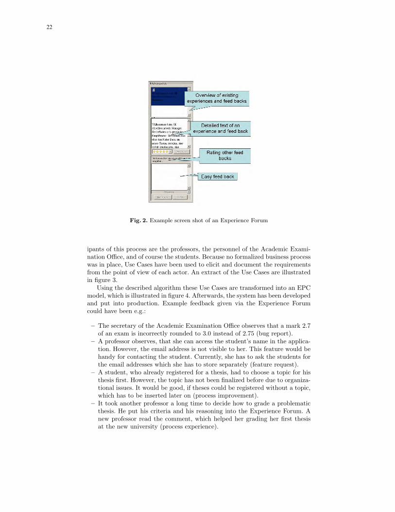
Fig. 2. Example screen shot of an Experience Forum
ipants of this process are the professors, the personnel of the Academic Exami-nation Office, and of course the students. Because no formalized business processwas in place, Use Cases have been used to elicit and document the requirementsfrom the point of view of each actor. An extract of the Use Cases are illustratedin figure 3.
Using the described algorithm these Use Cases are transformed into an EPCmodel, which is illustrated in figure 4. Afterwards, the system has been developedand put into production. Example feedback given via the Experience Forumcould have been e.g.:
– The secretary of the Academic Examination Office observes that a mark 2.7of an exam is incorrectly rounded to 3.0 instead of 2.75 (bug report).
– A professor observes, that she can access the student’s name in the applica-tion. However, the email address is not visible to her. This feature would behandy for contacting the student. Currently, she has to ask the students forthe email addresses which she has to store separately (feature request).
– A student, who already registered for a thesis, had to choose a topic for histhesis first. However, the topic has not been finalized before due to organiza-tional issues. It would be good, if theses could be registered without a topic,which has to be inserted later on (process improvement).
– It took another professor a long time to decide how to grade a problematicthesis. He put his criteria and his reasoning into the Experience Forum. Anew professor read the comment, which helped her grading her first thesisat the new university (process experience).
22

8 Daniel Lubke and Eric Knauss
Use Case #1: Student applies for Thesis
Primary Actor Student
Stakeholders Student: wants to apply easilySecretary (Academic ExaminationOffice): wants easy to use/read formsfor further handling registration
Minimal Guarantees none
SuccesssGuarantees
Application is submitted
Preconditions none
Triggers Student wants to write thesis
Main SuccessScenario
1 Student fills out form with personaldata
2 Student submits form to AcademicExamination Office
Extensions none
Use Case #2: Academic Examination Officeapproves Thesis
Primary Actor Secretary (Academic Examination Office)
Stakeholders Secretary (Academic Examination Office):wants easy to use/read forms for furtherhandling registrationManager (Academic Examination Office):wants short handling times
Minimal Guarantees Student's data are handled according toregulations
SuccesssGuarantees
Student may write Thesis
Preconditions none
Triggers Application is submitted
Main SuccessScenario
1 Secretary checks if student has 80% ofCredit Points
2 Secretary approves application
Extensions 1a If Student has less than 80% of CreditPoints thenSecretary denies Application
Fig. 3. Use Cases for describing the new System
The first three feedbacks have been fed into the development cycle. Howto proceed from having the feedback to actually using it, is dependent on thedevelopment methodology used. In the next section, integration into severaldevelopment processes is presented.
6 Development Process Integration
While an Experience Forum is a technical mechanism for collecting and facil-itating user feedback, it needs to be carefully integrated into the developmentprocess used within the project to be successful. The Experience Forum is tobe used after the first release used by real users. This will normally be the firstproduction release but can also be a preview version in use by a limited numberof users.
Figure 5 shows an overview of the activities in requirements engineering. Thefollowing list explains how the Experience Forum can generally be integrated intoeach activity:
Requirements Analysis (or: system analysis)Elicitation The Experience Forum supports the activity of requirements
elicitation by encouraging users to write down their issues. Neverthelessa requirements engineer has to sort the issues by their different types:requirements that affect the software (real requirements like bug-reportsor new requirements), requirements that affect the business model andissues that support the business process with domain knowledge.
Interpretation In this activity the requirements engineer has to refine theraw requirements to make them tangible (ideally making them testable).The benefit of using the Experience Forum is the link between the raw
23

Dealing with User Requirements and Feedback in SOA Projects 9
Student wants to write thesis
Student fills out form with
personal data
Student looks through list of
available topics
Ok: Student fills out form with personal data
Ok: Student looks through list
of available topics
Student submits form to
Academic Examination
Office
Student chooses most interesting
topic
Application is submitted
Ok: Student chooses most
interesting topic
Secretary checks if student has 80% of Credit
Points
Student asks supervisor to get
the topic
Student has picked a topic
XOR
Student has less than 80% Credit
Points
Ok: Secretary checks if student has 80% of Credit
Points
Secretary approves
application
Secretary denies application
Ok: Secretary denies
application
Student may write thesis
V
Supervisor hands out topic
...
Fig. 4. Business Process extracted from Use Cases
Fig. 5. Overview of requirements engineering and its activities.
24

10 Daniel Lubke and Eric Knauss
requirements and the location in the business process or software ap-plication it applies to. This helps the requirements engineer to identifystakeholder. representatives. The ambiguities and inconsistencies in thecomments and experiences still have to be clarified by the requirementsengineer.
Negotiation The identification and resolution of inconsistencies and con-flicts in the requirements as well as the prioritization of requirementsdefine this activity. Obviously this activity demands flair, a fact that iseven aggravated by the transparency the Experience Forum introduced(see section 6.3) – especially, if bugs and feature requests are assigned alow priority.
Documentation This activity transforms the raw requirements of the Ex-perience Forum into a form best suited for the software developmentprocess.
Verification / validation The inspection of form and content is supportedby the Experience Forum’s context information.
Requirements Management All activities that deal with requirements man-agement should incorporate the Experience Forum:Change Management Solved issues have to be labeled or deleted, issues
that apply to parts of the software or business process that have beenchanged must be revised.
Tracing The Experience Forum contains valuable information about thecontext of requirements. So solutions that aim at traceability shouldtake the Experience Forum in account, too.
The development process itself is supposed to be an iterative developmentprocess. Since feedback can only be collected from a first working software ver-sion, improvements originating from the Experience Forum can consequentlyonly be added from the second iteration or software version onwards.
6.1 A Document-Based Process
An Experience Forum can enhance the communication flow between the users,the responsible persons for requirements and the development team in document-based development processes. The new communication structure can be seen infigure 6.1.
Our example process defines the role of the experience and requirements en-gineer. This role is responsible for refining the working experiences in the foruminto requirements. Another responsibility is to sort the new requirements andgive them as change request either to the process designers or to the softwarechange control board.
The process designers will adjust the business process which will normallygenerate additional change requests for the software.
The software change control board gives the clearance for the change requeststo the software developers. Now the new release of the software is created. Beforeit can finally be made available for the users, the experience and requirements
25

Dealing with User Requirements and Feedback in SOA Projects 11
Fig. 6. Experience Base integrated into a SOA project
engineer has to adjust the experiences of the forum to the new release. At thispoint a refinement of the experiences in the Experience Forum of the old releaseinto best practices (and similar activities proposed in [2]) can be made. For therequirements management process it is important to mark the experiences thatlead to the new requirements as closed issues at this point.
Developers will normally have read access to the information necessary tocomplete their assignments and the users can access their information as well,possibly forming a Community of Practice.
With the introduction of the new software release the next iteration is started.The Experience Forum is seeded with the refined experiences from the last releaseand the software reflects the latest version of the business process.
6.2 Scrum
Whenever a development process is in place which is not iterative by default,the Experience Forum approach cannot be used because it requires multipleiterations to incorporate the feedback into the later software versions. Whenorganizations have non-iterative processes in use, one way to make these devel-opment processes iterative is wrapping them in Scrum.
Scrum [3] is an agile management methodology, partitioning the whole de-velopment project into 30 day iterations called Sprints. The product-ownermaintains a list of requirements ordered by priorities, the product-backlog. Thedevelopment-team takes as much of the requirements from this list as they wantto implement in the next 30 days and puts them into the sprint-backlog. Withina sprint the requirements in this sprint-backlog cannot be changed from outsidethe team. However, the product-owner may append new requirements to theproduct-backlog during a sprint.
Therefore, the product-owner is responsible for requirements analysis and toincorporate information gathered by the Experience Forum into the product-backlog. Due to the fixation of requirements during a Sprint, information gath-ered by the Experience Forum can only be implemented during the third or afollowing Sprint.
26

12 Daniel Lubke and Eric Knauss
6.3 Advantages and Pitfalls
The concept of an Experience Forum has – independent of the development pro-cess – many advantages: Users are able to give easily and quickly feedback duringtheir daily work. The threshold is thereby reduced improving the probability ofgetting feedback. While the user submits information, the application’s and pro-cess contexts are automatically captured: Issues are linked to the user interfaceand the current process element. This is especially easy if - as in our prototypesystem - the user interface is generated from the process description. Therefore,the system can automatically link between user interface elements and the partof the process it supports. Requirements Engineers or similar roles are therebysupported in the requirement interpretation because they can better understandand realize the feedback without needing to recreate the whole situation whichnormally is not well-described. This also applies to the developers: Wheneverthey get a defect assigned, they can also see the context to which the defectapplies to.
However, Experience Forums - if used wrongly - can have negative effects: Ifusers are willing to give feedback to the software and processes they are using andthey are affected by, they expect that things are getting better. If the feedbackis not used or seems to be not used due to long response times, the motivationof the user-base may degrade and acceptance may decrease. These risks must beguarded against which in essence means the process integration must be carefullydone. Especially, a user notification, what status the user’s feedback has, if andwhen it will be considered, can mitigate that risk.
Furthermore, one should be aware of that an Experience Forum can onlyassist in making existing processes and software incrementally better but will notlead to radically new processes. If a company wants to completely re-engineertheir processes it may not be the tool of choice. However, in this case an alreadyused Experience Forum can be beneficial: Process Designers can use the gatheredexperiences and information to learn from prior weaknesses and problems.
7 Related Work
Profiting from information contained in Use Cases for other models and devel-opment phases has always been a goal in software development projects, whichoften deal with business processes.
Cockburn himself only mentions the possibility of applying Use Cases forderiving business processes. He offers a template in [4] but no rules or advisehow to proceed from there.
The field of model-driven development has tried to combine the concept ofUse Cases with its models. Instead of tabular and textual descriptions, UMLsequence diagrams or similar models are used [9]. A Use Case is consequentlydenoted in Use Case diagrams and refined in other models thereby eliminatingthe textual description. This can pose a problem when communicating with non-technical users. A process for UML-based development of business processes
27

Dealing with User Requirements and Feedback in SOA Projects 13
is given in [14]. Missing from such approaches are capabilities for expressingcontrol flow between Use Cases and therefore the generation of business processmodels. The only way to achieve business process generation is to explicitlymodel the control flow between Use Cases in at least one additional model. Withthe introduction of Use Case Charts and their formalization [17], it is possibleto define control flow dependencies between Use Cases and refine them in UML.From such descriptions other models can be generated, e.g. Hierarchical StateMachines [18].
The Experience Forum presented in this paper has many similarities to theExperience Base in Basili’s Experience Factory [2]. In fact, it offers the samefunctionality, e.g. it helps users finding applicable experiences by the context oftheir work. The Experience Base in a Learning Software Organization howeversupports the software development-team to optimize their development process.Note that the Experience Base is maintained by developers for developers.
In contrast, our Experience Forum serves the users of the software as anannotated online manual and supports them to optimize their daily work. As aby-product it helps with the elicitation of requirements for the next release: theparts of the software that have the most comments are good candidates for thenext changes. The fact that the Experience Forum is maintained by the users,but leveraged by users and developers implies new chances and threats.
Change Management is also related to the Experience Forum. When enoughcomments exist in the Experience Forum, they have to be transformed intonew requirements. These requirements have to be introduced into the softwaredevelopment process. Our approach does not strive to replace traditional changemanagement. Instead it supports generating the new requirements that representthe changes in change management.
Closer to the intended purpose of the Experience Forum are feedback facilitiesnowadays commonly found in many software products (like e.g. in MicrosoftWindows, KDE or Mozilla). These facilities also try to collect information aboutwhen and how potential bugs and unwanted situations (like maintenance erroror malfunction) occurs. Similar to our approach they depend on the help of theusers. The Experience Forum is different in that it allows the users to see reportsof other users as well. Therefore, users can profit from tips and help each other toavoid certain misconducts of the information system. Of course this transparencymakes bugs highly visible throughout the user community. This is certainly anunwanted effect for many software products. In section 6.3 we described howthis effect can be used to positively influence the acceptance and maintenanceof the software.
The idea of giving users the chance to help themselves is neither surprising(users are experts in their domain) nor new. There is a tendency to introducethis idea for example in online software documentation. In the online documen-tation of Postgresql or PHP the user can annotate the documentation and enrichit with examples or longer explanations. This approach has many similarities toonline communities like forums, wikis or blogs. The difference is that the contextof the observation is included in the editable online documentations as well as
28

14 Daniel Lubke and Eric Knauss
in our Experience Forum. When an explanation in an online documentation iswrong, users will notice this fact while working in this chapter. They can quicklyannotate the misleading passage. If users have to write their comments into asimple forum, they normally formulate them as general questions or solutions.The problem is that there is no link to the bad documentation that caused theproblem. Therefore, the forum will evolve in parallel to the documentation whichintroduces new efforts to avoid inconsistencies. In contrast editable online docu-mentation present documentation and its user annotations together, preservingthe context of the comments. Our approach takes the user commented documen-tation one step further. Not the documentation is annotated but the applicationitself.
8 Conclusions and Outlook
Within this paper, a requirements round-trip from the initial requirements forSOA projects to the integration of user feedback has been presented. Since SOAtries to combine the business side and the technical side, SOA projects mustintegrate business process modeling and traditional requirements engineering.An approach how to derive business processes from Use Cases and vice versahas been presented in order to save effort in such environments which can beuseful for more general process-driven projects as well.
However, the initial requirements will not be perfect – despite all the effortto do them “right”. Fine-tuning can be done in iterative development processes,when user input is available. However, asking hundreds of users for their opinionand their problems is practically not feasible. Instead, we propose an ExperienceForum, which is integrated into the client application. Users can easily enter theirfeedback and retrieve others’ experiences. This way, not only the developmentteam can better understand and fix problems, but also the users can share witheach other their experiences related to their daily work, which is carried outusing the application.
Currently, there is no other approach known to us, which tries to cover thewhole requirements life-cycle for SOA projects. In our opinion, integrating initialrequirements and constant feedback are the basis for sustainable successful SOAprojects. The initial requirements should be formed of focused requirements inthe form of Use Cases and business processes, which offer an overview about thesystem and are the foundations for easy implementation of service compositions.
The next step is to combine the Experience Forum with existing approachesfor generating user interfaces. This would result in a platform which is veryflexible and easy to change. That way, changes in business processes, possiblyinitiated by the Experience Forum, can easily be incorporated into a strong andenduring SOA implementation.
References
1. Tony Andrews, Francisco Curbera, Hitesh Dholakia, Yaron Goland, JohannesKlein, Frank Leymann, Kevin Liu, Dieter Roller, Doug Smith, Satish Thatte, Ivana
29

Dealing with User Requirements and Feedback in SOA Projects 15
Trickovic, and Sanjiva Weerawarana. Business Process Execution Language forWeb Services Version 1.1, May 2003.
2. V.R. Basili, G. Caldiera, and H.D. Rombach. The Experience Factory. In John J.Marciniak, editor, Encyclopedia of Software Engineering, volume 1, pages 469–476.John Wiley & Sons, 1994.
3. Mike Beedle and Ken Schwaber. Agile Software Development with Scrum. PrenticeHall, 2001.
4. Alistair Cockburn. Writing Effective Use Cases. Addison-Wesley, 14th edition,August 2005.
5. Christian Crisp. Konzept und Werkzeug zur erfahrungsbasierten Erstellung vonUse Cases. Master’s thesis, Leibniz Universitat Hannover, October 2006.
6. Dimitri Diegel. Konzept zur Verknupfung von Use Cases mit ereignisgesteuertenProzessketten. Master’s thesis, Gottfried Wilhelm Leibniz Unversitat Hannover,September 2006.
7. Gerhard Fischer. Symmetry of ignorance, social creativity, and meta-design. KBSSpecial Issues C&C99, 13(7–8):527–537, 2000.
8. Florian Gottschalk, Michael Rosemann, and Wil M.P. van der Aalst. My ownprocess: Providing dedicated views on EPCs. In Markus Nuttgens and Frank J.Rump, editors, EPK 2005 - Geschaftsprozessmanagement mit EreignisgesteuertenProzessketten, pages 156–175, 2005.
9. Object Management Group. Unified Modeling Language: Superstructure. WWW:http://www.omg.org/cgi-bin/doc?formal/05-07-04, 2004.
10. Matthias Kloppmann, Dieter Koenig, Frank Leymann, Gerhard Pfau, Alan Rick-ayzen, Claus von Riegen, Patrick Schmidt, and Ivana Trickovic. WS-BPEL Exten-sion for People BPEL4People A Joint White Paper by IBM and SAP. IBM/SAP,August 2005.
11. Daniel Lubke. Transformation of Use Cases to EPC Models. In Proceedings of theEPK 2006 Workshop, Vienna, Austria, 2006.
12. Daniel Lubke, Tim Luecke, Kurt Schneider, and Jorge Marx Gomez. Using EPCsfor Model-Driven Development of Business Applications. In Franz Lehner, HolgerNosekabel, and Peter Kleinschmidt, editors, Multikonferenz Wirtschaftsinformatik2006, volume 2, pages 265–280. GITO Verlag, 2006.
13. Daniel Lubke and Kurt Schneider. Leveraging Feedback on Processes in SOAProjects. In Proceedings of the EuroSPI 2006, pages 195–206, 2006.
14. Bernd Oestereich, Christian Weiss, Claudia Schroder, Tim Weilkiens, and Alexan-der Lenhard. Objektorientierte Geschftsprozessmodellierung mit der UML. d.punktVerlag, 2003.
15. W.J. Rittel and M.M. Webber. Planning Problems are Wicked Problems, pages135–144. John Wiley & Sons, 135-144, New York, 1984.
16. Kurt Schneider and Daniel Lubke. Systematic Tailoring of Quality Techniques. InProceedings of the World Congress of Software Quality 2005, 2005.
17. Jon Whittle. A Formal Semantics of Use Case Charts. Technical Report ISE-TR-06-02, George Mason University, http://www.ise.gmu.edu/techrep, 2006.
18. Jon Whittle and Praveen K. Jayaraman. Generating Hierarchical State Machinesfrom Use Cases. In Martin Glinz and Robyn Lutz, editors, Proceedings of the14th IEEE International Requirements Engineering Conference, pages 19–28. IEEEComputer Society, 2006.
30

Semantic Model-Driven Development ofService-centric Software Architectures
Claus Pahl and Ronan Barrett
Dublin City UniversitySchool of Computing
Dublin 9, Ireland[cpahl|rbarrett]@computing.dcu.ie
Abstract. Service-oriented architecture (SOA) is a recent architecturalparadigm that has received much attention. The prevalent focus on plat-forms such as Web services, however, needs to be complemented by ap-propriate software engineering methods. We propose the model-drivendevelopment of service-centric software systems. We present in particularan investigation into the role of enriched semantic modelling for a model-driven development framework for service-centric software systems. On-tologies as the foundations of semantic modelling and its enhancementthrough architectural pattern modelling are at the core of the proposedapproach. We introduce foundations and discuss the benefits and alsothe challenges in this context.
Keywords: Service-oriented Architecture, Service Processes, Model-DrivenDevelopment, Semantic Modelling, Ontologies, Architectural Patterns.
1 Introduction
Service-oriented architecture (SOA) has been successfully deployed as an ar-chitectural paradigm in recent years [2]. The dominance of the Web servicesplatform in distributed systems development and deployment has given a boostto SOA as an approach to software architecture [3]. Current solutions to descrip-tion and collaboration languages and to platform technologies such as protocolsneed to be embedded into an adequate software engineering methodology.
The SOA approach creates some specific requirements for supporting soft-ware engineering methods [23]. Firstly, services are used ’as is’, with providersand consumers often coming from different organisations. This requires detaileddescriptions of functional and non-functional aspects in an mutually agreed for-mat Secondly, service descriptions need to be based on rich modelling languages,in order to support their automated discovery and composition. Thirdly, reuseis a central aim of service technology that needs to be addressed on the level ofindividual services as well as service compositions.
Model-driven development (MDD) is an established and widely used ap-proach to software development that aims at cost-effective automation and im-proved maintainability through abstract modelling. The recent standardisation
31
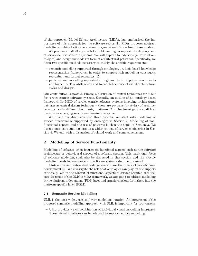
of the approach, Model-Driven Architecture (MDA), has emphasised the im-portance of this approach for the software sector [1]. MDA proposes abstractmodelling combined with the automatic generation of code from these models.
We propose an MDD approach for SOA, aiming to support the developmentof service-centric software systems. We will explore foundations (in form of on-tologies) and design methods (in form of architectural patterns). Specifically, wedeem two specific methods necessary to satisfy the specific requirements:
– semantic modelling supported through ontologies, i.e. logic-based knowledgerepresentation frameworks, in order to support rich modelling constructs,reasoning, and formal semantics [15].
– pattern-based modelling supported through architectural patterns in order toadd higher levels of abstraction and to enable the reuse of useful architecturalstyles and designs.
Our contribution is twofold. Firstly, a discussion of central techniques for MDDfor service-centric software systems. Secondly, an outline of an ontology-basedframework for MDD of service-centric software systems involving architecturalpatterns as central design technique – these are patterns (or styles) of architec-tures, typically different from design patterns [24]. Our investigation shall leadtowards an emerging service engineering discipline.
We divide our discussion into three aspects. We start with modelling ofservice functionality supported by ontologies in Section 2. Modelling of non-functional aspects and the use of patterns is then the topic of Section 3. Wediscuss ontologies and patterns in a wider context of service engineering in Sec-tion 4. We end with a discussion of related work and some conclusions.
2 Modelling of Service Functionality
Modelling of software often focuses on functional aspects such as the softwarearchitecture or behavioural aspects of a software system. This traditional focusof software modelling shall also be discussed in this section and the specificmodelling needs for service-centric software systems shall be discussed.
Abstraction and automated code generation are the pillars of model-drivendevelopment [4]. We investigate the role that ontologies can play for the supportof these pillars in the context of functional aspects of service-oriented architec-ture. In terms of the OMG’s MDA framework, we are going to address modellingat the platform-independent (PIM) layer and transformations form there into theplatform-specific layer (PSM).
2.1 Semantic Service Modelling
UML is the most widely used software modelling notation. An integration of theproposed semantic modelling approach with UML is important for two reasons:
– UML provides a rich combination of individual visual modelling languages.These visual interfaces can be adapted to support service modelling.
32

– A vast amount of UML models for a broad range of application contextsexist. Reusing and integrating these is almost a necessity.
UML is limited in particular in terms of the constraints on software systemsthat can be expressed. OCL, the Object Constraint Language, is a UML ex-tension that allows semantic constraints such as pre- and postconditions andinvariants for operations and classes to be expressed [17]. While a wide range ofpowerful logics have been available to support constraint formulation and reason-ing, the recent advent of the Semantic Web with its ontology-based foundationshave make ontologies a promising candidate for enhanced semantic modelling inthe context of the Web platform [16].
– Ontologies provide a logical language, for instance based on description logic[14], with its reasoning support.
– Ontology languages, such as OWL, are the knowledge representation lan-guages of the Web [16] that enable XML-based syntactical interoperabilityand knowledge sharing and exchange.
For these reasons, the semantic modelling of Web services is ideally supportedby ontologies, as the research focus on semantic Web services shows [7, 12]. Be-sides providing a rich semantic modelling notation – which can, as proposed, beaugmented by a UML-style interface – ontologies can support design activitiessuch as composition, and act as formal semantics for the overall model-drivendevelopment integrating modelling and transformations.
WSMO [10] and OWL-S [9] are the two predominant examples of service on-tologies. Service ontologies are ontologies to describe Web services, aiming to sup-port their semantics-based discovery in Web service registries. The Web ServiceProcess Ontology WSPO [13] is also a service ontology, but its focus is the sup-port of description and reasoning about service composition and service-basedarchitectural configuration. An important current development is the SemanticWeb Services Framework (SWSF), consisting of a language and an underlyingontology [21], which takes OWL-S work further. The FLOWS ontology in SWSFcomprises process modelling and is like WSPO suited to support semantic ser-vice modelling within the MDA context. While the early service ontologies havefocused on individual services and their properties – OWL-S and WSMO – morerecent attention has been paid to service process ontologies – SWSF and WSPO– which focus on the composition of services to form processes. A different type ofontology, supporting composition activities and the formulation of collaboratingservcies as processes, is needed for the composition aspect [8].
2.2 Service Composition
In order to support the development of service architectures, more than justdescription notations are needed. Specific activities such as service discovery orprocess composition need to be supported through anaysis and reasoning tech-niques [22]. We look here into ontology-based support for service composition.
33

login
<<postCondition>>result=balance(account)
balanceenquiry
moneytransfer
logout
<<preCondition>>true
<<postCondition>>vaild(sessionID)
<<preCondition>>valid(user,account)
<<postCondition>>not valid(sessionID)
<<preCondition>>vaild(sessionID) ∧
balance(account)>0
<<preCondition>>valid(sessionID)
<<postCondition>>balance =
balance@pre -amount<<decisionInput>>
choice
{user,account}
{account}
{account,destination,
amount}
{sessionID}
{sessionID}
{balance}
{void}
{void}
Fig. 1. Semantic Service Process Model based on UML Activity Diagrams.
Service composition is a logical composition where an abstract service processbased on individual services is assembled [6]. We have developed the WSPOcomposition ontology – Web Services Process Ontology – in order to supportthe semantically correct composition of services [13].
Ontologies in general consist of concepts that represent objects, process, etc.and relationships between these concepts. Services (and processes) in the WSPOontology are not represented as concepts, but as relationships denoting accessi-bility relations between states of a software system.
– Ontology concepts in this approach are states (pre- and poststates), param-eters (in- and out-parameters), and conditions (pre- and postconditions).
– Two forms of relationships are provided in the ontology. The services orprocesses themselves are called transitional relationships. Syntactical andsemantical descriptions here parameter objects (syntax) and conditions (se-mantics) are associated through descriptional relationships.
WSPO provides a standard template for service and service process description– applied in Fig. 1 to express a composite bank account process consisting ofoperations provided by services like ’balance enquiry’ or ’money transfer’. Thisapplication is based on four individual services, each described in terms of input,output, precondition, and postcondition. Syntactical parameter information inrelation to the individual activities – to be implemented through service opera-tions – and also semantical information such as pre-conditions are attached toeach activity as defined in the template. The following textual representationsummarises the syntactical aspects in a traditional IDL-style interface format:
application AccountProcessservices login (user:string, account:int) : ID
balance enquiry (account:int) : currencymoney transfer (account:int, destination:int, amount:currency) : void
34
logout (sessionID:ID) : voidprocess login; !( balance enquiry + money transfer ); logout
The services are composed to a process, here using the combinators sequence (;),iteration (!), and choice (+) in the textual representation above, which is alsovisualised in UML notation in Fig. 1.
WSPO can be distinguished from traditional service ontologies by two specificproperties. Firstly, based on an extension of description logics [14], it adds arelationship-based process sublanguage enabling process expressions based oniteration, sequential and parallel composition, and choice operators. Secondly,it adds data to processes in form of parameters that are introduced as constantprocess elements into the process sublanguage. This ontological representationin WSPO is actually an encoding of a simple dynamic logic (a logic of programs)in a description logic format [13], allowing us to avail of modal logic reasoningabout processes in this framework. For example, in order to implement a bankaccount process, an implementation for a money transfer service with inputparameter amount (assumed to be always positive) needs to be integrated. Forany given state, the process developer might require (using the balance enquiry)
service:preCondition rdfConstr="balance() > amount"service:postCondition rdfConstr="balance() = balance()@pre - amount"
which would be satisfied by a provided service
service:preCondition rdfConstr="balance() > 0"service:postCondition rdfConstr="balance() = balance()@pre - amount
and lastActivity = ’transfer’"
The provided service would weaken the required precondition assuming that thetransfer amount is always positive and strengthen the required postcondition asan additional result (lastActivity) is delivered by the provided service. Thismatching notion, which is important for service discovery support, is imple-mented in WSPO based on a refinement of the standard subsumption relationof description logics towards a consequence inference rule from dynamic logic.
We have chosen WSPO here instead of the SWSF. The more recent SWSFis an equally suitable service process ontology, providing actually a wider rangeof modelling feature, which would make it the better choice once sufficient toolsupport is available. For the moment, WSPO as a more focused and decidableontology is the better choice in terms of tractability of the approach.
2.3 Transformation and Code Generation
Automated code generation is one of the central objectives of MDD. Two typesof generation of code in service platform-specific languages are relevant here
– Executable code generation: in the context of SOA, code generation es-sentially means the generation of exectuable service processes. WS-BPEL
35

(BPEL, 2004) has emerged as the most widely accepted process executionlanguage for Web services. Within MDD, code generation is usually specifiedthrough transformation rules.
– Abstract description generation: a central element of SOA is service discoverybased on abstract service descriptions. OWL-S, WSMO, or SWSF would besuitable ontology frameworks that support description and discovery.
An overview of some of the transformation rules for a WSPO to WS-BPELtransformation to generate executable code is presented below. WSPO defines asimple process language that can be fully translated into WS-BPEL. BPEL pro-cess partners are the consumers and the different service providers – the WSPOspecification is already partitioned accordingly. The WSPO process combinatorscan also be mapped directly onto the BPEL flow combinators. The principles ofthis transformation can be characterised as follows:
– The WSPO process relationships can be mapped to BPEL processes.– For each process, a BPEL partner process (consumer and server) is created.– Each process expression is converted into BPEL-invoke activities at the client
side and BPEL-receive and -reply activities at the server side.– The process combinators ’;’, ’+’, ’ !’, and ’||’ are converted to the BPEL flow
combinators sequence, pick, while, and flow, respectively.
A schematic example in the declarative transformation language QVT shall il-lustrate these principles for WSPO-to-BPEL transformations1:
transformation WSPO_to_WS-BPEL (wspo : WSPO, bpel: WS-BPEL){top relation TransRelationship_to_Process
/* maps trans. relationships to processes */{checkonly domain wspo w:TransRel {name = pn}enforce domain bpel b:Process {name = pn}
}where {
RelExpr_to_ProcessExpr(w);}
relation RelExpr_to_ProcessExpr/* map each process expression recursively */
{domain wspo r:Relationship {e1 = e:LeftExpr {},e2 = e:RightExpr {},op = c:Combinator {}
1 Although its standardisation is not completed and no tool support is currently avail-able for the declarative specifications, QVT will be an essential tool for the imple-mentation of our approach in the near future.
36

}domain bpel p:Process {process = p:Process {left=e1, pr=op, right=e2},client = pe:ProcessExpr {invoke=op(e1,e2)},server = pe:ProcessExpr {receive=(op,e1,e2), reply=op(e1,e2)}
}when {CombinatorMapping(op) and ProcessPartnerCreation(p);
}where {RelExpr_to_ProcessExpr(e1) and RelExpr_to_ProcessExpr(e2);
}}
}
We do not present the WS-BPEL representation here, since with the exception ofsome reformulations of operators and the additional verbosity of the XML-basedformulation, the process itself is similar to the WSPO representation.
The second transformation and code generation context relates to servicedescription and discovery. The Web Services platform proposes a specific archi-tecture based on services, which can be located using abstract service informationprovided in service registries. The description of services – or service processesmade available as a single service - ideally in semantical format is therefore ofcentral importance. Information represented in the process model and formalisedin the service process ontology can be mapped to a service ontology. This trans-formation would only be a mapping into a subset of these ontologies, since theycapture a wide range of functional and non-functional properties, whereas wehave focussed on architecture-specific properties in WSPO.
We chose WSMO as the target. An overview of the transformation rulesfrom WSPO to WSMO is outlined below. Some correspondences between thetwo ontology frameworks guide this transformation. WSPO input and outputelements correspond to WSMO message-exchange patterns, which are used inWSMO to express stimuli-response patterns of direct service invocations, andWSPO pre- and postconditions correspond to their WSMO counterparts.
– WSPO process relationships are mapped to WSMO service concept and fillmessageExchange and pre- and postCondition properties accordingly.
– WSPO in/out-objects are mapped to WSMO messageExchange descriptions.– WSPO pre- and postconditions are mapped onto their WSMO counterparts.
A QVT formulation would be similar to the WSPO-to-BPEL transformation.
2.4 Discussion
This section has demonstrated the role that ontologies can play in model-drivendevelopment of service-centric software systems. They can provide a semanticmodelling framework in particular for the Web platform due to the support of
37

ontologies through the Semantic Web initiative. They can act as a foundationallayer to define visual modelling languages, to support composition tasks, and toenable automated transformations.
While we have discussed the application of ontologies for functional aspectsof software systems specification such as pre- and postconditions, their scopestretches further to also include non-functional aspects such as general descrip-tions, cost models, security requirememts, etc. . Non-functional aspects shall beaddressed in depth in the next section.
3 Modelling of Non-Functional Service Aspects
The deployment model of services in general and Web services in particularis based on the idea of service provider and service consumer being businesspartners. This constellation requires contracts to be set up, based on service-level agreements (SLAs). While of course functional characteristic of services arevital elements in these SLAs, non-functional aspects – ranging from availabilityand performance guarantees to costing aspects – are equally important and needto be captured in SLAs to clearly state the quality-of-service (QoS) obligationsand expectations of provider and consumer.
This discussion will show that ontologies are an adequate modelling notation,but that additional techniques are needed to address modelling, in particular iffunctional and non-functional aspects are integrated. We will introduce distribu-tion patterns, again at the architectural level, to provide a framework for higherlevels of abstraction beyond the service process composition [26]. These patternswill add a widely used method centering around the notion of reuse of abstractarchitectural designs and models to semantic modelling. A quality dimension isadded through quality attributes associated to these distribution patterns.
3.1 Distribution and Service Topology
Ontologies, the focus of the previous section, can deal with the abstract specifi-cation of QoS properties by providing an adequate vocabulary based on a varietyof relationships. A mere statement of required QoS properties is therefore oftennot sufficient to actually guarantee these properties. However, there are links be-tween functionally-oriented models and QoS properties. We look at distributionproperties of service-centric software systems to illustrate this.
Distribution, i.e. the consideration of the location of services in a complexsystem, affects qualities of the software systems such as reliability, availability,and performance. We use the term service topology to refer to the modelling ofservice compositions as collaborating entities under explicit consideration of thedistribution characteristics.
3.2 Service Topology Modelling
Based on experience with the design and implementation of service-centric soft-ware systems, a number of standard architectural configurations have emerged
38

[25, 27, 29, 31]. These include centralised configurations such as the Hub-and-Spoke or decentralised ones such as Peer-to-Peer architectures. These standardconfigurations can be abstracted into architecture-lavel distribution patterns forthe SOA platform.
The goal is to enable the generation of architecturally flexible Web servicecompositions, whose Quality of Service (QoS) characteristics can be evaluatedand altered at design time. Distribution pattern modelling expresses how thecomposed system is to be deployed from the architectural perspective [18]. Hav-ing the ability to model, and thus alter the distribution pattern, allows an enter-prise to configure its systems as they evolve, and to meet varying non-functionalrequirements.
There is a subtle difference between two of the modeling aspects within aWeb service composition, namely workflows and distribution patterns. Both as-pects refer to the high level cooperation of components, termed a collaboration,to achieve some compound novel task. We consider workflows as compositionalorchestrations, whereby the internal and external messages to and from servicesare modelled. In contrast, distribution patterns are considered compositionalchoreographies, where only the external messages flow between services is mod-elled. Consequently the control flow between services are considered orthogonal.As such, a choreography can express how a system would be deployed. Theinternal workflows of these services are not modelled here, as there are manyapproaches to modelling the internals of such services.
3.3 Modelling Process and Transformation
This component of our framework comprises a catalog of distribution patterns,which may be applied by software architects to Web service compositions [18].Distribution patterns express how a composed system is to be assembled andsubsequently deployed. Each of the patterns in the catalog has associated Qual-ity of Service (QoS) characteristics, exhibited during execution of Web servicecompositions. The catalog enumerates the QoS characteristics of each of thepatterns, enabling the architect to choose a pattern appropriate to the non func-tional requirements of a given composition.
The patterns are split into three categories, core patterns, auxiliary patternsand complex patterns. Core patterns represent the simplest distribution patternsmost commonly observed in Web service compositions. Auxiliary patterns arepatterns which can be combined with core patterns to improve a given QoScharacteristic of a core pattern, the resultant pattern is a complex pattern. Thiscatalog assists software architects in choosing a distribution pattern for a givenapplication context. The catalog is outlined briefly below:
– Core Patterns: Centralised, Decentralised– Auxiliary Patterns: Ring– Complex Patterns: Hierarchical, Ring + Centralised, Centralised + Decen-
tralised, Ring + Decentralised
39

We describe one pattern to illustrate distribution patterns and their QoS rele-vance. The Centralised pattern, or Hub-and-Spoke pattern, manages the compo-sition from a single location, normally the participant initiating the composition.Here is the service choreography:
application Centralisedservices Hub ( in : inType) : outType
Spoke1 ( . . . ) : . . .. . .Spoken ( . . . ) : . . .
process Hub ||D ( Spoke1 || . . . || Spoken )
The composition controller (the hub) is located externally from the serviceparticipants to be composed (the spokes), indicated through the distributionannotation at the parallel composition operator. Spokes would internally invokethe Hub using the given Hub interface. The external spoke interfaces are notrelevant here. This is the most popular and usually default distribution configu-ration for service compositions. The advantages of the pattern in terms of QoSaspects are:
– Composition is easily maintainable, as composition logic is all contained ata single participant, the central hub.
– Low deployment overhead as only the hub manages the composition.– Composition can consume participant services that are externally controlled.
Web service technology enables the reuse of existing services.– The spokes require no modifications to take part in the composition. Web
service technology enables interoperability.
The main disadvantages are:
– A single point of failure at the hub provides for poor reliability/availability.– A communication bottleneck at the hub restricts scalability. SOAP messages
have considerable overhead for message deserialisation and serialisation.– The high number of messages between hub and spokes is sub-optimal. SOAP
messages are often verbose resulting in poor performance for Web services.– Poor autonomy in that the input and output values of each participant can
be read by the central hub.
A distribution pattern language DPL provides the constructs for the internalrepresentation of a distribution pattern. The DPL, which similarly to WSPOhas a UML interface based on activity diagrams, provides:
– control flow: information about the nodes and edges that define the controlflow structure, on which interactions between individual services take place.
– data flow: information about which data is flowing in which direction in aninteraction between services.
DPL is a high-level service process modelling language that provides the foun-dations for pattern-based service architecture.
40

3.4 Discussion
While we have looked at architectural patterns to model the functional sidein the previous section, i.e. the structural and behavioural aspects of software,we have focused here on their potential in the context of non-functional prop-erties. Distribution patterns imply non-functional properties of service-centricsoftware systems. The choice of these patterns in particular determines perfor-mance, availability, and reliability charateristics of the software system itself.
4 A Service Engineering Perspective
Issues arising from the cooperation between organisations and the integrationof systems across organisations leads to another couple of issues relevant to ourdiscussion of ontologies and patterns for service-centric software engineering.This discussion of a wider context helps us to determine the potential, but alsothe challenges for the use of ontologies and patterns.
4.1 Cooperation
The cooperation between service providers and consumers is necessary for service-oriented computing. This requires at least interoperability of formats of all ar-tifacts involved, in particular for models. Contracts stating service-level agree-ments are the actual documents, which might refer to additional documents andmodels internally. Ontologies have the potential to provide a common vocabu-lary that would allow the automated processing of these contracts. The wideraim within a service-centric software engineering discipline is an integrated valuechain for software services that brings together all participants in the productionprocess – for instance through interoperable deployment infrastructures, but alsothrough contract and model exchange.
4.2 Trust
Trust is a central problem for collaborating partners that are initially often un-known to each other. In the context of automated service compositions, detailedmodel-based contracts can capture the obligations and expectations in terms offunctional and QoS service properties, but do not suffice on their own. Interop-erability is an enabler of integrated value chains, but only trust will make thisbusiness scenario work ultimately.
At the core of trust mechanisms are composition and description techniques,for instance our ontology-based modelling techniques. Quality-of-service andother non-functional properties broaden the overall focus without losing thecomposition activity at the core.
The certification of services is the central trust mechanism. A certificationinfrastructure needs to be added to allow in particular consumers to trust theirservice providers. Certification needs to ensure in the service composition context
41

more than the authenticity of the provider; it needs to ensure service properties.This is another potential use of, but also a technical challenge for ontology tech-nology. Models of the various aspects play a central role here as the foundationsof contracts, which can form the basis of a certificate. For instance, the proofsof properties resulting from ontological reasoning about service properties andservice compositions can be included in these certificates.
Trust is an important non-functional consideration that effects the businesscontext of service composition and provision. The richness of our ontologicalmodelling framework in terms of models and reliable patterns, however, makestrust also an opportunity that might succeed for this context.
4.3 Environment and Standardisation
The activities by standardisation bodies in the software technology context,such as the OMG or the W3C, indicate two directions for model-driven ser-vice engineering. The OMG has proposed MDA to address code generation andmaintenance, which can act as a framework for a development approach forservice-centric software systems.
The integration of models and descriptions is the first challenge. One stan-dard is expected to be central in this endeavour. The Ontology Definition Meta-model ODM is a MOF-based integration format for ontologies and UML models,currently standardised by the OMG [11]. The ODM metamodel can support se-mantic services, process composition, and UML model reuse. It allows the overallintegration of semantic descriptions and models. ODM is complemented by theW3C’s proposal of OWL as the Semantic Web ontology language and ODA asan ontology-based software development approach.
A second challenge arises from the business perspective on services. Thiswould include in the services context in particular workflow and business pro-cess modelling as part of a business process engineering stage and semantic inte-gration. Currently, this aspect with a focus on business modelling and analysisis receiving some attention. The OMG-supported Business Process ModellingNotation BPMN is an example. MDA, for instance, provides only a framework,but not enough support for the consistent mapping of business processes ontothe platform layer. The use of ontologies for semantic integration and patternsto provide an abstraction and design technique across the stages would improvethis endeavour.
5 Related Work
Some approaches have started exploiting the connection between ontologies –in particular OWL – and MDA. In [19], an MDA-based ontology architectureis defined. This architecture includes aspects of an ontology metamodel and aUML profile for ontologies. The work by [19] and the OMG [1, 11], however, needsto be carried further to address the ontology-based modelling and reasoning of
42

service-based architectures. In particular, the Web Services architecture needsto be addressed in the context of Web-based ontology technology.
Grønmo et.al. [20] introduce – based on ideas from [19] – an approach similarto ours. Starting with a UML profile based on activity diagrams, services aremodelled. These models are then translated into OWL-S. Although the paperdiscusses process composition, this aspect is not detailed. We have built on [20]in this respect by considering process compositions in the UML profile and bymapping into a service process ontology that focusses on providing explicit sup-port for service composition. In comparison to UML/OCL approaches, ontologiesenable full-scale logic support and also the possibilty to share representationsdue to their grounding in OWL.
Since software architecture is the overall context of our investigation, archi-tectural description languages (ADLs) shall briefly be discussed. For instance,Darwin [28] is a π-calculus-based ADL. Darwin focuses on component-orienteddevelopment, addressing behaviour and interfaces. Restrictions based on thedeclarative nature of Darwin make it rather unsuitable for the design of service-based architectures, where both binding and unbinding on demand are requiredfeatures. With the support for composition and abstraction of architectural con-figurations service composition ontologies and distribution patterns would con-stitute an essential part of an ADL.
The notion of patterns has recently been discussed in the context of Webservice architectures [25, 29]. In [29, 27], collections of workflow patterns arecompiled. We have based our catalog on these collections. Grønmo et al. [30]consider the modelling and building of compositions from existing Web servicesusing MDA, based on [31]. The authors consider two modelling aspects, service(interface and operations) and workflow models (control and data flow concerns).Their modelling effort begins with the transformation of WSDL documents toUML, followed by the creation of a workflow engine-independent UML activitydiagram, which drives the generation of an executable composition.
6 Conclusions
A new architectural paradigm such as service-oriented architecture (SOA) re-quires adequate methodological support for design and maintenance. While anunderlying deployment platform exists in the form of the Web services platform,an engineering methodology and techniques are still largely missing. The im-portance of modelling for SOA has been recognised – and has resulted in thedevelopment of Model-Driven Architecture (MDA) as an approach to supportthe design of service-centric software systems. We have focussed on pattern-basedsemantic modelling of service architectures. These are two architectural aspects– semantic service description and pattern- and process-based architectural con-figuration – that can complement the MDA approach.
Ontology and Semantic Web technologies provide semantic strength for themodelling framework, necessary for a distributed and inter-organisational en-vironment. A central element of our modelling method is a service ontology
43

tailored to support service composition and transformation. An ontology-basedtechnique is here beneficial for the following reasons. Firstly, ontologies define arigourous, logic-based semantic modelling and reasoning framework thats sup-port architectural design activities for services. Secondly, ontologies provides aknowledge integration and interoperability platform for multi-source semanticservice-based software systems. Our aim here was to demonstrate the suitabilityof ontologies for this environment – for both WSPO to support architecturalissues but also for WSMO here to support service discovery. We have integratedthis service composition ontology with a pattern-based architecture modellingtechnique integrating visual UML-based modelling, transformation, ontology-based reasoning, and code generation.
We see our investigation as a step towards a service engineering discipline.Service engineering deals with process and integration issues. While we havefocused on service composition and integration, data integration is an equallyimportant that needs to be investigated further in this context. We interprethere a notion of service engineering as a wider process, covering a number ofvalue chain stages. The software value chain that we have referred to earlierstructures service engineering. It is a classical top-down model that needs tobe augmented further. System evolution adds another dimension of importancefor a service engineering discipline. Re-engineering and migration need to beintegrated. Legacy systems can be integrated into service-oriented architecturesusing software re-engineering and architecture transformation.
References
1. Object Management Group. MDA Model-Driven Architecture Guide V1.0.1. OMG,2003.
2. L. Bass, P. Clements, and R. Kazman. Software Architecture in Practice (2ndEdition). SEI Series in Software Engineering. Addison-Wesley, 2003.
3. G. Alonso, F. Casati, H. Kuno, and V. Machiraju. Web Services – Concepts,Architectures and Applications. Springer-Verlag, 2004.
4. B. Selic. The Pragmatics of Model-Driven Development, IEEE Software, 20(5):19–25, 2003.
5. World Wide Web Consortium. Web Services Architecture.http://www.w3.org/TR/ws-arch, 2006. (visited 28/02/2006).
6. C. Peltz. Web Service orchestration and choreography: a look at WSCI andBPEL4WS. Web Services Journal, 3(7), 2003.
7. S. McIlraith and D. Martin. Bringing Semantics to Web Services. IEEE IntelligentSystems, 18(1):90–93, 2003.
8. J. Rao, P. Kungas, and M. Matskin. Logic-Based Web Services Composition: FromService Description to Process Model. In International Conference on Web ServicesICWS 2004, pages 446–453. IEEE Press, 2004.
9. DAML-S Coalition. DAML-S: Web Services Description for the Semantic Web.In I. Horrocks and J. Hendler, editors, Proc. First International Semantic WebConference ISWC 2002, LNCS 2342, pages 279–291. Springer-Verlag, 2002.
10. R. Lara, M. Stollberg, A. Polleres, C. Feier, C. Bussler, and D. Fensel. Web ServiceModeling Ontology. Applied Ontology, 1(1):77–106, 2005.
44

11. Object Management Group. Ontology Definition Metamodel - Request For Proposal(OMG Document: as/2003-03-40). OMG, 2003.
12. C. Pahl. Layered Ontological Modelling for Web Service-oriented Model-DrivenArchitecture. In European Conference on Model-Driven Architecture ECMDA2005.Springer LNCS Series, 2005.
13. C. Pahl. An Ontology for Software Component Matching. International Journal onSoftware Tools for Technology Transfer (STTT), Special Edition on Component-based Systems Engineering, 7, 2007 (in press).
14. F. Baader, D. McGuiness, D. Nardi, and P.P. Schneider, editors. The DescriptionLogic Handbook. Cambridge University Press, 2003.
15. M.C. Daconta, L.J. Obrst, and K.T. Smith. The Semantic Web. Wiley, 2003.16. W3C Semantic Web Activity. Semantic Web Activity Statement, 2004.
http://www.w3.org/2001/sw.17. J.B. Warmer and A.G. Kleppe. The Object Constraint Language – Precise Modeling
With UML. Addison-Wesley, 2003. (2nd Edition).18. R. Barrett, L. M. Patcas, J. Murphy, and C. Pahl. Model Driven Distribution Pat-
tern Design for Dynamic Web Service Compositions. In International Conferenceon Web Engineering ICWE06. Palo Alto, US. ACM Press, 2006.
19. D. Djuric. MDA-based Ontology Infrastructure. Computer Science and Informa-tion Systems (ComSIS), 1(1):91–116, 2004.
20. R. Grønmo, M.C. Jaeger, and H. Hoff. Transformations between UML and OWL-S. In A. Hartman and D. Kreische, editors, Proc. Model-Driven Architecture –Foundations and Applications, pages 269–283. Springer-Verlag, LNCS 3748, 2005.
21. Semantic Web Services Language (SWSL) Committee. Semantic Web ServicesFramework (SWSF). http://www.daml.org/services/swsf/1.0/, 2006.
22. B.-H. Schlingloff, A. Martens and K. Schmidt. Modeling and Model Checking WebServices. Electronic Notes in Theoretical Computer Science: Issue on Logic andCommunication in Multi-Agent Systems, 126:3-26. 2005.
23. R. Dijkman and M. Dumas. Service-oriented Design: A Multi-viewpoint Approach.Intl. Journal of Cooperative Information Systems, 13(4):337-368. 2004.
24. E. Gamma, R. Helm, R. Johnson, and J. Vlissides. Design Patterns: Elements ofReusable Design. Addison Wesley, 1995.
25. N.Y. Topaloglu and R. Capilla. Modeling the Variability of Web Services from aPattern Point of View. In L.J. Zhang and M. Jeckle, editors, Proc. European Conf.on Web Services ECOWS’04, pages 128–138. Springer-Verlag, LNCS 3250, 2004.
26. C. Pahl and R. Barrett. Towards a Re-engineering Method for Web Services Ar-chitectures. In Proc. 3rd Nordic Conference on Web Services NCWS’04. 2004.
27. W.M.P. van der Aalst, B. Kiepuszewski A.H.M. ter Hofstede, and A.P. Barros.Workflow Patterns. Distributed and Parallel Databases, 14:5–51, 2003.
28. J. Magee, N. Dulay, S. Eisenbach, and J. Kramer. Specifying Distributed SoftwareArchitectures. In W. Schafer and P. Botella, editors, Proc. 5th European SoftwareEngineering Conf. (ESEC 95), Springer LNCS 989, pages 137–153. 1995.
29. M. Vasko and S. Duskar. An Analysis of Web Services Flow Patterns in Col-laxa. In L.J. Zhang and M. Jeckle, editors, Proc. European Conf. on Web ServicesECOWS’04, pages 1–14. Springer LNCS 3250, 2004.
30. D. Skogan, R. Grønmo and I. Solheim. Web Service Composition in UML. InProc. 8th International IEEE Enterprise Distributed Object Computing Conference(EDOC), pages 4757.2004.
31. S. Thone, R. Depke and G. Engels. Process-Oriented, Flexible Composition of WebServices with UML. In Proc. Joint Workshop on Conceptual Modeling Approachesfor e-Business (eCOMO 2002). 2002.
45

Architectural Decision Models as Micro-Methodology for Service-Oriented Analysis and Design
Olaf Zimmermann1 Jana Koehler1 Frank Leymann2
1 IBM Research GmbH Zurich Research Laboratory, Säumerstrasse 4, 8803 Rüschlikon, Switzerland
{olz,koe}@zurich.ibm.com 2 Universität Stuttgart, Institute of Architecture of Application Systems
Universitätsstraße 38, 70569 Stuttgart, Germany [email protected]
Abstract. During the construction of service-oriented architectures, service modelers concern themselves with the characteristics of good services and how such services can be designed. For instance, they look for advice regarding interface granularity and criteria to assess whether existing software assets are fit for reuse in service-oriented environments. There are no straightforward an-swers to such questions – service identification, specification and realization techniques are required. Service identification and specification are well cove-red by existing methodologies; for service realization, architectural decision models can be leveraged. At present, the construction of architectural decision models is an education- and labor-intensive undertaking; if such models exist at all, they often are isolated from other artifacts. In this paper, we propose a new engineering approach to service modeling that leverages reusable architectural decision models as its central service realization concept. We outline a mul-ti-level decision tree and position it as a prescriptive service realization methodology for three engagement types observed in practice. The benefits of service engineering with reusable architectural decision models are semi-automatic decision identification in analysis models, improved decision making quality, and better decision enforcement and risk mitigation capabilities.
Keywords: Architectural decisions, methodology, MDA, service design, SOA
1 Introduction
During the early stages of the evolution of Service-Oriented Architecture (SOA) as an architectural style, Grady Booch stated that “the fundamentals of engineering like good abstractions, good separation of concerns never go out of style”, but he also pointed out that “there are real opportunities to raise the level of abstraction again” [6]. When designing large-scale enterprise applications, this raise of abstraction level concerns the business domains a company deals with, as well as already existing Information Technology (IT) assets. Business-aligned software services organized into an enterprise-scale SOA reside on this increased level of abstraction. However, implemented software services still have to meet domain-specific Non-Functional
46

Requirements (NFRs) and standard software quality criteria [11]; old and new design challenges arise, e.g., designing services for multiple invocation contexts.
Therefore, there is more to constructing service abstractions of quality and style than identifying abstract software services, specifying them with technical interface contracts such as Web Service Description Language (WSDL) port types, and then applying WSDL-to-code transformation wizards. No single SOA fits all purposes; many architecture design issues and tradeoffs arise. There are no straightforward answers to the service modeling questions that arise – service identification, specification, and realization techniques are required.
For service identification and specification, several techniques such as Service-Oriented Modeling and Architecture (SOMA) [2] and others [9][24] exist; for service realization, architectural decisions [26] are a promising complementary abstraction. In [34], we defined architectural decisions as “conscious design decisions concerning a software system as a whole, or one or more of its core components. These decisions determine the non-functional characteristics and quality factors of the system”. Architectural decision modeling is an emerging field in software architecture research [18]. Unlike other approaches to document software, architectural decision models fo-cus on the expert knowledge motivating certain designs rather than the resulting de-signs themselves. Model elements present architecture alternatives with pros and cons, as well as known uses, and they also capture the rationale behind and the justification for many different types of decisions.
In SOA construction, service realization decisions include strategic concerns such as technology and product selections (e.g., composition technology, workflow engine). Finer-grained modeling tasks such as finding the right service interface gra-nularity (operation-to-service grouping, message signature shaping) form a second decision category. Numerous decisions deal with non-functional aspects such as operation transactionality (business-level compensation, system transactions). For instance, imagine a scenario in which a situational data warehouse application on a Personal Computer, an e-commerce software package on a Linux workstation and a custom developed inventory management solution on a central mainframe computer have to be integrated. Such systems typically differ in the way they manage human user access, balance load, synchronize concurrent requests, persist data, protect themselves against security threats, and so forth – their software architectures are different. When being integrated in an SOA, these systems provide services to each other. Even if the service interfaces can be specified in an abstract, business-driven and technology-independent way, the mapping of the abstract interfaces to implementation components during service realization differs substantially in the three outlined environments. As a consequence, the service realization decisions for the three systems differ. For example, using a workflow engine might not be possible for the situational application, the software package might impose interface granularity constraints, and the mainframe might realize its own transaction monitor.
In this paper, we propose an engineering approach to service modeling. We treat service realization decisions as first-class entities that guide the service modeler through the design process. We capture these decisions in machine-readable models. This SOA knowledge is organized in a reusable multi-level SOA decision tree, including a conceptual, a technology, and an asset level. The tree organization follows Model-Driven Architecture (MDA) principles, separating rapidly changing platform-
47

specific concerns from longer-lasting platform-independent decisions. Architecture alternatives in the conceptual level are expressed as SOA patterns. An underlying meta model facilitates automation of service realization decision identification, making, and enforcement: Meta model instances (models) can be created from re-quirements models and reference architectures, and shared across project boundaries. The meta model also enables decision dependency modeling and tree pruning – making one decision has an impact on many other decisions. For example, a workflow engine is only required if process-enabled service composition has been de-cided for. In the resulting process-enabled SOA [15], transaction management settings must be defined consistently for various architecture elements such as process invoke activities, service operations and database drivers.
Explicit dependency modeling has another key advantage: the decision tree can serve as a micro-methodology during service design, operating on a more detailed le-vel of abstraction than general purpose methods such as the Rational Unified Process (RUP) [16] and the service modeling approaches described in the literature [2][9][24]. Our approach is complementary to these assets; e.g., the decisions can be organized along the RUP phases such as inception, elaboration and construction.
The remainder of this paper is organized in the following way: Section 2 derives the problem statement motivating our work from state of the art and the practice. Sec-tion 3 then presents structure and content of our SOA decision tree. Section 4 explains how this SOA decision tree can be used as a micro-methodology for SOA. Section 5 presents related work; Section 6 discusses the benefits of our approach and how we applied it in practice. Section 7 concludes and gives an outlook to future work.
2 The Service Modeling Problem
Methods like SOMA define the tasks within the service modeling process, SOA patterns present proven solution designs. However, the detailed technical design steps between business-level service identification and pattern instantiation on implementa-tion and runtime platforms still are covered rudimentarily only. Detailed modeling guidance leading to a prescriptive modeling algorithm is desired that helps answering the following question:
How to design and develop “good”, business-aligned service abstractions from analysis-level business process models and technical requirements?
As a corollary, the question arises how good services can be characterized. For example, what does business alignment mean from a technical standpoint, and what is the appropriate service granularity in a certain domain context? When trying to answer these questions, development projects start from vaguely articulated requirements, documented as high-level business process and/or use case models created by business analysts. In many cases, these models are defined informally or semi-formally only. However, eventually formal service descriptions have to be defined so that the realized services can be deployed to some IT infrastructure such as an application server or transaction monitor. We jointly refer to these issues as service modeling or Service-Oriented Analysis and Design (SOAD) [35]. Currently, these
48

issues are among the most frequently discussed topics in the industry and academia; we have not participated in a single SOA effort yet in which such service modeling aspects have not been a major concern.
Elements from several existing service modeling methodologies and techniques served us well when dealing with these issues. For example, SOMA covers top-down service identification in business process models and other business analysis artifacts. Service specification typically is also addressed well [13]. However, we noticed a gap between these two steps and detailed technical service realization aspects encountered on SOA construction projects. Existing patterns and general purpose method exten-sions are informative and educational, but often too coarse grained and incomplete. For example, advice regarding service-enablement of existing legacy systems ty-pically is weak, and transaction management is not covered in detail. Technology and vendor recommendations (often called “best practices”) are not integrated sufficiently, often causing quality problems and unnecessary duplication of efforts.
3 An Architectural Decision Model for SOA Construction
The actors involved in SOA construction are business analysts, service architects, and service developers. When Model-Driven Architecture (MDA) concepts are applied, these actors create a Platform-Independent Model (PIM) of the design based on a Computing-Independent Model (CIM) of requirements analysis results. They trans-form the PIM into one or more Platform-Specific Models (PSMs) and eventually into code. Therefore, it is natural to organize the architectural decision models according to MDA principles as well, applying principles such as layering and separation of concerns. Therefore, we propose three levels of decision model refinement, the con-ceptual, the technology, and the asset level. In addition, we see a need for an over-arching executive level, comprising of decisions of strategic relevance. Executive de-cisions impact the project as a whole [18]. They influence all other decisions.
To harvest already gained knowledge, we synthesized an initial SOA decision tree from our own project experience [33][36] and the literature [10][15]. Each decision node describes a single, concrete design issue. We describe the decision nodes according to the following informal representation of an underlying meta model [26]:
• Decision name and unique identifier. • Problem statement, either in question form or a single paragraph. • Scope of the decision, linking the decision model to design model elements. • Decision drivers, a list of key NFRs and software quality factors driving the
design; the pattern community use the term forces synonymously. • Architecture alternatives listing the available design options with their pros,
cons, and known uses. On the conceptual level, these are architectural pat-terns. On the technology level, they represent technical choices such as pro-tocol and design pattern selections; the asset level is concerned with open source and commercial product selection and configuration.
• References linking in literature such as short overviews, in depth tutorials. • Recommendation, depending on the decision type either a simple “do/do not”
rule of thumb, a weighted mapping of forces to alternatives, or a pointer to
49

more complex analysis process to be performed outside of the decision mo-del. An example for a simple rule of thumb is a commonly agreed best prac-tice: for example, WS-I recommends document/literal as SOAP communica-tion style and bans rpc/encoded [29]. For the design of transaction manage-ment boundaries on the other hand, no simple recommendation can be given; a more sophisticated algorithm capturing decision making heuristics and pro-ven alternatives as patterns is required. Decision drivers include business semantics, fault handling and resource protection needs, and NFRs.
• Lifecycle management information such as decision owner, project phase, validity timestamp, modification log, and decision enforcement.
• Outcome and justification of made decisions per decision instance. We have captured 130 such SOA decisions so far. Table 1 lists selected ones from
all four levels of abstraction introduced above, including their scope attribute and some of the alternatives available. The decision naming indicates dependencies, e.g., between the various decisions dealing with transactions.
Table 1. Excerpt from initial SOA decision tree
Tree level Decision node (scope) Alternatives Executive Platform/language/tool preferences (global) e.g. J2EE or LAMP Conceptual Service composition technology (process) Workflow vs. custom code (PIM) Transaction management strategy (process) System transaction vs.
business transaction Transaction management pattern (process) None vs. single transaction
vs. several transactions Transaction attribute (operation) None vs. new vs. join [31] Message exchange pattern (operation) Request-reply vs. one way In and out message breadth (operation) Single vs. multiple parts In and out message depth (operation) Flat vs. nested payload Technology (PIM/PSM)
Workflow language (process) Business Process Execution Language (BPEL) vs. other
Service container (service) SCA vs. J2EE vs. CORBA vs. .NET vs. other
Java service provider type (service) EJB vs. plain Java object SCA transaction qualifiers (operation) See SCE specifications [21] EJB transaction attribute (operation) Defined in EJB specification Message exchange style and format (operation) WS-*/SOAP vs.
REST/JSON vs. other Transport protocol binding (operation) HTTP vs. reliable messaging SOAP communication style (operation) Document/literal vs.
rpc/literal vs. rpc/encoded Asset (PSM) Workflow engine (process) Vendor or open source (IBM
WebSphere Process Server, ActiveBPEL, etc.)
SOAP message exchange engine (service) e.g. Apache Axis, Codehaus XFire, vendor engines such as IBM WebSphere engine
Service provider sourcing (service) Buy, build, adapt
50

The generic service granularity discussion leads to several decisions dealing with in and out message signature design, e.g. single vs. multiple message parts and flat vs. deeply nested payload (e.g., XML documents). On the technology level, there is a transport protocol binding decision with service operation scope – SOAP/HTTP or reliable messaging are the alternatives. About 40 other service operation realization decisions exist. One of about 20 process realization decisions is the choice of work-flow language, e.g. Business Process Execution Language (BPEL) [20]. The service container decision is closely related; BPEL can only be used if supported by the selected container, for example Service Component Architecture (SCA) [21].
Other decisions not shown in the table deal with security: cryptographic algorithms as means of integrity preservation are available on the transport and on the messaging layer. Message-level XML and Web services security or transport-level HTTPS/SSL are two of the available candidate assets.
4 The SOA Decision Tree as SOA Micro-Methodology
Once the various SOA decisions have been captured in the tree, and the decision dependencies have been modeled explicitly, the decision model can guide the practitioner through the design process. This is a SOA domain-specific method engineering approach, which aims to provide finer grained guidance than traditional artifact- and activity workflow-centric methodologies. The individual SOA decision is the central metaphor. Figure 1 shows selected decision topics and atomic decisions on five levels of abstraction, and illustrates the guiding role of the SOA decision tree.1
Asset Decisions (PSM)
Technology Design Decisions (PIM/PSM)
Conceptual Design Decisions (PIM)
Business Analysis Decisions (CIM)
Executive Decisions
<Service Modeling Method?> <Platform/Language?>
<Architectural Style?>
<Reference Architecture?>
<BPM Notation?> <BPM Tooling?>
<Technical Annotations?><Control Flow Design?>
<BPM Principles?> <Reference Model?>
<Data Flow Design?>
<Design Notation?>
<SOAP Runtime?>
{Process Realization Decisions?} {Service Realization Decisions?}
<CIM-to-PIM Mapping?>
<Buy, Build, Adapt?>
<Provider Type?><Service Container?><Workflow Language?>
<Service Registry?>
<Workflow Engine?>{Infrastructure Decisions?}
<Go/No Go?>
{Governance Decisions?}
<Atomic Decision?>
{Decision Topic?}
Fig. 1. SOA decision tree in guiding role (micro-methodology)
1 In line with the design decision literature, we refer to the SOA knowledge structure as a tree;
if in the formal sense it actually is a directed, not necessarily acyclic, graph.
51

Atomic decisions such as <ReferenceArchitecture?> appear in paired lower/greater-than signs. Decisions can be grouped into decision topics, which are embedded in curly braces. For example, topic area {Process Realization Decisions?} contains the pro-cess-scoped decisions that Table 1 assigned to the conceptual level. The selection of a <ServiceCompositionTechnology?> is an example.
Section 3 introduced the global executive decisions. In Figure 1, we also added business analysis decisions as another level of our micro-methodology. This level deals with decisions about the various Business Process Modeling (BPM) notations, tools, and techniques. While our main focus is technical service realization, we show this layer here to illustrate that our micro-methodology can work with different busi-ness modeling approaches, accepting the output of them as analysis input to the tech-nical design.
The vertical arrow does not imply that our micro-methodology is a strict top-down waterfall process; the ability to backtrack and revisit higher-level decisions because of feedback from the lower layers is a key concept in our approach. For example, a certain asset might not support a pattern selected on the conceptual level.
A topic area on the asset decisions level is {Infrastructure Decisions?}: Once the logi-cal design has reached a reasonable level of detail, the physical layout of the solution can be designed, including service deployment onto hardware, and network topology layout. Naturally, the detailed decisions in this group depend on many decisions on higher levels. For example, if stateful services exist, a session handover concept is required, at least in clustered environments.
Navigating through the tree. We provide a single point of entry into our SOA deci-sion tree, a global project <Go/No Go?> decision. Having passed this entry point, executive decisions like selection of <Architectural Style?>, <Service Modeling Method?> and <Engagement Type?> are the next decisions that have to be made. The outcome of these decisions defines the detailed path through the tree. So far, we have predefined the three ways through the tree for three engagement types, which are roughly equiva-lent to the maturity levels in the Service Integration Maturity Model (SIMM) in [3] and the stages in [15].
Web services enablement of a single component to achieve cross-platform inter-operability is a simple engagement type with many known uses, but limited strategic importance. Therefore, many executive decisions, e.g. regarding governance and ser-vice lifecycle management, are not required and can be removed from the tree. About 40 technical decisions remain to be taken per service.
A second, emerging engagement type is the introduction of a service choreography layer implementing an end-to-end business process. Such engagements address increased pressure from business in the areas of operational efficiency. For example, a process might have to complete within 24 hours. Enforcing such a business rule re-quires active process instance tracking, which can be achieved by workflow technolo-gy. This engagement type is a superset of the Web service enablement; decisions about BPEL usage also have to be made in this engagement type. The scenario from Section 1 is an example; traversing all process and service realization decisions inclu-ding those in Table 1 comprises a single iteration through our micro-methodology.
52

Enterprise-wide SOA enablement requires a full traversal of all tree levels. All de-cision nodes are applicable, and extensions are likely to be required. For example, an enterprise-wide <Service Registry?> must be selected; many governance decisions and more executive decisions have to be made.
MDA positioning. If MDA principles are followed, architectural decisions drive model transformations between the levels. Our conceptual level is a PIM, the techno-logy level has both PIM and PSM characteristics (depending on the viewpoint), and the asset level is a PSM. In a MDA transformation chain for SOA, decision models can be created and transformed just like design models. Figure 2 shows the resulting three-step MDA transformation chain:
To-Be BusinessAnalysis Decision Model
(CIM)
As-Is Design Model (PSM)
To-Be Decision Model (Assets, PSM)
Use Case (UC) 1-2: Service Architect
Use Case (UC) 1a: CIM->PIM(Top Down)
UC 1b: PSM->PIM(Bottom Up)
To-Be Decision Model (Conceptual, PIM)
As-Is Decision Model(Conceptual, Technology, Assets)
To-Be Decision Model (Technology, PIM/PSM)
UC 2: PIMxPIM->PIM/PSM
UC 3: PIM/PSM->PSM
UC 3: Service Developer
CIM – Computing Independent ModelPIM – Platform Independent ModelPSM – Platform Specific Model(OMG MDA Terminology)
Reference Architecture(incl. Reusable Decision Templates)
To-Be Design Model, Code (PIM, PIM/PSM, PSM)
Fig. 2. Architectural decision models in three-step model transformation chain for SOA
Step 1 consists of two transformations: Step 1a transforms to-be requirements business analysis decision models into an initial conceptual design decision model; Step 1b is a reverse transformation from as-is design models describing existing assets to a full instance of the SOA decision tree. Steps 2 and 3 correspond to the conceptual to technology and technology to asset level transitions in Figure 1. One pass through these steps comprises a single iteration in the micro-methodology.
Dependency management and tree pruning. Dependency propagation relationships exist between and within the levels. For instance, the decision to introduce a work-flow engine leads to the need for a user management subsystem, because the engine has to manage the status and progress of the process instance execution. This includes assigning activities to users. Users can be systems, if parts of the business process are automated and Web services technology is used to connect an automated client to a process instance. Transaction management is a second example. It can be discussed as
53

an abstract pattern, which has to be mapped to technology-specific attributes, e.g., SCA qualifiers [21] and Enterprise JavaBean (EJB) deployment descriptor elements.
The number of decision nodes is a major challenge for a broad applicability of our approach; usability and scalability are key concerns. Regarding volume metrics, consider a mid-size SOA construction project automating five business processes with 20 atomic activities each. Let us assume realistic figures: 20 global executive decisions, 25 decisions per process and 40 per activity might have to be taken. If this is the case, already close to 1000 decisions have to be made.
Decisions support systems can provide solutions to such problems. We can leve-rage the explicit dependency management to actively remove unnecessary nodes as soon as possible. Several opportunities for doing so exist; one of them is to disable decisions and alternatives based on previous decisions. For instance, .NET details are no longer relevant if Java is the language of choice. If SOAP/HTTP has been chosen for the first ten activity services in a process, the next 15 probably will probably use it as well. Developing a more general tree pruning strategy is ongoing and future research work – in the now completed first project phase, our main focus was on structuring and populating the tree.
5 Related Work
In this section, we position our work relative to service modeling, patterns and pattern languages, Object-Oriented Analysis and Design (OOAD), software engineering methodologies, and design decision rationale research.
Service modeling. Service modeling methodologies are subject to current research [2][9][24]. These methodologies cover all phases of service-oriented analysis and design; they are particularly strong in early such as business modeling and service identification. Typically, they reside on higher levels of abstraction than our SOA decision tree; therefore they provide less detailed technical advice than we do. The relationship between these methodologies and our approach is complementary and synergetic; e.g., a candidate service model created with SOMA can service as a starting point for the detailed technical decision making based on our approach.
Patterns and pattern languages. The patterns movement has been highly successful in the past decade [14]. Architecture and design patterns go a long way in supporting practitioners during design and development of enterprise applications. SOA as an architectural style refines many abstract patterns such as Proxy and Broker [8]. In enterprise application architecture literature, we find service layer patterns and gene-ral coverage of transaction management issues, but no specific coverage of SOA. The “Putting it all together” chapter in [10] has inspired parts of our overall SOA design space structure. SOA patterns have emerged over recent years. For example, Zdun [32] defines a pattern language for process-driven SOA.
Practitioners often report difficulties in seeing the big picture when looking at indi-vidual patterns and pattern catalogs. Pattern catalogs do not discuss how the various patterns are connected. Pattern languages address this concern, describing an entire
54

domain as a consistent and comprehensive set of related patterns, and providing orientation within the solution space via intent, context, and forces discussions. How-ever, most pattern languages have a technology-centric nature; the transition from business-level requirement and NFR analysis to pattern application is described infor-mally if at all. Cross-domain relationships between patterns are discussed rarely.
Patterns have educational character. By definition, patterns reside on a conceptual and/or technical level; none of the existing SOA pattern languages map the patterns to an asset level. For example, transactional workflow patterns [5] do not provide BPEL or SCA mappings, even if these technologies appear as known uses. We believe that such mappings are required. In practice, many architectural decisions have to be taken on the asset level because vendor-specific extensions and limitations exist.
In summary, patterns and pattern languages do not cover service modeling issues such as service granularity or transactionality design aspects with enough detail. Advice from the referenced sources still provides valuable background information in our approach; patterns appear as architectural alternatives on the conceptual level.
OOAD. During our early adoption SOA projects, we employed many OOAD tech-niques, which inspired the design of our SOAD framework [35]. For example, we often used a combination of system context, use case, and collaboration diagrams during early project scoping workshops. Design-by-contract [23] and responsibility-driven design [30] are two principles that apply to services just as well as to objects. The Classes, Responsibilities and Collaborations (CRC) cards technique [4] is not limited to specifying classes; services and service components can be conceptualized similarly. However, it is key to take service design specific principles into account. For instance, services are invoked via messages, should not have any identity, and preserve as little conversational state as possible. We further discuss the OOAD usage for SOA construction in [37].
Software engineering methodologies. RUP [16] provides a business modeling discipline, which uses UML activity diagrams for process modeling both on analysis and design level. There is a RUP SOA plugin [13], which defines a Service Model artifact. SOA-specific design advice is given informally in technique papers and method extensions. The given advice is helpful, but in our opinion also not detailed and prescriptive enough. For instance, process guidance in RUP workflows stops at Design Software Architecture and Design Service Model level of granularity. There is some integration of design patterns via recipes; however, detailed architectural decisions to be made are not captured and modeled systematically. Service interface design, communication protocol selection, and transactional runtime configuration issues are examples for such decisions that are typically not covered detailed enough.
Design decision rationale, architectural decision research. Architectural decision capturing [18] is an emerging field in software architecture research, which emerged from work in design decision rationale research [19]. We use several techniques from both fields as part of our SOAD micro-methodology, filling gaps where needed. One popular form of knowledge capturing are Questions, Options, Criteria (QOC) diagrams [22]. QOC Diagrams raise a design question which points to the available
55

options for it; decision criteria are associated with the options. Option selection can lead to follow-on questions. QOC triples are similar to our decisions, alternatives, and decision drivers. Existing work typically focuses on documenting already made deci-sions, an additional, time consuming obligation even with tool support.2 With such an approach, the decision viewpoint remains isolated and disconnected from the 4+1 logical, process, development, physical and scenario views on software architecture defined in [17]. In the industry, templates for architectural decision capturing exist [7]. There are cases where predefined decision documents are part of reference architectures, for example in the IBM e-business reference architecture [26]. These assets mainly have documentation character; they do not provide active guidance as our micro-methodology does. Copy-and-paste of static documents is the only way to customize and reuse the assets on SOA construction projects.
6 Discussion
As the examples in this paper have shown, successful service modeling is as not as easy as it might appear at first glance. Much more than simple drill-down from business-level process flow to IT realization is required; many SOA-specific architec-tural decisions have to be made. Almost all but the most trivial cases require a meet-in-the-middle modeling approach as opposed to a top-down process; existing system reality and software packages constrain the modeling choices. With our multi-level SOA decision modeling approach, we capture the corresponding design advice.
We use the architectural decision metaphor in a more dynamic fashion than exi-sting work. In our approach, architectural decisions do no not just have passive reference character, but serve as a micro-methodology. Decisions are identified from business requirement models, legacy system descriptions and earlier decisions. Be-cause SOA is specified and standardized openly, it is possible to leverage domain-specific knowledge captured in SOA reference architectures, principles, and patterns. Standardization and openness have another welcome side effect: service modelers speak the same language – it becomes possible to share architectural knowledge between projects, thus helping to develop economies of scale.
Unlike any other modeling approach or methodology we are aware of, we push a detailed initial technical to-do list including available alternatives, pros and cons, known uses, and literature references to the responsible service modeler, bringing in experience from previous projects. This is a significant advantage of our approach; state-of-the-art so far has been that the service modeler had to pull the required decision points and possible designs from the literature, personal experience, and per-sonal networks. Some of the required information is available in method browsers nowadays; however, practitioners still have to perform a pull operation.
Our SOA decision tree also serves as a communication vehicle between the actors; feedback regarding practicability and enforcement of decisions can be exchanged this way. Another benefit of this approach is that it facilitates the knowledge exchange across project boundaries. The SOA decision tree also can serve as an analysis tool
2 Tool support for capturing design decision rationale has been a research topic in the 1990s,
but has failed to accomplish industry adoption so far. There is no SOA specific support yet.
56

during bottom-up service modeling if it captures the architectural decisions once made for a legacy asset that is currently being service enabled. By helping to assess whether an available service operation is suited to implement a certain process activity, a decision model provides buy vs. build decision support. The decision catalog can also serve as governance and risk mitigation instrument; compliance with industry and company guidelines can be ensured. Additional usage scenarios for the decision tree are quality assurance reviews and best practices benchmarks.
While the presented approach is generic enough to be applicable to many architec-tural styles, it is particularly useful, or even required, in SOA. Decision modeling and SOA share many design goals such as applicability in heterogeneous, complex domains. NFRs of shared services usually are more challenging than those of standalone applications. Services have to handle multiple usage contexts, and clients compete for shared resources. A software service is not just a reusable code fragment, but an enterprise asset, much like a product; service lifecycle management is required on enterprise-wide SOA initiatives, which is simplified by capturing and preserving the rationale behind the original service design in a SOA decision tree.
Project results and action plan. This paper presents both results of our work and an action plan to further enhance the presented concepts and ensure practical applicabi-lity. So far, we have validated the presented approach in the following ways:
• We applied the micro-methodology retrospectively to two of our own pro-jects [33][36]. The results of that step led to one of several refactoring ite-rations, in which we added the lifecycle management attributes to the meta model, as well as explicit support for capturing decision drivers.
• We have implemented tool support for the presented concepts in an Eclipse-based Architect’s Workbench [1], as well as a Web 2.0 front end [25]. At the time of writing, two industry projects work with the tool.
• The content of the SOA decision tree could be reused successfully on these projects. In one case 13 of 15 required decisions could be anticipa-ted, in the other 45 of 50.
• We have applied the micro-methodology to areas in which we do not have deep subject matter expertise. For example, we coached two information integration architects so that they could capture their expertise in decision tree form. The study succeeded.
• We are in the process of studying the design decisions and drivers in transactional workflows in SOA in more detail. A draft version of that content is currently under evaluation in our target community.
During these activities and workshops with more than 100 practicing software architects and service modelers, several benefits of the outlined micro-methodology have already become apparent. The approach serves well as an education and know-ledge exchange vehicle; subject matter expertise becomes available to less expe-rienced architects. It also increases productivity during the initial project setup activities such as team orientation and candidate asset screening. Numerous SOA case studies exist; therefore, the decision tree can be populated from experience. The MDA positioning and dependency modeling concepts provide traceability between analysis
57

and design, as well as between design and code. The feedback loops between the le-vels improve team communication.
For a broader adoption, several challenges have to be overcome. The complexity of the enterprise computing domain leads to a rather large decision tree structure. There are many business domains to be supported, and on the technology and asset levels, thousands of architecture alternatives exist. The change dynamics of the solution space are another challenge: new architecture alternatives arise almost daily. At least the asset level of our decision tree has to be updated whenever a vendor releases a new product version with enhanced features or different non-functional characteri-stics. Due to these challenges, usability and scalability are key success factors for our micro-methodology. Tree organization and tools under development take these chal-lenges into account. Further validation work is required to assess whether these challenges can be addressed in such a way that a broader practitioner community can employ our micro-methodology successfully on complex SOA construction projects.
7 Conclusion and Outlook
In this paper, we have positioned reusable architectural decision models as a micro-methodology for model-driven service realization. The enterprise computing domain is complex; no SOA fits all purposes. Therefore, service modeling activities always have to be customized for particular project environments; combining elements from several methodologies is a valid option. Methodologies such as SOMA and SOA patterns can and should be leveraged during SOA construction, but must be further enhanced to ensure repeatability, and support quality assurance and reuse strategies.
Architectural decisions provide an additional view on software architecture complementary to the traditional 4+1 logical, process, development, physical and scenario views defined by Kruchten [17]. Decision models for this sixth view on software architecture can be organized according to MDA principles, separating exe-cutive, business analysis, conceptual, technology and asset design concerns.
According to our experience, such structured hierarchical decision models can serve as a service realization micro-methodology. In such as micro-methodology, genuine modeling and meta modeling support for SOA decision identification, making, and enforcement are required, as well as dependency and constraint mana-gement; many SOA decisions influence each other. In this paper, we introduced such concepts and pre-configured SOA decision trees for three engagement types, simple Web services enablement, process-driven SOA solution, and enterprise-wide SOA. We applied the presented micro-methodology retrospectively to our own SOA projects, and are in the process of validating our concepts together with solution architects and service modelers engaged in industry projects. Web 2.0 and Eclipse-based tool support is available.
Future work includes continuing to harden our SOA decision tree, to further extend the meta model and to develop a decision model population, dependency management and tree pruning tool. We also plan to investigate several advanced usage scenarios for our SOA decision tree, for example project management assistance, software package evaluation and software configuration.
58

Acknowledgments. We would like to appreciate the input and constructive feedback from numerous members of IBM practitioner and research communities, including David Janson, Bob Johnson, Petra Kopp, Jochen Küster, Christoph Miksovic, Sven Milinski, Frank Müller, Cesare Pautasso, Nelly Schuster, and Jussi Vanhatalo.
References
[1] Abrams S. et al, Architectural thinking and modeling with the Architects' Workbench, IBM Systems Journal Vol. 45, 3/2006
[2] Arsanjani, A.: Service-Oriented Modeling and Architecture (SOMA), IBM developer-Works 2004, http://www.ibm.com/developerworks/webservices/library/ws-soa-design
[3] Arsanjani A., Holley K., Increase flexibility with the Service Integration Maturity Model (SIMM), http://www-128.ibm.com/developerworks/webservices/library/ws-soa-simm/
[4] Beck K., Cunningham W., A Laboratory For Teaching Object-Oriented Thinking, OOPSLA'89 Conference Proceedings, October 1-6, 1989, New Orleans, Louisiana
[5] Bhiri S., Gaaloul K., Perrin O., and Godart C., Overview of Transactional Patterns: Combining Workflow Flexibility and Transactional Reliability for Composite Web Services, in: van der Aalst W.M.P. et al. (Eds.): BPM 2005, LNCS 3649, pp. 440–445
[6] Booch, G.: InfoWorld interview 2004, http://www.infoworld.com/article/04/02/02/HNboochint_3.html
[7] Bredemeyer Consulting, Key Architecture Decisions Template, available from http://www.bredemeyer.com/papers.htm
[8] Buschmann F., Meunier R., Rohnert H., Sommerlad P., and Stal M., Pattern-Oriented Software Architecture – a System of Patterns. Wiley, 1996
[9] Dijkman R., Dumas M., Service-Oriented Design: A Multi-Viewpoint Approach, International Journal of Cooperative Information Systems Vol. 13, No. 4 (2004), 337-368
[10] Fowler M., Patterns of Enterprise Application Architecture, Addison Wesley 2003 [11] International Standards Organization (ISO), ISO/IEC 9126-1:2001, Software Quality
Attributes, Software engineering – Product quality, Part 1: Quality model, 2001 [12] Jansen A., Bosch, J., Software Architecture as a Set of Architectural Design Decisions,
Proceedings of the 5th Working IEE/IFP Conference on Software Architecture, WICSA’05 [13] Johnston, S., RUP Plug-In for SOA V1.0,
http://www.ibm.com/developerworks/rational/library/05/510_soaplug [14] Gamma E., Helm R., Johnson R., Vlissides J., Design Patterns – Elements of Reusable
Object-Oriented Software. Addison-Wesley, 1995 [15] Krafzig D., Banke K., Slama D., Enterprise SOA, Prentice Hall, 2005 [16] Kruchten P., The Rational Unified Process: An Introduction, Addison-Wesley, 2003 [17] Kruchten P., The 4+1 View Model of Architecture, IEEE Software, vol. 12, no. 6, pp. 42-
50, Nov., 1995 [18] Kruchten P., Lago P., van Vliet H, Building up and reasoning about architectural
knowledge. In C. Hofmeister (Ed.), QoSA 2006 (Vol. LNCS 4214, pp. 43-58), 2006 [19] Lee J., Lai, K, What's in Design Rationale?, Human-Computer Interaction, 6(3&4), 251-
280,1991. [20] OASIS. Web Services Business Process Execution Language (WSBPEL), Version 1.1,
http://www.oasis-open.org/committees/tc_home.php?wg_abbrev=wsbpel, May 2003 [21] Open SOA Alliance. Service Component Architecture.
http://www.osoa.org/display/Main/Service+Component+Architecture+Specifications [22] MacLean A., Young R., Bellotti V., and Moran T., Questions, Options, and Criteria:
Elements of Design Space Analysis, Human-Computer Interaction, 6 (3&4), 1991. [23] Meyer, B., Object-oriented software construction, Prentice Hall, 2 edition, 2000
59

[24] Papazoglou M., van den Heuvel W. J., Service-Oriented Design and Development Methodology, International Journal of Web Engineering and Technology (IJWET), 2006
[25] Schuster N., Zimmermann O., Pautasso C., ADkwik: Web 2.0 Collaboration System for Architectural Decision Engineering, Proceedings of the Nineteenth International Conference on Software Engineering and Knowledge Engineering (SEKE’2007)
[26] Tyree, J., Akerman, A., Architecture Decisions: Demystifying Architecture. IEEE Software, 22 (2005) 19-27
[27] W3C. SOAP Version 1.2, W3C Recommendation 24 June 2003, published online at http://www.w3.org/TR/2003/REC-soap12-part0-20030624/, June 2003
[28] W3C. Web Services Description Language (WSDL) 1.1. Published online at http://www.w3.org/TR/wsdl, March 2001
[29] Web Services Interoperability. WS-I Basic Profile 1.1, http://www.ws-i.org/Profiles/BasicProfile-1.1.html, April 2006.
[30] Wirfs-Brock R., Object Design: Roles, Responsibilities, and Collaborations, Addison-Wesley 2002
[31] Witthawaskul W., Johnson R., Transaction Support Using Unit of Work Modeling in the Context of MDA,, Proceedings of the 2005 Ninth IEEE International EDOC Enterprise Computing Conference (EDOC’05
[32] Zdun, U., Dustdar, S., Model-Driven and Pattern-Based Integration of Process-Driven SOA Models, http://drops.dagstuhl.de/opus/volltexte/2006/820
[33] Zimmermann, O.; Doubrovski, V.; Grundler, J.; Hogg, K.: Service-Oriented Architecture and Business Process Choreography in an Order Management Scenario, OOPSLA Conference Companion, 2005
[34] Zimmermann O., Koehler J., Leymann F., The Role of Architectural Decisions in Model-Driven Service-Oriented Architecture Construction. In: Skar, L.A., Bjerkestrand A.A. (eds.), Best Practices and Methodologies in Service-Oriented Architectures, OOPSLA 2006 workshop proceedings
[35] Zimmermann, O.; Krogdahl, P.; Gee, C.: Elements of Service-Oriented Analysis and Design, IBM developerWorks 2004, http://www.ibm.com/developerworks/webservices/library/ws-soad1/index.html
[36] Zimmermann O., Milinski M., Craes M., Oellermann F., Second Generation Web Services-Oriented Architecture in Production in the Finance Industry, OOPSLA Conference Companion, 2004
[37] Zimmermann O., Schlimm N., Waller G. and Pestel M., Analysis and Design Techniques for Service-Oriented Development and Integration, pages 606-611 in INFORMATIK 2005 – Informatik LIVE! Band 2, Beiträge der 35. Jahrestagung der Gesellschaft für Informatik
60

Towards a Holistic Architecture Platform
Tony C Shan1, and Winnie W Hua2
1 Bank of America, 200 N College St,
Charlotte, North Carolina 28255, USA 2 CTS Inc, 10712 Hellebore Rd,
Charlotte, North Carolina 28213, USA
{tonycshan, winniehua}@yahoo.com
Abstract. This paper defines a three-dimensional architectural framework,
named Technology and Information Platform (TIP), to effectively handle the
architecture complexity and manage the architectural assets of enterprise
information systems in a service-oriented paradigm. This comprehensive model
is composed of a Generic Architecture Stack (GAS) comprising a stack of
architecture layers, and the contextual spectrums consisting of the Process,
Abstraction, Latitude, and Maturity (PALM) dimensions. The GAS stack
contains seven interrelated layers: Enterprise Business, Enterprise Technical,
Cross Business-line, Channel Specific, Application Solution, Aspect-Oriented,
and Component Technology Architectures. A concept of Meso-Architecture is
proposed in this work to facilitate the service- and channel-level architecture
modeling in a service-oriented computing style. The key practitioners
responsible for these architectural models in the platform are also specified in
the context. Part of this pyramid blueprint has been extensively utilized in one
form or another to design various IT solutions in different industries such as
finance, telecommunications, and government.
Keywords: Architecture, framework, pattern, model, infrastructure,
application, aspect, component, technique, business process, solution, domain,
stack, reference model, platform, layer, view, practitioner, and perspective.
1 Introduction
As business operations continue growing to face the global competition, the
information technology (IT) division in an organization must adapt and perform to
keep pace with the business expansion. The success of the eCommerce business relies
on higher levels of IT services at a lower cost. It becomes compulsory for the
information systems, though becoming more complex, to be even more scalable,
reliable, flexible, extensible, and maintainable. IT must innovate to produce forward-
thinking technical solutions, to meet the constantly-changing business needs.
Through either organic growth or mergers/acquisitions in the past years, large
organizations typically possess thousands of information systems and applications
using diversified architectures and technologies, which provide external clients and
internal employees with services and products to satisfy a wide variety of functional
61

requirements from different lines of business. In the financial institutions, for
example, the business process generally contains different business sectors in
consumer, commercial, small business, wealth management, investment banking, and
capital market. The service delivery channels range from traditional brick-and-mortar
branches, call centers, and Automated Teller Machines (ATMs), to online web
browsers, interactive voice response, emails, mobile devices, and so on. A highly
structured solution is of vital importance to abstract concerns, divide responsibilities,
encapsulate the complexity, and manage the IT assets in such a diversified
environment.
2 Challenges of Architecture Complexity
There have been a plethora of previous studies in the last few decades to address the
issue of architecture complexity, which has grown exponentially as the computing
paradigm has evolved from the monolithic to a service-oriented architecture.
Zachman [1] created a pioneering framework in the form of a two-dimensional matrix
to classify and organize the descriptive representations of an enterprise IT
environment. These representations are significant to the organization management
and the development of the enterprise’s information systems. As a planning or
problem-solving tool, the framework structure has achieved a level of penetration in
the domain of business and IT architecture/modeling. However, it tends to implicitly
align with the data-driven approach and process-decomposition methods, and it
operates above and across individual project level. In a similar approach and format
but more technology-oriented, Extended Enterprise Architecture Framework (E2AF)
[2] contains business, information, system, and infrastructure in a 2-D matrix. Both
these two approaches are heavyweight methodologies, which require a fairly steep
learning curve to adopt.
In an attempt to overcome the shortcomings in the above two methods, Rational
Unified Process (RUP) [3] take a different route by applying the Unified Modeling
Language (UML) in a use-case driven, object-oriented and component-based
approach. The overall system structure is viewed from multiple perspectives – the
concept of 4+1 views. RUP is process-oriented to a large extent, and is generally a
waterfall approach in its original root. The software maintenance and operations are
inadequately addressed in RUP, which also lacks a broad coverage on physical
topology and development/testing tools. It mainly operates at the individual project
level. RUP has been recently extended to Enterprise Unified Process (EUP) and Open
Unified Process (OpenUP) in open source form.
The Open Group Architectural Framework (TOGAF) [4], as another heavyweight
approach, is a detailed framework with a set of supporting tools for developing
enterprise architecture to meet the business and information technology needs of an
organization. The three core parts of TOGAF are Architecture Development Method
(ADM), Enterprise Architecture Continuum, and TOGAF Resource Base. The scope
of TOGAF includes Business Process Architecture, Applications Architecture, Data
Architecture, and Technology Architecture. The focal point of TOGAF is not at the
level of individual application architecture, but enterprise architecture. On the other
62

hand, Model-Driven Architecture (MDA) [5] takes a different approach, with an aim
to separate business logic or application logic from the underlying platform
technology. The core of MDA is the Platform-Independent Model (PIM) and
Platform-Specific Model (PSM), which provide greater portability and
interoperability as well as enhanced productivity and maintenance. MDA is primarily
intended for the architecture modeling part in the development lifecycle process.
Other related work on IT architecture frameworks is largely tailored to particular
domains. They can be used as valuable references when an organization plans to
create its own model. There are three prominent frameworks developed in the public
services sector. The comprehensive architectural guidance is documented in C4ISR
Architecture Framework [6], for the various Commands, Services, and Agencies
within the U.S. Department of Defense, in order to ensure interoperable and cost
effective military systems. A counterpart in the Treasury Department is the Treasury
Enterprise Architecture Framework (TEAF) [7], which is intended to guide the
planning and development of enterprise architectures in all bureaus and offices within
that division. The Federal Enterprise Architecture (FEA) framework [8] provides
direction and guidance to U.S. federal agencies for structuring enterprise architecture.
The Purdue Enterprise Reference Architecture (PERA) [9] is aligned to computer
integrated manufacturing. ISO/IEC 14252 (a.k.a. IEEE Standard 1003.0) is an
architectural framework built on POSIX open systems standards. The ISO Reference
Model for Open Distributed Processing (RM-ODP) [10] is a coordinating framework
for the standardization of Open Distributed Processing in heterogeneous
environments. It uses “viewpoints” and eight “transparencies” to describe an
architecture that integrates the support of distribution, interworking and portability.
The Solution Architecture for N-Tier Applications (SANTA) [11] defines a service-
oriented solution model comprising a stack of six interrelated layers, coupled with six
vertical pillars. A comprehensive mechanism is presented in the Solution Architecting
Mechanism (SAM) [12], composed of eight interconnected modules for architecture
design. The Service-Oriented Solution Framework (SOSF) [13] describes a pragmatic
approach designed for Internet banking in financial services, utilizing service patterns,
architecture process, hybrid methodology, service model, and solution platform.
A new model is proposed in the next section, with more detailed descriptions of the
key artifacts and features of the generic architecture stack in Section 4. Section 5
specifies the contextual spectrums and a particular aspect in one of the four
dimensions – practitioners who are responsible for each architecture layer, followed
by the conclusions section.
3 Comprehensive Approach
As discussed in the foregoing section, virtually all previous investigations revealed
the architectural aspects of an information system to some extent from single or
limited perspectives. The necessity of a comprehensive solution to describe the end-
to-end IT solution and portfolio architecture becomes more and more evident,
demanding a systematic and disciplined approach. A highly structured framework is
thus designed in this paper to meet this ever-growing need, and present a
63

comprehensive and holistic model covering the prominent architectural elements,
components, knowledge, and their interrelationships. Operation processes can be
established accordingly based on this model to facilitate the creation, organization,
and management of the architecture assets at different levels in a large firm.
3.1 Design Philosophy
The design principles that are applied to develop the overarching model are as
follows:
A model should have flexibility to be not only adaptive but also proactive. A model should provide multi-perspective views of all architecture artifacts. A model should be independent of specific technology choices and therefore
can operate on a variety of technology platforms. A model should be based on an open structure, following the industry best
practices. A model should be dynamic and allow users to visualize details on demand
while retaining the overview. A model should enable users to define the correlations between the artifacts,
and provide an easy navigation to identify dependencies. A model should leverage the maximum support from the existing
architecture standards and tools. The domain layering technique should be considered. A layer or spectrum should be created where a different level of abstraction
is needed. Each layer should perform a well-defined function, and focus on a particular
scope. The function of each layer should be chosen with an eye toward
incorporating industry standards. The layer boundaries should be chosen to minimize the information
exchange across the interfaces. The number of layers should be large enough that distinct functions need not
be thrown together in the same layer out of necessity, and small enough that the architecture does not become unwieldy.
The layers are loosely coupled. The layers are service-oriented, leveraging software patterns and
frameworks. A layer should only know and interact with the neighboring layers. The contextual spectrum should cover a broad range of artifacts in each
layer, and group them in appropriate categories.
3.2 Conceptual Model
The Technology and Information Platform (TIP) model is designed in this work as a
systematic solution. It employs a divide-and-conquer strategy to abstract concerns,
separate responsibilities and encapsulate complexity from one level to another. The
64

TIP model is a comprehensive framework to organize and visualize the architectural
artifacts, and further help analyze and optimize the strategy, resources, process,
systems, and applications. TIP comprises a Generic Architecture Stack (GAS) and
contextual spectrums. Figure 1 shows a graphical representation of the platform in a
pyramid shape. GAS is organized as a series of layers, each one built upon its
predecessor, as illustrated in the vertical direction in the diagram. Every layer has a
contextual spectrum, which consists of Process, Abstraction, Latitude, and Maturity
(PALM) dimensions, as shown on the four sides of the pyramid bottom in Figure 1.
Fig. 1. TIP Pyramid Model
The TIP model provides multi-perspective views of the architecture assets in a
large organization from both business and technical standpoints. The contextual
spectrum is depicted in Figure 2, which contains four core parts: Process, Abstraction,
Latitude, and Maturity (PALM). The Process dimension covers operations, risk,
financial, resources, estimation, planning, execution, policies, governance,
compliance, organizational politics, and so forth. The Abstraction dimension deals
with what, why, who, where, when, which and how (6W+1H). The Latitude
dimension includes principles, functional, logical, physical, interface, integration &
interoperability, access & delivery, security, quality of services, patterns, standards,
tools, skills, and so forth. Finally the Maturity dimension is about performance,
65

metrics, competitive assessment, scorecards, capacity maturity, benchmarks, service
management, productivity, gap analysis, transition, etc.
Fig. 2. Contextual Spectrum in TIP Model
Even though it is primarily targeted towards traditional online transaction
processing (OLTP) systems by design, this model is extensible to be utilized in other
areas such as enterprise resource planning (ERP) and analytics (business intelligence),
with minor modifications or expansions.
4 Generic Architecture Stack
Various architectures have been used to describe the application structure in the
design practices, such as data architecture, network architecture and security
architecture. The need for a stack of multiple architectures within the enterprise is
evidently indispensable, as the stack represents progressions from logical to physical,
horizontal to vertical, generalized to specific, and an overall taxonomy. The
architecture stack in the TIP model provides a consistent way to define and
understand the generic rules, representations, and relationships in an information
system portfolio. It represents categorization for classifying architecture assets – an
aid to organizing reusable solution assets. It assists communications and
understanding, within enterprises, between enterprise partners, and with vendor
organizations. It is not uncommon that IT professionals talk at cross-purposes when
discussing architecture issues because they are referencing different points in the
architecture stack at the same time without realizing it. The stack helps avoid
unnecessary misunderstandings and miscommunications.
66

The Generic Architecture Stack (GAS) in the TIP model comprises seven
interrelated layers:
Layer 1 – Enterprise Business Architecture. Layer 2 – Enterprise Technical Architecture. Layer 3 – Cross Business-line Architecture. Layer 4 – Channel Specific Architecture. Layer 5 – Application Solution Architecture. Layer 6 – Aspect-Oriented Architecture. Layer 7 – Component Technology Architecture.
The definitions and features of each layer will be articulated in the following
sections.
4.1 Enterprise Business Architecture
The bottom layer in GAS is Enterprise Business Architecture (EBA), which deals with
the goodness-of-fit between information systems and the business operations they are
meant to facilitate. EBA is the business driver to all other technical models in the
stack, forming the foundation of the strategic alignment of technical models with the
business process mission. Driven by the business vision and strategy, EBA includes
business operation model, process analysis and, where appropriate and feasible,
business process re-engineering. The goals are common solutions for business process
needs shared by multiple entities within the organization, development of business
service models and components that can be reused across multiple applications, and
increase of the efficiency of enterprise business processes. Business patterns are
generally identified to group processes into different categories based on common
ontology and taxonomy in the business domain.
4.2 Enterprise Technical Architecture
The layer next to the bottom is Enterprise Technical Architecture (ETA), which
serves as the technical foundation to all enterprise applications. It deals with the
overall architecture and infrastructure at a high level across the enterprise. ETA
provides firms with methods, processes, governance, disciplines, and structure to
create, organize, and use architecture-based assets, policies, strategies, and
techniques. A ratification process is usually imposed in the governance. It generally
includes four perspectives: business, application, information, and technology. The
interrelated core architectures making up the ETA are the infrastructure architecture,
system architecture, integration architecture and information architecture. The
primary elements in ETA are guiding principles, architecture models, architecture
frameworks, architecture patterns, technology policies, technology standards, and
product/tool standards. The core architectures comprise a number of key components:
business process, system development, shared services, middleware, integration,
interoperability, technology patterns/frameworks, data access, data management, data
design/modeling, system management/deployment, network, information security,
and platform.
67

4.3 Cross Business-line Architecture
The next layer in the stack is Cross Business-line Architecture (XBA), which
accounts for the core and composite business functionalities sharable across lines of
business. XBA describes a business-line-agnostic architecture that can be leveraged
by multiple business-delivery applications to improve the complete customer
experience and reduce overall expenses. The architecture also addresses the cross-
channel concerns if a business unit delivers services through multiple channels like
Internet, voice, Personal Digital Assistant (PDA) and mobile devices. It defines
service patterns, state data, service layers, and deployment models. Core business
services and common functional services are constructed as basic services. Advanced
feature-enriched services are built as composite shared services, consumed by
different business units.
XBA becomes increasingly important in the service-oriented computing paradigm.
The business services and corresponding IT implementations must be carefully
identified and specified in a top-down approach. A service repository should be
established to document the available services defined in this architecture, in order to
maximize the reuse of the services across the lines of business, domains and channels.
Service attributes and applicable policies are also captured and stored in a semantic
fashion. Guidelines and patterns are created as well.
4.4 Channel Specific Architecture
Channel Specific Architecture (CSA) lies on top of XBA, which addresses the
cross-application concerns and operational quality of services in a particular channel
or line of business. A typical implementation is a common portfolio baseline to deal
with the universal architectural concerns in an application set. The key architecture
points addressed are the application dependency, interaction patterns, integration
methods, cross-portfolio data management, service reusability, cross-application
monitoring and management, single sign-on (SSO), unified authorization, cross-
channel session management, and other infrastructural services. In addition, an
architecture template is defined to specify the solution patterns for various system
attributes such as load balancing, scalability, high availability, disaster recovery,
capacity, storage, security, reliability, performance, collaborations, traceability, and
deployment.
4.5 Application Solution Architecture
The fifth layer is Application Solution Architecture (ASA), which copes with the
system architecture for individual applications. It covers the overall solution
architecture, realization of business functionalities, process orchestration, workflow,
rule management, business logic implementations, user interface, logical layering,
service access interfaces, interaction mechanisms, multi-tier physical topology,
networking for distributed solutions, storage management, product and technology
68

selections, etc. ASA is generally project-based at the system level and is aimed at a
specific solution domain.
To make the software portion of a solution more flexible and adaptive, the
inversion of control is often applied in ASA. The dependency injection can be
realized declaratively via annotations or deployment descriptors, to minimize the
coupling between the application components and the underlying implementation
technologies. In addition, application architecture patterns and models are leveraged
to design and build SOA applications. For example, Service Component Architecture
(SCA) [14] describes a model for building applications and systems using a SOA
style. SCA extends and complements prior approaches to implementing and
assembling services, and SCA builds on open standards such as web services.
4.6 Aspect-Oriented Architecture
Aspect-Oriented Architecture (AOA) is the sixth layer, which deals with various
application-wise aspects, largely software-related. It includes module-level
frameworks such as Model-View-Controller (MVC) pattern-based structures,
programming models such as Object-Oriented design (OOD), development tools such
as Integrated Development Environment (IDE) workbenches, and automated unit
testing such as JUnit and NUnit. Additionally, it deals with the classic crosscutting
concerns via Aspect-Oriented Programming (AOP), like exception handling, logging,
transactions, caching, data validation, session and state management, threading,
synchronization, and remote access.
4.7 Component Technology Architecture
At the top of the pyramid is Component Technology Architecture (CTA), which
handles the component-level internal structures and specialized technologies for
specific technical concerns. These solutions can be in the format of packages, utilities,
libraries, techniques, patterns, and implementation styles. Examples include Object-
Relational (OR) mapping for data persistence, data access services, presentation-
rendering mechanisms like XSL and template engines, page flow navigation, UI Look
& Feel, XML parsing, service aggregation, Ajax, REST, and Gang-of-Four design
patterns.
4.8 Interrelationships of the Layers
The layers in the GAS stack reveal the architecture artifacts gradually at the macro,
meso, and micro level.
Macro-Architecture: “global” vision – the overall structure in an enterprise (Layer 1 and 2)
Meso-Architecture: “division” vision – the service and channel level properties and interactions across the application portfolios and domains (Layer 3 and 4)
69

Micro-Architecture: “local” vision – the system attributes, relationships
between components and component composition at the individual project
and application level (Layer 5, 6, and 7)
The concept of Meso-Architecture defined in this paper has rarely received
sufficient attention in the IT solution design in past practices. With the primary focus
being only on the macro and micro designs, variants in one format or another of the
Meso-Architecture might be scarcely crafted randomly, but then left in the dust. A lot
of IT shops have not even recognized the significance of this artifact in their
blueprints, let alone any formal design or patterns about it. However, the Meso-
Architecture is a critical continuum between the macro-level and the micro-level
concerns. The gap is bridged by the Meso-Architecture in terms of disciplined
specification and validation of static structure and dynamic behavior of IT solutions at
the service and channel levels. This part is becoming increasingly important in the
lifecycle process of IT asset management and optimization. It is also critical to
employ a hybrid methodology that combines both the top-down and bottom-up
approaches in defining the service- and channel-level models to transform the existing
IT portfolio into a service-oriented computing paradigm.
Each layer in the GAS is focused on particular technical and business domains and
the granularity grows progressively from the bottom up to become more application-
specific and technology-oriented. The upper layers leverage the services and solutions
built in the lower layers. The lower layers are not tied with any upper layers, but they
contain common architectural disciplines and shareable artifacts for the upper layers.
The architectural rules are enforced so that the lower levels do not “call” the upper
layers. The relationships between the layers are very loosely coupled, which makes
this model adaptive and expandable. Each layer is self-encapsulated, and strictly
adheres to the interfaces designed. The technologies and platforms that are used in
one layer can be easily swapped, without affecting other adjacent layers. The
architectures in the upper layers may augment or aggregate the customized
implementations of the functionalities in the lower layers and incorporate other
modular extensions for particular business domains.
5 Contextual Spectrum
The TIP model presents a holistic framework to describe the key artifacts in an IT
environment from a variety of viewpoints. Figure 3 illustrates a top-down view from
the tip of the pyramid model, which shows the multiple layers in the architecture stack
as well as the major attributes in the four dimensions of the contextual spectrum. To
exemplify the key characteristics of the attributes in these dimensions, we will
concentrate on the Who attribute in the Abstraction dimension, and discuss the
primary practitioners across the architectural layers in the GAS stack.
As each layer is focused on different architectural concerns and artifacts, it is
natural that distinctive domain knowledge and practices as well as skillsets/tools are
needed to design the architecture models at various levels. The key technical
stakeholders who are responsible for each layer in GAS are listed as follows:
70

EBA – Strategy Architect, Business Architect, Governance Architect, Information Architect, and Enterprise Architect.
ETA – Enterprise Architect, Infrastructure Architect, Information Architect, Security Architect, Network Architect, Storage Architect, Governance Architect, and Data Architect.
XBA – Enterprise Architect, Infrastructure Architect, Security Architect, Network Architect, Storage Architect, Domain Architect, and Data Architect
CSA – Enterprise Architect, Solutions architect, Infrastructure Architect, Security Architect, Network Architect, Storage Architect, Channel Architect, Information Architect, Systems Architect, and Data Architect.
ASA – Solutions architect, Systems Architect, Application Architect, Infrastructure Architect, Network Architect, Information Architect, Portfolio Architect, and Data Architect.
AOA – Software Architect, Solutions architect, Application Architect, Information Architect, and Data Architect.
CTA – Technology Architect, Component Architect, and Software Architect.
Who Which HowWhy Where WhenWhat
CTA
AOA
ASA
CSA
XBA
ETA
EBA
Abstraction
Maturity
Pro
cess
Lati
tud
e
Principles
Metrics Benchmark QualityCapacity Productivity PerformanceScorecard
Patterns
Security
Inter-operability
Integration
Interface
Standards
Polices
Operations
Execution
Planning
Compliance
Governance
Resources
Fig. 3. Key Aspects in Contextual Spectrum
71

Different architects play distinct roles in the architectures at each layer. In practice,
appropriate practitioners should be engaged in the architecting process to plan,
analyze, specify, evaluate, validate, optimize and manage the models in the stack.
Incorrect or insufficient staffing of qualified architects possessing the right skillsets
would impose great risks in the architecture design, which most likely would lead to
project setbacks later in the development lifecycle. Collaborations between the
architects are critically important in large-scale system and infrastructure
developments, particularly on the relationship, integration, and interoperations of
different models in the architecture stack.
Table 1 summarizes the major features and functions of the GAS in the TIP
framework, along with the practitioners and practices/patterns.
In contrast with existing frameworks as reviewed in Section 2, our model is more
coherent and rational, covering a wide range of complex aspects represented in a three
dimensional fashion. The logical grouping via a stack helps separate concerns and
more accurately define roles and responsibilities in the architecting practices.
Moreover, the aspect-oriented architecture and component technology architecture in
this model reformulate the scope and emphasis of the traditional application solution
architecture, expanding the breadth and depth of what architecture covers in the
service-oriented design paradigm. This promotes the design-by-contract principle to
another level, and facilitates the decision making and objective tradeoff justifications
in solution design. Another key contribution in this framework is the Meso-
architecture, composed of cross business-line architecture and channel-specific
architecture, which lays out the crucial foundation for service-oriented engineering
and portfolio rationalization.
Due to space constraints, other artifacts in the contextual spectrums of Process,
Abstraction, Latitude, and Maturity (PALM) in each layer are articulated in a separate
publication [15]. Additionally, a reference model has been developed to demonstrate
the application of the key aspects and capabilities of the TIP framework in a financial
institution scenario, which is to be presented in another paper.
6 Conclusions
To effectively manage the architecture complexity and organize diverse architectural
assets in large organizations, a comprehensive solution is a necessity to abstract
concerns, define responsibilities, and present a holistic view of the architectural
aspects in a highly structured way. The Technology and Information Platform (TIP)
model is designed as a multi-layered framework to facilitate architecting information
systems. It provides comprehensive perspectives of the architecture designs from both
business and technical standpoints. It builds concrete architecture solutions focused
on different domains and portfolios, and in the meantime keeps the agility, flexibility
and adaptiveness of the overall model.
72

Table 1. Feature summary of GAS in TIP model
Layer Name Features Practitioners Practices/Patterns 1. EBA Enterprise
Business
Architecture
High-level enterprise-wide
Business-oriented
Business process analysis
and design
Business logic models and
components
Business analysis patterns
- Business
Architect
- Strategy Architect
- Governance
Architect
- Enterprise
Architect
- Information Architect
Business operations
model
Business process architecture
framework
Zachman
Framework
Industry models
(e.g. ACORD, IFX, eTOM, IFW)
2. ETA Enterprise
Technical Architecture
High-level technology-
oriented
Policies & governance
Corporate standards & strategies
Infrastructure, system, integration and data
Business, application, information, and technology
- Enterprise
Architect - Infrastructure
Architect
- Information Architect
- Security
Architect - Network
Architect
- Storage Architect
- Governance
Architect
Zachman
Framework MSA blueprints
and reference
guides TOGAF
E2AF
FEA
3. XBA Cross Business-
line
Architecture
Business-line-independent functionality
Service patterns
State data
Service layers
Deployment
Channel patterns
- Enterprise Architect
- Infrastructure
Architect - Security
Architect
- Network Architect
- Storage
Architect - Information
Architect
TOGAF MSA blueprints
and reference
guides FEA
Service-Oriented
Architecture (SOA) BPM
Industry models
(e.g. ACORD, IFW, eTOM)
4. CSA Channel Specific
Architecture
Channel-dependent architecture
Common baseline to address major cross-application
concerns
Quality of services
Best practices
Application patterns and frameworks
Inter-application collaborations and
integration
- Enterprise Architect
- Solutions
architect
- Infrastructure
Architect
- Security Architect
- Network
Architect - Storage
Architect
- Information Architect
- Systems
Architect
TOGAF MSA blueprints
and reference
guides
FEA
MDA
Service-oriented business service
model
BPM Industry models
(e.g. ACORD,
IFW, eTOM)
73

5. ASA Application Solution
Architecture
Application-specific architecture
Business functionality realization
Business logic implementation
Technology & system architecture
Service access and n-tier
model
Networking, storage, &
resource integration
- Solutions architect
- Systems
Architect - Application
Architect
- Infrastructure Architect
- Network
Architect - Information
Architect
- Portfolio Architect
MDA SCA
Java EE platform
Application Architecture for
.NET
Architectural styles LAMP
Ruby on Rails
6.
AOA
Aspect-
Oriented Architecture
Application-wise aspects
Crosscutting concerns
Module framework, e.g. MVC
Module technology (data
validation)
Programming model (OOD)
Development/Testing tools
Exception handling
Data caching
Session and state management
Transactions
Threading
Workflow
Business rules
Authentication & authorization
- Software
Architect - Solutions
architect
- Application Architect
- Information
Architect - Data Architect
Struts, JSF,
Tapestry, Rife Ajax
EJB
MQ, JMS, ActiveMQ
AspectJ,
AspectWerkz, Spring AOP, JBoss
AOP
Log4J ESB
WS-BPEL
OFBiz Patterns
MS UIP application
block Genetics
Annotations
7. CTA Component
Technology Architecture
Component-level internal structure and technologies
Object-Relation (OR) mapping
Presentation-rendering
mechanisms like XSL and template engines
Page flow navigation
Look & Feel
XML parsing and
construction
Persistent data model
Web Services invocation
Collaboration
Integration
- Technology
Architect - Software
Architect
- Component Architect
Design patterns
SDO, JDO, Hibernate
Beehive, Spring
WebFlow JAX-WS, Axis
WS-Security, WSRP, WS-*
JAXP, DOM/SAX,
StAX XDoclet
JUnit, HttpUnit,
NUnit, Cactus MySQL, mSQL,
Derby
Application blocks in MS Enterprise
Library
The design principles of the pyramid platform are discussed in this context. A
concept of Meso-Architecture is introduced, which emphasizes the important
architectural artifacts at the service and channel levels in the architecture modeling
practices. Seven interrelated layers are defined in the Generic Architecture Stack.
74

The strength of this comprehensive platform is its loose-coupling nature and
interoperability. In our practices, different formats and variants of this model have
been successfully used in developing and integrating various IT solutions in a SOA
fashion. Furthermore, this framework is scalable and flexible for dynamic expansions
and customization.
References
1. John Zachman: Zachman Framework, http://www.zifa.com
2. Institute for Enterprise Architecture Developments: Extended Enterprise Architecture
Framework
3. Philippe Kruchten: The Rational Unified Process: An Introduction, 3rd Edition, Addison
Wesley, Massachusetts (2003)
4. The Open Group: The Open Group Architecture Framework,
http://www.opengroup.org/architecture/togaf8/index8.htm
5. Object Management Group: Model Driven Architecture, http://www.omg.org/mda
6. DoD C4ISR Architecture Working Group: C4ISR Architecture Framework, Version 2
7. Treasury Department CIO Council: Treasury Enterprise Architecture Framework. Version 1
8. Federal Office of Management and Budget: Federal Architecture Framework,
http://www.feapmo.gov/fea.asp
9. Purdue University: The Purdue Enterprise Reference Architecture, http://pera.net
10. Janis R Putman: Architecting with RM-ODP, Prentice Hall PTR, New Jersey (2001)
11. Tony Shan, and Winnie Hua: Solution Architecture of N-Tier Applications, 3rd IEEE
Conference on Services Computing (SCC 2006), September 2006, 349-256
12. Tony Shan, and Winnie Hua: Solution Architecting Mechanism, 10th IEEE Enterprise
Distributed Object Computing Conference (EDOC 2006), October 2006, 23-34
13. Tony Shan and Winnie Hua: Service-Oriented Solution Framework for Internet Banking,
International Journal of Web Services Research, Vol. 3, No.1 (2006), 29-48
14. The Open Service Oriented Architecture Collaboration: Service Component Architecture,
http://www.osoa.org
15. Tony Shan, and Winnie Hua: Contextual Spectrums in Technology and Information
Platform, 3rd IEEE Conference on Services Computing (SCC 2006), September 2006, 508
75

Service-oriented Development of Federated ERP Systems
Nico Brehm, Jorge Marx Gómez
Department of Computer Science, Carl von Ossietzky University Oldenburg, Ammerländer Heerstrasse 114-118, 26129 Oldenburg, Germany
{nico.brehm, jorge.marx.gomez}@uni-oldenburg.de
Abstract. The paper presents a new architecture approach for the distribution of the application logic in ERP systems. The approach proposes the provision of software components which implement specific functionality as Web Services. The paper shows how these Web Services can be developed and provided by independent software vendors. The model advances the reusability of data types and reduces the necessity of data transformation functions in business process descriptions. Furthermore a first prototype implementation (FERPxONE) is presented and an example process for the generation of a simple diagram for the comparison of customers is given.
Keywords: Federated ERP systems (FERP), SOA, Workflow, Web Service, YAWL
1 Introduction
Because business processes do not stop at artificial borders which had been set by the structure of the functional organization of enterprises the integration of cross-department business processes has been becoming a more and more frequently discussed topic. Since now the IT support of enterprises still faces problems which result from the missing interoperability of available software systems or the non-availability of software functionality which matches individual requirements of single enterprise departments.
One of the main reasons which increased the demand of ERP system technology in the last two decades results from its data-centric view. This paradigm forms the basis for the internal architecture of ERP systems as well as the structure of the business functionality. ERP systems facilitate the view of the enterprises as a whole. The application of ERP systems mainly aims at the improvement of the collaboration between the different departments of an enterprise. An ERP system is a standard software system which integrates operational application systems of different enterprise sectors. The integration is based on a common data model for all system components. Modern ERP systems consist of many software components which are
76

related to each other. Currently these components are administered on a central application server. In connection to the ERP system complexity several problems appear: • The price- performance ratio is dependent to the potential benefit an ERP system is
able to generate. • Not all installed components are needed. • High-end computer hardware is required for the application of complex ERP
systems. • Customizing is expensive because specialists are needed in order to manage the
complexity of the overall system. • Utilizing enterprises are dependent to one ERP system provider. This aspect is in
particular a disadvantage for Small- and Medium-sized Enterprises (SME) because of their demand as regards to the necessary flexibility of their business processes.
• A migration from one ERP system to another is very time-consuming and expensive. Even a partial migration by means of the exchange of components requires manual effort for the adaptation of interfaces because software components are mostly not interoperable on the business abstraction level. Furthermore the composition of business application systems out of subsystems from different vendors often leads to a redundant keeping of data and a redundant application of functionality because the functionality is overlapping.
Figure 1: Architecture of a conventional ERP system
Due to the expensive installation [8] and maintenance proceedings of ERP systems normally only large enterprises can afford complex ERP systems which cover all enterprise sectors. In practice small- and medium sized enterprises (SME) deploy several business application systems in parallel. Often many of these systems
77

approach the definition of an ERP system. However, the full potential of each system is not exploited. Survey results Because of the problem that the currently available ERP software products do not include all necessary functions companies have to run various systems in combination with each other. In order to prove this proposition the authors carried out an empirical investigation which was completed in the third quarter of 2006. This investigation was based on a survey where more than 600 German SMB with up to 250 employees answered a questionnaire. Amongst others the following figures could be extracted as results: • In order to meet the overall core functionality requirements1 the average SMB in
Germany runs four software products in parallel. • 47 percent of the interviewed enterprises complain about the serious problem of the
redundant keeping of data. Other 30 percent agree that at least a part of their enterprise data is double-stored. Only 18 percent state that they do not have a problem with redundant data. 5 percent could not form an estimate.
Taking a look at the practical use of parallel business applications, problems like data inconsistencies in independent databases and increased communication expenses for function transitions in business processes become obvious. Furthermore it has to be mentioned that in most cases the software solutions come from different vendors.
The parallel operation of business application systems causes problems which jointly arise from insufficient system integration [1, 4].
A new solution to face these problems is the application of a shared ERP system which makes its components available over a network of services providers. This component ensemble (federated system) still appears as single ERP system to the end-user, however it consists of different independent elements which exist on different computers. Based on this construction it is possible for an enterprise to access on-demand functionality (business components) as services2 of other network members over a P2P network. This approach solves the mentioned problems as follows: • The total application costs conform to the effective use of software functions. • Due to the separation of local and remote functions, no local resources are wasted
for unnecessary components. • Single components are executable on small computers. • Due to decreasing complexity of the local system also installation and maintenance
costs subside.
1 The term core functionality refers to the support of business tasks in the areas of financial
accounting, customer management, sales, payroll accounting, controlling, procurement, administration of inventory, personnel administration, production planning and control, quality management as well as research & development.
2 In this term, a service is a software component that encapsulates one or more functions, has a well defined interface that includes a set of messages that the service receives and sends and a set of named operations [6].
78

• A cross-vendor standardization of extendable data models and functional specifi-cations for ERP systems and the establishment of a unified architectural model (reference architecture), however, would change this situation for the benefit of the interoperability and the effectiveness of Enterprise Application Integration (EAI) solutions.
This motivation leads to the definition of a Federated ERP system which can be defined as follows: Definition 1: A federated ERP system (FERP system) is an ERP system which allows a variable, adaptive or dynamic assignment of business application functions to independent software providers. The overall functionality is provided by an ensemble of standardized subsystems that all together appear as a single ERP system to the user. Different business components can be developed by different vendors. In this paper we present a FERP system based on Web Services. The main idea follows the multi-layer paradigm of modern information systems which aims at the separation of the application logic from the presentation layer and the database layer. In our approach the application logic of ERP systems is encapsulated in a multiplicity of Web Services which can be provided either locally or remotely. The vision of this approach is to allow the application of business logic components in a distributed manner. In order to facilitate a vendor-independent development and provision of those components the approach considers the standardization of Web Services as well as GUI descriptions and database interactions. The standardization process is supposed to be advanced by a consortium of ERP vendors, utilizing enterprises and scientific institutions (FERP standardization consortium).
2 Development and marketing model
As described above the idea of FERP is the shared development of ERP functionality in a community of Web Service providers and workflow designers. Figure 2 shows the development and marketing model of this vision. The model consists of four layers. The standardization layer represents an initiative for the standardization of Web Service types. The development layer represents two types of actors. On the one hand workflow designers are responsible for the specification of ERP business logic by an orchestration of Web Services. On the other hand Web Service developers encapsulate business functionality in Web Services. Both groups are referencing the same standard in order to potentiate a matching of demand and supply at execution time of workflows. Workflow definitions can be considered as best practice processes which represent one part of the business logic of a standard software system.
The marketing layer is represented by a marketplace for workflow definitions and Web Service offerings. Because Web Service descriptions have to comply with predefined standards a concurrent offering of Web Services by a variety of providers and their dynamic use is possible. The utilization layer in this model is represented by a standard software system for utilizing enterprises which consists of a graphical user
79

interface, a database and a Workflow management system [1]. This system allows the execution of workflows. The administrator of this system can choose workflow definitions from the market place and feed them into the workflow management system. Concrete Web Services are chosen automatically on execution time on the basis of standardized type descriptions. Finally a user is able to initiate the execution of workflows and by this to use the system.
Figure 2: Marketing model for best-practice processes based on Web Services
3 Architectural vision statement
Figure 3 shows the vision of a Federated ERP system from the point of view of a utilizing enterprise. The basic FERP framework consists of a graphical user interface, a workflow management system, a central enterprise database and several business components which are encapsulated in Web Services. The workflow management system is responsible for the execution of business processes which include three different types of tasks. GUI-tasks describe generic user interfaces for the communication with end users. Database-tasks describe operations which are related
80

to the data accesses. Web Service tasks include information about the dynamic invocation of Web Services.
Figure 3: Vision of a Federated ERP system in practice
As shown in figure 3 FERP aims to closely connect various services which can be implemented by independent providers. This directly implies that the services must share common understanding of some important aspects, such as what they offer, what they assume, and how they handle sensitive information. Some aspects can be predefined in the architecture or system model and implemented, but many others need to be negotiated and agreed on during system construction, configuration, and operation.
4 Centralized architecture approach
Figure 4 gives a survey of the centralized architecture of a Web Service-based FERP system. The architecture consists of several subsystems which are interconnected. Because one of the main objectives of an FERP system is to integrate business components of different vendors, all components have to comply with standards. In this approach these standards are described as XML schema documents. In order to separate the three different layers of a typical layered architecture of conventional ERP systems each layer is assigned to its own standard. A more detailed description of the relationship between the components and the standard documents can be found in [1].
81

Figure 4: Centralized architecture approach of an FERP system with as UML 2.0 component
diagram
The subsystems of the proposed architecture are the following: FERP Workflow System (FWfS) The FWfS coordinates all business processes which have to be described in an appropriate XML-based workflow language. A workflow in this context is a plan of sequentially or in parallel chained functions as working steps in the meaning of activities which lead to the creation or utilization of business benefits. Workflows implicitly contain the business logic of the overall system. The function types a workflow in FERP systems can consist of are the following: • model based user interface functions, e.g. show, edit, select, control • database access functions, e.g. read, update • application tasks which are connected to Web Service calls FERP User System (FUS) The FUS is the subsystem which implements functions for the visualization of graphical elements and coordinates interactions with end users. This subsystem is able
82

to generate user screens at runtime. Screen descriptions which have to comply with the FERP User Interface standard are transformed to an end device-readable format, e.g. HTML in case of web browsers. FERP Database System (FDS) The FDS is the subsystem which implements functions for the communication with the FERP database. This subsystem is able to interpret XML structures which comply with the FERP data standard. The interface differentiates between two kinds of requests. Database update requests contain object oriented representations of business entities as XML trees. Database read requests contain XML expressions specifying portions of data to be extracted. In both cases the request parameters have to be transformed into different types of request statements that vary depending on the type of database management system (DBMS) which is used. Assumed that a relational DBMS (RDBMS) is used the underlying data model also has to comply with the FERP data standard which means that the corresponding table structure has to reflect the XML-Schema specifications respectively. FERP Web Service Consumer System (FWCS) The business logic of FERP systems is encapsulated in so called FERP business components which are wrapped by a Web Service. The FWCS is the subsystem which provides functions for the invocation of Web Services. All possible types of FERP Web Services are specified by the FERP WS standard. This standard contains XML schema definitions which describe Web Service operations as well as input and output messages. A Web Service references these types in its WSDL description. Further-more this subsystem is able to search for Web Services which are defined by a unique identifier. By this it is possible that different Web Service providers implement the same business component type as Web Service. Beside the implementation of Web Service invocation and search functions this subsystem is responsible for the interpretation and consideration of non-functional parameters. Examples for those parameters are: security policies, payment polices or Quality of Service (QoS) requirements on the part of Web Service consumers. The architecture references the FERP pricing standard which is supposed to enable Web Service providers to specify Web Service invocation costs. FERP Web Service Provider System (FWPS) The FWPS is the subsystem which implements functions for the provision of Web Services which comply with the FERP WS Standard. The subsystem includes a Web Server which is responsible for the interpretation of incoming and outgoing HTTP requests which in turn encapsulate SOAP requests. The subsystem provides business components of the FERP system as Web Services. A connection to the FERP Web Service Directory allows the publication of Web Services. Furthermore this subsystem is responsible for the negotiation of common communication policies such as e.g. security protocols or usage fees with the requesting client. FERP Web Service Directory (FWD) The FWD provides an interface for the publication and the searching of FERP Web Services. The structure of this directory leans on the FERP WS standard. In this
83

standard Web Services are assigned to categories mirroring the predetermined functional organization of enterprises.
3 Hierarchical XML schema structure
The proposed architecture is dependent to the specification of different standards. The next paragraph focuses the standardization of FERP data types and Web Service operations in the context of FERP systems. Because of the complexity of enterprise data models and the difficulty to standardize a completed data model we propose a hierarchical standardization model which allows different abstraction levels. This model uses XML namespaces for the representation of hierarchical levels and XML schema documents for the definition of data types and their relationships. The reason for the usage of XML schema documents is their compatibility with Web Service Description Language (WSDL) which is the common standard for the description of Web Services and is already well supported by tools. The interoperability between FERP Web Services and the FDS is achieved by a transformation of XML schema-based data model descriptions to SQL-based data model descriptions. Web Service Descriptions in WSDL reference the FERP data standard by including the appropriate XML schema documents of the standard. In order to standardize the input and output messages of FERP Web Services we propose the usage of XML schema documents as well.
Figure 5 shows the hierarchical XML schema structure of an FERP system and shows the influence on the systems activities. The left hand side represents different enterprise sectors which are assigned to XML namespaces. This hierarchy can be compared to the internal structure of the application logic of conventional ERP systems which is often mirrored to the navigation structure of their GUI.
The upper half of figure 5 shows the relationships between XML schema documents and concrete Web Service descriptions. Standardized Web Service input and output messages (defined in messageTypes.xsd) build the basis for the standardization of Web Service types (described in serviceTypes.wsdl). The lower half of figure 5 shows the interactions between the different subsystems of the FERP system. The system internally creates a new XML schema document (allTypes.xsd) which includes a copy of all standardized data types that are used in process definitions. The system has a connection to the server of the FERP standardization consortium and will be notified in the case that the standard changed. Those changes are only allowed in terms of extensions. Thereby old versions will be supported during the whole lifetime of the standard.
The hierarchical structure provides a useful foundation for this requirement because it is already field-proved in the context of object oriented programming paradigms like polymorphism, generalization and specialization. The local XML schema representation will be transformed to a relational representation of the data model as SQL statement list. In addition to the schema transformation the FDS is able to transform SQL result sets to XML documents that comply with the FERP data standard in the case of DATABASE_LOAD requests. On the other hand XML documents will be transformed to SQL INSERT or UPDATE statements in the case
84

of DATABASE_STORE requests. Both LOAD and STORE functions are provided by the FDS and can be used by the FWfS.
Figure 5: Hierarchical XML schema structure of an FERP system
Web Service calls are initiated by the FWfS as well (see figure 5). Therefore the FWfS sends a standardized XML representation of the appropriate input message to the FWCS. A second XML document contains configuration parameters which specify the concrete Web Service provider to be chosen by the FWCS. Those
85
parameters include either a URL for a static Web Service call or requirements for a dynamic call like e.g. a maximum price. An alternative way for the specification of requirements for dynamic calls is a centralized mapping between Web Service types and requirements. Once the FWCS chose an appropriate Web Service provider it will repack this message to a SOAP operation request which includes the standardized name of the Web Service operation to be invoked. This request will be sent to the FWPS. After having finished the processing of the business logic the FWPS will return a SOAP operation response which includes a standardized response message. Figure 5 shows how this response message is going to be sent back to the FWfS that primarily initiated the Web Service call.
6 Example process
Figure 6 shows an example process model which is described in YAWL (Yet Another Workflow Language). In this process model tasks are assigned to one of the three following function types:
• Database communication (in figure 6 indicated as DB-task) • End-user communication (in figure 6 indicated as GUI-task) • Web Service communication (in figure 6 indicated as WS-task)
All other symbols comply with the graphical notation of YAWL. The example process model demonstrates a workflow for the display of the top-five customers. The example includes only one Web Service call which is responsible for the creation of a diagram. The Web Service receives the all contracts of all customers. Having finished the comparison the Web Service returns a diagram as Base-64-encoded PNG-file. The next workflow task visualizes this diagram.
The tasks in figure 6 refer to the communication with the connected subsystems. The interactions between these components are based on standardized communication languages. A workflow designer is supposed to refer to these standards in order to ensure the compatibility between workflow definitions and implementations of FERP client systems. The architecture of a FERP client system is shown in figure 4 and has to be considered as reference architecture. The standardization process has to cover the specification of standardized reference interfaces which are provided by these components and an inclusion of workflow task types which are directly associated to the invocation of interface operations. Furthermore the standardization of interaction protocols (by means of languages for the specification of commands to be executed) has to be done.
Figure 7 shows a screenshot of the graphical user interface of a first FERP system prototype (FERPxONE) which has been developed in order to verify the practicability of the proposed architecture approach. The left hand side represents the entry point for the navigation through a catalogue of workflows which have been registered in the FWfS and which can be started by a user. The right hand side shows the list of active tasks a user might select for completion. In the middle all user-relevant process
86

outputs are shown. In this example the input form of the first workflow task of figure 6 is presented to the user.
Figure 6: Process model in YAWL as simplified example for the display of the top-five
customers
Figure 7: GUI view Parameter input
The necessary parameters in this case are a time period which marks the start and end dates of customer contracts and the number of top-customers which have to be shown
87
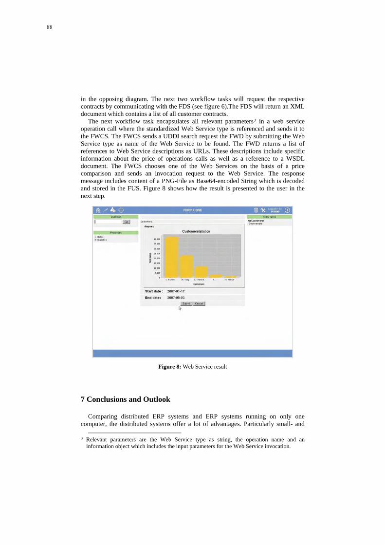
in the opposing diagram. The next two workflow tasks will request the respective contracts by communicating with the FDS (see figure 6).The FDS will return an XML document which contains a list of all customer contracts.
The next workflow task encapsulates all relevant parameters3 in a web service operation call where the standardized Web Service type is referenced and sends it to the FWCS. The FWCS sends a UDDI search request the FWD by submitting the Web Service type as name of the Web Service to be found. The FWD returns a list of references to Web Service descriptions as URLs. These descriptions include specific information about the price of operations calls as well as a reference to a WSDL document. The FWCS chooses one of the Web Services on the basis of a price comparison and sends an invocation request to the Web Service. The response message includes content of a PNG-File as Base64-encoded String which is decoded and stored in the FUS. Figure 8 shows how the result is presented to the user in the next step.
Figure 8: Web Service result
7 Conclusions and Outlook
Comparing distributed ERP systems and ERP systems running on only one computer, the distributed systems offer a lot of advantages. Particularly small- and
3 Relevant parameters are the Web Service type as string, the operation name and an
information object which includes the input parameters for the Web Service invocation.
88

medium sized Enterprises (SMB) benefit from using shared resources. The example in paragraph 6 shows how the system is able to react on market changes by comparing the prices of Web Service operation calls. However, the design of distributed system architectures is subject to a number of problems [2, 3]. The paper addresses the problem of redundant data in business application systems of independent vendors presents a basis for the standardization of ERP system components that are provided as Web Services. A standardized data model builds the basis for message and service standardization. The hierarchical structure of the presented standard advances the reuse of existing data types. Furthermore we presented a reference architecture of FERP systems which reduces the necessity of data transformation functions in business process descriptions. The standardization of the syntactic level is only the first step. Semantic, Behaviour, synchronization and quality of Web Services must flow into the definition of an overall ERP system standard. The future work must pick up these problems to realize the vision of a loosely coupled ERP system which allows the dynamic outsourcing of applications [5, 7] and the combination of software components of different providers.
References
1. Brehm, N., Marx Gómez, J.: Web Service-based specification and implementation of functional components in Federated ERP-Systems. In: Abramowicz, W. (ed.): 10th International Conference on Business Information Systems. Springer, Poznan, Poland (2007) 133-146
2. Brehm, N., Marx Gómez, J.: Secure Web Service-based resource sharing in ERP networks. International Journal on Information Privacy and Security (JIPS) 1 (2005) 29-48
3. Brehm, N., Marx Gómez, J.: Standardization approach for Federated ERP systems based on Web Services. 1st International Workshop on Engineering Service Compositions, Amsterdam (2005)
4. Brehm, N., Marx Gómez, J.: Federated ERP-Systems on the basis of Web Services and P2P networks. International Journal of Information Technology and Management (IJITM) (2007)
5. Brehm, N., Marx Gómez, J., Rautenstrauch, C.: An ERP solution based on web services and peer-to-peer networks for small and medium enterprises. International Journal of Information Systems and Change Management (IJISCM) 1 (2005) 99-111
6. Cuomo, G.: IBM SOA “on the Edge”. ACM SIGMOD international conference on Management of data. ACM Press, Baltimore, Maryland (2005) 840-843
7. Dan, A., Davis, D., Kearney, R., Keller, A., King, R., Kuebler, D., Ludwig, H., Polan, M., Speitzer, M., Youssef, A.: Web services on demand: WSLA-driven automated management. IBM SYSTEMS JOURNAL 43 (2004) 136-158
8. Vogt, C.: Intractable ERP: a comprehensive analysis of failed enterprise-resource-planning projects. Software Engineering Notes 27 (2002) 62-68
89

Resource Metrics for Service-OrientedInfrastructures
Dmytro Rud1, Andreas Schmietendorf1,2, and Reiner Dumke1
1 Software Engineering Group, Department of Distributed Systems,Faculty of Computer Science, Otto von Guericke University of Magdeburg,
Universitatsplatz 2, 39106 Magdeburg, Germany{rud, schmiete, dumke}@ivs.cs.uni-magdeburg.de
2 Berlin School of Economics, Faculty of Company-Linked Programmes,Neue Bahnhofstr. 11-17, 10245 Berlin, Germany
Abstract. Resource quality is one of the dimensions of software qualityassessment and must be appropriately addressed in service-oriented ar-chitecture. In this paper some resource metrics for distributed systemsthat conform to the service-oriented concepts will be proposed. Simi-larities and differences between service-oriented, component-based andweb-based software engineering approaches will be analysed in the con-text of involved resources and their quality impact.
1 Introduction
Software quality assessment is an important objective of software engineeringand has big relevance in the context of SOA as well. The three dimensionsof software quality are product, process and resources. In this paper we willpresent our view on significant run-time resource properties in service-orientedinfrastructures.
Note that service-oriented architecture is an approach/an ideology, not aproduct. Therefore it is impossible to attribute neither resources nor resourcemetrics to it. Instead of that, the metrics introduced in this paper relate to dis-tributed software systems built in accordance with SOA – i.e. implementationsof the SOA principle. These distributed systems will be hereinafter referred toas “service-oriented infrastructures” or “service-oriented systems” (simply “sys-tems” for short).
We will consider the following resources in service-oriented systems:
Network infrastructure. Its concrete logical topology can be point-to-point,bus (e.g. when a Enterprise Service Bus is used as an intermediate accesslayer), or some combination of them.
Service provider nodes. Each node is connected to the network and hosts asoftware infrastructure (application server(s)) that runs the services (serviceinstances) and provides access to service endpoints and service metadata.
90

Services – pieces of software running on the nodes, whose functionalities andmetadata are uniformly accessible for clients through the network.
Service functionalities (reactions to classes of incoming messages).Under RPC3-oriented interaction style this corresponds to operations’ in-vocations, but the dominant interaction style today is document-oriented(i.e. asynchronous messaging), therefore the term “functionality” seems tobe more correct here. Note also that some service design approaches con-sider every service to possess only one functionality (i.e. to provide a singleoperation when adhering to the RPC-oriented style). In this case the terms“service” and “service functionality” are synonymous.
There are also a few generalized metrics which relate to the system as a whole.Due to dynamic nature of service-oriented systems, the boundary between
product and resource, i.e. between design-time (static) and run-time (dynamic)properties, is somewhat diffused. For example, message sizes can be consideredas either product or resource metrics.
Metrics proposed in this paper are intended to help answer the followingquestions:
– What is the current utilization of network and nodes?– How much is it influenced by an invocation of a service’s functionality?– Are service versions managed well?– What is the performance behavior of elementary and composite services?
The rest of the paper is organized as follows. The next section gives a reviewof related work. Section 3 discusses the question of the applicability of resourcemetrics from other distributed software architectures in the context of SOA. Ourmetrics are introduced in Section 4. Section 5 concludes the paper.
2 Related Work
Quality assessment and assurance of service-oriented infrastructures constitutean actual research topic. The product quality aspect, in particular service designguidelines, is well discussed in [1, 2]. We had presented a set of product metricsin [3]. As mentioned in the introduction, some product metrics can be relevantin the resource context as well, therefore some metrics from [3] will appear inthis paper too. A formal quality model of single web services is described in [4],web services availability and performance problems are examined in [5].
Although there exist many tools on the market that monitor and analyseresource utilization in service-oriented systems, this subject is practically not inthe least reflected in scientific literature. One of likely causes for this situation isthe fact that there are many ways to implement SOA, and it is thus complicatedto develop a resource quality model that would fit for all of them.
Explanation of resources’ impact on performance and availability of web ap-plications and client-server systems is given in [6]. Caching and XML processing3 Remote procedure call
91

issues are discussed in [7]. Author of [8] asserts that the rate of valid transactioncompletion should be considered as the key run-time performance metric forSOA environments.
Resource metrics are actually used by service management frameworks whichprovide functionalities like service performance monitoring or service matchmak-ing. These frameworks include, for example, WSLA [9], WSOI [10], WSMN [11],WS-QoS [12], and many other industrial and academical research projects [5].
3 SOA’s Resemblances to Component- and Web-BasedApplications
From the resource consumption point of view, service-oriented infrastructuresshare some properties with component-based [13, 14] and web-based [6] applica-tions. Therefore arises the question of whether and to what extent is it possible toapply existing resource metrics from the component-based software engineering(CBSE) and web applications domains in the context of SOA. This applicabilityseems to be substantial, but the following conceptual differences between therespective approaches must be taken into account:
– Services can be composite (i.e. represent structured collaborations of otherservices, possibly with many “cascading” levels), while component-based andweb-based applications do not support this technique as a rule.
– In CBSE it is impossible that many versions of a component are availablesimultaneously (in web engineering there is no version concept at all), butthis can be the case in a service-oriented system.
– Unlike components, services involved in a transaction (in a composite serviceinvocation, a business process, a workflow) can reside on different nodes inthe network (thus possibly in different responsibility domains) and do notshare single address space. Communication between services is thus unreli-able and relatively slow, and the data transferring time cannot be neglected.
– Services represent functionalities and are generally stateless by design (likeweb resources, but unlike components)4, therefore replication and load balan-cing can be arranged. Replication mechanisms give the possibility to recovera service collaboration in the case of partial failure.
– Unlike both component-based and web-based applications, service interac-tions can proceed asynchronously. Therefore performance metrics like re-sponse time are not always available.
– Non-functional run-time properties of services are often explicitly and for-mally (i.e. machine-readably) described in form of service or operational levelagreements (SLA or OLA, respectively). Service providers are responsible forSLA fulfillment. This approach is rather uncommon in component-based andweb-based environments.
– An especial resource in service-oriented systems is services’ metadata.4 Some types of services, e.g. web services, can use session management mechanisms,
but this approach is not widely adopted.
92

4 Introduction of the Metrics
In this section we describe our resource metrics for service-oriented infrastruc-tures. The following three resource quality aspects will be considered in thisconnection: performance, service versioning, and reliability. Each aspect will bediscussed in its own subsection.
4.1 Performance
The main performance characteristic of the network is its (current) throughput.It depends on the network topology. When a centralized bus like ESB is used,the throughput can be considered to be consistent in the whole system; in thiscase, the perfomance is determined for the most part not by throughputs be-tween connected components and the ESB, but by the ESB’s internal processingmechanisms like XSLT transformations, intermediate storage, security, transac-tion management, ans so on. However, if the ESB is used in an inter-enterpriseenvironment, network latencies for the communication links between the bus and(external) components can have to be considered as well.
In the latter case, as well as in the absence of a centralized middleware, i.e.when every link between a pair of nodes has its own throughput value, networkperformance metrics relate to point-to-point throughput.
For these two variants we correspondingly introduce the following metrics:
CTY – Consistent Throughput in the System,T2N [n1, n2] – Throughput between 2 Nodes n1 and n2.
Unit of measurement for them is bytes/sec.Performance of a node is first of all characterized by its (current) utilization,
defined as fraction of time during which the node is busy with serving incomingrequests. Other performance indicators are message rates and network trafficprocessed by the node. These properties are covered by the metrics:
UN [n] – Overall Utilization of the Node n,IMRN [n] – Incoming Message Rate of the Node n (messages/sec),OMRN [n] – Outgoing Message Rate of the Node n (messages/sec),ITN [n] – Incoming Traffic of the Node n (bytes/sec), andOTN [n] – Outgoing Traffic of the Node n (bytes/sec).
(The four latter metrics have been already introduced in [3].)As mentioned above, utilization of nodes constitutes from fractions of time
used to serve individual requests (to execute certain functionalities in responseto incoming messages). Average sizes of such fractions (“processing costs” ofaverage individual requests) can be considered as performance metrics on deepspecification level. In the network throughput context, every service functionality
93

is characterized by sizes of input and – in the case of RPC interaction style –output messages5. In order to be compatible with notational conventions usedin our product metrics proposal [3], we will use here the term “operation” in thesense of “service functionality”. Corresponding metrics are:
AUO[m] – Average Utilization (of the node that provides thecorresponding service) caused by the Operation m (seconds),
AIMSO[m] – Average Input Message Size for the Operation m (bytes),AOMSO[m] – Average Output Message Size for the Operation m (bytes).
If the service under consideration is composite, invocation of its functionali-ties imply a number of cascading calls to subordinate services. These calls causeadditional utilization of corresponding nodes. To have an exact picture of theinfluence of an invocation upon utilizations of all N nodes of the system, thetuple
〈AUO1[m], AUO2[m], . . . , AUON [m]〉
should be analysed instead of the consideration of the single node. However it isobvious that the white-box view is necessary to obtain these value.
One of possible scenarios of SOA implementation is a system consisting of aset of service providers, a business process integrator and a set of clients of thelatter, i.e. business process consumers. The mission of the integrator is to selectan optimal set of third-party services, to orchestrate a composite service fromthem by filling out a business process description template with all informationnecessary to start the process – i.e. with partner links, addresses, etc., and finallyto provide the latter to the customers.
The current and maximal possible numbers of simultaneously running busi-ness processes (“top-level transactions”) can be important generalized indicatorsfor the integrator. Therefore we introduce two corresponding metrics:
ANBPY – Average Number of Business Processes in the System,BPCY – Business Processes’ Capacity of the System.
To calculate the business processes’ capacity of the system, deep analysis ofthe processes and their environment is necessary. An initial approach for suchanalysis was proposed in [15].
Other generalized metrics (already mentioned in [3]) give a “bird’s-eye view”on the system’s performance:
MRY – Overall Message Rate in the System (messages/sec),NTY – Overall Network Traffic in the System per one unit of time
(bytes/sec).
5 Fault messages should be taken into account as well
94

Note that we do not take into account possible use of caching mechanisms.Firstly, it is complicated to determine caching impact on resources utilizationin technology-independent manner. Secondly, it is not very clear at all what thecaching can mean under asynchronous document-oriented interaction style (asopposed to synchronous RPC-oriented style). For roughly the same reason wedo not discuss scalability issues here.
4.2 Service Versioning
The possibility of different versions of the same service to be active simultane-ously is a distinguishing feature of service-oriented systems. Version managementhas its quality aspects and thus must be addressed by software engineering inorder to avoid negative consequences of poor versioning organization. In particu-lar, a service with many short-lived versions can complicate both its maintenanceand development of clients.
Two types of resources are appropriate in this context – there are installedservice versions per se and services’ metadata, i.e. formal (machine-readable)descriptions of services’ functional and non-functional properties. A metadatarepository (or registry) is an essential component of service-oriented infrastruc-tures, serving for loose coupling and dynamic binding, and enabling agility inthat way.
For individual services, the following versioning metrics may be relevant:
CV S[s] – Count of (simultaneously deployed) Versions of the Service s,ALTV S[s] – Average Life Time of Versions of the Service s.
Their counterparts on the system level are:
ACSV Y – Average Count of Services’ Versions in the System,ALTSV Y – Average Life Time of Services’ Versions in the System.
In the absence of any versioning mechanisms, the only possible metric is
MCFS[s] – Metadata Change Frequency of the Service s.
Service’s metadata instability can break the work of existing clients andshould be avoided. Proper versioning mechanisms should be used instead.
One of possible services’ metadata types are service level agreements (SLAs),which have been already mentioned in this paper. The next subsection discussesSLA fulfillment issues and introduces a few SLA-related metrics.
4.3 Reliability
Service-level agreements are parts of service contracts and uniformly describenon-functional properties of the services. Sustained fulfillment of the SLA guar-antees can be considered as the main quality criterion of a service.
Three conventional SLA fulfillment states can be distinguished:
95

Green area – All SLA conditions are consistently met,Yellow area – Although SLA conditions are met, indicators (for example, some
aggregated performance indices) come near to the prescribed threshold,Red area – SOA conditions are not met.
On the basis of these areas we define the following metrics:
– SLACS[s] – SLA Compliance of the Service s, measured as the fraction oftime during which all SLA fulfillment indicators of the service lie in greenand/or yellow areas,
– SLAV DS[s] – SLA Violation Danger of the Service s, measured as
fraction of time in yellow areafraction of time in green and yellow areas
.
Faults (improper or missing reactions to incoming messages) are one of themost probable causes of SLA violations. Possible fault manifestations are:
– The service is unable to receive the incoming message,– The service responds with a fault message,– The service sends no response at all (for RPC-styled interaction),– The non-fault response comes too late.
Alternatively to the SLA-related metrics described above, the following met-rics can be used to describe faults which happen in the system, i.e. to address anarrower and more technical view on SLA fulfillment (and to avoid subjectivitycaused by the choice of SLA fulfillment states’ boundaries):
FRO[m] – Fault Rate of the Operation m per one unit of time. This value
can be calculated ascount of faults
count of received messages, and
FRY – Overall Fault Rate in the System.
Turning back to the business process integrator scenario (see Subsection 4.1),we can draw a parallel between these fault metrics and the rate of valid top-leveltransactions (composite business processes) completion metric proposed is [8].Fault rates of the composed services can be considered as most important qualityindicators of the business process integrator’s work.
5 Conclusions
In this paper we have presented some resource metrics for service-oriented in-frastructures. From the viewpoint of resource utilization, there are not so muchdifferences between service-oriented, component-based and web-based applica-tions, but their nevertheless exist, and we have tried to take them into accountin our analysis.
96

Resource Performance Versioning Reliabilitymetrics metrics metrics
Network CTY, T2N,MRY, NTY
Service provider nodes UN, ITN, OTN,IMRN, OMRN
Services CVS, ALTVS, SLACS,MCFS SLAVDS
Service functionalities AUO, AIMSO, FRO(operations) AOMSO
System as a whole ANBPY, BPCY ACSVY, ALTSVY FRYTable 1. Classification of introduced metrics
Table 1 systematizes the proposed metrics and shows the correspondencebetween various quality aspects covered by the metrics and corresponding re-sources.
The proposed set of metrics is definitely not exhaustive, but it constitutes abasis for discussion and for subsequent work in this field.
The metrics are formulated in a technology-independent manner, specifictechnologies and measurement procedures are out of scope of the paper. There-upon certain adjustment can become neccessary to make the metrics applicablein the context of concrete systems.
One of evident possible improvements of our resource quality model can lie inthe consideration of the temporal aspect. For example, message rates and faultrates can be time-dependent. This peculiarity can be very important if we haveto develop system performance models like the one in [15]. But standard mea-surement scales (nominal, ordinal, interval, ratio, and absolute) do not permit touse functions (e.g. statistical distributions) as metrics’ values. The same appliesto tuple-structured data as occurred in Subsection 4.1.
References
1. Artus, D.J.N.: SOA realization: Service design princi-ples. IBM developerWorks (February 2006) http://www-128.ibm.com/developerworks/webservices/library/ws-soa-design/.
2. Hess, A., Humm, B., Voß, M.: Regeln fur serviceorientierte Architekturen hoherQualitat. Informatik Spektrum 29/6 (Dezember 2006) 395–411 (“Rules for service-oriented architectures of high quality”, in German).
3. Rud, D., Schmietendorf, A., Dumke, R.: Product metrics for service-orientedinfrastructures. In Abran, A., Bundschuh, M., Buren, G., Dumke, R., eds.:Applied Software Measurement. Proc. of the International Workshop on Soft-ware Metrics and DASMA Software Metrik Kongress (IWSM/MetriKon 2006).Magdeburger Schriften zum Empirischen Software Engineering, Potsdam, Ger-many, Hasso-Plattner-Institut, Shaker Verlag (November 2006) 161–174
4. Thielen, M.: Qualitatssicherung von Webservices. Entwurf eines allgemeinenQualitatsmodells fur eine Webservice-Zugriffsschicht. Master’s thesis, Universitat
97

Koblenz-Landau (2004) (“Quality assurance of web services. Development of ageneric quality model for a web service access layer”, in German).
5. Rud, D.: Qualitat von Web Services: Messung und Sicherung der Performance.VDM Verlag Dr. Muller, Saarbrucken (2006) (“Quality of web services: Measure-ment and assurance of performance”, in German).
6. Menasce, D.A., Almeida, V.A.F.: Capacity planning for web services: metrics,models, and methods. Prentice Hall (2002)
7. Cohen, F.: FastSOA: The way to use native XML technology to achieve serviceoriented architecture governance, scalability, and performance. Morgan KaufmannSeries in Data Management Systems. Elsevier Books, Oxford (January 2007)
8. Noel, J.: Transaction completion: The new performance metric for ser-vice oriented architecture environments. Technical report, Ptak, Noel& Associates (2005) http://www.ptaknoelassociates.com/content/library/2005/Certagon transaction completion.pdf.
9. Dan, A., Davis, D., Kearney, R., Keller, A., King, R., Kuebler, D., Ludwig,H., Polan, M., Spreitzer, M., Youssef, A.: Web services on demand: WSLA-driven automated management. IBM Systems Journal 43(1) (2004) 136–158http://www.research.ibm.com/journal/sj/431/dan.pdf.
10. Tosic, V.: Service Offerings for XML Web Services and Their Man-agement Applications. PhD thesis, Department of Systems and Com-puter Engineering, Carleton University, Ottawa, Canada (August 2004)http://flash.lakeheadu.ca/∼vtosic/TosicThesis-Final.pdf.
11. Machiraju, V., Sahai, A., van Moorsel, A.: Web services management network:An overlay network for federated service management. Technical Report HPL-2002-234, HP Labs (2002) http://www.hpl.hp.com/techreports/2002/HPL-2002-234.pdf.
12. Tian, M.: QoS integration in Web services with the WS-QoS framework. PhDthesis, Fachbereich Mathematik u. Informatik, Freie Universitat Berlin (November2005) http://www.diss.fu-berlin.de/2005/326/index.html.
13. Gao, J.Z., Tsao, H.S.J., Wu, Y.: Testing and quality assurance for component-based software. Artech House (2003)
14. Szyperski, C.: Component software: Beyond object-oriented programming. Addi-son Wesley (1998)
15. Rud, D., Schmietendorf, A., Dumke, R.: Performance modeling of WS-BPEL-basedweb service compositions. In: Proc. of the IEEE Service Computing Workshops(SCC 2006), Los Alamitos, CA, USA (September 2006) 140–147
98

Model Driven Testing of SOA–based Software
Chris Lenz, Joanna Chimiak–Opoka, Ruth Breu
Quality Engineering Research GroupInstitute of Computer Science, University of Innsbruck
Technikerstrasse 21a, A–6020 [email protected]
Abstract. Specification and implementation of tests for complex, multi–user systems, like those based on SOA, is a demanding and time–con-suming task. To reduce time and effort the specification of tests can bedone at the model level. We propose platform independent test specifi-cation with our extension of the UML Testing Profile. The three phasesof our approach: test design, generation and execution, are explainedon an exemplary simple application. We show the differences and simi-larities of a desktop and a web services variant of the application incontext of all phases. At the model level the approach abstracts fromplatform specific information, nevertheless this information is providedat the test infrastructure level of a proposed architecture. Based on theexample application we point out extension possibilities of general char-acter (templates, data pools) and specific for web services (integrationwith WSDL, BPEL).
1 Introduction
Testing is an important and demanding task, and the continuously increasingsize and complexity of software systems make the testing task more complexand increase the size of test code [1,2]. In the field of software developmentthe complexity of systems has been reduced by using abstract specifications.Models are used to represent the more complex entities to understand, com-municate, explore alternatives, simulate, emulate, calibrate, evaluate and vali-date software [3]. Therefore it is a logical consequence to represent test code asmodels, too. In the case of test models all advantages mentioned before are pro-vided. The benefit of models lies in their abstractness as opposed to implementa-tion specific concreteness of code [4]. Because of used technologies or platformscode needs to contain implementation specific information. By defining domainspecific languages (e.g. UML Profiles) and corresponding interpretations, it ispossible to represent code in a very compact way. These are the main principlesof Model Driven Architecture (MDA) [5,6] and Model Driven Software Deve-lopment (MDSD) [4], where the models represent exactly the generated code.The models are compact and expressive. The compactness and expressivenessare achieved by using of a domain specific language (DSL), the semantics ofthe DSL is specified by a definition of the underlying transformation, which
99

2
represent the conversion from model to code. The models provide an easier tounderstand overview for a human user, but the complete information needed bytools is captured in the transformation and the code. MDA and MDSD aim atgenerating code out of models, whereby the big benefit of such approaches isthe late technology binding. For example the decision of using Plain Old JAVAObjects (POJO1) or J2EE2 must not be done in early development stages, achange of technology can be done more easily in model driven approaches thanin code driven approaches. That is because in model driven approaches only thetransformations have to be changed, and the code can be regenerated.
Model driven test development offers the same benefits. In the specificationof tests there are only marginal differences between testing methods for differenttarget platforms, e.g. POJO classes and web services (WS). In both cases onlythe access to the tested methods is different, we have local method calls forPOJO and for WS remote calls.
In the context of this paper we use a definition of Service Oriented Archi-tecture (SOA) given in [7]. SOA is defined as an architecture which is based onservices (components). Each component can be seen as a logical unit of workthat fulfils five properties:
1. It can be used in multiple projects,
2. It is designed independently of any specific project and system context,
3. It can be composed with other components,
4. It is encapsulated, i.e. only the interfaces are visible and the implementationcannot be modified,
5. It can be deployed and installed as an independent atomic unit and laterupgraded independently of the remainder of the system.
For the testing purpose the points 2, 4 and 5 are the most relevant ones.Independence is important for testing without other components, the encapsu-lation and definition of interfaces is useful for the identification of test cases. Thepossibility to install components independently allows to set up test systems forthe component under test.
Model driven test development does not oblige which software developmentmethodology has to be used. It suits to testing first methodologies like Agile [8]and Lean [9] development as well as for MDSD.
The rest of the paper is organized as follows. In section 2 we introduce ourframework for model driven testing and present its architecture. The testingapproach is divided into three phases: design, code generation and execution,which are briefly explained in section 2 and presented on the running examplein section 3. In section 4 we explain further extensions and point out possiblefuture research topics. Section 5 presents concluding remarks.
1 http://www.martinfowler.com/bliki/POJO.html2 http://java.sun.com/javaee/
100
3
2 The Telling Test Stories Framework
Telling Test Stories has the goal to bring requirement specifications closer to thetest specifications. The requirements specify how software should work, whichactors are involved and business classes are used. Tests are used to assure thatthe software reacts in the specified manner.
Software testing can be performed at different levels along the developmentprocess. The three major levels can be distinguished: unit, integration and systemtests [10]. Unit testing verifies the functioning of isolated software pieces, whichare separately testable. Integration testing verifies the interaction between soft-ware components. System testing is concerned with the behavior of a wholesystem. Although Telling Test Stories approach can be used for all types of testsmentioned above, it is dedicated for integration and system testing.
Figure 1 illustrates the architecture of Telling Test Stories. The componentsdepicted in the figure can be assigned to the three phases of the process, namelydesign, generation and execution. The test specification and the transformationmodel are both created at design time. Then the test code generation out ofthe test specification is supported by the Open Architecture Ware framework(OAW3) and the transformation templates (transformation model in Figure 1).The output of the generation phase is test code. These three artefacts are allplatform independent, that means it does not matter which technologies are usedto develop the system.
The remaining components are related to the execution phase. A test engineis required for the test execution, in the following use cases the JUnit [11] frame-work was used. The execution engine is used to test a given system, also calledSystem Under Test (SUT). In general it is not possible to test the SUT in auniversal manner, and therefore some glue code is needed between test code andSUT. In other test approaches like Fitnesse [12,13] this glue code is called fixture.The fixture code encapsulates code which is needed to simplify the test code.The transformation also provides platform specific resources as output, they arefor example used to configure the fixture, provide mock and stub4 classes.
Design Phase In this phase the requirement specification as well as the tests aredesigned and the code generation templates are developed. The test specificationis developed as UML diagrams, to specify the SUT, TestContexts or TestCases ourapproach is strongly oriented on the OMG5 UML Testing Profile (U2TP) [14].We extended the syntax of U2TP by an additional stereotype for Message called�Assert� (c.f. Figure 2). Despite this extension we remain conform to the U2TPproposal.
In MDA we distinguish between platform independent (PIM) and platformspecific model (PSM). In our approach the requirement specification and alsothe test models can be seen as PIM, the code transformation templates represent
3 http://www.eclipse.org/gmt/oaw/4 http://www.martinfowler.com/articles/mocksArentStubs.html5 Object Management Group http://www.omg.org/
101
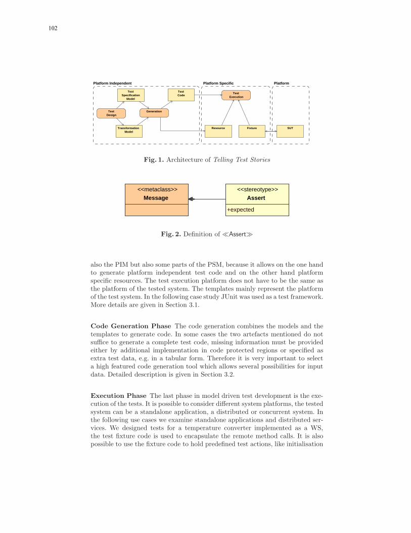
4
GenerationTestDesign
TestExecution
TransformationModel
FixtureResource
TestCode
SUT
TestSpecification
Model
PlatformPlatform SpecificPlatform Independent
Fig. 1. Architecture of Telling Test Stories
<<stereotype>>
Assert
+expected
<<metaclass>>
Message
Fig. 2. Definition of �Assert�
also the PIM but also some parts of the PSM, because it allows on the one handto generate platform independent test code and on the other hand platformspecific resources. The test execution platform does not have to be the same asthe platform of the tested system. The templates mainly represent the platformof the test system. In the following case study JUnit was used as a test framework.More details are given in Section 3.1.
Code Generation Phase The code generation combines the models and thetemplates to generate code. In some cases the two artefacts mentioned do notsuffice to generate a complete test code, missing information must be providedeither by additional implementation in code protected regions or specified asextra test data, e.g. in a tabular form. Therefore it is very important to selecta high featured code generation tool which allows several possibilities for inputdata. Detailed description is given in Section 3.2.
Execution Phase The last phase in model driven test development is the exe-cution of the tests. It is possible to consider different system platforms, the testedsystem can be a standalone application, a distributed or concurrent system. Inthe following use cases we examine standalone applications and distributed ser-vices. We designed tests for a temperature converter implemented as a WS,the test fixture code is used to encapsulate the remote method calls. It is alsopossible to use the fixture code to hold predefined test actions, like initialisation
102

5
code for databases, or to hold more complex test states which can be evaluatedin the test code. Fixtures are very helpful in earlier test stages, if the SUT is notfully implemented and preliminary tests are made, it is possible to implementfeatures very rudimentary in the fixture code. For example, if we test a sequenceof web service calls, and one of these web services is not implemented yet, wecan implement a rudimentary functionality of this web service in the fixture.Therefore it is possible to test complex processes even if implementation is notcomplete. Details are given in Section 3.3.
3 The converter example
In this section the application of the Telling Test Stories approach is demon-strated on an exemplary application. In the following subsections the threephases of the approach are described using an example.
3.1 Test Design Phase
The Telling Test Stories approach starts with the definition of the System UnderTest (SUT). In the simplest case this could be one class with a few methods.
<<SUT>>
Converter
+celsiusToFarenheit( celsius : float )+farenheitToCelsius( farenheit : float )
Fig. 3. System Under Test
Figure 3 illustrates the definition of a temperature Converter class. It is notspecified if this is implemented as plain JAVA client application or as web service.For the definition of a test suite for the temperature converter this is negligible.This information is needed first when the code for the test suite is implementedor generated.
In Figure 4 the definition of a test suite in UML is illustrated. Part (a) shows aclass which is annotated with the stereotype �TestContext�. This indicates thatthe class ConverterTest is a test suite which can contain zero to many TestCases,test cases are defined by methods annotated by the stereotype �TestCase�.Each test case can have a deposited behavioural diagram like a sequence oractivity diagram. Parts (b) and (c) of Figure 4 show the two sequence diagramsof the farenheitToCelsius and the celsiusToFarenheit test cases, respectively. Thetest cases are described as follows.
103

6
farenheitToCelsius The test method calls the temperature Converter method:farenheitToCelsius(celsius:float):float. This implies that an instance of the Con-verter class was created. The converter is called with the farenheit value 41f
and the test expects a return value of 5f ((b) in Figure 4).celsiusToFarenheit This test works near the same like the farenheitToCelsius
one. The celsiusToFarenheit method of the Converter is called with 5f andthe expected return value is 41f ((c) in Figure 4).
<<TestContext>>
ConverterTest
<<TestCase>>+testCelsiusToFarenheit()<<TestCase>>+testFarenheitToCelsius()
(a)
<<TestContext>>
: ConverterTest<<SUT>>
: Converter
celsiusToFarenheit(celsius="5f")1:
<<Assert>>{expected = 41f}
(b)
<<TestContext>>
: ConverterTest<<SUT>>
: Converter
farenheitToCelsius(farenheit="41f")1:
<<Assert>>{expected = 5f}
(c)
Fig. 4. Test Specification
It is significant that at test design time it is not relevant what the targetlanguage and platform of the implementation of temperature converter is. Itcould either be implemented in C# or JAVA and as desktop application or webservice.
3.2 Test Code Generation Phase
As mentioned before, it does not matter in which technology the Converter isimplemented. We have implemented two variants of the system a plain JAVAclient application and a web service. The conversion from model to code hasto consider implementation details. For the conversion we use the MDSD toolOpen Architecture Ware. The tool is able to interpret the models, and generatecode out of them. The transformation is a template based approach.
1 public class ConverterTest {
2 @Test
104

7
3 public void testCelsiusToFarenheit()
4 throws RemoteException {
5 // Definition Block
6 ConverterFixture c = new ConverterFixture ();
7 // Message Block
8 assertEquals (41f, c.celsiusToFarenheit (5f));
9 }
10
11 @Test
12 public void testFarenheitToCelsius()
13 throws RemoteException {
14 // Definition Block
15 ConverterFixture c = new ConverterFixture ();
16 // Message Block
17 assertEquals (5f, c.farenheitToCelsius (41f));
18 }
19 }
Listing 1.1. Generated test suite for the plain java and webserviceimplementation.
As show in Figure 1, out of the test specification model a platform indepen-dent test code is generated. For our example this is listed in Listing 1.1. Thisimplementation is straightforward, and uses the JUnit testing framework as testengine. The test suite implements for each test case a new method, which is an-notated with @Test. Each test case consists of two blocks, the definition block,and the message block.
The definition block defines for each class used in the sequence diagram anew object. An object can be instantiated with its default constructor orone defined explicitly in the sequence diagram by a message annotated withstereotype �Constructor�.
The message block represents a method call for each message in the sequencediagram. If the message is annotated with the stereotype �Assert�, theresult of the method call is checked against an expected result.
Platform independent in this case means independent on the technology usedin the SUT, clearly it has the restrictions of the used test execution engine. Inour case the test execution engine is JUnit, which implies that the tests have tobe written in JAVA. The code in Listing 1.1 can now be used to test the plainjava application or the web service. The test does not reference the SUT it self,it works on the SUT fixture, which fills the gap between the test code and theSUT.
Plain Java The plain java test is a very simplified test, the ConverterFixture
in this case is an Adapter, which routes the methods calls of the fixture to themethods of the Converter instance (e.g. Listing 1.2).
105

8
1 public class ConverterFixture {
2 private Converter converter = null ;
3
4 public ConverterFixture () {
5 _initConverterFixture ();
6 }
7
8 private void _initConverterFixture () {
9 converter = new Converter ();
10 }
11
12 public float celsiusToFarenheit (float celsius ) {
13 if ( converter == null )
14 _initConverterProxy ();
15 return converter . celsiusToFarenheit (celsius);
16 }
17
18 public float farenheitToCelsius (float farenheit ) {
19 if ( converter == null )
20 _initConverterProxy ();
21 return converter . farenheitToCelsius (farenheit
);
22 }
23 }
Listing 1.2. Test fixture for the plain java implementation.
If the fixtures are simple and follow a well known principle like in this case(create for each SUT class a fixture class, provide all constructors of the originalclass and instantiate an original class in it, provide all original methods an routethe method calls to the original class), it is also possible to generate the fixturesout of the test specification. This is shown in Figure 1 by generating resources.
Web Services Listing 1.3 illustrates a code snippet of the test fixture used forthe web service implementation. The only difference in this Listing to the Listing1.2 is the changed initConverterProxy method.
The ConverterFixture is the entry point for a couple of classes which encap-sulate the remote method calls to the converter web service. These fixture or alsocalled proxy classes are generated by the Eclipse Web Tools Platform project6.
Also this fixture classes can be generated in the generation phase.
1 ...
2 private void _initConverterProxy () {
3 try {
4 converter = (new wtp. ConverterServiceLocator()).
getConverter ();
5 if (converter != null ) {
6 WTP http://www.eclipse.org/webtools/
106
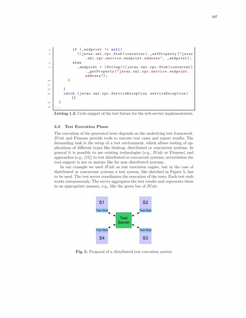
9
6 if (_endpoint != null )
7 (( javax.xml.rpc.Stub )converter )._setProperty ("javax
.xml.rpc.service .endpoint .address", _endpoint );
8 else
9 _endpoint = (String)(( javax.xml.rpc.Stub )converter )
._getProperty ("javax.xml.rpc.service. endpoint .
address");
10 }
11
12 }
13 catch (javax.xml.rpc.ServiceException serviceException )
{}
14 }
15 ...
Listing 1.3. Code snippet of the test fixture for the web service implementation.
3.3 Test Execution Phase
The execution of the generated tests depends on the underlying test framework.JUnit and Fitnesse provide tools to execute test cases and report results. Thedemanding task is the setup of a test environment, which allows testing of ap-plications of different types like desktop, distributed or concurrent systems. Ingeneral it is possible to use existing technologies (e.g., JUnit or Fitnesse) andapproaches (e.g., [15]) to test distributed or concurrent systems, nevertheless thetool support is not so mature like for non–distributed systems.
In our example we used JUnit as test execution engine, but in the case ofdistributed or concurrent systems a test system, like sketched in Figure 5, hasto be used. The test server coordinates the execution of the tests. Each test stubworks autonomously. The server aggregates the test results and represents themin an appropriate manner, e.g., like the green bar of JUnit.
Fig. 5. Proposal of a distributed test execution system
107

10
4 Further Extensions
The use case of the previous section illustrates in simplified manner the idea ofour approach. In this section we provide a few extensions of general character(Sections 4.1 and 4.2) and specific for web services (Section 4.3).
4.1 Templating
The aspect to be considered during test design is the possibility of diagramparametrisation and its interpretation for generation of different variants of testcases. It is not desirable to draw a new sequence diagram if only data changes.
The sequence diagrams could be seen as test templates. Thus the argumentsin the message calls have not to be concrete values or objects, they also canrepresent variables (c.f. Figure 6). To instantiate the given variables with realvalues, each diagram can be combined with a table. The columns represent thevariables, each row defines one instance of a the test case. In the example depictedin Figure 6 the generator would create 3 tests out of the sequence diagram andthe table.
<<TestContext>>
: ConverterTest<<SUT>>
: Converter $farenheit$ $celsius$
32 0
68 20
89.6 32
farenheitToCelsius(farenheit="$farenheit$")1:
<<Assert>>{expected = $celsius$ }
Fig. 6. Test template sequence diagram with data set
4.2 Data Pools
In the running example (Sections 3.1 and 4.1) all data used in diagrams wereof primitive types. This simplification was made for demonstration purposes, ingeneral more complex data types have to be considered. There are two kinds ofsituation when more complex data is required. The first is configuration of thesystem under test and the second is parametrisation of tests.
If we considered acceptance tests the system under test has to be initiatedand for some test cases there is a need to have the system in a particular statewith a corresponding set of data initialised. For this purpose it is useful to have
108

11
a pool of ready to use data and a pool of some standard actions, like databaseinitiation.
The data pool concept is also useful for the diagram templates parametri-sation. The parametrisation can be defined as before in the tabular form butinstead of values, the references to the objects from data pools can be used. Thefurther generalisation would be usage of exchangeable data pools for differenttests scenarios.
4.3 Domain Specific Input WSDL
Model driven test development seems to be a kind of domain driven testing,therefore the format of the requirement specification could vary depending onthe domain.
Web services by definition are a logical unit of work, which have defined inter-faces. These interfaces describe the requirements of the service, testing a serviceagainst his interface would be a logical consequence of this. Domain driven test-ing has the focus on testing by using domain specific test specifications.
The specification of test could be based on the definition of a web service,the web service definition language (WSDL) file. This file specifies all operationswhich are available by a service. It is possible to use the WSDL file and allow thetester to create sequence diagrams against it. Another possibility is to generate aUML class stereotyped with �SUT� out of the WSDL file. For each operationprovided by the service a method will be defined in the �SUT�.
5 Conclusion
The growing complexity of software applications needs solutions which allowcomplexity reduction by raising the abstraction level. The common examplesof such solutions are 4 GL programming languages, development and modelingframeworks. Model driven test development is a step further to achieve moremanageable and transparent software development. Model driven test develop-ment can be adapted to do integration testing, system testing and performancetesting.
The described Telling Test Stories approach relates software and tests at avery early phase. The test design is based on the requirement specification andin consequence tests are at a quite high abstraction level. After design phaseour approach supports test code generation and execution, as described in gen-eral in section 2 and on the temperature converter example in section 3. Thedifference between various platforms of the exemplary application appeared incode generation phase and in the fixture implementation. The proposed solutionis general and can be used for SOA applications, not necessarily based on webservices technology.
In section 4 we pointed out further extensions of test specification possibil-ities like templating, data pools and usage of other input specifications than
109

12
requirements specifications. For the web services application WSDL and BPELcan be used as the input specifications.
The focus of this paper was to present how model driven test developmentcan be applied to any target platform of the system under test, in particularfor web services. For the design of the platform independent tests we used theUML 2 Testing Platform (U2TP), which we extended with the Asset stereotype(section 2). To enable execution of the tests for a specific target platform ofthe system under test we used JUnit. But it is also possible to use use variousdifferent test execution engines (e.g. BPELUnit7, jfcUnit8, Fitnesse9, zibreve10).The generation of platform specific resources out of the test specification givesthe possibility for configuration or also implementation of fixtures.
References
1. Tsao, H., Wu, Y., Gao, J., Gao, J.: Testing and Quality Assurance for Component-Based Software. Artech House (2003)
2. Tian, J.: Software quality engineering: testing, quality assurance, and quantifiableimprovement. Wiley (2005)
3. Thomas, D.: Programming with Models - Modeling with Code. The Role of Mod-els in Software Development. in Journal of Object Technology vol .5, no. 8
(November -December 2006) pp. 15–194. Stahl, T., Volter, M.: Modellgetriebene Softwareentwicklung. dpunkt-Verl. (2005)5. Mukerji, J., Miller, J.: MDA Guide Version 1.0. 1 (2003)6. McNeile, A.: MDA: The Vision with the Hole? (2004)
http://www.metamaxim.com/download/documents/MDAv1.pdf.7. Aalst, W.v.d., Beisiegel, M., Hee, K.v., Konig, D., Stahl, C.: A SOA-Based Archi-
tecture Framework. In Leymann, F., Reisig, W., Thatte, S.R., Aalst, W.v.d., eds.:The Role of Business Processes in Service Oriented Architectures. Number 06291 inDagstuhl Seminar Proceedings, Internationales Begegnungs- und Forschungszen-trum fuer Informatik (IBFI), Schloss Dagstuhl, Germany (2006)
8. Beck, K.: Extreme Programming Das Manifest. Addison Weseley (2003)9. Poppendieck, M., Poppendieck, T.: Lean Software Developement. Number ISBN
0-321-15078-3 in The Agile Software Developement Series. Addison-Wesley (2003)10. Abran, A., Bourque, P., Dupuis, R., Moore, J.: Guide to the Software Engineering
Body of Knowledge–SWEBOK. IEEE Press Piscataway, NJ, USA (2001)11. Gamma, E., Beck, K.: JUnit (http://www.junit.org/index.htm) (2006)12. Martin, R.C., Martin, M.D.: Fitnesse (http://www.fitnesse.org) (2006)13. WardCunningham: Fit homepage (http://fit.c2.com) (2006)14. OMG: UML Testing Profile home page: http://www.fokus.gmd.de/u2tp/) (2006)15. Hartman, A., Kirshin, A., Nagin, K.: A test execution environment running ab-
stract tests for distributed software. Proceedings of Software Engineering andApplications, SEA 2002 (2002)
7 http://www.bpelunit.org/8 http://jfcunit.sourceforge.net/9 http://fitnesse.org/
10 http://www.zibreve.com/
110