proceedings of the ground-water/surface-water … of the ground-water/surface-water interactions...
TRANSCRIPT

Proceedings of the Ground-Water/Surface-Water Interactions Workshop July 2000
156
APPENDICES
Proceedings of the Ground-Water/Surface-Water Interactions Workshop July 2000
157
Appendix A: Workshop Participants List
Tom AaltoU.S. EPA, Region 8999 18th St.Mail Code: 8P2-HWDenver, CO 80202-2413Phone: (303) 312-6949Fax: (303) [email protected]
James BartolinoU.S. Geological Survey4501 Indian School Rd., Ste 200Albuquerque, NM 87110-3929Phone: (505) 262-5336Fax: (505) 262-5398 [email protected]
Katherine BaylorU.S. EPA, Region 9RCRA Corrective Action Office75 Hawthorne St.Mail Code: WST-5San Francisco, CA 94105Phone: (415) 744-2028Fax: (415) [email protected]
Ned BlackU.S. EPA, Region 975 Hawthorne St.Mail Code: SFD-8BSan Francisco, CA 94105Phone: (415) 744-2354Fax: (415) [email protected]
Randy BreedenU.S. EPA, Region 8999 18th St., Suite 500 Mail Code: 8P2-HWDenver, CO 80202-2466Phone: (303) 312-6522
Fax: (303) [email protected]
David BurrisAir Force Research Laboratory139 Barnes Dr.Mail Code: AFRL/MLQRTyndall AFB, FL 32403Phone: (850) 283-6035Fax: (850) [email protected]
Allen BurtonWright State UniversityInst. for Environmental Quality3640 Colonel Glenn Hwy. Dayton, OH 45435-0001Phone: (937) 775-2201Fax: (937) [email protected]
Judy CanovaSouth Carolina Dept. of Environ-mental Health and Conservation2600 Bull St. Columbia, SC 29201Phone: (803) 896-4046Fax: (803) [email protected]
Lisa CapronU.S. EPA , Region 577 W. Jackson Blvd.Mail Code: DE-9JChicago, IL 60604-3507Phone: (312) 886-0878Fax: (312) [email protected]
David ChartersU.S. EPA, EnvironmentalResponse Team
2890 Woodbridge Ave.Edison, NJ 08837-3679Phone: (732) 906-6825Fax: (732) [email protected]
Jungyill ChoiU.S. Geological Survey430 National Center12201 Sunrise Valley Dr. Mail Code: MS-431Reston, VA 20192Phone: (703) 648-5472Fax: (703) [email protected]
Brewster Conant Jr.University of WaterlooEarth Sciences DepartmentWaterloo, Ontario N2L 3G1Phone: (519) 888-4567, [email protected]
Martha ConklinUniversity of ArizonaDepartment of Hydrology andWater ResourcesP.O. Box 210011Tucson, AZ 85721-0011Phone: (520) 621-5829Fax: (520) [email protected]
D. Reide CorbettFlorida State UniversityDepartment of OceanographyP.O. Box 4320 Tallahassee, FL 32306-4320Phone: (850) 644-9914Fax: (850) [email protected]
Proceedings of the Ground-Water/Surface-Water Interactions Workshop July 2000
158
Cliff DahmUniversity of New MexicoDepartment of Biology Albuquerque, NM 87131Phone: (505) 277-2850Fax: (505) [email protected]
Kathy DaviesU.S. EPA, Region 31650 Arch St. Mail Code: 3HW41Philadelphia, PA 19103-2029Phone: (215) 814-3315Fax: (215) [email protected]
Joe DlugoszU.S. EPA, ORD/MED6201 Congdon Blvd.Duluth, MN 50408Phone: (218) 529-5215Fax: (218) [email protected]
Maureen DudleyDenver Department ofEnvironmental Health1391 Speer Blvd., Suite 700Denver, CO 80204Phone: (303) 285-4063Fax: (303) [email protected]
Bruce DuncanU.S. EPA, Region 101200 Sixth Ave.Mail Code: OEA-095Seattle, WA 98101Phone: (206) [email protected]
René FuentesU.S. EPA, Region 101200 Sixth Ave.Mail Code: OEA-095Seattle, WA 98101Phone: (206) 553-1599Fax: (206) [email protected]
Gayle GarmanNational Oceanic andAtmospheric Administration7600 Sand Point Way, NEMail Code: Bin C15700Seattle, WA 98115-0070Phone: (206) 526-4542Fax: (206) [email protected]
Kevin GaronDuPont Engineering6324 Fairview Rd.Charlotte, NC 28210Phone: (704) 362-6635Fax: (704) [email protected]
David GeistBattelle Pacific NorthwestNational LaboratoryP.O. Box 999Mail Code: MS K6-85Richland, WA 99352Phone: (509) 372-0590Fax: (509) [email protected]
Ron GouguetNational Oceanic andAtmospheric Administrationc/o U.S. EPA, Region 61445 Ross Ave.Mail Code: 6SF-LDallas, TX 75202-2733
Phone: (214) 665-2232Fax: (214) 665-6460Ron_gouguet_crc6@
hazmat.noaa.gov
Chad GubalaUniversity of Toronto The Scientific AssessmentTechnologies Laboratory3359 Mississauga Rd. North Mississauga, Ontario, Canada L5L 1C6Phone: (905) 828-3863Fax: (905) [email protected]
Jack GuswaHSI GeoTrans6 Lancaster County Rd. Harvard, MA 01451Phone: (918) 772-7557Fax: (918) [email protected]
Mark HartlePennsylvania Fish and BoatCommission, Division ofEnvironmental Services450 Robinson Ln. Bellefonte, PA 16823Phone: (814) 359-5116Fax: (814) [email protected]
S.M. HarrisonWyoming State Department ofHealthHathaway Bldg.Cheyenne, WY 82002Phone: (307) [email protected]

Proceedings of the Ground-Water/Surface-Water Interactions Workshop July 2000
159
Judson HarveyU.S. Geological Survey12201 Sunrise Valley Dr.Mail Code: MS 430Reston, VA 20192Phone: (703) 648-5876Fax: (703) [email protected]
Susan HendricksMurray State University206 Hancock Biological StationMurray, KY 42071Phone: (502) 474-2272Fax: (502) [email protected]
James HuckinsU.S. Geological Survey4200 New Haven Rd.Columbia, MO 65201Phone: (573) 875-5399, [email protected]
Richard JackWyoming Department ofEnvironmental Quality, SolidWaste Permitting and CorrectiveAction, Solid and HazardousWaste Division250 Lincoln St.Lander, WY 82520Phone: (307) [email protected]
Jeff JohnsonU.S. EPA, Region 7726 Minnesota Ave.Mail Code: ARTD/RCAPKansas City, KS 66101Phone: (913) 551-7849Fax: (913) [email protected]
Briant KimballU.S. Geological Survey1745 W. 1700 S., Rm. 1016Salt Lake City, UT 84104Phone: (801) 975-3384Fax: (801) [email protected]
David LeeAtomic Energy of Canada, Ltd.Environmental Research BranchMail Code: 51AChalk River, Ontario K0J1P0Phone: (613) 584-8811, x 4710Fax: (613) [email protected]
John LendvayUniversity of Michigan219 EWRE BuildingEnvironmental Engineering1351 Beal Ave.Ann Arbor, MI 48109-2125Phone: (734) 764-6350Fax: (734) [email protected]
Michelle LorahU.S. Geological Survey8987 Yellow Brick Rd.Baltimore, MD 21237Phone: (410) [email protected]
Vince MalottU.S. EPA, Region 61445 Ross Ave.Mail Code: 6SF-APDallas, TX 75202Phone: (214) 665-8313Fax: (214) [email protected]
Mary MattaNational Oceanic andAtmospheric Administration7600 Sand Point Way, NEMail Code: Bin C15700Seattle, WA 98115Phone: (206) 526-6315Fax: (206) [email protected]
Garry McKeeWyoming PHLHathaway Bldg.Cheyenne, WY 82003Phone: (307) 777-7431
Gayle MillerWyoming Department of Health2300 Capitol Ave., Rm. 427Cheyenne, WY 82002Phone: (307) 777-5596Fax: (307) [email protected]
Scott MillerWyoming Department ofEnvironmental Quality, SolidWaste Permitting and CorrectiveAction, Solid and HazardousWaste Division250 Lincoln St.Lander, WY 82520Phone: (307) [email protected]
Johnnie MooreUniversity of MontanaDepartment of GeologyMissoula, MT 59812-1019Phone: (406) 243-6807Fax: (406) [email protected]

Proceedings of the Ground-Water/Surface-Water Interactions Workshop July 2000
160
Mike MontoyaUte and Ouray Indian ReservationP.O. Box 190Fort Duchesne, UT 84066Phone: (435) 722-0885Fax: (435) [email protected]
Rich MuzaU.S. EPA, Region 8999 18th St., Suite 500Mail Code: 8EPR-EPDenver, CO 80202-2466Phone: (303) 312-6595Fax: (303) [email protected]
Paul S. OsborneU.S. EPA, Region 8999 18th St., Suite 500Mail Code: 8P-W-GWDenver, CO 80202-2466Phone: (303) [email protected]
Ronald PaulsenCornell University/SuffolkCounty Health Services3059 Sound Ave.Riverhead, NY 11901Phone: (516) 727-3910Fax: (516) 369-5944
Dave PetrovskiU.S. EPA, Region 577 W. Jackson Blvd. Chicago, IL 60604Phone: (312) 886-0997Fax: (312) [email protected]
Alan PolonskyDenver Department ofEnvironmental Health
1391 Speer Blvd., Suite 700Denver, CO 80204Phone: (303) 285-4060Fax: (303) [email protected]
Lisa RosmanNational Oceanic andAtmospheric Administration290 Broadway, Rm. 1831New York, NY 10007Phone: (212) 637-3259Fax: (212) [email protected] &[email protected]
Stephen SchmellingU.S. EPA, Robert S. KerrEnvironmental Research CenterAda, OK 74821-1198Phone: (580) [email protected]
Henry SchuverU.S. EPA1200 Pennsylvania Avenue, NWMail Code: 5303WWashington, DC 20460Phone: (703) 308-8656Fax: (703) [email protected]
Debbie ShererU.S. EPA, Region 8999 18th St., Suite 500Mail Code: 8P-HWDenver, CO 80202-2466Phone: (303) [email protected]
Christopher SmithCornell Cooperative Extension3059 Sound Ave.Riverhead, NY 11901
Phone: (516) 727-3910Fax: (516) [email protected]
Pete SwarzenskiU.S. Geological SurveyCenter for Coastal Geology600 Fourth St. SouthSt. Petersburg, FL 33701Phone: (727) 803-8747, x3072Fax: (727) [email protected]
Jim SchwartzWyoming Department ofAgriculture2219 Carey Ave.Cheyenne, WY 82002Phone: (307) 777-6591Fax: (307) [email protected]
Guy TomassoniU.S. EPAOffice of Solid Waste1200 Pennsylvania Avenue, NWMail Code: 5303WWashington, DC 20460Phone: (703) 308-8622Fax: (703) [email protected]
Patti TylerU.S. EPA, Region 1New England RegionalLaboratory60 Westview St.Mail Code: ECALexington, MA 02421Phone: (781) 860-4342Fax: (781) [email protected]
Proceedings of the Ground-Water/Surface-Water Interactions Workshop July 2000
161
Luanne VanderpoolU.S. EPA, Region 577 W. Jackson Blvd. Mail Code: SR-6JChicago, IL 60604Phone: (312) 353-9296Fax: (312) [email protected]
Don VrobleskyU.S. Geological Survey720 Gracern Rd.Columbia, SC 29210-7651Phone: (803) [email protected]
Ernie WatermanU.S. EPA, Region 11 Congress St., Suite 1100Mail Code: HBTBoston, MA 02114-2023Phone: (617) 918-1369Fax: (617) [email protected]
Lynn WellmanU.S. EPA, Region 461 Forsyth St.Atlanta, GA 30303-3415Phone: (404) 562-8647Fax: (404) [email protected]
Steve WhartonU.S. EPA, Region 7726 Minnesota Ave.Mail Code: SUPR/FFSKansas City, KS 66101Phone: (913) [email protected]
Richard WilleyU.S. EPA, Region 11 Congress St., Suite 1100Mail Code: HBSBoston, MA 02114-2023Phone: (617) 918-1266Fax: (617) [email protected]
Dudley WilliamsUniversity of TorontoSurface and GroundwaterEcology Research Group,Division of Life Sciences1265 Military TrailScarborough, Ontario, Canada Phone: (416) 287-7423Fax: (416) [email protected]
Tom WinterU.S. Geological SurveyDenver Federal CenterBox 25046Mail Code: MS 413Denver, CO 80225-0046Phone: (303) [email protected]
Kay WischkaemperU.S. EPA, Region 461 Forsyth St.Mail Code: OTSAtlanta, GA 30303-3415Phone: (404) 562-8641Fax: (404) [email protected]
Carol Witt-SmithU.S. EPA, Region 577 W. Jackson BlvdMail Code: DW-8JChicago, IL 60604Phone (312) [email protected]
William WoessnerUniversity of Montana Department of GeologyMissoula, MT 59812Phone: (406) 243-2341Fax: (406) [email protected]

Proceedings of the Ground-Water/Surface-Water Interactions Workshop July 2000
162
Appendix B: Discussion Group Focus Issues
A. Hydrogeologic Data Collection
1. What data are needed to estimate or document temporal changes in ground-water discharges tovarious surface water bodies? When and at what frequency should the data be collected?
2. How do the methods of measuring ground-water discharge to surface water depend onhydrogeologic setting and surface water regime?
3. What are the best methods of measuring ground-water discharges to various surface water bodies?
a. How should measurements be made?b. Where should measurement be made?c. Over what area should measurements be made?d. When should measurements be made?
4. How do we determine the relative proportion of contaminated ground-water flux as a proportion ofthe total ground-water flux and/or mass balance for a given area?
B. Chemical Data Collection
1. What are the relevant chemical processes?
2. How should chemical concentrations be measured when determining the flux of contaminatedground water to a surface water body?
a. Where should the measurements be taken?b. How should samples be obtained?c. Over what area should measurements be taken?d. Over what time period and at what frequency should samples be taken?
3. What are the data quality objectives needed to support an ecological impacts assessment? What are
the proper methods of collecting water and sediment samples to determine ecological impacts?What is the role of moisture and organic carbon data?
4. How should samples be collected to determine contaminant retention in the biologically active
zone? 5. How should contaminant retention be evaluated in the hyporheic zone and bottom sediments?

Proceedings of the Ground-Water/Surface-Water Interactions Workshop July 2000
* Asterisks represent priority issues for the biology discussion group.
163
C. Biological Data Collection
1. Is the hyporheic zone considered an ecological habitat to be protected or a “treatment opportunity”zone for restoration of contaminated ground water discharging into surface water?
a. How can the hyporheic zone be defined biologically? *
b. What are the ecological endpoints in the discharge or hyporheic zones? What ecosystemfunctions occur in these zones? *
c. What are the appropriate scales to measure adverse effects to ecological endpoints in riverine,estuarine, and lacustrine hyporheic systems? *
d. What modifications to existing Guidance or creation of new Guidance are needed to accountfor the unique ecological and hydrological aspects (receptors, functions, and routes ofexposure) of the hyporheic zone? *
2. What is the appropriate biological information (data) needed to assess ecological impacts?
a. What should be the structure for evaluating adverse impacts to key ecological endpoints?
(1) What biological monitoring should be performed? Which ecological structures andfunctions should be evaluated and why? *
(2) Should it be phased and if so how should priorities be set for the data gathering?
b. How can screening numbers be developed for the hyporheic zone that are protective ofecological endpoints of concern? Are AWQC and NOAA Sediment Effects Criteria (ER-L andER-M data) sufficient as screening numbers for protection of ecological endpoints; or, shouldother levels be used or developed for hyporheic zone screening for protection of ecologicalendpoints?
3. How should physical biological data be collected?
a. What are the best sampling methods to characterize the biological endpoints and then measurethese for unacceptable impacts? Under what circumstances should filtered or unfiltered watersamples (groundwater and surface water) be taken for environmental purposes? *
b. What sampling locations are appropriate for biological data collection?
c. When should interstitial water samples from sediment (using semi-permeable membranedevices or other techniques) or whole sediment samples be collected for environmentalpurposes? Is there a role for sediment elutriate to be sampled?

Proceedings of the Ground-Water/Surface-Water Interactions Workshop July 2000
164
4. Which ecological endpoints are at risk within the ground water/surface water mixing zone fordifferent surface water regimes?
D. Monitoring Goals and Objectives
1. Identify and characterize zones of interest associated with surface water bodies susceptible toimpact by contaminated groundwater.
2. Determine if discharge of contaminated groundwater is impacting surface water quality or biota inthe zones of interest.
a. Characterize existing impacts.b. Evaluate the effect of contaminant loading (including seasonal and temporal variations) on
water quality and ecology.c. Absent current impact on water quality, determine if long-term contaminant loading within a
discharge zone poses a threat to future surface water quality and/or biota.
3. Determine the impact that different hydrogeologic settings and surface water regimes have on theselection of monitoring methods.
4. Identify prescriptive standards that must be attained.
a. Evaluate the applicability of applicability of a ‘mixing zone’ to the surface water bodyb. Establish regulatory-based (chemical) and/or biota-based compliance standards.
5. Determine the sources of impacts.

Proceedings of the Ground-Water/Surface-Water Interactions Workshop July 2000
165
Appendix C: Case Study Summaries
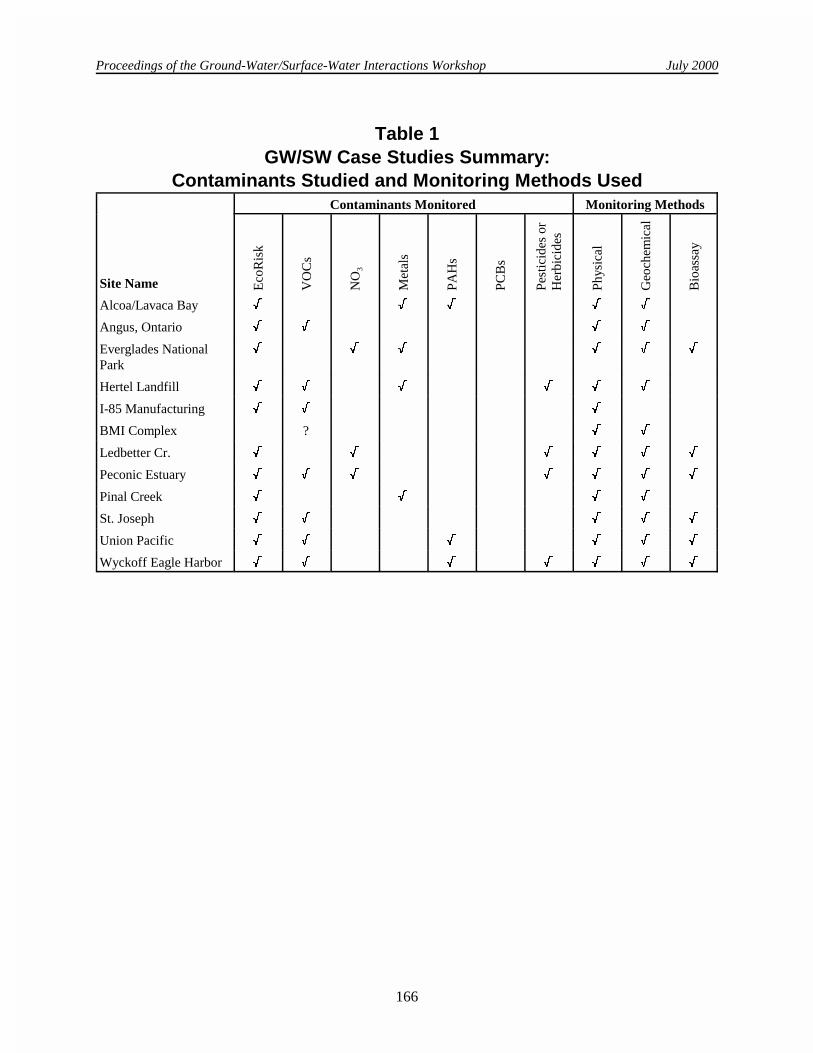
Workshop participants submitted 14 case study summaries of ground water/surface waterinvestigations for inclusion in this report. The purpose of providing these summaries is two-fold. First,to provide a resource for further information on the various monitoring methods. The case studysummaries represent a range of contaminated media and contaminants within different hydrogeologiclandscapes. Contact names are provided for further information on the use of such monitoring methodsand their utility in obtaining the desired site data. The case studies are also provided as part of aninformal assessment of what techniques are and are not commonly used. The following four tablesprovide this assessment.
Table 1 lists the case study sites and the main contaminant types present as well as the type ofmonitoring done at each site (physical, geochemical, or biological). Tables 2, 3, and 4 expand on thetype of physical, geochemical, and biological monitoring being done, to summarize in some detail thetype and number of sites using a given monitoring procedure. The tables include a total for the types ofmethods used and the number of total different places all the methods have been used at. They showthat physical and geochemical methods are about equally distributed in use, but bioassays (and relatedbiological monitoring) are much less widely used at the sites.
This appendix is not meant to be a comprehensive list of sites having ground water/surface waterinteraction and contamination problems, but simply a tabulation of the types of sites which wererepresented through those attending the Workshop, and also a listing of the types of methods whichhave been used in the field when dealing with this type of complex ground water/surface waterinteraction and contamination sites. It is interesting to note that while the most used monitoringmethods are wells and piezometers, that there are many other monitoring options that have been usedat sites where there is a ground water to surface water transition zone.
Proceedings of the Ground-Water/Surface-Water Interactions Workshop July 2000
166
Table 1GW/SW Case Studies Summary:
Contaminants Studied and Monitoring Methods UsedContaminants Monitored Monitoring Methods
Site Name Eco
Ris
k
VO
Cs
NO
3
Met
als
PA
Hs
PCB
s
Pes
ticid
es o
rH
erbi
cide
s
Phy
sica
l
Geo
chem
ical
Bio
assa
y
Alcoa/Lavaca Bay � � � � �
Angus, Ontario � � � �
Everglades NationalPark
� � � � � �
Hertel Landfill � � � � � �
I-85 Manufacturing � � �
BMI Complex ? � �
Ledbetter Cr. � � � � � �
Peconic Estuary � � � � � � �
Pinal Creek � � � �
St. Joseph � � � � �
Union Pacific � � � � � �
Wyckoff Eagle Harbor � � � � � � �

Proceedings of the Ground-Water/Surface-Water Interactions Workshop July 2000
167
Table 2Case Studies Summary of Data Collection Techniques Used
Data Collection Techniques Total Site Names
Current meters 2 Everglades National ParkPinal Creek
Diffusion sampler 1 I-85 Manufacturing
Direct Push Samples 2 I-85 ManufacturingWyckoff Eagle Harbor
Geophysical Measurements 2 Peconic EstuaryWyckoff Eagle Harbor
Geoprobe 1 Wyckoff Eagle Harbor
GW Water level surveys 2 Angus, OntarioWyckoff Eagle Harbor
GW Mini-piezometer 5 Angus, OntarioLedbetter Cr.
Peconic Estuary Pinal Creek
Wyckoff Eagle Harbor
(Continued)...
Ground water monitoring wells 8 Alcoa/Lavaca BayHertel LandfillBMI ComplexLedbetter Cr.
Peconic EstuaryPinal Creek
Union PacificWyckoff Eagle Harbor
Ground water multilevelsampling device
2 Angus, OntarioSt. Joseph
Ground water Waterloo Profiler 1 Angus, Ontario
Ground water piezometers 3 Alcoa/Lavaca BayEverglades National Park
Hertel Landfill
In-stream solute tracer 1 Pinal Creek
In-stream auto sampler 1 Pinal Creek
NAPL studies 3 Alcoa/Lavaca BayUnion Pacific
Wyckoff Eagle Harbor
Potentiomanometer 1 Angus, Ontario
SCAPS survey 1 Wyckoff Eagle Harbor

Proceedings of the Ground-Water/Surface-Water Interactions Workshop July 2000
Table 2Case Studies Summary of Data Collection Techniques Used
Data Collection Techniques Total Site Names
168
Sediment sampling 4 Angus, OntarioI-85 Manufacturing,
Union PacificWyckoff Eagle Harbor
Sediment probe 2 Angus, OntarioLedbetter Cr.
Seepage meters 5 Everglades National ParkLedbetter Cr.
Peconic EstuaryPinal Creek
Wyckoff Eagle Harbor
Slug testing 1 Angus, Ontario
Soil cores onshore 2 Angus, OntarioWyckoff Eagle Harbor
(Continued)...
Soil cores offshore 3 Angus, OntarioSt. Joseph
Wyckoff Eagle Harbor
Streambed temperature survey 2 Angus, OntarioWyckoff Eagle Harbor
Surface water monitoring 2 BMI ComplexWyckoff Eagle Harbor
Time Domain Reflectrometry 1 Angus, Ontario
Tracer 1 Pinal Creek
Velocity and tracer-dilutiongaging
1 Pinal Creek
27 62

Proceedings of the Ground-Water/Surface-Water Interactions Workshop July 2000
169
Table 3Case Studies Summary of Geochemical Techniques Used
Geochemistry Total Site Names
Age-dating of GW 1 Pinal Creek
Alkalinity 2 Hertel LandfillPinal Creek
Ammonia 1 Hertel Landfill
Biochemical Oxygen Demand(BOD-5)
1 Hertel Landfill
Cation/Anion 1 Angus, Ontario
Chemical Oxygen Demand(COD)
2 Hertel LandfillWyckoff Eagle Harbor
Chloride 2 Hertel LandfillWyckoff Eagle Harbor
Chlorophyll 1 Peconic Estuary
CO2 1 Ledbetter Cr.
Ethene, ethane, methane 3 Everglades National ParkLedbetter Cr.
Angus, Ontario
Field chemistry tests 1 St. Joseph
(Continued)...
Field Parameters (pH, Temp.,EH, DO, Elec. Cond.)
9 Alcoa/Lavaca BayAngus, OntarioBMI ComplexLedbetter Cr.
Peconic EstuaryPinal CreekSt. Joseph
Union PacificWyckoff Eagle Harbor
Hydrogen Gas—Dissolved 1 St. Joseph
Isotopes 1 Pinal Creek
Major ions 2 Pinal CreekSt. Joseph
NAPL studies 2 Wyckoff Eagle HarborUnion Pacific
Nitrogen–Dissolved 3 Hertel LandfillLedbetter Cr.St. Joseph
Nitrogen–Total 1 Ledbetter Cr.

Proceedings of the Ground-Water/Surface-Water Interactions Workshop July 2000
Table 3Case Studies Summary of Geochemical Techniques Used
Geochemistry Total Site Names
170
Nutrients 4 Everglades National ParkLedbetter Cr.
Peconic EstuaryPinal Creek
Organic Carbon--Dissolved 2 Angus, OntarioHertel Landfill
Phosphate 2 Hertel LandfillLedbetter Cr.
Radium isotopes 1 Everglades National Park
Radon-222 1 Everglades National Park
Redox-sensitive metals 1 Everglades National Park
Salinity 1 Wyckoff Eagle Harbor
Sediment chemistry 2 Hertel LandfillWyckoff Eagle Harbor
Sulfate 2 Hertel LandfillLedbetter Cr.
(Continued)...
Sulfide 3 Angus, OntarioHertel Landfill
St. Joseph
Total Dissolved Solids 2 Hertel LandfillWyckoff Eagle Harbor
Total Suspended Solids 1 Hertel LandfillWyckoff Eagle Harbor
31 57
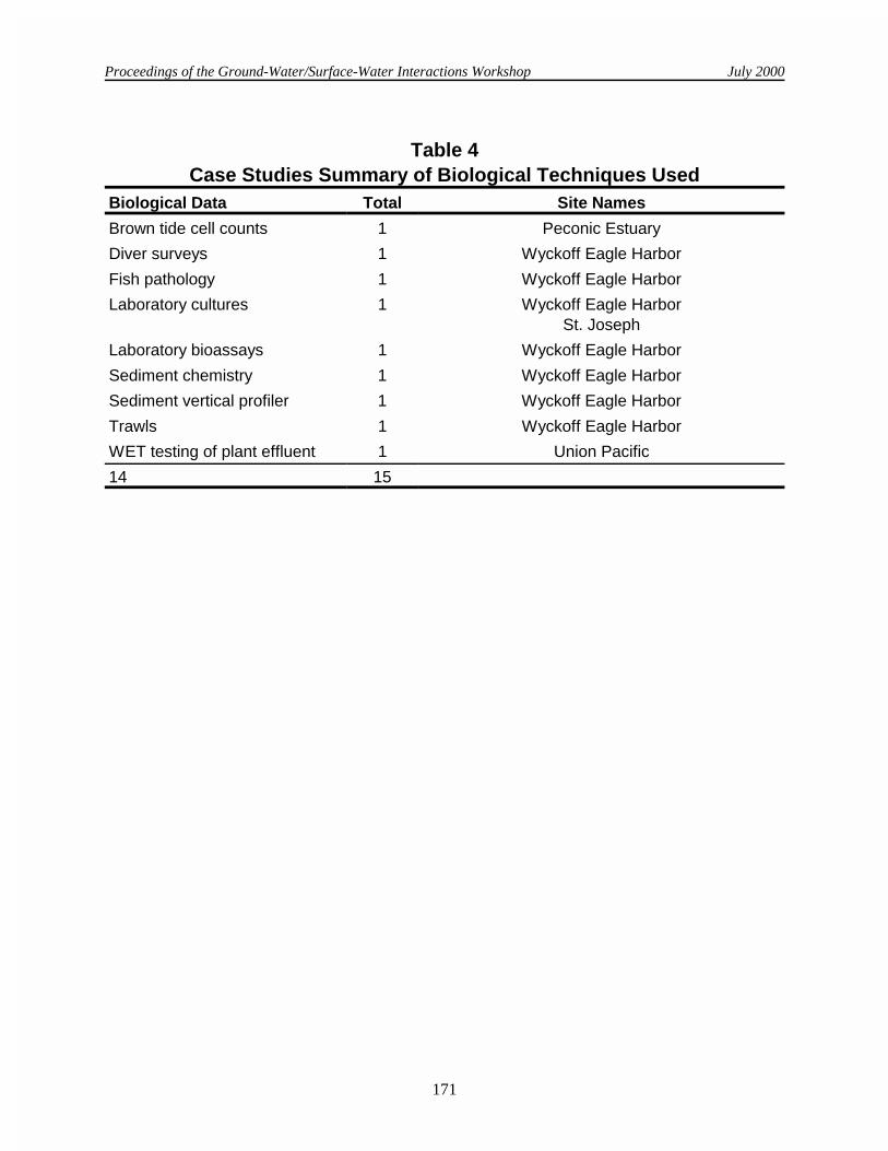
Table 4Case Studies Summary of Biological Techniques Used
Biological Data Total Site Names
Bacteriophages 1 Everglades National Park
Benthic macroinvertebrate 1 Ledbetter Creek
Benthic community analysis 2 Wyckoff Eagle HarborLedbetter Creek
Biofilm colonization chambers 1 Ledbetter Creek
Biomonitoring of plant effluent 1 Wyckoff Eagle Harbor
Proceedings of the Ground-Water/Surface-Water Interactions Workshop July 2000
Table 4Case Studies Summary of Biological Techniques Used
Biological Data Total Site Names
171
Brown tide cell counts 1 Peconic Estuary
Diver surveys 1 Wyckoff Eagle Harbor
Fish pathology 1 Wyckoff Eagle Harbor
Laboratory cultures 1 Wyckoff Eagle HarborSt. Joseph
Laboratory bioassays 1 Wyckoff Eagle Harbor
Sediment chemistry 1 Wyckoff Eagle Harbor
Sediment vertical profiler 1 Wyckoff Eagle Harbor
Trawls 1 Wyckoff Eagle Harbor
WET testing of plant effluent 1 Union Pacific
14 15

Proceedings of the Ground-Water/Surface-Water Interactions Workshop July 2000
172
Case Studies
1) SITE NAME: Alcoa (Point Comfort)/ Lavaca Bay
2) City/State: Point Comfort, Texas
5) Surface Water Body: Lavaca and Matagorda Bays
8)Contaminants:
Ground Water
3) Regulatory Authority: CERCLA
6) Range of Tidal Variation:
0.5-1.5 ft
Hg, PAHs, DNAPL (Hg and tar)
Soil
4) Contact:
Ron GouguetCoastal Resource CoordinatorU.S. EPA, Region 61445 Ross AvenueSuite # 1200Dallas, TX 75202-2733Phone: [email protected]
Gary BaumgartenRemedial Project ManagerU.S. EPA, Region 61445 Ross AvenueSuite # 1200Dallas, TX 75202-2733Phone: [email protected]
7) Risk:Human HealthFish consumption
Creosote compounds, PAHs, Hg
Surface Water
Rarely detected
EcologicalFishBenthosShell fish
Pore Water
Hg, MeHg, PAHs
Sediment
PAHs, Hg
9) Monitoring Methods:
Physical Measurements
Monitoring wells, piezometers,water level surveys, DNAPLstudies
Geochemical Parameters
Field parameters, DNAPLstudies, salinity
Bioassays
Unknown at this time
10) COMMENTS: Contributions of contaminated groundwater appear to be responsible for maintaining Hg and PAHconcentrations in surficial bay sediment above risk based levels of concern. Also, this appears to be thecase for maintaining tissue concentration at levels of concern. The remedy (CERCLA) is expected tocurtail the GW release, remove some sediment and stabilize sources.

Proceedings of the Ground-Water/Surface-Water Interactions Workshop July 2000
173
1) SITE NAME: Angus Ontario
2) City/State: Angus, Ontario, Canada
5) Surface Water Body: Pine River
8)Contaminants:
Ground Water
3) Regulatory Authority: Ontario Ministry ofEnvironment and Energy
6) Range of Tidal Variation:
Not applicable
Chlorinated VOC-tetrachloroethylene
Soil
4) Contact:
Brewster Conant Jr.HydrogeologistDepartment of Earth SciencesUniversity of WaterlooWaterloo, Ontario N2L 3G1Phone: 519-885-1211 x [email protected]
Dr. John A. CherryProfessor of Earth SciencesUniversity of WaterlooWaterloo, Ontario N2L 3G1Phone: 519-885-1211 [email protected]
7) Risk:Human HealthDrinking water (groundwater)Sediment contact
tetrachloroethylene
Surface Water
Rare detections of very lowtetrachloroethylene concentrations
EcologicalBenthic and hyporheic aquaticlife
Pore Water
tetrachloroethylene,trichloroethylene,cis-1,2-dichloroethylene,trans-1,2-dichloroethylene, vinylchloride
Sediment
tetrachloroethylene,trichloroethylene,cis-1,2-dichloroethylene
9) Monitoring Methods:
Physical Measurements
Drivepoint wells, mini-piezometers,Waterloo Profiler and mini-profiler,multilevel GW samplingdevices, soil cores (on and offshore), ground penetratingradar (GPR), time domainreflectometry (TDR),sediment probe (conductance),streambed temperature surveys,water level surveys,potentiomanometer
Geochemical Parameters
Field parameters, dissolvedoxygen, sulfide, cations/anions,ammonia,dissolved organic carbon,chlorinated VOCs (PCE, TCE,DCEs, and VC), ethene,ethane, methane
Bioassays
None

Proceedings of the Ground-Water/Surface-Water Interactions Workshop July 2000
174
10) COMMENTS: Data collected primarily as part of Mr. Conant’s PhD research. Pine River typically flows at 1.5 to 2.9cubic meters per second.

Proceedings of the Ground-Water/Surface-Water Interactions Workshop July 2000
175
1) SITE NAME: Everglades National Park/ Florida Bay
2) City/State:South Florida
5) Surface Water Body: Wetland, estuary, bay
8)Contaminants:
Ground Water
3) Regulatory Authority: 6) Range of Tidal Variation:
<10 cm
NutrientsMetals?
Soil
4) Contact:
Dr. Peter W. SwarzenskiUSGS-GD600 4th Street SouthPetersburg, FL 33701Phone: 727-803-8747 x3072
Dr. Judson W. HarveyUSGS-WRD (NRP)12201 Sunrise Valley DriveMS 430Reston, VA 20192Phone: 703-648-5876
7) Risk:Human HealthInjection wells? Surface Water
Nutrients
EcologicalEutrophication-related issues
Pore Water
NutrientsMetals?
Sediment
NutrientsMetals?
9) Monitoring Methods:
Physical Measurements
Current meters, piezometers,seepage meters
Geochemical Parameter
Radium isotopes, radon-222,CH4, nutrients, redox-sensitivemetals
Bioassays
Bacteriophages
10) COMMENTS: A great overview of USGS projects related to South Florida can be found at http://sflwww.er.usgs.gov/
Proceedings of the Ground-Water/Surface-Water Interactions Workshop July 2000
176
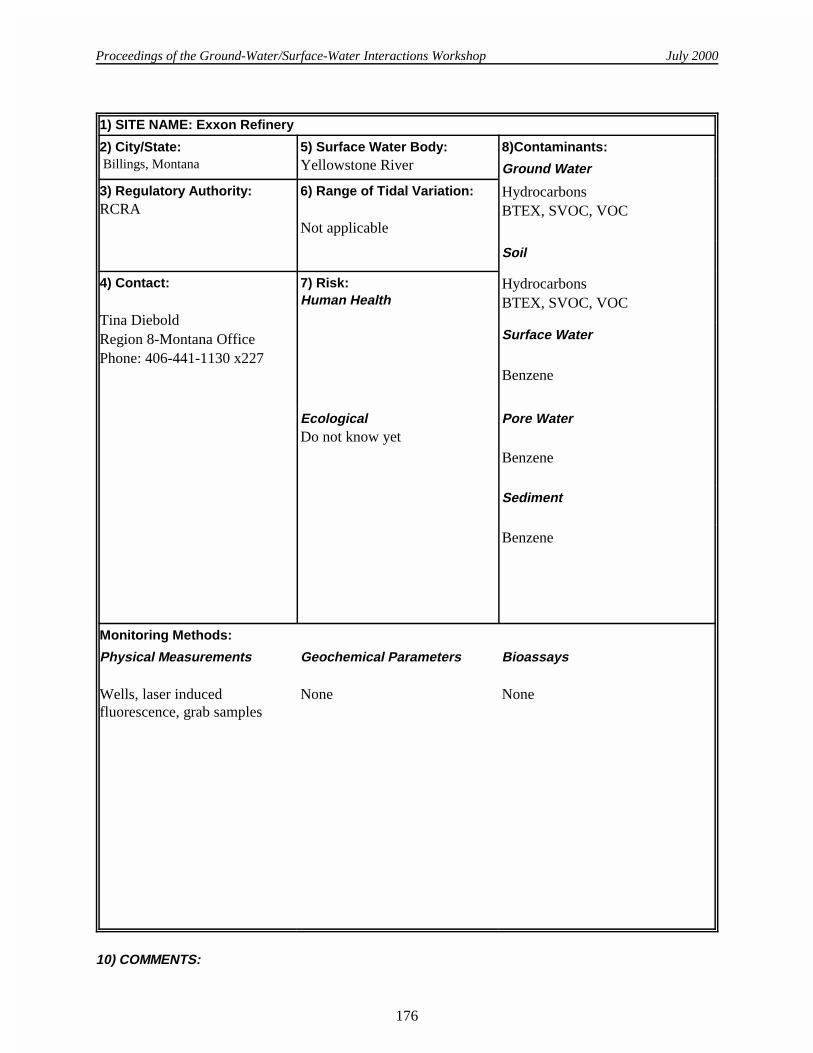
1) SITE NAME: Exxon Refinery
2) City/State: Billings, Montana
5) Surface Water Body: Yellowstone River
8)Contaminants:
Ground Water
3) Regulatory Authority:RCRA
6) Range of Tidal Variation:
Not applicable
HydrocarbonsBTEX, SVOC, VOC
Soil
4) Contact:
Tina DieboldRegion 8-Montana OfficePhone: 406-441-1130 x227
7) Risk:Human Health
HydrocarbonsBTEX, SVOC, VOC
Surface Water
Benzene
EcologicalDo not know yet
Pore Water
Benzene
Sediment
Benzene
Monitoring Methods:
Physical Measurements
Wells, laser inducedfluorescence, grab samples
Geochemical Parameters
None
Bioassays
None
10) COMMENTS:

Proceedings of the Ground-Water/Surface-Water Interactions Workshop July 2000
177
1) SITE NAME: Hertel Landfill Superfund Site
2) City/State: Plattekill, New York
5) Surface Water Body: Wetlands
8)Contaminants:
Ground Water
3) Regulatory Authority: CERCLA
6) Range of Tidal Variation:
Not applicable
Primarily arsenic, chromium, iron,manganeseVOCs and CVOCsPesticides
Soil
4) Contact:
Dean MaraldoHydrogeologistU.S. EPA, Region 2ERRD/PSB/TST290 BroadwayNew York, NY 10007-1866Phone: [email protected]
Sharon TrocherRPMU.S. EPA, Region 2EPA/ERRD/NYRB290 BroadwayNew York, NY 10007-1866Phone: [email protected]
7) Risk:Human HealthTouching or drinkingcontaminated well water oraccidentally ingestingcontaminated soil
Arsenic, chromium, VOCs
Surface Water
Iron, manganese, pesticides
EcologicalPollutants have seeped into on-site wetlands, posing a threat toecologically sensitiveresources, wildlife, or aquaticbiota.
Pore Water
Sediment
Pesticides, metals
9) Monitoring Methods:
Physical Measurements
Monitoring wells, piezometers
Geochemical Parameter
Surface and ground water:phosphate, COD, nitrate-nitrite,TOC, ammonia, alkalinity,BOD-5, TKN, sulfide, sulfate,chloride, TDS, TSS
Bioassays
None
10) COMMENTS: Capping of this 13-acre municipal landfill was completed in the fall of 1998. At this time the primaryCOCs are metals in the groundwater and surface. The 1991 ROD remedy included a pump-and-treatcomponent for groundwater which has been put on hold pending post-cap data evaluation.

Proceedings of the Ground-Water/Surface-Water Interactions Workshop July 2000
178
1) SITE NAME: I-85 Manufacturing and Distribution Center
2) City/State: Spartanburg, South Carolina
5) Surface Water Body: Tributary to Fairforest Creek
8)Contaminants:
Ground Water
3) Regulatory Authority:State Superfund
6) Range of Tidal Variation:
Not applicable
Tetrachloroethylene
Soil
4) Contact:
Judy CanovaProject ManagerSCDHEC2600 Bull St.Columbia, SC 29201Phone: 803- 896-4046canovajl@
columb34.dhec.state.sc.us
7) Risk:Human HealthContactInhalationIngestion
Tetrachloroethylene
Surface Water
Tetrachloroethylene
EcologicalFish Invertebrates
Pore Water
Unknown
Sediment
Pending
9) Monitoring Methods:
Physical Measurements
Diffusion samplers, direct pushsamplers, grab samples
Geochemical Parameters
None
Bioassays
None
10) COMMENTS: The unusual characteristic of this site is the high concentration of tetrachloroethylene observed insurficial samples from the tributary - up to 10 ppm. It is suspected that NAPL is discharging to the baseof the stream based on groundwater quality data. At the location of highest contamination within thestream, there is no visible aquatic life, vertebrate or invertebrate. Contamination persists above ambientwater quality criteria for over half a mile. The length of the discharge coupled with extremetopographic variation reduces possible remedial options for the stream.

Proceedings of the Ground-Water/Surface-Water Interactions Workshop July 2000
179
1) SITE NAME: Kerr-McGee Chemical/ BMI Complex
2) City/State: Henderson, Nevada
5) Surface Water Body: Lake Mead, Colorado River
8)Contaminants:
Ground Water
3) Regulatory Authority:State
6) Range of Tidal Variation:
Not applicable
Ammonium perchlorate
Soil
4) Contact:
Mitch KaplanEnvironmental ScientistU.S. EPA, Region 975 Hawthorne StreetSan Francisco, CA 94105Phone: 415- [email protected]
Doug ZimmermanChief, Bureau of CorrectiveActionNevada Dept. of EnvironmentalProtectionPhone: 775- 687-4670 x3127
7) Risk:Human HealthIngestion
Not analyzed
Surface Water
Ammonium perchlorate
EcologicalUnknown (under investigation)
Pore Water
Not analyzed
Sediment
Not analyzed
9) Monitoring Methods:
Physical Measurements
Monitoring wells, surface watermonitoring
Geochemical Parameters
Field parameters
Bioassays
None
10) COMMENTS:

Proceedings of the Ground-Water/Surface-Water Interactions Workshop July 2000
180
1) SITE NAME: Ledbetter Creek
2) City/State: Murray, Kentucky
5) Surface Water Body: Kentucky Lake Reservoir
8)Contaminants:
Ground Water
3) Regulatory Authority:State of Kentucky
6) Range of Tidal Variation:
Hydroelectric/Flood ControlDam operations result in 2-6 ftchange in water depth at streamsite.
Nitrates, herbicides, pesticides,fecal coliforms
Soil
4) Contact:
Susan P. HendricksHancock Biological Station561 Emma DriveMurray, KY 42071Phone: [email protected]
David S. WhiteHancock Biological Station561 Emma DriveMurray, KY 42071Phone: [email protected]
7) Risk:Human HealthContact
Nitrates, herbicides, pesticides
Surface Water
Nitrates, herbicides, pesticides,fecal coliforms
EcologicalSurface-subsurface microbialcommunitiesSurface-subsurface macroin-vertebrate communitiesFish communityHabitat degradation from highsedimentation/siltation, reducedsurface-subsurface exchange
Pore Water
Nitrates, herbicides, pesticides,fecal coliforms
Sediment
Nitrates, herbicides, pesticides,fecal coliforms
9) Monitoring Methods:
Physical Measurements
Monitoring wells, water tableheights, mini-piezometers,sediment temperature probes,seepage meters
Geochemical Parameters
Dissolved oxygen, turbidity,pH,ORP, specific conductance,NO3+NO2,NH4,SRP, Total N,Total P,SO4,CO2, CH4
Bioassays
Biofilm colonization chambersfor bacterial productivity, activity,and diversity; benthic andhyporheic macroinvertebratecommunity structure.
10) COMMENTS:

Proceedings of the Ground-Water/Surface-Water Interactions Workshop July 2000
181
1) SITE NAME: Peconic Estuary System
2) City/State: Suffolk County, New York
5) Surface Water Body: EPA National Estuary Program-Peconic Estuary System
8)Contaminants:
Ground Water
3) Regulatory Authority: National Estuary Program-Peconic Bay Estuary, SuffolkCounty, New York
6) Range of Tidal Variation:
Approximately 2.5-3.5 ft
VOCs, nitrates, pesticides
Soil
4) Contact:
Ron PaulsenHydrogeologistSuffolk County HealthServices-Bureau of WaterResourcesPhone: 516-853-2220Ronald.paulsen@
co.suffolk.ny.us
Christopher SmithCornell UniversityCooperative Extension MarineProgram LeaderPhone: [email protected]
7) Risk:Human HealthEstuary is receiving water bodyfor groundwater discharges thatcontains pesticides, VOCs andelevated nitrates
Surface Water
VOCs, nitrates, pesticides
EcologicalThe Peconic Estuary Systemhas been subjected to theharmful alga blooms. The HABknown as brown tide(Aureococcus anophaefferens)has plagued the estuary since1985. Excessive nutrients,metals, and possibly pesticidesfrom groundwater seepage arethought to contribute to theonset and proliferation ofHABs in the System
.Pore Water
Nitrates, VOCs
Sediment
9) Monitoring Methods:
Physical Measurements
Installation of monitoring welland mini-piezometers withpercussion drill and hollowaugers; geophysicalmeasurements using loggingtechniques including naturalgamma, induction andresistivity logging; directcontact resistivitymeasurements of bay bottom tomap out groundwater seepagefaces; groundwater seepagemeasurements using time
Geochemical Parameters
Field parameters (conductivity,temperature, dissolved oxygen,chlorophyll, pH); nutrientspecies including inorganic andorganic forms of nitrogen;metals; volatile organic compounds; pesticides
Bioassays
Brown tide (Aureococcusanophaefferens) cell counts

Proceedings of the Ground-Water/Surface-Water Interactions Workshop July 2000
182
10) COMMENTS: The Peconic Estuary System is a large estuary system on Long Island, New York that receivedNational Estuary Status in 1994. Associated with the estuary program are numerous ongoinginvestigations and studies. These investigations include studies on the ecological, chemical andphysical properties of the Peconic Bay Estuary. One property being studied is the effect ofgroundwater seepage on the chemical and biological conditions in the bay. Direct measurements ofgroundwater seepage along with the chemical analysis of coastal groundwater and bay bottom porewater in the estuary are being made. This information is being used to develop a surface water modeland a groundwater model for the estuary system. The modelling results are being used to developedguidelines for nutrient loading to the bay especially as they pertain to chlorophyll and dissolved oxygenlevels in the bay.

Proceedings of the Ground-Water/Surface-Water Interactions Workshop July 2000
183
1) SITE NAME: Pinal Creek Basin, Arizona
2) City/State:Globe, Arizona
5) Surface Water Body: Pinal Creek, Salt River,Roosevelt Lake (reservoir forPhoenix)
8) Contaminants:
Ground Water
3) Regulatory Authority:State- Arizona Dept. ofEnvironmental Quality(WQARF)Federal-CERCLA
6) Range of Tidal Variation:
Not applicable
Dissolved iron, aluminum, copper,manganese, cobalt, nickel, zincpH<4 in some portions of groundwater contamination plume
Soil
4) Contact:Judson HarveyUSGS430 National CenterReston, VA 20192Phone: [email protected]
Martha ConklinDept. of HydrologyUniversity of ArizonaHarshbarger BldgP.O. Box 210011Tucson, AZ, 85721Phone: [email protected]
Christopher C. FullerUSGS345 Middlefield Road, MS465Menlo Park, CA 94025Phone: [email protected]
James Brown USGS520 N. Park AvenueTucson, AZ 85719Phone: 520-670-6671x280 [email protected]
7) Risk:Human HealthProbably minimal. The majorconcern is for the small numberof families living in the northernpart of the basin that withdrawtheir water from wells emplacedin the aquifer. For the most partthe affected wells were movedaway from contaminated areasyears ago. There continues to beconcern about downstreameffects of metal pollution in thebasin on water quality in theSalt River and Roosevelt Lake,although studies to date suggestthat metals are not reaching theLake in appreciable quantities.Remedial actions are beingundertaken to intercept thegroundwater plume.EcologicalLargely unstudied at thislocation and therefore unknown.However, the perennial iswithin the Tonto NationalForest with abundant wildlife.Poor in-stream water qualityand manganese oxide depositson the stream bed doubtless areaffecting aquatic and terrestrialorganisms that use the streamand riparian zone.
Surface Water
Manganese, nickel, cobalt, zinc,aluminumpH generally > 6 in surface water.
Pore Water
Sediment

Proceedings of the Ground-Water/Surface-Water Interactions Workshop July 2000
184
9) Monitoring Methods:
Physical Measurements
Velocity and tracer-dilutiongaging of stream discharge; in-stream solute-tracerexperiments to determinesurface and hyporheic-zonewater exchange; in-streamauto-samplers; USGS minidrivepoint sampler; seepagemeters; stainless-steeldrivepoints; conventionalwells; identification of groundwater source areas using waterstable isotopes; age-dating ofground water using CFCs.
Geochemical Parameters
pH, DO, temperature, alkalinity,major ions, dissolved metals,particulate and colloidal metals,dissolved organic carbon,nutrients
Bioassays
10) COMMENTS: USGS and the University of Arizona have identified natural attenuation processes that remove metalcontaminants due to interactions between surface water and ground water. Hydrologic exchangebetween the stream that receives the contaminated ground water and the hyporheic zone beneath thestream delays the downstream movement of contaminants, and also exposes the contaminants tounique microbial processes that enhance removal of contaminants in the hyporheic zone. USGS andthe University of Arizona have published more than fifteen journal papers and reports on this topic.Interested readers are encouraged to contact the lead scientists listed above for reprints and moreinformation.
Proceedings of the Ground-Water/Surface-Water Interactions Workshop July 2000
185
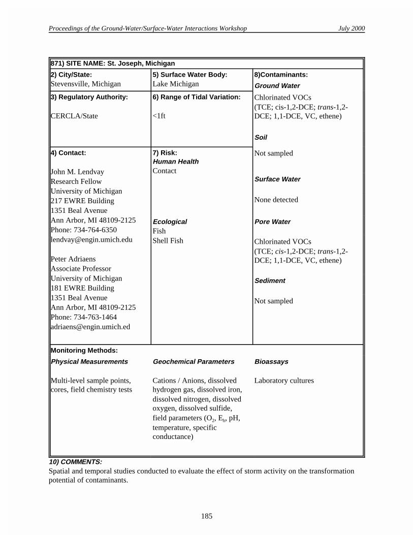
871) SITE NAME: St. Joseph, Michigan
2) City/State:Stevensville, Michigan
5) Surface Water Body: Lake Michigan
8)Contaminants:
Ground Water
3) Regulatory Authority: CERCLA/State
6) Range of Tidal Variation:
<1ft
Chlorinated VOCs(TCE; cis-1,2-DCE; trans-1,2-DCE; 1,1-DCE, VC, ethene)
Soil
4) Contact:
John M. LendvayResearch FellowUniversity of Michigan217 EWRE Building1351 Beal AvenueAnn Arbor, MI 48109-2125Phone: [email protected]
Peter AdriaensAssociate ProfessorUniversity of Michigan181 EWRE Building1351 Beal AvenueAnn Arbor, MI 48109-2125Phone: [email protected]
7) Risk:Human HealthContact
Not sampled
Surface Water
None detected
EcologicalFish Shell Fish
Pore Water
Chlorinated VOCs(TCE; cis-1,2-DCE; trans-1,2-DCE; 1,1-DCE, VC, ethene)
Sediment
Not sampled
Monitoring Methods:
Physical Measurements
Multi-level sample points,cores, field chemistry tests
Geochemical Parameters
Cations / Anions, dissolvedhydrogen gas, dissolved iron,dissolved nitrogen, dissolvedoxygen, dissolved sulfide,field parameters (O2, Eh, pH,temperature, specificconductance)
Bioassays
Laboratory cultures
10) COMMENTS: Spatial and temporal studies conducted to evaluate the effect of storm activity on the transformationpotential of contaminants.

Proceedings of the Ground-Water/Surface-Water Interactions Workshop July 2000
186
1) SITE NAME: Union Pacific Railroad Laramie Tie Plant Site
2) City/State: Laramie, Wyoming
5) Surface Water Body: None- The ContaminantIsolation System preventsreleases to the Laramie River
8)Contaminants:
Ground Water
3) Regulatory Authority: RCRA, CERCLA, State
6) Range of Tidal Variation:
Not applicable
Residuum oil, PAHs,pentachlorophenol (PCP),benzene, ethylbenzene, toluene,xylene, DNAPL
Soil
4) Contact:
Marisa LatadyWyoming Department ofEnvironmental Quality/Soil &Hazardous Waste122 West 25th StreetCheyenne, WY 82002Phone: [email protected]
Felix FlechasUS EPARegion VIII999 18th StreetDenver, CO 80202Phone: [email protected]
7) Risk:Human HealthDermal contactIncidental ingestionInhalation of particulates
PAHs, PCP, dioxin, furans
Surface Water
Not applicable
EcologicalDirect exposures via soilingestionDirect exposures via dermalcontact with soilIndirect exposures via ingestionof contaminated food itemsInhalation of particulate dust(considered less significant theothers described above)
Pore Water
Residuum oil, PAHs,pentachlorophenolbenzene, ethylbenzene, toluene,xylene
Sediment
Not applicable
9) Monitoring Methods:
Physical Measurements
Monitoring wells; piezometers;sediment sampling; monitoringof the containment systems forhydraulic control; DNAPLthickness
Geochemical Parameters
Field parameters
Bioassays
WET testing of the water treatmentplant effluent under an NPDESpermit
Proceedings of the Ground-Water/Surface-Water Interactions Workshop July 2000
187
10) COMMENTS: UPRR operated the Laramie Tie Plant Site for the treatment of railroad ties and other wood preservingoperations on an intermittent basis from 1886 to 1983.The site borders the Laramie River just south ofthe city of Laramie, Wyoming. Waste management practices, such as allowing treated ties to drip dryonto the ground and discharging wastewater generated in the treating process to an unlined surfaceimpoundment, are believed to be the causes of contaminated soils and ground water at the site. Theprimary contaminants identified at the site include creosote, pentachlorophenol and other residuumoils.
Contamination at the site was discovered in 1981, and in 1983 the Environmental Protection Agency(EPA) and UPRR signed a CERCLA Administrative Order on Consent (AOC) to continue theremedial investigation already in progress and to conduct site cleanup. The investigation identifiedcontamination in surface soils and ground water contamination, including the presence of oil in thesubsurface [i.e., Dense Non-Aqueous Phase Liquid (DNAPL)].Some of the early activities conductedby UPRR to address the contamination identified include: 1.In 1983, UPRR decommissioned the facility, including demolition of on-site buildings and
shipment of unused wood treatment materials to another facility. 2.In 1984, UPRR partially closed the unlined Surface Impoundment that received wastewater. The
Surface Impoundment is a regulated unit as defined by the WDEQ/HWRR Chapter 10, Section6(a) .
3.In 1987, UPRR installed the Contaminant Isolation System (CIS) to prevent migration ofcontaminants to the Laramie River. The CIS consists ofrelocation of the Laramie River to anuncontaminated channel; construction of a cutoff wall; installation of a water management systemconsisting of horizontal drain lines along the exterior and interior of the cutoff wall to maintain aninward hydraulic gradient; construction of a water treatment plant to remove dissolvedcontaminants and implementation of a monitoring program to ensure the effectiveness of the CIS.
4.In 1988, UPRR installed ground water extraction wells, referred to as the Morrison ContaminantWithdrawal System (MCWS), outside the western site boundary to address a small area ofcontaminated ground water in Morrison bedrock.
In 1991, EPA and UPRR entered into an AOC under RCRA that required UPRR to conduct aCorrective Measure Study (CMS) to identify long-term remedies for implementation at the site,including pilot tests of various techniques to remove DNAPL from the subsurface.
In 1994, EPA selected the remedy to address contamination at the site. The remedy included continuedoperation of the CIS and MCWS systems, removal of DNAPL using the waterflood oil recoverymethod, covering a portion of the site with topsoil to address contaminated surface soils, installing aRCRA cap over the former Surface Impoundment area, and maintaining restricted access to the site.Nine criteria were selected to evaluate the performance of the final remedy. Detailed descriptions ofthese criteria can be found in EPA's September, 1994, "Final Decision and Response to Comments.
In 1995, the RCRA AOC was amended to require UPRR to submit an application for a RCRA Permitfor post-closure care and corrective action by September 1, 1995. UPRR submitted an application for apost-closure care and corrective action permit on September 1, 1995, and revised that application inMay 1996, August 1997 and March 1998.The amendment to the AOC also required UPRR toimplement the final remedy selected by EPA in 1994. The final remedy was amended in 1995 toinclude the use of a Corrective Action Management Unit (CAMU) to consolidate contaminated
Proceedings of the Ground-Water/Surface-Water Interactions Workshop July 2000
188
concrete debris and soils in the partially closed unlined Surface Impoundment. The CAMU currentlyhas an interim soil cover of six inches.
That portion of the final remedy that requires closure (i.e., installation of a RCRA cap) and post-closure care of the Surface Impoundment, as described in Section A of this Fact Sheet, is deferred toallow implementation and evaluation of phytoremediation, an innovative technology, designed for in-situ remediation of waste, contaminated soils and contaminated ground water. Phytoremediation testplots will be established over a portion of the Surface Impoundment and the western portion of thefacility to determine the effectiveness of this technology. Review of this corrective action program willbe conducted every five (5) years as part of the technical impracticability (TI) determination. The TIdetermination is made when ground water restoration to applicable cleanup standards is unattainablefrom an engineering perspective. If WDEQ determines, based on the five (5) year review process, thatphytoremediation does not meet the remediation criteria specified in the Permit, UPRR will berequired to implement the closure and post-closure care requirements established in the Permit. Thoseportions of the final remedy that are not deferred include continued oil recovery operations in theSurface Impoundment area until all recovery units have achieved the endpoint criteria, andimplementation of the ground water corrective action program.
As of December 1998 UPRR has recovered approximately 1,500,000 gallons of oil from thesubsurface through the waterflood oil recovery method.

Proceedings of the Ground-Water/Surface-Water Interactions Workshop July 2000
189
1) SITE NAME: West Branch Canal Creek, Aberdeen Proving Ground
2) City/State:Edgewood, Maryland
5) Surface Water Body: Wetland and stream
8)Contaminants:
Ground Water
3) Regulatory Authority: CERCLA
6) Range of Tidal Variation:About 2 ft change in stage increek; affects ground-waterflow direction and plumedistribution
Chlorinated VOCsPossible DNAPL
Soil
4) Contact:
Michelle LorahU.S. Geological Survey8987 Yellow Brick RoadBaltimore, MD 21237Phone: 410-238-4301Fax: [email protected]
7) Risk:Human HealthAir transport of VOCs
None
Surface Water
Infrequently detected, lowconcentrations of chlorinatedVOCs
EcologicalAir transport of VOCsPossible exposure of benthicorganisms to VOCs in waterand sediment
Pore Water
Chlorinated VOCs
Sediment
Chlorinated VOCs in wetlandsediment
Monitoring Methods:
Physical Measurements
Nested piezometers, diffusionsamplers, cores, field chemistrytests, salinity, pressuretransducers and tide gage
Geochemical Parameters
VOCs; ethane; ethene;dissolved organic carbon; totalorganic carbon redox species-methane, sulfide, Fe(II)/Fe(III),manganese, dissolved oxygen,nitrate, ammonia; fieldparameters (pH, alkalinity,temperature, conductance,salinity, turbidity); majorcations and anions; selectedtrace metals
Bioassays
Microcosms to measurebiodegradation rates and daughterproducts; DNA/RNA analysis ofmicrobial communities in wetlandsediment
10) COMMENTS: USGS WRIR 97-4171: Report on project results through 1997 available online:http://md.usgs.gov/publications/online.html
Proceedings of the Ground-Water/Surface-Water Interactions Workshop July 2000
190
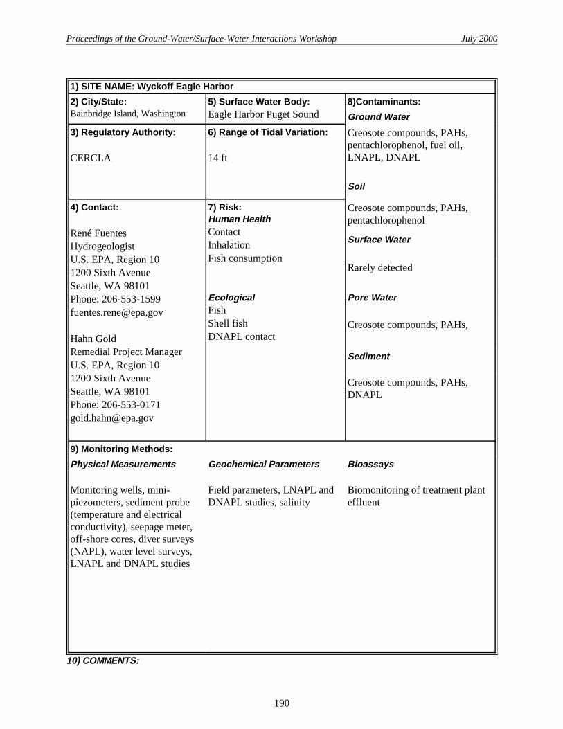
1) SITE NAME: Wyckoff Eagle Harbor
2) City/State:Bainbridge Island, Washington
5) Surface Water Body: Eagle Harbor Puget Sound
8)Contaminants:
Ground Water
3) Regulatory Authority: CERCLA
6) Range of Tidal Variation:
14 ft
Creosote compounds, PAHs,pentachlorophenol, fuel oil,LNAPL, DNAPL
Soil
4) Contact:
René FuentesHydrogeologistU.S. EPA, Region 101200 Sixth AvenueSeattle, WA 98101Phone: [email protected]
Hahn GoldRemedial Project ManagerU.S. EPA, Region 101200 Sixth AvenueSeattle, WA 98101Phone: [email protected]
7) Risk:Human HealthContactInhalation Fish consumption
Creosote compounds, PAHs,pentachlorophenol
Surface Water
Rarely detected
EcologicalFish Shell fishDNAPL contact
Pore Water
Creosote compounds, PAHs,
Sediment
Creosote compounds, PAHs,DNAPL
9) Monitoring Methods:
Physical Measurements
Monitoring wells, mini-piezometers, sediment probe(temperature and electricalconductivity), seepage meter,off-shore cores, diver surveys(NAPL), water level surveys,LNAPL and DNAPL studies
Geochemical Parameters
Field parameters, LNAPL andDNAPL studies, salinity
Bioassays
Biomonitoring of treatment planteffluent
10) COMMENTS:

Proceedings of the Ground-Water/Surface-Water Interactions Workshop July 2000
* Editor’s Note: Mark Henry presented this material at a meeting of the Ground Water Forum in April 2000.
191
Appendix D: MHE Push Point Sampling Tools
by Mark A. Henry*
A new tool and sampling methodology have been devised for collecting pore water samples frombeneath beaches and surface water bodies. The use of this technology enables a single investigator orsmall team to rapidly gather pore water samples at or near the interface between groundwater andreceiving bodies of water. From a research perspective, the information gained in analyzing thesesamples may be very helpful in understanding the geochemical nature of this transition zone and thebiological processes at work.
This methodology has been used very successfully to locate the expression of contaminatedgroundwater venting into several lakes in Michigan. The technique involves the use of an MHE 27-inch push-point sampling device (PP27), ¼-inch outer diameter by F-inch inner diameter Tygontubing, and 50 m5, 100% polyethylene syringes or a peristaltic pump. The PP27 is a rigid F-inchdiameter stainless steel probe that is screened at one end and ported at the other to allow the collectionof pore water with a syringe or peristaltic pump. In this method’s simplest form, the investigator wouldwalk along a beach or in shallow water paralleling the beach, and at periodic intervals push (by hand) adecontaminated PP27 into the sand or sediments with a twisting motion until refusal (usually 6-18-inches). Then the screened zone is exposed and pore water samples are withdrawn at “low-flowsampling” collection rates using a disposable syringe connected by a length of Tygon tubing. Usually,only 30-50 m5 of water withdrawal is necessary to develop this miniature well; this equates toapproximately 20-35 volume exchanges through the PP27 . Subsequently drawn water is usually non-turbid and suitable for dispensing directly into sample containers or instruments. A 3-dimensionalsampling array is possible within the sediments and the water column. The PP27 is easilydecontaminated in the field but if the investigator has several of the inexpensive sampling devices on-hand, sample collection along a transect can be very rapid. When 100% polyethylene syringes areemployed, samples may be collected and stored temporarily within the syringe by placing the full,sealed syringe in a cooler. Once the sample collection has been completed, the investigator can processthe samples in a controlled environment. As an added benefit, it is possible to use the sample-filledsyringes for on-site headspace analysis of VOC’s using a field GC—information that be used to directan investigation in real time. If the syringe is half-dispensed and refilled with air, resealed, andagitated, the headspace in the syringe above a known volume of water can be quickly analyzed.
The Michigan Department of Environmental Quality (MDEQ) uses an enhanced variation of thismethod. As samples are being collected, some of the pore water is immediately dispensed into fieldanalytical equipment for measurement of “stabilization parameters” such as dissolved oxygen, pH,conductivity, redox, and temperature, or analytes such as dissolved iron, sulfide, etc. The MDEQinvestigators were able identify and map the expression of a groundwater plume venting into LakeMichigan and several inland lakes using this methodology and/or these techniques and SCUBA gear.Furthermore, the MDEQ couples its sampling with location information obtained using sub-meteraccuracy global positioning system (GPS) equipment. Plotting the geochemical data onto an accurateGPS representation of the sampling locations and predominant local features produces a precise plumeexpression map. GPS technology allows investigators to reliably relocate previous sampling locationsfor additional study and accurately combine and compare data from multiple sampling events.

Proceedings of the Ground-Water/Surface-Water Interactions Workshop July 2000
192
What follows is found in the MHE PP-27 sampler instruction manual. It is presented as additionalinformation about the sampler and to provide a few practical hints.
MHE PP27" Push-Point Sampling device (Patent Pending) Operators Manual, Ver. 1.02, May 13, 2000
INTRODUCTION
The groundwater/surface water interface has been a research interest of mine for the past decade.This transitional zone is usually rich in biomass and may play a predominant role in the bioattenuationof contaminated groundwater entering surface water bodies. Usually these biologic processes havelimited effectiveness in attenuating highly contaminated groundwater, leaving a plume of parentcontamination and metabolic byproducts that eventually expresses itself in receiving waters—usuallyclassified as non-point sources of pollution because of the uncertainty of the discharge area. Part of theproblem in the detection and study of these plumes is that there were no devices on the market for therapid, discrete collection of pore water samples. Reliance on conventional technology and techniquesto perform a detailed investigation required extensive effort and burdensome equipment.
Through several iterations, I have evolved a simple device for collecting pore water samples frombeneath surface water bodies or the beach areas surrounding them. Pore water sampling using the PP27becomes a simple and efficient process, generating a wealth of information and very little waste. Theeffective working depth is up to 26 inches below the land or sediment surface. If one collectsgroundwater samples in a transect perpendicular to groundwater flow in the suspected area of plumedischarge to an open water body, their analysis yields information about the areal extent ofcontaminant discharge to the water body. At this point, additional sampling can complement the initialdata and provide the information necessary to map the plume expression in both magnitude and arealdistribution. This is becoming increasingly important to regulators as they decide the ecologicalimpacts of discharging contaminant plumes.
Sampling at each location usually takes five minutes, allowing a small crew to collect dozens ofsamples in an afternoon. These samples can be analyzed in the field for real-time information useful indirecting field investigations and research. The work that I have conducted at several contaminationsites indicates that many groundwater plumes discharge in surface water bodies in 2-3 feet of waterdepth—accessible to investigators wearing hip boots or waders. Many plumes, especially light non-aqueous phase liquid (LNAPL) plumes can be delineated by collection of samples in very shallowwater or from under beaches. My initial experience has shown that dense non-aqueous phase liquid(DNAPL) contaminant plumes express themselves in the shallow, near-shore water as well, eventhough the onshore depth of the contaminant mass was deep in the aquifer.
DIRECTIONS
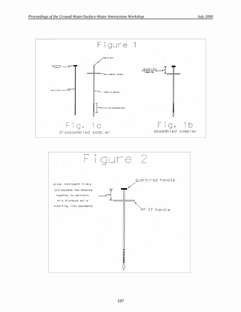
As shown in Figure 1, the PP27 device is a very simple, precisely machined tool consisting of atubular body fashioned with a screened zone at one end and a sampling port at the other. The bore ofthe PP27 body is fitted with a guard rod that gives structural support to the PP27 and prevents pluggingand deformation of the screened zone during insertion into sediments. The PP27 is made of 316stainless steel assuring compatibility with most sampling environments. The screened zone consists ofa series of interlaced machined slots which form a short screened zone with approximately 20% openarea.

Proceedings of the Ground-Water/Surface-Water Interactions Workshop July 2000
193
Operation of the PP27 is not difficult. Simply hold the device in a manner that squeezes the twohandles towards each other to maintain the guard rod fully inserted in the PP27 body during theinsertion process (as shown in Figure 2). Holding the device in this manner, push the PP27 into thesediments or beach to the desired depth using a gentle twisting motion. When the desired depth orrefusal is reached remove the guard rod from the PP27 body without disturbing the position of thedeployed sampler. Once the guard rod has been removed from the PP27, it SHOULD NOT bereinserted into the device until the bore of the PP27 has been thoroughly cleansed of all sand, silt, etc.
Attach a syringe or (peristaltic) pump to the PP27 sample port (see Figure 3) and withdraw water ata low-flow sampling rate (50-200 m5/min.). Once non-turbid aliquots have been withdrawn,representative samples can be collected for on-site and off-site analysis.
HELPFUL HINTS, INFORMATION, AND CAUTIONS
• Multiple depths can be sampled in one hole if samples are collected from deepest to shallowest.Insert the sampler using a twisting motion until you reach refusal. Remove the guard rod. Do notpush the sampler further into the sediments once the guard rod has been removed as thismay damage the screened zone and plug the PP27 with sediment. Once sampling has beencompleted at this deepest depth, the PP27 can be partially pulled from the hole to a new samplingelevation. Remember not to insert the PP27 into the sediments without the guard rod inserted toprevent screened zone damage. Alternately, multiple holes can be used to collect samples frommultiple depths at a particular sampling location. It is recommended that some type be device beused to prevent lateral movement and slippage of the PP27 as sampling is conducted near the topof the hole (see Figure 3). This offsets the leverage of the instrument and reduces holedegeneration. MHE offers an 8-inch diameter., heavy-duty steel sampling platform engineered forprecise sampling depth requirements of field research. A plate of steel with a 3/16-inch diameter.hole through its center would serve the fundamental purpose of maintaining a rigid hole opening .If repeated shallow sampling is to be conducted, it may be more convenient to use a shortersampler (MHE - PP15”).
• If you wish to reuse the PP27 sampler at a particular sampling location and want to clean the borequickly while you’re there so that the guard rod may be safely reinserted, you can use a syringefilled with surface water or deionized water to backflush the bore several times before reinsertingthe guard rod. Use at least 100 m5 of water. If you have too much trouble reinserting the guard rod(e.g., due to grit), it will be necessary to use the standard cleaning procedures with cleaning rodand soap solution.
• If the screened zone of the PP27 becomes plugged while inserted in the sediments, it is frequentlypossible to hydraulically/pneumatically shock the screened zone free of adhering material while itis inserted into the sediments. Attach a large-volume syringe to the sampling port. In a quickmotion, pull the syringe plunger most of the way back (creating a vacuum) and then immediatelyrelease the plunger—the plunger will slam to a neutral position, sending a shock wave through thebore of the PP27 and may alleviate the problem.
• The PP27 can be used as a piezometer to determine the static head of the groundwater and hence,the potential direction of groundwater movement. To do this, a tube is connected to the sample portas shown in Figure 5. A continuous stream of water is established from the syringe (or pump) tothe screened zone by pumping out any air remaining in the PP27and tubing. When the tube is

Proceedings of the Ground-Water/Surface-Water Interactions Workshop July 2000
194
disconnected from the syringe, the static water level in the tube will represent the static water levelat the depth that the screened zone occupies.
• It is frequently possible to push the PP27 through thin lenses of low-permeability material andcollect samples from below them and gather valuable geochemical samples. At many of the siteswhere the PP27 has been used, sampling from just below a layer of fine sand, silt, or clay, oneoccasionally encounters seemingly large pockets of gas that seem to have coalesced and collectedunder this less permeable stratum. Analysis of these pockets may provide additional insight topredominant biological processes. It may true that the concentration of volatile organic compounds(VOCs) in the groundwater has equilibrated with these bubbles (i.e., steady state), which meansthat their presence in a sampling stream or syringe would not significantly affect the concentrationof dissolved VOCs. In fact, if one assumes that steady-state conditions exist, the concentration ofVOCs in the bubbles is directly related the concentration in the surrounding groundwater. Analternate condition may exist if the groundwater is supersaturated with bacterial metabolic wastegases and the negative pressure exerted by the pump (or syringe) is initiating a degassing ofdissolved gases from the groundwater. In this instance, VOCs would partition from thegroundwater to the bubbles as they are formed in the sampling tubing (this is fairly evident ifoccurring). The consequence is that part of the dissolved contaminant mass has partitioned into thegas phase; unless the gas-phase is captured, quantified, and accounted for, the native VOCconcentration of the groundwater is not reflected by analysis of the groundwater alone. If thiscondition exists, the degassing effect can be minimized by decreasing the sampling rate to a ratemore easily yielded by the sampled formation. With experience, it is easy to distinguish which ofthese conditions (or combination of conditions) exist and to what extent they affect sample quality.
• The internal volume of a PP27 is approximately 1.5 m5. A 50 m5 syringe full of distilled water,decontamination water, methanol, etc. will push about 33 volumes through the bore.
• When straightening the screened zone it is sometimes helpful to wash out the bore of the deviceand then insert the guard rod or the cleaning rod to the area of the bend in the screened zone.Gently unbend the portion of the screened zone nearest the rod and carefully advance the rod to thenext bend. After the rod has been fully inserted into the screened zone perform the final screenedzone straightening fine-tuning until the guard rod slides freely through it.
• If the sampling port of the PP27 is above the static level of the water body, each time you removethe syringe or pump from the PP27 sampling port, air will fill the bore of the PP27 allowing thewater level in the bore to reach its static head. To avoid this plug of air from entering thesubsequent syringe, attach a clamp adapter and or a three-way valve between the sampling port andthe syringe or pump inlet as shown in Figure 7.
• I have conducted dye tests by injecting concentrated uradine dye under a perforated 1.5-footdiameter disk through which the PP27 was inserted 3-12-inches into sediments. The goal of thesetests was to determine whether or not surface water and dye is drawn into samples collected in nearsurface sediments (i.e., whether a cone of depression is formed). The results indicated that nosurface water is drawn into samples even though sampling was conducted with a peristaltic pumpat a rate of 600 m5/min.
• I usually couple my field investigations with GPS location of the sampling point. If conditionspermit, a pin flag can be placed at the sampling point for later location by GPS. I usually use sub-

Proceedings of the Ground-Water/Surface-Water Interactions Workshop July 2000
195
meter grade GPS for this surveying; GPS can then be used to relocate previously sampled pointeven if certain site physical characteristics have changed (eroding shorelines, etc.).
• Sampling by syringe has many advantages. This is my preferred field method due to its simplicityand versatility. It is useful to be able to collect several 50 m5 syringes full of groundwater, storethem on ice, and perform the sample transfer to a VOA vial, etc. under more controlled conditions.To transfer sample to a VOA vial, place the end of the transfer tube (Figure 8) to the bottom of theVOA vial. Dispense sample into the VOA vial and slowly withdraw the transfer tube from the vialmaintaining the mouth of the transfer tube just below the sample surface. When the transfer tube isalmost out of the vial, continue to dispense sample and leave an “anti-meniscus” of sample abovethe rim of the vial. Add several drops of HCl (which will displace a few drops of sample) and cap.If VOC samples are to be collected and stored temporarily in a syringe, I recommend using 100%polyethylene (“two piece”) syringes such as those made by Henke Sass Wolf GMBH (NormJect,50 m5)) configured as shown in Figure 8. From personal experience I have found that smallamounts of aromatic compounds (BTEX) can leach from the rubber parts of the rubber-tippedplunger found in common medical syringes. Rubber-tipped plunger syringes have less side-wallresistance and work much smoother than the 100% polyethylene syringes so I use medical syringesfor “development” of the PP27. Standard medical syringes also work well for collecting samplesfor non-VOC analysis. I utilize handheld meters for pH, conductivity, redox, dissolved oxygen, etc.One can dispense sample from the syringe into these types of instruments for field measurements.
• The 50 m5, 100% polyethylene syringes mentioned above can be purchased directly from MHE,configured with tubing as was the example syringe included with your order, or customized to suityour individual needs. If you would to make your own, the syringes that I am currently using arepurchased from National Scientific Company. The tubing is Tygon ¼-inch outer diameter and F-inch inner diameter. Be sure to use some type of clamp at the tubing mouth to ensure a good seal atthe sampler port.
• Headspace GC analysis of VOCs can be easily accomplished using 100% polyethylene syringes.Dispense all but 20 m5 of the sampled groundwater from the syringe. Refill the syringe to the 40m5 mark with ambient air (and heat the syringe in a water bath if desired) as shown in Figure 9.Insert a GC syringe needle through the transfer tube into the syringe headspace and withdraw asample for GC analysis.
• Occasionally a small amount of sand and silt is withdrawn into the syringe or pump samplingstream, even after proper development of the PP27. This may be due to the nature of the geologicformation. This fine material is probably already at equilibrium with the surrounding groundwaterand should not influence analysis of VOCs in the groundwater sample. The sample can betransferred to its shipping container without this silt if the syringe is dispensed in a way that letsthe solid material settle out in the syringe and not carry over to the shipping vial.
• The PP27 has been used very successfully for underwater investigations using SCUBA equipmentand a series of 100% polyethylene syringes. Once again, GPS equipment was used for location ofthe position that the divers collected groundwater samples of contaminant plume expression in thelake. Underwater notes (temperature, depth, observations, etc.) can be written directly on thesample syringes if they are pre-prepared with a strip of Scotch Magic Transparent Tape applieddown the syringe body and writing is done with a soft pencil.
Proceedings of the Ground-Water/Surface-Water Interactions Workshop July 2000
196
• The PP27 may be used to inject nutrients or dyes into the sediments for field trials of biologic orgeochemical testing or tracing groundwater paths. Simply insert the PP27 to the desired depth andafter the guard rod has been removed, connect a syringe or pump and slowly inject the desiredfluid into the sediments, perhaps followed by a small amount of native groundwater to flush theinstrument.
• These devices can be dedicated as semi-permanent underwater monitoring devices. If a PP-27 isinserted to the desired depth through a plate (such as the sampling platform mentioned earlier) thatcan lock the sampler at the correct insertion depth, a vinyl cap can be placed over the mouth of thesampler, and the sampler can be dedicated to that location so that future samples can be withdrawnwhen desired.
• It has been useful to carry several samplers in “quivers” made of 2-inch PVC tubing: one tube for10-15 clean and assembled samplers, and one tube for used samplers and their separated guardrods. This arrangement protects both the investigators and the instruments.
I hope that users will find many useful and innovative uses for this device. If you have other helpfulinformation, uses, and advice concerning these samplers, please write or e-mail suggestions to me forinclusion in future manual revisions. I will be forming a website soon, and posting much of my GSIresearch with links to as much GSI field research and related topics as I can find.Thanks.
Mark HenryMHE Products3371 Sherman Rd.East Tawas, MI 48730Phone: 517-362-5179 or 517-393-0948e-mail: [email protected]
Proceedings of the Ground-Water/Surface-Water Interactions Workshop July 2000
197

Proceedings of the Ground-Water/Surface-Water Interactions Workshop July 2000
198

Proceedings of the Ground-Water/Surface-Water Interactions Workshop July 2000
199

Proceedings of the Ground-Water/Surface-Water Interactions Workshop July 2000
200