proceedings of - nasa · general electric ge90, pratt & whitney pw4000 or rolls-royce trent 800...
TRANSCRIPT

This material is declared work of the U.S. Government and is approved for public release; distribution is unlimited. 1
Proceedings of ASME Turbo Expo 2019: Turbomachinery Technical Conference and Exposition GT2019
June 17 - 21, 2019, Phoenix, Arizona, USA
GT2019-91539
NASA’S ROLE IN GAS TURBINE TECHNOLOGY DEVELOPMENT: ACCELERATING TECHNICAL PROGRESS VIA COLLABORATION BETWEEN ACADEMIA,
INDUSTRY, AND GOVERNMENT AGENCIES
Kenneth L. Suder National Aeronautics and Space Administration, Glenn Research Center
Cleveland, Ohio, USA
ABSTRACT Given the maturity of the gas turbine engine since its
invention and also considering the limited and flattened level of
resources expected to be allocated for NASA aeronautics
research and development, we ask the question are NASA
technology investments still needed to enable future turbine
engine-based propulsion systems? If so, what is NASA’s unique
role to justify NASA’s investment? To address this topic, we
will first review the accomplishments and the impact that NASA
Glenn Research Center has made on turbine engine technologies
over the last 78 years. Specifically, this paper discusses NASA’s
role and contributions to turbine engine development, specific to
both 1) NASA’s role in conducting experiments to understand
flow physics and provide relevant benchmark validation
experiments for Computational Fluid Dynamics (CFD) code
development, validation, and assessment; and 2) the impact of
technologies resulting from NASA collaborations with industry,
academia, and other government agencies. Note that the scope
of the discussion is limited to the NASA technology
contributions with which the author was intimately associated,
and does not represent the entirety of the NASA contributions to
turbine engine technology. The specific research, development,
and demonstrations discussed herein were selected to both 1)
provide a comprehensive review and reference list of the
technology and its impact, and 2) identify NASA’s unique role
and highlight how NASA’s involvement resulted in additional
benefit to the gas turbine engine community.
Secondly, we will discuss current NASA collaborations that
are in progress and provide a status of the results. Finally, we
discuss the challenges anticipated for future turbine engine-
based propulsion systems for civil aviation and identify potential
opportunities for collaboration where NASA involvement would
be beneficial. Ultimately, the gas turbine engine community will
decide if NASA involvement is needed to contribute to the
development of the design and analysis tools, databases, and
technology demonstration programs to meet these challenges for
future turbine engine-based propulsion systems.
1.0 INTRODUCTION NASA Glenn Research Center (GRC) has played a
significant role in gas turbine engine technology development
since its inception in 1940 as the Aircraft Engine Research
Laboratory. In 1942 the research center became a part of the
National Advisory Committee for Aeronautics (NACA) and in
1958 became the NASA Lewis Research Center. More recently,
in 1999, it was officially renamed as the NASA John H. Glenn
Research Center at Lewis Field. To represent the research and
development performed by these research laboratories, the
author will refer to them collectively as NASA Glenn Research
Center (GRC), irrespective of year the work was performed.
Since the patent of the Whittle Engine in 1930, there has been
significant progress in the propulsive and thermal efficiency
which has resulted in significant reductions in TSFC (thrust-
specific fuel consumption), as shown in Figure 1 and Reference
[1]. NASA GRC has had a direct role in these aircraft propulsion
system improvements through concept development, component
testing, analysis, and model development for aircraft engine
inlets, fans, compressors, combustors, turbines, and nozzles.
Under its charter, NASA Aeronautics Research Mission
Directorate (ARMD) does not make, sell, or purchase aircraft
engines, but rather NASA’s ARMD works independently, as
well as with the engine community and other government
agencies to develop technologies for the present and the future
that enable safer, more reliable, capable, and efficient aircraft
with minimal harmful impact on the environment. It is important
to note that Figure 1 indicates further fuel burn reductions are
attainable, even for the modern Boeing 777 (equipped with
General Electric GE90, Pratt & Whitney PW4000 or Rolls-
Royce Trent 800 engines). It is also clear that overall efficiency
is increased most effectively by simultaneous improvements in
thermal efficiency (i.e. core engine technologies) and the
propulsive efficiency (propulsor technologies). Given these turbine engine technology advancements
(shown in Figure 1) and also considering NASA aeronautics
resources are limited, we ask the questions: Are NASA
technology investments still needed to enable future turbine
https://ntrs.nasa.gov/search.jsp?R=20190026567 2020-03-21T18:09:49+00:00Z

This material is declared work of the U.S. Government and is approved for public release; distribution is unlimited. 2
engine-based propulsion systems? If so what is NASA’s
unique role? To discuss this topic, we will look at the
accomplishments and the impact that NASA GRC has made on
turbine engine technologies for the last 78 years from the narrow
perspective of this author, based on his vision of NASA’s roles
and responsibilities. From this author’s perspective NASA’s
primary roles and responsibilities are to a) challenge and inspire
students to pursue careers in science and technology, b) set
aggressive, yet achievable goals for future generation aircraft
that improve performance, safety, and impact on the
environment, c) invest in enabling new technologies with
potentially high benefit that industry alone would not invest and
d) utilize public funds efficiently to develop, demonstrate, and
document technologies that benefit the U.S. gas turbine
community and all humanity. Critical to these endeavors is the
establishment of successful teams and collaborative efforts to
understand the flow physics via experiment and analysis, to
demonstrate the learning via rig and component testing in a
relevant environment, and enhance and validate the design and
analysis tools to provide confidence for future missions.
To address the questions of why NASA and what does
NASA contribute that is unique, we will review: 1) NASA’s role
and contributions to turbine engine development from early days
of inception to present day, 2) NASA’s role in validation
experiments and Computational Fluid Dynamics (CFD) code
development, 3) NASA’s collaborations with academia, 4)
NASA’s collaborations with other Government agencies, and 4)
NASA’s collaborations and technology demonstrations that are
making their way into products. The scope of the discussion is
limited to the NASA technology contributions with which the
author was intimately associated and is heavily slanted toward
compressor technology development and does not represent the
entirety of the NASA contributions to turbine engine technology.
The specific research, development, and demonstrations
discussed herein were selected to both 1) provide a
comprehensive review and reference list of the technology and
its impact, and 2) identify NASA’s unique role and highlight
how NASA’s involvement resulted in additional benefit to the
gas turbine engine community. Then we will discuss the future
challenges for aviation and discuss potential areas for future
collaborations, followed by a summary and concluding remarks.
2.0 BACKGROUND: NASA’S ROLE FROM 1940’S-1980’S
2.1 Early Years 1940s – 1960s.
NASA GRC took a leading role in component development
in its Compressor and Turbine Division during the 1940s and
1950s. Many single-stage and multistage compressor tests were
conducted at the NASA GRC Engine Research Building (ERB),
where various design parameters such as blade pressure ratio,
aspect ratio, and solidity, were varied to develop an
understanding of the trade space to improve fan and compressor
performance and operability. The culmination of this early
period of compressor testing at GRC was published as a series of
classified reports in 1956 and eventually declassified and
republished in 1965 as “Aerodynamic Design of Axial-Flow
Compressors,” NASA SP-36 [2]). A similar publication entitled
“Turbine Design and Application”, NASA SP-290 summarized
the turbine technology during this period [3]. These NASA
publications [2] and [3] have provided great value to the
compressor and turbine design community for many years and is
still considered an authoritative publication on multistage axial
turbomachinery design theory and practice.
Figure 1. Comparison of historical engine thermal (ηth) and effective propulsion (ηp) efficiency improvements. BPR is bypass ratio; LTO, landing and takeoff; and ηtr, transmission efficiency. Effective propulsion efficiency is the product of the propulsor efficiency (ηpr) and the transmission efficiency (ηtr). (From A.H. Epstein [1].
Figure 2. Inflation-corrected oil prices, 1945 to 2005 [4].
2.2 1970s – 1980s
Interest in aircraft fuel efficiency increased dramatically in
the 1970s because of the sharp rise in jet fuel prices, largely
attributed to the oil embargo by OPEC countries in 1973. Figure
2 shows the inflation-corrected price of oil for the 1945 to 2005
timeframe. In response to this rapid increase in fuel prices,
NASA established the Aircraft Energy Efficiency (ACEE)
Program in 1975. The goal of the program was to accelerate the
development of various aeronautical technologies that would
make future transport aircraft up to 50% more fuel efficient. The
baseline engines used for this goal were the Pratt & Whitney
(P&W) JT9D-7A and General Electric (GE) CF6-50C. The most
notable ACEE projects related to engine technology, that were

This material is declared work of the U.S. Government and is approved for public release; distribution is unlimited. 3
led by NASA GRC [4], were the Energy Efficient Engine (E3)
Project and the Advanced Turboprop Project.
The E3 Project goals were to design a new engine to 1)
reduce TSFC by 12%, 2) reduce TSFC performance
deterioration by 50%, 3) reduce direct operating costs by 5%, 4)
meet Federal Aviation Administration (FAA) noise regulations,
and (5) meet EPA then-proposed emissions standards as
described by Ciepluch et al., [5]. Under the E3 Project from 1975
to 1984, NASA invested approximately $200M in contracts to
General Electric (GE) and Pratt & Whitney (P&W). The E3
Project achieved higher propulsive efficiency by using a low-
pressure-ratio fan and higher thermal efficiency by using higher
overall pressure ratio, higher turbine inlet temperatures, and
improved component efficiencies. Specifically, the GE E3 effort
included a 10-stage, 23:1 pressure ratio compressor, a highly
efficient two-stage high-pressure turbine (HPT) and five-stage
low-pressure turbine (LPT), and component efficiencies that
were significantly above the previous state of the art. Along with
increased cycle temperatures, reduced turbine cooling flows
were achieved through a combination of materials development
and cooling concept improvement – see Davis and Stearns [6].
Many engine core technologies developed under the E3 project
were introduced into engine products into the 1990s and beyond.
Specifically, GE’s large GE90 engine which powers the Boeing
777 aircraft, utilizes a core that was derived from the
technologies developed under the E3 Project.
The Advanced Turboprop Project’s objective was to
investigate incorporating large, unducted propellers as the main
propulsor for high-subsonic (Mach number, M approximately
0.8) commercial aircraft with a goal of 20-30% reduction in fuel
burn relative to current engines. The challenge was to enable
highly efficient turboprop operation at Mach 0.8 flight speeds
and higher altitude flight as well as to mitigate the noise issues
inherent to unducted configurations, having no nacelle to shield
and absorb radiated noise. The technical solution to both the
noise and high-speed efficiency problems was to use a swept
blade geometry to provide a lower tip Mach number for a given
flight speed [4]. Although much progress was made on the
development of a viable propfan through both the
NASA/Allison/Pratt & Whitney/Hamilton Standard single
rotation concept and the later counterrotating GE “unducted fan”
(UDF) concept (Figure 3), various factors kept these concepts
from coming to fruition in the market. First, potential negative
public perception of propeller engine architectures made the
airframe manufacturers reluctant to deviate from their
established commitment to turbofan engines, despite the large
benefits in fuel burn reduction. Perhaps more importantly, as
shown in Figure 1, fuel prices by 1986 had retreated back to
nearly pre-1970 values in inflation-adjusted terms. This greatly
reduced the urgency for the airline industry to adopt a radical
change in engine architecture and ended heavy NASA’s heavy
investment in unducted configurations by the late 1980s. The
idea would however return in the NASA Subsonic Fixed Wing
and Environmentally Responsible Aviation (ERA) projects in the
mid-2000s coincident with another rapid increase in fuel prices.
Figure 3. General Electric unducted fan engine. (From http://www.b-domke.de/AviationImages/Rarebird/0809.html. Copyright © 2001–2012 by Burkhard Domke. Used with permission.)
3.0 NASA’S ROLE IN VALIDATION EXPERIMENTS AND FUNDAMENTAL FLOW PHYSICS FOR COMPUTATIONAL FLUID DYNAMICS DEVELOPMENT
Throughout NASA Glenn Research Center’s history, the use
of the Center’s unique experimental capabilities for compressor
and turbine testing and the emphasis on providing return on
investment to the Nation on its taxpayer-funded research has
resulted in the production of open experimental datasets. In the
1970s and 1980s GRC produced a number of compressor
datasets that have been used by the turbomachinery community
as a basis for the validation and development of turbomachinery
analysis tools, including the growing field of computational fluid
dynamics (CFD) codes. Laser Doppler Velocimetry (LDV) was
customized to measure the axial and tangential velocity inside
the rotating passages of transonic compressors. The transonic
fan NASA Rotor 67 was the first major dataset acquired with a
single-channel LDV, which captured the shock and wake
structure in an isolated transonic fan [7, 8, 9, and 10].
Subsequently, NASA Stage 67 (Rotor 67 + Stator 67) was the
first dataset that captured the unsteady fan rotor/stator blade row
interactions with the same single-channel LDV system [11 and
12].
Perhaps the most comprehensive and widely utilized of the
NASA datasets is the NASA Rotor 37 data set, having been the
basis for the 1994 ASME/IGTI Blind CFD code assessment
exercise. This was a period when CFD RANS/URANS codes
had limited access to data depicting the flow field in the rotating
passages of high speed (compressible) turbomachinery to use for
code validation and model development. Building upon
NASA’s experience acquiring data in NASA fan rotor 67 with a
single velocity component system, NASA designed and
developed the first laser anemometer measurement system (early
1980’s) that acquired axial and tangential velocities
simultaneously inside the rotating passages of a transonic
compressor. NASA Rotor 37 has an extensive set of
aerodynamic probes and LDV data across the rotor operating
range from maximum flow to near-stall conditions at 60% speed
(fully subsonic), 80% speed (transonic), and 100% design rotor

This material is declared work of the U.S. Government and is approved for public release; distribution is unlimited. 4
speed (fully supersonic in the rotor frame of reference). Detailed
laser anemometer measurements were acquired at high flow,
design flow, and near stall flow conditions at streamwise and
radial planes shown in Figure 4. The data are best summarized
in [13, 14, and 15] and the blade design and geometry is provided
by Reid and Moore [16].
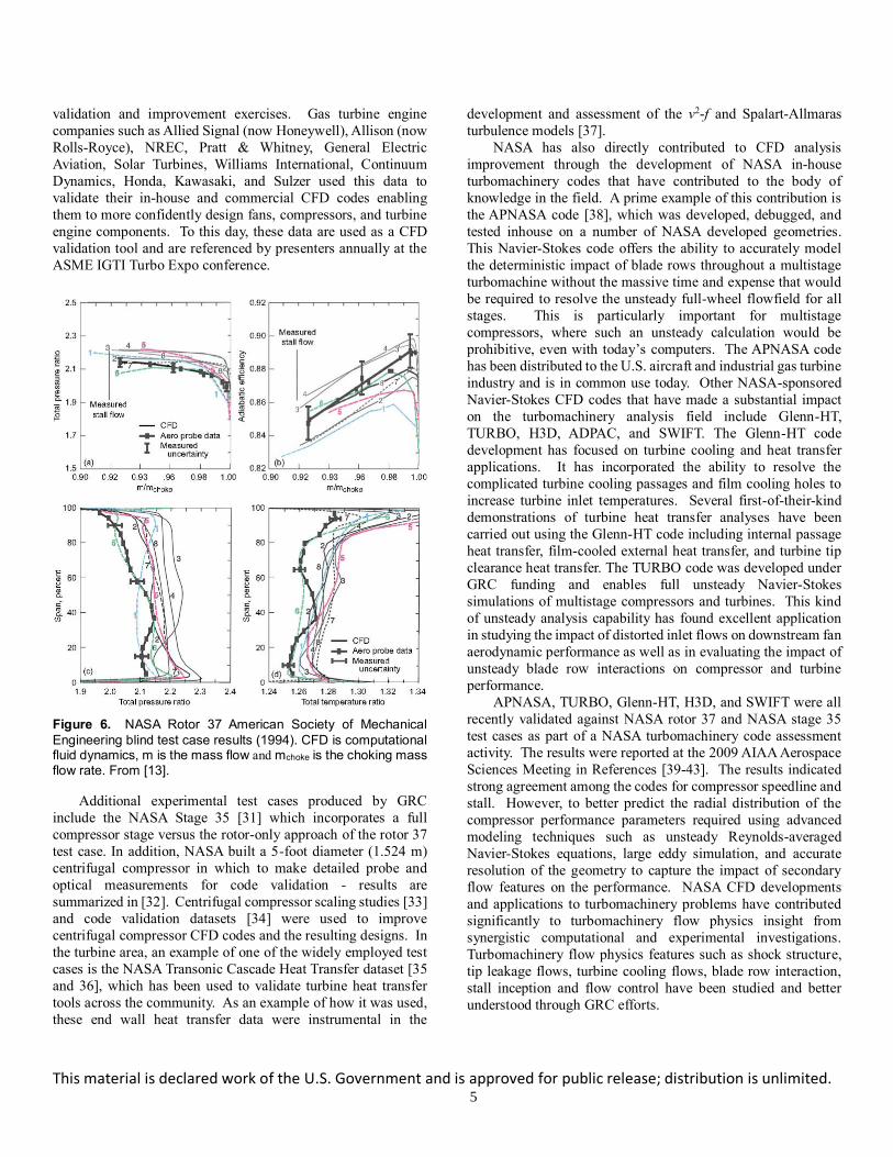
Figure 4. NASA Rotor 37 laser anemometer and aero probe survey locations. From [13].
Figure 5. NASA Rotor 37 Laser Doppler velocimetry data – contours of relative Mach number at design speed and near stall operating conditon: a) 70% span stream surface and b) 95% span stream surface. The red dashed line indicates the tip leakage vortex trajectory. From [13] and [14].
Gas velocity measurements acquired with this laser-based
non-intrusive optical instrumentation were used to study the flow
physics associated with the shock / rotor tip clearance flow, the
shock / boundary layer interactions within the rotor, and wake
decay characteristics downstream of the rotor. An example of
the measurement detail is provided in Figure 5, which shows the
shock boundary layer interaction at 70% span and shock/tip
leakage vortex interaction at 95% span for a 0.5% span rotor tip
clearance. The attributes of the CFD codes that participated in
the ASME blind test case are listed in Table 1. A summary of the
ASME blind test case aerodynamic performance results is
presented in Figure 6, which compares the NASA Rotor 37
experimental and CFD results of overall performance at 100%
design speed as well as the radial distribution of pressure ratio,
temperature ratio, and efficiency. In summary, many of the CFD
code results did not match the experimental data, not only in
describing details such as the tip clearance flow, shock structure
and rotor wake decay, but also in overall compressor
performance and radial distributions of the performance
parameters.
Table 1. ASME/IGTI Turbomachinery Blind Test Case –
Attributes of the 1994 NASA Rotor 37 Test Case Participants.
CF
D
Par
tici
pan
t
Blo
cked
Gri
d
in C
lear
ance
Gap
Turb
ule
nce
model
Gri
d T
ype
Gri
d S
ize
(rad
ial,
tangen
tial
,
axia
l)
Tota
l N
um
ber
of
Gri
d
Poin
ts
1 7 cells Baldwin /
Lomax
H 26, 51, 71 101,000
2 Modeled Baldwin /
Lomax
H 51, 41, 132 276,000
3 7 nodes k-epsilon I 51, 58, 151 447,000
4 7 cells Baldwin /
Lomax
C 41, 41, 225 378,000
5 Modeled Baldwin /
Lomax
H 51, 41, 132 276,000
6 Modeled Baldwin /
Lomax
H 33, 33, 99 108,000
7 Modeled k-epsilon H 35, 30, 95 100,000
8 13 nodes Baldwin /
Lomax
C,
H,
O
63, 46, 319 1,050,000
Following the ASME Blind CFD code assessment study,
The Advisory Group for Aerospace Research and Development
also used the NASA Rotor 37 benchmark data set to compare
results from a large number of Navier-Stokes CFD codes [17].
These test case activities highlighted the large range of results
produced by the various codes, some of which is attributable to
how the codes were employed in addition to the underlying code
algorithms and methods. These discrepancies between the CFD
and experimental results have led to significant improvements in
CFD mesh generation, turbulence model implementation, and tip
clearance modeling. By all means not an all-inclusive list, but
References [18–30] highlight the lessons learned and key
findings related to the sensitivity of the NASA Rotor 37 solution
to the grid, turbulence model, clearance model, and modelling of
the gap between the rotor and stationary flow path for various
CFD codes. In addition, from 1994-2000 the Rotor 37 data were
requested by 88 parties: 55.U.S. / 33 international (10 countries).
ln addition, the data were requested by the European Research
Community on Flow Turbulence and Combustion for CFD
This material is declared work of the U.S. Government and is approved for public release; distribution is unlimited. 5
validation and improvement exercises. Gas turbine engine
companies such as Allied Signal (now Honeywell), Allison (now
Rolls-Royce), NREC, Pratt & Whitney, General Electric
Aviation, Solar Turbines, Williams International, Continuum
Dynamics, Honda, Kawasaki, and Sulzer used this data to
validate their in-house and commercial CFD codes enabling
them to more confidently design fans, compressors, and turbine
engine components. To this day, these data are used as a CFD
validation tool and are referenced by presenters annually at the
ASME IGTI Turbo Expo conference.
Figure 6. NASA Rotor 37 American Society of Mechanical
Engineering blind test case results (1994). CFD is computational fluid dynamics, m is the mass flow and mchoke is the choking mass flow rate. From [13].
Additional experimental test cases produced by GRC
include the NASA Stage 35 [31] which incorporates a full
compressor stage versus the rotor-only approach of the rotor 37
test case. In addition, NASA built a 5-foot diameter (1.524 m)
centrifugal compressor in which to make detailed probe and
optical measurements for code validation - results are
summarized in [32]. Centrifugal compressor scaling studies [33]
and code validation datasets [34] were used to improve
centrifugal compressor CFD codes and the resulting designs. In
the turbine area, an example of one of the widely employed test
cases is the NASA Transonic Cascade Heat Transfer dataset [35
and 36], which has been used to validate turbine heat transfer
tools across the community. As an example of how it was used,
these end wall heat transfer data were instrumental in the
development and assessment of the v2-f and Spalart-Allmaras
turbulence models [37].
NASA has also directly contributed to CFD analysis
improvement through the development of NASA in-house
turbomachinery codes that have contributed to the body of
knowledge in the field. A prime example of this contribution is
the APNASA code [38], which was developed, debugged, and
tested inhouse on a number of NASA developed geometries.
This Navier-Stokes code offers the ability to accurately model
the deterministic impact of blade rows throughout a multistage
turbomachine without the massive time and expense that would
be required to resolve the unsteady full-wheel flowfield for all
stages. This is particularly important for multistage
compressors, where such an unsteady calculation would be
prohibitive, even with today’s computers. The APNASA code
has been distributed to the U.S. aircraft and industrial gas turbine
industry and is in common use today. Other NASA-sponsored
Navier-Stokes CFD codes that have made a substantial impact
on the turbomachinery analysis field include Glenn-HT,
TURBO, H3D, ADPAC, and SWIFT. The Glenn-HT code
development has focused on turbine cooling and heat transfer
applications. It has incorporated the ability to resolve the
complicated turbine cooling passages and film cooling holes to
increase turbine inlet temperatures. Several first-of-their-kind
demonstrations of turbine heat transfer analyses have been
carried out using the Glenn-HT code including internal passage
heat transfer, film-cooled external heat transfer, and turbine tip
clearance heat transfer. The TURBO code was developed under
GRC funding and enables full unsteady Navier-Stokes
simulations of multistage compressors and turbines. This kind
of unsteady analysis capability has found excellent application
in studying the impact of distorted inlet flows on downstream fan
aerodynamic performance as well as in evaluating the impact of
unsteady blade row interactions on compressor and turbine
performance.
APNASA, TURBO, Glenn-HT, H3D, and SWIFT were all
recently validated against NASA rotor 37 and NASA stage 35
test cases as part of a NASA turbomachinery code assessment
activity. The results were reported at the 2009 AIAA Aerospace
Sciences Meeting in References [39-43]. The results indicated
strong agreement among the codes for compressor speedline and
stall. However, to better predict the radial distribution of the
compressor performance parameters required using advanced
modeling techniques such as unsteady Reynolds-averaged
Navier-Stokes equations, large eddy simulation, and accurate
resolution of the geometry to capture the impact of secondary
flow features on the performance. NASA CFD developments
and applications to turbomachinery problems have contributed
significantly to turbomachinery flow physics insight from
synergistic computational and experimental investigations.
Turbomachinery flow physics features such as shock structure,
tip leakage flows, turbine cooling flows, blade row interaction,
stall inception and flow control have been studied and better
understood through GRC efforts.

This material is declared work of the U.S. Government and is approved for public release; distribution is unlimited. 6
NASA is in a unique position to solve unforeseen problems
and explore research opportunities that arise, but are beyond the
funded scope of the original project. As an example, we will
discuss some of the main issues that were encountered during the
data acquisition of NASA Rotor 37 blind test case data that not
only required more time and resources, but also led to future
research and valuable learnings. These learnings were then disseminated to industry and academia through publications or
collaborative efforts.
Beyond the obvious need to devleop a laser anemometer
system to simultaneously acquire the axial and tangential
velocities upstream within and downstream of a transonic
compressor, other issues arose that required approximately six
years (1987-1993) to acquire the data and ensure that the data
was accurate, repeatable, and consistent with itself and the
conventional aerodynamic probe measurements of pressure,
temperature, and flow angle. The following major issues were
encountered: 1) oil leakage from the test rig would accumulate
on the optics window that would reduce or eliminate the ability
to acquire data, 2) humidity effects would allow seed particles to
agglomerate, resulting in particles that were too big to follow the
flow through shocks and shear layers, 3) seed particles would
accumulate on the blade surface resulting in measurable
performance changes that were traceable to changes in the
passage shock structure. New operating procedures were
developed to address these issues: 1) significantly reduce oil
leakage by manually adjusting pressures across the various seals,
2) add dry air capability to reduce humidity effects or test under
dry atmospheric conditions, 3) repeat data at the design speed
choke condition and assess repeatability of performance and
shock positions, 4) measure the rotor shock structure at the tip
for the given operating condition of that test day and verify it’s repeatability, 5) make the seed particles in house and validate
their size and uniformity, and 6) clean the blades weekly or
whenever differences in shock structure or performance were
noted.
As a result of the issues addressed in the previous paragraph,
much of the data had to be repeated on several occasions in large
part due to the sensitivities of the transonic compressor to
incidence angle and blockage resulting from flow separations,
shock-boundary layer interactions, tip clearance flows, etc.
Unfortunately, it wasn’t until we discovered the flow field
structures and/or performance were not repeatable that we
realized something had changed and an investigation ensued to
determine root cause. Furthermore, it was critical that the
geometry of the NASA rotor 37 had to be well documented.
Therefore, much effort was taken to validate the incidence angle
and blade tip geometry untwist at design speed – see Figure 7.
Blade leading and trailing edges were measured with the laser
system on a routine basis. It was also necessary to assess the
variances in the blade geometry across the 36 passages and to
understand the passage-to-passage variability on the ensemble
averaged results - see Figure 8.
Figure 7. NASA Rotor 37 - Validation of rotor blade tip geometry (plotting axial vs circumferential distance) and measurement of blade tip untwist under load at 100% design speed at the blade tip . From [13].
Figure 8. NASA Rotor 37: Impact of passage to passage flow field variations on the Ensemble average where black is for all passages and red is using 21 of 36 passages. From [13].
Once all of these sensitivities were understood and the LDV
data were repeatable and consistent with that from the
aerodynamic probe, it was necessary to withhold the data for over a year. Only three NASA employees had access to the data
during this entire time period to ensure the data was truly a blind
test case. Those three personnel acquired and analyzed the data,
and exercised various CFD codes to deteremine the proper
plotting scales for all of the parameters that were being compared
for the ASME blind test case. This was a significant effort, but
in the end provided a reliable benchmark dataset which provided
a true assessment of the state of CFD codes at that time. It is this
author’s opinion that there are many types of validation data sets
used to develop models, but a true assessment of the tools and
methods can only be performed with a true ‘blind’ test case.
The first major issue was the development of the first laser
anemometer system to simultaneously measure the axial and
tangential velocity components upstream, within, and
downstream of a transonic compressor. The previous single-
color laser systems utilized seed particles that fluoresced a color
different than the laser light; thereby allowing filters to reject the
reflected light from the hub and rotating blade surfaces.
However, for the simultaneous axial and tangential velocity
measurements a two-color laser system required collecting the
scattered light from each color. Due to the large number of
WHY NASA? NASA flexibility to explore beyond orignal
scope to maximize learning and provide reliable benchmark
data sets for the turbomachinery community – the untold
story behind the NASA Rotor 37 benchmark dataset.

This material is declared work of the U.S. Government and is approved for public release; distribution is unlimited. 7
reflections from the metallic blades and flowpath surfaces that
contaminated the desired light scattered from the seed particles
following the flow, it was decided to apply anti-reflective black
paint (0.025mm thick) on the hub and blade surfaces of NASA
Rotor 37. The paint worked well in that it minimized the
reflections. Unfortunately, the baseline performance of the
compressor was drastcially reduced resulting in a loss of 6 points
in efficiency and a 9 percent reduction in pressure ratio at the
design operating point [44]. Was this performance change due
to a modification of the blade leading edges, adding thickness on
the blade surface, and/or to the additional surface roughness
inherent to the antireflective paint. To separate the effects of thickness and roughness a smooth coating of equal thickness was
applied to the blade and hub surfaces. Speedlines were mapped
at 60% (subsonic), 80% (transonic), and 100% (supersonic)
design speeds – see Figure 9. The smooth coating resulted in a
performance degradation of about half that observed with the
rough coating. Subsequently, each coating was applied to
different regions of the blade surface to determine which
portions of the airfoil were most sensitive to the thickness/
roughness variations. The results indicated the
thickness/roughness over the first 2 percent of blade chord
accounts for virtually all of the performance degradation for the
smooth coating, compared to about 70% for the rough coating -
see Figures 10 and 11.
Figure 9. NASA Rotor 37: Pressure rise characteristics for the full coverage coatings; circled data points indcate operating conditions where radial surveys and laser anemometer data were acquired. From [44].
To understand the flow physics associated with these
performance impacts, detailed laser anemometer measurements
were made at 70% span for the baseline blade and the coated
configurations at the design point - see Figure 12. The shaded
area in the lower blade passage in each contour plot indicates the
area downstream of the shock where the relative Mach Number
is greater than 0.9. The inset shows the shock location as defined
by the relative Mach number contour level of 1.3. The Mach
number distributions upstream of the shock are similar. The
passage shock angle is slightly more oblique for the baseline case
which is attributed to the baseline data being acquired at a
slightly higher mass flow than the coated configuations (see
Figure 9). The similarities in the flow field ahead of the shock
are consistent with the fact that the mass flow and incidence
angle is nearly the same for all three cases. The pressure rise
across the shock accounts for much of the pressure rise across
the rotor and the loss in pressure rise for the coated cases must
therefore be due to the changes in the flow field downstream of
the shock. Both coated cases display a more prominent lambda
shock footprint near the suction surface than the baseline case,
followed by a region of low Mach number along the suction surface downstream of the shock impingement point. This
indicates the shock/boundary layer interaction generates a larger
region of low momentum fluid near the suction surface for the
coated cases. This additional blockage downstream of the shock
results in less diffusion and higher Mach numbers in the rear of
the blade passage as shown by the shaded regions in Figure 12.
This is more clearly shown in Figure 13 which shows the Mach
number along the mid-pitch line at 70% speed. The main
difference between the coated and baseline cases is the levels of
reacceleration and subsequent diffusion downstream of the
shock. The higher Mach number at the trailing edge and the
decrease in diffusion across the blade is consistent with a
reduction in pressure rise. More details are provided in [44]
where it is shown that a blockage increase of only 1.5% was
responsible for the large degradation in performance measured
between the baseline and coated blade configurations.
Figure 10. NASA Rotor 37: Pressure rise characteristics for the rough coatings at design speed. From [44].
These results highlighting the sensitivity of highly loaded
transonic fans/compressors to leading edge shape, incidence
angle, and blockage, led to several other studies on blade refurbishment practices such as those in References [13 - 15, and
44 - 47]. These results provided guidance to airlines on changes
to existing blade refurbishment practices, which lead to reduced
Specific Fuel Consumption (SFC) and reduced Exhaust Gas
Temperature (EGT), thereby resulting in more time on the wing

This material is declared work of the U.S. Government and is approved for public release; distribution is unlimited. 8
between engine overhauls. Furthermore, the research results in
[44] prompted the first-ever back-to-back full-scale engine test
comparing Rolls-Royce RB-211 engine performance before and
after blade refurbishment to quantify the effect of the blade
restoration processes. Delta Airlines and Sermatech
International participated in this exercise. This research resulted
in a reduction in airline operating cost through fuel savings of
35000 gal per year per engine and three months more time on the
wing for an engine which, if implemented on fans of high-bypass
ratio engines, results in a cost savings of $30K (1990 USD) per
engine to the airlines (according to Delta Airlines).
Figure 11. NASA Rotor 37: Pressure ratio degradation relative to blade surface area covered by smooth (green) and rough (red) coatings at the design speed mass flow of 20.3 kg/s. From [44].
Figure 12. NASA Rotor37: Laser anemometer measurements of relative Mach Number on the 70% span stream surface. At the aero design point. From [44].
Figure 13. NASA Rotor 37: Laser anemometer measurements of relative Mach Number along the mid-pitch line, A-A, at 70% span at the aero design point. From [44].
4.0 NASA COLLABORATIONS WITH ACADEMIA – EXAMPLE: STALL LINE MANAGEMENT (1994-2004+)
NASA, as part of its mission, has consistently invested in
universities and student development either via summer
internships, grants, scholarships, and more recently NASA
Research Announcements (NRAs). NASA recently funded a set
of NASA Research Announcement awards focusing on better
understanding and mitigating turbine and compressor tip
clearance flows, which can enable reduced aerodynamic loss and
increased pressure ratio cycle engines. These NRAs are also
producing experimental data for use in computational fluid
dynamics validation efforts across the turbomachinery
community- see References [48-50].
In the 1980’s-2000’s it was quite common for Masters and
Ph.D. students to utilize NASA test facilities to conduct their
research. As an example of how these collaborations can grow
into long-term technology development efforts, the author will
highlight a collaborative effort between the MIT Gas Turbine
Laboratory and controls group with the NASA turbomachinery
and controls branches. This effort started out as a MIT Ph.D.
student desiring to use a NASA high speed compressor test
facility to demonstrate active flow control strategies to enhance
compressor stability using mass injection. Mass injection
upstream of the tip of a high-speed axial compressor rotor is a
stability enhancement approach known to be effective in
suppressing stall in tip-critical rotors. Measurements were
acquired in the NASA Glenn single-stage axial-flow compressor
facility. The rotor tested, designated NASA Rotor 35, had 36
blades, an inlet tip radius of 25.4 cm, a hub-tip radius ratio of
0.70, an aspect ratio of 1.19, a tip solidity of 1.3, and an axial
chord of 2.72 cm at the tip and 4.12 cm at the hub. The
compressor was designed for axial inlet flow with an inlet
relative Mach number of 1.48 at the tip at the design speed. The

This material is declared work of the U.S. Government and is approved for public release; distribution is unlimited. 9
rotor tip clearance at the design speed is 0.86% of tip chord. The
compressor aerodynamic design and blade coordinates were
reported by Reid and Moore [16]. An array of 12 discrete tip
injectors equally spaced around the annulus and located 2 axial
chords upstream of the compressor (shown in Figure 14) were
used to demonstrate the first success at controlling rotating stall
in a high-speed compressor subject to severe inlet flow distortion
- both radial and circumferential inlet distortion. This research
demonstrated substantial extension of compressor operating
range (30%-50% reduction in stalling mass flow) using steady
and unsteady actively controlled air injection at the rotor tip.
Refer to Figure 15 and Weigel et al [51] and Spakovszky et al
[52] and [53], respectively.
Figure 14. Wall injector schematic – injector located 2 chords upstream of NASA Rotor 35. From [51].
Figure 15. Impact of steady and controlled injection on the stability line – measured by Weigl et al [51].
Using the same experimental configuration, NASA
conducted a parametric study of injector spacing, injector design,
injector flow rate, and injector momentum to identify key
parameters for compressor range extension using steady
injection [54]. A major goal was to reduce the amount of injected
flow, since in practice it is downstream flow that the compressor
has already worked to a high pressure. From analyzing the
computational and experimental results, it was concluded that tip
injection decreases incidence and blade loading at the tip,
allowing increased loading at lower blade spans before the blade
stalls. With tip injection present, the blade stalls when the
loading at the tip reaches the level equal to that for which the
blade stalls with no injection. Furthermore, the results indicated
that nearly the same level of stability enhancement could be
achieved with a 75% reduction in injector mass flow – see Figure
16. Note the half-height injectors provided half the flow area of
the full height injectors; thereby resulting in a doubling of the jet
velocity for the half-height injectors for the same amount of mass
injection. Therefore, a comparison of points A, B, C, and D in
Figure 16 shows that range extension is not correlated with mass
or momentum of the injected flow, but rather with the increase
in mass-averaged axial velocity at the tip. The maximum range
extension is achieved when the injectors are choked.
Furthermore, it is shown that when fewer than four injectors are
used, the ability to increase the mass-averaged axial velocity at
the tip begins to diminish due to the reduced circumferential
coverage.
Figure 16. Compressor normalized stall range extension versus injected mass flow measured at 70% speed for half-height and full-height injectors. From [54].
In Figure 17 it is shown that for a fixed number of injectors,
a 6-fold change in reduced frequency yields the same range
extension. Therefore, another major conclusion from this work
was that range extension is related to the total circumferential
extent of injection but is not related to the circumferential
arrangement of injection locations. Using this knowledge, tip air
injection schemes can be optimized to produce maximum
enhancement using the least amount of air; thereby minimizing
the inherent penalty associated with recirculating air in an actual
engine application. The next steps were to verify that tip
injection would work in a multistage compressor, first with
external air followed by recirculating air within the compressor.
Subsequently, the use of discrete tip injection to replace
variable inlet guide vane scheduling in a highly-loaded
multistage compressor to maintain stall margin at part-speed
conditions was demonstrated for the first time in a two-stage high
speed fan - see Figure 18. Removing variable guide vanes
!

This material is declared work of the U.S. Government and is approved for public release; distribution is unlimited. 10
reduces engine weight and complexity, thereby reducing the
purchasing and maintenance costs [54]. Following the success
of tip injection in a two-stage fan, the potential for using end wall
recirculation to increase the stability of transonic highly-loaded
multistage core compressor was investigated using a six-stage
aero engine development compressor that was designed to
replace a nine-stage production unit. Refer to [55]. Since the
injectors were not designed for high temperatures, the
recirculation was simulated by injecting cooler air while
simultaneously bleeding the appropriate amount of air
downstream. This configuration is illustrated in Figure 19.
Though stall margin enhancement was demonstrated, more
improvement in performance and operability came from an
improvement in matching of the stages rather than a reduction in
the stalling mass flows; thereby, showing that recirculation has
the ability to independently throttle individual stages in a
multistage compressor. Finally, recirculation was demonstrated
on a high speed compressor stage as shown in Figure 20 and
discussed in detail in [55].
Figure 17. Range extension measured at 70% speed as a function of injected mass flow for various arrangements of six injectors around the annulus. From [54].
Figure 18. Part-speed performance characteristics of a two-stage high speed fan with and without tip injection. Solid symbols: nominal IGV schedule with no tip injection. Open symbols: IGV fixed at 0 degrees (axial) with tip injection. From [54].
Figure 19. Schematic representation of simulated recirculation in the multistage compressor. Customer bleed, CUS, is
incremented by an amount CUS to account for mass flow Minj1 injected into R1, and compressor discharge bleed, CDP, is
incremented by an amount CDP to account for mass flows Minj3
+ Minj5 injected into Rotors 3 and 5. From [55].
Figure 20. Scale drawing of the recirculated flow through the single stage compressor. Green indicates the path of bleed air through the bridge; red indicates the path of injected air through the stage. From [55].
In conclusion, this collaborative research activity blossomed
into a progression of technology developments from 1994-2005.
A MIT/NASA collaboration to demonstration active stall control
in a single stage compressor evolved into study using multistage
compressors with uncoupled injection and recirculation, to
ultimately employing fully coupled recirculation and injection.
What was initiated as a simple validation experiment expanded
into a collaboration with NASA, academia, Air Force Research
Laboratory (AFRL), and GE. A decade of research provided
enabling technology to both military and commercial engine
programs that are pushing compression system aerodynamic
loading and efficiency to new levels without incurring a
reduction in efficiency. Industry now believes that tip injection
!
WHY NASA? NASA flexibility to create and leverage
collaborations to continue technology development from
theory to engine component demonstration.

This material is declared work of the U.S. Government and is approved for public release; distribution is unlimited. 11
cannot only be used to avoid stall, but also can be used as an
alternative to variable geometry and to control stage matching in
high speed compressors.
5.0 NASA COLLABORATIONS WITH OTHER GOVERNMENT AGENCIES
There are many examples of NASA collaborating with other
government agencies such as DoE, DoD, and FAA. Though each
government agency has a distinctive mission and objective, a
given technology could have multiple uses; thereby allowing
government agencies to combine resources and capabilities to
advance the technology much further than either agency could
accomplish in isolation. NASA is uniquely positioned to work
with DoD and industry on proprietary and export control
technologies; thereby enabling NASA to understand the needs of
civilian and military aviation and to form collaborations that
provide technologies that are beneficial to the entire community.
Specific to turbomachinery and turbine engine applications, we
will discuss two very different collaborations: 1) NASA
collaboration with the Department of Defense on turbine-based
combined cycle applications related to access to space and 2)
NASA collaboration with the US Army on technologies to enable
future rotorcraft missions requiring heavy vertical lift and
efficient long range cruise.
5.1 Turbine Based Combined Cycle Propulsion for Access to
Space – pushing the turbine engine design envelope.
NASA’s Aeronautics Hypersonics Project is investigating
turbine-based propulsion systems to develop technologies to
enable airbreathing propulsion systems for the first stage of a
two-stage-to-orbit vehicle for access to space. Refer to [56 and
57] for additional information. Turbine-based combined cycle
(TBCC) propulsion provides the potential for aircraft-like,
space-launch operations that may significantly reduce launch
costs and improve safety due to the following characteristics:
1. Turbine-based propulsion systems exhibit significant
specific impulse (Isp) improvements over rocket-based
propulsion systems in the subsonic takeoff and return
mission segments - see Figure 21. (Note for turbine engines
Isp (sec) = 3600 (sec)/ specific fuel consumption.)
2. Turbine-based systems mitigate mission risk by providing
operational flexibility for all-weather launch, take-off and
landing cross-range, and powered landing and abort
scenarios.
3. Turbine engines afford dual-use capability, adequately
serving low-speed accelerator missions as well as long-
range super-cruise missions.
4. Performance growth margin for TBCC engines can be
inherently designed for the system, yielding a robust
propulsion package to changes in mission requirements.
Two considerations for TBCC staging Mach number were
investigated. One approach was to accelerate the turbine engine
to Mach 4+ in the first stage with the second stage as either all
rocket or a Rocket Based Combined Cycle (scramjet + rocket).
The second approach was staging at Mach 7-10 with the first
stage being a TBCC system with a turbine and scramjet
integrated in an over-under configuration, as shown in Figure 22,
followed by an all rocket second stage.
Figure 21. Airbreathing propulsion significantly increases propulsion efficiency. Vehicle Mach number vs. Specific Impulse, Isp = thrust/pound sec of propellant (fuel) flow. From [56].
5.1.1 Staging at Mach 7-10. The most critical enabling
technologies for a reusable launch vehicle with an airbreathing
TBCC first stage propulsion system and stage separation at Mach
number greater than 7 were: 1) Mode transition from the low
speed propulsion system (turbine engine) to the high speed
propulsion system (scramjet), 2) high Mach turbine engine
development, 3) transonic aero-propulsion performance, 4) low-
Mach-Number Dual-Mode Ram-to-Scramjet (DMRJ) operation,
5) innovative 3-D flow path concepts and 6) innovative Turbine
Based Combined Cycle integration. To address several of these
key challenges to enable TBCC capability, NASA developed a
large-scale model of a fully integrated TBCC propulsion system
with flow path sizing consistent with previous NASA and DoD
Hypersonic experimental flight test programs that would be
tested in the NASA-GRC 10’x10’ Facility - see Figure 22. The
ultimate goal of testing this Turbine-Based-Combined-Cycle
(TBCC) large scale model was to address key hypersonic
combine-cycle-engine issues: (1) the operating constraints of a
Mach 3-7 combustor (specific to the TBCC), (2) dual integrated
inlet operability and performance issues (i.e. unstart constraints,
distortion constraints, bleed requirements and controls
Figure 22. Schematic (not-to-scale) of dual mode inlet for the over-under TBCC first stage with a low speed inlet for the turbine (upper flowpath) and high speed inlet for the scramjet (lower flow path). Note hinged locations to regulate flow between low and high speed inlets during mode transition from low speed turbine operation to high speed scramjet operation. Presented at the NASA Fundamental Aero Program Oct 2008 and from [56].
This material is declared work of the U.S. Government and is approved for public release; distribution is unlimited. 12
characterization, and operability margins), (3) mode-transition
constraints imposed by the turbine and the ramjet/scramjet flow
paths (imposed variable geometry requirements), (4) turbine
engine transients (and associated time scales) during transition,
and (5) high-altitude turbine engine re-light. The model will be
tested in multiple test entries to develop a unique TBCC database
to assess SOA design and analysis capabilities to predict
performance, operability and integration / interaction issues of
wide Mach range air breathing propulsion systems. To date, the
dual integrated inlet has been designed and fabricated [58] and
controlled inlet mode transition has been demonstrated with the
turbine and scramjet engines being simulated by mass flow
plugs. The next steps are to test the system with the turbine
engine installed and a simulated scramjet, followed by a system
test with both turbine and DMRJ installed.
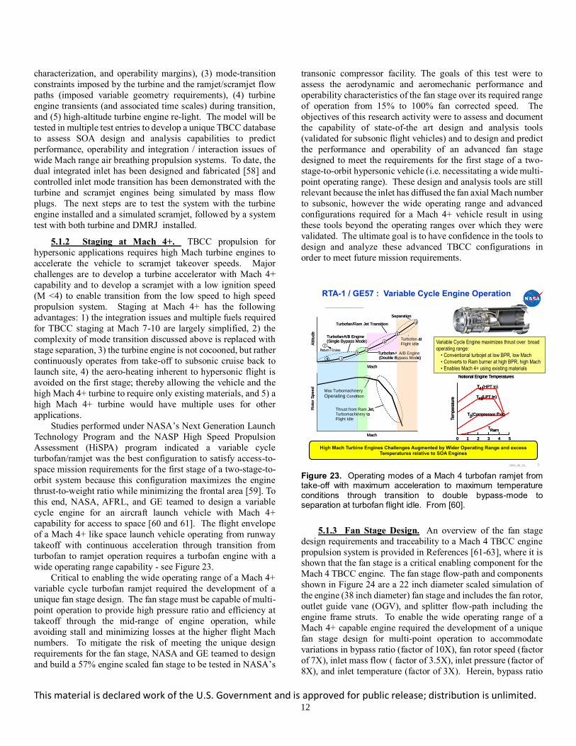
5.1.2 Staging at Mach 4+. TBCC propulsion for
hypersonic applications requires high Mach turbine engines to
accelerate the vehicle to scramjet takeover speeds. Major
challenges are to develop a turbine accelerator with Mach 4+
capability and to develop a scramjet with a low ignition speed
(M <4) to enable transition from the low speed to high speed
propulsion system. Staging at Mach 4+ has the following
advantages: 1) the integration issues and multiple fuels required
for TBCC staging at Mach 7-10 are largely simplified, 2) the
complexity of mode transition discussed above is replaced with
stage separation, 3) the turbine engine is not cocooned, but rather
continuously operates from take-off to subsonic cruise back to
launch site, 4) the aero-heating inherent to hypersonic flight is
avoided on the first stage; thereby allowing the vehicle and the
high Mach 4+ turbine to require only existing materials, and 5) a
high Mach 4+ turbine would have multiple uses for other
applications.
Studies performed under NASA’s Next Generation Launch
Technology Program and the NASP High Speed Propulsion
Assessment (HiSPA) program indicated a variable cycle
turbofan/ramjet was the best configuration to satisfy access-to-
space mission requirements for the first stage of a two-stage-to-
orbit system because this configuration maximizes the engine
thrust-to-weight ratio while minimizing the frontal area [59]. To
this end, NASA, AFRL, and GE teamed to design a variable
cycle engine for an aircraft launch vehicle with Mach 4+
capability for access to space [60 and 61]. The flight envelope
of a Mach 4+ like space launch vehicle operating from runway
takeoff with continuous acceleration through transition from
turbofan to ramjet operation requires a turbofan engine with a
wide operating range capability - see Figure 23.
Critical to enabling the wide operating range of a Mach 4+
variable cycle turbofan ramjet required the development of a
unique fan stage design. The fan stage must be capable of multi-
point operation to provide high pressure ratio and efficiency at
takeoff through the mid-range of engine operation, while
avoiding stall and minimizing losses at the higher flight Mach
numbers. To mitigate the risk of meeting the unique design
requirements for the fan stage, NASA and GE teamed to design
and build a 57% engine scaled fan stage to be tested in NASA’s
transonic compressor facility. The goals of this test were to
assess the aerodynamic and aeromechanic performance and
operability characteristics of the fan stage over its required range
of operation from 15% to 100% fan corrected speed. The
objectives of this research activity were to assess and document
the capability of state-of-the art design and analysis tools
(validated for subsonic flight vehicles) and to design and predict
the performance and operability of an advanced fan stage
designed to meet the requirements for the first stage of a two-
stage-to-orbit hypersonic vehicle (i.e. necessitating a wide multi-
point operating range). These design and analysis tools are still
relevant because the inlet has diffused the fan axial Mach number
to subsonic, however the wide operating range and advanced
configurations required for a Mach 4+ vehicle result in using
these tools beyond the operating ranges over which they were
validated. The ultimate goal is to have confidence in the tools to
design and analyze these advanced TBCC configurations in
order to meet future mission requirements.
Figure 23. Operating modes of a Mach 4 turbofan ramjet from take-off with maximum acceleration to maximum temperature conditions through transition to double bypass-mode to separation at turbofan flight idle. From [60].
5.1.3 Fan Stage Design. An overview of the fan stage
design requirements and traceability to a Mach 4 TBCC engine
propulsion system is provided in References [61-63], where it is shown that the fan stage is a critical enabling component for the
Mach 4 TBCC engine. The fan stage flow-path and components
shown in Figure 24 are a 22 inch diameter scaled simulation of
the engine (38 inch diameter) fan stage and includes the fan rotor,
outlet guide vane (OGV), and splitter flow-path including the
engine frame struts. To enable the wide operating range of a
Mach 4+ capable engine required the development of a unique
fan stage design for multi-point operation to accommodate
variations in bypass ratio (factor of 10X), fan rotor speed (factor
of 7X), inlet mass flow ( factor of 3.5X), inlet pressure (factor of
8X), and inlet temperature (factor of 3X). Herein, bypass ratio
2009_09_28_ 2
October 30 - November 1, 2007
RTA-1 / GE57 : Variable Cycle Engine Operation
Mach1 2 3 4 5
T41(HPT In)
0
Tem
pera
ture
Notional Engine Temperatures
T49(LPT In)
TRam
T3(Compressor Exit)
Mach1 2 3 4 5
T41(HPT In)
0
Tem
pera
ture
Notional Engine Temperatures
T49(LPT In)
TRam
T3(Compressor Exit)
Mach1 2 3 4 5
T41
0
Tem
pera
ture
Notional Engine Temperatures
T49(LPT In)
TRam
T3(Compressor Exit)
Variable Cycle Engine maximizes thrust over broad
operating range:
• Conventional turbojet at low BPR, low Mach
• Converts to Ram burner at high BPR, high Mach
• Enables Mach 4+ using existing materials
SeparationA
ltitude
Turbofan atFlight Idle
Turbofan/Ram Jet Transition
Turbofan-A/B Engine (Single Bypass Mode)
Turbofan-A/B Engine(Double Bypass Mode)
Mach
Roto
r S
peed
Mach
Thrust from Ram Jet, Turbomachinery toFlight Idle
Max Turbomachinery Operating Condition
SeparationA
ltitude
Turbofan atFlight Idle
Turbofan/Ram Jet Transition
Turbofan-A/B Engine (Single Bypass Mode)
Turbofan- A/B Engine(Double Bypass Mode)
Mach
Roto
r S
peed
Mach
Thrust from Ram Jet, Turbomachinery toFlight Idle
Max Turbomachinery
Operating Condition
6
1
23
4
5
8
7
Return / Cruise
X Alt. facility test points
High Mach Turbine Engines Challenges Augmented by Wider Operating Range and excess Temperatures relative to SOA Engines

This material is declared work of the U.S. Government and is approved for public release; distribution is unlimited. 13
is defined as the ratio of mass flow in the bypass duct to that in
the core duct. See Figure 24.
Figure 24. Fan stage components and flow path of the Mach 4+ turbofan ramjet from Figure 23. From [65].
These large variations of the inlet conditions and rotational
speed introduced the following aerodynamic technical
challenges to the fan stage design:
1. Stall free operation of the fan stage from 15%-110% rotor
design speed (corrected).
2. Minimize the pressure losses through the fan rotor and OGV
especially at the very high bypass ratios where the fan stage
is at or approaching windmill conditions.
3. Avoid choking and provide clean and stable flow in the
bypass and core ducts throughout the 10x range of bypass
ratio.
4. Deliver the required inlet conditions to the downstream
engine components (ramjet and core compressor), from
takeoff through transonic and to ramjet operation.
These technical challenges were augmented by the requirement
to maintain traceability to the reference TBCC vehicle which
resulted in 1) a fan stage design without inlet guide vanes;
thereby, making it more difficult to maintain performance and
operability over the wide operating range, and 2) a bypass duct
arrangement that must maintain a diameter consistent with scale-
up to the reference vehicle, yet not be so small as to incur large
pressure losses or potential flow choking resulting from high
Mach numbers in the duct. Overall fan stage performance and
operability therefore requires major consideration, as competing
goals at different operating points become major drivers in the
design. The details of the mechanical design and aeromechanic
test data are found in [62 and 63], respectively.
The fan stage was designed by GE following their standard
design practice, with close collaboration from NASA engineers
providing multistage CFD analysis in support of the design with
emphasis on operability and performance at off-design
conditions. The fan rotor was designed to produce a high
pressure ratio (2.5) at lower flight Mach numbers while
maintaining adequate stall margin (>10%) across a wide range
of operating conditions. In order to deliver the required
performance, an advanced technology, forward swept fan rotor
design [62-64], was employed. The fan stage design operating
line (as determined by GE’s cycle code to meet mission
requirements) is depicted by the black line connecting the black
circles in Figure 25. CFD simulations were used to update the
fan stage performance maps in the engine cycle deck. Single
blade row CFD analyses were run, using GE’s inhouse code,
along the operating line at 100%, 90%, 80%, 50%, 37%, 20%
and 15% of design speed, as well as near stall at 100% and 80%
speed. Multi-stage CFD analyses, utilizing NASA’s APNASA
code, were also conducted at select operating conditions (100%,
50%, and 37% of design speed. These simulations predicted that
the fan stage should be capable of matching the design intent
across the operating range. In order to ensure adequate stall
margin over the operating range, the fan stage test article
provided the flexibility to incorporate various casing treatments
over the fan rotor by installing a liner insert as depicted in Figure
24.
Figure 25. Mach 4+ Turbofan Ramjet engine Fan stage
operating map - design operating line indicated by black circles. From [65].
The fan stage was tested in the NASA W8 Single Stage
Compressor facility, which was modified to enable independent throttling of the bypass and core flow ducts to map the
compressor over the wide range of operating conditions.
Aerodynamic fan stage performance characteristics at 15%,
25%, 37%, 50%, 60%, 70%, 80%, 85%, 90%, 95%, and 100%
of rotor design speed, encompassing a bypass ratio swing from
0.7 to 7, were acquired. These experimental results of the fan
stage characteristics were acquired for three different fan rotor
casing configurations corresponding to 1) smooth wall at
nominal fan tip clearance, 2) circumferentially grooved casing at
nominal tip clearance, and 3) circumferentially grooved casing
with a more open clearance. The liner influenced the stage
performance and operability for fan speeds greater than 70%
speed, but no influence was measured below 70% speed where
% Corrected Fan Flow0 20 40 60 80 100
3.00
2.50
2.00
1.50
1.00
.90
.50
Fa
n P
res
su
re R
ati
o
• Windmill Region
PR < 1
• Design Fan PR = 2.45 for Base Map
- Single Stage
- No IGV
10% 20% 30% 40%50% 60%
70%80%
90%100 %Speed
Minimum Stall margin
or flutter margin range
Take-Off
Low bypass mode
BPR ~ 0.7
37% Speed Max
Bypass Ratio ~7)
Potential Fan OGV and
outer duct choking region
Maximum fan OGV
aero loading, ADPEngine Cycle Predicted / Intent
Single Blade Row CFD Analysis (TACOMA)
Multistage Analysis (APNASA)
Adiabatic
Efficiency
Contours
This material is declared work of the U.S. Government and is approved for public release; distribution is unlimited. 14
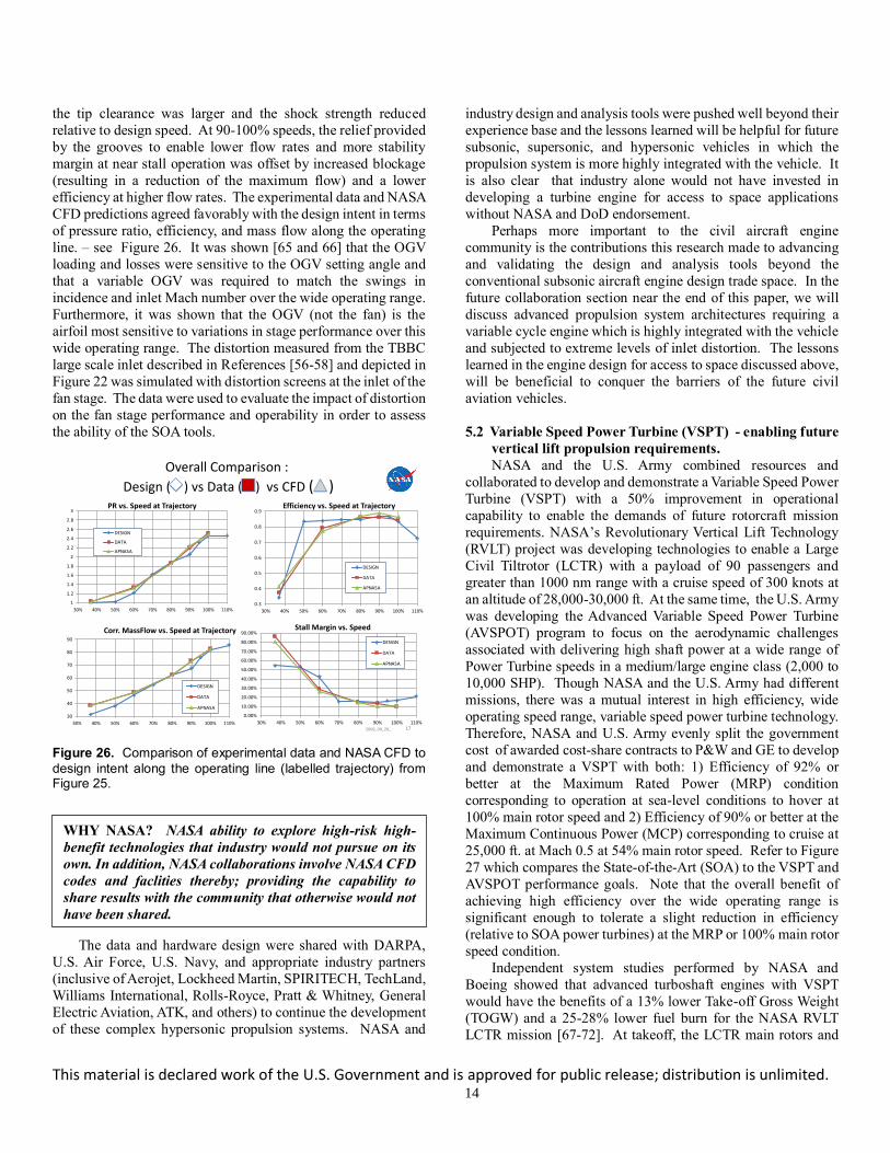
the tip clearance was larger and the shock strength reduced
relative to design speed. At 90-100% speeds, the relief provided
by the grooves to enable lower flow rates and more stability
margin at near stall operation was offset by increased blockage
(resulting in a reduction of the maximum flow) and a lower
efficiency at higher flow rates. The experimental data and NASA
CFD predictions agreed favorably with the design intent in terms
of pressure ratio, efficiency, and mass flow along the operating
line. – see Figure 26. It was shown [65 and 66] that the OGV
loading and losses were sensitive to the OGV setting angle and
that a variable OGV was required to match the swings in
incidence and inlet Mach number over the wide operating range.
Furthermore, it was shown that the OGV (not the fan) is the
airfoil most sensitive to variations in stage performance over this
wide operating range. The distortion measured from the TBBC
large scale inlet described in References [56-58] and depicted in
Figure 22 was simulated with distortion screens at the inlet of the
fan stage. The data were used to evaluate the impact of distortion
on the fan stage performance and operability in order to assess
the ability of the SOA tools.
Figure 26. Comparison of experimental data and NASA CFD to
design intent along the operating line (labelled trajectory) from Figure 25.
The data and hardware design were shared with DARPA,
U.S. Air Force, U.S. Navy, and appropriate industry partners
(inclusive of Aerojet, Lockheed Martin, SPIRITECH, TechLand,
Williams International, Rolls-Royce, Pratt & Whitney, General
Electric Aviation, ATK, and others) to continue the development
of these complex hypersonic propulsion systems. NASA and
industry design and analysis tools were pushed well beyond their
experience base and the lessons learned will be helpful for future
subsonic, supersonic, and hypersonic vehicles in which the
propulsion system is more highly integrated with the vehicle. It
is also clear that industry alone would not have invested in
developing a turbine engine for access to space applications
without NASA and DoD endorsement.
Perhaps more important to the civil aircraft engine
community is the contributions this research made to advancing
and validating the design and analysis tools beyond the
conventional subsonic aircraft engine design trade space. In the
future collaboration section near the end of this paper, we will
discuss advanced propulsion system architectures requiring a
variable cycle engine which is highly integrated with the vehicle
and subjected to extreme levels of inlet distortion. The lessons
learned in the engine design for access to space discussed above,
will be beneficial to conquer the barriers of the future civil
aviation vehicles.
5.2 Variable Speed Power Turbine (VSPT) - enabling future
vertical lift propulsion requirements.
NASA and the U.S. Army combined resources and
collaborated to develop and demonstrate a Variable Speed Power
Turbine (VSPT) with a 50% improvement in operational
capability to enable the demands of future rotorcraft mission
requirements. NASA’s Revolutionary Vertical Lift Technology
(RVLT) project was developing technologies to enable a Large
Civil Tiltrotor (LCTR) with a payload of 90 passengers and
greater than 1000 nm range with a cruise speed of 300 knots at
an altitude of 28,000-30,000 ft. At the same time, the U.S. Army
was developing the Advanced Variable Speed Power Turbine
(AVSPOT) program to focus on the aerodynamic challenges
associated with delivering high shaft power at a wide range of
Power Turbine speeds in a medium/large engine class (2,000 to
10,000 SHP). Though NASA and the U.S. Army had different
missions, there was a mutual interest in high efficiency, wide
operating speed range, variable speed power turbine technology.
Therefore, NASA and U.S. Army evenly split the government
cost of awarded cost-share contracts to P&W and GE to develop
and demonstrate a VSPT with both: 1) Efficiency of 92% or
better at the Maximum Rated Power (MRP) condition
corresponding to operation at sea-level conditions to hover at
100% main rotor speed and 2) Efficiency of 90% or better at the
Maximum Continuous Power (MCP) corresponding to cruise at
25,000 ft. at Mach 0.5 at 54% main rotor speed. Refer to Figure
27 which compares the State-of-the-Art (SOA) to the VSPT and
AVSPOT performance goals. Note that the overall benefit of
achieving high efficiency over the wide operating range is
significant enough to tolerate a slight reduction in efficiency
(relative to SOA power turbines) at the MRP or 100% main rotor
speed condition.
Independent system studies performed by NASA and
Boeing showed that advanced turboshaft engines with VSPT
would have the benefits of a 13% lower Take-off Gross Weight
(TOGW) and a 25-28% lower fuel burn for the NASA RVLT
LCTR mission [67-72]. At takeoff, the LCTR main rotors and
2009_09_28_ 17
0.3
0.4
0.5
0.6
0.7
0.8
0.9
30% 40% 50% 60% 70% 80% 90% 100% 110%
Efficiency vs. Speed at Trajectory
DESIGN
DATA
APNASA
1
1.2
1.4
1.6
1.8
2
2.2
2.4
2.6
2.8
3
30% 40% 50% 60% 70% 80% 90% 100% 110%
PR vs. Speed at Trajectory
DESIGN
DATA
APNASA
0.00%
10.00%
20.00%
30.00%
40.00%
50.00%
60.00%
70.00%
80.00%
90.00%
30% 40% 50% 60% 70% 80% 90% 100% 110%
Stall Margin vs. Speed
DESIGN
DATA
APNASA
30
40
50
60
70
80
90
30% 40% 50% 60% 70% 80% 90% 100% 110%
Corr. MassFlow vs. Speed at Trajectory
DESIGN
DATA
APNASA
Overall Comparison :
Design ( ) vs Data ( ) vs CFD ( )
WHY NASA? NASA ability to explore high-risk high-
benefit technologies that industry would not pursue on its
own. In addition, NASA collaborations involve NASA CFD
codes and faclities thereby; providing the capability to
share results with the community that otherwise would not
have been shared.

This material is declared work of the U.S. Government and is approved for public release; distribution is unlimited. 15
the VSPTs operate at 100% speed, while at cruise the rotors tilt
forward and the VSPTs are slowed to 54% speed to enable higher
efficiency. high speed forward flight cruise. The LCTR engine
requirements were established with the NASA engine
performance group [73]. The cruise and takeoff VSPT enthalpy
extraction levels differ by only 8 to 10%. As the shaft is slowed
from 100% to 54% of the takeoff speed, the turbine work factor
(Δht/Utip2) is increased by a factor of 3.4. The corrected flows
(or Mach numbers) do not change significantly, and therefore the
flow coefficient essentially doubles between the takeoff (100%)
and cruise (54%) operating conditions. The nearly constant
corrected flow rates and the 40% corrected speed change lead to
incidence angle variations of 40° to 60° in all turbine blade and
vane rows downstream of the first vane, including any required
exit guide vane row. The aerodynamic challenges include
attainment of high turbine efficiency with incidence variations in
all blade rows associated with the shaft speed change, combined
with operation at low Reynolds numbers with attendant
sensitivity to transitional flow. The loss levels in the transitional
flow fields of low-pressure turbines (LPTs) operating at cruise
altitudes (with Re < 100 k) are strongly affected by wake-induced
unsteadiness as well. The mechanical challenges are associated
with the required avoidance or management of responsive shaft,
blade, and casing modes at critical speeds within the operational
speed range of the VSPT shaft. More details on the VSPT
challenges are discussed in References [74-76].
Figure 27. Variable Speed Power Turbine (VSPT) performance goals relative to current technology. From [87].
NASA awarded VSPT study contracts to Rolls-Royce and
Williams International to define a notional VSPT. The contractor
reports can be found in References [77] and [78]. The Rolls-
Royce VSPT concept was selected and the third stage of their
VSPT was used to design a non-proprietary incidence tolerant
blade design which was tested in the NASA CW-22 facility and
in the University of North Dakota (UND) turbine cascade
facilities. NASA VSPT blade cascade testing at high and low
inlet turbulence levels over a large range of Mach numbers,
Reynolds numbers, and incidence provided a benchmark data
base to validate the ability of CFD analysis codes to predict the
VSPT losses over the entire flight operating envelope. A sample
of the test results are provided in Figures 28 and 29. Additional
details of the experiment(s) and their results are documented in
References [79-85]. NASA used these test results to validate the
ability of models to predict flow separation and laminar-to-
turbulent flow transition. The data at low and high inlet
turbulence provides a unique opportunity to develop LES
methods in a step-wise manner. The low inlet turbulence data
enables LES without the necessity to model the inlet turbulence
via a sub-grid model References [85 and 86]. These test results
were provided to P&W and GE to assist them with their VSPT
designs.
P&W and GE independently developed notional engines to
define the design requirements for their power turbines to meet
the NASA/Army performance requirements under the Army’s
Advanced Variable Speed Power Turbine (AVSPOT) program.
Based on their notional engine VSPT component test rigs were
designed, fabricated, and tested to demonstrate that their design
would meet the performance requirements. The nearly full-
scale, multi-stage VSPT component rigs were tested and met or
exceeded the efficiency goals of the design. These results were
especially satisfying because the goals were very aggressive
(Figure 1) and they were achieved without employing a variable
turbine geometry. CFD was integrally used in the VSPT design
process. Pratt & Whitney’s and GE’s post-test analysis of the
detailed rig data indicated that their CFD codes had accurately
predicted the radial distribution of the key flow field parameters,
the vane pressure distributions, and the overall performance over
the wide operating range. In addition, NASA independently
performed CFD analysis using TURBO [88] and the ADS Code
LEO [89] for the P&W VSPT design. As shown in Figure 30,
the NASA CFD predicted the overall performance of the VSPT
at 55% speed and 100% speed in reasonable agreement with the
P&W test results. Additional details of these results are provided
in reference [87].
Figure 28. VSPT Blade Loss Coefficient versus Incidence for various Reynolds and Mach numbers – Low Inlet Turbulence. From [87].
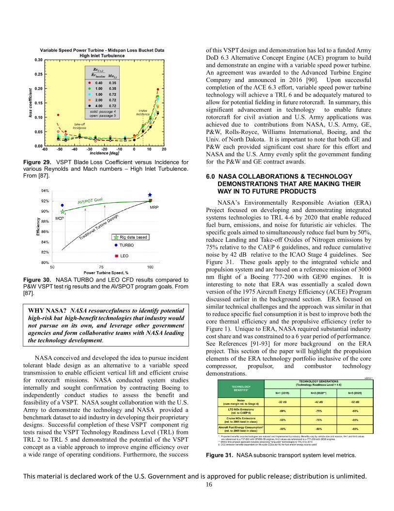
This material is declared work of the U.S. Government and is approved for public release; distribution is unlimited. 16
Figure 29. VSPT Blade Loss Coefficient versus Incidence for various Reynolds and Mach numbers – High Inlet Turbulence. From [87].
Figure 30. NASA TURBO and LEO CFD results compared to P&W VSPT test rig results and the AVSPOT program goals. From [87].
NASA conceived and developed the idea to pursue incident
tolerant blade design as an alternative to a variable speed
transmission to enable efficient vertical lift and efficient cruise
for rotorcraft missions. NASA conducted system studies
internally and sought confirmation by contracting Boeing to
independently conduct studies to assess the benefit and
feasibility of a VSPT. NASA sought collaboration with the U.S.
Army to demonstrate the technology and NASA provided a
benchmark dataset to aid industry in developing their proprietary
designs. Successful completion of these VSPT component rig
tests raised the VSPT Technology Readiness Level (TRL) from
TRL 2 to TRL 5 and demonstrated the potential of the VSPT
concept as a viable approach to improve engine efficiency over
a wide range of operating conditions. Furthermore, the success
of this VSPT design and demonstration has led to a funded Army
DoD 6.3 Alternative Concept Engine (ACE) program to build
and demonstrate an engine with a variable speed power turbine.
An agreement was awarded to the Advanced Turbine Engine
Company and announced in 2016 [90]. Upon successful
completion of the ACE 6.3 effort, variable speed power turbine
technology will achieve a TRL 6 and be adequately matured to
allow for potential fielding in future rotorcraft. In summary, this
significant advancement in technology to enable future
rotorcraft for civil aviation and U.S. Army applications was
achieved due to contributions from NASA, U.S. Army, GE,
P&W, Rolls-Royce, Williams International, Boeing, and the
Univ. of North Dakota. It is important to note that both GE and
P&W each provided significant cost share for this effort and
NASA and the U.S. Army evenly split the government funding
for the P&W and GE contract awards.
6.0 NASA COLLABORATIONS & TECHNOLOGY DEMONSTRATIONS THAT ARE MAKING THEIR WAY IN TO FUTURE PRODUCTS
NASA’s Environmentally Responsible Aviation (ERA)
Project focused on developing and demonstrating integrated
systems technologies to TRL 4-6 by 2020 that enable reduced
fuel burn, emissions, and noise for futuristic air vehicles. The
specific goals aimed to simultaneously reduce fuel burn by 50%,
reduce Landing and Take-off Oxides of Nitrogen emissions by
75% relative to the CAEP 6 guidelines, and reduce cumulative
noise by 42 dB relative to the ICAO Stage 4 guidelines. See
Figure 31. These goals apply to the integrated vehicle and
propulsion system and are based on a reference mission of 3000
nm flight of a Boeing 777-200 with GE90 engines. It is
interesting to note that ERA was essentially a scaled down
version of the 1975 Aircraft Energy Efficiency (ACEE) Program
discussed earlier in the background section. ERA focused on
similar technical challenges and the approach was similar in that
to reduce specific fuel consumption it is best to improve both the
core thermal efficiency and the propulsive efficiency (refer to
Figure 1). Unique to ERA, NASA required substantial industry
cost share and was constrained to a 6 year period of performance.
See References [91-93] for more background on the ERA
project. This section of the paper will highlight the propulsion
elements of the ERA technology portfolio inclusive of the core
compressor, propulsor, and combustor technology
demonstrations.
Figure 31. NASA subsonic transport system level metrics.
WHY NASA? NASA resourcefulness to identify potential
high-risk but high-benefit technologies that industry would
not pursue on its own, and leverage other government
agencies and form collaborative teams with NASA leading
the technology development.

This material is declared work of the U.S. Government and is approved for public release; distribution is unlimited. 17
6.1 NASA ERA Core Compressor Technology Development.
The ERA core compressor activity was a collaboration
between NASA and GE Aviation. To achieve the system goals,
the goal of the ERA highly loaded compressor activity was to
increase efficiency and to increase pressure rise by 30% relative
to the ERA baseline engine (GE90 engine on the 777-200) in
order to achieve a 2.5% reduction in engine specific fuel
consumption. Two test and analysis campaigns explored the
design space to improve the compressor Overall Pressure Ratio
(OPR) and optimize the blade loading and efficiency without
negatively impacting weight, length, diameter, or operability.
The first test campaign (NASA ERA Phase 1) investigated the
front two stages of a legacy high-pressure ratio six-stage core
compressor to determine what limits blade loading. The second
test campaign (NASA ERA Phase 2) focused on two builds of
the front stages of a new compressor design. A pictorial view of
the design space explored is found in Figure 32. The dashed line
represents compressor trade space state of the art (SOA) for
blade loading (represented as the change in enthalpy divided by
the square of the rotor tip rotational speed) and efficiency. As
shown, the higher blade loading, the more difficult it is to achieve
high efficiency. Any compressor with a design point above the
dashed line would represent a design that was better than the
SOA.
Figure 32. Compressor design space for ERA Phase 1 and Phase 2 relative to the state-of-the-art best current practices as indicated by the dashed line, representing the change in enthalpy dHave divided by the square of the rotor tip rotational speed. From [93].
In ERA Phase 1, a legacy high-OPR compressor design that
fell short of the efficiency design goals was investigated. The
high losses were attributed to the front two stages of this highly
loaded six-stage compressor design. The front two stages are
transonic across the span, so their performance is very sensitive
to variations in the effective flow area. Those area variations
can affect the location and strength of the passage shocks and
further impact flow separations and/or low momentum and loss
regions due to the shock and/or blade row interactions. Figure
33 shows the results of an unsteady CFD analysis by Gorrell [94]
of the front two stages of the compressor and it highlights the
entropy (loss) regions for the transonic compressor flow field.
NASA tested the first stage in isolation followed by the two-stage
configuration in the NASA W7 multi-stage compressor facility
to evaluate the performance and losses in each stage. For both
1- and 2-stage configurations, detailed data were taken at 97%
design speed, acquiring data from leading-edge (LE)
instrumentation, wall statics, over-the-rotor high frequency
response Kulite pressure sensors, and traversing probes. The
results indicated that Stage 2 was choking at a mass flow rate
that prevented Stage 1 from reaching its peak efficiency point,
leading to a stage mismatch issue. The mismatch was thought to
be due to losses in the first stage that were not predicted by
design tools. Assessment of the Stator 1 LE measurements in
both test configurations revealed that the level of performance at
this location was unaffected by the presence of the second stage.
Therefore, the major source of unexplained loss resulted from
the first stage of the compressor. For additional details and
discussion of the CFD analysis and experimental test results refer
to Celestina, et al. [95], Prahst et al [96] and Lurie et al [97].
Figure 33. Shock and wake loss regions due to unsteady blade row Interactions (for the IGV + Rotor 1 + Stator 1 + Rotor 2) along the midspan stream surface of a highly loaded compressor identified by Entropy contours from Gorrell et al, 2005 [94].
ERA Phase 2 brought forward a completely new core compressor design strategy and leveraged lessons learned from
the Phase 1 compressor design. The Phase 2 compressor was
designed for increased efficiency and blade loading, relative to
best current design as shown Figure 32. However, based on
learnings from Phase 1, the blade-loading levels were increased
relative to best current design but not to the higher levels of blade
loading that were attempted in the Phase 1 design discussed
previously. For ERA Phase 2, NASA tested the first three stages
of a high-efficiency, high-OPR core compressor design in the
same NASA facility as the Phase 1 testing. The Phase 2
compressor test campaign consisted of a Build 1 test and a Build
2 test in which the primary difference was that Build 2 was
designed to achieve higher compressor blade loading (pressure

This material is declared work of the U.S. Government and is approved for public release; distribution is unlimited. 18
rise per stage) at the same efficiency levels of Build 1, as shown
in Figure 32. The higher blade loading of Build 2 provided an
overall system benefit because it allowed for the compressor
bleed locations to be moved further upstream, thereby reducing
the compressor work required to provide the bleed flow.
Extensive CFD simulations that have been conducted are not
only in agreement with each other but are also in agreement with
the design intent. Build 2 testing indicated the compressor met
its design intent. These technology demonstrations contributed
to GE’s advanced core compressor development.
6.2 NASA ERA Propulsor Technology Development Effort.
The NASA ERA performance goals for the propulsor were
a 9% Reduction in TSFC and a 15 EPNdB cumulative noise
reduction relative to the baseline engine. Advanced ultra-high-
bypass ratio propulsors are attractive to provide increased
propulsive efficiency and reduced fan and jet noise to meet the
ERA goals at the expense of increased nacelle weight and drag
for ducted propulsors. Unducted open rotor systems optimize
propulsive efficiency with ultimate bypass ratio and low fan
pressure ratio but lack nacelle liners thereby resulting in less
noise suppression than ducted systems. To address these
challenges the approach was to study the trade space between
fuel burn and noise reduction by assessing ducted and unducted
propulsor systems.
6.2.1 NASA ERA Ducted Ultra High Bypass (UHB)
Propulsor Technology Development Efforts. Aircraft engine
noise and fuel burn reduction are directly correlated to fan size,
fan pressure ratio, and fan bypass ratio. As the fan size increases,
there is a corresponding drop in the fan pressure ratio and an
increase in fan Bypass Ratio (BPR). At some point, as the fan
size continues to increase, an optimum is reached between fan
size and nacelle weight and drag. The larger, heavier nacelle
produces more drag during flight, and overcomes the advantages
of a larger fan. The addition of a gear to the fan drive system
allows the low tip speed, low Fan Pressure Ratio (FPR) fan to be
coupled to a smaller, more efficient, high speed core. This shifts
the minimum fuel burn FPR to a lower value for geared turbofan
as shown in Figure 34. However, note that the fan diameter is
also increasing to produce an equivalent amount of thrust. For
higher thrust class engines, the nacelle will become prohibitively
large with high drag unless reduced length nacelles are also
implemented [98]. These configuration changes are beneficial
for fuel burn but potentially detrimental for acoustics. Therefore,
to meet the ERA goals for fuel burn reduction and noise
reduction, NASA collaborated with Pratt & Whitney and the
Federal Aviation Administration to develop and demonstrate an
Integrated UHB fan with a low weight nacelle system and
advanced noise reduction technologies.
For engines with large diameter fans and reduced length
nacelles the internal surface area for acoustics liners is reduced
and the effectiveness of the liners is also lowered due to the less
optimal Length to Diameter (L/D) ratio of the bypass duct. To
increase the acoustic treatment area in the propulsor the NASA
ERA program developed two advanced liner concepts; over the
rotor (OTR) and soft vanes (SV). The OTR concept is an
acoustically designed casing treatment which is located over the
rotor tip region. The details are not releasable as a patent is in
process. The design intent is to absorb pressure fluctuations at
the source before the sound can propagate to the far field. The
SV concept uses cylindrical, folded passages in the fan exit guide
vanes to absorb pressure fluctuations at their source. Both
concepts are used to effectively increase the acoustically treated
area within the propulsor. The OTR/SV concepts were tested in
a legacy 1.5 pressure ratio fan, both in a rotor only configuration
to analyze any performance impact [99] and in a flight nacelle
configuration to measure the acoustic characteristics. The
nacelle configuration is shown schematically in Figure 35. The
rotor-alone measurements showed a minimal and acceptable loss
in efficiency due to the OTR treatment. The acoustic results from
the flight nacelle showed a noise reduction for the SV concept of
1.5 dB but no noise reduction for the OTR concept.
Manufacturing difficulties for the OTR concept and acoustic
design limitations for the rotor tip flow field conditions are the
likely causes of the inconclusive acoustic results for the concept.
Figure 34. Fuel burn and noise characteristics of advanced turbofans and geared engines (from P&W, 2015 [93].
Figure 35. Over the rotor (OTR) and Soft Vane (SV) acoustic concepts in the legacy 1.5 Fan Pressure Ratio (FPR) fan model. From, [93].

This material is declared work of the U.S. Government and is approved for public release; distribution is unlimited. 19
The final wind tunnel test of the series, known as Rig 2, used
a scale model version of the FAA CLEEN engine. The wind
tunnel model contained many of the features of an engine such
as a drooped inlet, pylon/bifurcation in the bypass duct, classed
exit guide vanes and a non-axisymmetric bypass duct. A
comprehensive data set was acquired to assess performance,
operability, and acoustics; thereby validating the SOA design and
analysis tools. A primary objective of the experiment was to
compare model scale acoustic results to those of the upcoming
full-scale ground engine test. NASA nor FAA would have been
capable with their funding alone to complete this comprehensive
series of test programs.
6.2.2 NASA ERA Unducted Propulsor Technology
Development Efforts. Propulsion systems incorporating open
rotors have the potential for game-changing reductions in fuel
burn because of their low fan pressure ratio and thus increased
propulsive efficiency. To meet the ERA goals for fuel burn
reduction and noise reduction, NASA collaborated with General
Electric Aviation and the Federal Aviation Administration to
explore the design space for lower noise while maintaining the
high propulsive efficiency from a counter-rotating open-rotor
system. Candidate technologies for lower noise were
investigated as well as installation effects such as pylon and
fuselage integration. Advances in computational fluid dynamics
over the last 20 years enable three-dimensional (3D) tailoring of
blade shapes to minimize noise while still maintaining
efficiency. These modeling advances increase the possibility of
meeting both noise and efficiency goals simultaneously for the
new generation of open-rotor designs.
During the test campaign six different blade sets or unique
combinations of fore and aft blades were evaluated for their
aerodynamic performance and acoustic characteristics. One of
the blade sets, the Historical Baseline blade set, is representative
of 1990s blade design. Aerodynamic and acoustic measurements
of the Historical Baseline blade set were used as a benchmark
dataset to improve modeling and simulation capabilities for open
rotors. The other five blade sets represent modern designs that
incorporate various 3D design features and other strategies to
reduce the acoustic signature but maintain performance. The
open-rotor test campaign is documented in References [100 and
101], and the following paragraphs provide a brief synopsis of
the activity.
The open-rotor test program consisted of three phases: (1)
takeoff and approach aerodynamics and acoustics, (2)
diagnostics, and (3) cruise performance. For Phases 1 and 2 the
Open Rotor Propulsion Rig (ORPR) was installed in the 9- by
15-Foot Low-Speed Wind Tunnel (9X15 LSWT) at GRC. The
ORPR was completely refurbished for the current test entry and
also underwent significant upgrades such as a new digital
telemetry system for rotor force and strain gage monitoring. For
the third phase of testing the rig was installed in the 8- by 6-Foot
Supersonic Wind Tunnel (8X6 SWT) for cruise performance
testing. NASA acquired a substantial amount of aerodynamic
and acoustic data on a variety of blade geometries for an isolated
configuration during the Phase 1 testing. Figure 36 [90]
compares the fuel burn and noise levels of the GE36 (1980’s
open rotor) and turbofan engine to a modern open-rotor design.
It is clear from Figure 36 that the modern open-rotor designs
provide significant improvements in both fuel burn and noise
relative to the 1980’s GE36 UDF design; thereby making the
open rotor a viable propulsor concept for the next generation of
fuel-efficient aircraft.
Figure 36. Modern open rotor designs provide greater than 25% reduction in fuel burn and about 8 EPNdB noise margin to International Civil Aviation Organization Chapter 4 standard (ICAO, 2008). From [92].
6.2.3 NASA Evaluates Propulsor SFC versus Noise
Trade Space. In order to perform a direct comparison of an
unducted open-rotor system to a high-BPR ducted propulsor,
NASA leveraged the research reported above and designed a
common aircraft platform to compare the tradeoff between fuel
burn and noise reduction [102]. The NASA notional aircraft
design was a modern 162-passenger airplane with rear fuselage-
mounted engines and with a cruising Mach number of 0.78 at
35,000 ft and a mission range of 3250 nautical miles. A
comparison of the fuel burn and noise for the open-rotor and
ducted high-bypass propulsors are shown in Figure 37. The
aircraft with the open-rotor propulsor provided an additional 9%
reduction in fuel burn despite the increased weight of the engine
and at the expense of an increase of 7 dB cum in noise relative
to the ducted propulsor for this notional aircraft size and mission.
6.3 NASA ERA Advanced Combustor Technology
Development Effort.
The NASA ERA performance goal for the combustor was a
75% reduction in LTO NOx relative to the CAEP 6 standard.
NASA ERA collaborated with General Electric (GE) Aviation
and Pratt & Whitney (P&W) in a cost share agreement to develop
the new lean burn concepts and demonstrate these concepts in a

This material is declared work of the U.S. Government and is approved for public release; distribution is unlimited. 20
sector rig test that simulates the pressures and temperatures of a
relevant high OPR (>50) engine environment. The NASA Glenn
Research Center (GRC) Advanced Subsonic Combustor Rig
(ASCR) facility was upgraded to provide combustor entrance
conditions up to a pressure of 900 psia and temperature up to
1300F to simulate an OPR 50 engine in order to perform the
combustor sector rig testing. These sector test results are
presented in reference [92].
Figure 37. Comparison of advanced turbofan and open rotor on common aircraft platform (From Hendricks, E. S., J. J. Berton, W. J. Haller, M. T. Tong, and M. D. Guynn. 2013. From [102].
GE Aviation designed and tested advanced lean burn
combustor concepts, which extended from the Twin Annular
Premixing Swirler (TAPS) developed under GE and NASA
sponsored Advanced Subsonic Technology (AST) and Ultra
Efficient Engine Technology (UEET) programs. More recently,
the TAPS combustor was further developed for application in the
new GEnx-1B and GEnx-2B engines that power the Boeing 787
and 747-8 wide-body aircraft, respectively. The TAPS design
consisted of independently controlled, swirl stabilized, annular
flames for low power (pilot) and high power (main) operation.
The central pilot flame provided good low power operability and
low CO and HC emissions. The main flame is concentric with
the pilot flame and was designed to produce low NOx emissions
during high power operation. The combustion system
incorporated advanced liner materials that benefitted both
durability and emissions by decreasing cooling air requirements
and enabling a higher fraction of combustion air in the main
mixer for lower NOx emissions. Several advanced TAPS
injector concepts were designed and tested in a flame tube
configuration to evaluate emissions, combustion dynamics, and
auto ignition margin up to full operating conditions. Based on
testing and analysis results an injector design was selected and
was incorporated into an advanced 5-cup sector rig at NASA’s
ASCR facility. The ASCR facility provides the capability to
obtain data over the entire flight envelop including high power
operation for the inlet conditions required to calculate the ICAO
LTO NOx emissions level for engines with an overall pressure
ratio of 50:1. The GE sector test results [92] indicated that the
GE combustor concept had the potential to meet the ERA goals.
Pratt & Whitney (P&W) concepts included lean-staged
multi-point designs, radially staged swirlers, rich-quench-lean
(RQL) combustors, and axially staged combustors. The
simplicity, operability, durability, and excellent emissions of the
RQL family of combustors have led to the continued use of the
concept in P&W engines. The most recent P&W combustor
TALON X, was developed with support from NASA under the
UEET program, and has been selected for the P&W Geared
Turbofan engine on upcoming Airbus, Bombardier and
Mitsubishi aircraft. In this effort, P&W and the United
Technology Research Center (UTRC) are investigating multiple
injection points and have used modern design and analysis tools
to improve the mixing. Initial testing of the concepts was
conducted at (UTRC) in an idealized Single Nozzle Rig. Results
at 7% and 30% power settings for various injector configurations
and fuel air ratios demonstrated [92] that all the concepts could
have emissions results below the goals set by NASA. A few of
the concepts performed very well with NOx emissions levels
substantially lower than the NASA goals as well as excellent
levels of efficiency. Based on additional testing and analysis an
injector concept design was selected and was developed into an
advanced 3-cup sector rig. The sector rig was tested at NASA’s
ASCR facility to measure performance, operability and
emissions at test conditions required to calculate the ICAO LTO
NOx emissions level. The P&W sector test results [92] indicated
that the P&W combustor concept had the potential to meet the
ERA goals.
The 75% LTO NOx reduction goal was considered to be a
significant challenge for partial pre-mix combustor
configurations at the start of ERA Phase 1. ERA pursued partial
pre-mix concepts from both P&W and GE. In addition, as risk
mitigation, NASA studied lean direct injection (LDI) concepts
from three injector manufacturers in case the partial pre-mix
systems showed unresolvable autoignition issues at the higher
combustor pressures and temperatures of high OPR engines.
Active control strategies were also studied to mitigate any
stability issues that may arise for the lean burn concepts. Finally,
alternative fuel blends up to 100% were studied as a possible
replacement for Jet-A to improve NOx performance. Details of
the ERA Phase 1 testing are described in reference [92]. At the
conclusion of Phase 1 testing, the partial pre-mix concepts from
both P&W and GE had shown the potential to meet the LTO NOx
goal, without LDI, active combustion control, or alternative
fuels. The P&W concept was chosen for continued technology
maturation in ERA Phase 2.
P&W’s lean-lean concept, called the Axial Stage Combustor
(ASC) is shown schematically in Figure 38. The ASC concept
uses a pilot injector at the front of the combustor for low power
conditions. Additional main injectors are used in addition to the
pilot injector for high power conditions. The fuel-air mixture is
kept lean through the entire axial length of the combustor. The
lean burn configuration is necessary to maintain low NOx
production at the N+2 cycle conditions as defined in Figure 31.
The LTO NOx performance of ASC concepts was validated in
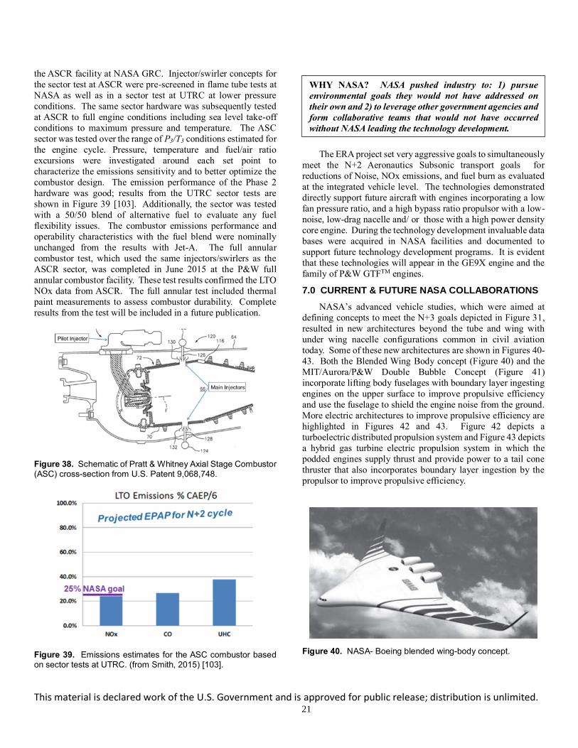
This material is declared work of the U.S. Government and is approved for public release; distribution is unlimited. 21
the ASCR facility at NASA GRC. Injector/swirler concepts for
the sector test at ASCR were pre-screened in flame tube tests at
NASA as well as in a sector test at UTRC at lower pressure
conditions. The same sector hardware was subsequently tested
at ASCR to full engine conditions including sea level take-off
conditions to maximum pressure and temperature. The ASC
sector was tested over the range of P3/T3 conditions estimated for
the engine cycle. Pressure, temperature and fuel/air ratio
excursions were investigated around each set point to
characterize the emissions sensitivity and to better optimize the
combustor design. The emission performance of the Phase 2
hardware was good; results from the UTRC sector tests are
shown in Figure 39 [103]. Additionally, the sector was tested
with a 50/50 blend of alternative fuel to evaluate any fuel
flexibility issues. The combustor emissions performance and
operability characteristics with the fuel blend were nominally
unchanged from the results with Jet-A. The full annular
combustor test, which used the same injectors/swirlers as the
ASCR sector, was completed in June 2015 at the P&W full
annular combustor facility. These test results confirmed the LTO
NOx data from ASCR. The full annular test included thermal
paint measurements to assess combustor durability. Complete
results from the test will be included in a future publication.
Figure 38. Schematic of Pratt & Whitney Axial Stage Combustor (ASC) cross-section from U.S. Patent 9,068,748.
Figure 39. Emissions estimates for the ASC combustor based on sector tests at UTRC. (from Smith, 2015) [103].
The ERA project set very aggressive goals to simultaneously
meet the N+2 Aeronautics Subsonic transport goals for
reductions of Noise, NOx emissions, and fuel burn as evaluated
at the integrated vehicle level. The technologies demonstrated
directly support future aircraft with engines incorporating a low
fan pressure ratio, and a high bypass ratio propulsor with a low-
noise, low-drag nacelle and/ or those with a high power density
core engine. During the technology development invaluable data
bases were acquired in NASA facilities and documented to
support future technology development programs. It is evident
that these technologies will appear in the GE9X engine and the
family of P&W GTFTM engines.
7.0 CURRENT & FUTURE NASA COLLABORATIONS
NASA’s advanced vehicle studies, which were aimed at
defining concepts to meet the N+3 goals depicted in Figure 31,
resulted in new architectures beyond the tube and wing with
under wing nacelle configurations common in civil aviation
today. Some of these new architectures are shown in Figures 40-
43. Both the Blended Wing Body concept (Figure 40) and the
MIT/Aurora/P&W Double Bubble Concept (Figure 41)
incorporate lifting body fuselages with boundary layer ingesting
engines on the upper surface to improve propulsive efficiency
and use the fuselage to shield the engine noise from the ground.
More electric architectures to improve propulsive efficiency are
highlighted in Figures 42 and 43. Figure 42 depicts a
turboelectric distributed propulsion system and Figure 43 depicts
a hybrid gas turbine electric propulsion system in which the
podded engines supply thrust and provide power to a tail cone
thruster that also incorporates boundary layer ingestion by the
propulsor to improve propulsive efficiency.
Figure 40. NASA- Boeing blended wing-body concept.
WHY NASA? NASA pushed industry to: 1) pursue
environmental goals they would not have addressed on
their own and 2) to leverage other government agencies and
form collaborative teams that would not have occurred
without NASA leading the technology development.

This material is declared work of the U.S. Government and is approved for public release; distribution is unlimited. 22
Figure 41. MIT, Aurora, and P&W double bubble aircraft concept – electric or motor driven.
Figure 42. NASA turboelectric distributed propulsion concept – note electric.
Figure 43. NASA Single-aisle Turboelectric Aircraft with an Aft Boundary-Layer propulsor (STARC- ABL) hybrid electric concept.
Embedded engines with boundary layer ingestion offer an
additional fuel burn benefit of up to 5% to 10% because of their
reacceleration of fluid that had been slowed by the viscous drag
of the vehicle. This technology benefits the propulsive efficiency
of the vehicle as described in Figure 44 by reducing the jetting
velocity compared to that of a podded engine and by reducing
the vehicle wake deficit. The potential benefit depends upon the
percentage of the boundary layer from the vehicle ingested into
the engines, so some concepts attempt to capture a larger
percentage of this boundary layer by using distributed propulsors
across the upper surface of the vehicle. Blended-wing-body
vehicles offer an attractive method to leverage boundary-layer-
ingesting (BLI) engines because of their larger surface area,
which results in a larger boundary layer and in more flexibility
of engine mounting on the upper surface of the lifting body.
Figure 44. Propulsion benefits of boundary layer ingestion (BLI) due to the fact that propulsive efficiency approaches 100% as the jet exit velocity (Ujet) is reduced to the flight speed of the vehicle.
One of the challenges for BLI engines, however, is the
potential loss in fan efficiency and degradation of life due to the
inlet distortion and resulting unsteady forces imposed on the
rotating fan. NASA collaborated with UTRC to investigate
integrated inlet and fan designs that mitigate the negative impact
of the inlet distortion on fan efficiency and operability. The goal
was to demonstrate an embedded integrated inlet and distortion-
tolerant fan system that provides the identified aircraft benefits
by achieving less than a 2% loss in fan efficiency while
maintaining ample stability margin. The study used an existing
NASA Research Announcement (NRA) sponsored blended-
wing-body design such as that depicted in Figure 40, to define
the design constraints for the inlet boundary layer and the
requirements for a relevant embedded engine configuration.
NASA partnered with UTRC, Pratt & Whitney, and Virginia
Polytechnic and State University (Virginia Tech) through the
NRA to exploit the optimal design space and to design and build
an integrated inlet and fan embedded system. A sampling of the
relevant publications supporting this activity including the
simulated aircraft boundary layer, the embedded inlet and
distortion tolerant fan design, and the aeromechanics analysis is
found in References [104-110].
Figure 45. Boundary layer ingesting (BLI) fan test rig installed in
NASA Glenn 8- by 6-Foot Supersonic Wind Tunnel (86 SWT). (a) Bars upstream of fan are used to thicken boundary layer, and downstream bleed plates are used to customize boundary layer upstream of fan inlet. (b) close-up of the integrated inlet and fan installation in the 8x6 SWT.
NASA recently completed the testing of a distortion-tolerant
fan with a relevant boundary layer inflow field in the 8- by 6-
Foot Supersonic Wind Tunnel at GRC. The arrangement of this
embedded propulsor experiment is shown in Figure 45. A false
floor was inserted in the tunnel to mount the inlet/fan hardware.

This material is declared work of the U.S. Government and is approved for public release; distribution is unlimited. 23
Note that the rods located far upstream of the embedded fan inlet
provide a thick inlet boundary layer. Downstream of the rods
and upstream of the inlet, the false floor contains a porous section
to provide bleed control to adjust the incoming fan/inlet
boundary layer to simulate that of a hybrid wing-body vehicle
such as the one shown in Figure 41. The first phase of testing
was completed in summer of 2017. Much learning was achieved
in the initial test and a summary of the results are provided in
reference [111]. However, it was evident from these results that
the following tool improvements are required: 1) integrated inlet
fan design tools, 2) integrated vehicle inlet design and analysis
tools, and 3) aeromechanics and fluid structural interaction
analysis and assessment tools.
More electric and Hybrid Gas turbine Electric Propulsion
(HGEP) vehicles open a vast design trade space by simply
allowing a decoupling of the propulsor and power generator.
This decoupling opens the possibility for highly distributed
propulsors that can be arranged to optimize the airframe drag and
control services; thereby providing propulsive efficiency
improvements as well as reductions in noise and emissions.
These improvements come at a cost of additional airport and
vehicle infrastructure and the complexity that the vehicle,
powertrain, and controls be highly integrated as well as designed
concurrently. In addition, powered electronics and batteries
require additional safety considerations and produce significant
amounts of heat. Unlike the gas turbine engine where the waste
heat is ejected out the exhaust nozzle to the atmosphere, the
electronics heat is low quality heat and will require additional
thermal management systems to transport the heat from the
source. An additional challenge is that the specific technical
barriers for these advanced vehicle architectures is highly
configuration specific. However, due to the potential benefit of
these HGEP vehicles, it is necessary to investigate these
technical issues.
It is evident that HGEP configurations are much less mature
and require significant improvements in tools to estimate the
weight, volume, power density, efficiency and reliability of the
electrical components to perform basic system studies. To this
end, NASA has released a series of NRA’s focused on
developing high power density motors/generators, AC/DC
power converters, and integrated controls and power
management. Furthermore, NASA has invested in the
development of the NEAT (NASA Electric Aircraft Testbed)
facility to enable development and testing of electrical
components of large-scale electric aircraft powertrains. The
facility has a reconfigurable architecture that industry, academia,
and government can use to evaluate the efficiency, power
distribution and controls of the electrical components to further
mature HGEP vehicles. Investments to understand the impact
of power extraction on the turbine engine and how to leverage
the electronic components to optimize the HGEP system has
been severely lacking. A dedicated approach to understand the
impact of power extraction on the design and operability of the
gas turbine engine is required. In addition, integrated power and
thermal management of the gas turbine with the electrical
components and vehicle will be a key technology that needs to
be further developed to make these systems realizable for large
aircraft.
For high-speed flight, NASA Supersonics activities are
focused on minimizing the sonic boom and working with the
FAA to determine acceptable noise levels for supersonic flight
over land. When the FAA requirements are determined, the next
major challenge will be to maximize engine efficiency at cruise
and address the landing and take-off noise near the airport. To
satisfy both these competing requirements, a variable cycle
engine with high bypass at takeoff (to address noise
requirements) and low bypass ratio at cruise (to reduce SFC) will
likely be required. Furthermore, emissions at high altitude cruise
could become a major barrier.
In summary, it is clear that the propulsion system will be
highly integrated with the vehicle inclusive of controls, power,
and thermal management. In addition, the gas turbine engine
will remain the prime source of power generation for the
foreseeable future for larger aircraft (> 75 passengers).
Therefore, it is essential to continue to develop and demonstrate
high power density and highly efficient core engines with
adaptive features to better integrate with the varying load
demands of the electrical components. Furthermore, additive
manufacturing, more distributed propulsion via hybrid gas
turbine electric propulsion systems, and new multidisciplinary
design tools inclusive of machine learning will open the design
space and may generate vehicles and concepts significantly
different than those we are familiar with today. An additional
challenge is that the specific technical barriers for these
advanced vehicle architectures is highly configuration specific.
Therefore, it is necessary for the gas turbine community to
identify a set of technology barriers that are common to many of
these future architectures and identify common model problems
that the community can work together to enhance and validate
their respective design and analysis tools. Subsequently, tool
assessment exercises and system demonstrations are suggested
to anchor the capability of these enhanced tools.
8.0 SUMMARY & CONCLUDING REMARKS
The history of the NASA Glenn Research Center (1940 to
present) coincides with an era of dramatic reductions in aircraft
fuel burn, emissions, and noise, largely attributed to
improvements in the engine. NASA GRC has contributed
greatly to this improvement through full engine testing; engine
component testing and development; analytical tool and model
development; research investigating fundamental flow physics;
and computational fluid dynamics validation; all in partnership
with the aircraft engine community. NASA has a distinctive role
in advancing gas turbine engine technology because the
government has the expertise, facilities, and flexibility to pursue
impactful research in depth and the ability to share detailed pre-
competitive research results. Furthermore, NASA is uniquely
positioned to work with industry, academia, and other
government agencies on proprietary and export-controlled
technologies; thereby enabling NASA to understand the needs of
civilian and military aviation and to form collaborations that
provide technologies that are beneficial to the entire gas turbine

This material is declared work of the U.S. Government and is approved for public release; distribution is unlimited. 24
community. This paper reviewed NASA’s role and contributions
to turbine engine development, specific to both 1) NASA’s role
in conducting experiments to understand flow physics and
provide relevant benchmark validation experiments for (CFD)
code development, validation, and assessment, and 2) the impact
of technologies resulting from NASA collaborations with
industry, academia and other government agencies. In addition
to the technical contributions and impact to the gas turbine
community, the paper highlighted the following intangible
attributes that NASA brings to the team developing the
technology:
• NASA’s flexibility to explore beyond the original scope
to maximize learning and provide reliable benchmark
data sets for the gas turbine community.
• NASA’s flexibility to create and leverage collaborations
to continue technology development from theory to
engine component demonstration.
• NASA’s ability to explore high-risk, high-benefit
technologies that industry would not pursue on its own.
• NASA’s collaborations involving NASA‘s CFD codes
and facilities thereby; providing the capability to share
results with the community that otherwise would not
have been shared.
• NASA’s resourcefulness to leverage other government
agencies and form collaborative teams that would not
occur without NASA leading the technology
development.
• NASA’s collaborations set aggressive performance and
environmental goals that would not be addressed
without NASA involvement.
Are NASA technology investments still needed to enable
future turbine engine-based propulsion systems? Given the
potential for advanced architectures employing BLI or hybrid
electric propulsion will NASA be needed to help develop the
design and analysis tools, databases, and technology
demonstration programs to meet the challenges? This of course
is for the industry and the gas turbine engine community to
decide. To this end, GE and P&W provided an overview slide
depicting their perspective of NASA’s impact on their products
of the past and where they seek NASA participation in the future.
GE provided a roadmap for their next generation future
‘Additive Analytical Affordable Engine’ - see Figure 46. GE
shows the NASA and government technology collaboration
projects and/or programs in the upper curve and the GE products
on the lower curve. It is interesting to note from Figure 46 that
GE reports NASA’s $200M investment in the E3 project enabled
$3 Billion dollars of industry investment resulting in $35 Billion
dollars of sales and the generation of 15,000 jobs over a 30-year
period of impact. Similarly, P&W has provided a technology
roadmap showing how NASA and P&W collaborative
development and test campaigns have impacted the development
of the geared turbofan engine and next generation UHB
propulsor– see Figure 47. Per Figure 47, P&W GTFTM provided
a 16% reduction in fuel consumption, 50% reduction in regulated
emissions, 75% reduction in noise footprint and more than 9000
new engine orders from 80 different customers. From Figures
46 and 47, it is apparent NASA has clearly played a key role in
advancing technologies for turbine engine development. In
conclusion, NASA is well-positioned and eager to continue our
legacy to form collaborations that provide technologies that are
beneficial to the entire gas turbine community.
Figure 46. GE perspective of NASA Impact on their product development due to NASA Partnerships and technology demonstrations. Chart provided courtesy of GE: Copyright GE.
Figure 47. P&W perspective of NASA Impact on their product development due to NASA Partnerships and technology demonstrations. Chart provided courtesy of P&W: Copyright P&W.
NOMENCLATURE
ACE Alternative Concept Engine
ACEE Aircraft Energy Efficiency (program)
AFRL Air Force Research Laboratory
ARMD Aeronautics Research Mission Directorate
ASC Axial Stage Combustor
ASCR Advanced Subsonic Combustion Rig
AVSPOT Advanced Variable Speed Power Turbine (Program)
BLI Boundary Layer Ingesting
UDF
ADVENT
HEETE
AATE
QCSEE
E3
80’s
00’s
70’s
90’s
TECH56
FATE
OPEN ROTOR
10’s
AETDBuilding on our shared legacy … learning from GE’s experience with the world’s largest fleet
NASA – GE … a legacy of partnership on demos & products
20’s +
GE9X
LEAP
GEnx
GE90
CF6
CFM56
demos
products
Passport
Additive AnalyticalAffordable Engine
NASA $200M investment enabled …~ $3B industry investment~ $35B sales~ 15,000 jobs+ 30 years of impact
Copyright GE
NASA-PW TECHNOLOGY COLLABORATION & IMPACT
UTC PROPRIETARY - This page does not contain any export controlled technical data.
1988-1991 1992-19951996-1999
2000-2003
2004-2007
2008-2011
2012-2015
2016-2019
2020+
Future Generation GTF
1st Generation GTF
ADP X-Engine
Flight Weight Gears
ATFI X-Engine
Gear Test Rigs
Flight Test Validation
Demo X-Engine
Customer Flight Demonstration
Fan Rig Tests
Engine Ground Tests
Flight Test Validation
BLI2DTF Rig Test
DISRUPTIVEBLI2DTF2 Rig
Tests
ACS Combustor
GEN1 GTF Impact Summary:
16% reduction in fuel consumption
50% reduction in regulated emissions
75% reduction in noise footprint
9000+ orders and 80+ customers
Approved By Pratt & Whitney For Public Release
Photo Credit:
NASAPhoto Credit:
NASA
All Photos are PW credit unless otherwise noted

This material is declared work of the U.S. Government and is approved for public release; distribution is unlimited. 25
BPR Bypass Ratio
CAEP Committee on Aircraft Environmental Protection
CFD Computation Fluid Dynamics
CLEEN Continuous Lower Emissions and Noise
DMRJ Dual Mode Ramjet
EPA Environmental Protection Agency
ERA Environmentally Responsible Aviation (project)
ERB Engine Research Building
E3 Energy Efficient Engine (project)
FAA Federal Aviation Administration
FPR Fan Pressure Ratio
GE General Electric
GRC Glenn Research Center
GTFTM Geared Turbofan
H or h Enthalpy
HGEP Hybrid Gas turbine / Electric Propulsion
ICAO International Committee on Aircraft Operations
IGV Inlet Guide Vane
LPT Low Pressure Turbine
LCTR Large Civil Tiltrotor
LDI Lean Direct Injection
LDV Laser Doppler velocimetry
LE Leading Edge
LTO Landing and Take-Off
OPR Overall Pressure Ratio
M Mach Number
Mrel Relative Mach Number
MCP Maximum Continuous Power
MIT Massachusetts Institute of Technology
MRP Maximum Rated Power
NACA National Aeronautics
NASA National Advisory Committee for Aeronautics
NOx oxides of nitrogen
NRA NASA Research Announcement
OGV Outlet Guide Vane
OPEC Organization of Petroleum-Exporting Countries
OTR Over the Rotor
P4 Total pressure far downstream of the blade
Pref Reference pressure (standard day inlet).
PS Pressure Surface
P3 Combustor entrance pressure
P&W Pratt & Whitney
Recx Reynolds number based on axial chord
RVLT Revolutionary Vertical Lift Technology (project)
SOA State-of the Art
SHP Shaft Horse Power
SS Suction Surface
SV Soft Vane
TAPS Twin Annular Premixing Swirler
T3 Combustor entrance temperature
TBCC Turbine Based Combined Cycle
TRL Technology Readiness Level
TSFC Thrust Specific Fuel Consumption
Tip Rotational speed of the wheel at the mean tip radius
UDF Unducted Fan
UEET Ultra Efficient Engine Technology
UTRC United Technologies Research Center
VSPT Variable Speed Power Turbine
3X The min to max variation of the parameter varies by
a factor of 3 times, similar for 7X, 10X, etc.
stall Difference in the stalling mass flow (baseline minus
with tip injection) normalized by the baseline
stalling flow; where the baseline is without tip
injection.
CUS Difference in customer bleed flow)
CDP Difference in compressor discharge bleed flow
ht Change in enthalpy across the rotor
REFERENCES
[1] Epstein, A. H. 2014. Aeropropulsion for commercial
aviation in the twenty-first century and research directions
needed, AIAA Journal 52(5):901-911,
doi:10.2514/1.J052713.)
[2] Bullock, R. O., and Johnsen, I. A. 1965. Aerodynamic
design of axial flow compressors. NASA SP–36.
[3] Glassman, Arthur J., ed., 1972, “Turbine Design and
Application”, NASA SP-290.
[4] Bowles, M. D. 2010. The “Apollo” of aeronautics: NASA's
aircraft energy efficiency program, 1973–1987. NASA e-
book,
http://www.nasa.gov/connect/ebooks/aero_apollo_detail.h
tml (accessed August 31, 2016).
[5] Ciepluch, C. C., Davis, D. Y., and Gray, D. E. 1987. Results
of NASA's energy efficient engine program. J. Propul.
Power 3:560‒568.
[6] Davis, D. Y., and Stearns, E. M. 1985. Energy efficient
engine: flight propulsion system final design and analysis.
NASA CR–168219.
[7] Strazisar, A. J. 1985. Investigation of flow phenomena in a
transonic fan using laser anemometry. J. Eng. Power—T.
ASME 107:427-436.
[8] Hathaway, M. D., Gertz, J. B., Epstein, A. H., and Strazisar,
A. J. 1986. Rotor wake characteristics of a transonic axial
flow fan. AIAA J. 24:1802–1810.
[9] Wood, J. R., Strazisar, A. J., and Simonyi, P. S. 1987. Shock
structure measured in a transonic fan using laser
anemometry. AGARD–CP–401.
[10] Strazisar, A. J., Wood, J. R., Hathaway, M. D., and Suder,
K. L. 1989. Laser anemometer measurements in a transonic
axial-flow fan rotor. NASA TP–2879.
[11] Suder, K. L., Okiishi, T. H., Hathaway, M. D., Strazisar, A.
J., and Adamczyk, J. J. 1987. Measurements of the
unsteady flow field within the stator row of a transonic
axial-flow fan: Part I—measurement and analysis
technique. ASME Paper 87–GT–226.
[12] Hathaway, M. D., Okiishi, T. H., Suder, K. L., Strazisar, A.
J., and Adamczyk, J. J. 1987. Measurements of the
unsteady flow field within the stator row of a transonic
axial-flow fan: Part II— results and discussion. ASME
Paper 87–GT–227.

This material is declared work of the U.S. Government and is approved for public release; distribution is unlimited. 26
[13] Suder, K.L., 1996. "Experimental Investigation of the
Flow Field in a Transonic Axial Flow Compressor with
Respect to the Development of Blockage and Loss." Ph.D.
Dissertation Case Western Reserve University, also NASA
TM107310, August 1996.
[14] Suder, K.L., and Celestina, M.L., 1996. "Tip Clearance
Vortex / Shock Interactions in a Highly Loaded Transonic
Compressor Rotor." J. Turbomach, Vol. 118, no. 2, 1996,
pp. 218-229.
[15] Suder, K.L., 1998. "Blockage Development in A
Transonic, Axial Flow Compressor", J. Turbomach., Vol.
120, No. 3, 1998, pp.465-476.
[16] Reid, L., and Moore, R. D. 1978. Design and overall
performance of four highly loaded, high speed inlet stages
for an advanced, high-pressure-ratio core compressor.
NASA TP–1337.
[17] Dunham, J. 1998. AGARD WG26 report - summary of 13
different simulations of Rotor 37 AGARD Advisory Report
AR-355, May 1998 CFD Validation for Propulsion System
Components. Also summarized in ASME 98-GT-050.
[18] Denton, J., 1996. “Lessons Learned from Rotor 37.
Presented at the Third International Symposium on
Experimental and Computational
Aerothermodynamics of Internal Flows (ICIASF), Beijing,
China, September 1-6, 1996.
[19] Dalbert and Wiss. 1995 “Numerical Transonic Flowfield
Predictions for NASA Compressor Rotor 37,” ASME 95-
GT-326.
[20] Arima, T.A., Sonoda, T., and Masatoshi, S. A. 1997.
Numerical Investigation of Transonic Axial Compressor
Rotor Flow Using a Low Reynolds Number k-epsilon
Turbulence Model (R37 and R67) ASME 97-GT-082.
[21] Arima, T., Masatoshi, S, and Yamaguchi, Y. 1998. The
Flow Field in the Tip Clearance Region of an Axial
Compressor Rotor.
[22] Arima, T., Sonoda, T., Shirotori, M., and Yamaguchi, Y.
1998. Computation of Subsonic and Transonic Compressor
Rotor Flow Taking Account of Reynolds Stress Anisotropy.
ASME 98-GT-423.
[23] Calvert, W, J., A Synthesis of NASA Compressor Rotor 37
Using a 3D CFD Code Proceedings of "Verification of
Design Methods by Test and Analysis," Royal Aeronautical
Society, www.raes.org.uk.
[24] Chima, R. 1996. A K-omega Turbulence Model for Quasi-
Three-Dimensional Turbomachinery Flows, NASA
TM10705, AIAA Reno Meeting, 1996.
[25] Chima, R. 1998. Calculation of Tip Clearance Effects in a
Transonic Compressor Rotor, ASME J of Turbo, Vol. 120,
p. 131-140, 1998.
[26] Shabbir, A. 1996. Assessment of Three Turbulence Models
in a Compressor Rotor 96-GT-198.
[27] Hah and Loellbach. 1997. Development of Hub Corner
Stall and Its Influence on the Performance of Axial
Compressor Blade Rows, ASME 97-GT-042 (to be
published in ASME J. of Turbomachinery).
[28] Shabbir, A.,1997. The Effect of Hub Leakage Flow on Two
High Speed Axial Compressor Rotors, ASME 97-GT-346
(to be published in ASME J. of Turbomachinery).
[29] Arnone, A. 1997. Grid Dependency Study for the NASA
Rotor 37 Compressor Blade ASME 97-GT-384.
[30] Calvert, J. 1997. Evaluation of a 3D Viscous Code for
Turbomachinery Flows, ASME 97-GT-078.
[31] Van Zante, D. E., Adamczyk, J. J., Strazisar, A. J., and
Okiishi, T. H. 2002. Wake recovery performance benefit in
a high-speed axial compressor. J. Turbomach. 124:275–
284.
[32] Hathaway, M. D., Chriss, R. M., Wood, J. R., and Strazisar,
A. J. 1993. Experimental and computational investigation
of the NASA low-speed centrifugal compressor flow field.
J. Turbomach., 115:527–542.
[33] Skoch, G. J., and Moore, R. D. 1987. Performance of two
10-lb/sec centrifugal compressors with different blade and
shroud thicknesses operating over a range of Reynolds
numbers. NASA TM–100115 (AVSCOM–TR–87–C–21
and AIAA–87–1745).
[34] Skoch, G. J., Prahst, P. S., Wernet, M. P., Wood, J. R., and
Strazisar, A. J. 1997. Laser anemometer measurements of
the flow field in a 4:1 pressure ratio centrifugal impeller.
NASA TM–107541 (ARL–TR–1448 and ASME Paper 97–
GT–342).
[35] Giel, P. W., Van Fossen, G. J., Boyle, R. J., Thurman, D.
R., and Civinskas, K. C. 1999. Blade heat transfer
measurements and predictions in a transonic turbine
cascade. NASA/TM—1999-209296.
[36] Giel, P. W., D. R. Thurman, G. J. VanFossen, S. A.
Hippensteele, and R. J. Boyle, 1998. "Endwall Heat
Transfer Measurements in a Transonic Turbine Cascade,"
J. Turbomach., Vol. 120, No. 2, pp. 305-313, April 1998.
[37] Durbin, P. A., and Pettersson Reif, B. A. 2001. Statistical
Theory and Modeling for Turbulent Flows. New York, NY:
John Wiley & Sons.
[38] Adamczyk, J. J. 1984. Model equation for simulating flows
in multistage turbomachinery. NASA TM‒86869.
[39] Celestina, M. L., and Mulac, R. A. 2009. Assessment of
stage 35 With APNASA. AIAA 2009–1057.
[40] Herrick, G. P., Hathaway, M. D., and Chen, J. 2009.
Unsteady full annulus simulations of a transonic axial
compressor stage. AIAA 2009–1059.
[41] Ameri, A. A. 2009. NASA ROTOR 37 CFD CODE
validation: Glenn-HT code. AIAA 2009‒1060.
[42] Hah, C. 2009. Large eddy simulation of transonic flow
field in NASA Rotor 37. AIAA 2009–1061.
[43] Chima, R. V. 2009. SWIFT code assessment for two similar
transonic compressors. AIAA 2009–1058.
[44] Suder, K. L., Chima, R. J., Strazisar, A. J., and Roberts, W.
B. 1994. "The Effects of Adding Roughness and Thickness
to a Transonic / Supersonic Axial Compressor Rotor." J.
Turbomach., Vol. 117, no. 4, 1994, pp. 491-505.
[45] Roberts, W. B., 1995, “Advanced Turbofan Blade
Refurbishment Technique,” J. Turbomach., Tech. Brief,
Vol. 117, pp 666-667.

This material is declared work of the U.S. Government and is approved for public release; distribution is unlimited. 27
[46] Roberts, W. B., Armin, A., Kassaseya, G., Suder, K. L.,
Thorp, S. A., and Strazisar, A. J., 2002. “The Effect of
Variable Chord Length on Transonic Axial Rotor
Performance,”, J. Turbomach., Vol. 124, pp. 351-356, July,
2002.
[47] Roberts, W. B., Prahst, P. S., Thorp, S., Strazisar, A.J. 2005.
“The Effect of Ultrapolish on a Transonic Axial Rotor,”
ASME GT2005-69132, proceedings of the ASME Turbo
Expo 2005, June 6-9, 2005, Reno, Nevada.
[48] Berdanier, R. A., and Key, N. L., 2015. “An Experimental
Investigation of the Flow Physics Associated with End
Wall Losses and Large Rotor Tip Clearances as Found in
the Rear Stages of a High Pressure Compressor,
NASA/CR-2015-218868.
[49] Volino, R. J., 2011. Experimental and Computational
Investigation of Unsteady Endwall and Tip Gap Flows in
Gas Turbine Passages, Final Report for NASA Interagency
Agreement NNC11IA11I. June 2011-Septtember 2016,
delivered Jan 25, 2017.
[50] Katz, J. 2017. “High Resolution Measurements of the
Effects of Tip Geometry on Flow Structure and Turbulence
in the Tip Region of a Rotor Blade. Final Report for NASA
Grant/ Cooperative Agreement Number: NNX11AI21A for
the period of June 6, 2011-July 31, 2016. Final Report
Delivered February 2017.
[51] Weigl, H. J., Paduano, J. D., Frechette, L. G., Epstein, A.
H., Greitzer, E. M., Bright, M. M., and Strazisar, A. J. 1998.
“Active Stabilization of Rotating Stall and Surge in a
Transonic Single Stage Axial Compressor,” J. Turbomach.,
Vol. 120, 1998, No. 4, pp. 625-636.
[52] Spakovszky, Z. S., Weigl, H. J., Paduano, J. D., Van
Schalkwyk, C. M., Suder, K. L., Bright, M., and Strazisar,
A. J. 1998. “Rotating Stall Control in a High-Speed Stage
with Inlet Distortion, Part I - Radial Distortion”, J.
Turbomach., Vol. 121, 1999, pp. 510-516.
[53] Spakovszky, Z. S., Weigl, H. J., Paduano, J. D., Van
Schalkwyk, C. M., Suder, K. L., Bright, M., and Strazisar,
A. J. 1999. “Rotating Stall Control in a High-Speed Stage
with Inlet Distortion, Part II - Circumferential Distortion”,
J. Turbomach., Vol. 121, 1999, pp. 517-524.
[54] Suder, K. L., Hathaway, M. D., Thorp, S. A., Strazisar, A.
J., and Bright, M. M. 2001. “Compressor Stability
Enhancement Using Discrete Tip Injection”, J.
Turbomach., Vol. 123, No. 1, pp. 14-23, January, 2001.
[55] Strazisar, A. J., Bright, M. M., Thorp, S. A., Culley, D.,
Suder, K. L, and Prahst, S. 2004. “Compressor Stall
Control Through Endwall Recirculation”, ASME GT2004-
54295 in Proceedings of the ASME Turbo EXPO 2004
Power for Land, Sea, and Air, June 14-17, 2004 selected
for ASME Journal.
[56] Suder, Kenneth. L., and Thomas, Scott, R. 2009. “An
Overview of the NASA Hypersonic Project's Combined
Cycle Engine Mode Transition Research Experiment,”
Paper 0664 at the JANNAF (Joint Army, Navy, NASA, Air
Force) 43rd CS/31st APS/25th PSHS Joint Meeting; La
Jolla, CA Dec 7-11,2009.
[57] Auslender, Aaron, Suder, Kenneth. L., and Thomas, Scott,
R. 2009. “An Overview of the NASA FAP Hypersonics
Project Airbreathing Propulsion Research” AIAA Paper
185450 published and presented at the AIAA International
Space Planes and Hypersonic Systems Conference;
Bremen, Germany October, 2009.
[58] Sanders, B. W.; and Weir, L. J. 2008. “Aerodynamic
Design of a Dual-Flow Mach 7 Hypersonic Inlet System
for a Turbine-Based Combined-Cycle Hypersonic
Propulsion System,” NASA-CR-2008-215214, May 2008.
[59] Bilardo V.J., Curran F.M., Lovell N.T., and Maggio G.,
2003, “Benefits of Airbreathing Launch Systems for
Access to Space” AIAA 2003-5265, 39th Joint Propulsion
Conference
[60] Shafer D.G., McNelis N., 2003, “Development of a Ground
Based Mach 4+ Revolutionary Turbine Accelerator
Technology Demonstrator (RTATD) for Access to Space”
ISOABE 2003.
[61] “RTA Propulsion System Data Requirements/Boeing
TSTO Study from NASA Glenn”, RASER Contract NAS3-
01135, 2002.
[62] Mielke, M., 2009 “RTA / GE57 Subscale Fan Rig, Final
Report – Mechanical Design” NASA CR-2010-215814.
[63] Mielke, M., Clark, D., and Wood, P. 2009 “RTA / GE57
Subscale Fan Rig, Final Report – Aerodynamic Test
Results “, NASA CR-2009-215816.
[64] Suder, K.L, Adamczyk, J.J., Wood, P., Zenon, R., Mielke,
M., Powell, B., LaChapelle, D. 2005. “Design and Analysis
of a Mach 4 Capable Fan Stage for the RTA Turbine Based
Combined Cycle Propulsion System, Proceedings for the
JANNAF 40th Combustion Science and 28th Air Breathing
Propulsion Meeting June 13-17, 2005 Charleston, SC.
[65] Suder, K.L., Prahst, S. Thorp, S.A. 2010. “Results of an
advanced Fan Stage Operating over a Wide Range of Speed
& Bypass Ratio – Part I: Fan Stage design and
Experimental Results”, ASME GT2010-22825 In
Proceedings of the ASME Turbo EXPO 2010, June 14-19,
2010.
[66] Celestina, M.L., Suder, K.L., Kulkarni, S. 2010. “Results
of an advanced Fan Stage Operating over a Wide Range of
Speed & Bypass Ratio – Part II: CFD and Experimental
Results”, ASME GT2010-23386 In Proceedings of the
ASME Turbo EXPO 2010 June 14-19, 2010.
[67] Snyder, C. A., and Acree, C. W. 2012. “Preliminary
Assessment of Variable Speed Power Turbine Technology
on Civil Tiltrotor Size and Performance,” AHS 68th
Annual Forum, Fort Worth, TX, May 2012.
[68] Snyder, C. A. 2014. “Exploring advanced technology gas
turbine engine design and performance for the Large Civil
Tiltrotor (LCTR)”, 50th AIAA/ASME/SAE/ASEE Joint
Propulsion Conference, Cleveland, OH, July 28-30, 2014.
[69] Acree, C. W. and Snyder, C. A. 2012. “Influence of
Alternative Engine Concepts on LCTR2 Sizing and
Mission Profile,” AHS Future Vertical Lift Aircraft Design
Conference, San Francisco, CA, January 2012.
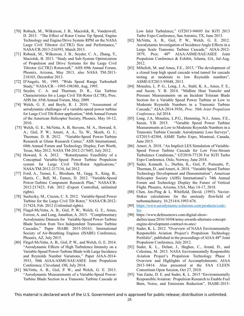
This material is declared work of the U.S. Government and is approved for public release; distribution is unlimited. 28
[70] Robuck, M., Wilkerson, J. B., Maciolek, R., Vonderwell,
D. 2013. “The Effect of Rotor Cruise Tip Speed, Engine
Technology and Engine/Drive System RPM on the NASA
Large Civil Tiltrotor (LCTR2) Size and Performance,”
NASA/CR-2013-216593, March 2013.
[71] Robuck, M., Wilkerson, J. B., Snyder, C. A., Zhang, Y.,
Maciolek, B. 2013. “Study and Sub-System Optimization
of Propulsion and Drive Systems for the Large Civil
Tiltrotor (LCTR2) Rotorcraft,” AHS 69th Annual Forum,
Phoenix, Arizona, May 2013, also NASA TM-2013-
218103, December 2013.
[72] D′Angelo, M., 1995. “Wide Speed Range Turboshaft
Study,” NASA/CR—1995-198380, Aug, 1995.
[73] Snyder, C. A. and Thurman, D. R., Gas Turbine
Characteristics for a Large Civil Tilt-Rotor (LCTR), Proc.
AHS Int. 65th Annual Forum, May, 2009.
[74] Welch, G. E. and Boyle, R. J. 2010. “Assessment of
aerodynamic challenges of a variable-speed power turbine
for Large Civil Tilt-Rotor application,” 66th Annual Forum
of the American Helicopter Society, Phoenix, May 10-12,
2010. [75] Welch, G. E., McVetta, A. B, Stevens, M. A., Howard, S.
A.; Giel, P. W.; Ameri, A. A., To, W., Skoch, G. J.;
Thurman, D. R. 2012. “Variable-Speed Power-Turbine
Research at Glenn Research Center,” AHS International,
68th Annual Forum and Technology Display, Fort Worth,
Texas, May 2012, NASA TM-2012-217605, July 2012.
[76] Howard, S. A. 2012. “Rotordynamic Feasibility of a
Conceptual Variable-Speed Power Turbine Propulsion
system for Large Civil Tilt-Rotor Applications,”
NASA/TM-2012-217134, Jul 2012.
[77] Ford, A., Turner, E., Bloxham, M., Gegg. S., King, B.,
Harris, C., Bell, M., Eames, D. 2012. “Variable-Speed
Power-Turbine Component Research Plan,” NASA/CR-
2012-217423, Feb. 2012 (Export Controlled, unlimited
rights).
[78] Suchezky, M., Cruzen, C. S. 2012. Variable-Speed Power
Turbine for the Large Civil Tilt Rotor,” NASA/CR-2012-
217424, Feb. 2012 (Unlimited rights).
[79] Flegel-McVetta, A. B., Giel, P. W., Welch, G. E., Ames,
Forrest, A. and Long, Jonathon, A. 2015. “Complimentary
Aerodynamic Datasets for Variable-Speed Power-Turbine
Blade Section from Two Independent Transonic Turbine
Cascades,” Paper ISABE 2015-20163, International
Society of Air-Breathing Engines (ISABE) Conference,
Phoenix, AZ, July 2015.
[80] Flegel-McVetta, A. B., Giel, P. W., and Welch, G. E. 2014.
“Aerodynamic Effects of High Turbulence Intensity on a
Variable-Speed Power-Turbine Blade with Large Incidence
and Reynolds Number Variations,” Paper AIAA-2014-
3933, 50th AIAA/ASME/SAE/ASEE Joint Propulsion
Conference, Cleveland, OH, July 2014.
[81] McVetta, A. B., Giel, P. W., and Welch, G. E. 2013.
“Aerodynamic Measurements of a Variable-Speed Power-
Turbine Blade Section in a Transonic Turbine Cascade at
Low Inlet Turbulence,” GT2013-94695 for IGTI 2013
Turbo Expo Conference, San Antonio, TX, June 2013.
[82] McVetta, A. B., Giel, P. W., Welch, G. E. 2012.
Aerodynamic Investigation of Incidence Angle Effects in a
Large Scale Transonic Turbine Cascade,” AIAA-2012-
3879, Proc. 48th AIAA/ASME/SAE/ASEE Joint
Propulsion Conference & Exhibit, Atlanta, GA, Jul-Aug.
2012.
[83] Mihelish, M. and Ames, F.E., 2013, “The development of
a closed loop high speed cascade wind tunnel for cascade
testing at moderate to low Reynolds numbers”,
ASME/GT2013-95048, 2013.
[84] Moualeu, L. P. G., Long, J. A., Stahl, K. A., Ames, F. E.,
and Suzen, Y. B. 2014. “Midline Heat Transfer and
Pressure Measurements on an Incident Tolerant Blade
Section for a Variable Speed Power Turbine at Low to
Moderate Reynolds Numbers in a Transonic Turbine
Cascade,” AIAA-2014-3936, Proc. 50th Joint Propulsion
Conference, Jul 2014.
[85] Long, J.A, Moualeu, L.P.G., Hemming, N.J., Ames, F.E.,
Suzen, Y.B. 2015. “Variable Speed Power Turbine
Measurements at Low to Moderate Reynolds Numbers in a
Transonic Turbine Cascade: Aerodynamic Loss Surveys”,
GT2015-42504, ASME Turbo Expo, Montreal, Canada,
June 2015.
[86] Ameri, A. 2018. “An Implicit LES Simulation of Variable-
Speed Power Turbine Cascade for Low Free-Stream
Turbulence Conditions,” GT2018-77120 For IGTI Turbo
Expo Conference, Oslo, Norway, June 2018.
[87] Suder, Kenneth. L., Durbin, K., Giel, P., Poinsatte, P.,
Thurman, D., and Ameri, A. 2018. “Variable Speed Turbine
Technology Development and Demonstration”, American
Helicopter Society (AHS) International’s 74th Annual
Forum and Technology Display the Future of Vertical
Flight. Phoenix, Arizona, USA, May 14-17, 2018.
[88] Chen, Jen-Ping & L. Whitfield, David. (1993). Navier-
Stokes calculations for the unsteady flowfield of
turbomachinery. 10.2514/6.1993-676.
[89] https://www.aerodynamic-solutions.com/products/code-
leo
[90] https://www.defensenews.com/digital-show-
dailies/ausa/2016/10/04/army-awards-alternate-concept-
engine-development-contract-to-atec/
[91] Suder, K. L. 2012. "Overview of NASA Environmentally
Responsible Aviation Project’s Propulsion Technology
Portfolio”, published in the proceedings of AIAA 48th Joint
Propulsion Conference, July 2012.
[92] Suder, K. L., Delaat, J., Hughes, C., Arend, D., and
Celestina, M. 2013. NASA Environmentally Responsible
Aviation Project’s Propulsion Technology Phase I
Overview and Highlights of Accomplishments. AIAA
2013–0414. Also presented at the FAA CLEEN
Consortium Open Session, Oct 27, 2010.
[93] Van Zante, D. E. and Suder, K. L. 2015 “Environmentally
Responsible Aviation: Propulsion Research to Enable Fuel
Burn, Noise, and Emissions Reduction”, ISABE-2015-

This material is declared work of the U.S. Government and is approved for public release; distribution is unlimited. 29
20209, 22nd International Symposium on Air Breathing
Engines, Phoenix, Arizona, Oct.25–30, 2015.
[94] Gorrell, Steve, Van de Wall, Alan, Tsung, Fu-Lin, 2005,
“Application of Time –Accurate CFD in Order to Account
for Blade-Row Interactions and Distortion Transfer in the
Design of High Performance Military Fans and
Compressors,” IEEE Computer Society Users Group
Conference, Paper 0-7695-2496-6/05.
[95] Celestina, M. L., Fabian, J. C., and Kulkarni, S. 2012.
NASA environmentally responsible aviation high overall
pressure ratio compressor research—pre-test CFD. AIAA
2012–4040.
[96] Prahst, P. S., Kulkarni, S., and Sohn. K. H. 2015.
Experimental results of the first two stages of an advanced
transonic core compressor under isolated and multi-stage
conditions. ASME Paper GT2015–42727.
[97] Lurie, David and Breeze-Stringfellow, Andrew, 2015.
“Evaluation of Experimental Data from a Highly Loaded
Transonic Compressor Stage to Determine Loss Sources,”,
ASME GT2015-42526, proceedings of the ASME Turbo
Expo 2015, June 15-19, 2015, Montreal, Canada.
[98] Peters, Andreas, Spakovszky, Zoltan S., Lord, Wesley K.
and Rose, Becky, 2014. “Ultra-Short Nacelles for Low Fan
Pressure Ratio Propulsors,” ASME GT2014-26369, June
16-20, 2014, Dusseldorf, Germany.
[99] Bozak, Richard F., Hughes, Christopher E., and Buckley,
James, 2013. “The aerodynamic performance of an over-
the-rotor liner with circumferential grooves on a high
bypass ratio turbofan rotor,” GT2013-95114, ASME
Turbo Expo 2013, San Antonio, TX, June 3-7, 2013.
[100] Van Zante, D. E. 2013. The NASA Environmentally
Responsible Aviation Project/General Electric Open Rotor
Test Campaign. AIAA 2013–0414.
[101] Van Zante, D. E., F. Collier, A. Orton, S. Arif Khalid, J. P.
Wojno, and T. H. Wood. 2014. Progress in open rotor
propulsors: the FAA/GE/NASA open rotor test campaign.
Aeronaut. J. 118:1181–1213.
[102] Hendricks, E. S., J. J. Berton, W. J. Haller, M. T. Tong, and
M. D. Guynn. 2013. Updated assessments of an open rotor
airplane using advanced blade designs. AIAA 2013–3628.
[103] Smith, Lance L. 2015. “N+2 and N+3 Low Emissions
Combustor Development,” presented during the AIAA
Science and Technology Forum, Kissimmee, FL, 7
January 2015.
[104] Arend, D. J., G. Tillman, and W. F. O’Brien. 2012.
Generation after next propulsor research: robust design
for embedded engine systems. AIAA 2012–4041.
[105] Florea, R. V., C. Matalanis, L. W. Hardin, M. Stucky, and
A. Shabbir. 2012. Parametric analysis and design for
embedded engine inlets. AIAA Paper 2012–3994.
[106] Bakhle, M. A., T. S. R. Reddy, G. P. Herrick, A. Shabbir,
and R. V. Florea. 2012. Aeromechanics analysis of a
boundary layer ingesting fan. AIAA 2012–3995.
[107] Bakhle, M. A., T. S. R. Reddy, and R. M. Coroneos. 2014.
Forced response of a fan with boundary layer inlet
distortion. AIAA Paper 2014–3734.
[108] Tillman, G., L. W. Hardin, B. A. Moffitt, et al. 2011.
System-level benefits of boundary layer ingesting
propulsion. Invited Paper to the 49th AIAA Aerospace
Sciences Meeting, Orlando, FL.
[109] Ferrar, A. M., W. F. O'Brien, W. F. Ng, R. V. Florea, and D.
J. Arend. 2009. Active control of flow in serpentine inlets
for blended wing-body aircraft. AIAA 2009-4901.
[110] Florea, R. V., R. Reba, P. R. VanSlooten, et al. 2009.
Preliminary design for embedded engine systems. AIAA
2009-1131.
[111] Arend, David, Wolter, John, Hirt, Stefanie, and
Gazzaniga, John, 2019. “Experimental Evaluation of the
Performance, Operability, and Aerodynamic Response of
a High Bypass Raito Boundary Layer Ingesting
Propulsor,” ASME GT2019-91709, proceedings of the
ASME Turbo Expo 2019, June 17-21, 2019, Phoenix, AZ.