proceedings of asme ipc 2006: 5th september 25 -29...
TRANSCRIPT
559
Proceedings of ASME IPC 2006:5th International Pipeline ConferenceSeptember 25th-29th 2006, Calgary, Alberta, CANADA
IPC2006-10032PIPelInIng lIquefIed Petroleum gas (lPg)
Mo Mohitpour, Ph.D, P.E. FASME
Tempsys Pipeline Solutions Inc.
Andrew Jenkins, P.Eng.
TransCanada PipeLines Limited
Tom Babuk, P.Eng.
Empress International Inc.
AbstrAct
Liquefied Petroleum Gas (LPG) is a mixture of light hydrocarbons, gaseous at normal temperature (15oC) and pressure (101.329 kPa) and maintained in the liquid state by in-creased pressure or lowered temperature. LPG is the generic name for “commercial butane” and “commercial propane”. Because of its high heating values, high purity, cleanness of combustion and ease of handling, LPG finds very wide application in a large variety of industrial, commercial, domestic and leisure uses. The history of LPG goes back to the early 1900s. The first car powered by propane ran in 1913 and by 1915 propane was used in torches to cut through metal. Current global LPG consumption is over 200 million tonnes/annum.
Transportation of LPG by pipelines is environmentally friendly in that it entails less energy consumption and exhaust emissions than other modes of transportation. Worldwide, there are over 220,000 miles (350,000 kilometers) of petroleum, refined products and LPG pipelines. The majority are in the United States. Some refined products pipelines carry LPG in batch form. However, there are only about 8000 kilometers of single phase pipelines, of various diameters, that transport LPG (propane or butane) fluids (Mohitpour et al, 2006).
There are a number of codes that industry follows for the design, fabrication, construc-tion and operation of LPG facilities. However, there are no regulations or legislation that specifically cite the pipeline transportation of the product.
Appendix
Downloaded From: http://ebooks.asmedigitalcollection.asme.org/ on 09/07/2018 Terms of Use: http://www.asme.org/about-asme/terms-of-use
560 ■ Pipeline Integrity assurance—a Practical approach
From a safety point of view, although LPG is non-toxic, it can be very dangerous if not handled properly. A partial or complete rupture of an LPG pipeline, resulting in an accidental release, will cause issues related to evaporation, vapor cloud propagation and dispersion. Response to emergencies such as rupture and leak in LPG pipelining is thus critical and must ensure rapid action with respect to containment, control, elimination and effective maintenance/repair.
This paper provides an overview the code and regulatory requirements and summa-rizes the more significant aspects of the design, construction and safe operation pertaining to LPG pipeline systems. It covers the timeline and statistics of the global LPG business; the type of facilities that make up the industry; and the LPG properties pertinent to pipeline design. It also addresses the significant safety issues of LPG pipelining including a discus-sion on emergency response and associated equipment needs and repair techniques.
UnderstAnding LPg & mArket
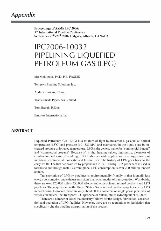
LPGs are hydrocarbon products in the C3-C4 range, propane and butane constituting the main components of them. These products, gaseous at normal temperature and pressure conditions, can be liquefied under high pressure and therefore can be handled very easily. The chemistry of commercial propane (C3H8) and butane (C4H10: n- and iso-butanes) is illustrated in Figure 1. Depending on the source and how it has been produced, small con-centrations of other hydrocarbons may also be present in LPG.
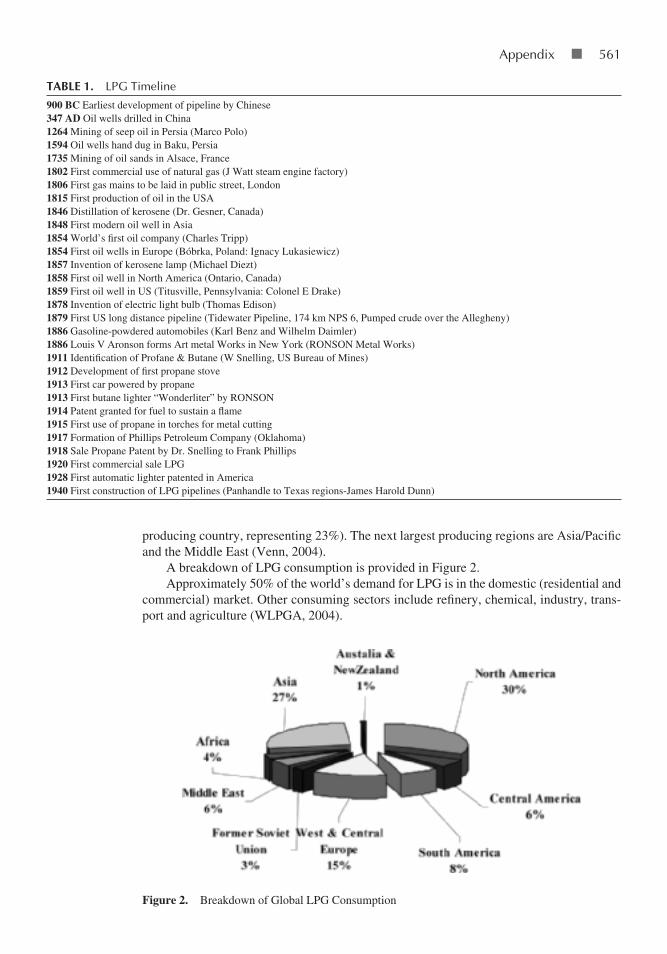
LPG was not identified until the early 1900s. Prior to that time, gasoline would evapo-rate while in storage due to inadequate refining techniques. Dr Snelling discovered that the gases which evaporated could be condensed and stored as a liquid at moderate temperatures and pressures. By 1911, he had isolated and identified these gases as propane and butane, the two major components of LPGs. The timeline of major events leading to identification, use and the construction of the first LPG pipeline systems is provided in Table 1 (SJGS, 2002, Mohitpour, et al, 2000 & Govt of Canada).
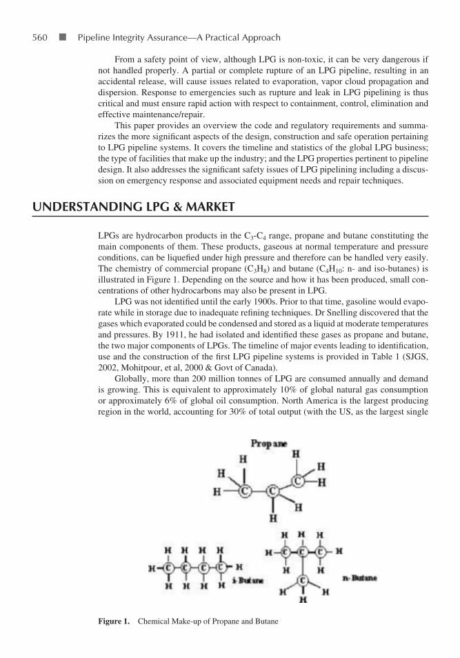
Globally, more than 200 million tonnes of LPG are consumed annually and demand is growing. This is equivalent to approximately 10% of global natural gas consumption or approximately 6% of global oil consumption. North America is the largest producing region in the world, accounting for 30% of total output (with the US, as the largest single
Figure 1. Chemical Make-up of Propane and Butane
Downloaded From: http://ebooks.asmedigitalcollection.asme.org/ on 09/07/2018 Terms of Use: http://www.asme.org/about-asme/terms-of-use
appendix ■ 561
producing country, representing 23%). The next largest producing regions are Asia/Pacific and the Middle East (Venn, 2004).
A breakdown of LPG consumption is provided in Figure 2.Approximately 50% of the world’s demand for LPG is in the domestic (residential and
commercial) market. Other consuming sectors include refinery, chemical, industry, trans-port and agriculture (WLPGA, 2004).
tAbLe 1. lPg timeline
900 BC Earliest development of pipeline by Chinese347 AD Oil wells drilled in China1264 Mining of seep oil in Persia (Marco Polo)1594 Oil wells hand dug in Baku, Persia1735 Mining of oil sands in Alsace, France1802 First commercial use of natural gas (J Watt steam engine factory)1806 First gas mains to be laid in public street, London1815 First production of oil in the USA1846 Distillation of kerosene (Dr. Gesner, Canada)1848 First modern oil well in Asia1854 World’s first oil company (Charles Tripp)1854 First oil wells in Europe (Bóbrka, Poland: Ignacy Lukasiewicz)1857 Invention of kerosene lamp (Michael Diezt)1858 First oil well in North America (Ontario, Canada)1859 First oil well in US (Titusville, Pennsylvania: Colonel E Drake)1878 Invention of electric light bulb (Thomas Edison)1879 First US long distance pipeline (Tidewater Pipeline, 174 km NPS 6, Pumped crude over the Allegheny)1886 Gasoline-powdered automobiles (Karl Benz and Wilhelm Daimler)1886 Louis V Aronson forms Art metal Works in New York (RONSON Metal Works)1911 Identification of Profane & Butane (W Snelling, US Bureau of Mines)1912 Development of first propane stove1913 First car powered by propane1913 First butane lighter “Wonderliter” by RONSON1914 Patent granted for fuel to sustain a flame1915 First use of propane in torches for metal cutting1917 Formation of Phillips Petroleum Company (Oklahoma)1918 Sale Propane Patent by Dr. Snelling to Frank Phillips1920 First commercial sale LPG1928 First automatic lighter patented in America1940 First construction of LPG pipelines (Panhandle to Texas regions-James Harold Dunn)
Figure 2. Breakdown of Global LPG Consumption
Downloaded From: http://ebooks.asmedigitalcollection.asme.org/ on 09/07/2018 Terms of Use: http://www.asme.org/about-asme/terms-of-use
562 ■ Pipeline Integrity assurance—a Practical approach
Propane is the most common liquefied petroleum gas. In the United States, the first commercial sales of propane were made in the 1920s. In 1922, when the US Bureau of Mines began tracking sales, 223,000 gallons were sold across the country. By 2004, US consumption of propane reached over 15 billion gallons for home, agriculture, industrial and commercial uses (PERC).
The majority of US supply is produced internally with imports making up about 10% of the country’s supply. The primary mode of transporting propane within the United States is by approximately 70,000 miles (>110,000 km) of interstate pipelines in a batched form. This system is most developed along the Gulf Coast and in the Midwest. Imports come by pipeline and railcar from Canada as well as by sea from countries such as Algeria, Saudi Arabia, Nigeria, Venezuela and Norway (EIA, 2006).
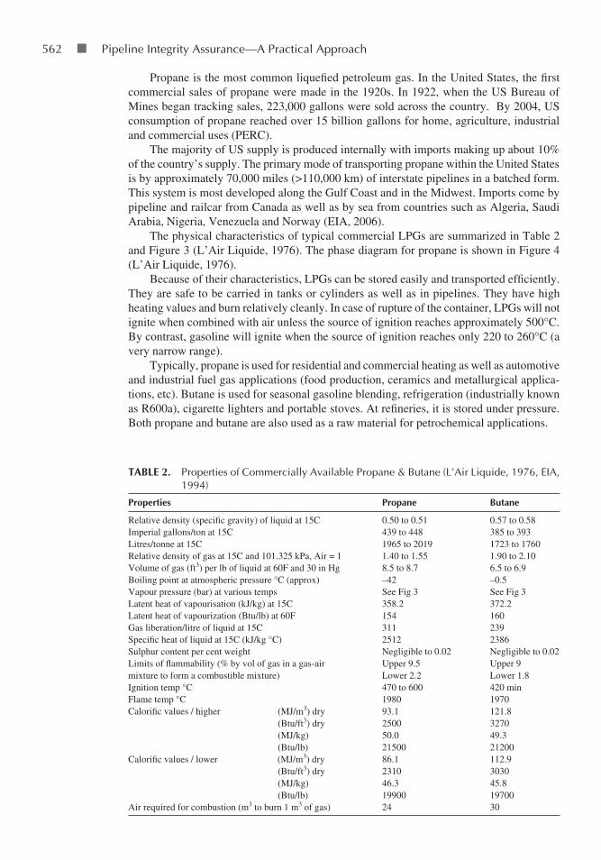
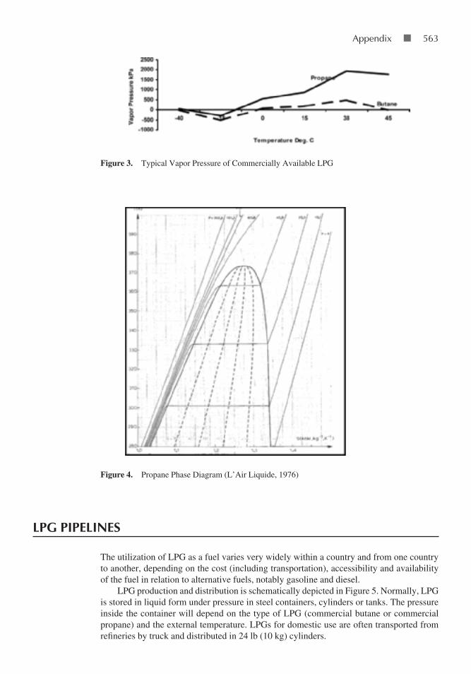
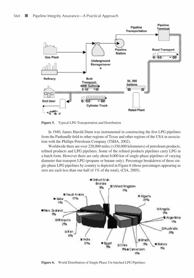
The physical characteristics of typical commercial LPGs are summarized in Table 2 and Figure 3 (L’Air Liquide, 1976). The phase diagram for propane is shown in Figure 4 (L’Air Liquide, 1976).
Because of their characteristics, LPGs can be stored easily and transported efficiently. They are safe to be carried in tanks or cylinders as well as in pipelines. They have high heating values and burn relatively cleanly. In case of rupture of the container, LPGs will not ignite when combined with air unless the source of ignition reaches approximately 500°C. By contrast, gasoline will ignite when the source of ignition reaches only 220 to 260°C (a very narrow range).
Typically, propane is used for residential and commercial heating as well as automotive and industrial fuel gas applications (food production, ceramics and metallurgical applica-tions, etc). Butane is used for seasonal gasoline blending, refrigeration (industrially known as R600a), cigarette lighters and portable stoves. At refineries, it is stored under pressure. Both propane and butane are also used as a raw material for petrochemical applications.
tAbLe 2. Properties of Commercially available Propane & Butane (l’air liquide, 1976, eIa, 1994)
Properties Propane butane
Relative density (specific gravity) of liquid at 15C 0.50 to 0.51 0.57 to 0.58Imperial gallons/ton at 15C 439 to 448 385 to 393Litres/tonne at 15C 1965 to 2019 1723 to 1760Relative density of gas at 15C and 101.325 kPa, Air = 1 1.40 to 1.55 1.90 to 2.10Volume of gas (ft3) per lb of liquid at 60F and 30 in Hg 8.5 to 8.7 6.5 to 6.9Boiling point at atmospheric pressure °C (approx) –42 –0.5Vapour pressure (bar) at various temps See Fig 3 See Fig 3Latent heat of vapourisation (kJ/kg) at 15C 358.2 372.2Latent heat of vapourization (Btu/lb) at 60F 154 160Gas liberation/litre of liquid at 15C 311 239Specific heat of liquid at 15C (kJ/kg °C) 2512 2386Sulphur content per cent weight Negligible to 0.02 Negligible to 0.02Limits of flammability (% by vol of gas in a gas-air mixture to form a combustible mixture)
Upper 9.5Lower 2.2
Upper 9Lower 1.8
Ignition temp °C 470 to 600 420 minFlame temp °C 1980 1970Calorific values / higher (MJ/m3) dry (Btu/ft3) dry (MJ/kg) (Btu/lb)
93.1250050.021500
121.8327049.321200
Calorific values / lower (MJ/m3) dry (Btu/ft3) dry (MJ/kg) (Btu/lb)
86.1231046.319900
112.9303045.819700
Air required for combustion (m3 to burn 1 m3 of gas) 24 30
Downloaded From: http://ebooks.asmedigitalcollection.asme.org/ on 09/07/2018 Terms of Use: http://www.asme.org/about-asme/terms-of-use
appendix ■ 563
LPg PiPeLines
The utilization of LPG as a fuel varies very widely within a country and from one country to another, depending on the cost (including transportation), accessibility and availability of the fuel in relation to alternative fuels, notably gasoline and diesel.
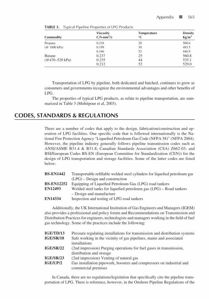
LPG production and distribution is schematically depicted in Figure 5. Normally, LPG is stored in liquid form under pressure in steel containers, cylinders or tanks. The pressure inside the container will depend on the type of LPG (commercial butane or commercial propane) and the external temperature. LPGs for domestic use are often transported from refineries by truck and distributed in 24 lb (10 kg) cylinders.
Figure 3. Typical Vapor Pressure of Commercially Available LPG
Figure 4. Propane Phase Diagram (L’Air Liquide, 1976)
Downloaded From: http://ebooks.asmedigitalcollection.asme.org/ on 09/07/2018 Terms of Use: http://www.asme.org/about-asme/terms-of-use
564 ■ Pipeline Integrity assurance—a Practical approach
In 1940, James Harold Dunn was instrumental in constructing the first LPG pipelines from the Panhandle field to other regions of Texas and other regions of the USA in associa-tion with the Phillips Petroleum Company (TSHA, 2002).
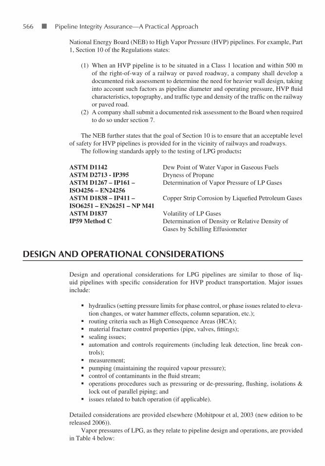
Worldwide there are over 220,000 miles (>350,000 kilometers) of petroleum products, refined products and LPG pipelines. Some of the refined products pipelines carry LPG in a batch form. However there are only about 8,000 km of single-phase pipelines of varying diameter that transport LPG (propane or butane only). Percentage breakdown of these sin-gle-phase LPG pipelines by country is depicted in Figure 6 (those percentages appearing as zero are each less than one half of 1% of the total), (CIA, 2005).
Figure 5. Typical LPG Transportation and Distribution
Figure 6. World Distribution of Single Phase Un-batched LPG Pipelines
Downloaded From: http://ebooks.asmedigitalcollection.asme.org/ on 09/07/2018 Terms of Use: http://www.asme.org/about-asme/terms-of-use
appendix ■ 565
Transportation of LPG by pipeline, both dedicated and batched, continues to grow as consumers and governments recognize the environmental advantages and other benefits of LPG.
The properties of typical LPG products, as relate to pipeline transportation, are sum-marized in Table 3 (Mohitpour et al, 2003).
codes, stAndArds & regULAtions
There are a number of codes that apply to the design, fabrication/construction and op-eration of LPG facilities. One specific code that is followed internationally is the Na-tional Fire Protection Agency “Liquefied Petroleum Gas Code (NFPA 58)” (NFPA 2004). However, the pipeline industry generally follows pipeline transmission codes such as ANSI/ASME B31.4 & B31.8; Canadian Standards Association (CSA) Z662-03; and BSI/European Codes BS-EN (European Committee for Standardization (CEN)) for the design of LPG transportation and storage facilities. Some of the latter codes are listed below:
BS-EN1442 Transportable refillable welded steel cylinders for liquefied petroleum gas (LPG) – Design and construction
BS-EN12252 Equipping of Liquefied Petroleum Gas (LPG) road tankersEN12493 Welded steel tanks for liquefied petroleum gas (LPG) – Road tankers
– Design and manufactureEN14334 Inspection and testing of LPG road tankers
Additionally, the UK International Institution of Gas Engineers and Managers (IGEM) also provides a professional and policy forum and Recommendations on Transmission and Distribution Practices for engineers, technologists and managers working in the field of fuel gas technology. Some of the practices include the following:
IGE/TD/13 Pressure regulating installations for transmission and distribution systemsIGE/SR/18 Safe working in the vicinity of gas pipelines, mains and associated
installationsIGE/SR/22 (2nd impression) Purging operations for fuel gases in transmission,
distribution and storageIGE/SR/23 (2nd impression) Venting of natural gasIGE/UP/2 Gas installation pipework, boosters and compressors on industrial and
commercial premises
In Canada, there are no regulations/legislation that specifically cite the pipeline trans-portation of LPG. There is reference, however, in the Onshore Pipeline Regulations of the
tAbLe 3. typical Pipeline Properties of lPg Products
commodityViscosityc/s-mm2/s
temperature°c
densitykg/m3
Propane(@ 1000 kPa)
0.2180.1990.166
203052
500.6483.5446.9
Butane(@470–520 kPa)
0.2370.2350.212
254452
560.8535.1529.0
Downloaded From: http://ebooks.asmedigitalcollection.asme.org/ on 09/07/2018 Terms of Use: http://www.asme.org/about-asme/terms-of-use
566 ■ Pipeline Integrity assurance—a Practical approach
National Energy Board (NEB) to High Vapor Pressure (HVP) pipelines. For example, Part 1, Section 10 of the Regulations states:
(1) When an HVP pipeline is to be situated in a Class 1 location and within 500 m of the right-of-way of a railway or paved roadway, a company shall develop a documented risk assessment to determine the need for heavier wall design, taking into account such factors as pipeline diameter and operating pressure, HVP fluid characteristics, topography, and traffic type and density of the traffic on the railway or paved road.
(2) A company shall submit a documented risk assessment to the Board when required to do so under section 7.
The NEB further states that the goal of Section 10 is to ensure that an acceptable level of safety for HVP pipelines is provided for in the vicinity of railways and roadways.
The following standards apply to the testing of LPG products:
ASTM D1142 Dew Point of Water Vapor in Gaseous FuelsASTM D2713 - IP395 Dryness of PropaneASTM D1267 – IP161 – ISO4256 – EN24256
Determination of Vapor Pressure of LP Gases
ASTM D1838 – IP411 – ISO6251 – EN26251 – NP M41
Copper Strip Corrosion by Liquefied Petroleum Gases
ASTM D1837 Volatility of LP GasesIP59 Method C Determination of Density or Relative Density of
Gases by Schilling Effusiometer
design And oPerAtionAL considerAtions
Design and operational considerations for LPG pipelines are similar to those of liq-uid pipelines with specific consideration for HVP product transportation. Major issues include:
hydraulics (setting pressure limits for phase control, or phase issues related to eleva-tion changes, or water hammer effects, column separation, etc.);
routing criteria such as High Consequence Areas (HCA); material fracture control properties (pipe, valves, fittings); sealing issues; automation and controls requirements (including leak detection, line break con-
trols); measurement;pumping (maintaining the required vapour pressure); control of contaminants in the fluid stream; operations procedures such as pressuring or de-pressuring, flushing, isolations &
lock out of parallel piping; andissues related to batch operation (if applicable).
Detailed considerations are provided elsewhere (Mohitpour et al, 2003 (new edition to be released 2006)).
Vapor pressures of LPG, as they relate to pipeline design and operations, are provided in Table 4 below:
Downloaded From: http://ebooks.asmedigitalcollection.asme.org/ on 09/07/2018 Terms of Use: http://www.asme.org/about-asme/terms-of-use

appendix ■ 567
sAfety And enVironmentAL considerAtions
LPGs contain negligible toxic components. However, abuse (as with solvents) is highly dangerous. The central nervous system will be stressed if overexposure occurs. Headache, dizziness, narcotic effect, and unconsciousness can occur. Butane has an exposure limit of 800 ppm. In large concentrations, LPG is an asphyxiant (displaces air) and therefore con-fined space releases are a major concern.
In combustion, LPGs have lower particulate emissions and lower noise levels relative to diesel, making propane attractive as a transportation fuel in urban areas. Noise levels can be less than 50% of equivalent engines using diesel. Some of the safety and environmental issues related to LPG are highlighted in NPGA, 2003.
LPg reLeAse And VAPor cLoUd
When an LPG pipeline ruptures, two conditions occur simultaneously: 1) flow of LPG from and out of the pipeline and 2) formation of a vapor cloud from and extending beyond the release location. These are described below:
1) Flow Within Pipeline After RuptureIn a rupture of a low vapor pressure (LVP) fluid pipeline, the spill (such as oil) flows from the pipeline and (depending on topography) drains off until all fluid within the pipe accounting for the change in the elevation profile is evacuated. In a high vapor pressure fluid pipeline (such as LPG), all the fluid within the pipeline will drain off irrespective of elevation profile. Unlike LVP, for which undulation in the elevation profile will help prevent total drainage of the pipeline upon rupture, the entire LPG contained in a section of a pipeline will boil and vaporize upon pipeline rupture and depressure to atmosphere. Such an account of LPG vaporization has been given by Mohitpour, et al, 2003.
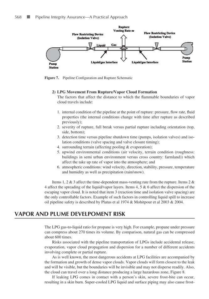
In a pipeline carrying HVP product, when a rupture occurs, the HVP fluid within the pipeline will experience an interface of liquid and gas. This interface will have the fluid liquefied under pipeline pressure on one side (higher than the vapor pressure of the fluid) and it will be at a lower pressure and gaseous on the other side (below the vapor pressure of the fluid). The location of the interface is time dependent and changes as the mass of fluid is removed from the pipeline. The mass of the fluid (liquid/gas) thus discharged at the rupture location is also time depend-ent and generally non linear with respect to time. Morrow et al, 1983, describe this phenomena and provide a technique for venting LPG through a segment of pipeline between isolation valves subject to a full rupture (Figure 7).
tAbLe 4. Propane and n-Butane Vapor Pressures
Vapor Pressure kPa
temperature °c Propane butane
–10 256 –40 388 4010 552 9520 757 17230 1004 26637.8 1218 362
Downloaded From: http://ebooks.asmedigitalcollection.asme.org/ on 09/07/2018 Terms of Use: http://www.asme.org/about-asme/terms-of-use
568 ■ Pipeline Integrity assurance—a Practical approach
2) LPG Movement From Rupture/Vapor Cloud FormationThe factors that affect the distance to which the flammable boundaries of vapor cloud travels include:
1. internal condition of the pipeline at the point of rupture: pressure, flow rate, fluid properties (the internal conditions change with time after rupture as described previously);
2. severity of rupture, full break versus partial rupture including orientation (top, side, bottom);
3. detection time versus pipeline shutdown time (pumps, isolation valves) and iso-lation conditions (valve spacing and valve closure timing);
4. surrounding terrain (affecting pooling & evaporation);5. upwind environmental conditions (air velocity, terrain condition (roughness:
buildings in semi urban environment versus cross country: farmland)) which affect the take up rate of vapor into the atmosphere; and
6. atmospheric conditions: wind velocity, direction, stability, pressure, temperature and humidity as well as precipitation (rain/snow).
Items 1, 2 & 3 affect the time-dependent mass-venting rate from the rupture. Items 2 & 4 affect the spreading of the liquid/vapor layers. Items 4, 5 & 6 affect the dispersion of the escaping vapor cloud. It is noted that item 3 (reaction time and isolation valve spacing) are the only controllable factors. Example of such factors in controlling liquid spill to increase oil pipeline safety is described by Platus et al 1974 & Mohitpour et al 2003 & 2004.
VAPor And PLUme deVeLPoment risk
The LPG gas-to-liquid ratio for propane is very high. For example, propane under pressure can compress about 270 times its volume. By comparison, natural gas can be compressed about 600 times.
Risks associated with the pipeline transportation of LPGs include accidental release, evaporation, vapor cloud propagation and dispersion for a number of different accidents involving complete or partial rupture.
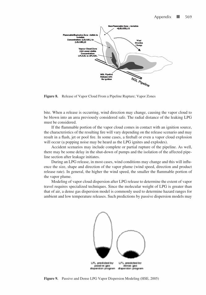
As is well known, the most dangerous accidents at LPG facilities are accompanied by the formation and growth of dense vapor clouds. Vapor clouds will form closest to the leak and will be visible, but the boundaries will be invisible and may not disperse readily. Also, the cloud can travel over a long distance producing a large hazardous zone, Figure 8.
If leaking LPG comes in contact with a person’s skin, severe frost-bite can occur, resulting in a skin burn. Super-cooled LPG liquid and surface piping may also cause frost-
PumpStation
PumpStation
RuptureVenting Rate m.
Flow Restricting Device(Isolation Valve)
Flow Restricting Device(Isolation Valve)
Liquid/gas Interface Liquid/gas Interface
GasLiquid
PumpStation
PumpStation
RuptureVenting Rate m.
Flow Restricting Device(Isolation Valve)
Flow Restricting Device(Isolation Valve)
Liquid/gas Interface Liquid/gas Interface
GasLiquid
PumpStation
PumpStation
RuptureVenting Rate m.
Flow Restricting Device(Isolation Valve)
Flow Restricting Device(Isolation Valve)
Liquid/gas Interface Liquid/gas Interface
GasLiquid
PumpStation
PumpStation
RuptureVenting Rate m.
Flow Restricting Device(Isolation Valve)
Flow Restricting Device(Isolation Valve)
Liquid/gas Interface Liquid/gas Interface
GasLiquid
Figure 7. Pipeline Configuration and Rupture Schematic
Downloaded From: http://ebooks.asmedigitalcollection.asme.org/ on 09/07/2018 Terms of Use: http://www.asme.org/about-asme/terms-of-use
appendix ■ 569
bite. When a release is occurring, wind direction may change, causing the vapor cloud to be blown into an area previously considered safe. The radial distance of the leaking LPG must be considered.
If the flammable portion of the vapor cloud comes in contact with an ignition source, the characteristics of the resulting fire will vary depending on the release scenario and may result in a flash, jet or pool fire. In some cases, a fireball or even a vapor cloud explosion will occur (a popping noise may be heard as the LPG ignites and explodes).
Accident scenarios may include complete or partial rupture of the pipeline. As well, there may be some delay in the shut-down of pumps and the isolation of the affected pipe-line section after leakage initiates.
During an LPG release, in most cases, wind conditions may change and this will influ-ence the size, shape and direction of the vapor plume (wind speed, direction and product release rate). In general, the higher the wind speed, the smaller the flammable portion of the vapor plume.
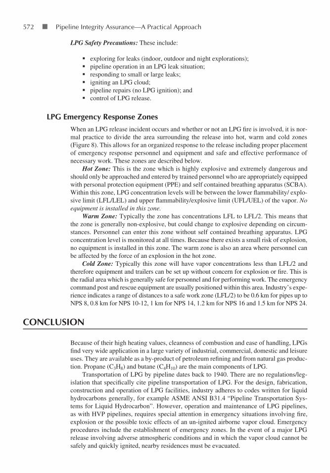
Modeling of vapor cloud dispersion after LPG release to determine the extent of vapor travel requires specialized techniques. Since the molecular weight of LPG is greater than that of air, a dense gas dispersion model is commonly used to determine hazard ranges for ambient and low temperature releases. Such predictions by passive dispersion models may
Flammable/Explosive Zone visible to invisible
Concentration: (LEL/UEL) to (LEL/UEL)/2
Non-Flammable Zone – invisible<(LEL/UEL) /2
NGL PipelineRelease with No ignition NGL Pipeline
Vapour Cloud Zone (rich zone) visible
Concentration: LFL/LEL to UFL/UEL
WindDirection Change
Flammable/Explosive Zone visible to invisible
Concentration: (LEL/UEL) to (LEL/UEL)/2
Non-Flammable Zone – invisible<(LEL/UEL) /2
NGL PipelineRelease with No ignition NGL Pipeline
Vapour Cloud Zone (rich zone) visible
Concentration: LFL/LEL to UFL/UEL
WindDirection Change
Flammable/Explosive Zone visible to invisible
Concentration: (LEL/UEL) to (LEL/UEL)/2
Non-Flammable Zone – invisible<(LEL/UEL) /2
NGL PipelineRelease with No ignition NGL Pipeline
Vapour Cloud Zone (rich zone) visible
Concentration: LFL/LEL to UFL/UEL
WindDirection Change
Figure 8. Release of Vapor Cloud From a Pipeline Rupture; Vapor Zones
Figure 9. Passive and Dense LPG Vapor Dispersion Modeling (HSE, 2005)
Downloaded From: http://ebooks.asmedigitalcollection.asme.org/ on 09/07/2018 Terms of Use: http://www.asme.org/about-asme/terms-of-use

570 ■ Pipeline Integrity assurance—a Practical approach
be optimistic or pessimistic as indicated by Figure 9. A safety report that uses a passive dis-persion model (based on Lower Flammability Limit, LFL) will overestimate the down wind extent of a flash fire but underestimate its width. Therefore, the use of a passive dispersion model must be properly justified, recognizing the inability of the model to correctly predict the width of the flammable cloud (HSE, 2005).
LPg PiPeLine mAintenAnce
Maintenance requirements for LPG pipelines are similar to those of other liquid hydrocar-bon pipelines. These generally include condition assessment; cathodic protection; leak and right of way surveys and maintenance (including geotechnical works); pipeline repair; fail-ure analysis; locating and marking of facilities appurtenances; valve inspection and repair; regulator maintenance; and management of compliance records.
HVP and LVP liquid pipeline maintenance differ only as to how a response is initiated and how work is performed in an emergency situation that may involve a pipeline leak, rupture, or fluid release.
Liquid (low or high vapor pressure) releases must be quickly contained to prevent ex-tensive environmental damage and the clean up operation should begin as soon as possible using a variety of means to recover the product. Subsequently, measures will be required to remediate and monitor the affected areas, but this is generally outside the scope of any contingency/emergency response planning.
emergency resPonse
Public safety is the top priority in any pipeline emergency response. “Emergency ” is de-fined as any unforeseen combination of circumstances or disruption of normal operating conditions that poses a potential threat to human life, health, environment or property if not contained, controlled or eliminated. Types of emergencies include:
vapor release inside or near a building;fire involving a pipeline facility;
Figure 10. An LPG Pipeline Fire, PVFD 2005. (Image Courtesy of KTAB-TV)
Downloaded From: http://ebooks.asmedigitalcollection.asme.org/ on 09/07/2018 Terms of Use: http://www.asme.org/about-asme/terms-of-use

appendix ■ 571
explosion near or involving a pipeline facility;natural disasters;emergencies involving other pipelines; andarson/bomb threats.
There are three potential risks associated with the failure of an LPG pipeline and the re-lease of LPG into the surrounding environment. These include: the risk of fire (Figure 10); a vapor cloud explosion; and the possibility of toxic effects of an un-ignited airborne vapor cloud (as a consequence, for example, of small quantities of mercury (if present) in the gas/product).
regulations/standardsRegulation, standards and safety rules for the transportation of LPG and the response to emergency situations include:
ASME ANSI B31.4 “Pipeline Transportation Systems for Liquid Hydrocarbon and Other Liquids”;
API 1160 “Integrity Management of Liquid Hydrocarbon Pipelines”;ASME B31.8S “Managing System Integrity of Gas Pipelines”;US Department of Transportation (DOT), Code of Federal Regulations (CFR) -
Regulation 195 (Pipeline Safety); andOccupational Health and Safety Act OHSA (Act 85 of 1993) and OHSA Process
Safety Management.
flaring LPgMost pipeline operating plans permit the flaring and venting of associated gas under the following circumstances:
for safety reasons; for unavoidable technical reasons (such as purge venting/emergency); andin emergencies (emergency transportation stops, compression, and others).
As most flaring situations in LPG pipeline transmission are related to emergencies, measurement and monitoring are not applicable. Flaring and venting under these circum-stances does not normally require regulatory approval.
responding to LPg emergenciesIdentifying LPG Leaks: Pressure drops related to LPG leaks are rarely identified at a pipe-line control center, except in the event of a major rupture. This is due to the fact that LPGs have high vapor pressure and compressibility (e.g., propane can be compressed by as much as 5% if pressure is raised to 1,000 psi). Leaks are generally reported by someone in the vicinity of the leak site. Some indications of an LPG leak include:
a cloud of steam or mist, caused by condensation and freezing moisture;ice build-up on exposed pipe and frozen ground around an underground pipe;brown vegetation, which is an indication of soil saturation;yellow-stained snow, which may be an indication of LPG accumulation under the
snow; andodor of condensed LPG.
Downloaded From: http://ebooks.asmedigitalcollection.asme.org/ on 09/07/2018 Terms of Use: http://www.asme.org/about-asme/terms-of-use
572 ■ Pipeline Integrity assurance—a Practical approach
LPG Safety Precautions: These include:
exploring for leaks (indoor, outdoor and night explorations);pipeline operation in an LPG leak situation;responding to small or large leaks;igniting an LPG cloud;pipeline repairs (no LPG ignition); andcontrol of LPG release.
LPg emergency response ZonesWhen an LPG release incident occurs and whether or not an LPG fire is involved, it is nor-mal practice to divide the area surrounding the release into hot, warm and cold zones (Figure 8). This allows for an organized response to the release including proper placement of emergency response personnel and equipment and safe and effective performance of necessary work. These zones are described below.
Hot Zone: This is the zone which is highly explosive and extremely dangerous and should only be approached and entered by trained personnel who are appropriately equipped with personal protection equipment (PPE) and self contained breathing apparatus (SCBA). Within this zone, LPG concentration levels will be between the lower flammability/ explo-sive limit (LFL/LEL) and upper flammability/explosive limit (UFL/UEL) of the vapor. No equipment is installed in this zone.
Warm Zone: Typically the zone has concentrations LFL to LFL/2. This means that the zone is generally non-explosive, but could change to explosive depending on circum-stances. Personnel can enter this zone without self contained breathing apparatus. LPG concentration level is monitored at all times. Because there exists a small risk of explosion, no equipment is installed in this zone. The warm zone is also an area where personnel can be affected by the force of an explosion in the hot zone.
Cold Zone: Typically this zone will have vapor concentrations less than LFL/2 and therefore equipment and trailers can be set up without concern for explosion or fire. This is the radial area which is generally safe for personnel and for performing work. The emergency command post and rescue equipment are usually positioned within this area. Industry’s expe-rience indicates a range of distances to a safe work zone (LFL/2) to be 0.6 km for pipes up to NPS 8, 0.8 km for NPS 10-12, 1 km for NPS 14, 1.2 km for NPS 16 and 1.5 km for NPS 24.
concLUsion
Because of their high heating values, cleanness of combustion and ease of handling, LPGs find very wide application in a large variety of industrial, commercial, domestic and leisure uses. They are available as a by-product of petroleum refining and from natural gas produc-tion. Propane (C3H8) and butane (C4H10) are the main components of LPG.
Transportation of LPG by pipeline dates back to 1940. There are no regulations/leg-islation that specifically cite pipeline transportation of LPG. For the design, fabrication, construction and operation of LPG facilities, industry adheres to codes written for liquid hydrocarbons generally, for example ASME ANSI B31.4 “Pipeline Transportation Sys-tems for Liquid Hydrocarbon”. However, operation and maintenance of LPG pipelines, as with HVP pipelines, requires special attention in emergency situations involving fire, explosion or the possible toxic effects of an un-ignited airborne vapor cloud. Emergency procedures include the establishment of emergency zones. In the event of a major LPG release involving adverse atmospheric conditions and in which the vapor cloud cannot be safely and quickly ignited, nearby residences must be evacuated.
Downloaded From: http://ebooks.asmedigitalcollection.asme.org/ on 09/07/2018 Terms of Use: http://www.asme.org/about-asme/terms-of-use
appendix ■ 573
referenCesCIA, The World Factbook, 2005, “Pipelines”, http://www.odci.gov/cia/publications/factbook/fields/2117.
htmlEIA (Energy Information Administration), 1994 “Alternatives to Traditional Transportation Fuels:An Over-
view”, Report DOE/EIA-0585/O - Distribution Category UC-98, June, http://tonto.eia.doe.gov/FTPROOT/alternativefuels/0585o.pdf
EIA (Energy Information Administration), 2006, “Propane Prices: What Consumers Should Know Bro-chure”, http://www.eia.doe.gov/neic/brochure/propane04/Chapter1.htm
Government of Canada, Canada’s Digital Collections; “Black Gold, Canada’s Oil Heritage: Charles Tripp”; http://collections.ic.gc.ca/blackgold/people/trippstory.html
HSE (Health & Safety Executive), 2005 “Safety Report Assessment Guide:LPG - Criteria”, http://www.hse.gov.uk/comah/index.htm
L’Air Liquide, 1976, “Gas Encyclopedia”, Elsevier, The NetherlandsMohitpour, M., Dawson. J., Babuk, T. & Jenkins, A., 2000 “Concepts for Increased Natural Gas Supply – A
pipeline Perspective”, presented at Forum 11, 16th World Petroleum Congress, Calgary, AB, Canada, June 11–15
Mohitpour, M., Golshan, H. & Murray, A., 2003, “Pipeline Design & Construction – A Practical Approach”, 2nd Edition, ASME Press, New York.
Mohitpour, M., Golshan, H. & Murray, A., 2006, “Pipeline Design & Construction – A Practical Approach”, 3rd Edition, (to be released), ASME Press, New York
Mohitpour, M., Trefanenko, Bill, Tolmasquim, S. T. & Kossatz, H, 2004, “Valve Automation to Increase Oil Pipeline Safety”, AMSE 5th International Pipeline Conference, Hyatt Regency, Calgary, AB, Canada, Oct 4–8
Mohitpour, M., Trefanenko, Bill, Tiomno Tolmasquim, Sueli & Kossatz Helmut 2003, “Oil Pipeline Valve Automation for Spill Reduction”, Rio Pipeline Conference & Exposition, Hotel Inter-Continental, Oct 21-24
Morrow, T. B., Bass, R. L. & Lock J. A, 1983, “An LPG Pipeline Break Flow Model”, ASME Transaction, Jr. Energy Resources Tech. Vol. 105 pp 379-387, Sept
NPGA (National Propane Gas Association), 2003, http://www.npga.org/i4a/pages/index.cfm?pageid=466PERC (Propane Education & Research Council), “The History of Propane”, http://www.propanecouncil.
org/files/The%20History%20of%20Propane.pdfPVFD (Potosi Volunteer Fire Department), 2005, “Pictures of 9/7/2000 LPG Pipeline Fire”, http://www.
angelfire.com/tx/pvfd/pipeline.htmlPlatus, D. L., Mackenzie D. W. & Morse, C. P., 1974 “Rapid Shutdown of Failed Pipeline Systems and Limit-
ing Pressure to Prevent Pipeline Failure Due to Over Pressure” Part 1, Report MRI-2628- TRI, OctSJGS (San Joaquin Geological Society), 2002, “The History of the Oil Industry”, http://www.sjgs.com/his-
tory.html#ancient_to_presentTSHA (The Texas State Historical Association), 2002 “The Handbook of Texas Online”, http://www.tsha.
utexas.edu/handbook/online/ Venn, J., 2004, “Rapid Access to Modern Energy Services Using LP Gas”, 19th World Energy Congress, Sydney,
Australia, Sept 5-9WLPGA (World LP Gas Association), 2004, “Global LP Gas Statistics”, http://www.worldlpgas.com/v2/
ressources.php?id=04
Downloaded From: http://ebooks.asmedigitalcollection.asme.org/ on 09/07/2018 Terms of Use: http://www.asme.org/about-asme/terms-of-use

Downloaded From: http://ebooks.asmedigitalcollection.asme.org/ on 09/07/2018 Terms of Use: http://www.asme.org/about-asme/terms-of-use

575
AAbrasion resistance, 149–150Abrasive blasting, 166, 168Advantica, 335Alternative integrity verification
(AIV), 12–13Aluminum anodes, 192, see also
Sacrificial anodesAmerican Gas Association
(AGA), 36, 320American Petroleum Institute, see
API entriesAPI 1104, 339, 353API 1130, 35API 1160, 39, 68, 74–77, 96,
379–380, 382API 1163
definitions provided in, 271ILI Systems Qualifications
Standard, 238verification process, 242
API 5L standard, 288–289API X120, 6API X100-API X120, 15ASME (American Society of
Mechanical Engineers)B31G manual, 31pipeline codes B31.4 and
B31.8, 35–36, 320, 383ASME B31.8S, 74, 77–79, 96,
97, 238performance measures from,
106pipeline integrity standard,
280threat-specific performance
metrics from, 105ASNT ILI-PQ, 240ASTM E-1820, 294Axial stress, 282
BBackfill material, low-resistance,
179
Backfill/terrain characteristics, 154Background data collection
phase, 432–433Balloons (inflatable plugs),
376–377Barlow formula, 6, 281Barrier coating, 19–20, 122–123,
see also Corrosionresistance, 136–137
Baseline assessment plan (BAP), 90–92, 94, 533
process documentation, 92–93Battelle, 323Bauschinger effect, 275Bending stress, 283B31G (2009) assessment
criterion, 332BG Technology, 335, 336, see
also BG TechnologyBlast effects, 491
from point of rupture to safe radiation heat distance, 493
Bridging bar, 318British Gas (BG), 323–324Brittle fracture, 477Buried pipelines
CP calculations for, 203–208ground marking of, 397
CCaliper tool, 245Canadian CSA Z 662-07
standard, 293, 339, 414Canadian pipeline regulations,
see NEBCarbon equivalent (CE), 358Cathodic disbondment, 134
tests, 139–141Cathodic protection (CP)
methodsgalvanic current system,
186–189impressed current system,
183–185
Cathodic protection (CP) potential, arrangement for measurement of, 201–202
Cathodic protection (CP) systems, 18, 20–22, 122, 138, see also Corrosion
applicable standards and procedures, 181–182
calculations for buried pipelines, 203–205
cased crossing test stations, 224–225
criteria for, 202design considerations,
195–196design problems, 210–216electrical interference effects
from, 222–224equipment protection and
safety issues, 233–235factors influencing the
requirement for, 182–183foreign line crossing test
stations, 225impressed current anodes
calculations, 209–210installation, 196–200insulating flange test stations,
226maintenance, 216–218monitoring, 200–201multimeter or portable
voltmeter, 226–228operational aspects, 219–221records, 202–203reference electrodes/cells or
half cells, 228remedial measures, 233requirement of, 179–181survey, 228–229test stations for surveying of,
224–225Cells or half cells, 228Change of service, 417–419
INDEX
Downloaded From: http://ebooks.asmedigitalcollection.asme.org/ on 09/07/2018 Terms of Use: http://www.asme.org/about-asme/terms-of-use
576 ■ Pipeline Integrity Assurance—A Practical Approach
Charpy Vee notch (CVN)impact energy, 339testing, 291–292
Chemical resistance, 134–135, see also Coating applications
Chevron-type markings, 477CIPS (Close Interval Potential
Survey) technique, 229Close interval survey (CIS), 201,
268Coating applications
advantages/disadvantage, 125ambient conditions, 164applicable coating standards,
123–124application temperature,
164–165availability, 154characteristics and limitations
of, 126chemical resistance, 134, 136code requirement for, 128cold weather application and,
159cost of, 157CP and, 122, 127–128electrical resistance, 136–137elements of successful,
160–162environmental conditions and,
159failures, 19inspection and testing, 162,
165–166North American pipeline
codes, 124–125operating range code, 127performance of, 123, 129, 168properties of, 154–156properties of external, 129–130safety considerations, 166SCC and, 127–128selection, 153specification and qualification,
154, 160–161surface preparation, 162–164tested, 166testing of, 130thickness, 141, 165transportation and storage, 166types of, 123
Coating failurescase studies, 168–170and causes, 166–168defined, 125–126modes, 168
Coating’s adhesion, 130–131testing, 132–134
Coke breeze, 179Cold weather application and
coatings, 159Compatibility/cathodic
disbondment, 138–141Composite reinforced gas
transportation products, 16Composite reinforced line pipes
(CRLP), 16Computational pipeline
monitoring (CPM), 35Constrained optimization, 516Construction damage in
pipelines, 29–30Construction defects, 276–277Corrosion, 26
assessment, 336cracking, 38defects, 31–32, 329–336,
382defined, 178forms of, 17–18mechanism of, 179and pipe defects, 279pits, 357prevention, 179
Corrosion repair techniquepermissibility of, 379
CP, see Cathodic protection (CP)
Cracking, see also Corrosionenvironmentally assisted
cracking (EAC), 27environmentally induced, 18stress corrosion, see Stress
corrosion cracking (SCC)
Crack-proof welding, 358Crack repair technique
permissibility of, 380Cracks, 477
detection, 244Crack tip opening angle (CTOA),
291, 294
Crack tip opening displacement (CTOD), 291, 294
toughness, 339Critical bonds, 232–233, see also
ShuntsCrosscut adhesion test, 132,
see also Coating’s adhesionCure time, 165Cyclic pressure tests, 324
DDCVG (Direct Current Voltage),
230, 268Defect
interaction, 337, 339sizing, 318–319
Defect assessmentcurves, construction of,
336–337, 338methods, 319–321
Denting of pipes, 276–277Dent(s), 322–326
fatigue assessment, plain, 326and gouges, 327–328
Depth micrometer, 318Det Norske Veritas (DnV), 336Differential aeration cells, 182Dioctyl phthalate, 167Disbonded coating, 130–131Document management system
(DMS), pipeline integrity, 108–109
document retention, 108filing guidelines, 107index scheme, 107review and revision plan,
113–115search and retrieval guidelines,
107–108typical pipeline integrity
management system, 109–113Dressing, see GrindingDrop-weight tear test (DWTT),
291–293, 294Ductile failure, 293Dugdale strip yield model, 340
EEconomic benefits of pipeline
technologies, 13, see also Pipeline technology
Downloaded From: http://ebooks.asmedigitalcollection.asme.org/ on 09/07/2018 Terms of Use: http://www.asme.org/about-asme/terms-of-use
Index ■ 577
Eddy current testing, 265Elastic plastic strip yield model,
330Electrical current, human
resistance to, 234Electrical interference effects
from CP, 222, see also Cathodic protection (CP)
remedial measures, 222–224stray currents, 221–222
Electrical resistance, 136–137Electrolysis, 21Electromagnetic acoustic
transducers (EMAT), 13, 254Electromagnetic acoustic
transmission, 249Emergency Response (ER)
aspects of pipeline construction as related, 456–460
codes, 460cooperation, essential
requirements, 441–442, 455–456
definition of, 440–441elements of, 442–443hazards leading to, 473–474incidences, 456, 472situations in pipeline
transmission, 443Emergency Response (ER) issues
estimated radiant heat release, 500–501
flame height estimation, 502–503heat generation in pool fire,
494–499heavy gases and liquids
pipeline safety and, 492–494point source view factor,
501–502pool fire volume/area/diameter,
499–500safe distance, 502surface emissive/transmissivity
power, 502Emergency management
role of, 443Emergency response planning
(ERP), 484background, 437–440definition, 443manual, 443–446
Encroachment management service (EMS), 401
Environmentally assisted cracking (EAC), 27, see also Cracking
Epoxy composition filled sleeve repairs, 361–363
European Pipeline Research Group (EPRG), 324–325, 339
Explosion (vapor cloud explosion/late explosion), 482
External corrosion direct assessment (ECDA), 268–269, see also Corrosion
ExxonMobil, 6
FFailure, see also Gas pipelines
failurecoating, 19defects and, 25–29of a flawed steel pipe, 340gas transmission, 37general causes of, 438major causes of, 320–321modes, 38, 272pressure ratio and prediction
methods, 337probability of, 51, 73stress, 332
Failure assessment curve (FAC), 342
Failure assessment diagram (FAD), 340–342
Fault tree, defined, 51Fiber-reinforced polymeric (FRP)
composites, 16–17Field evidence gathering,
424–430Field joint coating, 156, 158–159Fire and explosion, 481–482Fitness for service assessments,
413–416Flammable cloud, 480Flammable limits, 481Flash fire, 482Flexibility of coatings, 146–148,
see also Coating applicationsFlow stress, 330
and failure criterion, 331and through wall flaw size, 330
Fluid couplant, 253Flux core arc welding (FCAW),
357Folias factors, 31–32, 322, 330,
334Fracture mechanics, 271, 298
and fatigue, 310–314fatigue loading, 307irregular loading, 316–318leak before rupture, 303–306life prediction, 314–316stress analysis of cracking,
301–303stress life approach, 308–310surface energy of a crack,
298–301Freeze plugging, 374–375Full-encirclement split sleeve
repair, 360Fusion bonded epoxy (FBE)
coating, 124, 127–128, 155, 165, 166, 167, 168, 206
qualification requirements from RP0394-2002, 155, 156
GGalvanic corrosion, 183, see also
CorrosionGalvanic current system,
186–189Gas leak detection, 399Gas metal arc welding (GMAW),
357filler metal, 391
Gas pipeline developments, historical, 13
Gas pipelines failure, see also Failure
consequences of, 478consequences of natural gas
release, 485–487fire and explosion, 481–482flammable limits, 481heat affected zone/thermal
exposure, 487–488natural gas pipeline emergency
planning distances, 483–485natural gas pipeline fire dura-
tion, 479–480potential hazard in, 478–479
Downloaded From: http://ebooks.asmedigitalcollection.asme.org/ on 09/07/2018 Terms of Use: http://www.asme.org/about-asme/terms-of-use
578 ■ Pipeline Integrity Assurance—A Practical Approach
Gas Research Institute (GRI), 36, 320
Gas transmission failures, 37Geographical information system
(GIS), 238Geohazards in pipelines, 30Geometry ILI tools, 255GE-PII, 411Girth weld coating system, 153Gouges, 32, 321–323
and dents, 327–328Grade 690-Grade 931 (API
X100-API X120), 15Grinding
limitations and procedure, 355–357
Ground beds, 192–195, 216location, 195–196types of, 192–194
Ground marking of buried pipeline facilities, 397
HHall effect, 247Hardness resistance, 148–149Hard spots, 28HCA, see High-consequence
areas (HCA)Heat-affected zone (HAZ),
487–493toughness, super-high, 15Heat generation in pool fire,
494–499Heat input (HI), 391Heat radiation source
safe distance from, 489Heat shrink sleeves, 156, 158High-consequence areas (HCA),
39, 67identification, 42, 87–88for liquid pipelines, 83for natural gas pipelines, 84–87
Higher grade steels, manufacture of, 275
High-molecular-weight polyethylene (HMWPE) cable, 179
High-resolution tools, 255High-strength low-alloy steels
(HSLA), 6essential characteristics of,
14–15
High-vapor pressure (HVP) fluids, 439–440
Holidays, 122, 139detection, 165–166tests, 159
Hook crack, 274Hoop stress, 6, 281, 331–332Hot tapping, 368–370
procedure, 372–373Hot work safety precaution, 465Hot zone, 480HSE implementation in pipeline
construction, 466HTUFF, 15–16Human resistance to electrical
current, 234Hydrogen blistering, 28Hydrogen cracking, 388–389,
390Hydrostatic testing, 266–267
IILI, see Inline inspection (ILI)Impact resistance, 150–152Impact zones, 87–88Imperfections
undetected, 273–274Impermeable coating, 128Impressed current anodes, 184Impressed current system,
183–185Incident command system (ICS),
440, 446–448documentation controls and
resources, 453–454environment supervisor, 452ground rules, 454–455incident commander, 449–450liaison personnel, 451–452logistics, 452operations supervisor, 450planning group, 453procurement, 453public relations supervisor, 451reasons for, 448roles and responsibilities, 448safety management supervisor,
450–451technical specialists, 454
Incident control, 474Incident management design, 478Inflatable gasbags, 376–377
Inflatable plugs, 376–377Inline inspection (ILI), 25, 34,
95–96Inline inspection (ILI) tools,
23–24, 43, 237–238accuracy, 256–258data validation methods,
259–260for geometry survey, 244–246location accuracy, 258performance of, 238–244
In-service welding deposition, 357–358
Instability criterion, 330Integrity assessment, 516Integrity management planning,
530–532role of risk assessment in,
532–533Integrity management program
(IMP), see also Pipeline integrity management (PIM) programs
audit, 97, 102communication plan, 103–105data gathering and review of, 73definition of, 61developing the program, 394documentation of personnel
qualifications, 83documentation plan, 107–114evaluation, 115–118executing the program, 395ground movement, 401–407integrity management
reporting, 102–103introduction to the program,
79–80key elements of, 72–74leak detection, 399–401management of change plan,
105–107objective of, 59–60organizational structure for
decision making, 80performance improvement, 103principles of, 72purpose and scope, 80right-of-way surveillance,
395–398roles and responsibilities,
80–83
Downloaded From: http://ebooks.asmedigitalcollection.asme.org/ on 09/07/2018 Terms of Use: http://www.asme.org/about-asme/terms-of-use
Index ■ 579
statement of authority, 79tasks contained within, 394training and hiring
requirements, 83Integrity management rule
for gas and liquid pipelines, comparison of, 69
for gas pipelines, 68–69for hazardous liquid pipelines, 68for natural gas operators, 67
Intelligent inspection pigs (ILI), 523
Intergranular cracking mode, 27Internal coatings
applicable specifications for, 173
application, 173–175mitigating, 170–172
Internal corrosioncauses of, 170
Internal corrosion direct assessment (ICDA), 269
Internationally recognized standards, 61–62
JJet fire, 482Joint coatings, comparison, 157Joint completion systems
comparison of common, 158
KKAPA Spread Sheet, 335
LLaminations, 28Laser profiling inspection tool
(LPIT), 319Laser triangulation, 319Legal issues in failure
investigation, 435Light detection and ranging
(LIDAR), 399Limit states, 413Line current survey, 220Line patrols, 395Line relocation, 419–424Lipping effect, 31Liquid epoxy, 165Liquid pipeline
companies, 35regulations, 68
Load and resistance factor design (LFRD), 336
Log secant model, 329
MMagnesium anodes, 189, 190, see
also Sacrificial anodesMagnetic flux leakage (MFL),
244characterization/sizing
capabilities, 250detection anomalies, 249tools, 23–24, 246–249
Magnetic particle inspection (MPI), 261–263
Maintenance issues in pipelines, 35–38
Manufacturer’s safety data sheet (MSDS), 166
Material properties, 288–297Material toughness, 291Maximum allowable operating
pressure (MAOP), 31Mechanical clamps, 358Mechanical damage repair
techniquepermissibility of, 380
Mechanical plugging, 373–374Mechanical vapor plugs
(V-PLUG), 373–374Mechanized ultrasonic inspection
techniques, 12Mechanized welding, 11–12Meta data, 88Metal loss, 244Metallurgical examination,
conducting, 430–432Microbial corrosion (MIC), 166,
see also CorrosionMicrobial-induced internal
corrosion, 279, see also Corrosion
Mild steel, 291Miller’s plastic collapse model,
339–340Mill scale corrosion, 183Miner’s rule, 325–326Mohr’s circle, 285–286Mud plugs, 375–376Multimeter, 226–228MUSTR
definitions by, 203
NNational Association of
Corrosion Engineers (NACE), 35
Natural gas pipeline, see also Gas pipelines failure
emergency planning distances, 483–485
fire, duration of, 479–480Natural gas release
consequences of, 485–487NCF Industries, 16NEB (National Energy Board)
functions of, 69and OPR-99, 69–70requirements for pipeline
integrity, 70–72and Transportation Safety
Board (TSB) of Canada, 69–70NG18 surface flaw equations, 32Nippon Steel Corporation, 6, 15Nondestructive testing (NDT)
methods, 358Nonmetallic (composite) sleeves,
363–367Non-QRA methods, 535
index methods, 540–543model-based non-QRA,
543–544risk matrix methods, 536–540
OOdometer wheels, 251Operating temperature, 153–154Operational defects, 277–280OPR-99, 70, see also NEB
PPearson survey, 268Peel adhesion
constant rate of peel adhesion test, 145
hanging weight adhesion test, 144–145
Penetration resistance, 141Permanent sleeve repairs,
358–363PetroSleeve®, 359, 360Phased array testing, 265Pig-locating transmitters, 373Pipe
buckling, 280
Downloaded From: http://ebooks.asmedigitalcollection.asme.org/ on 09/07/2018 Terms of Use: http://www.asme.org/about-asme/terms-of-use

580 ■ Pipeline Integrity Assurance—A Practical Approach
cutout repair, 354defects and corrosion, 279
Pipeline and Hazardous Materials Safety Administration (PHMSA), 61
Pipeline cleaning, 240–241Pipeline coatings, see Coating
applicationsPipeline construction,
dustry safety guidelines for, 462–463
personal protective equipment (PPE), 463–464
small tool safety, 463Pipeline construction, risks
during, 466–467excavation, 470–472
landslide during construction, 468–470
Pipeline construction safetyother special safety
consideration during construction, 460–461
precautions for construction operations, 462
work site safety, 460Pipeline Control Center (PCC), 35Pipeline corrosion influencing
factors, 182–183, see also Corrosion
Pipeline defects, 25–26construction damage, 29–30geohazards, 30hard spots, 28hydrogen blistering, 28incorrect operations, 29laminations, 28manufacturing defects, 28third party/mechanical damage,
28–29Pipeline emergencies, 437–439,
456, 472, 475Pipeline failure, see FailurePipeline Hazardous Material
Safety Administration (PHMSA), 34
Pipeline incidence reductionsafety management in, 475–476
Pipeline incident management, 472, 474
causes of incident, 472, 474–475
Pipeline inspection gauge (PIG), 22–23
Pipeline inspection programs, basis of, 395
Pipeline integrityassessment methods, 92–95assessment techniques and risk
mitigation options, 94–97global codes addressing, 63–64Office of Pipeline Safety (OPS)
requirements for, 67Pipeline integrity inspection,
22–23defects and failures, 25–31high-resolution tools, 23–24technologies in, 23–25
Pipeline integrity management (PIM), 59, 73
Pipeline integrity management (PIM) programs, 39–40, see also Integrity management program (IMP)
adopted by pipeline industry, 41–42
appendix, 46–47communications plan, 45confirmatory direct assessment
(CDA), 45documentation plan, 46HCA identification, 42integrity assessment plan,
43–44management of change plan,
44–45performance measures plan, 45pipeline repair and remediation
plan, 43–44preventative and mitigative
measures plan, 44quality assurance plan, 45–46review and revision plan, 46risk assessment plan, 43
Pipeline integrity regulatory styles, 62, 65–66
Pipeline integrity-related documents, 61–62
Pipeline life cycle, 59Pipeline networks
liquid transmission lines, 1significance of, 2special transmission pipelines, 1types of, 2, 5
Pipeline Questionnaire, 239–240Pipeline rehabilitation, 417–419,
see also RepairsPipeline repairs, see RepairsPipeline Research Council
International (PRCI), 320Pipeline safety, see Pipeline
securityPipeline security, 13, 53–55
management program, 54–55modes of transportation and, 53security risk assessment, see
Pipeline security riskPipeline security risk, 55, 549
pipeline safety and security regulation, 550–551
pipeline security response, 551–552
pipeline security risk assessment plan (SRAP), 552–555
Pipeline stresses, 281–283Pipeline structural integrity,
34–35Pipeline technology
composite reinforced line pipe (CRLP), 16
construction technologies, 11–13
current development, 14–16fiber-reinforced polymeric
(FRP) composites, 16–17pressure and material, 6, 11
Pipeline transmissionemergency situations in, 443
Pipeline transportation, 166Pipeline warning signs, 397–398Pipe manufacture, 272Pipe storage, 166, 167Pipe supply
source of, 161–162Pipe-to-soil meters, 202Pipe-to-soil potential (PSP), 202,
216, 229Pipe wrinkling, 280Pit matching, 412–413Plastic collapse stress, 340Plastizers, 167Plate rolling process, 295Plugging
freeze, 374–375mechanical, 373–374
Downloaded From: http://ebooks.asmedigitalcollection.asme.org/ on 09/07/2018 Terms of Use: http://www.asme.org/about-asme/terms-of-use
Index ■ 581
Plugsballoons or inflatable, 376–377mud, 375–376
Polyethylene tapes, 167Pool fire, 482Portable voltmeter, 226–228Pressure effects on humans, 492Principal stresses, 284–285
theories of failure, 286–288Probabilistic risk assessment/
quantitative risk assessment (PRA/QRA), 51
Probability of detection (POD), 238
Probability of identification (POI), 238
Public awareness program, 104, see also Integrity management program (IMP)
Pull-off adhesion test, 131–132, see also Coating’s adhesion
Pulse echo technique, 264
QQRA, see Quantitative risk
assessment (QRA) methodsQuantitative risk assessment (QRA)
methods, 523, 533–535deterministic QRA example,
524–526limitations of the probabilistic
inference of operational data, 526–528
RRADARSAT-1 satellite, 405Ranking systems, 73Record of operating incidents,
435Rectifiers, 199–200
inspection/maintenance requirements, 231
meter readings, 231–232tap-adjusted air-cooled,
230–231tap-adjusted oil-cooled, 231
Reference electrodes, 228Regulatory requirements in
pipelines, 35–38Rehabilitation, 417–419Re-inspection and hydrostatic
re-testing intervals, 407
historic approach, 408–409interval validation using field
metrics, 409–410pit matching, 412–413run comparisons, 410–411statistical analysis, 411
Repair(s), 32, 96applications, 354coating, 153codes and standards for
making, 33grinding and dressing, 355–357history, 33in-service welding deposition,
357–358mechanical clamps, 358nonmetallic (composite)
sleeves, 363–367permanent sleeve repairs,
358–363pipe cutout and replacement, 354planning stage in, 352procedures, 353purpose of, 351relevant codes and standards
for making, 352–353sequence to affect, 351–352types of, 353
Repair, issues related tosafety, 383–386welding and hot tapping,
386–391Repair method selection
compliance with codes and standards, 379
repair strategy, 379–383Repair planning
elements in, 378historical review, 378repair pressure, 378
Report preparation, 433–435Re-rounding, 323Ring expansion test, 296Risk(s)
acceptance criteria and communication, 547–549
during pipeline construction, 466–467
tolerance, 52Risk analysis
plan, 88, 95steps in, 52–53
Risk assessment, 40, 46–48, 73, 76, 515–517
and analysis, 89–90history, 48–49security, 55
Risk assessment method, 50–53non-QRA, 535–544QRA, 533–535selection of, 544–547
Risk-based inspection (RBI) tools, 513
Risk management, 49–50, see also Risk assessment
consequence analysis, 521–523elements of, 513plan, 43preventive measures
implementation, 435Risk mitigation, 94–97
measures, 547R6 method, 340ROW signs, 398RSTRENG, 31, 41, 334, 335
SSacrificial anodes, 188Sacrificial anodes, characteristics
anode efficiency, 189–190current output, 189, 190–192ground beds, 192–195
Safety, 383–386, see also Pipeline security
SCADA system, 35, 53SCC, see Stress corrosion
cracking (SCC)Self-contained breathing
apparatus (SCBA), 480Shear wave transducer, 264–265Shunts, 232
converting mVDC to amperes, 232
types, 232–233Slack flow, 283Slope extensometers, 403Slope failure, 402, see also FailureSlope inclinometers, 404SMTS (Specified Minimum
Tensile Strength), 31SMYS (Specified Minimum
Yield Strength), 31Soil resistivities, 221
surveys, 268–269
Downloaded From: http://ebooks.asmedigitalcollection.asme.org/ on 09/07/2018 Terms of Use: http://www.asme.org/about-asme/terms-of-use

582 ■ Pipeline Integrity Assurance—A Practical Approach
Soil strain meter, 405Soil stressing resistance, 142, 144Split sleeve installation, 361Spring back, 323Standard caliper tools, 255Standards and procedures for CP
systems, 181–182, see also Cathodic protection (CP)
Standoff distance (SO), 252Stopple and bypass, 367hot tapping, 368–370Stopple procedure, 371Strain polarization, 141, see also
Cathodic disbondment, tests
Stray currents, 221Street evaluating laser methane
assessment (SELMA), 400Stress corrosion cracking (SCC),
13, 27, 38, 280, see also Cracking
high-pH, 27near-neutral pH, 27and pipeline coating, 127–128
Submerged arc method, 274–275Superpig curvature pig, 237Surface cleanliness, 156
TTap-adjusted air-cooled rectifiers,
230–231
Tap-adjusted oil-cooled rectifiers, 231
Tape coatings, 167Tensile properties, 294–296Tensile strength, 289–290Thermal exposure, 487–493Thermal stress, longitudinal, 282Thermo-mechanical controlled
rolling process (TMCP), 295Threat identification, 88–89,
517–521Three-layer polyethylene (3LPE)
coatings, 158–159, 165, 168Transportation Safety Board
(TSB) of Canada, 69Transverse flux tools, 254–255Tresca criterion, 287Tresca shear stress theory, 287
UUltrasonic crack detection tool, 251Ultrasonic testing, 263
pulse echo technique, 264Ultrasonic tools (UT), 244, 249–253
compression wave, 252, 253fluid couplant, 253for pipeline inspection, 23–24shear wave, 253specifications, 253
Ultrasound principle crack inspection, 251
Underwater inspection, 398United States pipeline
regulations, 66–69Unstable decomposition
of the flowing hydrocarbon product, 387–388
U.S. Code of Federal Regulations (CFR) Title 49, Part 195.452, 68
US Transportation Safety Administration (TSA) guidelines, 54
VVon Mises theory, 287–288
WWeathering resistance, 152–153Weld
cracks, 38, 357deposition, 357, 389
Weldability, 358Weld defects, 29–30, 32, 339–340
during submerged arc welding pipe manufacture, 275–276
Welding sleeve repair, 386–387
XX-cut knife adhesion test, 134,
see also Coating’s adhesion
Downloaded From: http://ebooks.asmedigitalcollection.asme.org/ on 09/07/2018 Terms of Use: http://www.asme.org/about-asme/terms-of-use