problem28 - crashwhite ·...
TRANSCRIPT

Problem 28.1 The EMF of a ba4ery measures the inherent power-‐producing, electric field generaCng character of the ba4ery. When current is drawn from the ba4ery (which is analogous to current passing through the ba4ery), the voltage difference across the ba4ery’s terminal is such that
1.)
ε
R
i
ΔVEMF = ε ΔVR = −iR
ΔVterminal = ε − iRΔVterminal = Vterminal = ε − iR ⇒ 11.6 V( ) = 15 V( ) − iR
⇒ i =3.4 V( )
RThe power raCng is:
P = i Vterminal
20 W( ) = 3.4 V( )R
!
"#
$
%& 11.6 V( )
⇒ R = 1.97 Ω
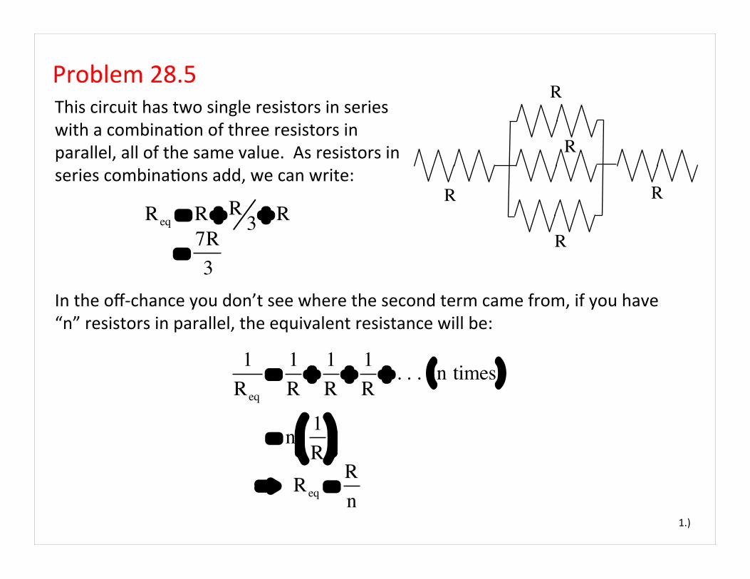
Problem 28.5 This circuit has two single resistors in series with a combinaCon of three resistors in parallel, all of the same value. As resistors in series combinaCons add, we can write:
1.)
R
Req = R + R3 + R
= 7R3
In the off-‐chance you don’t see where the second term came from, if you have “n” resistors in parallel, the equivalent resistance will be:
R
R
RR
1Req
=1R+
1R+
1R+ . . . n times( )
= n 1R
!"#
$%&
⇒ Req =Rn

2.)
RTHIS ONLY WORKS IF ALL THE RESISTORS ARE OF THE SAME SIZE. In any case, a parallel combinaCon of 3 resistors each of resistance “R” will have an equivalent resistance of:
R
R
RR
Req,parallel =R3
Req,parallel =R3

Problem 28.6 A 75 wa4 light bulb at 120 volts suggests the current can be determined from the power relaConship using:
1.)
Rwire
P = iV ⇒ i = P
V
⇒ i = 75 W120 V"#$
%&'
= .625 A
With the current, the resistance of the bulb can be determined from:
Rwire
V Rbulb
P = i2Rbulb
⇒ Rbulb = Pi2
= 75 W.625 A( )2
"
#$
%
&'
= 192 Ω

The resistance the bulb along with the resistance in the wires generates a net resistance of:
2.)
Rtotal = Rbulb + 2Rwire
= 192 Ω( ) + 2 .8 Ω( ) = 193.6 Ω
V = iRtotal
⇒ i = 120 V193.6 Ω#$%
&'(
= .62 Ω
According to Ohm’s Law, that resistance in a 120 volt circuit will generate a current of:
Apparently, if we include the resistance associated with the wires, the current turns out to be .005 amps below the theoreCcally expected value.

Problem 28.8 All resistances are “R.” NeglecCng internal resistance of the ba4eries:
1.)
i1 =ε
R
A B C
+ − + −ε ε
a.) currents?
ckt 1 ckt 2
ckt 1 ckt 2
i2 =ε
R + R
= ε
2R
= 12
i1
i1 i2
b.) As the current is the same through each element in the series combinaCon (circuit 2), the obvious response is that the brightness of bulbs B and C will be the same.
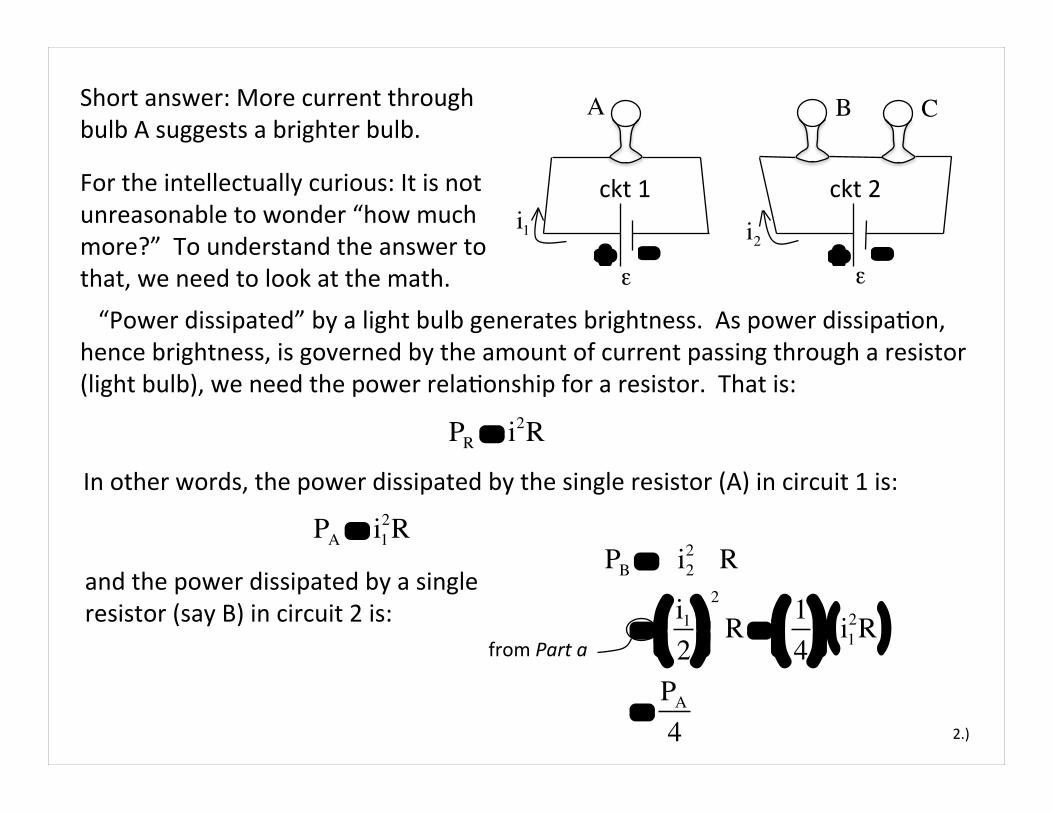
For the intellectually curious: It is not unreasonable to wonder “how much more?” To understand the answer to that, we need to look at the math.
2.)
PR = i2R
In other words, the power dissipated by the single resistor (A) in circuit 1 is:
PA = i12R
and the power dissipated by a single resistor (say B) in circuit 2 is:
PB = i22 R
= i1
2!"#
$%&
2
R =14
!"#
$%&
i12R( )
= PA
4
A B C
+ − + −ε ε
ckt 1 ckt 2 i1 i2
Short answer: More current through bulb A suggests a brighter bulb.
“Power dissipated” by a light bulb generates brightness. As power dissipaCon, hence brightness, is governed by the amount of current passing through a resistor (light bulb), we need the power relaConship for a resistor. That is:
from Part a

Looking at this a li4le differently: The power provided to a circuit by a ba4ery is . Each of our circuits has a ba4ery voltage of . As the current through circuit 2 is half of that through circuit 1, the total power provided to circuit 2 is half that provided to circuit 1. Half of circuit 2’s power, or a quarter of circuit’s 1’s power, is dissipated by each of circuit circuit 2’s two resistors.
3.)
Bo4om line: Bulbs B and C should be a quarter as bright as bulb A.
A B C
+ − + −ε ε
ckt 1 ckt 2 i1 i2
According to the math, the power dissipated by B will be a quarter that dissipated by A, hence B must be a quarter as bright as A.
Pckt−1 = ε i1 and Pckt−2 = ε i2
⇒ Pckt−2
Pckt−1
= ε i2
ε i1
=i2
i1
⇒ Pckt−2
Pckt−1
= i2
i1
=i2
2i2
⇒ Pckt−2 = 12
Pckt−1
P = εiε

Problem 28.17 How much power does each resistor dissipate.
1.)
The equivalent resistance is:
R2 = 2 Ω
Vo = 18 V
Req = R2 + R4 +1
R5
+1
R1
!
"#$
%&
−1
= 2 Ω( ) + 4 Ω( ) + 15 Ω
+1
1 Ω!"#
$%&
−1
= 6.83 Ω
R1 = 1 Ω
R4 = 4 Ω
R5 = 5 Ω
Almost always, we are looking for currents. With those, we can determine:
P = i2R
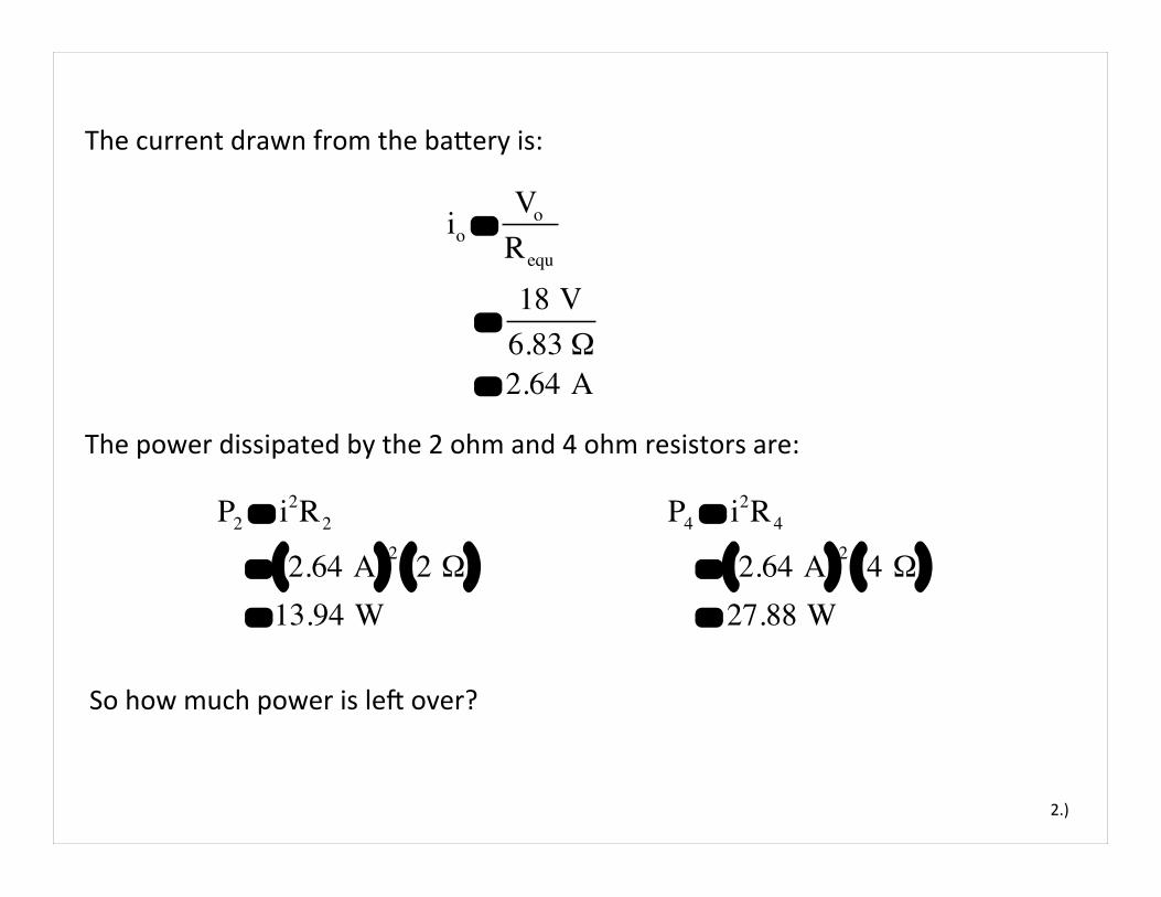
The current drawn from the ba4ery is:
2.)
io =Vo
Requ
= 18 V6.83 Ω
= 2.64 A
P2 = i2R2
= 2.64 A( )2 2 Ω( ) = 13.94 W
The power dissipated by the 2 ohm and 4 ohm resistors are:
P4 = i2R4
= 2.64 A( )2 4 Ω( ) = 27.88 W
So how much power is led over?

The power provided by the ba4ery is:
3.)
Pbattery = ioVo
= 2.64 A( ) 18 V( ) = 47.52 W
The total power dissipated by the 2 ohm and 4 ohm resistors is:
P2 + P4 = 13.94 W( ) + 27.88 W( ) = 41.82 W( )
The two resistors we’ve already taken care of will dissipate 41.82 wa4s. The power supply has provided 47.52 wa4s. That means there is 5.7 wa4s led to accommodate the other two resistors.

Look at the parallel part of the circuit, the current flowing into the parallel combinaCon will be 2.64 amps.
4.)
That means:
R2 = 2 Ω
Vo = 18 V
i5 =16
io =16
2.64 A( )
= .44 A
R1 = 1 Ω
R4 = 4 Ω
R5 = 5 ΩIf the current is broken into six parts, 5 will pass through the 1 ohm resistor and 1 will move through the 5 ohm resistor.
That means the power the 5 ohm resistor dissipates is: P5 = i5
2R5
= .44 A( )2 5 Ω( ) = .968 W

The current through the 1 ohm resistor will be:
5.)
R2 = 2 Ω
Vo = 18 Vi1 =
56
io =56
2.64 A( )
= 2.2 A R1 = 1 Ω
R4 = 4 Ω
R5 = 5 Ω
As expected, the sum of those power quanCCes is 4.84 wa4s +.968 wa4s = 5.8 wa4s. Give or take round-‐off error, this is the amount of power we expected would be available to these two resistors.
That means the power the 1 ohm resistor dissipates is:
P1 = i12R1
= 2.2 A( )2 1 Ω( ) = 4.84 W

Problem 28.21 The circuit is run for 120 seconds.
1.)
R1 = 8 Ω
V1 = 4 V
R3 = 1 Ωa.) What’s the current in each resistor?
R5 = 1 ΩR2 = 5 Ω
V2 = 12 V
R4 = 3 Ω
Below is an enlarged circuit with currents defined on a best-‐guess basis (more about current definiCons at the end of the problem):
R1 = 8 Ω
V1 = 4 V
R3 = 1 Ω
R5 = 1 ΩR2 = 5 Ω
V2 = 12 V
R4 = 3 Ω
i1i2
i1 + i2

2.)
a.) What’s the current in each resistor?
R1 = 8 Ω
V1 = 4 V
R3 = 1 Ω
R5 = 1 ΩR2 = 5 Ω
V2 = 12 V
R4 = 3 Ω
i1i2
i1 + i2
L1
L2
V1 − i2R3 − i2R2 − i1 + i2( )R1 = 04 − i2 1( ) − i2 5( ) − i1 8( ) − i2 8( ) = 0 ⇒ 8i1 + i2 14( ) = 4
⇒ i1 =−14i2 + 4
8 ⇒ i1 = −1.75i2 + .5
The node equa5on was used to define the current through the 8 ohm resistor, so with only two unknowns, we need to use loop equa5ons to finish the task. I’ve idenCfied the loops and direcCon of transverse on the sketch.
L1 : V1 − i2R3 − i2R2 + i1R4 + i1R5 − V2 = 04 − i2 1( ) − i2 5( ) + i1 3( ) + i1 1( ) − 12 = 0 ⇒ − i2 6( ) + i1 4( ) = 8 ⇒ 4i1 − 6i2 = 8 ⇒ 4 −1.75i2 + .5( ) − 6i2 = 8 ⇒ − 7i2 + 2 − 6i2 = 8 ⇒ i2 = −.46
L2 :
(Note that there are several ways to solve these. I’ve used an algebraic approach instead of a matrix-‐driven calculator approach. Either will do!)

3.)
So:
R1 = 8 Ω
V1 = 4 V
R3 = 1 Ω
R5 = 1 ΩR2 = 5 Ω
V2 = 12 V
R4 = 3 Ω
i1i2
i1 + i2
L1
L2
i1 = −1.75i2 + .5 = −1.75 −.46( ) + .5 = 1.3 A
i3 = i1 + i2
= 1.3 + −.46( ) = .84 A
and the current through the 8 ohm resistor is:
Note that the negaCve sign for means that the current is really in the opposite direcCon as defined. This is why assumpCons about current direcCon is not important. Apparently, the 12 volts ba4ery is large enough to sCfle the effects of the 4 volt ba4ery making the current through that branch opposite the direcCon you would expect if the 4 volt ba4ery stood alone. When a “bad” assumpCon is made, though, nothing is hurt. It just means that when you solve for that variable, you will find a negaCve sign in front of its numeric value. No bid deal!
i2

PV1=
Wbattery1
Δt ⇒ Wbattery1 = PΔt
= −1.84 joulessec( ) 120 sec( )
= −222 joules
b.) The energy delivered by each ba4ery makes use of the power relaConship. For :
4.)
V1PV1
= i2V1
= −.46 A( ) 4 V( ) = −1.84 W
R1 = 8 Ω
V1 = 4 V
R3 = 1 Ω
R5 = 1 ΩR2 = 5 Ω
V2 = 12 V
R4 = 3 Ω
(−.46A)
L1
L2
(.84A)
(1.3A)
Why the negaCve sign? The 12 volt ba4ery is forcing current into the 4 volt ba4ery. This is opposite what ba4ery usually do (they are designed to put energy into the system). As such, the ba4ery in this case can be thought of as depleCng energy, suggests a negaCve power raCng. Knowing the power, we can write:
i1i2
i3

b.) The energy delivered by each ba4ery makes use of the power relaConship. For :
5.)
V2
R1 = 8 Ω
V1 = 4 V
R3 = 1 Ω
R5 = 1 ΩR2 = 5 Ω
V2 = 12 V
R4 = 3 Ω
L1
L2PV2= i1V2
= 1.3 A( ) 12 V( )
= 15.6 Watts =Wbattery2
Δt ⇒ Wbattery2 = PV2
Δt
= 15.6 joulessec( ) 120 sec( )
= 1872 joules
(−.46A)
(.84A)
(1.3A)i1
i2
i3

6.)
R1 = 8 Ω
V1 = 4 V
R3 = 1 Ω
R5 = 1 ΩR2 = 5 Ω
V2 = 12 V
R4 = 3 Ω
L1
L2
c.) The energy delivered to the resistors is the same as the energy dissipated by them, so using the power relaConship for resistors, we can write:
PR1= i3
2R1
= .84 A( )2 8 Ω( )
= 5.65 joulessec
As PR1=
Wresistor1
Δt ⇒ Wresistor1 = PR1
Δt
= 5.6 joulessec( ) 120 sec( )
= 672 joules
(−.46A)
(.84A)
(1.3A)i1
i2
i3
Note that the actual soluCon manual lists this as 687 joules because they used .846 amps as their current.

7.)
R1 = 8 Ω
V1 = 4 V
R3 = 1 Ω
R5 = 1 ΩR2 = 5 Ω
V2 = 12 V
R4 = 3 Ω
L1
L2
For :
PR2= i2
2R2
= −.46 A( )2 5 Ω( )
= 1.06 joulessec
As PR2=
Wresistor2
Δt ⇒ Wresistor2 = PR2
Δt
= 1.06 joulessec( ) 120 sec( )
= 127 joules
(−.46A)
(.84A)
(1.3A)i1
i2
i3
Note that the actual soluCon manual lists this as 128 joules as they use -‐.462 amps.
R2
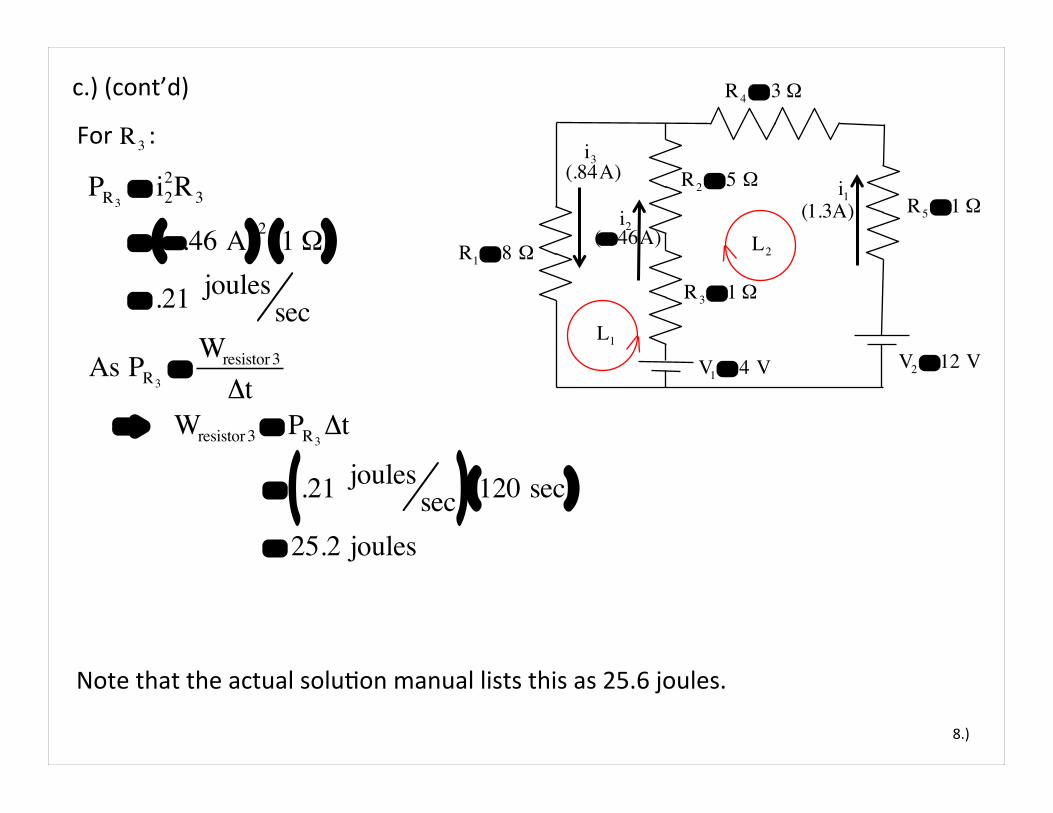
c.) (cont’d)
8.)
R1 = 8 Ω
V1 = 4 V
R3 = 1 Ω
R5 = 1 ΩR2 = 5 Ω
V2 = 12 V
R4 = 3 Ω
L1
L2
For :
PR3= i2
2R3
= −.46 A( )2 1 Ω( )
= .21 joulessec
As PR3=
Wresistor 3
Δt ⇒ Wresistor 3 = PR3
Δt
= .21 joulessec( ) 120 sec( )
= 25.2 joules
(−.46A)
(.84A)
(1.3A)i1
i2
i3
Note that the actual soluCon manual lists this as 25.6 joules.
R3
c.) (cont’d)

9.)
R1 = 8 Ω
V1 = 4 V
R3 = 1 Ω
R5 = 1 ΩR2 = 5 Ω
V2 = 12 V
R4 = 3 Ω
L1
L2
For :
PR4= i1
2R4
= 1.3 A( )2 3 Ω( )
= 5.07 joulessec
As PR4=
Wresistor 4
Δt ⇒ Wresistor 4 = PR4
Δt
= 5.07 joulessec( ) 120 sec( )
= 609 joules
(−.46A)
(.84A)
(1.3A)i1
i2
i3
Note that the actual soluCon manual lists this as 616 joules as they use 1.31 amps.
R4
c.) (cont’d)

10.)
R1 = 8 Ω
V1 = 4 V
R3 = 1 Ω
R5 = 1 ΩR2 = 5 Ω
V2 = 12 V
R4 = 3 Ω
L1
L2
For :
PR5= i1
2R5
= 1.3 A( )2 Ω( )
= 1.69 joulessec
As PR5=
Wresistor5
Δt ⇒ Wresistor5 = PR5
Δt
= 1.69 joulessec( ) 120 sec( )
= 203 joules
(−.46A)
(.84A)
(1.3A)i1
i2
i3
Note that the actual soluCon manual lists this as 205 joules.
R5
c.) (cont’d)

11.)
R1 = 8 Ω
V1 = 4 V
R3 = 1 Ω
R5 = 1 ΩR2 = 5 Ω
V2 = 12 V
R4 = 3 Ω
L1
L2
Using the work/energy values provided by the book (for accuracy sake), the sum of all the energy dissipated by the resistors is:
(−.46A)
(.84A)
(1.3A)i1
i2
i3
d.)
Wdonebyresistors = 687 + 128 + 25.6 + + 616 + 205 = 1661.6 joules
The chemical energy conversion in ba4ery provided 1880 joules (according to the book). So what
V1
happened to the approximately 220 joules of “led-‐over” energy provided by that ba4ery? It went into charging up ba4ery to the tune of -‐222 joules (this is the approximate overlay—the disparity is due to round-‐off error).
V2
e.) The total energy dissipated by the resistors is, as stated above, 1661.6 joules (approximately). This matches (again, as was stated above) the amount of energy (net) put into the system by the ba4eries.

Problem 28.24
1.)
a.) In Parts a and b, we are looking for currents. That means we will be using Kirchoff’s Laws. Unfortunately, the problem is a bit obscure in the sense that I’ve always assumed a dead ba4ery was one in which the voltage across the leads had gone to zero. That would make the sketch misleading. Instead (it finally dawned on me), they want you to
1 Ω
12 V
1 Ω
12 V
.06Ω
Live ba4ery
Dead ba4ery
starter
i1 i2
i3
nodeA
assume the deadness is modeled by the high resistance to charge flow in the branch of the circuit that has the dead ba4ery. Even an “approximately zero-‐volts” model would suggest that the live ba4ery would force current into the dead ba4ery, charging it. I’ve made that assumpCon in defining the current in the dead-‐ba4ery branch. Fortunately, if I’ve goofed, the math will cover me by giving me a negaCve sign in front of any errantly defined currents. Let’s hear it for “the math!”

2.)
a.) We are going to be using Kirchoff’s Laws to solve for all of the currents, so even though this quesCons asks only for the current through the starter, I’m going to write out all the Kirchoff equaCons starCng with a node equaCon for node A. Doing so yields:
1 Ω
12 V
1 Ω
12 V
.06Ω
Live ba4ery
Dead ba4ery
starter
L1
L2
nodeA
L1 : Vlivebattery − i1R1 − i3R3 = 0
i1 i2 i3
For the loops shown:
L2 : Vdeadbattery + i2R2 − i3R3 = 0
With numbers:
L1: 12 V( ) − i1 .01 Ω( ) − i3 .06 Ω( ) = 0 (equation B)
L2 : 12 V( ) + i2 1 Ω( ) − i3 .06 Ω( ) = 0 (equation C)
i1 + i2 = i3 (equation A)

3.)
Solving EquaCons A, B and C simultaneously, we find that the current provided to the starter motor is 172 amps.
1 Ω
12 V
1 Ω
12 V
.06Ω
Live ba4ery
Dead ba4ery
starter
L1
L2
nodeA
i1 i2 i3
b.) From the soluCons alluded to above, the dead-‐ba4ery’s current solves to -‐1.7 volts. As I discussed on the previous page, the negaCve sign simply means that current through the dead-‐ba4ery branch is not downward but, rather, upward.
c.) Apparently, the dead ba4ery isn’t completely dead but is, rather, providing a small trickle of charge (small in comparison to that provided by the live-‐ba4ery) moCvaCng the starter to turn.

Looking at what we have, the Node equaCon for node “a” is:
Problem 28.27
1.)
Assuming and , what is the direcCon and magnitude of current between Points “a” and “e?”
R
ε4R
i1 5R
2R
2ε
a e
b dcε = 250 voltsR = 1 kΩ
I’ve assumed current direcCons and labeled them on the sketch.
i2
i3i4i
i4 = i1 + i (equation A)
Apparently, we can determine “i” if we can determine the other two currents. It isn’t always useful, but someCmes it makes sense to re-‐draw a circuit puqng it into a geometry that is more familiar. That is what I’ve done to the right. (If you can’t see that the two circuits are essenCally the same, talk to someone about it!)
R
εi1
5R
2R
2ε
a e
b dc
i2
i3i4 i3
i1+i2
i1+i2
4R

With both start at “a’ ” and traverse as shown, the Loop EquaCons yield:
2.)
With that, the circuit can be drawn as shown to the right.
R
εi1
2R
2ε
a ' e
b dc
i2i1+i21.71R
The equivalent resistance of the internal parallel combinaCon is:
Requ =1
4R+
15R
!"#
$%&
−1
= 1.71R L1 L2
L1: ε − i1R − i1 + i2( ) 1.71R( ) = 0
L2 : i1 + i2( ) 1.71R( ) + i2 2R( ) − 2ε = 0
Solving these simultaneously yields: i1 = 10x10
−3A
(If I have Cme, I’ll come back and actually do the solving at the end of the problem . . . for those of you who don’t like algebra or matrix manipulaCon):
i2 = 1.3x10⁻¹A

But because the real resistors making up this 1.71R equivalent resistance are in parallel, that voltage must also be the voltage across each of those elements . . . which brings us back to our original circuit.
3.)
So the voltage across that central resistor is:
R
εi1
2R
2ε
a ' e
b dc
i2i1+i21.71R
The current through the 1.71R ohm resistor is:
L1 L2
i1 + i2 = 10x10−3 A( ) + 130x10−3 A( ) = 140x10−3 A
Vc− a ' = i1 + i2( ) 1.71R( ) = 140x10−3 A( ) 1.71 1000 Ω( )( ) = 240 V
R
ε4R
i1 5R
2R
2ε
a e
b dc
i2
i3i4i

And with that informaCon, we can write out that original node equaCon as:
4.)
Knowing the voltage across the 4R resistor is 240 volts, we can write:
Vc− a = i4 4R( )
⇒ i4 =240 V
4 1000 Ω( ) = .06 A
R
ε4R
i1 5R
2R
2ε
a e
b dc
i2
i3i4i
i4 = i1 + i ⇒ i = i4 − i1
= .06 A( ) − .01 A( ) = .05 A
Finally, the calculated value for “i” was posiCve, so we know the originally assumed direcCon was good. Current flows from “a” to “e.”

Problem 28.32
1.)
This a bizarre problem in the sense that it makes you step through all the math, literally by the numbers. I’ve dumped everything we need on the sketch to the right!!
i1
ε3 = 36 V
node A
R1 = 8 Ω
a.) For the circuit shown (and starCng at posiCon “b”), the Loop EquaCon for loop L1 is:
i2
i3
ε2 = 12 V
ε1 = 18 V
R2 = 5 Ω
R5 = 5 Ω
R3 = 11 Ω R4 = 7 Ω
L1
L2
L1: − ε1 + i1R2 + i2R4 − ε2 + i2R3 + i1R1 = 0 − 18 + 5i1 + 7i2 − 12 + 11i2 + 8i1 = 0 ⇒ 13i1 + 18i2 = 30
L2 : − i2R3 + ε2 − i2R4 − ε3 + i3R5 = 0 − 11i2 + 12 − 7i2 − 36 + 5i3 = 0 ⇒ − 18i2 + 5i3 = 24
b.) For the circuit shown (starCng at “c”), the Loop EquaCon for loop L2 is:
b
c
2.)
i1
ε3 = 36 V
node A
R1 = 8 Ω
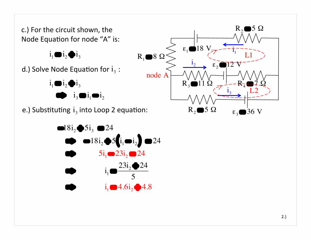
c.) For the circuit shown, the Node EquaCon for node “A” is:
i2
i3
ε2 = 12 V
ε1 = 18 V
R2 = 5 Ω
R2 = 5 Ω
R3 = 11 Ω R4 = 7 Ω
L1
L2
i1 = i2 + i3d.) Solve Node EquaCon for :
e.) SubsCtuCng into Loop 2 equaCon:
i3i1 = i2 + i3
⇒ i3 = i1 − i2
i3
−18i2 + 5i3 = 24 ⇒ − 18i2 + 5 i1 − i2( ) = 24 ⇒ 5i1 − 23i2 = 24
⇒ i1 =23i2 + 24
5 ⇒ i1 = 4.6i2 + 4.8

3.)
i1
ε3 = 36 V
node A
R1 = 8 Ωi2
i3
ε2 = 12 V
ε1 = 18 V
R2 = 5 Ω
R2 = 5 Ω
R3 = 11 Ω R4 = 7 Ω
L1
L2
f.) Solving the modified loop equaCons for and , we get:
13 i1 + 18i2 = 3013 4.6i2 + 4.8( ) + 18i2 = 30⇒ 59.8i2 + 62.4 + 18i2 = 30 ⇒ 77.8i2 + 62.4 = 30 ⇒ 77.8i2 = −32.4 ⇒ i2 = −.416 A
i1i2i1 = 4.6i2 + 4.8Using :
This means:
13i1 + 18 i2 = 3013i1 + 18 −.416 A( ) = 30 ⇒ i1 = 2.88 A
4.)
i1
ε3 = 36 V
node A
R1 = 8 Ωi2
i3
ε2 = 12 V
ε1 = 18 V
R2 = 5 Ω
R2 = 5 Ω
R3 = 11 Ω R4 = 7 Ω
L1
L2
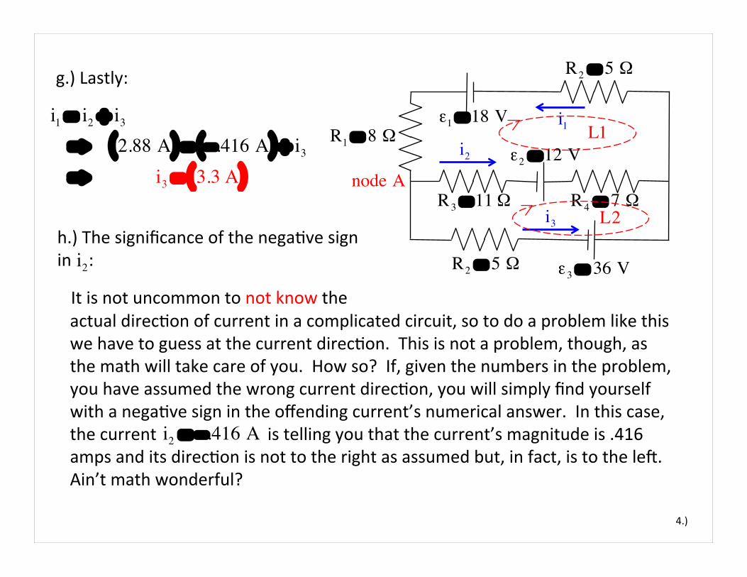
g.) Lastly:
i1 = i2 + i3
⇒ 2.88 A( ) = −.416 A( ) + i3
⇒ i3 = 3.3 A( )
h.) The significance of the negaCve sign in : i2
It is not uncommon to not know the actual direcCon of current in a complicated circuit, so to do a problem like this we have to guess at the current direcCon. This is not a problem, though, as the math will take care of you. How so? If, given the numbers in the problem, you have assumed the wrong current direcCon, you will simply find yourself with a negaCve sign in the offending current’s numerical answer. In this case, the current is telling you that the current’s magnitude is .416 amps and its direcCon is not to the right as assumed but, in fact, is to the led. Ain’t math wonderful?
i2 = −.416 A

Problem 28.34
1.)
a.) Time constant: ε = 30 V
S
τ = RC
= 1x10⁶ Ω( ) 5x10⁻⁶ f( ) = 5 seconds
C
+−
C = 5x10⁻⁶ fR = 1x10⁶ Ω
Qmax = Cε
= 5x10⁻⁶ f( ) 30 V( ) = 150x10−6 coulombs
RThe circuit’s parameters are ,
b.) Once the capacitor is completely charged, no current will flow through the circuit and all of the ba4ery’s voltage drop will be across the capacitor. In that case, we can write:
and ε = 30 V.

2.)
c.) There are two ways to do this. The first is to use the current funcCon we’ve derived:
ε = 30 V
S
i(t) = ioe− t /RC
= ε
Re− t /RC
=30 V( )
1x10⁶ Ω( )e− t / 1x10⁶ Ω( ) 5x10⁻⁶ f( )
= 30x10−6 A( )e− t /5
+−
C = 5x10⁻⁶ f
R = 1x10⁶ Ω
R
EvaluaCng this for t = 10 seconds yields:
i = 30x10−6 A( )e−10 /5
= 4.06x10⁻⁶ A

3.)
The second way: Two Cme constants is the amount of Cme it takes for the current to drop to approximately 13.5% of its iniCal value. In Part “a,” we determine that the Cme constant was 5 seconds. That means 10 seconds is two Cme constants worth, which means our current value at that point should be:
ε = 30 V
S
i(2τ) = .135( ) io
= .135( ) εR
= .135( ) 30 V( )1x10⁶ Ω( )
= 4.05x10⁻⁶ A
C
+−
R
The slight deviaCon between the two values is due to round-‐off error.

Problem 28.37
1.)
8 Ωa.) Voltage difference across capacitor?
ε = 10 V
We know the electrical potenCal of Point “a” is 10 volts (it’s connected to the high side of the ba4ery). If we can determine the voltage drop
1 µf+
−
2 Ω
1 Ω
4 Ω
a
b c This is fun! When fully charged, there is no current through the capacitor. That means the circuit could be re-‐drawn as shown below.
8 Ω
ε = 10 V+
−
2 Ω
1 Ω
4 Ω
a
b c
Vac
across the 1 ohm resistor, we can determine the electrical potenCal at Point “b” (it’ll be 10 -‐ ). Doing a similar process on the other side and we have what we need to determine the voltage across b-‐c, which will be the voltage across the cap.
To that end:
ΔVa−b

2.)
With the cap out of commission, there are 10 volts across Points “a” and “d.” That means we can write:
i110 V = i1( ) 1 Ω + 4 Ω( ) ⇒ i1 = 2 A
That means the electrical potenCal at Point “b” is:
a
R2 = 8 Ω
ε = 10 V+
−
2 Ω
R1 = 1 Ω
4 Ω
b c
d ΔVa−b = i1R1
= 2 A( ) 1 Ω( ) = 2 V
With , we can write: i1
Vb = Va − Vdrop
= 10 V( ) − 2 V( ) ⇒ Vb = 8 A

3.)
Similarly for the right secCon of resistors, we can write:
i110 V = i2( ) 8 Ω + 2 Ω( ) ⇒ i2 = 1 A
That means the electrical potenCal at Point “c” is:
a
R2 = 8 Ω
ε = 10 V+
−
2 Ω
R1 = 1 Ω
4 Ω
b c
d
ΔVa− c = i2R2
= 1 A( ) 8 Ω( ) = 8 V
With , we can write: i2
Vc = Va − Vdrop
= 10 V( ) − 8 V( ) ⇒ Vc = 2 A

4.)
Apparently, the net voltage drop between Points “b” and “c” is:
i1
a
R2 = 8 Ω
ε = 10 V+
−
2 Ω
R1 = 1 Ω
4 Ω
b c
d
(as the voltage across a capacitor is always defined as posiCve)
Vb− c = Vc − Vb
= 2 V( ) − 8 V( ) ⇒ Vcap = 6 V
b.) With the ba4ery disconnected, the circuit becomes as shown to the right. If we combine the resistor in parallel, we get an equivalent resistance of:
R =1
9 Ω+
16 Ω
"
#$%
&'
−1
= 3.6 Ω
9 Ω
10 Ω
1 µf

5.)
So our circuit is now as shown to the right. The Cme constant for that circuit is:
The voltage across the capacitor will be the same as the voltage across the resistor. As the voltage across the resistor is a funcCon of the current through it, and as the current is governed by the relaConship:
τ = RC
= 3.6 Ω( ) 1x10⁻⁶ f( ) = 3.6x10⁻⁶ seconds
3.6 Ω
1 µf
e− t /RC
The amount of Cme required for that factor to drop to 1/10 is:
e− t /RC =1
10
⇒ ln e− t /RC( ) = ln 110#$%
&'(
⇒ − t / RC = ln 110#$%
&'(
⇒ t = −RCln 110#$%
&'(
= − 3.6 Ω( ) 10−6 f( ) −2.3( ) = 8.28x10⁻⁶ seconds

As expected, this is a li4le shy of the value of that we calculated.
6.)
Note: Remember that ader two Cme constants, the current will drop to 13.5% of the maximum current and voltage (just a hint above our 10% mark). Twice our Cme constant in this instance is:
8.28x10⁻⁶ seconds
2τ = 2RC
= 2 3.6x10⁻⁶ seconds( ) = 7.2x10⁻⁶ seconds
Problem 28.39
1.)
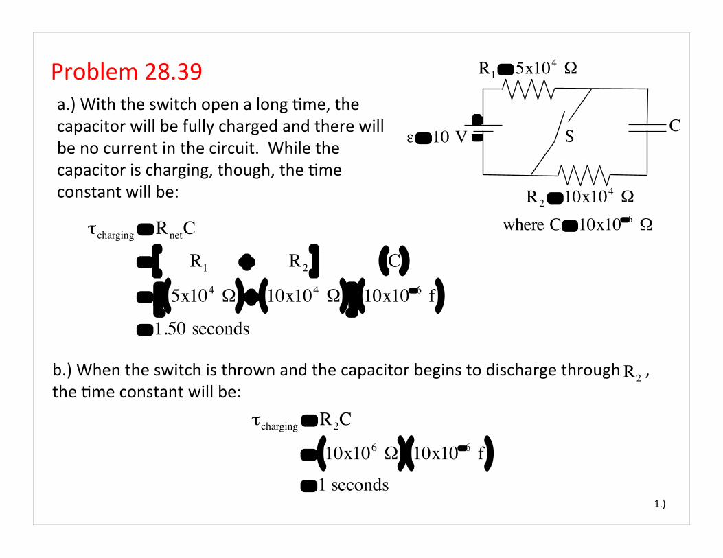
a.) With the switch open a long Cme, the capacitor will be fully charged and there will be no current in the circuit. While the capacitor is charging, though, the Cme constant will be:
ε = 10 V S
τcharging = RnetC
= R1 + R2[ ] C( )
= 5x10⁴ Ω( ) + 10x104 Ω( )#$ %& 10x10−6 f( ) = 1.50 seconds
b.) When the switch is thrown and the capacitor begins to discharge through , the Cme constant will be:
C+−
where C = 10x10−6 Ω
R1 = 5x10⁴ Ω
R2 = 10x104 Ω
R2
τcharging = R2C
= 10x106 Ω( ) 10x10−6 f( ) = 1 seconds

2.)
c.) This is where things get interesCng. As was said above, with the switch opened for a long Cme, the current goes to zero as the capacitor charges to its maximum, and the voltage across the capacitor at that point is . When the switch it thrown, then, a current will be generated through due to the
i1ε1 = 10 V
ba4ery and a current will be generated through due to the voltage across the capacitor. All of these currents are shown in the sketch.
C+−
R1 = 5x10⁴ Ω
R2 = 10x104 Ω
R1
ε1 − i1R1 = 0
⇒ i1 =ε1
R1
⇒ i1 =10 V( )
5x10⁴ Ω( ) ⇒ = 2x10⁻⁴ A
ε = 10 V
R2
+
−
i2i1 + i2
From Ohm’s Law on the led loop, we can write:
where C = 10x10−6 Ω

3.)
Remembering that , Ohm’s Law used on the right loop yields:
i1ε1 = 10 V
Coupling those two bits of informaCon allows us to write:
C+−
C = 10x10−6 ΩR1 = 5x10⁴ Ω
R2 = 10x104 Ω
q(t)C
− i2R2 = 0
⇒ i2 =1
R2C#
$%&
'(q(t)
+
−
i2i1 + i2
We know from the definiCon of capacitance that:
q(t) = Qmaxe− t /R2C
C = QmaxVmax
⇒ Qmax = CVmax
q(t) = Qmaxe− t /R2C
= CVmaxe− t /R2C
where C = 10x10−6 Ω
Vcap =q(t)C
and we know from previous experience that the charge on a discharging capacitor is equal to:

4.)
With that, we can write:
i1ε1 = 10 V C+
−
C = 10x10−6 ΩR1 = 5x10⁴ Ω
R2 = 10x104 Ω
i2 =1
R2C!
"#$
%&q(t)
= 1R2C
!
"#$
%&CVmaxe
− t /R2C( )
= 1R2
!
"#$
%&Vmaxe
− t /R2C( )
= 110x104 Ω!"#
$%&
10 V( )e− t / 10x104( ) 10x10−6( )( ) = 10−4( )e− t / 1 sec( )
+
−
i2i1 + i2
That means the switch carries a downward current of:
i1 + i2 = 2x10⁻⁴ A( ) + 1x10⁻⁴( )e− t / 1 sec( ) A"# $%
where C = 10x10−6 Ω
Crazy, huh?