problem management: a system engineering management
TRANSCRIPT

Problem Management: A System Engineering Management Framework
By Bill A. Olson
B.S. in Electronics, February 1984, Chapman University M.S. in Program Management, December 2004, Florida Institute of Technology
A Dissertation submitted to
The Faculty of The School of Engineering and Applied Science
of The George Washington University in partial satisfaction of the requirements for the degree of
Doctor of Philosophy
January 31, 2012
Dissertation directed by
Thomas Andrew Mazzuchi Professor of Operations Research and of Engineering Management
Shahram Sarkani
Professor of Engineering Management and Systems Engineering

ii
The School of Engineering and Applied Science of The George Washington University
certifies that Bill Allen Olson has passed the Final Examination for the degree of Doctor
of Philosophy as of 30 December 2011. This is the final and approved form of the
dissertation.
Problem Management: A System Engineering Management Framework
Bill Allen Olson
Dissertation Research Committee:
Thomas Andrew Mazzuchi, Professor of Operations Research and of Engineering Management, Dissertation Co-Director
Shahram Sarkani, Professor of Engineering Management and Systems Engineering, Dissertation Co-Director
Lile Murphree, Jr., Professor of Engineering Management, Chair Person of the Examination Committee
Michael Stankosky, Professor of Engineering Management and Systems Engineering, Committee Member
Timothy Eveleigh, Adjunct Professor of Systems Engineering, Committee Member

iii
Acknowledgements
I am grateful to Dr. Thomas A. Mazzuchi and Dr. Shahram Sarkani, Professors of
Engineering Management and Systems Engineering at the George Washington
University, and to Dr. Kevin Forsberg, Chief Executive Officer and cofounder of the
Center for Systems Management, for supporting me in the development of a problem
management framework and for their insights and guidance throughout the development
and completion of this dissertation.
To my fellow classmates in my PHD cohort, I thank them for their help,
encouragement, and friendship during the course of the program.
I am thankful to Mr. Kevin Topp, Systems Engineering Manager at Huntington
Ingalls Newport News Shipbuilding and adjunct Professor of Engineering Management
and Systems Engineering at the George Washington University, for his insightful
comments and support. I would like to thank Ms. Johanna Lunglhofer Granor for her
amazing technical editing skills and making sure all of my commas are in the right place.
Most of all I would like to thank my loving wife Sheila. She has stood beside me
and believed in me when it seemed that I would never succeed. “Sheila I love you”
Finally, I must recognize my parents, Orville N. Olson, Dorothy Olson and Jean
Olson, who have instilled in me the importance of education and desire to pursue goals
that can only be achieved through hard work. Although my dad is no longer with us,
through faith, I find comfort in knowing that they both also share in the joy of this
accomplishment.

iv
Abstract
Problem Management: A System Engineering Management Framework
Problem management is not recognized as a system engineering process. Unlike risk
management where risks could impact a project at some future date, problems impact the
project now. Therefore, a robust problem management process should be established
(similar to the risk management process described in chapter five of the INCOSE
handbook) [1], early in a project’s formulation. The process should be continuous
throughout all phases of the project life cycle and should be included as a part of the
project System Engineering Management Plan. The process should at a minimum
address: problem identification, problem assessment, problem root cause investigation,
and problem corrective action planning and reporting. It should also include a roll-up of
all current problems, problem closure, and the development of a strong interface with the
project’s knowledge management system.
This paper proposes a problem management systems engineering framework, based
on the foundations of risk, opportunity management and knowledge management, which
could be used by corporations, government agencies, and programs to establish a robust
problem management process for use on their projects.
v
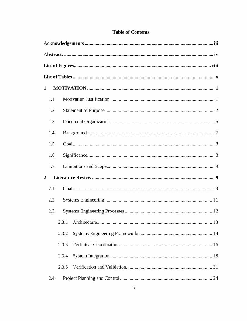
Table of Contents
Acknowledgements .......................................................................................................... iii
Abstract…. ........................................................................................................................ iv
List of Figures ................................................................................................................. viii
List of Tables ..................................................................................................................... x
1 MOTIVATION ......................................................................................................... 1
1.1 Motivation Justification ...................................................................................... 1
1.2 Statement of Purpose .......................................................................................... 2
1.3 Document Organization ...................................................................................... 5
1.4 Background ......................................................................................................... 7
1.5 Goal ..................................................................................................................... 8
1.6 Significance......................................................................................................... 8
1.7 Limitations and Scope......................................................................................... 9
2 Literature Review ..................................................................................................... 9
2.1 Goal ..................................................................................................................... 9
2.2 Systems Engineering ......................................................................................... 11
2.3 Systems Engineering Processes ........................................................................ 12
2.3.1 Architecture ............................................................................................... 13
2.3.2 Systems Engineering Frameworks ............................................................ 14
2.3.3 Technical Coordination ............................................................................. 16
2.3.4 System Integration .................................................................................... 18
2.3.5 Verification and Validation ....................................................................... 21
2.4 Project Planning and Control ............................................................................ 24

vi
2.4.1 Project Planning ........................................................................................ 25
2.4.2 Financial Contract Management ............................................................... 27
2.4.3 Schedule Management .............................................................................. 29
2.5 Overlapping Processes ...................................................................................... 32
2.5.1 Risk Management ..................................................................................... 33
2.5.2 Opportunity Management ......................................................................... 37
2.5.3 Task Definition ......................................................................................... 38
2.5.4 Knowledge Management .......................................................................... 40
2.5.5 Information Management .......................................................................... 44
2.5.6 Configuration Management ...................................................................... 45
2.5.7 Technical Performance Management ....................................................... 49
2.6 Additional other significant processes .............................................................. 50
2.6.1 Decision Management Process ................................................................. 51
2.6.2 Cost Benefit Analysis ............................................................................... 53
2.6.3 Earned Value Management ....................................................................... 54
2.7 Literature Conclusion........................................................................................ 55
3 Problem Management ............................................................................................ 56
3.1 Problem Management ....................................................................................... 56
3.1.1 Overview ................................................................................................... 56
3.2 Problem Management Framework .................................................................... 69
3.2.1 Problem Planning - Step 1 ........................................................................ 70
3.2.2 Problem Identification - Step 2 ................................................................. 73
3.2.3 Problem Analysis and Assessment - Step 3 .............................................. 75

vii
3.2.4 Problem Handling - Step 4 ........................................................................ 78
3.2.5 Problem Monitoring - Step 5 .................................................................... 81
3.2.6 Problem Closure - Step 6 .......................................................................... 83
3.2.7 Problem Knowledge Management – Step 7 .............................................. 84
4 Recommendations and Conclusions ...................................................................... 85
4.1 Recommendation .............................................................................................. 85
4.1.1 Purpose ...................................................................................................... 86
4.1.2 Description ................................................................................................ 86
4.1.3 Outputs from Activities............................................................................. 89
4.1.4 Process Activities ...................................................................................... 90
4.2 Conclusions ....................................................................................................... 94
5 Recommendation for Future Research ................................................................. 95
5.1.1 Opportunity Management Framework ...................................................... 95
5.1.2 Problem, Risk, Opportunity, Realized Opportunities, and Earned Value
Management Integration ........................................................................................... 96
5.1.3 Total Systems Engineering Framework .................................................... 96
6 BIBLIOGRAPHY ................................................................................................... 98

viii
List of Figures
Figure 1-1: Systems Engineering Management Processes Optimal Process Integration
Venn diagram ...................................................................................................................... 7
Figure 2-1: Integrated Academic and Literature Review Roadmap ................................ 10
Figure 2-2: System Architecture Goal[11] ...................................................................... 14
Figure 2-3: Systems engineering and management process model with integration
interface[16]. ..................................................................................................................... 19
Figure 2-4: INCOSE Systems Engineering Vee Model[20] ............................................ 23
Figure 2-5: Typical Project Planning Steps ...................................................................... 26
Figure 2-6: Comparison of Life Cycle Models[1] ............................................................ 31
Figure 2-7: Common Risk Management Process Functions ............................................. 35
Figure 2-8: Common Opportunity Management Functions .............................................. 37
Figure: 2-9: Six Critical Task Definition Requirement Questions .................................. 39
Figure 2-10: Basic Configuration Management Process Steps ........................................ 46
Figure 2-11: Decision Tree for a Bid-No Bid decision[1] ................................................ 52
Figure 3-1: NASA Problem Management Matrix[4] ....................................................... 60
Figure 3-2: Opportunity, Risk, and Problem Management Matrices[2] .......................... 61
Figure 3-3: Five Categories of problems[2] ..................................................................... 63
Figure 3-4: Toyota Stock Price vs. Time[2] .................................................................... 66
Figure 3-5: Problem Management Framework[2] ........................................................... 69
Figure 3-6: Problem Management Framework Step 1 ..................................................... 71
Figure 3-7: Problem Management Framework Step 2 ..................................................... 74
Figure 3-8: Problem Management Framework Step 3 ..................................................... 77

ix
Figure 3-9: Problem Management Framework Step 4 ..................................................... 80
Figure 3-10: Problem Management Framework Step 5 ................................................... 82
Figure 3-11: Problem Management Framework Step 6 ................................................... 84
Figure 3-12: Problem Knowledge Management Process Step 7 ..................................... 85
Figure 4-1: Context Diagram for the Problem Management Process Inputs to Activitie . 88

x
List of Tables
Table 1-1: Systems Engineering/Project Planning and Control Overlap ........................... 6
Table 2-1: Systems Engineering Centric Processes Reviewed in Section 2.3. ................ 12
Table 2-2: Three Common Systems Architecture Frameworks ...................................... 16
Table 2-3: Partial List of Systems Engineering Sub-specialties, Tasks, and Titles ......... 18
Table 2-4: Two examples of problems identified during systems integration ................. 20
Table 2-5: Project Planning Processes Reviewed in Section 2.4. .................................... 25
Table 2-6: Financial Contract Management Software Solutions ..................................... 28
Table 2-7: Project Planning Processes Reviewed in Section 2.5 ..................................... 32
Table 2-8: Alternative Definitions of Risk Management and Risk ................................. 34
Table 2-9: Partial List of Commercial Knowledge Management Software .................... 43
Table 3-1: Sample List of Citations from the INCOSE handbook[1] ............................. 57

1
1 MOTIVATION
1.1 Motivation Justification
Early in the development of risk management processes, project teams justified a lack
of risk management by using excuses such as:
I don’t have time for what-if’s.
Risk Management costs too much money.
Risk Management is a paperwork nightmare.
I do not want to look bad in front of my boss.
This is a new fad – It will pass and then be back to business as usual.
If I state my risks, I might be the next victim of “shoot the messenger
syndrome.”
All of the above have been proven false, and risk management is a proven,
sustainable, cost-saving process that delivers value to projects. They are not adequate
justifications for failure to manage project problems in an open, consistent manner.
Many risks are realized and closed as problems. This is a justifiable option under
most risk management plans and guidebooks. However, once a risk is closed, what
happens to the new problem?
Currently there is no internationally recognized process to deal with problems. It is
time for problems to come out from behind closed-door meetings, get off of PowerPoint
slides, and become a recognized systems engineering discipline which could significantly
benefit a project. Like risk management, the benefits of establishing robust problem
management processes are substantial. This paper proposes a system engineering-based

2
framework intended to provide the backbone of a problem management process for use
by projects, programs, government, and corporate offices to manage their problems in an
open and consistent manner.
1.2 Statement of Purpose
Problem management is not defined as a systems engineering discipline. Yet, the
word ‘problem’ is mentioned 92 times in the International Council on Systems
Engineering (INCOSE) handbook version 3.2.[1] Most System Engineering processes
use the word ‘problem’ to describe the design space of the systems engineering process.
The INCOSE handbook defines ‘system engineering’ as, “an interdisciplinary
approach and means to enable the realization of successful systems. The systems
engineering process focuses on defining customer needs and required functionality early
in the development cycle, documenting requirements, and then proceeding with design
synthesis and system validation while considering the complete problem: operations, cost
and schedule, performance, training and support, test, manufacturing, and disposal.
Systems engineering considers both the business and the technical needs of all customers
with the goal of providing a quality product that meets the user needs”.[1]
Contrastingly, the systems engineering approach taken by most projects today lacks a
problem management process similar to the risk management process. The purpose of
this paper is to fill this gap in the system engineering process by ensuring that a rigorous
problem management process is in place at the beginning of a project’s life cycle. And
that the systems engineering and Project Management teams have a sound management
process in place which will significantly contribute to project success and to customers’

3
satisfaction knowing that the team is executing to the best of their ability while fully
disclosing and addressing all of the problems and how they impact the project’s bottom
line.
When not developing designs to eliminate problems, project teams spend large sums
of money developing risk management plans with the goal of preventing problems from
occurring. Yet, risks are still realized.
Problem management is different from risk management in the probability of
occurrence. While ‘risks’ are potential problems, which, if not dealt with, may become
problems in the future, ‘problems’ exist in the present and need to be addressed
immediately.
There are two types of problems[2]. Anticipated problems are realized risks which
have a 100% likelihood of occurring. In these cases, the risk was known but the project
was unable to keep the risk from being realized. Unplanned events – sometimes called
issues, non-conformances or anomalies – are unknown or unanticipated problems. For
the purposes of this paper, the word ‘problem’ encompasses both of these descriptions.
What happens when problems occur? Are projects prepared to effectively deal with
problems? There is no standard process available which defines categories of problems,
provides a problem management approach, establishes a problem treatment (handling)
approach, and defines a methodical hierarchical scaling of problems.
The National Aeronautics and Space Administration (NASA) recognized the need for
problem management after the November 2003 Space Shuttle Columbia accident [3].
NASA developed a problem management process similar to the risk process that enables
projects to determine which problems to expend valuable resources on and to status the

4
results of problem resolution efforts.[4] However, the primary focus of the NASA
Management Guidebook is on safety and schedule.
Problem Management is defined as a process to identify, report, analyze, develop
resolution plans, assess impacts, and monitor problems as they are identified. The
Problem Management process systematically searches for problems, directs problems
with a potential for occurrence into the Risk Management process, and processes
problems with 100% occurrence into the Problem Management process.
This problem management system engineering framework is based on the
comprehensive INCOSE risk management process, some of the concepts in the NASA
Problem Management Guidebook [4], and concepts developed during the systematic
literature research conducted in chapter 2. This framework draws upon the lessons
learned in the development of risk management to establish problem identification and
problem resolution techniques which, in turn, establish a foundation for a cradle-to-grave
lifecycle approach to problem management for use by projects to better control cost,
schedule, technical, programmatic, and environmental and safety problems. This end-to-
end approach is based on the recognized assumption that problems are going to occur
during the life cycle of a project.
This paper focuses on establishing a requirement to implement a problem
management framework. To establish the need to develop a contractual requirement for a
project problem management plan at the beginning of a project. Implementing a plan
ensures that when problems are identified they are addressed up front and continuously
during the project’s life cycle to minimize related complexities and challenges later on in
the systems engineering life cycle. This paper provides an overview of problem

5
management and the activities included in the proposed problem management
framework.
1.3 Document Organization
This document is organized to describe a proposed problem management framework
that synthesizes the risk, opportunity, knowledge management, earned value systems, and
other systems engineering processes to develop a problem management system from the
proposed framework.
Chapter 2 (literature review) establishes the foundation that the proposed framework
is built upon. The literature review focuses on the current practices and applications that
make up the core systems engineering project processes, starting with INCOSE
processes, with potential interfaces with a problem management framework. Table 1-1 is
an expansion of the INCOSE Project Processes which depicts the overlap between key
project processes.
The INCOSE handbook does not include several key processes which are critical to
the success of a project. It is proposed that the problem management framework will
fall somewhere in the overlap (blue columns) with a strong bidirectional interface with
the risk management, knowledge management, task definition, opportunity management,
and the customer interaction processes.

6
Table 1-1: Systems Engineering/Project Planning and Control Overlap
Chapter 3 provides an in depth overview of problem management concepts, and then
lays out a detailed description of the problem management framework in the format of
the International Council on Systems Engineering Handbook. Chapter 4 provides the
final recommendation and conclusion. Chapter 5 presents several recommendations for
future research as a result of this research.

7
1.4 Background
Figure 1-1: Systems Engineering Management Processes Optimal Process
Integration Venn diagram
Developing and delivering complex systems requires tight control of all of the
systems engineering management processes. The INCOSE handbook defines most of the
project processes; however the handbook leaves out several key project planning
processes. Figure 1-1 Systems Engineering Management Processes Optimal Process
Integration Venn diagram expands the list to include knowledge and opportunity
management. The center -- optimal spot -- is where problem management should reside.
A problem management process developed from the proposed problem management
framework enlarges the optimal spot making it easier for a project to obtain its goal of
providing the best value to their customers and stakeholders. The project processes are
Optimal Integration ‐where all SE project processes overlap and work effectively together toward success of a project
Risk and Opportunity Process
Project Assessment Process
Decision Process
Project Planning
Knowledge Management
Decision Management Process Planning
Problem Management
Problem Management – The missing piece??

8
used to establish and update plans, to execute, to determine progress toward project goals,
and as controllers of the project through fulfillment. Individual project processes may be
invoked at any time in the life cycle and at any level in a hierarchy of projects, as
required by project plans or unforeseen events. The project processes should all be
instituted with the same rigorous discipline and formality. Seven key projects processes
are: Project Assessment and Control Process, Decision Management Process, Risk
Management Process, Opportunity Management Process, Configuration Management
Process, Information Management Process, Measurement Process, and Knowledge
Management[1].
1.5 Goal
The goal of this research is to develop and present a comprehensive Problem
Management Framework that is used to support the system engineering design processes
by integrating proven systems engineering processes. This framework relies on the
familiar concepts of risk and opportunity management while integrating with the seven
key project processes identified in section 1.4.
1.6 Significance
This research is of particular importance because of the lack of an internationally
recognized problem management framework. A framework must be developed that can
be used to plan, quantify, report, and capture the history of the problems encountered
during the systems engineering design life cycle. There are large sums of money at stake
during the development of complex systems for defense, space, and commercial projects.

9
The implementation of a comprehensive problem management framework at the
beginning of a project could be the difference between project success and failure.
1.7 Limitations and Scope
For the purpose of this research, the scope and analysis are limited to the
“International Council on Systems Engineering (INCOSE) project processes as defined in
the INCOSE handbook”[1] and the Systems and Software engineering – systems life
cycle processes standard ISO/IEC 15288:2008[5].
2 Literature Review
2.1 Goal
“Conducting a literature review is a means of demonstrating an authors’ knowledge
about a particular field of study”[6]. The goal of this literature review is to develop an
integrated view across all of the major systems engineering processes and then to
generalize the findings across the various frameworks, treatments, outcomes and settings
to foster and resolve debate about a comprehensive problem management framework.
The secondary goal is to meld the outcomes across the selected frameworks and
processes and to critically analyze previous research to identify the core concepts which
impact, enhance, or substantiate need for the proposed problem management framework.
Figure 2-1 is an integrated view, road map of the literature and academic steps taken to
ensure that exhaustive research was conducted.

10
Figure 2-1: Integrated Academic and Literature Review Roadmap
The review starts with a definition of systems engineering followed by a review of the
core systems engineering processes (Systems Architecture, Systems Engineering
Frameworks, Technical Coordination, Systems Integration, and Validation and
Verification). This section was followed by a review of the project Planning Processes
(Project Planning, Financial Contract Management, and Schedule Management). The
next step of the review was to review processes which overlap the Systems Engineering
and Project Planning and Control Processes (Risk Management, Opportunity
Management, Task definition, Knowledge Management, Information Management,
Configuration Management, and Technical Performance Management). To ensure all
INCOSE Systems Management Processes
Integration of Concepts
Olson, Mazzuchi, Sarkani, Forsberg (Journal of Systems Engineering: Volume 2, 2012)
Problem Management Definition
HRA-INCOSE Conference (2010)Extending Risk Management to
Problem Management
Presented “Problem Management Process, Filling the Gap in the SystemsEngineering Processes between the Risk and Opportunity Processes
GWU Class Work
Identify and Refine Potential Correlations to Selected Dissertation
Research Topic
EMSE 216 “Research Methods for the Engineering Manager”
EMSE 208 “Stochastic Foundations of Operations Research”
EMSE 288 “Technology Issue Analysis”
EMSE 286 “Architecture Description and Enterprise Architecture”
EMSE 288 “Special Topics: Advanced Systems Engineering”
Goal
Identify and validate a Dissertation Topic through Course work and a
comprehensive literature review
Systems Engineering Historical Review
Engineering Project Management
Systems Engineering Architectures and Frameworks
INCOSE
Review INCOSE Process Validate need for a Problem Management
Framework
Literature Review Systems Engineering Processes
Systems Integration
Validate Problem Management Requirement
INCOSE International Conference (2011) Chair of INCOSE KM and Handbook Committee confirmed need and asks for a chapter in the
next Revision of the Handbook (GWU to Lead the effort)
Is Problem Management
Valid?
Systems Engineering Standards Review
Configuration
Knowledge
Risk
OpportunityDecision
Knowledge Management
Is There a Published
Problem Management Process?
Contract

11
bases are covered the last section of the review addresses other significant processes in
which significant problems are discovered (Decision Management, Cost Benefit
Analysis, and Earned Value Management).
At key points in each subject review, a short discussion on the potential interfaces
with a problem management framework was added to help focus the need for projects to
establish a Problem Management process based on the proposed problem management
framework. The scope of research was narrowed by focusing only on scholarly journals,
reference books, and the INCOSE handbook.
2.2 Systems Engineering
Kossiakoff and Sweet assert that, “The function of systems engineering is to guide the
engineering of complex systems” [7]. INCOSE expands on this point. “Systems
engineering is an interdisciplinary approach and means to enable the realization of
successful systems. It focuses on defining customer needs and required functionality
early in the development cycle, documenting requirements, and then proceeding with
design synthesis and system validation while considering the complete problem:
operations, cost and schedule, performance, training and support, test, manufacturing, and
disposal. Systems Engineering considers both the business and the technical needs of all
customers with the goal of providing a quality product that meets the user needs”[1].
David Hall one of the first pioneers in the field, wrote one of the first definitive books
on systems engineering in 1962 called “A Methodology for Systems Engineering”[8].
Hall was the first of many who saw that a systematic approach to system design
eliminates many problems, saves money and increases the chances of the product being

12
delivered on time. Soon the U.S. military also saw the light and developed Mil-Std 499
and 499A the requirements of which were often included as contractual obligations in
new development projects.
The latest standard ISO/IEC 15288:2008 is a continuation of David Hall’s work. The
ISO standard is the basis of the format and content of the INCOSE Handbook. The best
way to define systems engineering is that it is a problem management system. When a
project is conceived to develop something new, using the systems engineering process is
the best methodology to solve the problem of what, how, when, where, why, how big,
how much cost, et cetera. Table 2-1 highlights the systems engineering centric processes
which are reviewed in the section of the literature review.
2.3 Systems Engineering Processes
Table 2-1: Systems Engineering Centric Processes Reviewed in Section 2.3.
Project ProcessSystems Engineering Over Lapping Processes Project Planning and Control
System Architecture* Risk Management* Task Definition* Project Planning*
Technical Coordination* Customer Interaction*
Opportunity Management
Resource Allocation*
System Integration* Knowledge Management
Configuration Management
Financial Contract Management*
Validation and Verification
Technical Performance Management
Information Management
Schedule Management
* = INCOSE Project Process

13
2.3.1 Architecture
INCOSE describes the Architecture Design Process. “This process encapsulates and
defines the areas of solution expressed as a set of problems of manageable, conceptual
and, ultimately, realizable proportions”[1]. Blanchard and Fabrycky explain that
“Functional analysis is an iterative process of translating system requirements into the
detailed design criteria and subsequent identification of resources required for operation
and support” [9]. Functional analysis is the first of two system engineering processes
used to define the system design. It is here that problem management can initially be
effectively used to identify potential problems before they impact the project. These
potential problems are project risks that should be entered into the project risk register
unless they have a likelihood of occurrence at the time of identification of one[2, 10].
Physical analysis is the next step in which identification of project problems could
occur. Since physical analysis takes place later in the project life cycle, the likelihood
and consequence of a problem impacting the project completion schedule is greater. It is
critical that these steps of the system architecture be used to identify problems. Figure 2-2
“System Architecture Goal”[11], depicts the importance of allocating requirements using
functional and physical analysis/allocation processes.

14
Figure 2-2: System Architecture Goal[11]
These two processes can only be accomplished after the customer requirements are
fully defined. A proven methodology to help organize customer requirements,
stakeholder desires, and the scope of the project’s system architecture is through the use
of systems engineering frameworks.
2.3.2 Systems Engineering Frameworks
Webster’s Dictionary defines a framework as “a basic conception structure (as of
ideas)”[12]. Bernard further expands the definition and describes a framework as “a
structure for organizing information that defines the scope of the architecture and how the
areas of the architecture relate to each other”[13].
Analysis

15
A Systems Engineering Framework is a construct used to frame a portion of the
Systems Engineering processes for specialized purposes to aid in the design and
management of systems. Frameworks originated with the advent of computers.
Specialized architecture was required to develop the complex software required to
operate mainframe computers. Frameworks served as the needed skeleton for
programmers to keep track of the complex code necessary for the machines to operate
within the system design requirements.
John Zachman realized that the processing of information was getting out of control
at IBM. He also understood that in order to sell a product his end users (the customers)
must be able to understand exactly what it was that he was selling. He developed the
“Information Systems Architecture (ISA)”[13] one earliest and best known systems
engineering architectural frameworks. Today there is at least one Systems Engineering
Framework developed for every recognized system development process.
Table 2-2 depicts three common System Architecture Frameworks. One of the
interesting concepts behind frameworks is that the authors tend to extend the ideas of a
basic concept by adding detail and enhancements which re-focus the original idea in a
direction never envisioned by the initial author. That is the case with the frameworks in
table 2-2. Zachman’s concept was extended by Spewak and further extended by Bernard.
Each framework is an original that expands the concept and amplifies a different area of
systems engineering.

16
Table 2-2: Three Common Systems Architecture Frameworks
2.3.3 Technical Coordination
With the Introduction of ‘Systems Thinking,’ “the use of a particular set of ideas,
systems ideas, in trying to understand the world’s complexity. The central concept
‘systems thinking’ embodies the idea of a set of elements connected together to form a
whole, this showing properties which are properties of the whole, rather than the
properties of the component parts”[14] the need for technical coordination became
paramount.
System thinking is a discipline which takes years to master[1, 14]. The systems
thinker must identify and understand the entire set of component elements which make
up a system and understand the processes used to develop the component elements. Once
the elements are assembled, the systems thinker must then be able to see the forest vice
the trees and understand how the parts work together to provide a service greater than the
sum of all of the parts.
Title Of Framework Author Purpose
Information Systems Architecture John Zachman
To depict information systems from different viewpoints
Spewak Enterprise Planning Method
Steven Spewak
Aplanning focused framework which used/extended Zachman’s framework towards business management
EA3 Framework Scott Bernard
Extends the work of Zachman, Spewak, Parsons,Thompson and others by introducing a cube concept which demonstrated that there are multiple levels and dimensions to and Enterprise Architecture.

17
Numerous universities have established Systems Engineering degrees at the
undergraduate, masters, and doctoral levels to teach systems thinking. These systems
engineers are ideal technical coordinators[2].
Technical coordination is the skill used by systems engineers to orchestrate an
iterative process which results in an optimal systems design[1, 14]. Eisner states
“Systems engineering is an iterative process of top down synthesis, development, and
operation of a real-world system that satisfies, in near optimal manner, the full range of
requirements for each system”[15]. The systems engineer is the technical coordinator
and one of his key roles is to understand the problems identified during the systems
development life cycle.
To further complicate the issue, the latest ideas in technical coordination do not stop
with a single system. Today “It is clear the systems engineering of systems of systems is
here to stay” [15]. This means the technical coordinator (the systems engineer) must
understand how a system in California could impact and interact with systems across the
globe.
The magnitude of the original system thinker’s task has expanded significantly. Now
teams of technical coordinators are required, many with specialized skills. Similar to
medicine, wherein doctors specialize in different parts of the human system, systems
engineers specialize in the component elements of the systems engineering process. Each
is a specialized technical coordinator; some examples are depicted in Table 2-3, a list of
systems engineering sub-specialties, tasks, and titles.

18
Table 2-3: Partial List of Systems Engineering Sub-specialties, Tasks, and Titles
2.3.4 System Integration
“An integration perspective is taken in an effort to ensure that the needs of the
customer, the systems engineering team, and existing or legacy systems are considered
or, in effect, integrated”[16] To correctly accomplish systems integration, the customer
and the design staff must understand that integration is much more than physical
components, such as new technology. Integration involves people, projects, companies,
governments, and cultures. It is all about helping them understand information,
education, and collaboration so that the sums of the parts work productively together.
Figure 2-3 demonstrates the iterative nature of systems integration. As each step in the
figure’s simplified three step systems engineering process is accomplished, the
opportunity to identify problems arises.

19
Figure 2-3: Systems engineering and management process model with integration
interface[16].
Table 2-4 is a list of some of the types of problems which could be identified during the
three systems integration steps identified in figure 2-3. Two potential systems integration
problems are identified between systems definition and systems deployment. If systems
integration is rigorously conducted, potential major problems can be identified and solved
[1, 9, 17].

20
System Definition
Integrated Resolution Between the Two Systems
System Deployment
Potential Problem Identification
Customer Requirement
Define what is needed to deploy a system which meets the customers’ expectations
Deployment is what the customer expected
The customer does not understand that what he asked for in writing (Often the design specification) does not meet his vision of the end product
Customer Vision
The form, fit, and function meets the customers vision
The aesthetic portions of the project such as color, size, smell meet what the customer expected
The customer wanted a blue one and the project delivered a red one
Table 2-4: Two examples of problems identified during systems integration
One of the most import points to consider is that even if the systems engineer
identified and solved a problem in the systems definition phase, it does not follow that the
problem has been solved for the system deployment phase. In fact, often a simple
resolution at the beginning drives costs up for the end user[2].
For example: if a product design requires a bolt, the design engineer may select a low
cost bolt that is different from any used on the rest of the design. By using the bolt, the
engineer saves the project fifty cents per bolt. At system manufacturing and deployment
this bolt is cheap but unique. It requires special handling to ensure it does not get mixed
with the other bolts thus driving up the cost to the project to over a dollar a bolt. If

21
system integration had been conducted at the beginning when the bolt was selected the
engineer probably would have selected a standard but slightly more costly bolt which
would have saved the project more in the end.
System integration between the people charged with the design would have identified
the potential problem and potentially a risk would have been submitted with a mitigation
strategy. Later in the product life cycle when the cost of the additional bolt is identified
the risk will have a likelihood of 1 and be considered a problem. Systems integration is
where the problem should have been identified and solved.
2.3.5 Verification and Validation
One of the most obvious times to discover problems is during the verification and
validation phase of a project. It is at this stage in the systems engineering process we
check to make sure we are meeting (verifying) our customers’ requirements and checking
(validating) to ensure the design will satisfy the customer’s needs.
2.3.5.1 Verification
Forsberg defines verification as, “the process of demonstrating (as opposed to
proving) that the product satisfies the user needs, regardless of what the system
specifications require”[18]. Reed Integration’s Professional Systems Engineering
Certificate material explains why “Verification of compliance with requirements is
crucial to ensuring successful delivery of a quality product”[19].

22
This is where the systems engineering team proves that the design is meeting the
customer’s expectation. If the customer expected the design to incorporate the color blue
and the design team used red, the discrepancy is a problem and should be entered into the
risk register if the there is enough schedule left before delivery to mitigate the risk of
delivering a red project. If there is not enough, time to correct the issue, the validation
process has uncovered a problem which the project should address immediately.
2.3.5.2 Validation
Forsberg defines Verification as “the process of determining that the system meets all
specified requirements and survives its intended environment”[18]. Validation is “where
the project proves the project meets the customer’s requirements. This is where the
project proves the design meets the design requirements”[18]. This is often in the project
contract. If the contract required a red color in the design and the end product was red
even if the customer desired blue, the project is valid and other contractual action is
required. This discrepancy is still a problem or risk and needs to be addressed. The most
likely method of resolution is a project change order.
2.3.5.3 Verification and Validation Methods
Testing the device or system developed by the project is not always the most cost
effective method to perform validation and verification. Visual inspection, modeling and
simulation, and analysis are common alternative methods of verification and validation.
A key point to remember is that the project must ensure that the customer agrees to the
method used prior to submitting the results for acceptance. If the customer disagrees at
the time of acceptance, the project has a problem. One of the most common methods

23
used to ensure the project is meets the requirements and the methods of verification and
validation meet the customer needs is the use of Systems Engineering models. One
common and widely accepted model is the Systems Engineering Vee. The Vee model “is
a system development model designed to simplify the understanding of the complexity
associated with developing systems”[1]. Figure 2-4 depicts the layout of Systems
Engineering Vee model[20] and the points in the project development life cycle that
verification and validation take place.
Figure 2-4: INCOSE Systems Engineering Vee Model[20]

24
The keys points of the model are:
Continuous communication with the customer through the whole design life cycle
Verification and validation at every level
Architecture decomposition and definition take place on the left side of the Vee
Architecture integration and verification takes place on the right side of the Vee
Continuous risk and problem identification is a key concept. Verification and
validation done early saves the project money and maintains the schedule by identifying
problems early (as risks), allowing time to mitigate or if the risk has a likelihood of one
informing the project of the problem’s existence and thus allowing the project to focus on
problem resolution[1, 2, 20].
2.4 Project Planning and Control
Project planning and control processes “are used to establish and evolve project plans,
to execute the project plans, to assess actual achievement and progress against the plans
and to control execution of the project through to fulfillment”[1]. Each process adds a
unique prospective on the total project and the potential type of problems identified while
executing the process. Table 2-5 highlights the project planning and control processes
which were reviewed.

25
Table 2-5: Project Planning Processes Reviewed in Section 2.4.
2.4.1 Project Planning
Project planning starts with an idea which is based on some need or requirement. It
can come from a multitude of sources. The customer may want a new product or request
an upgrade to an existing product, or an internal change to a process or product. Planning
a project is not limited to new hardware design. It can be new or updated software, a new
office layout, a new or upgraded organizational chart, or even an overhaul of the existing
office supply cabinet. One rule of thumb is the more complex the project, the greater the
need for projects to adhere to planning and control. Figure 2-5 shows the typical project
planning steps required to execute a project.
Project ProcessSystems Engineering Over Lapping Processes Project Planning and Control
System Architecture* Risk Management* Task Definition* Project Planning*
Technical Coordination* Customer Interaction*
Opportunity Management
Resource Allocation*
System Integration* Knowledge Management
Configuration Management
Financial Contract Management*
Validation and Verification
Technical Performance Management
Information Management
Schedule Management
* = INCOSE Project Process

26
Figure 2-5: Typical Project Planning Steps
The first step is the definition of the project. Proposals are made and requirements
are identified and objects are established. A key part of the definition step is the
definition of project boundaries and constraints. Other significant tasks accomplished
during project definition are:
Estimating the project cost
Developing a project proposal
Determining what design model will be used
Defining project-specific procedures (or tailoring existing procedures) such as
risk, configuration, earned value, and other project plans as required.
Next, resources must be identified. This step must be done early in order to ensure
the project can be accomplished in the customer’s required schedule. Resources are not
just material; they can be people, facilities, and transportation. The development of a
work breakdown structure will aid in the identification and allocation of resources.

27
Planning is complete when the documents required are agreed upon and new ones are
written or existing ones are modified to meet the project needs. A systems engineering
management plan is developed during this step. The goal is to minimize problems by
creating the backbone of a project structure which addresses problems long before they
impact the project bottom line.
Final project planning definition takes effect with the signing of a contract. This is
the step that puts the project in place and allows the project team to go to work. The
organization structure has actual names assigned to positions. Material requirements
have been identified and the sources for obtaining them have been identified. Other key
program project requirements such as transportation, permits, and facilities have been
identified and obtained. Perhaps the most crucial part is the customer buying into the
plan.
The controls step is the execution of the procedures put in place during the planning
processes. Managing risks, the configuration, and budget are some examples. During the
controls step, communication is the key. Communication helps eliminate or reduce
conflicts with the customer and ensure the early identification of project risks.
Communication also helps with the identification of problems. This is critical in
order for the management team to avail the right amount of resources to ensure the
project is executed on schedule and to the budget.
2.4.2 Financial Contract Management
Early in the project, risks should be identified to mitigate contractual management
issues [1, 2, 21]. For projects initiated based on making a profit, the goal of contractual

28
management should be maintaining the project profit share line. For the internal (no-fee
projects) an informal contact should be agreed to before execution of the project and may
or may not be committed in a formal document[7, 22].
To prevent confusion and finger pointing if things go wrong, it is highly recommend
that all projects (internal and external) obtain a formal written statement of work with a
financial plan attached. The overall goal is to meet the budget identified and agreed to by
the customer. There are numerous tools available to aid in financial contract
management. Table 2-6 lists three contract management software tools (Perspective[23],
Upside[24], and Contractxlogix[25]) which are available to help manage the financial
aspects of a project.
Table 2-6: Financial Contract Management Software Solutions
All three software tools are available in different sizes to support the budget and scale
of a project. Most are sold by the number of users (sometimes called seats) the project
Select Contract Management Software Tools
Tool Name Developer Description
Perceptive Lexmark “By combining our proven technologies with our industry expertise and best practices, we create specialized sector solutions — such as higher education and healthcare, and departmental solutions like accounts payable and human resources that help organizations: Design, Capture and Process, Collaborate, Protect and Access Information”[18]
Upside Upside Software “Upside Contract is full featured contract management software solution (CLM) that streamlines commitment & contract management including optimization of the sales and supplier contracts. Upside Contract is an integral part of your overall customer and supplier relationship management” [19].
Group, Professional,
Enterprise
Contractxlogix “Contract Logix provides extensive features and tools to help automate your entire contract process” [Logix] Three versions of the software version scaled to user needs [20]

29
expects to need to manage the project’s financial aspects. The software allows the
management team to monitor and report financial progress. The software universally
identifies potential issues if the users are trained enough to understand what the software
is telling them, and has outstanding reporting features.
Reporting is a critical step in problem management[2]. In most cases, reporting does
not solve problems; in fact it can potentially exacerbate the issue. When projects fail to
report a problem, more often than not the problem leads to drastic project damage control
measures. Financial management software facilitates the identification and reporting of
problems.
2.4.3 Schedule Management
The value of applying a systems engineering process to the management of project
schedules has not been fully confirmed. What is known is that, “Schedule overrun
lessens with increasing systems engineering effort and appears to minimize at something
greater than 10% systems engineering effort, although few data points exist to support a
reliable calculation”[1]. INCOSE has undertaken the task of collecting more data about
how systems engineering impacts the overall schedule of a project[1].
If the project is behind schedule, a problem has probably been encountered. The
project risk management process may have identified the risk but been unable to mitigate
it. If a problem management process had been implemented early in the project lifecycle,
the problem might have been identified and resolution plans and alternate plans (work-a
rounds) would have been developed and put into place.

30
Like the financial management process, there are many software tools available to
manage schedule, track delinquencies, and identify/test “what if” scenarios using
simulation techniques. The ability to test potential schedule mitigation actions is a superb
problem management tool and should be included in the project problem management
plan.
One of the most common means to control schedule-related problems is through the
use of the project’s schedule[1]. This is accomplished by scheduling design reviews at
key points during the project life cycle to determine if the project has met all of the
objectives to be completed at a milestone or check point (sometimes called a decision
gate) in the design life cycle.
If the project has problems they are documented and evaluated at this stage. A
decision is made to move forward with reservations, delay until all problems are resolved
or possibly even cancel the project. Figure 2-6 is an INCOSE comparison of various life
cycle models[1]. The comparison was adapted from a figure provided to INCOSE by
Kevin Forsberg[1].

31
Figure 2-6: Comparison of Life Cycle Models[1]
Each model has unique names for the milestones implemented by their model. The
one thing they have in common is that at end of each stage a review is held wherein all of
the progress and problems encountered to date are evaluated. In the DOD model the
three main milestones are labeled A, B and C[1]. In the ISO model the stages are called
Concept, Development, Production, Utilization, and Retirement[1].
The results are the same; if there are too many problems the project cannot continue.
If a problem management system had been in place at the beginning of the project, all
problems would have been available at each decision gate, and resolution plans could
have been developed by the project team[2].

32
2.5 Overlapping Processes
This section reviews processes that overlap the project management and the systems
engineering aspects of a project. Many of the processes are claimed as core concepts and
processes by societies of like-minded individuals such as INCOSE or IEEE. For
instance, risk management is a key process claimed by both the INCOSE and Program
Management Institute (PMI). Neither organization owns the process but each adds value
in slightly different way.
Many times societies come together through the power of integrated product teams
and collaborate to enhance the processes to the betterment of all. The overlapping
processes depicted in table 2-7 are not a comprehensive list but does cover most of the
key processes likely to have significant interface with a problem management
framework[1].
Table 2-7: Project Planning Processes Reviewed in Section 2.5
Project ProcessSystems Engineering Over Lapping Processes Project Planning and Control
System Architecture* Risk Management* Task Definition* Project Planning*
Technical Coordination* Customer Interaction*
Opportunity Management
Resource Allocation*
System Integration* Knowledge Management
Configuration Management
Financial Contract Management*
Validation and Verification
Technical Performance Management
Information Management
Schedule Management
* = INCOSE Project Process
33
2.5.1 Risk Management
A risk is the inverse of a problem; however risk management is not the inverse of
problem management. Both management processes are very similar, the major difference
being the goal of the two processes. Risk management seeks to identify problems before
they occur, assess the probability the potential problem may occur, then determine the
consequence if the risk does occur, and lastly, to develop potential mitigation strategies to
prevent the potential problem from occurring. A similar risk management process can be
adapted and used by more than systems engineering and project management[2].
Risk management is also applicable to other fields such as security[21], financial
portfolios[22], actuarial assessments, and public health[26]. Table 2-8 is an interesting
list of different areas risk management is practiced in, the definition of risk management
as defined by the area, and the definition of risk for that area. There are subtle
differences.

34
Table 2-8: Alternative Definitions of Risk Management and Risk
After thorough review of the above industrial areas, it is apparent that each follows
almost the exact same process to identify and manage risk. The specific function of each
industry is irrelevant, and goals of the function are the same.
Figure 2-7 depicts the common risk management process functions.
Industrial Area
Risk Management Definition Risk Definition
Engineering “Is an organized methodology for continuously identifying and measuring the unknowns; developing mitigation options; selecting, planning, and implementing appropriate risk mitigations; and tracking the implementation to ensure successful risk reduction”[1].
“Risk is a measure of future uncertainties in achieving program performance goals and objectives within defined cost, schedule and performance constraints”[1].
Security “enables homeland security leaders to distinguish between and among alternative actions, assess capabilities, and prioritize activities and associated resources by understanding risk and its impact on their decisions”[21].
“The potential for an unwanted outcome resulting from an incident, event, or occurrence, as determined by its likelihood and the associated consequences”[21].
Health “Risk management in health care considers patient safety, quality assurance and patients’ rights”[27].
“is the possibility of a loss or other adverse event that has the potential to interfere with an organization’s ability to fulfill its mandate”[27].
Financial “The probability of loss inherent in financing methods which may impair the ability to provide adequate return”[28].
“The identification, analysis, assessment, control, and avoidance, minimization, or elimination of unacceptable risks. An organization may use risk assumption, risk avoidance, risk retention, risk transfer, or any other strategy (or combination of strategies) in proper management of future events”[28].

35
Figure 2-7: Common Risk Management Process Functions
Planning is “how the project [is] going to conduct risk management”[1]. Planning is
most often captured in a formal risk management plan or as a chapter of the project’s
systems engineering management plan. According to the Software Engineering Institute,
risk planning “is the function of deciding what, if anything, should be done with a
risk”[29]. The decision to fund risk management, develop a local risk register, or
purchase a risk management software tool and the development of a common assessment
criteria are all part of risk planning. A good risk plan will lay out some of the methods of
identifying potential risks. Risk identification is the process of actually identifying risks.
A key point to remember is that unless the risk is written down and communicated to the
program it is not a real risk. After a problem is discovered, many times a project team
member will say, “I thought of that.”
A few potential methods of identifying risks are, brainstorming, lessons learned from
past projects, the reports from the earned value system, word of mouth from suppliers,
and the news media. Expert interview is another way of identifying risk. It is a relatively

36
simple process which consist basically of “identifying the appropriate experts and then
methodically questioning them about risks in their area of expertise”[26] The risk
program should be set up to allow anyone to identify risks, and all risk should be
documented no matter how trivial[10, 21, 26, 29].
Risk assessment is where the project team determines the magnitude of a risk to the
project[1, 10]. A common set of assessment criteria should be established in the risk
management plan and be used to evaluate each risk. Typically risks are assessed against
the likelihood of the risk being realized and the consequences if the risk is realized[10,
21]. After assessment, the project team should determine what the next action will be.
The action taken is called risk mitigation[10, 26, 29]. Risk mitigation can be as
simple as transferring the risk to a vendor or partner (usually money is exchanged for the
service), avoiding the risk by eliminating whatever requirement generated the risk in the
first place, accepting the risk as too minor an impact or unlikely to occur.
The most common mitigation strategy is the development of risk mitigation plans.
“Mitigation plans are probably the most powerful type of action plan you can
develop”[26]. Planning allows the assignment of action steps to individuals, groups,
Integrated Product Teams, companies, and other organizations. When done correctly, a
tight schedule of when each action needs to be finished is developed, allowing the project
team to determine if the risk is going to be realized and turned into a problem.
Tracking the mitigation step is critical to ensure the risk is not realized. Tracking
should be done on individual risks, and reporting should be done to the project office on a
total risk management system basis [10, 21, 29]. The more involvement from senior
management, the more likely the risk program will be successful[10, 21].

37
Once all mitigation steps are complete or the risk has been mitigated to the point that
“reduced the risk exposure below a predetermined point”[29] so it is no longer cost-
effective to manage the risk and it can be closed. A risk can also be closed if it is realized
as a problem or is overcome by events.
2.5.2 Opportunity Management
“Opportunities are events or occurrences that assist a program in achieving its cost,
schedule or technical performance objectives”[17] Like risks there is an uncertainty or
likelihood of achievement component. Opportunities also have a benefit component.
Figure 2-8 Common Opportunity Management Functions are almost exactly the same as
Figure 2-7 Common Risk Management Functions.
Figure 2-8: Common Opportunity Management Functions

38
Smart project teams will try and utilize the same tools and process to manage
opportunities that they use to manage risk[21]. The major difference is with risk the goal
is to mitigate the potential problem (risk). With opportunities, the goal is to enhance the
project’s ability to achieve the benefit. Opportunity management is not as widely
practiced as risk management. As projects fall behind and overruns are incurred,
opportunity management maybe the only way to get the project back on track in times of
tight budgets and stiff competition for project dollars.
2.5.3 Task Definition
At first glance, task definition and project planning appear to be the same process
with different names. This is because task definition is a subset of project planning[1].
“The purpose of the Project Planning Process is to produce and communicate effect
workable project plans”[1]. The subtle difference is project planning puts the tools in
place: systems engineering plan, risk management plan, project organization, assignment
of personnel, et cetera needed to successfully complete a project.
Task definition is more focused on the actual job the project is taking on vice the
framework the project will use to accomplish the task[1]. “The first step is that of
determining what it is that the customer wants. After the customer requirements are
determined, they are translated into a set of technical specifications. The next phase
involves program planning for development of a product that will satisfy the
customer”[16]. Interaction with the customer helps ensure the requirements are
understood by the project team. “It is impossible to develop a meaningful risk
management plan, project execution plan, acquisition strategy, or the alternative design

39
concepts needed for critical decision approval without previously identifying the
requirements associated with the project”[30].
Identifying requirements is a large part of task definition[18]. A good example of this
involves a systems engineer tasked to create a project plan. The job of creating the plan
is task definition. The information or details associated with the deliverable of the task
could be called a task definition. In order to define a task, the project team requires six
critical pieces of information. Figure 2-9 illustrates the six critical task definition
requirement types of questions which need answered in order to develop a task definition
statement. This is not a comprehensive illustration but a basic list of questions to get
started on the task definition process.
Figure: 2-9: Six Critical Task Definition Requirement Questions

40
The order they are answered is not as important as the detail in the answers. The task
definition details (often contained in a work break down structure) are often used to
provide an estimate of cost[7]. The finer the detail, the more accurate the cost estimates.
The second part is the task schedule. Again, the more detailed the task is, the more
accurate the schedule estimate provided to the project negotiating team can be. The task
detail is critical in understanding the problems which might be encountered during the
life cycle of the project. The task definition details of concern are potential risks, should
be entered into the project risk management system and mitigation strategies should be
developed[21].
2.5.4 Knowledge Management
“Knowledge management is a comprehensive term for providing the right piece of
knowledge to the right people at the right time”[31]. Knowledge Management is like any
other systems engineering process. The earlier in the project life cycle the project plans
to actively establish and use knowledge management, the greater the benefits[1].
“Systems may be classed as natural or human-made systems. Human-made systems
may be further classified as physical systems or conceptual and knowledge-focused
systems”[16].
Knowledge Management can be broken into four basic parts:
Known Knowledge: Information already known to humans
Unknown Knowledge: Information unknown to humans

41
Integrated Knowledge: The process of synthesizing known information with
other known information to create a new concepts or products which extend
the human knowledge baseline
Knowledge Planning: Knowledge planning is similar to all of the systems
engineering processes such as risk, opportunity, and configuration
management. It is the development of a strategy for “performing Knowledge
Management as part of the human resources process”[1]. This strategy – the
projects knowledge management plan – must be customized for the project
under development and understood by the whole project team[1].
The project knowledge management plan establishes how the project will maintain the
knowledge known to and created by the project. It also establishes the knowledge
management team, provides project funding, and defines the process for sharing project-
developed knowledge outside of the project. The definition of when and who to share
knowledge with is extremely important due to contractual, copyright, and customer
satisfaction issues[9].
Depending on the size and scope of the project, a formal knowledge management
plan should be part of the project Systems Engineering Management Plan (SEMP) or, for
large projects, a standalone plan referenced by the SEMP[1]. A “key finding about the
knowledge management practitioners is that they have an immense workload. As a result,
they cannot afford the luxury of reading and interpreting lengthy academic
publications”[32].
42
To aide in the organization of knowledge, the project should consider investing in a
knowledge management database[33]. A knowledge management database can be as
simple as a spreadsheet used to capture lessons learned. However, in order to make
knowledge readily available across all projects, companies and organizations (such as
government departments), projects should consider investing in a knowledge
management software suite or hire a knowledge management integration provider to
provide expert assistance in the utilization knowledge management[33].
Table 2-9 is a partial list of list of knowledge management software available on the
commercial market. As more of these types of knowledge management tools sets
become available and the costs associated with completion decrease more and more,
project teams, companies, and organizations will be able to take advantage of the benefits
of applying a robust problem management process to help identify and resolve problems.

43
Table 2-9: Partial List of Commercial Knowledge Management Software
The best reason to develop a knowledge management plan is the reduction of and
resolution to problems identified during the project life cycle[34]. If a problem is
encountered by a project, it has probably been encountered by a different project. If the
resolution has been captured by knowledge management, it may be modified and used as
a solution to the project’s current problems. The re-utilization of knowledge is a key
factor to reduce costs associated with problem management and in the overall reduction
of project life cycle cost by ensuring that reliable information and proven technology is
re-utilized where ever practical during a systems development[31].
Partial List of Commercial Knowledge Management Software
Software Name Vendor Description of Knowledge Management
KPS Solutions “Access to knowledge empowers key support personnel and self service users with the information that they need to quickly resolve queries, thereby increasing service levels at the same time as delivering operational efficiencies”[31]
Knowledgebase Manager Pro (KMP)
“Commonly used to complement a help desk or for sharing information among employees within the organization or business unit. It might store troubleshooting information, articles, white papers, user manuals, or answers to frequently asked questions”[32]
Interspire Knowledge Manager
“Allows you to share information from your website or Intranet with an enterprise-grade knowledge base, reducing customer support, improving staff productivity and eliminating time wasted searching for information across disparate systems such as shared folders and paper documents”[33]
KANA “KCS provides levels of business agility, cost savings and knowledge quality that are essential to dealing with the exploding inquiry volumes, skyrocketing customer expectations and complex technologies that challenge support organizations every day. KANA is a KCS-certified vendor with knowledge management solutions that meet the extensive functionality required to support a KCS-focused support organization”[34]

44
2.5.5 Information Management
“Information integration and management.—It must be possible to access
information of all types easily”[16]. The INCOSE view of the information management
process is as a child of the parent knowledge management process. The INCOSE
purpose statement “the Information Management Process is to provide relevant, timely,
complete, valid and, if required, confidential information to designated parties during
and, as appropriate, after the system life cycle. This process generates, collects,
transforms, retains, retrieves, disseminates and disposes of information. It manages
designated information, including technical, project, organizational, agreement and user
information”[1].
A major concept of information management which helps to resolve many problems
is information storage (vaulting) and version control[1]. Keeping track of who has
accessed information, made modifications, or introduced new information (including the
source of the information) is critical to reducing the number of self-induced problems
encountered during the project’s life cycle[1].
Vaulting includes configuration control of product information, storage of
information used to develop technical manuals and other product information provided to
the end user, blueprints, drawings, test reports, copyright, and other legal documentation.
One the most powerful by-products of information management is keeping track of who
has the information at any given times. Lost documentation can be the source of major
project problems[34].

45
A good knowledge management software suite, such as the ones discussed in Table 2-
9 provides the project with the capability required to manage information. Like
knowledge management, the information management process used by the project should
be formally captured in writing in the projects SEMP or as a standalone instruction[1].
2.5.6 Configuration Management
“There is no engineering of successful systems without any changes; they are the rule
and not the exception in product development”[35] . The Configuration Management
Process is used “to establish and maintain the integrity of all identified outputs of a
project or process and make them available to concerned parties” [4]. Many project
problems are self inflicted by failure to adhere to a sound configuration management
process, by allowing uncontrolled changes in customer requirements, accepting designs
that fail to meet expectations, from material from vendors that does not meet design
expectations, and from software that does not work on newly designed hardware. The
software/hardware problems are an increasingly common problem because “as the usage,
flexibility and complexity of software and electronics increases, and fierce competition
requires shorter time-to-market and customizable products, more frequent releases of
integrated hardware and software configurations become necessary. This evolution
requires adequate configuration management both within the hard- and software
disciplines and across them”[36].
As hardware and software become more and more interactive, it is critical to not only
manage the physical design of the product but also to understand the impacts of design
changes to the software used in and/or developed for the project. To reduce the number

46
of problems encountered by a project during the life cycle of the product, the
configuration must be under strict configuration control[36]. A configuration
management plan should be incorporated in the project’s SEMP or as a standalone
instruction. Configuration management is a relatively simple process but extremely
difficult to execute without a rigid process in place and total project team and (very
important) strong customer support[36]. Figure 2-10 depicts the basic process steps
projects could use to manage the configuration[1].
Figure 2-10: Basic Configuration Management Process Steps
The basic configuration management steps are[1]:
Configuration planning: Planning is similar to the planning steps of the other
systems engineering and project management processes. In this step, the
project configuration management plan is written and formally adopted, the
configuration management organizational structure is developed and
resourced, and the customers are informed of their roles and responsibilities
Planning
Configuration Identification
Control
Verification Validation
Status Reporting
Auditing (Functional and Physical) Execute

47
with regard to change management and should agree to them. Customer
involvement is critical to ensure cost increases are understood and agreed to,
to help decrease problems associated with scope creep, and to help keep the
proposed project delivery schedule[1].
Configuration Identification: At some point during the design phase of a
project, the design is mature enough that the project management team makes
a decision to establish a project baseline[1]. Establishing the baseline
eliminates a whole set of potential problems associated with uncontrolled
changes to the project design. Once the baseline is established, a new set of
problems starts to emerge as engineers, sourcing agents, builders, and the
customer decide to makes changes to the project baseline. The establishment
of the base creates a need to define what can be changed and who can
authorize the change. The items that are controlled through the configuration
management process are designated as Configuration Items (CI’s)[1]. A CI
record is developed. “Configuration item records (includes entries for
hardware, software, documents—including the physical documents, and
change, incident, and problem records) CI attributes and relationships (name,
model, version, location, owner, status, cost, configuration parameters, and
hierarchical relationships with other CI’s). Service performance data,
component usage data, resource performance data, cost data, and service
metric data that needs to be queried by cost centers (e.g., business unit)” [37].

48
Configuration Control: Typically each CI is placed under strict configuration
control. The projects configuration management plan laid out the
organizational structure with the establishment of who can authorize changes
to a CI and when a CI can be changed. Typically, a change management
board is established to review all proposed changes to the project baseline.
Some large projects establish a multi-tiered approval structure. Low cost or
low impact changes may need the approval of a front line manager while high
cost, high risk changes may require the approval of a technical review
authority. One way to overcome scope creep and reduce changes to the
project baseline is to have the customer be a voting member of the change
control or technical review board[1]. This helps ensure the problems
associated with the customer not agreeing to the price escalation of the project
are resolved.
Configuration Status Reporting: The configuration management plan
should lay out when reports should be generated on the status of each CI[1].
Regular reports should be generated on a standardized periodic time table.
Special reports should be created when a problem has been identified to help
define the problem scope and depths. Reports should also be developed and
be presented at design reviews identified in Figure 2-6: Comparison of Life
Cycle Models[1].

49
Configuration Verification and Validation: Ensuring that all configuration
items are in the final product at delivery is part of the validation and
verification process discussed in section 2.3.5 of this paper.
Configuration Auditing: There are basic two types of audits[1];
o Functional audits are used to determine if each CI meets the
requirements of the design (individual attributes such as weight, power
consumption, cost, etc.) Audits also will determine if the sum of the
parts meets the systems requirements for the project design.
o Physical audits are used to demonstrate to the customer that the parts
purchased that are in the design products (technical manuals,
blueprints, etc.) are physically present at delivery.
Configuration Execution: The normal, day-to-day operation of the program as
identified in the project configuration management plan.
2.5.7 Technical Performance Management
“The purpose of the Measurement Process is to collect, analyze, and report data
relating to the products developed and processes implemented within the organization,
to support effective management of the processes, and to objectively demonstrate the
quality of the products”[5]. Keeping track of the performance criteria of each

50
component and the sum of the components’ attributes is critical to delivering a product
which meets the customer’s requirements[38].
Technical performance management is a process that tracks and monitors Technical
Performance Measures (TPM’s). TPM’s are closely related to the CI’s discussed in
section 2.5.6. While CI’s are managed at the component level, TPM’s are measured at
the macro scale and are the roll-up of a single attribute of the project CI’s[7, 14].
For instance, the weight of each component could be added together into one
comprehensive measurement. In a ship construction project, the weight of the ship
would be a technical performance measure used to validate through analysis if the final
weight meets the customer’s requirements. TPM’s are used in this case because it is not
practical to take the ship out the water and weigh it to demonstrate that ship meets the
ship tonnage requirements. The value of using TPM’s is they can be continuously
monitored and adjustments to the design can be made to manage risks and problems
early in the design lifecycle when it is cheaper and easier to make adjustments to the
design[1, 35].
Lewis said it best when she said, “Technical measurement is the process by which the
contractor and the acquisitionist gain insight regarding the definition and development
of technical solutions and continuously assess the risk associated with meeting
performance objectives”[38] .
2.6 Additional other significant processes
There are several key processes outside of the systems engineering and project
management scope which should be reviewed in order to ensure a comprehensive

51
literature review is conducted. The following three processes are instrumental in the
early identification of project problems, in determining what if anything should be done
to address the problem, and in determining if the adjustments the project made are
actually helping correct the problem or have made the situation worse[1, 9].
2.6.1 Decision Management Process
There are hundreds of potential decisions that need to be made over the course of a
project life cycle, which are required to be made just to start-up a project, potentially
thousands over the life cycle of a project. Thus, having a sound decision process in place
at the beginning of a project is of critical importance[1]. Making a decision solves and
creates problems.
Per INCOSE “the purpose of the Decision Management Process is to select the most
beneficial course of project action where alternatives exist”[1]. The most common
decision method is to decide based on expert judgment based on experience, in the form
of “opinions, advice, recommendations, or commentary proffered, usually upon request,
by a person or persons recognized, either formally or informally, as having specialized
knowledge or training in a specific area”[26]. Expert judgment is also the most common
method for assessing the impact of a risk[2].
Project teams do not have to rely on experts though. If the project team has the time
and the money there are commercial and free decision making tools available to aid in the
process.
Figure 2-11 is an INCOSE example of a “Decision Tree for a Bid-No Bid
decision”[1]. The figure illustrates the value of decision trees to a project. Decision trees

52
can be used to make multiple decisions at key points during the life cycle of a system.
One drawback is the outcome must have value, usually in some form of currency (money,
man-hours, etc.) and some probability of occurrence[1]. Often, the probability of
occurrence is based on lessons learned, data mined from the project’s knowledge
management process, or expert opinion of a single person or a team of people[2, 10].
The probability of occurrence must be some value less than one. If it is one, the
decision has already been made and now the project is dealing with problem
management.
Expected Value of Contract Win
10% * $6.05 M + 50% * $4.25 M – 40% * $2.95M, or $1.55M
Expected Value of Making the Bid
60% * $1.55 – 40% * 0.25, or $0.83 M
Figure 2-11: Decision Tree for a Bid-No Bid decision[1]
Other common, methods include classification and regression trees for use when the
variables are continuous and process models which provide a life cycle view of the

53
project[1, 4]. Commercially, there is a large industry dedicated to aiding the customer to
make decisions. Most companies advertise proprietary software which helps the project
team make the right decisions[2].
One aspect of proprietary decision making tools is the logging of the decisions made
[1, 34, 37]. A decision log is an important problem management tool[1]. Whether the
project purchases a commercial product or develops a log using a spreadsheet, a decision
data base typically contains the following types of information: the program foundation
information, the system baselines and the functional architecture, any tradeoffs results
(including assessments of cost, schedule, risk, and growth potential and methods used to
make the decision), the date and time of each action, and records of approval authority
reasoning. The decision log should have a strong interface with the project’s knowledge
management system to ensure lessons learned are available to aid in the risk and problem
management processes on future projects[15, 34, 39].
Decision making is a part of every systems engineering and project management
process. The systems engineer aids in the processes, however, in the end, it is the project
management team’s responsibility to make sound decisions. The project’s problem
management process should be integrated with the decision management system[2, 4].
2.6.2 Cost Benefit Analysis
Cost benefit analysis is a subset of the decision management process discussed in
section 2.6.1. Cost benefit analysis provides a framework which can be used to compare
the pros and cons (in dollars) of project decisions. “It is easy to define benefit-cost-
analysis: simply add up all of the gains from a policy alternatives, subtract all of the
54
losses, and choose the alternative that maximizes net benefits”[40]. It is the decision-
making process after the analysis that creates or solves problems for the project[2].
2.6.3 Earned Value Management
Earned Value Management is a proven process which “provides early insight into
developing trends, indicative of both problems and opportunities, allows a program
manager to focus attention where it is needed and develops and executes corrective
actions to enable the fulfillment of technical and contractual requirements by objectively
measuring the program’s cost, technical and schedule progress”[22].
Objectivity and quality data input are required for earned value management to be a
valuable tool for the project management team[22]. The earned value process uses
collected data to forecast trends in the project’s spending and schedule adherence.
Because of the rear-looking nature of earned value management, when project teams
discover a negative trend they tend to develop risks to mitigate the negative trend.
Earned value management negative trends are in the project’s cost accounting books
thus they have a likelihood of 1 (100%). These results could be indicative of a problem.
The project’s problem management system is the correct place for negative results to be
managed.
The single most important aspect of earned value is measuring and incorporating the
items most important to the project cost and schedule baseline[22]. One way to ensure
the project is using good data is to use technical performance management as discussed in
section 2.5.7.

55
As Solomon states, “EVM can be more effective as a program management tool if it
is integrated with technical performance and if the EVM processes are augmented with a
rigorous systems engineering process”[41]. The day-to-day reports from the earned value
system should be incorporated into the project’s knowledge management system, and
decisions made as a result of the reports should be entered into the project’s decision
database along with the results when known.
2.7 Literature Conclusion
The most notable result of our literature review is the lack of an explicit Systems
Engineering process or framework to manage problems. Government organizations such
as the U.S. Department of Defense’s - Risk Management Guide [10] recommends closing
risks which have been realized. The ISO/IEC Standard for Systems Engineering -
Application and Management of the Systems Engineering Process[5], and the U.S.
Department of Energy Risk Management Guide are prime examples of key documents
which do not address problems at all. Even some of the best books on risk management
such as: Risk Management Fundamentals[21], Continuous risk management
guidebook[29], and Risk management: concepts and guidance[26] note that risks with a
100% likelihood of occurrence should be closed. However, they are silent on what the
next logical step in the Systems Engineering process to resolve problems should be.
Even specialized societies such as IEEE, INCOSE and the Project Management Institute
have not developed a process to identify, manage and resolve problems. There are a
couple of notable exceptions.

56
NASA’s The Procedural Handbook and Project Management of Problems, and
Anomalies[4] and the Information Technology Infrastructure Library (ITIL V3)[42]
contain problem management guides.
NASA’s problem management guidebook was developed as a result of the space
shuttle explosion and is highly safety problem oriented[4]. It can be adapted for other
types of problems and issues. ITIL introduced an update to version 3 of their Services
Handbook in August of 2011. The updated version introduces new Key principles –
including guidance around service requests and request models, and proactive problem
management[42]. ITIL products are Information Systems specific but can easily be
adapted for other types of projects. The follow on chapters of this paper expand upon
our Systems Engineering Problem Management Framework published in the Systems
Engineering Journal[2]. The goal is to provide a universal framework to be used by the
systems engineering community to address risks with a 100% likelihood of occurrence as
well as addressing unplanned or unknowable events which occur regularly during the life
cycle of a program.
3 Problem Management
3.1 Problem Management
3.1.1 Overview
A review of ISO 15288:2008[5] and the INCOSE handbook (V3.2) [1]indicates
there is no direct reference to a problem management process, system, or framework.
However, there are numerous sections of the INCOSE handbook which indicate that a

57
robust problem management process should be developed and implemented. This is a
significant gap in the overall systems engineering process.
Table 3-1 is a sample list of citations from the INCOSE handbook referencing where
problem identification could occur during the development of a system. What is missing
from the INCOSE handbook is a clear definition of a risk, a problem (issue or unplanned
event), what the boundaries between risks and problems are, and how to deal with them.
Table 3-1: Sample List of Citations from the INCOSE handbook[1]
The systems engineering process is designed to identify potential problems and to
develop solutions using a sequential set of processes[1, 2]. Because systems engineers
are often in a unique position between project management and engineering, they are
ideally suited to manage the problem process. This is a logical extension of the systems
engineer’s responsibilities with the risk management process.
Chapter Process Description Comment
3.3.2 Concept Stage Problems identified for individual hardware parts or software modules should be addressed early to minimize the risk that, when these entities are finally designed and verified, they fall short of the required functionality or performance.
Where are the individual hardware and software problems documented when identified?
3.3.4 Production Stage Product modifications may be required to resolve production problems, to reduce production costs, or to enhance product or system‐of interest capabilities.
What is the link to knowledge management?
4.3.1 Architectural Design Process
This process encapsulates and defines areas of solution expressed as a set of separate problems of manageable, conceptual and, ultimately, realizable proportions.
How does the program know which problem to address first? Which is the largest magnitude?

58
To clarify the difference between a risk and a problem: when a problem is identified
at the beginning of a systems engineering process (Concept Stage, Production Stage,
Support Stage, Validation/Concept Etc.), the problem most likely has some likelihood of
occurrence less than 100%. “By INCOSE definition if there is some likelihood of
occurrence less than 100% it is not a problem but a risk”[1].
For instance, if a project team tasked with the development of a new piece of
hardware for a customer identifies a problem that requires a special component to be
developed, the project team may think there is an internal solution and there is adequate
time to complete the component development while still meeting the overall project
timeline. This is a risk and should be entered into the project risk management process.
If the project team is unable to develop the component in time to meet the project
schedule, the likelihood of having the component in time decreases. Once the component
is late, the project now has a problem. Systems engineering literature should be adjusted
to reflect the subtle difference.
Problems could be managed in the risk management system. However, as the Risk
Management Guide for DOD Acquisition points out, “A common misconception, and
program office practice, concerning risk management is to identify and track issues (vice
risks), and then manage the consequences (vice the root causes). This practice tends to
mask true risks, and it serves to track rather than resolve or mitigate risks”[10]. In other
words, it is advisable to separate the unripe apples (risks) from the ripe apples (problems)
because problems are real, costing money now, eating up valuable schedule, and need to
be resolved immediately. Special management, engineering, and supply chain emphasis
should be applied to solve problems because the greater their magnitude, the greater the

59
corresponding threat to the project. Preplanning how to deal with problems will
significantly decrease the risk of a problem scuttling the project.
3.4 Elaboration
3.4.1 Problem Management Concepts Expanded
Murphy’s Law states “If anything can go wrong it will”[43]. A corollary to
Murphy’s Law is O’Malley’s Law “If it can't possibly go wrong, it will”[44]. If Mr.
Murphy and Mr. O’Malley are correct, then projects should create a process to prepare
for the inevitable.
Most projects encounter problems at some point in the project lifecycle. Problems
threaten the ability of the project to successfully achieve the desired end state. The
magnitude of an individual problem significantly increases as the amount of time
available decreases. This is because the closer the project is to scheduled completion
and/or budget exhaustion, the greater the impact on the projects ability to complete on
time and on budget. NASA has established an adaptable problem scoring assessment
format. The NASA Program and Project Management of Problems, Nonconformities,
and Anomalies [4] states problems have two components:
Timeliness of the impact to the project – a scoring which emphasizes time to a
scheduled event such as project completion, a shuttle launch, delivery or other key
project milestone.
The impact to the program – unlike risk consequence, problem impact is realized
as a direct cost and schedule impact to the completion of the project.

60
The Procedural Handbook for NASA Program and Project Management of Problems,
Nonconformance’s, and Anomalies uses a 3 by 5 matrix [4] to manage the assessment
problems, as shown in figure 3-1. Timeframe and consequence class are NASA
constructs which are not clearly defined in the NASA Program and Project Management
of Problems, Nonconformance’s, and Anomalies[4].
Figure 3-1: NASA Problem Management Matrix[4]
Figure 3-2 shows the relationship between Opportunities, Risks, and Problem
assessment methods using the standard 5 by 5 assessment matrix used by many
organizations including the United States Department of Defense, Department of Energy,
and INCOSE. Because risk and opportunity matrices are so common, the problem matrix
is deliberately similar. Thus the same “inherent risk matrix input data biases” [45] are
carried over to the problem matrix. The ease of understanding and common framework
overcomes the inherent biases in assessment.
Timeframe
Consequence Class
A B C
I 1 1 2
II 1 2 3
III 2 3 4
IV 3 4 5
V 3 4 5
High Level
Medium Level
Low Level

61
The major difference in the problem matrix’s x axis is timeliness, a measure of
how soon the project needs to react based on a scoring process which emphasizes time to
scheduled project termination by failure to meet a key event such as project completion, a
shuttle launch, delivery or other key project milestone, and the difference in its y axis is
impact (the worst case severity of the problem). A scoring of impact and timeliness is
conducted and the resulting values are multiplied together to assign the problem a
numerical value. This value is then used (similar to risk scoring) to compare problems
and determine which present the largest threat to the project. If a risk is realized and
moved to the problem management process, ideally the impact should be the
consequence. A validation of the impact should be conducted on all realized risks to
ensure an up-to-date assessment is available for the project management team to use
when determining the amount of project resources to expend and the urgency of response
needed to resolve the problem.
Figure 3-2: Opportunity, Risk, and Problem Management Matrices[2]

62
Opportunity planning works from left to right and up the matrix by increasing the
likelihood of realization of the benefit while increasing the amount of benefit realized.
Risk planning works left to right and down by decreasing the likelihood of the risk being
realized and decreasing the consequence to the program if realized. Problems are
measured with two components:
The impacts the project is currently realizing.
The timeliness of the project impact to the project being terminated.
Problem management works right to left and down by decreasing the impacts to the
project and increasing the amount of time available to deal with the problem[2].
A problem’s impact must be defined within the boundaries of the life cycle stages of
the system. The same or similar problems could be assessed differently depending on
whether the system is in the development, production, utilization and support, or the
retirement phase. For instance, it is easier and less costly to resolve problems with a
faulty design in the concept and development phase than in the utilization phase[2].
The challenge is to understand that problems are going to occur. With this
understanding, the initial system design must be defined so as to allow for risks and
problems that give the best chance of the system meeting project goals. The common
risk process uses two components, likelihood and consequence, to assess the risk.
Consequence is typically broken down into four major categories to further define
risk: technical, cost, schedule, and programmatic. The proposed problem management
framework also uses two components, timeliness and impact, to assess the problem.
Impact is broken down into five categories to further define the problem: technical, cost,

63
schedule, safety/environmental, and programmatic. Figure 3-3 illustrates the interactions
between the five categories.
Figure 3-3: Five Categories of problems[2]
The arrows indicate typical relationships. Rarely will a problem be categorized solely
under just one of the five categories. For example, a technical problem could create
schedule delay problems, which drive cost increase problems, which leads to a lack of
funds to address technical problems which leads to programmatic problems. This is
illustrated by the arrows which indicate the interrelations between the categories. The
hub is the problem management process which defines and ties together all of the
Problem Process
Programmatic Problem
Technical Problem
Cost Problem
Environmental/ Safety Problem
Schedule Problem
Knowledge Management
Knowledge Management
Knowledge Management
Knowledge Management
Knowledge Management

64
categories. The project’s knowledge management system is represented as the
foundation process. It is imperative that a knowledge management system be the focal
point for research about past problems similar in nature and the repository for all
information concerning current problems.
Problem Process - The problem management process is the central interface between
the different categories of problems. The problem management process defines the
upper and lower limits of each problem category, weighs the importance of each category
in clearly defined assessment criteria, and defines the reporting thresholds for each. This
allows for consistent assessments so problems are reported in a weighted context in
relation to the technical, cost, schedule, environment/safety, and programmatic impacts to
the project.
The problem process also defines the methodology to capture lessons learned. The
methods and successes of current problem resolution plans along with root causes,
schedule impacts, safety/environmental concerns, and programmatic lessons learned must
be captured and shared with future project teams. A strong interface with the project
knowledge management process is essential to ensure the transfer of knowledge to future
problems’ resolution plans on future projects.
Technical – Technical problems can occur anytime during the life cycle of a project.
Technical problems occur when the system design fails to meet a performance
requirement to meet operability, producability, testability, or integration. Most potential
technical problems ideally would have been identified as technical risks during the
concept phase. Unidentified technical problems can be the root cause of significant
65
safety/environmental, cost, schedule, and programmatic problems in the latter stages of
the project life cycle.
Toyota’s recall associated with sticking accelerator pedals is an excellent example of
a technical problem occurring in the utilization phase of the project. [46] A technical
problem that went undetected through the exploratory, concept, and development phases
of the project was identified deep in the production and utilization phase. The resulting
impact was a recall of 372,000 vehicles due to a major safety problem, which could result
in the loss of life; unplanned costs to the company to resolve the technical problem;
significant legal issues; loss of sales revenue as consumer confidence resulted in less cars
sold; delays in production as the assembly line was halted while a root cause
investigation was conducted; and programmatic problems when government regulators
forced the company to recall all 372,000 vehicles to make repairs.
The overall impact on the company’s stock was enormous. Figure 3-4 is graph
depicting the resulting dip in stock price after the recall was announced. The graph is
purposely smoothed to enhance the dramatic change in stock process. Toyota stock has
still not recovered totally from the problem.

66
Figure 3-4: Toyota Stock Price vs. Time[2]
Schedule – Schedule problems occur as a result of a failure to achieve design
requirements within on allotted timeframe, unanticipated safety/environmental issues,
unexpected cost overruns, or unanticipated programmatic change outside of the project
team’s control. Schedule problems can occur at any time during the project’s life cycle.
NASA, for example, will delay or scrub a launch after detecting an existing or potential
problem. Delaying the launch may allow threats to dissipate or give officials time to
diagnose and repair problems.[47]
Cost – Cost problems occur when the fiscal demand is greater than what was
budgeted. Cost can be measured in man-hours, dollars, Euros, or whatever forms of
65
60
70
80
75
85
95
90
$$$
2010Jul Jul20092008
Impact to Toyota’s stock at the approximate time of disclosure
of the sticking accelerator in 2009

67
currency the project uses to measure the actual amount of resources required to execute
the project. All other problems – technical, schedule, safety/environmental, and
programmatic have cost components. Cost problems may be the number one reason for
project cancellation.
The Federal Bureau of Investigation commissioned Science Application International
Corporation to develop a Virtual Case File software program to upgrade antiquated IT
infrastructure at the bureau.[48] Congress funded the Bureau despite schedule delay after
schedule delay. In the end, the $170 million dollar cost coupled with no foreseeable
software delivery and an external programmatic event on September 11, 2001 was
enough for Congress to halt the project.
Safety/environmental – Safety and environmental problems are not just a class of
technical problems. Safety and environmental problems are assessed by their impact on
human life and the environment. Often, safety and environmental problems are
overlooked as a cost saving initiative in order to get the project off the design board and
into the production and lifecycle phases.
The space shuttle Challenger program provides an example of a safety problem
causing schedule and cost pressures. Safety was considered within acceptable risk. The
ensuing explosion was the result of a safety problem which subsequently grounded the
whole shuttle program for years and cost the American taxpayer’s millions of dollars to
resolve[4]. NASA suffered a severe programmatic (public relations) problem as a result.
Programmatic – Problems produced by events and people beyond the project’s
control are considered to be programmatic. Some programmatic problems are considered
and entered into the project risk management program during the concept development

68
stage of the project life cycle. Alternative plans then typically are discussed. A large
potential problem, such as catastrophic hurricanes on the Gulf Coast, is considered but,
rarely stops a project from going forward. Changes in laws, regulations, and leadership
are some other primary causes of programmatic problems[2].
The timeliness component of problems is the greatest concern to the project. NASA
uses a “timeframe component to categorize identified problems” [4]. The closer
identification of the problem is to the forecasted end of project, significant project
milestone, or other delivery, the greater the magnitude of the problem will be.
During all life cycle phases of the project, timeliness is a measure of how soon the
project needs to react based on a scoring process which emphasizes time to scheduled
project termination. Timeliness of the Toyota accelerator was very high. [46] Once the
problem was formally identified and recognized, production delays, lawsuits, and other
problem impacts were piling up. A timely resolution to the problem was imperative.
Once identified, the accelerator problem was not a risk because the likelihood was
100%. The key is that the problem was initially technical in nature. It became
programmatic as the government got involved via the judicial process. Later a technical
component was re-introduced to resolve the programmatic problem.
Timeliness is a key measurement which allows project managers to categorize all of
the problems in a context that allows for decision making. Those problems, which have a
timing impact of the greatest consequence, are most likely to terminate the project and
should receive most of management’s attention and resources.

69
3.2 Problem Management Framework
Our proposed approach to the problem management framework is based upon the
common concepts of the risk and opportunity risk management processes. This approach
was used because of the familiarity and comfort project management teams have
developed over the past several years as the two approaches have become accepted and
valuable systems engineering and project tools. Figure 3-5 depicts the “Problem
Management Process, Filling the Gap in the Systems Engineering Processes between the
Risk and Opportunity Processes”[2] framework, a step-by-step process to manage
problems.
Figure 3-5: Problem Management Framework[2]
Problem Planning
Problem Identification
Problem Closure
Problem Monitoring
Problem Analysis and assessment
Problem Handling
Put resources in place for effective problem management
Identify problems and issues
Monitor problems and validate/verify effectiveness
of resolution strategy
Decide and implement strategy to handle the
problem
Evaluate Impact and Timeliness. Classify and
prioritize problem
Close problems and pass final history to project KM
process
All Steps of the problem Management Process feed the Project Knowledge Management Process
Step 7
Step 1
Step 3
Step 2
Step 5
Step 4
Step 6

70
3.2.1 Problem Planning - Step 1
Our proposed planning step involves efforts to confirm and/or identify tasks, budget,
and required resources to establish a problem management process. Planning should
consider problem management an important tool within the system engineering and
program management processes. System engineering and program management, based
on sound program management principles, should create a plan which maximizes the
allocation of resources to meet cost, schedule and technical performance objectives which
satisfies all programmatic, safety, and environmental concerns. Problem management
planning incorporates the problem process throughout the entire project life cycle from
conception through retirement. In order to effectively integrate problem management into
a project, periodic re-verification of the plan’s effectiveness should be conducted to
identify gaps in the process and recommend any necessary changes to the project
problem management plan. The problem management planning effort should:
Ensure that problem management is a part of all project reviews.
Identify the need for special problem assessments and reports required to support
major milestones.
Ensure that the problem process is continually improved and integrated with other
program management processes to ensure optimum value to the project.
Ensure that team members receive problem management training.
Ensure that proper guidance is disseminated by project leadership to motivate all
team members to actively participate and practice problem management.

71
3.2.1.1 Problem Planning Flowchart
Figure 3-6 lays out the common steps in a typical problem planning process.
Figure 3-6: Problem Management Framework Step 1
Step 1A is for the project management team to define the project-specific
processes which will be used to manage problems encountered during the life
cycle of the project. Project management with the advice of the systems
engineers should:
o Define the expectations of the problem management process.
o Communicate the expectations to the entire project team.
o Appoint a problem process manager (The project risk manager is often
seen as the most logical person for this job, however the bigger the
project, the more important it may be to separate problems from risks
and opportunities).
o Review past and current projects which are similar in nature, using
knowledge management lessons learned to define a process that will
increase the probability of project success.
Problem Planning: Step 1
1BFunding
Available
1ADefine
Objectives
1EWrite
Problem Management
Plan
1CProcess Defined
1DOrganization
In Place
Stop Stop
y
n
yy
nn

72
o Determine how much the problem management process is likely to
cost the project throughout the life cycle of the project.
o Determine which problem management tool the project is going to use
to manage problems (spreadsheet(s), commercial tool(s), log book(s),
et cetera)
Step 1B is to fund the process. Note that Steps 1A and 1B are best
accomplished as part of the decision by the company or organization to pursue
the project. If a decision is made to utilize problem management prior to
contract negotiations, the costs of the process may be bid in the contract vice
taken on as overhead.
Step 1C is to define the problem management process with particular
emphases on the roles and responsibilities of the project team members and
the interfaces between the other project processes, such as risk and
opportunity management, configuration management, systems requirements
team, et cetera.
Step 1D establishes the problem management team by assigning a team leader
and associate team members. If the project elects to use an integrated product
team approach to develop key pieces of technology, a problem management
team member should be assigned to each team.
Step 1E is to formally write and approve the project’s problem management
plan, publish the plan, and start the formal training of each project team
member, starting with the project management team and the lead systems
engineers.
73
3.2.2 Problem Identification - Step 2
Problem identification is the activity that examines elements of the project used to
identify problems and their root causes, document, and set the stage for successful
problem resolution. Problem identification starts early in successful projects and
continues throughout the project life cycle. Regular reviews and analyses of Technical
Performance Measurements (TPMs), schedule, resource data, life cycle cost information,
EVM data/trends, progress against critical path, technical baseline maturity, safety,
operational readiness, and other project information available to the project team helps to
ensure that problems will be continuously identified from cradle to grave of the project.
3.2.2.1 Who May Identify Problems
Anyone involved with the project may – and is encouraged to – identify and report
problems. Individuals, as well as Integrated Project Team (IPT) members, should review
each element of the Work Breakdown Structure (WBS) under their cognizance and
formally identify any problems. Ideally, they should identify potential problems as risks
and enter them into the risk management process.
The U.S. Army has a unique way to ensure all voices are heard when discussing a
problem. The commanding officer will first ask the opinion of the junior officer present;
discuss the pros and cons of the junior officer’s suggestions and concepts. He will then
move on to the next senior-most officer and repeat the process until every officer has had
a chance to discuss the problem and present his or her recommend solution.

74
Why does the Army do it this way? Lessons learned indicate that when a senior
officer provides input first, the junior officers almost always follow the senior’s lead even
if they have a different opinion. As part of the training message, the Army considers it
important to ensure the project team understands that the early identification of a problem
(or risk) will be rewarded and that all team members both internal and external are
encouraged to identify problems.
3.2.2.2 Problem Identification Flowchart
Figure 3-7 lays out the common problem identification process steps.
Figure 3-7: Problem Management Framework Step 2
Step 2A is the actual identification of problems. Problems can be identified by
anyone at any time during the project’s lifecycle.
Step 2B documents all problems in the problem management tool or database.
Some key points to document are:
o Who discovered the problem
o When the problem was discovered
o What actions have been taken to date
Problem Identification: Step 2
2BDocument Problems
2AProblem
Identification

75
3.2.3 Problem Analysis and Assessment - Step 3
Problem analysis and assessment is the two-process step by which problems are
examined in further detail to determine their extent.[4] Problem analysis involves
investigating the cause of the problem to determine its cause and identify appropriate
proactive steps to correct the problem. Problem assessment then takes the analysis and
evaluates the consequence and timeliness in a context to the project management plan.
The assessment scores the problem in concert with all of the other problems the project
currently faces.
3.2.3.1 Analysis
The first step is to analyze the problem. There are many methods, processes, and
software tools commercially available to aid in the analysis of why a problem occurred, a
process also sometimes called ‘root cause analysis.’ There are even companies that
specialize in problem analysis. For instance, Apollo Associated Services, Ltd. advertises
that they specialize in teaching a process that determines the real root cause and seeks to
identify a solution set that will prevent problem recurrence.[49]
NASA also recognized the importance of a robust problem management process.
NASA developed the “Procedural Handbook for NASA program and Project
Management of Problems, Nonconformities, and Anomalies”[4].
The INCOSE handbook contains excellent appendices which are dedicated to data-
mining and analysis methods to aid in problem identification. When analyzing problems,
program and project managers should at least ask the following questions: [4]

76
How soon do we need to act?
What will happen if we do not act?
How does this problem compare with other problems?
3.2.3.2 Assessment
The second part is to prioritize the problem, then classify or group the problem
with similar problems. This can only be done by using common assessment criteria,
which should be determined by the project systems engineering team at the start of the
project. The criteria should be defined in a chapter of the project Systems Engineering
Management Plan or a standalone problem management plan. Like risk management,
problem management assessment is accomplished in two parts.
Impact: The impact is similar to risk management consequence. It is a
representation of the current and projected impact that the problem is having on
the project.
Timeliness: The timeliness scale is based on how soon the project team needs to
act on the problem. The end scale is based on time to project termination if the
problem is not resolved.
Together the impact and timeliness provide a score which, when compared to
other project problems (assessed using the same common scoring criteria), allows the
determination of which problems need immediate attention and how much valuable
project assets should be expended resolving the problem.

77
3.2.3.3 Problem Analysis and Assessment Flowchart
Figure 3-8 lays out the common problem identification process steps.
Figure 3-8: Problem Management Framework Step 3
Step 3A is where we determine the root cause of the problem. Determining and
understanding the root cause is extremely important to the development of a
problem resolution plan. It also helps the project determine if there are potentially
similar problems in other areas of the project that have not yet been identified yet.
Step 3B is accomplished using the assessment criteria developed and documented
in Step 1. The current assessment is how bad the problem is right now. It is
critical to understand how much effort (cost and schedule) has been expended to
date so that the project management team can use the information in Step 4.
Step 3C is the future impact of the problem, in other words, how bad the problem
impact could be if the project does nothing different. It is also developed using
the criteria developed in Step 1. The future impact is developed from the baseline
established in step 3B.
Problem Analysis and Assessment: Step 3
3EDocument the
Root cause and the
Assessment
3AAnalysis
Determine the root cause of the
problem
3BAssess the
current impact of the problem
3DAssess the Timeliness
of the Problem
3CAssess the
Future Impact of the
Problem

78
Step 3D is the determination of the timeliness of the problem. ‘Timeliness’ is an
assessment of when the problem will cause the project to shut down due to the
impacts of the problem if nothing new is done.
Step 3E is the documentation of the problem in the problem management database
(which is integrated with the project’s knowledge management system) and
facilitates Step 4 by capturing pertinent information for use on future projects.
3.2.4 Problem Handling - Step 4
Once a problem has been identified, assessed, and fully understood, a program
management decision needs to be made about the method to resolve the problem.
Problem resolution strategies are very similar to risk handling methods. The following
are generally accepted problem management options.
3.2.4.1 Problem Acceptance
The problem is acknowledged and the impacts are accepted. Acceptance rationale
should be documented for historical reasons by using the project’s knowledge
management process. Only problems with extremely low impact and ratings are
candidates for acceptance.
3.2.4.2 Problem Avoidance
Problem avoidance is a strategy for problem resolution to eliminate the problem
altogether. It is used when a “lose-lose” situation is likely. An example of avoidance
would be when a project has an unachievable requirement from the customer. Instead of
spending additional time and money trying to resolve the problem, the project team (with

79
the customer’s concurrence), changes the requirement to a more achievable one or
eliminates the requirement altogether. Ideally, this form of problem should be identified
early and documented using the risk management process, fallback options and schedules
should be identified, and the requirement should be changed before it becomes a
problem.
3.2.4.3 Problem Transference
When it is possible to identify another party in a position to efficiently assume the
problem, then an agreement may be reached to transfer the problem to that party. Such
problem transfer is commonly accompanied by the payment of a premium to the
problem-assuming party. Example Problem-assumption mechanisms include warranties
and insurance policies.
One mitigation strategy that includes problem transfer would be to outsource the
entire portion of a contract that contains the problem item, thus making the problem the
responsibility of a subcontractor. The number one issue projects need to remember when
implementing this strategy is that if the subcontractor fails to resolve the problem, the
project is still ultimately responsible. A project risk should be generated using the risk
management process when transferring a problem to another party.
3.2.4.4 Problem Resolution
Problem resolution and risk mitigation are very similar processes. Problem resolution
is a strategy which identifies tasks that, when implemented; reduce the problem to an

80
acceptable level in accordance with the projected problem-assessment level when at the
completion of each task.
Associated with the development of the resolution plan is the determination of
resources and costs to implement the plan. This information is provided with the plan to
support the approval process. Resolution goals can change as circumstances and
conditions improve or deteriorate, or as constraints on the project force acceptance of less
than optimal solutions.
Depending on the assessment of the problem, resolution plans should be intensely
managed by the project team and frequently reviewed to ensure adherence to a sound
resolution plan.
3.2.4.5 Problem Handling Flowchart
Figure 3-9 lays out the proposed problem handling process steps.
Figure 3-9: Problem Management Framework Step 4
Step 4A occurs if the project management team decides to accept the problem
with no additional action for one of two reasons:
Problem Handling: Step 4
4BAvoid the Problem
4CTransfer problem
n
yy
nn4A
Accept the Problem
y
Obtain Customer Concurrence to
Make a Contractual
Change
Transfer the Problem ,
develop Risk to Mitigate if the Transfer was Ineffective
4DDevelop Problem resolution Plan
and document in the Problem
Database
Stop go to step 7A
81
o The problem has very minor consequences, and the project is willing to
accept the added cost and schedule penalties.
o There is nothing further that can be done to mitigate expected
consequences.
Step 4B occurs when the project team avoids the problem by deleting the source
of the problem from the project scope.
Step 4C occurs when the project decides the best was to eliminate the problem is
to transfer it to someone else to resolve.
Step 4D is the most common method of resolution. Based on the information
collected in the steps above the project develops a resolution plan to eliminate the
problem. It must be understood that since the problem has already occurred the
incurred costs and/or schedule setbacks will have to be addressed in the resolution
plan.
3.2.5 Problem Monitoring - Step 5
Problem monitoring is a continuous process to systematically track and evaluate the
performance of problem resolution actions. Effective tracking provides information to
indicate whether problems are increasing beyond project limitations despite handling
actions.
The tracking information must be available in sufficient time to support corrective
actions. Problems should be agenda items at each project management review. Openly
discussing problems provides an opportunity for all stakeholders to suggest approaches
for reducing the impacts of problems to an acceptable level or finding alternative
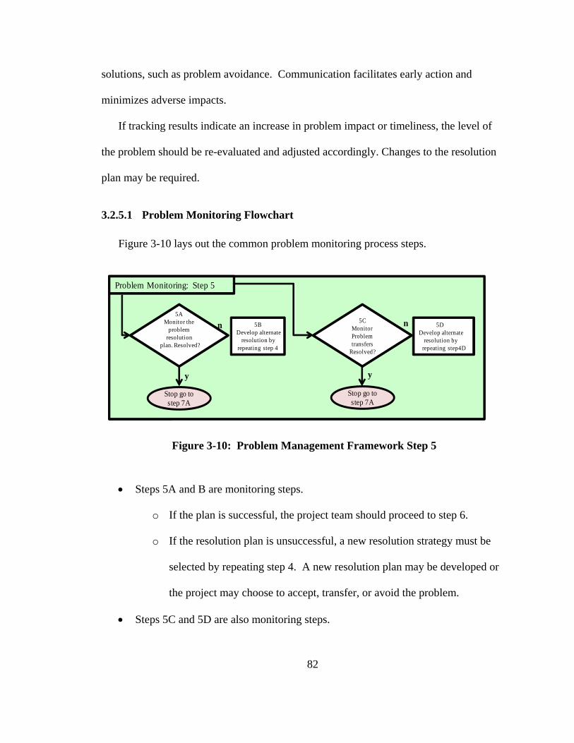
82
solutions, such as problem avoidance. Communication facilitates early action and
minimizes adverse impacts.
If tracking results indicate an increase in problem impact or timeliness, the level of
the problem should be re-evaluated and adjusted accordingly. Changes to the resolution
plan may be required.
3.2.5.1 Problem Monitoring Flowchart
Figure 3-10 lays out the common problem monitoring process steps.
Figure 3-10: Problem Management Framework Step 5
Steps 5A and B are monitoring steps.
o If the plan is successful, the project team should proceed to step 6.
o If the resolution plan is unsuccessful, a new resolution strategy must be
selected by repeating step 4. A new resolution plan may be developed or
the project may choose to accept, transfer, or avoid the problem.
Steps 5C and 5D are also monitoring steps.
Problem Monitoring: Step 5
5CMonitor Problem transfers
Resolved?
yy
nn5A
Monitor the problem
resolution plan. Resolved?
5DDevelop alternate
resolution by repeating step4D
5BDevelop alternate
resolution by repeating step 4
Stop go to step 7A
Stop go to step 7A

83
o If the party the problem was transferred to resolves the problem, the
project team should proceed to Step 6
o If the resolution plan is unsuccessful a new resolution strategy must be
selected and step 4 is repeated. A new resolution plan could thus be
developed or the project may choose to accept, transfer, or avoid the
problem.
3.2.6 Problem Closure - Step 6
A problem should be closed when:
It meets the target value stated in the resolution plan.
It no longer exists.
It is no longer cost effective to manage.
The project accepts the problem with no resolution.
The project is cancelled.
Information regarding closed problems is maintained in the problem database and
may be used as:
A baseline for monitoring problem resolution actions and verifying the results.
Background material for new projects and programs.
Rationale for future program decisions.
Identification of trends inside and outside of the project.
3.2.6.1 Problem Closure Flowchart
Figure 3-11 lays out the problem closure process steps we propose.

84
Figure 3-11: Problem Management Framework Step 6
Step 6A is a decision point. The problem manager decides the problem can be
closed.
Step 6B occurs when the project management team agrees and the problem is
closed.
Step 6C occurs if the project management team does not agree to close the
problem and returns to Step 4 to restart the process of deciding which additional
steps will be required to resolve remaining issues.
3.2.7 Problem Knowledge Management – Step 7
Knowledge management is a fundamental system engineering requirement[31, 32,
34]. All project documents and records should be captured by the project knowledge
management process though all stages of the project’s life cycle as part of the project’s
information management process. Individual problems along with successful and
Problem Closure: Step 6
yy
n
6AThe problem
has been resolved?
6CPermission Denied,
determine why and return to step 4 to adjust resolution strategy
6BObtain
permission to close the problem Document it in
the project problem database
yStop go to step 7A
6CGo to step 4
n

85
unsuccessful resolution plans are particularly valuable for future projects as the starting
point in the risk management process.
3.2.7.1 Problem Knowledge Management Flowchart
Figure 3-12 lays out our proposed knowledge management capture step.
Figure 3-12: Problem Knowledge Management Process Step 7
Step 7A captures all of the data collected to identify, analyze, assess, resolve,
strategize, monitors, reports, and closure justification for the problem.
4 Recommendations and Conclusions
4.1 Recommendation
The following describes a potential systems engineering process to manage problems
and recommends this process as an addition to the project’s Systems Engineering
Management Plan between the risk management process and the opportunity process.
For ease of understanding, the potential problem management process is formatted as
described in section 1.4 of the INCOSE handbook (V3.2)[1].
Problem Knowledge Management Process: Step 7
7ACollect all data associated with the problem and
document in the knowledge management system

86
4.1.1 Purpose
The following is a recommended purpose statement for a problem management
process:
The purpose of the problem management process is to identify, report, analyze,
develop resolution plans, assess impacts, and monitor problems as they are identified.
The problem management process systematically searches for problems, directs problems
with a potential for occurrence into the risk management process, and forwards risks
with 100% likelihood of occurrence into the problem management process. Each
problem is continuously managed for the life of the problem throughout the life cycle of a
system or service. Problem management can be applied to all phases of the system
engineering life cycle. A history of each identified problem is stored in the project
knowledge management system as a lesson learned for future projects.
4.1.2 Description
The primary objective of the problem management process is the early identification
of problems. To aid in identification, there are customized problem management
processes available for select applications. For instance, trouble call or trouble desks
may be used to address customer issues and capture resolution history as lessons learned
to solve future problems.
NASA created a Problem Management Guidebook called “The Procedural Handbook
for NASA Program and Project Management of Problems, Nonconformance’s, and
Anomalies”[4] which can be used for business related problems. The number one thing
trouble desks and the NASA problem process have in common is the decision to take a
proactive approach to problem management vice a reactive approach.

87
The problem process should be a proactive approach which aggressively identifies
potential problems and processes them in a manner similar to the risk management
process. For those problems identified, a formalized reactive problem management
approach is justified. No matter how the problem is identified (realized risk or stumbled
upon), processes of formalized reporting, root cause analysis, prioritization, resolution
planning and retirement planning should be in place prior to the beginning of the project
to capture and manage problems. The plan should lay out the project’s comprehensive
strategy for dealing with problems.
Like risk management, there are typical strategies for coping with problems,
including transference, avoidance, acceptance, and resolution planning. Strategy
selection may be determined by the scope and impact of the problem. In such instances,
a prioritization schema is critical to make certain that the right problems are addressed
with adequate assets allocated to ensure timely resolution of the problem.
Unlike risks, problems require immediate response to assess and determine their
impact to the project. By having a rapid assessment process in place as part of the
problem management process, a quick initial decision can be made by the project staff.
Those problems with the greatest potential to derail the project will, of necessity, receive
most of the project management team’s attention and project resources.
Figure 4-1 depicts a notional context diagram in the format of INCOSE Handbook
version 3.2 [1] for the proposed problem management process.

88
Figure 4-1: Context Diagram for the Problem Management Process Inputs to
Activities
Inputs to the problem management process include the following:
Identified problems as a result of technical reviews, audits, or other scheduled project
reviews.
Realized risk(s) from the risk management process.
Unplanned events and suspected problems identified by abnormalities in the Earned
Value Management System or Technical Performance Monitoring System.
Frequently problems are identified late in the life cycle of a system. Speciality
engineering activities, cost-effectiveness analysis, environmental impact analysis, life
cycle cost analysis and other activities can also be used to identify problems that
significantly impact the project.
The problem management process is controlled by:
Activities-Problem Management Planning-Manage the Problem Profile-Analyze Problems-Resolve Problems-Execute the Problem Management Process
Controls-Applicable Laws and Regulations-Government and Industry Standards-Contracts and Agreements-Project Procedures, Plans, and Standards Directives- Corporate Code of Ethics-System Engineering Processes
Enablers-Organization/Enterprise Policies, Procedures, Plans, and Standards-Organization /Enterprise Infrastructure-Project Infrastructure
Inputs-Identified Problems-Realized Risks-Unplanned Events
Outputs-Problem Management Plan-Problem Profile-Problems Reports-Knowledge Management Inputs- Problem Resolution Plans

89
Applicable laws and regulations.
Government and industry standards.
Contract agreements.
Project-specific procedures, plans, standards, directives and planning documents.
The corporations code of ethics.
System engineering processes.
The problem management process is enabled by the following:
Organization/Enterprise policies, procedures, plans and standards.
Organization/Enterprise infrastructure
Project infrastructure
4.1.3 Outputs from Activities
Outputs from the problem management process include the following:
Project problem management plan.
Problem profile (Inventory) – A database similar to the project risk register from which a
problem matrix can be extracted to display an inventory of problems (open, closed and
accepted). Problem matrices are similar to risk matrices as they are developed using
cognitive biases [45] which affect the placement of problem points developed by
assigning a numerical value to each level.
Problem Report – the vehicle used to communicate the current problem inventory to the
project stakeholders. Problems reports are highly customized for the particular audience.
For select problems (as determined by the project problem management team), detailed
problem resolution plans, root cause analyses, and impact assessments are developed. In
addition, a list of alternatives solutions is generated for project management decision
making.

90
Problem management knowledge transfers to lessons learned, knowledge management
systems, and other projects.
4.1.4 Process Activities
The Problem management process includes the following activities:
Plan problem management:
Defining the problem identification process by establishing project specific
thresholds (cost, schedule, technical, programmatic, and safety
environmental) to determine problem initial reporting levels.
Defining and documenting the problem management strategy.
Defining and documenting the problem management process.
Establishing criteria for what a problem is and defining the boundaries of
which problems to deal with first – i.e. an assessment criteria to help the
project establish priorities.
Developing and implementing a communications plan to keep stakeholders
informed of the project’s problems.
Problem analysis:
Conducting root cause analysis.
Analyzing the problem to determine the magnitude of the impact and the
timeliness.
Determining a resolution plan and the amount of additional resources to be
allotted to resolving the problem.
Determining the person or organization responsible for resolution plan
execution and continuous reporting of the problem resolution status.

91
Reporting (at a minimum) the problem’s cost to date, cost expected in the
future, schedule impact to date, schedule impacts expected in the future,
safety impacts, technical issues and fallbacks.
Problem resolution:
Using established problem boundary criteria to identify those problems
which require an approach which is inside of the project charter. In an ideal
project, this class of problems would have been already entered into the risk
management system and have a mitigation plan which failed to prevent the
risk from being realized or, if no fallback (work-around) plan has been
prepared, a problem resolution plan and alternative strategies to deal with
the problem would be developed. It is noteworthy that mitigation plans are
developed to prevent risks from being realized (addresses a potential future),
while resolution plans are developed to address the impacts of a problem (in
the present).
For problems identified outside of the risk management process, the
established problem boundary criteria for dealing with problems within the
project charter should be used to develop a problem specific resolution
action plan and alternative strategies to resolve or reduce the problem to an
acceptable level.
Presenting the potential resolution plans to the project management team,
who will select the optimum strategy and authorize execution of the plan.
Management of the problem profile:

92
Developing a comprehensive problem register in which a record of problem
items is kept, including: date identified, personnel involved, actions to date,
root cause analysis, assessment and assessment basis, timeliness, resolution
action plan, and every communication dealing with the problem.
Development of an electronic problem register is recommended. One
potential solution is development of an extension of the project risk
management software to capture problems (and opportunities) in one readily
available central location.
Developing a two-way interface between the problem management register,
the projects risk management register, and the project knowledge
management system.
Evaluation of the problem management process:
Developing a problem management plan or adding a chapter to the project
processes section of the project’s SEMP.
Common approaches and recommendations:
Customizing an established risk management plan to meet the problem management
needs of the project.
Establishing a project-specific document used to aid in the documentation of individual
problems. Like the Risk Information Sheets, a Problem Resolution Sheet documents a
description of an individual problem, assessment (initial and current), priority, resolution
plan, and the primary and secondary points of contact for information regarding the
problem.

93
Extending the risk rule of thumb of using “If <situation> , then <consequence> as a
question to pose for each risk candidate” [1] for problem management, the recommended
rule of thumb is “Currently < to describe the problem as it currently is> and Timeliness
<to describe the problem in the context of time to project termination>” [4] Timeliness is
a concept developed by NASA as part of their “Procedural Handbook for NASA Program
and Project Management of Problems, Non-conformances, and Anomalies”. [4]
A complete record of all actions and persons involved with the problem cause,
identification, analysis of current and future impact, resolution actions to date, and
management decisions will aid in recreating the problem environment, which will
significantly aid the project in planning future resolution actions, determining how much
project assets were expended in problem resolution, and determining who the action
parties were.
Use tools to identify problems and potential resolution actions. Common methods are:
Failure Modes and Effects Analysis (FMEA),a formal process or study in
which a subject is examined in detail and risk is assessed.[50] The FMEA
process is proactive and can be used to determine why, where, and how
failure occurred and to assess the relative impact of different failures in
order to identify the parts of the process that are most in need of change.
Trend Analysis/Data Mining, a process used by NASA to uncover patterns
and trends from existing databases in order to employ problem management.
[4]
Apollo Root Cause Analysis method, simple tools and the knowledge
necessary to find effective solutions. [49]

94
The Procedural Handbook for NASA Program and Project Management of
Problems, Non-conformances, and Anomalies, an excellent source as basic
guidance in the development and understanding of safety- and technical-related
problem management.
ISO/IEC guides and risk assessment techniques, excellent starting points for
common definitions.
4.2 Conclusions
“People understand that bad things can happen, what they do not forgive is
unpreparedness”[2]. The INCOSE system engineering process is the recognized
methodology to develop a system by resolving the inherent design, engineering and other
lifecycle problems using a methodical, proven process. Embedded in the process are sub-
processes to manage risk and opportunities. One key process is missing: problem
management.
The larger the project, the more likely it is that significant problems will occur. Risk
management addresses known potential problems with robust planning and mitigation.
When risk management is unsuccessful, the risk should be closed and problem
management should take over. Unfortunately INCOSE does not provide a framework or
process to aid in the management of problems.
This paper provides a starting point for a problem management process that could be
added to the next revision of the INCOSE handbook. It is recommended for insertion
into Chapter Five, Project Processes as a task between risk and opportunity management.
Overall, it would be best if the risk, opportunity and problem management processes
were combined into one comprehensive framework which could be adapted to each

95
projects use. It is critical that projects understand the full spectrum of problems they face
not only in the beginning of the project but throughout the entire project life cycle. The
management team must be fully informed with the latest information available on all of
the problems at any given moment. The team must communicate with all stakeholders
about what the problems are and what the actions are being undertaken to resolve them.
INCOSE is the appropriate professional authority to sponsor and establish a robust
System Engineering Problem Management process.
5 Recommendation for Future Research
5.1.1 Opportunity Management Framework
The current opportunity management section of the INCOSE handbook lacks clarity.
A review of other literature sources indicates that other, more comprehensive research
has been conducted but fails to address the following situations:
If an opportunity has been successfully achieved what is it called? It should no
longer be called an opportunity to help separate the gains from what has not yet
been realized.
When an opportunity does succeed, does the project management team harvest the
gains from the successful department or does the project redirect the gains to
other areas?
When the gain is on schedule how does the project reward the successful
department? Do they close the department early and lay off people? Do they add
more work to the successful department? The penalties for successfully

96
harvesting a project can be detrimental to the success of the project opportunity
management system.
In many cases there is no sure way to determine if the opportunity has been
realized. What is the method used to determine if the opportunity enhancement
plan was successful needs to be developed?
5.1.2 Problem, Risk, Opportunity, Realized Opportunities, and Earned Value
Management Integration
A review of the INCOSE handbook and the applicable standards indicates there is no
chapter on earned value management. U.S. government and many commercial contracts
require a certified earned management system be in place at the beginning of a project’s
life cycle. Earned value has significant interfaces with many systems engineering and
project management processes. Additional research in the areas below is recommended:
Earned value interfaces with systems engineering processes such as risk,
opportunity, and decision management.
Tailoring earned value based on the systems engineering technical
performance management process.
The effects of aligning the earned value management work breakdown
structure with the systems engineering work breakdown structure.
5.1.3 Total Systems Engineering Framework
Additional research could be conducted to further the development of a total systems
engineering framework which incorporates all of the various systems engineering and

97
management processes reviewed in Chapter 2 of this paper. The goal is a comprehensive
framework that integrates the best of the best of the various frameworks currently in use
by project teams. The framework should, at a minimum, establish a hierarchy of what
processes are needed at what stages of a project life cycle and ensure all needed processes
are included in the SEMP and project planning documents. The comprehensive systems
engineering framework could be used as a guide in contract negotiations to ensure the
project has priced the right work at the right time in the project life cycle.

98
6 BIBLIOGRAPHY
[1] R. D. Hamelin, et al., INCOSE Systems Engineering Handbook vol. 3.2:
INCOSE, 2010. [2] B. A. Olson, et al., "Problem Management Process, Filling the Gap in the Systems
Engineering Processes between the Risk and Opportunity Processes," Systems Engineering, vol. 15, 2012.
[3] P. F. R. a. M. King, "Problem Management: What Happens When Risks Become Problems? ," P. F. Richardson, Ed., ed: NASA, 2005.
[4] NASA, "Procedural Handbook for NASA and Project Management of Problems, Non-conformances, and Anomalies," S. a. M. Assurance, Ed., Baseline ed. Washington DC: NASA, 2008, p. 86.
[5] ISO/IEC, "ISO/IEC Standard for Systems Engineering - Application and Management of the Systems Engineering Process," ISO/IEC 26702 IEEE Std 1220-2005 First edition 2007-07-15, pp. c1-88, 2007.
[6] J. J. Randolph, "A Guide to Writing a Dissertation Literature Review," Practical Assessment Research and Evaluation, vol. 14, p. 13, June 2009 2009.
[7] A. Kossiakoff and W. N. Sweet, "Systems Engineering Principles and Practice," ed: John Wiley & Sons, 2003.
[8] A. D. Hall, A methodology for systems engineering: Van Nostrand, 1962. [9] B. S. Blanchard and W. J. Fabrycky, Systems engineering and analysis: Prentice-
Hall, 1981. [10] D. A. University, Risk management guide for DOD acquisition: Dept. of Defense,
Defense Acquisition University, 2002. [11] J. Wasek, "Introduction to Architectural Frameworks and Enterprise
Architecting," in System Architecture: The Goal, ed. Washington DC: Department of Engineering Management & Systems Engineering (EMSE) George Washington University, 2009.
[12] I. Merriam-Webster, Merriam-Webster's collegiate dictionary: Merriam-Webster, 1993.
[13] S. A. Bernard, An introduction to enterprise architecture: Authorhouse, 2004. [14] P. Checkland, Systems thinking, systems practice: John Wiley, 1999. [15] H. Eisner, Essentials of project and systems engineering management: Wiley,
1997. [16] A. P. Sage and C. L. Lynch, "Systems integration and architecting: An overview
of principles, practices, and perspectives," Systems Engineering, vol. 1, pp. 176-227, 1998.
[17] G. Rebovich. (2010). Enterprise Systems Engineering : Advances in the Theory and Practice (1 ed.). Available: http://gwu.eblib.com/patron/FullRecord.aspx?p=555713
[18] K. Forsberg, et al., Visualizing project management: Wiley, 1996. [19] B. Reed, "Integration, Verification And Validation," in Professional Certificate in
Systems Engineering vol. IV&V, ed. Newport News: Reed Integration INC, 2007.

99
[20] H. M. Kevin Forsberg, "The Dual Vee Illuminating the Management of Complexity " in System Engineering: Shining Light on the Tough Issues, Orlando FL, 2006, p. 32.
[21] R. Beers, "Risk Management Fundamentals," D. o. H. Security, Ed., ed. Washington DC: Homeland Security, 2011, p. 31.
[22] A. B. Kumley, P. ; Coleman, R. ; Abba, W. ; Infanti, G. ; Driessnack, J., "Integrating Risk Management with Earned Value Management: A Statistical Analysis of Survey Results," in 5th:, JOINT INTERNATIONAL CONFERENCE AND EDUCATIONAL WORKSHOP, Denver, 2005, p. 32.
[23] Lexmart, "Perceptive," 6.5 ed. Kansas City: Lexmart, 2011, p. Contract Management Software.
[24] U. Software, "Upside Contract ", 7.1 ed. Alberta, Canada: Upside Software Inc, 2011.
[25] C. Logix, "Contract Management Solutions," ed. Chelmsford, MA, 1997. [26] C. L. Pritchard, Risk management: concepts and guidance: Taylor and Francis,
2005. [27] J. Miller. (2011, The Definition of Risk Management in Health Care. Available:
http://www.ehow.com/about_6619711_definition-risk-management-health-care.html
[28] B. O. Dictionary. (2011, November 22, 2011). Financial Risk [Electronic]. Available: http://www.businessdictionary.com/definition/financial-risk.html
[29] A. J. Dorofee, et al., Continuous risk management guidebook: Carnegie Mellon University, 1996.
[30] N. N. S. Administration, "Managing Design and Construction Using Systems Engineering," vol. DOE G 413.3-1, D. o. Energy, Ed., ed. Washington DC: Department of Energy, 2008, p. 66.
[31] B. Fagerström and L.-E. Olsson, "Knowledge management in collaborative product development," Systems Engineering, vol. 5, pp. 274-285, 2002.
[32] B. Serenko, Hull, "Practical relevance of knowledge management and intellectual capital scholarly research: Books as knowledge translation agents," Knowledge and Process Management, vol. 18, pp. 1-9, Feb 2011 2011.
[33] Interspire. (2011, Software). Interspire Knowledge manager (5.0 ed.). Available: http://www.interspire.com/knowledgemanager/
[34] M. Rao, Knowledge management tools and techniques: practitioners and experts evaluate KM solutions: Elsevier Butterworth-Heinemann, 2005.
[35] E. Fricke, et al., "Coping with changes: Causes, findings, and strategies," Systems Engineering, vol. 3, pp. 169-179, 2000.
[36] R. Krikhaar, et al., "Enabling system evolution through configuration management on the hardware/software boundary," Systems Engineering, vol. 12, pp. 233-264, 2009.
[37] Y. Liu, et al., "Configuration management process design and implementation," in Computing, Communication, Control, and Management, 2009. CCCM 2009. ISECS International Colloquium on, 2009, pp. 4-7.
[38] T. Lewis, "Quantitative approach to technical performance measurement and technical risk analysis utilizing Bayesian methods and Monte Carlo simulation,"

100
The George Washington University Ph.D., The George Washington University, United States -- District of Columbia, 2010.
[39] K. M. Pro. (2011, Knowledge Management (6.0.3 ed.). [40] E. M. Gramlich, A guide to benefit-cost analysis: Waveland Press, 1990. [41] P. J. Solomon, "Integrating Systems Engineering with Earned Value
Management," Defense AT&L, vol. 33, pp. 42-46, 2004. [42] S. Adams, ITIL V3 foundation handbook: Stationery Office, 2011. [43] A. Roe, "Making of a Scientist " in New York City New York, ed: Praeger, 1974,
p. 244. [44] M. H. Roberts. (2010, Project Management Jokes Humour Proverbs and Laws
(2nd ed.). Available: http://www.hraconsulting-ltd.co.uk/project-management-jokes-humour-proverbs-laws.htm
[45] E. D. Smith, et al., "Risk matrix input data biases," Systems Engineering, vol. 12, pp. 344-360, 2009.
[46] Toyota.com. (2011, Toyota Announces Two Voluntary Recalls and Amends Potential Floor Mat Interference Recall Announced in 2009. Available: http://pressroom.toyota.com/safety-recall/
[47] T. V. Wilson. (07 September 2006, Why are space shuttle launches delayed so frequently? [Electronic].
[48] T. Al Neimat. (2005, Why IT Projects Fail. The Project Perfect White Paper Collection [White Paper]. 8. Available: http://www.projectperfect.com.au/downloads/Info/info_it_projects_fail.pdf
[49] A. A. S. LTD, "Apollo Root Cause Analysis," A. LTD, Ed., February 2006, R2 ed: Apollonian Publications LLC, 2005.
[50] M. A. Anleiter, The power of deduction : failure modes and effects analysis for design Milwaukee: ASQ Quality Press, 2010.