prob10.pdf
TRANSCRIPT

Electromagnetism 70006 Answers to Problem Set 10 Spring 2006
1. Jackson Prob. 5.15: Shielded Bifilar Circuit: Two wires carrying oppo-sitely directed currents are surrounded by a cylindrical shell of inner radiusa, outer radius b, and relative permeability µr.
(a) Determine the magnetic potential for two wires; the first is locatedat x = d/2 and carries current I in the -z direction and the secondis located at x = −d/2 and carries current I in the z direction.
Φm =I
2πln
(√ρ2 + d2/4− dρ cosφ√ρ2 + d2/4 + dρ cosφ
)≈ − I
2π
cos φ
ρ,
where φ is measured counter-clockwise from the x axis.(b) Find the potential in the three regions. We may assume that only
terms in the expansion of the potential in cylindrical coordinatesproportional to cos φ contribute:
Φm =[Aρ +
κ
ρ
]cosφ ρ < a
=[Bρ +
C
ρ
]cos φ a < ρ < b
=D
ρcosφ b < ρ,
where κ = −I/(2π) and where (A, B, C, D) are unknown expansioncoefficients to be determined by boundary coefficients on the twosurfaces ρ = a and ρ = b. These conditions; Φm continuous andnormal component of B continuous, lead to the equations:
A +κ
a2= B +
C
a2
−A +κ
a2= µr
(−B +
C
a2
)
B +C
b2=
D
b2
µr
(−B +
C
b2
)=
D
b2
Solving, we find
Φa =
[(a2 − b2)κ
(µ2
r − 1)
a2 (b2(µr + 1)2 − a2(µr − 1)2)ρ +
κ
ρ
]cosφ
Φb =[
2κ(µr − 1)b2(µr + 1)2 − a2(µr − 1)2
ρ +2b2κ(µr + 1)
b2(µr + 1)2 − a2(µr − 1)21ρ
]cosφ
Φc =[
4b2κµr
b2(µr + 1)2 − a2(µr − 1)21ρ
]cosφ
1

Substituting into the earlier expression gives explicit results for Φm
in each region. In particular, outside the shield we find a dipolepotential with coefficient proportional to that of the two wires (κ);the coefficient of proportionality is
F =4b2µr
b2(µr + 1)2 − a2(µr − 1)2.
In problem 5.14, a uniform external field maintained its form butwas reduced in strength inside a cylindrical shield. Here an internaldipole field maintains it’s form but is reduced in strength outside acylindrical shield.
(c) For µr À 1 and b = a+ t with t ¿ b, we find (µr = 200, b = 1.25 cm,t = 0.3 mm)
F ≈ 2b
tµr= 0.417
2. Jackson: Prob. 5.24: For a conducting plane with a circular hole and atangential field H0 on one side:
(a) Determine H(1) on the side with H0 for ρ > a. We have for z = 0
Φ(1)(ρ, φ) =2aH0
π
∫ ∞
0
j1(ka)J1(kρ)dk sin φ
=H0
π
(ρ sin−1
(a
ρ
)− a
√1− a2
ρ2
)sinφ. ρ > a.
For ρ > a, we find
Hρ = − ∂Φ(1)
∂ρ
=H0
π
a3
√1− a2
ρ2 ρ3+
a√1− a2
ρ2 ρ− sin−1
(a
ρ
) sin φ
Hφ =∂Φ(1)
ρφ
=H0
π
[a
ρ
√1− a2
ρ2− sin−1
(a
ρ
)]cosφ
Hx = Hρ cos φ−Hφ sin φ =H0
π
a3
ρ2
sin 2φ√ρ2 − a2
=2H0
π
a3
ρ4
xy√ρ2 − a2
2
Hy = Hρ sin φ + Hφ cos φ =H0
π
[a√
ρ2 − a2− sin−1
(a
ρ
)− a3
ρ2
cos 2φ√ρ2 − a2
]
=2H0
π
a3
ρ4
y2
√ρ2 − a2
+H0
π
[a
ρ2
√ρ2 − a2 − sin−1
(a
ρ
)]
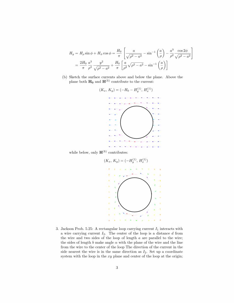
(b) Sketch the surface currents above and below the plane. Above theplane both H0 and H(1) contribute to the current:
(Kx, Ky) = (−H0 −H(1)y , H(1)
x )
while below, only H(1) contributes:
(Kx, Ky) = (−H(1)y , H(1)
x )
3. Jackson Prob. 5.25: A rectangular loop carrying current I1 interacts witha wire carrying current I2. The center of the loop is a distance d fromthe wire and two sides of the loop of length a are parallel to the wire;the sides of length b make angle α with the plane of the wire and the linefrom the wire to the center of the loop The direction of the current in theside nearest the wire is in the same direction as I2. Set up a coordinatesystem with the loop in the xy plane and center of the loop at the origin;
3

the sides a run parallel to y and are located at x = ±b/2; the sides b areparallel to the x axis. The wire located at z = d sinα, x = d cos α andI2 flows along +y. In this coordinate system, the vector potential of thewire has only a y component and
A2 = − I2
4πln[(x− d cos α)2 + (z − d sin α)2] y
(a) The interaction energy is
W12 = I1
∮dl1 ·A2
=µ0I1I2
4πa ln
[(−b/2− d cosα)2 + (−d sin α)2
(b/2− d cos α)2 + (−d sinα)2
]
=µ0I1I2
4πa ln
[4d2 + b2 + 4db cosα
4d2 + b2 − 4db cosα
]
where only the two sides parallel to y contribute.
(b) Calculate the force on the loop We have in the xy plane
Bx(x, 0) = − ∂Ay
∂z
∣∣∣∣z=0
=−d sin α
(x− d cosα)2 + d2 sin2 α
Bz(x, 0) =∂Ay
∂x
∣∣∣∣z=0
=(x− d cos α)
(x− d cos α)2 + d2 sin2 α
The force on the two sides of the rectangle of length b precisely cancel.The x and z components of the force on the two sides of length a are
Fx = I1[Bz(b/2, 0)−Bz(−b/2, 0)] =2µ0I1I2 ab
(4d2 cos(2α)− b2
)
π (b4 − 8d2 cos(2α)b2 + 16d4)
Fz = − I2[Bx(b/2)−Bz(−b/2, 0) = − 8µ0I1I2 ab d2 sin(2α)π (b4 − 8d2 cos(2α)b2 + 16d4)
(c) Repeat for the case where the rectangle of sides a, b is replaced by acircle of radius a. In this case, we write
W12 = I1
∫ 2π
0
a cos φAy(a cosφ, 0) dφ,
where we have used the fact that x = a cosφ and dly = a cosφ dφalong the circle. We expand the Ay in a series in powers of 1/d andcarry out the integral term by term to find
W12 = I1I2µ0a
(cos(α)a
2d+
cos(3α)a3
8d3+
cos(5α)a5
16d5
+5 cos(7α)a7
128d7+
7 cos(9α)a9
256d9
)
4

The same series results if we evaluate W12 = I1Φ2, where Φ2 is themagnetic flux through the circle. Note that the term in parenthesesabove can be written
(· · ·
)= <
{z
2+
z3
8+
z5
16+
5z7
128+
7z9
256
},
Wherez =
a
deiα
Moreover,
1−√1− z2
z=
z
2+
z3
8+
z5
16+
5z7
128+
7z9
256
Thus, we may write
W12 = I1I2µ0a<{
1−√1− z2
z
}with z =
a
deiα
This correct answer is close (but not identical) to the answer givenin the text. Indeed, if we assumed
<{
1−√1− z2
z
}=
1−√
1− (<z)2
<z,
then we would recover the result in the text.Find the force.
F = i I1
∫ 2π
0
a cos φBz(a cos φ, 0) dφ−k I1
∫ 2π
0
a cos φBx(a cos φ, 0) dφ
Again, expanding the potential and carrying out the integrationsleads to We find
Fx = µ0I1I2
(cos(2α)a2
2d2+
3 cos(4α)a4
8d4+
5 cos(6α)a6
16d6
+35 cos(8α)a8
128d8+
63 cos(10α)a10
256d10
)
Fz = µ0I1I2
(sin(2α)a2
2d2+
3 sin(4α)a4
8d4+
5 sin(6α)a6
16d6
+35 sin(8α)a8
128d8+
63 sin(10α)a10
256d10
)
Again, we can identify the two series: Consider the function
G(z) =1√
1− z2− 1 =
z2
2+
3z4
8+
5z6
16+
35z8
128+
63z10
256
5

Comparing, we find
Fx = µ0I1I2<G(a
deiα
)
Fz = µ0I1I2=G(a
deiα
)
(d) Express the energies for large d in terms of moments of loops. Forthe rectangular loop:
W12 =µ0I1I2
4πa ln
[4d2 + b2 + 4db cosα
4d2 + b2 − 4db cosα
]
→ µ0I1I2
4πa
2b cos α
d= (I1ab)
µ0I2
2πdcos α = m1B2z
For the circular loop:
W12 = I1I2µ0a
(cos(α)a
2d+
cos(3α)a3
8d3+
cos(5α)a5
16d5+ · · ·
→ I1I2µ0acos(α)a
2d= (I1πa2)
µ0I2
2πdcos α = m1B2z
In both cases, the + sign is a result of the fact that the moment andthe normal component of the field are in opposite directions.
4. Jackson Prob. 5.34: Two identical circular loops are located a distance Rapart on a common axis,
(a) Find M12 using Aφ from Prob. 5.10b:
Aφ(ρ, z) =µ0I1a
2
∫ ∞
0
J1(ka)J1(kρ)e−k|z|dk
W12 = I2
∫ 2π
0
a dφAφ(a,R) = µ0I1I2πa2
∫ ∞
0
J1(ka)J1(ka)e−kRdk
Leading to the result
M12 = µ0πa2
∫ ∞
0
[J1(ka)]2e−kRdk
(b) Assuming a << R, we obtain an asymptotic series in R by expandingJ(ka) in a power series
[J1(ka)]2 ≈ a2k2
4− a4k4
16+
5a6k6
768− 7a8k8
18432
Integrating, we find
M12 =µ0aπ
2
(a3
R3− 3a5
R5+
75a7
8R7− 245a9
8R9+ · · ·
)
6

(c) Find the mutual inductance for co-planer loops with centers sepa-rated by R. The axial Bz field from the loop centered at the originis
Bz(z) =µ0I1
2a2
[a2 + z2]3/2
This field can be derived from a scalar potential
Φm(z) =µ0I1
2
[1− z√
z2 + a2
]
=µ0I1
2
(a2
2z2− 3a4
8z4+
5a6
16z6− 35a8
128z8+
63a10
256z10+ · · ·
).
Analytically continuing the potential leads to
Φm(r, θ) =µ0I1
2
(a2
2r2P1(cos θ)− 3a4
8r4P3(cos θ) +
5a6
16r6P5(cos θ)
− 35a8
128r8P7(cos θ) +
63a10
256r10P9(cos θ) + · · ·
)
We need Bz at large values of r and θ = π/2. We find
Bz(r, π/2) =1r
∂Φm
∂θ
∣∣∣∣θ=π/2
=µ0I1
2
(a2
2r3+
9a4
16r5+
75a6
128r7+
1225a8
2048r9+
19845a10
32768r11
)
Introduce the vector ρ centered on the second loop. Then we maywrite bmr = R+ρ, where R is the vecror from the center of the firstloop to the center of the second. We may replace
r →√
R2 + ρ2 + 2Rρ cos φ
where φ is the polar angle with respect to the center of the secondloop and carry out a second expansion of Bz with respect to R. Withthis in hand, we calculate the flux Φ2 the through the second loop.First, integrating Bz over the polar angle φ, we obtain
∫ 2π
0
Bzdφ =µ0I1π
2
{a2
R3+
(9a4
8+
9ρ2a2
4
)1
R5
+(
75a6
64+
225ρ2a4
32+
225ρ4a2
64
)1
R7
+(
1225a8
1024+
3675ρ2a6
256+
11025ρ4na4
512+
1225ρ6a2
256
)1
R9
}
7

To evaluate the flux through the second loop, we integrate the pre-vious result over ρ
Φ2 =∫ a
0
ρdρ
∫ 2π
0
Bzdφ =
µ0I1πa
4
(a3
R3+
9a5
4R5+
375a7
64R7+
8575a9
512R9
)
Given that Φ2 = M12I1, we may write
M12 =µ0πa
4
(a3
R3+
9a5
4R5+
375a7
64R7+
8575a9
512R9
)
(d) calculate the force in each case. For the co-planar loops, the onlynon-vanishing component of the force on the second loop is
Fx = I2
∫ ∞
0
a cosφBz(ρ = a, φ)dφ
=µ0I1I2π
2
(3a4
2R4+
45a6
8R6+
2625a8
128R8+
77175a10
1024R10
)
The force is repulsive and along the line joining the centers of theloops.In the case of the co-axial loops, only the component Fz of the forceon the second loop contributes:
Fz = cos θFr − sin θFθ.
Now, at the location of the second loop, components of the force are
Fr = − 2πa I2 Bθ(r, θ)Fθ = 2πa I2 Br(r, θ),
where r =√
a2 + z2 and θ = arccos(z/√
a2 + z2). Therefore,
Fz = −2πa I2 (cos θBθ(r, θ)− sin θBr(r, θ))
Substituting and expanding the fields in z, one obtains
Fz = I1I2µ0π
(− 3a4
2R4+
15a6
2R6− 525a8
16R8+
2205a10
16R10
)
The force is attractive and along z.
8