proactive ethernet congestion control based on link ...€¦ · proactive ethernet congestion...
TRANSCRIPT

Proactive Ethernet Congestion Control Based onLink utilization Estimation
Mahmoud Bahnasy∗, Bochra Boughzala‡, Halima Elbiaze†, Brian Alleyne‡, Andre Beliveau‡§, Chakri Padala‡
∗Ecole de Technologie Superieure, [email protected]†Universite du Quebec a Montreal, [email protected]
‡Ericsson, {bochra.boughzala,brian.alleyne,andre.beliveau,chakri.padala}@ericsson.com
Abstract—In the quest of providing a deterministic backplane-like behaviour a mechanism called ECCP (Ethernet CongestionControl & Prevention) was proposed where specialized andexpensive devices were replaced by commodity Ethernet switcheswhile still keeping the router properties, e.g. low-latency packetdelivery, no packet loss within the fabric and fair share ofthe bandwidth. However, ECCP uses a self-induced congestionprobing model which can cause queue length fluctuation inaddition to the network bandwidth wastage due to the probes.Therefore, we propose enhancements to the algorithm used byECCP to reduce probe packet overhead. In our solution NoP-ECCP (ECCP with no probes), we use a link utilization estimationtechnique instead of the estimation of the available bandwidth.The results obtained through simulations show that NoP-ECCPoutperforms ECCP in terms of fairness, link utilization and queuelength.
Keywords—Congestion Control, Ethernet, Switch fabric.
I. INTRODUCTION
Traditional routers are built in a monolithic structure whereall the line cards are placed in a single chassis and they areconnected together through the backplane. One of the maincharacteristics of a switch fabric in routers is that every packetthat comes from an ingress line card into the fabric has tobe delivered to the egress line card within a deterministicdelay [1], [2]. In fact, the switch fabric requires guaranteedlow latency packet delivery, fairness in bandwidth allocation,no packet loss and no head-of-line blocking behavior. Thus,specialized chips and proprietary protocols are applied in theswitch fabric in order to maintain these tight properties in termsof bandwidth allocation and latency. These vendor-specificsolutions are very expensive and they also have scalabilitylimitations. In fact, with a rigid backplane it is not possible toexpand the router and add more line cards unless the completedesign of the entire system is reviewed.
In the other hand, Data Center Networks depict the fieldwhere flexible fabric is used to interconnect servers andnetwork switches. Some enhancements, like QCN [3], [4], [5],are proposed by the IEEE Data Center Bridging (DCB) [6],[7] working group to introduce quality of service mechanismsin Data Center Networks. In addition, Data Center Networksuse over-provisioning and they don’t guarantee packet deliveryat Layer 2 so they rely on the upper protocols like TCP toretransmit lost or dropped packets.
§ This author is no longer at Ericsson Research.
Our previous work [8] explored the possibility to deploya router in a distributed fashion where the authors developeda new protocol called ECCP in order to replace the special-ized switch by a standard Ethernet commodity switch. ECCPuses self-induced congestion probing model to estimate theavailable bandwidth. This model may generate probe trainsof rates higher than the available bandwidth which can causequeue length fluctuation. In addition, ECCP probing modelrequires fixed inter-frame intervals and fixed frame size whichprevent using data as probes. In this paper, we proposeestimating link utilization instead of the available bandwidthand we implement a mechanism that combines ECCP with linkutilization estimation.
The rest of the paper is organized as follows: SectionII gives background to ECCP and identifies its limitations.Section III introduces the link utilization estimation technique.Section IV provides detailed description about our proposedsolution NoP-ECCP. The performance evaluation of the pro-posed solution is presented in Section V. Finally, Section VIpresents the conclusion and future work.
II. ETHERNET CONGESTION CONTROL AND PREVENTION(ECCP)
ECCP is proposed as a congestion control mechanism forEthernet networks. It is a distributed algorithm that can runeither on end-hosts or the router’s line cards without the needof switch participation. ECCP aims to keep the link utilizationunder the maximum link capacity by a certain percentage(Availability Threshold AvT ). ECCP uses the estimation ofthe available bandwidth (AvBw) in order to limit the line cardSending Rate (R).
ECCP’s main components are depicted in Fig. 1. ECCPprobe sender starts the control cycle by sending probe trainsof N packets each. ECCP probe sender stamps each probepacket with its sending time. Probe rate µ is limited by theavailable bandwidth margin which is equal to the availabilitythreshold percentage of the sending rate (AvT × R). At thereceiving line card, the probe receiver receives the probes,reads their information, adds receiving time, and then forwardsthis information to the bandwidth estimator. ECCP bandwidthestimator uses a modified version of BART (Bandwidth Avail-able on Real Time) [9] to estimate AvBw and then sendsthis information back to the paired line card. Once ECCP ratecontroller receives AvBw information, it calculates a feedbackvalue (Fb) and then it controls the sending rate (R) according

AvBw Estimation Path Probe frames Path Data Path Control Path
ECCP Agent (Sender)
ECCP Controller
Rate Controller
Probe Sender
Probe Receiver Bandwidth Estimator
Input / Output
Rat
e Li
mite
r ECCP Estimator
ECCP Agent (Receiver)
ECCP Estimator
Rate Controller
Probe Sender
Probe Receiver Bandwidth Estimator
Input / Output
Rat
e Li
mite
r
ECCP Controller
Data Packet
Probe Packet
Estimation Packet
Switch
Fig. 1. ECCP’s main Components
to the Additive Increase Multiplicative Decrease (AIMD) [10],[11] principle (Equation 1).
R←{R(1−Gd × |Fb|) if Fb < 012 (R+ TR) otherwise
(1)
Where Gd is a fixed value and is taken in a way thatGd|Fbmax
| = 12 and TR is the target rate which is equal to
the last sending rate before congestion.
Similarly to QCN reaction point algorithm [5], ECCP rateincrease process defines three phases: Fast Recovery (FR),Active Increase (AI) and Hyper-Active Increase (HAI).
ECCP determines the increasing phases based on aByteCounter and a Timer (Fig. 2). The Fast Recovery phasedefined by 5 cycles, where each cycle consists of 150 KBytesof data transmission. In case the host sending rate is very slow,the end of the cycle is triggered by the Timer expiration(T = 3ms). After each cycle, the rate controller changes Raccording to equation 1 while keeping TR unchanged.
Fig. 2. ECCP rate control phases
If the ByteCounter or the Timer completes 5 cyclesin FR phase without calculating negative feedback, the ratecontroller enters the Active Increase phase and increases TRby RAI = 5Mbps. In this phase, the ByteCounter counts75 KBytes for each cycle, and the Timer counts T/2. Finally,if both the ByteCounter and the Timer complete 5 cycles,
the rate controller enters the Hyper-Active Increase phase andincreases TR by RHAI = 50Mbps (Further details can befound in [8]).
The main advantages of using ECCP are that it has aproactive control on the sending rate and it doesn’t waitfor congestion to happen in order to react. Moreover, ECCPensures fairness between all the nodes since they continueprobing for the available bandwidth individually and they adaptto changes in network conditions. The simulation results ofECCP show that all the flows converge to a fair share of thelink capacity (Fig. 8b).
ECCP is also scalable as the probe amount is independentof the number of hosts and flows and it is limited by theavailable bandwidth margin. Another advantage of ECCP isthat it doesn’t require switch modification, it is implementedeither on the end-hosts or the router’s line cards and canfunction with simple standard Ethernet switches. The mainobjective of ECCP is to build router using Ethernet commodityswitches. Thus, in the rest of the paper we demonstrate howto implement ECCP agent within router’s line cards.
A. Limitations of ECCP
ECCP is based on a self-induced congestion probing modelthat allows the probes to be generated in a rate higher thanthe available bandwidth. When the system approaches thenetwork congestion, queue length fluctuation is observed. Suchbehavior impacts the packet latency and jitter. Also in orderto limit the chance of hitting congestion, ECCP limits the linkutilization to never reach the maximum link capacity whichcauses a waste of the network bandwidth. The probes generatedby ECCP controller depicts also an amount of the bandwidththat is taken from the actual network traffic workload.
In addition to the wastage of the network bandwidth, theprobe generation requires processing power and that introducesan overhead in terms of CPU usage.
B. Our contribution
In this paper, we propose a new variant of ECCP withthe intent of addressing the limitations mentioned before. Weexplore a technique to estimate link utilization [12] and we useit to replace the available bandwidth estimation that is usedin the original ECCP. We developed NoP-ECCP (No ProbeECCP) and we evaluated its performance through simulations.We also made the comparison of this new mechanism againstthe original ECCP and we concluded that NoP-ECCP achievesbetter performance in terms of queue length, network latencyand link utilization than ECCP.
III. LINK UTILIZATION ESTIMATION
As mentioned earlier, ECCP uses BART as the availablebandwidth estimation technique which is based on self-inducedcongestion. The concept of self-induced congestion is simpleas if the injected probe rate µ is less than or equal to AvBw,the arrival probe rate r matches the probe rate at the sender(µ/r = 1). However, if µ exceeds AvBw, the probe packetsare queued and the output probe delay is increased conse-quently reducing r (µ/r > 1) (Fig. 3). Thus, this techniquerequires sending probes with rates higher than the available

bandwidth in order to estimate AvBw which might put theinvestigated path into congestion.
Probe Sender
Data Sender
Probe Receiver
Data Receiver
Network Queue
Probe Traffic Cross Traffic
Probing rate 𝜇
Received probing rate r
∆in
∆out
Probing rate 𝜇
𝜇/𝑟
1
AvBw
𝑟 = 𝜇 𝑟 < 𝜇
Fig. 3. Active probing scheme based on self-induced congestion
On the other hand, ECCP controls sending rate usinga self-increase process, and rate decrease process based onnegative feedback. Therefore, ECCP does not require an exactestimation of AvBw, it only requires a feedback when thelink is close to congestion in order to trigger the rate decreaseprocess. Thus, an indication of the increasing in link utilizationwould be enough for ECCP.
In this paper we propose estimating link utilization ratherthan estimating available bandwidth. We use a technique toestimate link utilization using low rate probe traffic [12], [13].In this technique, the end-to-end network path is modeled asconcatenated hops where each hop consists of an input queueand a transmission link. The utilization of the queue in a single-hop scenario is U = 1 − π. Where π is the probability thatthe queue is empty. By sending a low rate probe µ, the linkutilization can be expressed as U(r) = min(1, U + µ/C),where C is the capacity of the link. For multi-hop case, thisequation can be approximated as the following first orderequation (See [13]):
U(r) ≈ min(1, aµ+ b) (2)
Where a and b are constants.
Probe Rate μ
Uti
liza
tion
U
1
AvBw
U(μ) = a μ + bSlope
μ1
μ2
Fig. 4. Link Utilization Estimation
Equation 2 shows that the relation between the link uti-lization and the probe rate is linear (Fig. 4). By calculating aand b using two probe rates (Fig. 4), AvBw can be estimatedas the probe rate at the point where the link utilization is 1(Equation 3).
AvBw = (1− b)/a (3)
The key to solve equations 2 and 3 is to estimate linkutilization. [13] suggests sending a packet train and computethe fraction of packets that have experienced queuing delay
along the path. By stamping the probe packets at the senderand the receiver, one can compute the minimum one-waydelay of any set of packets {p1, p2, .., pN}. This minimumdelay corresponds to the packets that have not experienced anyqueuing delay. Thus, the packets that experience delay greaterthan the minimum delay are the fraction of packets that isqueued. Hence the link utilization can be estimated using thisequation:
U =||di > min(D) | di ∈ D||
||D||(4)
Where D = {d1, d2...dN} is the set of one-way delaysexperienced by packets {p1, p2, .., pN}. In the next section, wedepict how to use the estimated link utilization to calculate afeedback value which reflects the state of congestion and usethis value to control line cards’ sending rate.
IV. ECCP WITH NO PROBES (NOP-ECCP)
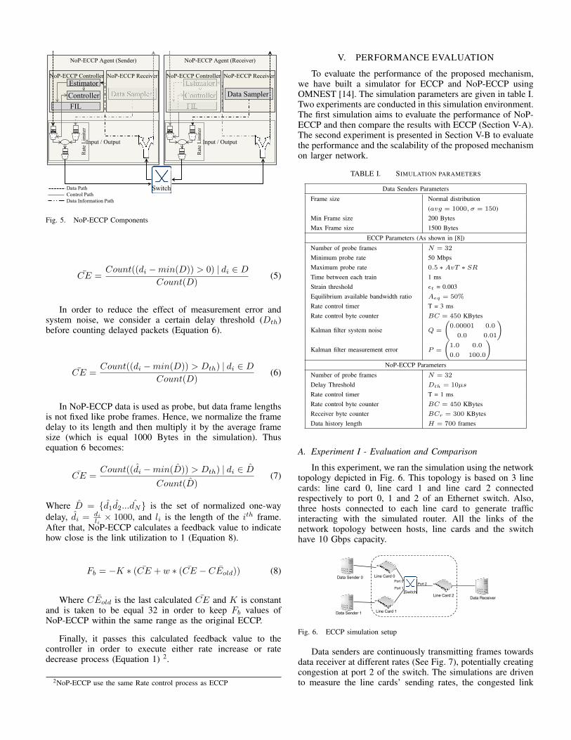
Unlike BART, the link utilization estimation technique,discussed in section III, does not require fixed inter-frameinterval and does not need to inject probe with rate higherthan AvBw. By eliminating these restrictions, we can usedata frames as probes. Yet, data frames need to be timestamped, which is impossible at the Ethernet layer (There isno field to add time stamp). In order to overcome this issue,we propose keeping track of the sending time, Frame CheckSequence (FCS) and frame length of the last H frames ina Frame Information List (FIL) at the sender side (Fig. 5).NoP-ECCP uses FCS and frame length pair as frame identifierbecause the possibility of having repeated FCS and framelength within H frames is very rare 1. In addition, ECCP isoriginally designed to be Ethernet protocol, consequently FCSwill not be changed as long as the frame remains within thesame Ethernet network. FIL length H is taken to be greaterthan the number of frames that can be sent while waitingfor data information acknowledge (H > (C ∗ T/L)), whereL is the average frame size and T is the time between twoacknowledges (H > 10 ∗ 109 ∗ 0.5 ∗ 10−3/(1000 ∗ 8) = 625).Fig. 5 depicts that NoP-ECCP does not use probe generatorwhich reduces the required computational power.
At the receiver side, NoP-ECCP data sampler samples thereceived data based on a byte counter BCr (Fig. 5). Thesampling Byte counter BCr is taken in the simulation to beequal 300 KB. Note that the sampling is based on byte counterinstead of timer, which achieves fairness by generating morefeedback messages for the high rate flows. Once this counterexpires, NoP-ECCP receiver sends the receiving time, FCSand frame length of the last N frames encapsulated in anEthernet frame to the sender line card (N is equal 32 in thesimulation). At the sender side, when NoP-ECCP estimatorreceives this information, it searches in the FIL for the sendingtime of each frame based on FCS and frame length. Then,it uses a simplified version of the previously introduced linkutilization estimation technique to calculate an estimation ofthe congestion (CE) as the percentage of packets that exceedthe minimum delay (Equation 5).
1Other fields in upper layer, like ID in layer 3 or sequence number in layer4, could be used as identifiers or alternatively source time stamp can be sentwith the packet as meta-data, for example as a header extension at the IPv6level, and the congestion estimation computation performed at the receiverinstead of at the sender as described in the paper.
Data Path Control Path Data Information Path
NoP-ECCP Agent (Sender)
NoP-ECCP Controller
Data Sampler
Input / Output
Rat
e Li
mite
r
Controller Estimator
FIL
NoP-ECCP Receiver
NoP-ECCP Agent (Receiver)
NoP-ECCP Receiver
Data Sampler
Input / Output
Rat
e Li
mite
r
Controller Estimator
FIL
NoP-ECCP Controller
Switch
Fig. 5. NoP-ECCP Components
CE =Count((di −min(D)) > 0) | di ∈ D
Count(D)(5)
In order to reduce the effect of measurement error andsystem noise, we consider a certain delay threshold (Dth)before counting delayed packets (Equation 6).
CE =Count((di −min(D)) > Dth) | di ∈ D
Count(D)(6)
In NoP-ECCP data is used as probe, but data frame lengthsis not fixed like probe frames. Hence, we normalize the framedelay to its length and then multiply it by the average framesize (which is equal 1000 Bytes in the simulation). Thusequation 6 becomes:
CE =Count((di −min(D)) > Dth) | di ∈ D
Count(D)(7)
Where D = {d1d2...dN} is the set of normalized one-waydelay, di = di
li× 1000, and li is the length of the ith frame.
After that, NoP-ECCP calculates a feedback value to indicatehow close is the link utilization to 1 (Equation 8).
Fb = −K ∗ (CE + w ∗ (CE − ¯CEold)) (8)
Where ¯CEold is the last calculated CE and K is constantand is taken to be equal 32 in order to keep Fb values ofNoP-ECCP within the same range as the original ECCP.
Finally, it passes this calculated feedback value to thecontroller in order to execute either rate increase or ratedecrease process (Equation 1) 2.
2NoP-ECCP use the same Rate control process as ECCP
V. PERFORMANCE EVALUATION
To evaluate the performance of the proposed mechanism,we have built a simulator for ECCP and NoP-ECCP usingOMNEST [14]. The simulation parameters are given in table I.Two experiments are conducted in this simulation environment.The first simulation aims to evaluate the performance of NoP-ECCP and then compare the results with ECCP (Section V-A).The second experiment is presented in Section V-B to evaluatethe performance and the scalability of the proposed mechanismon larger network.
TABLE I. SIMULATION PARAMETERS
Data Senders Parameters
Frame size Normal distribution(avg = 1000, σ = 150)
Min Frame size 200 BytesMax Frame size 1500 Bytes
ECCP Parameters (As shown in [8])
Number of probe frames N = 32
Minimum probe rate 50 MbpsMaximum probe rate 0.5 ∗ AvT ∗ SRTime between each train 1 msStrain threshold εt = 0.003Equilibrium available bandwidth ratio Aeq = 50%
Rate control timer T = 3 msRate control byte counter BC = 450 KBytes
Kalman filter system noise Q =
(0.00001 0.0
0.0 0.01
)
Kalman filter measurement error P =
(1.0 0.0
0.0 100.0
)NoP-ECCP Parameters
Number of probe frames N = 32
Delay Threshold Dth = 10µs
Rate control timer T = 1 msRate control byte counter BC = 450 KBytesReceiver byte counter BCr = 300 KBytesData history length H = 700 frames
A. Experiment I - Evaluation and Comparison
In this experiment, we ran the simulation using the networktopology depicted in Fig. 6. This topology is based on 3 linecards: line card 0, line card 1 and line card 2 connectedrespectively to port 0, 1 and 2 of an Ethernet switch. Also,three hosts connected to each line card to generate trafficinteracting with the simulated router. All the links of thenetwork topology between hosts, line cards and the switchhave 10 Gbps capacity.
Fig. 6. ECCP simulation setup
Data senders are continuously transmitting frames towardsdata receiver at different rates (See Fig. 7), potentially creatingcongestion at port 2 of the switch. The simulations are drivento measure the line cards’ sending rates, the congested link

Time (sec)0 1 2 3 4 5 6
Rate
(G
bps)
0
2
4
6
8
Data Sender 0
Data Sender 1
Fig. 7. Data Senders’ Desired Data Rates (DRs)
Time (sec)0 1 2 3 4 5 6
Rate
(G
bps)
0
2
4
6
8
LineCard 0
LineCard 1
(a) Line Cards’ Sending Rates (ECCP)
Time (sec)0 1 2 3 4 5 6
Rate
(G
bps)
0
2
4
6
8
LineCard 0
LineCard 1
(b) Line Cards’ Sending Rates (NoP-ECCP)
Fig. 8. Simulation Results (Sending Rates)
cross traffic, and the congested port queue length. Figures 8aand 8b depict the resulted sending rate at the output ports of theline cards for ECCP and NoP-ECCP respectively. The figuresshow that NoP-ECCP has a better performance in terms of ratestability and fairness. One can notice that at 1 < t < 2, NoP-ECCP does not throttle the sending rates because NoP-ECCPdoes not use any probe traffic which maximizes link utilizationand does not cause congestion in this period (Fig. 8b).
Fig. 9 depicts cross traffic rates. It shows that the crosstraffic controlled by ECCP within the congested period (t = 2sec : t = 5 sec) never reaches the maximum link capacity. Thislimitation meets the restriction of ECCP to keeping the crosstraffic around (100% − AvT ∗ Aeq) (95%) of the maximumlink capacity. While in NoP-ECCP, this restriction is no longerneeded and the cross traffic is equal to the maximum linkcapacity while having lower queue length (Fig. 10). Thus NoP-ECCP outperforms ECCP in terms of link utilization.
Fig. 9. Congested Link Cross Traffic
Fig. 10 shows the resulted queue length at the output queueof the congested port (port 2 in the switch). It shows thatNoP-ECCP outperforms ECCP in keeping the queue lengthclose to zero and eliminating the queue fluctuation. Thusdata experience minimum latency within NoP-ECCP system
Fig. 10. Congested Port Queue Length
boundaries.
B. Experiment II - Evaluation in a Larger Network
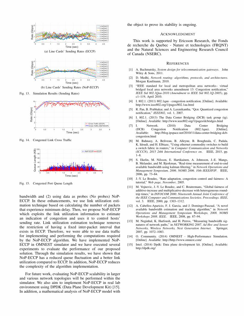
In order to test the scalability of NoP-ECCP, we ran thesimulation using a dumbbell topology of 8 hosts on eachside (Fig. 11). Furthermore, a comparison between NoP-ECCPand ECCP is presented while ECCP is modified to use probeinformation to estimate link utilization ( as in section III). Inthis simulation, data senders send data with rates shown in Fig.12 causing congestion between t = 0.5 sec and t = 3.5 sec.
Fig. 11. ECCP Simulation Network
Time (sec)0 0.5 1 1.5 2 2.5 3 3.5 4 4.5 5
Rate
(G
bps)
0
1
2
3Data Sender 0
Data Sender 1
Data Sender 2
Data Sender 3
Data Sender 4
Data Sender 5
Data Sender 6
Data Sender 7
Fig. 12. Data Senders’ Desired Data Rates DRs
Figures 13a and 13b show the sending rate at the outputports of the line cards for ECCP and NoP-ECCP respectively.The figures depict that both mechanisms succeeded in control-ling hosts’ sending rate. In addition, it shows that NoP-ECCPprovides better fairness and stable performance comparing toECCP.
Fig. 14 depicts the resulted cross traffic of the congestedlink. It shows that ECCP never reaches the maximum linkcapacity (which is its original objective to keep a percentageof link capacity available) while NoP-ECCP reaches the max-imum link utilization by eliminating the probes. Fig. 15 showsthe resulted queue length at the output queue of the congestedport. It shows that our proposed mechanism succeeds inkeeping the queue length close to zero and therefore dataexperience the minimum delay within NoP-ECCP boundaries.
VI. CONCLUSION
In this paper, we present several enhancements to ECCPnamely (1) estimating link utilization rather than available
(a) Line Cards’ Sending Rates (ECCP)
(b) Line Cards’ Sending Rates (NoP-ECCP)
Fig. 13. Simulation Results (Sending Rates)
Fig. 14. Congested Link Cross Traffic
Fig. 15. Congested Port Queue Length
bandwidth and (2) using data as probes (No probes) NoP-ECCP. In these enhancements, we use link utilization esti-mation technique based on calculating the number of packetsthat experience minimum delay. Then, we propose NoP-ECCPwhich exploits the link utilization information to estimatean indication of congestion and uses it to control hosts’sending rate. Link utilization estimation technique removesthe restriction of having a fixed inter-packet interval thatexists in ECCP. Therefore, we were able to use data trafficfor implementing and performing the computations requiredby the NoP-ECCP algorithm. We have implemented NoP-ECCP in OMNEST simulator and we have executed severalexperiments to evaluate the performance of our proposedsolution. Through the simulation results, we have shown thatNoP-ECCP has a reduced queue fluctuation and a better linkutilization compared to ECCP. In addition, NoP-ECCP reducesthe complexity of the algorithm implementation.
For future work, evaluating NoP-ECCP scalability in largerand various network topologies will be performed within thesimulator. We also aim to implement NoP-ECCP in real labenvironment using DPDK (Data Plane Development Kit) [15].In addition, a mathematical analysis of NoP-ECCP model with
the object to prove its stability is ongoing.
ACKNOWLEDGMENT
This work is supported by Ericsson Research, the Fondsde recherche du Quebec - Nature et technologies (FRQNT)and the Natural Sciences and Engineering Research Councilof Canada (NSERC).
REFERENCES
[1] A. Bachmutsky, System design for telecommunication gateways. JohnWiley & Sons, 2011.
[2] D. Medhi, Network routing: algorithms, protocols, and architectures.Morgan Kaufmann, 2010.
[3] “IEEE standard for local and metropolitan area networks– virtualbridged local area networks amendment 13: Congestion notification,”IEEE Std 802.1Qau-2010 (Amendment to IEEE Std 802.1Q-2005), pp.c1–119, April 2010.
[4] I. 802.1. (2011) 802.1qau - congestion notification. [Online]. Available:http://www.ieee802.org/1/pages/802.1au.html
[5] R. Pan, B. Prabhakar, and A. Laxmikantha, “Qcn: Quantized congestionnotification,” IEEE802, vol. 1, 2007.
[6] I. 802.1. (2013) The Data Center Bridging (DCB) task group (tg).[Online]. Available: http://www.ieee802.org/1/pages/dcbridges.html
[7] I. Network. (2010) Data Center Bridging(DCB) Congestion Notification (802.1qau). [Online].Available: http://blog.ipspace.net/2010/11/data-center-bridging-dcb-congestion.html
[8] M. Bahnasy, A. Beliveau, B. Alleyne, B. Boughzala, C. Padala,K. Idoudi, and H. Elbiaze, “Using ethernet commodity switches to builda switch fabric in routers,” in Computer Communication and Networks(ICCCN), 2015 24th International Conference on. IEEE, 2015, pp.1–8.
[9] S. Ekelin, M. Nilsson, E. Hartikainen, A. Johnsson, J.-E. Mangs,B. Melander, and M. Bjorkman, “Real-time measurement of end-to-endavailable bandwidth using kalman filtering,” in Network Operations andManagement Symposium, 2006. NOMS 2006. 10th IEEE/IFIP. IEEE,2006, pp. 73–84.
[10] J.-Y. Le Boudec, “Rate adaptation, congestion control and fairness: Atutorial,” Web page, November, 2005.
[11] M. Vojnovic, J.-Y. Le Boudec, and C. Boutremans, “Global fairness ofadditive-increase and multiplicative-decrease with heterogeneous round-trip times,” in INFOCOM 2000. Nineteenth Annual Joint Conference ofthe IEEE Computer and Communications Societies. Proceedings. IEEE,vol. 3. IEEE, 2000, pp. 1303–1312.
[12] A. Cabellos-Aparicio, F. J. Garcia, and J. Domingo-Pascual, “A novelavailable bandwidth estimation and tracking algorithm,” in NetworkOperations and Management Symposium Workshops, 2008. NOMSWorkshops 2008. IEEE. IEEE, 2008, pp. 87–94.
[13] M. Neginhal, K. Harfoush, and H. Perros, “Measuring bandwidth sig-natures of network paths,” in NETWORKING 2007. Ad Hoc and SensorNetworks, Wireless Networks, Next Generation Internet. Springer,2007, pp. 1072–1083.
[14] O. Community. (2014) OMNEST - High-Performance Simulation.[Online]. Available: http://http://www.omnest.com/
[15] Intel. (2014) Dpdk: Data plane development kit. [Online]. Available:http://dpdk.org/