printing - · pdf fileon october 3, 1996 with the new designation asme b16.47-1996. all...
TRANSCRIPT
61 6.47

~~
S T D * A S M E B L b D q 7 - E N G L 377b m 0757b70 0577357 778 m
The American Society of Mechanical Engineers
LARGE DIAMETER - - - --
STEEL FlANGES NPS 26 Through NPS 80
ASME B16.47-1916 (Revision of ASME 61 6.47-1 990)
Copyright by the American Society Of Mechanical Engineers Sat Jul 19 23:45:06 2003

S T D - A S M E BLbmq7-ENGL L77b 0757b70 0577LbU q7T H
Date of Issuance: January 31, 1997
The 1996 edition of this Standard is being issued with an automatic addenda subscription service. The use of an addenda allows revisions made in response to public review comments or committee actions to be published as necessary; revisions published in addenda will become effective 6 months after the Date of Issuance of the addenda. The next edition of this Standard is scheduled for publication in 2001.
ASME issues written replies to inquiries concerning interpretations of technical aspects of this Standard. The interpretations will be included with the above addenda service. Interpretations are not part of the addenda to the Standard.
ASME is the registered trademark of The American Society of Mechanical Engineers.
This code or standard was developed under procedures accredited as meeting the criteria for American National Standards. The Consensus Committee that approved the code or standard was balanced to assure that individuals from competent and concerned interests have had an opportunity to participate. The proposed code or standard was made available for public review and comment which provides an opportunity for additional public input from industry, academia, regulatory agencies, and the public-at-large.
ASME does not "approve," "rate," or "endorse" any item, construction, proprietary device, or activity.
ASME does not take any position with respect to the validity of any patent rights asserted in connection with any items mentioned in this document, and does not undertake to insure anyone utilizing a standard against liability for infringement of any applicable Letters Patent, nor assume any such liability. Users of a code or standard are expressly advised that determination of the validity of any such patent rights, and the risk of infringement of such rights, is entirely their own responsibility.
Participation by federal agency representative(s) or person(s) affiliated with industry is not to be interpreted as government or industry endorsement of this code or standard.
ASME accepts responsibility for only those interpretations issued in accordance with governing ASME procedures and policies which preclude the issuance of interpretations by individual volunteers.
No part of this document may be reproduced in any form, in an electronic retrieval system or otherwise,
without the prior written permission of the publisher.
The American Society of Mechanical Engineers 345 East 47th Street, New York, NY 10017
Copyright Q 1997 by THE AMERICAN SOCIETY OF MECHANICAL ENGINEERS
All Rights Reserved Printed in U.S.A.
Copyright by the American Society Of Mechanical Engineers Sat Jul 19 23:45:07 2003

STD-ASME BLb-97-ENGL L77b 0757b70 0579Lbl 32b m
FOREWORD
(This Foreword is not part of ASME 816.47-1996.)
In November, 1980, a task force was appointed within Subcommittee C of the American National Standards (ANSI) B16 Committee to develop a standard for pipe flanges in size NPS 26 through NPS 48. Every attempt was made to standardize those dimensions that existed within the industry for the materials covered by ANSI B16.5.
Prompted by suggestions received from committee members, the task force was authorized to increase the size range to NPS 60. The first draft was developed in December 1982 to include Class 75 through Class 1500 for the size range NPS 26 through NPS 60. Flange dimensions were based on the Manufacturers Standardization Society Standard Practice (MSS SP) 44 flanges except for Class 75 flanges which are ANSUAPI 605 flanges.
At the request of the American Petroleum Institute (API), flange dimensions in accordance with the API Standard 605 were included in the subsequent drafts. Class 1500 flanges were deleted due to lack of interest in using large size flanges in that pressure-temperature rating.
The API-605 flanges for Classes 150 and 300 and for sizes NPS 36 and smaller for classes higher than Class 300 are not compatible with the MSS SP-44 flanges. Thus, the MSS SP-44 flanges are designated as Series A flanges and the API-605 flanges are designated as Series B flanges in this Standard. Materials covered in this Standard are as in ANSI B 16.5 except nickel base alloys are excluded. Pressure-temperature ratings are in accordance with ANSI B16.5.
In 1982, American National Standards Committee B16 was reorganized as the American Society of Mechanical Engineers (ASME) B 16 Committee operating under procedures accredited by ANSI. Following approval by the Standards Committee and ASME, approval as an American National Standard was given by ANSI on June 12, 1990.
This 1996 Edition allows flanges marked with more than one material grade or specification, revises flange facing finish requirements, has revised pressure-temperature ratings for several material groups, adds permissible flange facing imperfections, adds blind flanges for Series B flanges, and includes several other revisions. Following approval by the Standards Committee and ASME, approval as an American National Standard was given by ANSI on October 3, 1996 with the new designation ASME B16.47-1996.
All requests for interpretations or suggestions for revisions should be sent to the Administra- tive Secretary B 16, The American Society of Mechanical Engineers, United Engineering Center, 345 East 47th Street, New York, NY 10017.
... 111
Copyright by the American Society Of Mechanical Engineers Sat Jul 19 23:45:08 2003

ASME B16 Committee Standardization of Valves, Flanges, Fittings, Gaskets, and Valve
Actuators
(The following is a roster of the Committee at the time of approval of this Standard.)
OFFICERS
W. N. McLean, Chair R. A. Schmidt, Vice Chair K. M. Ciciora, Secretary
COMMITTEE PERSONNEL
W. L. Ballis, Columbia Gas Distribution Co., Columbus, Ohio R. R. Brodin, Fisher Controls International, Inc., Marshalltown, Iowa M. A. Clark, Nibco Inc., Elkhart, Indiana A. Cohen, Copper Development Association, Inc., New York, New York W. C. Farrell, Jr., Consultant, Birmingham, Alabama C. E. Floren, Mueller Co., Decatur, Illinois D. R. Frikken, Monsanto Co., St. Louis, Missouri M. W. Garland, Frick Co., Waynesboro, Pennsylvania J. C. Inch. Mueller Refrigeration Products Co., Hartsville, Tennessee 0. A. Jolly, The Henry Vogt Machine Co., Louisville, Kentucky W. G. Knecht, Consultant, Williamsport, Pennsylvania R. A. Koester, The William Powell Co., Cincinnati, Ohio W. N. McLean, Newco Valve Co., Palos Park, Illinois M. L. Nayyar, Bechtel Corp., Gaithersburg, Maryland R. A. Schmidt, Ladish Co., Russellville, Arkansas W. M. Stephan, Flexitallic Inc., Pennsauken, New Jersey T. F. Stroud, Ductile Iron Research Association, Birmingham, Alabama M. D. Wasicek, ABS Americas, Houston, Texas A. E. White, Richard E. White b Associates, South Bend, Indiana D. A. Williams, Southern Company Services, Birmingham, Alabama L. A. Willis, Dow Chemical Co., Freeport, Texas W. R. Worley, Union Carbide Corp., South Charleston, West Virginia
PERSONNEL OF SUBCOMMITTEE C - STEEL FLANGES AND FLANGED FllTlNGS
D. R. Frikken, Chair, Monsanto Co., St. Louis, Missouri K. M. Ciciora, Secretary, ASME lnternationai, New York, New York V. C. Bhasin, Sigmatech, Pittsburgh, Pennsylvania G. D. Conlee, Consultant, St. Louis, Missouri W. C. Farrell, Jr., Consultant, Birmingham, Alabama M. L. Henderson, Coffer Corp., Houston, Texas R. E. Johnson, Flowline Div., New Castle, Pennsylvania R. Koester, The William Powell Co., Cincinnati, Ohio R. Madewell, Flo-Bend Inc., Sand Springs, Oklahoma W. N. McLean, Newco Valve Co., Palos Park, Illinois
V
Copyright by the American Society Of Mechanical Engineers Sat Jul 19 23:45:09 2003
M. L Nayyar, Bechtel Corp., Gaithersburg, Maryland R. A. Schmidt, Ladish Co., Russellville, Arkansas D. I.. Shira, Taylor Forge, Cordova, Tennessee J. C. Thompson, Milwaukee Valve, Rising Sun, Maryland L. A. Willis, Dow Chemical Co., Freeport, Texas
vi
Copyright by the American Society Of Mechanical Engineers Sat Jul 19 23:45:11 2003
11”
OP 6E 8E LE 9E SE PE O€ 62 I 1 01 8
EE
EE
EE
ZE
ZE
1E
I €
A
!!!
................................. sa%uqd 8 s a y s 0 s ~ s s q 3 30 suo!suama 1 1 sa%utz~,~ g s a p s FL ssq3 30 suorsuama 01
sa8uqd y s a u a ~ 009 s s q 3 30 suo!suam!a 8 sa%wld v sauas mp s s q 3 30 suo!suaur!a L saBua1d v sauag s s q 3 30 suo!suauna 9 sa%uqd v sauas 051 s s q 3 30 s u o y a u n a s
suo!ppuauwoDaa puo!suaw!a %u!i108 a 8 q d p s%u!xd iu!oy-%u!X 30 suo!suauna E
z suo!ie3ypadg Bug~og 30 i s g HI
SuO~l~3y!3dS I ~ ! . W ~ ~ 30 IS!? VI
..................................
................................. Sa%UE1+J V SaUaS 006 S S E l 3 JO SUO!SUaW!a 6 .................................
.................................
.................................
.................................
..............................
..........................................
. . . . . . . . . . sls!~aiqq 8.z y8no.q 1’1 sdno13 lo3 s8u!pX alnleJaduIaL-aJnssaq
..............................................
............................................. W W l
...................................................................... 1s3.L 8 ................................................................ sa3umaIoL L
suo!suaru!a g S I y J 3 1 q q 5 % u ! v w P
=Is E s%u!iaX aJIIltrJaduIaL-3JnSSaId z
ado3s I
...............................................................
.................................................................
..................................................................
......................................................................
..............................................
....................................................................
...................................................... JalSOX aallFUl03 SplepUrrlS PJOMaOd .......................................................................
SlN31N03

12 Dimensions of Class 300 Series B Flanges ................................. 41 13 Dimensions of Class 400 Series B Flanges ................................. 42 14 Dimensions of Class 600 Series B Flanges ................................. 43
16 Permissible Imperfections in Flange Facing Finish .......................... 46 15 Dimensions of Class 900 Series B Flanges ................................. 44
Annexes
B Gaskets (Other Than Ring-Joint) ........................................... 51 C Method for Calculating Bolt Lengths ....................................... 53 D Quality System Program ................................................... 55 E References ................................................................ 57
A Methods for Establishing Pressure-Temperature Ratings ..................... 47
Figures B1 Gasket Groups and Typical Materials ....................................... 52 C1 Specified Stud-Bolt Length ................................................ 53
Tables A1 Rating Ceiling Values ..................................................... 49 C1 F Values ................................................................. 53 C2 n Values .................................................................. 53
Interpretations ............................................................... 61
viii
Copyright by the American Society Of Mechanical Engineers Sat Jul 19 23:45:13 2003
~
S T D - A S M E BLb.47-ENGL L99b 0759b70 0579Lbb 908
ASME 816.47-1996
LARGE DIAMETER STEEL FLANGES
1 SCOPE
1.1 General
This Standard covers pressure-temperature ratings, materials, dimensions, tolerances, marking, and testing for pipe flanges in sizes NPS 26 through N P S 60 and in ratings Classes 75, 150, 300, 400, 600, and 900. Flanges may be cast, forged, or plate (for blind flanges only) materials, as listed in Table 1A.
Requirements and recommendations regarding bolting and gaskets are also included.
1.2 Flange Series
This Standard provides two series of flange dimen- sions. Series A specifies flange dimensions for general use flanges. Series B specifies flange dimensions for compact flanges which, in general, have smaller bolt circle diameters than Series A flanges. These two series of flanges are not interchangeable. The user should recognize that some flanged valves, equipment bolted between flanges, and flanged equipment may only be compatible with bolt circle diameter of one series of flanges.
1.3 References
1.3.1 Referenced Standards. Standards and spec- ifications adopted by reference in this Standard are shown in Annex E, which is part of this Standard. It is not considered practical to identify the specific edition of each standard and specification in the individual references. Instead, the specific edition reference is identified in Annex E. A flange manufactured in accord- ance with earlier editions of the referenced standards, and in all other respects conforming to this Standard, will be considered to be in conformance with this Standard.
1.3.2 Codes and Regulations. A flange used under the jurisdiction of the ASME Boiler and Pressure Vessel Code (ASME BPV Code), the ASME Code for Pressure Piping, or a governmental regulation is subject to any limitation of that code or regulation. This includes any maximum temperature limitation, rule governing the use of a material at low temperature, or provisions
for operation at a pressure exceeding the pressure- temperature ratings in this Standard.
1.4 Applicable Ratings
The pressure-temperature ratings in this Standard are applicable upon its publication to all flanges within its scope which otherwise meet its requirements. For unused flanges maintained in inventory, the manufacturer of the flange may certify conformance to this Edition, provided he can demonstrate that all requirements of this Edition have been met. Where such components were installed in accordance with the pressure-tempera- ture ratings of an earlier edition of this Standard, those ratings are applicable, except as may be governed by the applicable code or regulation (see para. 1.3.2).
1.5 User Accountability
This Standard cites duties and responsibilities that are to be assumed by the user in the areas of application, installation, hydrostatic testing, operation, and material selection.
1.6 Quality Systems
Nonmandatory requirements relating to the product manufacturer’s Quality System Program are described in Annex D.
2 PRESSURE-TEMPERATURE RATINGS
2.1 Rating Basis
Ratings are maximum allowable working gage pres- sures, at the temperatures shown in Table 2 for the applicable material and rating. For intermediate tempera- tures, linear interpolation is permitted. See Annex A, which is part of this Standard, for methods of establish- ing pressure-temperature ratings.
2.2 Ratings of Flanged Joints
A flanged joint is composed of three separate and independent, although interrelated, components: the flanges, the gasket, and the bolting, which are assembled by yet another influence, the assembler. Proper controls must be exercised in the selection and application for
1
Copyright by the American Society Of Mechanical Engineers Sat Jul 19 23:45:14 2003

ASME 816.47-1996
all these elements in order to attain a joint which has acceptable leak tightness. Special techniques such as controlled bolt tightening may be necessary to achieve a tight joint in service.
Ratings in this Standard apply to flanged joints which conform to the limitations on bolting in para. 5.3 and on gaskets in para. 5.4, and which are made up in accordance with good practice for alignment and assem- bly. See also para. 2.4. Use of the ratings for flanged joints not conforming to these limitations is the sole responsibility of the user. Requirements for alignment and assembly of joints are not given in this Standard.
If the two flanges in a flanged joint do not have the same pressure-temperature ratings, the rating of the joint at any temperature is the lower of the two flange ratings at that temperature.
2.3 Rating Temperature
The temperature shown for a corresponding pressure rating is the temperature of the pressure containing shell of the flange. In general, this temperature is the same as that of the contained fluid. Use of a pressure rating corresponding to a temperature other than that of the contained fluid is the responsibility of the user, subject to the requirements of the applicable code or regulation. For any temperature below -20°F the rating shall be no greater than the rating shown for -20°F.
2.4 Temperature Considerations
Application of the ratings in this Standard to flanged joints both high and low temperatures shall take into consideration the risk of leakage due to forces and moments developed in the connected piping or equip- ment. The following provisions are intended to minimize these risks.
2.4.1 High Temperature Service. At tempera- tures in the creep range, gradual relaxation of flanges, bolts, and gaskets may progressively reduce bolt loads. It may be necessary to arrange for -periodic tightening of bolts to prevent leakage. Joints subject to substantial thermal gradients may require the same attention.
When used above 400°F, Classes 75 and 150 flanged joints may develop leakage unless care is taken to avoid imposing severe external loads andor severe thermal gradients. For other classes, similar consider- ation should be given above 750 F.
LARGE DIAMETER STEEL FLANGES
2.4.2 Low Temperature Service. Some of the materials listed in the rating tables undergo sufficient decrease in toughness at low temperatures that they cannot safely sustain shock loadings, sudden changes of stress or temperature, or high stress concentrations.
2.5 System Hydrostatic Test
Flanged joints may be subjected to system hydrostatic tests at a pressure not to exceed 1.5 times the 100°F rating rounded off to the next higher 25 psi.
Testing at any higher pressure is the responsibility of the user, subject to the requirements of the applicable code or regulation.
2.6 Welding Neck Flanges
Ratings for carbon steel cylindrically bored welding neck flanges covered by this Standard are based upon their hubs at the welding end having a thickness at least equal to that calculated for pipe having 40.0 ksi specified minimum yield strength. The ratings also apply to such flanges used with components of unequal strength and unequal wall thickness when the attachment welds is made in accordance with the applicable code or regulation. See Figs. 5, 6, and 7.
2.7 Multiple Material Grades
Materials for flanges may meet the requirements for more than one specification or grade of a specification listed in Table 1A. In that event, the pressure-tempera- ture ratings for any of these specifications or grades may be used provided that the marking is in accordance with para. 4.1.2(d).
3 SIZE
3.1 Nominal Size
The size of a flange covered by this Standard is its nominal pipe size (NPS). The diameter of a bolt is its nominal size. Use of nominal indicates that the stated size or dimension is only for designation, not measure- ment. The actual dimension may or may not be the nominal size and is subject to established tolerances.
4 MARKING
4.1 General
Except as modified herein, flanges shall be marked as required in MSS SP-25.
Copyright by the American Society Of Mechanical Engineers Sat Jul 19 23:45:15 2003

~
STD-ASME BLb.47-ENGL L77b H 0757b70 0579Lb8 780
LARGE DIAMETER STEEL FLANGES
4.1.1 Name. The manufacturer's name or trademark shall be applied.
4.1.2 Materials (a) Cast flanges shall be marked with the ASTM
specification', grade identification symbol, and the melt number identification or melt identification.
(b) Plate flanges and forged flanges shall be marked with the ASTM specification number and grade identifi- cation symbol.
(c) A manufacturer may supplement these mandatory material indications with his trade designation for the material grade, but confusion of symbols shall be avoided.
(d) Flanges manufactured from material which meets the requirements for more than one specification or grade of a specification listed in Table 1A may be marked with more than one of the applicable specifica- tion or grade symbols. The symbols shall be placed to avoid confusion in identification.
4.1.3 Rating Class. The marking shall be the appli- cable pressure rating class: 75 (Series B only), 150, 300, 400, 600, or 900.
4.1.4 Designation. The designation of Series A B16/A for flange dimensions in accordance with Tables 5 through 9 and Series B B16/B for flange dimensions in accordance with Tables 10 through 15 shall be applied, preferably located adjacent to the class designa- tion, to indicate conformance to this Standard.
4.1.5 Temperature. No temperature markings are required on flanges, but if marked, the temperature shall be shown with its corresponding tabulated pressure rating for the material.
4.1.6 Size. The nominal pipe size shall be given.
4.1.7 Ring-Joint Flange. The edge (periphery) of each ring-joint flange shall be marked with the letter "R" and the corresponding ring-groove number.
5 MATERIALS
5.1 General
Flanges covered by this Standard shall be castings, forgings, and (for blind flanges only) plate, as listed in Table 1A. Recommended bolting materials are listed
' The ASME Boiler and Pressure Vessel Code, Section 11 specification number may be substituted provided the material is covered by Section 11.
ASME B16.47-1996
in Table 1B. (See also para. 5.3.) The ASME Boiler and Pressure Vessel Code, Section I1 materials, which also meet the requirements of the specifications listed in Table 1. may also be used.
5.1.1 Application. Criteria for the selection of ma- terials are not within the scope of this Standard. The possibility of material deterioration in service should be considered by the user. Carbide phase conversion to graphite and excessive oxidation of femtic materials or susceptibility to intergranular corrosion of austenitic materials are among those items requiring attention. A detailed discussion of precautionary considerations can be found in Appendix F of ASME B31.3.
5.1.2 Toughness. Some of the materials listed in Table 1A undergo a decrease in toughness when used at low temperatures, to the extent that codes referencing this Standard may require impact tests for applications even at temperatures higher than i20"F. It is the responsibility of the user to assure that such testing is performed.
5.1.3 Responsibility. When service conditions dic- tate the implementation of special material requirements, e.g., using a Group 2 material above 1000"F, it is the user's responsibility to so specify to the manufacturer in order to ensure compliance with metallurgical require- ments listed in the notes in Table 2.
5.2 Mechanical Properties
Mechanical properties shall be obtained from test specimens that represent the final heat-treated condition of the material.
5.3 Bolting
Bolting listed in Table 1B is recommended for use in flange joints covered by this Standard. Bolting of other material may be used if permitted by the applicable code or governmental regulation. All bolting materials are subject to the following limitations.
5.3.1 High Strength Bolting. Bolting materials having allowable stresses not less than those for ASTM A 193 Gr. B7 are listed as high strength in Table 1B. These and other materials of comparable strength may be used in any flanged joint.
5.3.2 Intermediate Strength Bolting. Bolting materials listed as intermediate strength in Table lB, and other bolting of comparable strength, may be used in any flanged joint, provided the user verifies their
3
Copyright by the American Society Of Mechanical Engineers Sat Jul 19 23:45:16 2003

~
STD-ASME B L b - 9 7 - E N G L 1 9 9 b W 0759b70 0577Lb7 b L 7
ASME 816.47-1996
ability to seat the selected gasket and to maintain a sealed joint under expected operating conditions.
5.3.3 Low Strength Bolting. Bolting materials having not more than 30 ksi specified minimum yield strength are listed as low strength in Table 1B. These materials and others of comparable strength shall be used only in Classes 75, 150, and 300 joints, and only with gaskets described in para. 5.4.1. Flanged joints using low strength carbon steel bolts shall not be used above 400°F or below -20°F.
5.3.4 Bolting to Gray Cast Iron Flanges. The following recommendations are made in recognition of the low ductility of gray cast iron.
(n ) Where Class 150 steel flanges are bolted to Class 125 cast iron flanges, the gaskets should be made of Group Ia materials, the steel flanges should have flat faces, and:
(I) low strength bolting within the limitations of para. 5.3.3 should be used with ring gaskets extending to the bolt holes; or
(2) bolting of low (para. 5.3.3), intermediate (para. 5.3.2), or high (para. 5.3.1) strength may be used with full face gaskets extending to the outside diameters of the flanges.
(b) Where Class 300 steel flanges are bolted to Class 250 cast iron flanges, the gaskets should be made of Group Ia materials and:
(I) low strength bolting within the limitations of para. 5.3.3 should be used with gaskets extending to the bolt holes and with flanges having either raised or flat faces; or
(2) bolting of low (para. 5.3.3), intermediate (para. 5.3.2), or high (para. 5.3.1) strength may be used with full face gaskets extending to the outside diameters of the flanges and with both the Class 300 steel and Class 250 cast iron flanges having flat faces.
(c) Alignment of flange faces is essential along with control of assembly bolt torque so as not to over-stress the cast iron flanges. Care must also be exercised to ensure that piping loads transmitted to cast iron flanges are controlled taking into account its lack of ductility and recognizing that cast iron flanges should not be used where suddenly applied loads such as rapid pressure fluctuations may occur.
5.4 Gaskets
Ring-joint gasket materials shall conform to ASME B16.20. Materials for other gaskets are described in Annex B, which is part of this Standard. The user is responsible for selection of gasket materials which will
LARGE DIAMETER STEEL FLANGES
withstand the expected bolt loading without injurious crushing, and which are suitable for the service condi- tions. Particular attention should be given to gasket selection if a system hydrostatic test approaches the test pressure specified in para. 2.5.
5.4.1 Gaskets for Low Strength Bolting. If bolting listed as low strength in Table 1B is used, gaskets shown in Annex B, Fig. B1, Group Ia, shall be used.
5.4.2 Gaskets for Class 150 Flanged Joints. It is recommended that only Fig. B1, Group Ia or Ib gaskets be used for Class 150 flanged joints.
5.4.3 Gaskets for Class 75 Flanged Joints. It is recommended that only Group Ia gaskets with a gasket factor m = 2 or less, and minimum design seating stress y = 1600 psi or less, be used. The m and y factors are those given in Table 2-5.1, Appendix 2 of the ASME Boiler and Pressure Vessel Code, Section VIII, Division 1.
6 DIMENSIONS
6.1 Facings
6.1.1 General. Classes 75, 150, and 300 flanges are regularly furnished with a 0.06 in. raised face, which is included in the minimum flange thickness C. Classes 400,600, and 900 flanges are regularly furnished with 0.25 in. raised face, which is additional to the minimum flange thickness C. It is recommended that the Class 75 flanges be used only with a 0.06 in. raised face or flat face.
Dimensions for ring-joint facing are given in Table 3 for Series A flanges. Any other facing than the above, when required for any class, shall be furnished as follows.
6.1.1.1 In the case of the 0.25 in. raised face for Classes 150 and 300, the minimum flange thickness C shall first be provided and then the raised face shall be added thereto.
6.1.1.2 With ring-joint, the minimum flange thickness shall first be provided and then sufficient metal added thereto so that the bottom of the ring- joint groove is in the same plane as the flange edge of a full thickness flange.
4
Copyright by the American Society Of Mechanical Engineers Sat Jul 19 23:45:17 2003

LARGE DIAMETER STEEL FLANGES
6.1.2 Blind Flanges. Blind flanges need not be faced in the center if, when this center part is raised, its diameter is at least 1 in. smaller than the inside diameter of the mating flange. When the center part is depressed, its diameter shall not be greater than the inside diameter of the mating flange. Machining of the depressed center is not required.
6.1,3 Flat Face Flanges. This Standard permits flat face flanges in all classes, either by providing flanges having the full thickness or the thickness with the raised face removed, without reduction of the pressure-temperature ratings subject to the following provisions.
6.1.3.1 The thickness of a Class 75, 150, or 300 flange from which the raised face has been removed shall be no less than the applicable C dimension of Tables 5, 6, 10, 11, and 12, minus 0.06 in.
6.1.3.2 The thickness of a flange of Class 400 or higher from which the raised face has been removed shall be no less than the applicable C dimension of Tables 7 to 9 and 13 to 15.
6.1.3.3 A gasket of Group Ia material in Annex B, Fig. B1, is recommended for all joints having two flat faced flanges using a gasket which has a larger diameter than those of the raised face.
6.1.3.4 The flange facing shall conform with para. 6.1.4 for the full width of seating of the gasket.
6.1.4 Flange Facing Finish. The finish of contact faces of pipe flanges shall be judged by visual compari- son with Ra Standards (see ANSVASME B46.1) and not by instruments having stylus tracers and electronic amplification. The finishes required are given below. Other finishes may be furnished by agreement between user and manufacturer.
6.1.4.1 Ring-Joint. The side wall surface to gasket groove shall not exceed 63 pin. roughness.
6.1.4.2 Other Flange Facings. Either a serrated concentric or serrated spiral finish having a resultant surface finish from 125 kin. to 250 pin. average roughness shall be furnished. The cutting tool employed should have an approximate 0.06 in. or larger radius, and there should be from 45 grooves/in. through 55 groovedin.
6.1.5 Flange Facing Finish Imperfections. Im- perfections in the flange facing finish shall not exceed the dimensions shown in Table 16. Adjacent imperfec- tions shall be separated by a distance of at least four
c
S T D - A S M E BLb.97-ENGL 397b 0757b70 0577370 337
J
ASME B 16.47- 1996
times the maximum radial projection. A radial projection shall be measured by the difference between an outer radius and an inner radius encompassing the imperfec- tion where the radii are struck from the centerline of the bore. Imperfections less than half the depth of the serrations shall not be considered cause for rejection. Protrusions above the serrations are not permitted.
6.2 Flange Bolt Holes
Bolt holes are in multiples of four. Bolt holes shall be equally spaced.
6.3 Spot Facing
All cast and forged steel flanges shall have bearing surfaces for bolting which shall be parallel to the flange face within 1 deg. Any back facing or spot facing required to accomplish parallelism shall not reduce the flange thickness C below the dimensions given in Tables 5 through 15. Any spot facing or back facing shall be in accordance with MSS SP-9.
6.4 Welding End Preparation for Welding Neck Flanges
6.4.1 Welding ends are shown in Figs. 1 through 7.
6.4.2 The contours of the outside of the welding neck beyond the welding groove are shown in Figs. 1, 2, 5 , and 7.
6.4.3 Straight through bores shown in Figs. 1 and 2 are standard unless otherwise specifically ordered to suit the special conditions illustrated in Figs. 3, 4, 6, and 7.
6.4.4 Other welding end preparations furnished by agreement between purchaser and manufacturer do not invalidate compliance with this Standard.
6.5 Flange Bolting Dimensions
6.5.1 Stud-bolts threaded at both ends or full length, or bolts with hexagonal heads may be used. Dimensional recommendations for bolts, stud-bolts, and nuts are shown in Table 4. See para. 5.3 for bolting material.
6.5.2 For the method of calculating bolt lengths, see Annex C. The method of calculating bolt length is established for the convenience of industry to simplify the assembly of these parts on construction work, but
Copyright by the American Society Of Mechanical Engineers Sat Jul 19 23:45:18 2003
STDmASHE BLb-97-ENGL L77b 0757b70 0577373 275
ASME B16.47-1996
users may select combinations of these bolt lengths to suit their needs. Hence, Annex C is not considered part of this standard.
6.6 Gaskets for Line Flanges
6.6.1 Ring-joint gasket dimensions shall conform to ASME B16.20.
6.6.2 Nonmetallic gasket dimensions for Series A flanges with raised face shall conform to ASME B 16.21.
6.6.3 Solid flat metal gaskets shall have contact width not greater than for Group I11 gaskets.
6.6.4 Spiral wound and double-jacketed corrugated metal gasket shall conform to ASME B16.20.
6.6.5 Nonmetallic gasket dimensions for Series B flanges with raised face shall have outside diameter equal to the raised face diameter and inside diameter equal to the nominal pipe size. If self-centering ring gaskets are used, the outside diameter shall equal the bolt circle diameter less one bolt hole diameter.
7 TOLERANCES~
7.1 General
For the purposes of determining conformance with this Standard, the convention for fixing significant digits where limits, maximum or minimum values are speci- fied, shall be the rounding-off method defined in ASTM Practice E29. This requires that an observed or calcu- lated value shall be rounded to the nearest unit in the last right-hand digit used for expressing the limit.
The listing of decimal tolerances does not imply a particular method of measurement.
7.2 Facings
7.2.1 Outside diameter, 0.06 in. raised face, 0.08 in.
7.2.2 Outside diameter, 0.25 in. raised face, 0.04 in.
7.2.3 Ring-joint groove tolerances are shown in Table 3.
LARGE DIAMETER STEEL FLANGES
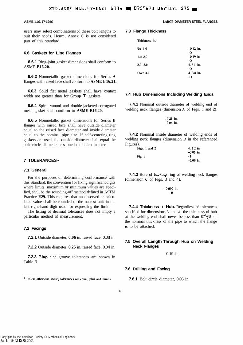
7.3 Flange Thickness
Thickness, in.
To 1.0
1 .o-2.0
2.0-3.0
Over 3.0
4.12 in. -0 4.19 in. -0 4 . 3 1 in. -0 4 . 3 8 in. -0
7.4 Hub Dimensions Including Welding Ends
7.4.1 Nominal outside diameter of welding end of welding neck flanges (dimension A of Figs. 1 and 2).
4 . 2 1 in. -0.06 in.
7.4.2 Nominal inside diameter of welding ends of welding neck flanges (dimension B in the referenced Figures).
Figs. 1 and 2 4 . 1 2 in. -0.06 in.
-0.06 in. Fig. 3 4
7.4.3 Bore of backing ring of welding neck flanges (dimension C of Figs. 3 and 4).
+0.010 in. -0
7.4.4 Thickness of Hub. Regardless of tolerances specified for dimensions A and B, the thickness of hub at the welding end shall never be less than 87v2% of the nominal thickness of the pipe to which the flange is to be attached.
7.5 Overall Length Through Hub on Welding Neck Flanges
0.19 in.
7.6 Drilling and Facing
* Unless otherwise stated, tolerances are equal, plus and minus. 7.6.1 Bolt circle diameter, 0.06 in.
6
Copyright by the American Society Of Mechanical Engineers Sat Jul 19 23:45:20 2003
STDOASME BLb.LI7-ENGL L77b E 0757b70 0577372 1171
ASME 616.47-1996 LARGE DIAMETER STEEL FLANGES
7.6.2 Center-to-center of adjacent bolt holes, 0.03 in.
7.6.3 Eccentricity between bolt circle diameter and machined facing diameters, 0.06 in.
8 TEST
8.1 Flange Testing
Flanges are not required to be hydrostatically tested.
7
Copyright by the American Society Of Mechanical Engineers Sat Jul 19 23:45:21 2003
STD-ASME BLb.47-ENGL L77b 0757b70 05771173 048 H
1.2
1.3
1.4
ASME 816.47-1996 LARGE DIAMETER STEEL FLANGES
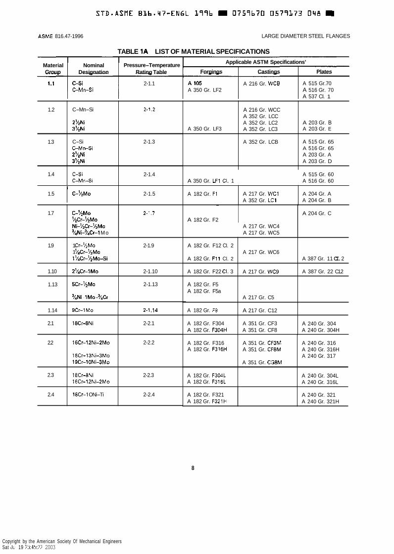
TABLE 1A LIST OF MATERIAL SPECIFICATIONS
C-Mn-Si 2-7.2
2’/2Ni 3’4Ni
C-Si 2-1.3 CMn-Si 21/2Ni 3 ’ / 2 ~ i
C S i 2-1.4 C-MnSi
Material Nominal Pressure-Temperature Group Designation Rating Table
2-1.1 C-Mn-Si
A 350 Gr. LF3
A 216 Gr. WCC A 352 Gr. LCC A 352 Gr. LC2 A 352 Gr. LC3
A 352 Gr. LCB
A 203 Gr. B A 203 Gr. E
A 515 Gr. 65 A 516 Gr. 65 A 203 Gr. A A 203 Gr. D
1.5 I C-’/2Mo 2-1.5
2-1.7
A 182 Gr. F1 A 217 Gr. WCl A 352 Gr. LC1
A 204 Gr. A A 204 Gr. B
1.7 C-Y~MO ’/2Cr-’/2M0 Ni-’/&r-’/2Mo 3/4Ni-3/4Cr-1 Mo
Applicable ASTM Specifications’
Forgings Castings Plates
A 515 Gr.70 A 516 Gr. 70 A 537 CI. 1
A 216 Gr. WCB A 350 Gr. LF2
1.9
1.10
1.13
1 Cr-V’Mo 2-1.9 1 ’/‘Cr-’/2Mo 1’/4Cr-’/2Mo-Si
2’/,Cr-IMo 2-1.10
5Cr-’/2Mo 2-1.13
y4Ni-1 MO-~/~C~
A 350 Gr. LF1 CI. 1
A 182 Gr. F12 CI. 2
A 182 Gr. F11 CI. 2
A 182 Gr. F22 CI. 3
A 182 Gr. F5 A 182 Gr. F5a
A 182 Gr. F9
A 182 Gr. F304 A 182 Gr. F304H
A 515 Gr. 60 A 516 Gr. 60
A 217 Gr. WC6 A 387 Gr. 11 CI. 2
A 387 Gr. 22 C1.2 A 217 Gr. WC9
A 217 Gr. C5
A 217 Gr. C12
A 351 Gr. CF3 A 351 Gr. CF8
A 240 Gr. 304 A 240 Gr. 304H
1.14
2.1
2.2
2.3
~
A 182 Gr. F2
~
9Cr-1Mo 2-1.14
18Cr-8Ni 2-2.1
16Cr-12Ni-2Mo 2-2.2
18Cr-13Ni-3Mo 19Cr-1ONi-3Mo
18Cr-8Ni 2-2.3 16Cr-12Ni-2Mo
A 217 Gr. WC4 A 217 Gr. WC5
A 182 Gr. F316 A 182 Gr. F316H
A 182 Gr. F304L A 182 Gr. F316L
A 204 Gr. C
A 351 Gr. CF3M A 351 Gr. CF8M
A 351 Gr. CG8M
A 240 Gr. 316 A 240 Gr. 316H A 240 Gr. 317
A 240 Gr. 304L A 240 Gr. 316L
2.4 18Cr-1 ONi-Ti 2-2.4 A 182 Gr. F321 A 182 Gr. F321H
8
~~
A 240 Gr. 321 A 240 Gr. 321H
Copyright by the American Society Of Mechanical Engineers Sat Jul 19 23:45:22 2003
LARGE DIAMETER STEEL FLANGES ASME B16.47- 1996
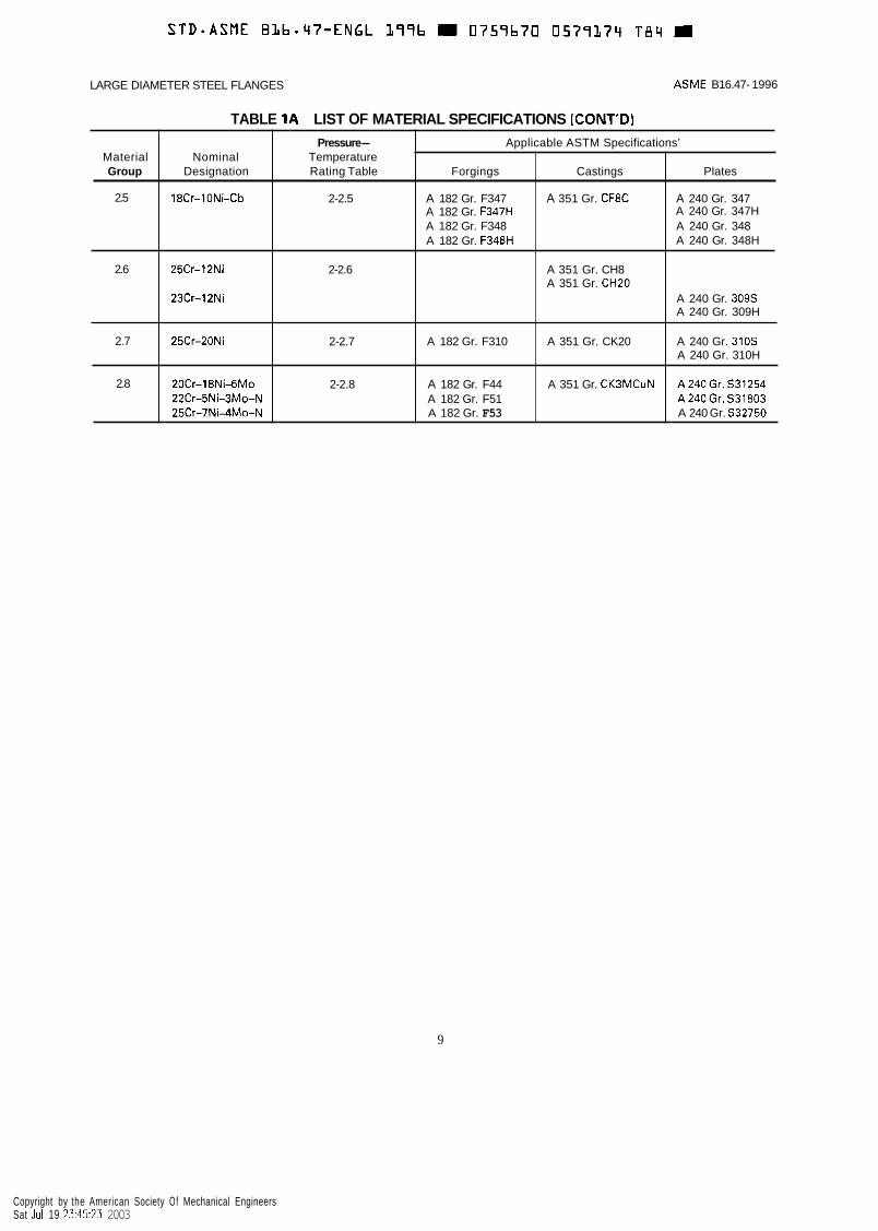
TABLE 1A LIST OF MATERIAL SPECIFICATIONS (CONT’D)
Material Group
2.5
2.6
2.7
2.8
Pressure- Applicable ASTM Specifications’ Nominal Temperature
Designation Rating Table Forgings Castings Plates
18Cr-1ONi-Cb 2-2.5 A 182 Gr. F347 A 351 Gr. CF8C A 240 Gr. 347 A 240 Gr. 347H A 240 Gr. 348 A 240 Gr. 348H
A 182 Gr. F347H A 182 Gr. F348 A 182 Gr. F348H
25Cr-12Ni 2-2.6 A 351 Gr. CH8
23Cr-12Ni A 240 Gr. 309s A 240 Gr. 309H
25Cr-20Ni 2-2.7 A 182 Gr. F310 A 351 Gr. CK20 A 240 Gr. 310s A 240 Gr. 310H
A 351 Gr. CH2O
20Cr-18Ni-6Mo 2-2.8 A 182 Gr. F44 A 351 Gr. CK3MCuN A240Gr. S31254 22Cr-5Ni-3Mo-N A 182 Gr. F51 A240Gr. S31803 25Cr-7Ni4Mo-N A 182 Gr. F53 A 240 Gr. S32750
9
Copyright by the American Society Of Mechanical Engineers Sat Jul 19 23:45:23 2003
ASME 616.47-1996 LARGE DIAMETER STEEL FLANGES
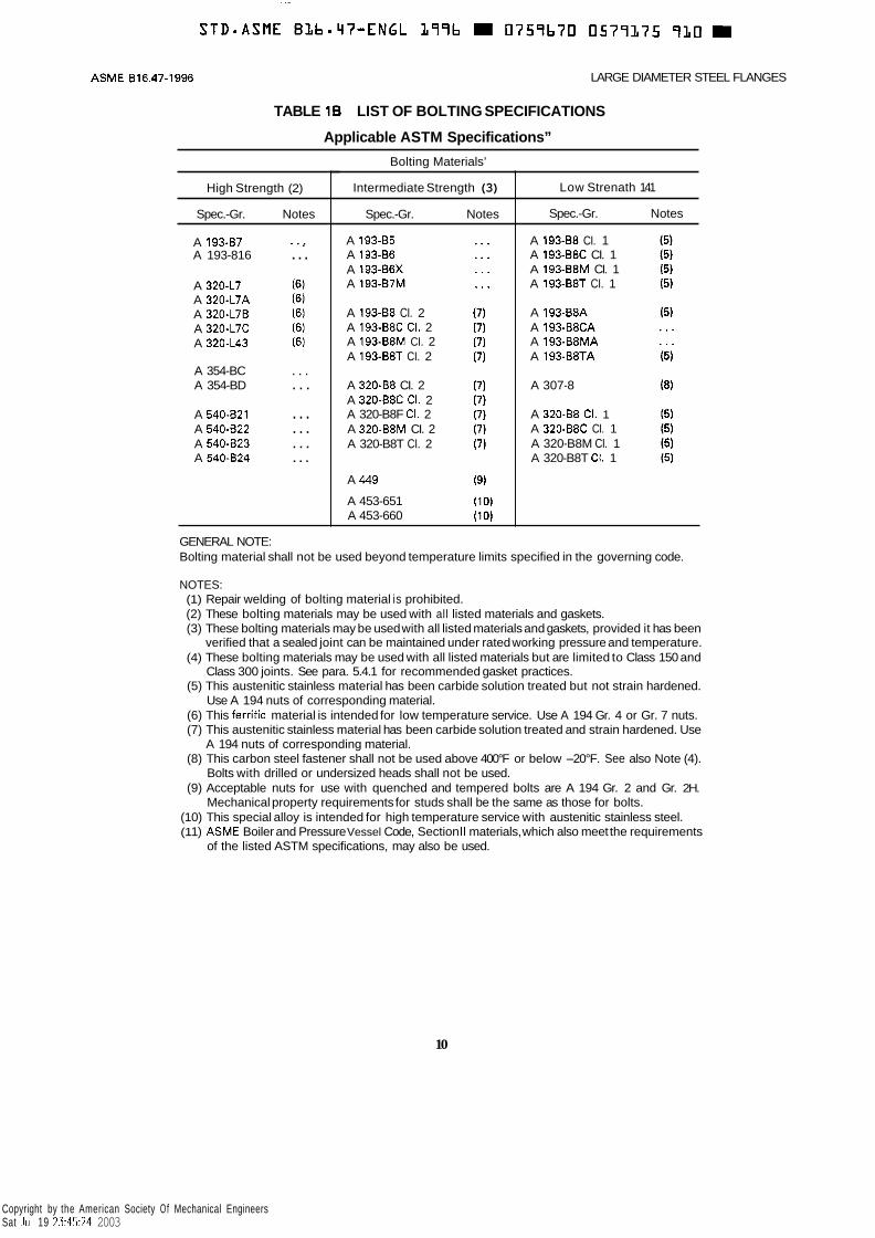
TABLE 1B LIST OF BOLTING SPECIFICATIONS
Applicable ASTM Specifications”
High Strength (2)
Spec.-Gr. Notes
A 193-87 * -, A 193-816 ...
A 320-L7 (6) A 320-L7A (6) A 320-L7B (6) A 320-L7C (6) A 320-L43 (6)
A 354-BC . . . A 354-BD . . .
A 540-B21 . . . A 540-B22 . . . A 540-823 . . . A 540-824 ...
Bolting Materials’
Intermediate Strength (3)
Spec.-Gr. Notes
A 193-85 A 193-86 A 193-B6X A 193-B7M
A 193-B8 CI. 2 A 193-B8C CI. 2 A 193-B8M CI. 2 A 193-B8T CI. 2
A 320-88 CI. 2 A 320-B8C CI. 2 A 320-B8F CI. 2 A 320-B8M CI. 2 A 320-B8T CI. 2
A 449
A 453-651 A 453-660
Low Strenath 141
Spec.-Gr. Notes
A 193-B8 CI. 1 A 193-B8C CI. 1 A 193-B8M CI. 1 A 193-B8T CI. 1
A 193-B8A A 193-B8CA A 193-B8MA A 193-B8TA
A 307-8
A 320-88 CI. 1 A 320-881: CI. 1 A 320-B8M CI. 1 A 320-B8T CI. 1
GENERAL NOTE: Bolting material shall not be used beyond temperature limits specified in the governing code.
NOTES: (1) Repair welding of bolting material is prohibited. (2) These bolting materials may be used with all listed materials and gaskets. (3) These bolting materials may be used with all listed materials and gaskets, provided it has been
verified that a sealed joint can be maintained under rated working pressure and temperature. (4) These bolting materials may be used with all listed materials but are limited to Class 150 and
Class 300 joints. See para. 5.4.1 for recommended gasket practices. (5) This austenitic stainless material has been carbide solution treated but not strain hardened.
Use A 194 nuts of corresponding material. (6) This ferritic material is intended for low temperature service. Use A 194 Gr. 4 or Gr. 7 nuts. (7) This austenitic stainless material has been carbide solution treated and strain hardened. Use
(8) This carbon steel fastener shall not be used above 400°F or below -20°F. See also Note (4).
(9) Acceptable nuts for use with quenched and tempered bolts are A 194 Gr. 2 and Gr. 2H.
A 194 nuts of corresponding material.
Bolts with drilled or undersized heads shall not be used.
Mechanical property requirements for studs shall be the same as those for bolts. (10) This special alloy is intended for high temperature service with austenitic stainless steel. (1 1) ASME Boiler and Pressure Vessel Code, Section I1 materials, which also meet the requirements
of the listed ASTM specifications, may also be used.
10
Copyright by the American Society Of Mechanical Engineers Sat Jul 19 23:45:24 2003

LARGE DIAMETER STEEL FLANGES ASME B16.47-1996
TABLES 2 PRESSURE-TEMPERATURE RATINGS FOR GROUPS 1.1 THROUGH 2.8 MATERIALS
TABLE 2-1.1 RATINGS FOR GROUP 1.1 MATERIALS
Designation Forgings I Castings Plates Nominal
C-Si 1 A 105 (1) I A 216 Gr. WCB ( 1 ) 1 A 515 Gr. 70 (1)
C-Mn-Si 1 A 350 Gr. LF2 (1) 1 A 516 Gr. 70 (1)(21 A 537 CI. 1 (3)
~ ~~
NOTES: (1) Upon prolonged exposure to temperatures above 800°F. the carbide phase of steel may be
converted to graphite. Permissible, but not recommended for prolonged use above 800°F. (2) Not to be used over 850°F. (3) Not to be used over 700°F.
Class Temp., "F ~
-20 to 100 200 300 400 500
600 650 700 750 800
850 900 950
1000
WORKING PRESSURES BY CLASSES, psig
75
140 130 115 100 85
70 60
. . .
. . . I . .
65 50 35 20
150
285 260 230 200 170
140 125 110 95 80
270 170 105 50
300
740 675 655 635 600
550 535 535 505 41 0
355 230 140 70
1350 875 1315
1270
900
2220 2025 1970 1900 1795
1640 1610 1600 1510 1235
805 515 310 155
1 1
Copyright by the American Society Of Mechanical Engineers Sat Jul 19 23:45:25 2003

ASM E 6 1 6.47- 1 996 LARGE DIAMETER STEEL FLANGES
TABLE 2-1.2 RATINGS FOR GROUP 1.2 MATERIALS
Nominal Designation
C-Mn-Si
2'/*Ni
3'/*Ni
Forgings Castings Plates
A 216 Gr. WCC (1) A 352 Gr. LCC (2)
A 352 Gr. LC2
A 352 Gr. LC3
A 203 Gr. B (1)
A 203 Gr. E (1) A 350 Gr. LF3
Class TemD.. "F
-20 to 100 200 300 400 500
600 650 700 750 800
850 900 950
1000
WORKING PRESSURES BY CLASSES, psig
75
145 130 115 100 80
70 60
. . .
. . .
. . .
. . .
. . .
. . .
. . .
150
290 260 230 200 170
140 125 110 95 80
65 50 35 20
300
750 750 730 705 665
605 590 570 505 410
270 170 105 50
12
. -
400
1000 1000 970 940 885
805 785 755 670 550
355 230 140 70
600
1500 1500 1455 1410 1330
1210 1175 1135 1010 825
535 345 205 105
900
2250 2250 2185 2115 1995
1815 1765 1705 1510 1235
805 51 5 310 155
Copyright by the American Society Of Mechanical Engineers Sat Jul 19 23:45:26 2003

S T D - A S M E BZbm'47-ENGL L77b 0757b70 0577378 b2T M
Nominal Designation
C-Si
C-Mn-Si
25iNi
3'4Ni
LARGE DIAMETER STEEL FLANGES ASME 81 6.47-1 996
TABLE 2-1.3 RATINGS FOR GROUP 1.3 MATERIALS
Forgings Castings Plates
A 352 Gr. LCB (3) A 515 Gr. 65 (1)
A 516 Gr. 65 (1)(2)
A 203 Gr. A (1)
A 203 Gr. 0 (1)
925 875 850 825 775
710 695 690 630 520
355 230 140 70
Class Temp., "F
-20 to 100 200 300 400 500
600 650 700 750 800
850 900 950
1000
1390 1315 1275 1235 1165
1065 1045 1035 945 780
535 345 205 105
WORKING PRESSURES BY CLASSES, psig
75
130 125 115 100 85
70 60
. . .
...
...
. . .
. . .
. . .
. . .
150
265 250 230 200 170
140 125 110 95 80
65 50 35 20
300
695 655 640 620 585
535 525 520 475 390
270 170 105 50
400 1 600 900
2085 1970 1915 1850 1745
1600 1570 1555 1420 1175
805 515 310 155
13
Copyright by the American Society Of Mechanical Engineers Sat Jul 19 23:45:27 2003
S T D - A S M E BLb.47-ENGL L77b m 0759b70 0577277 5bb m
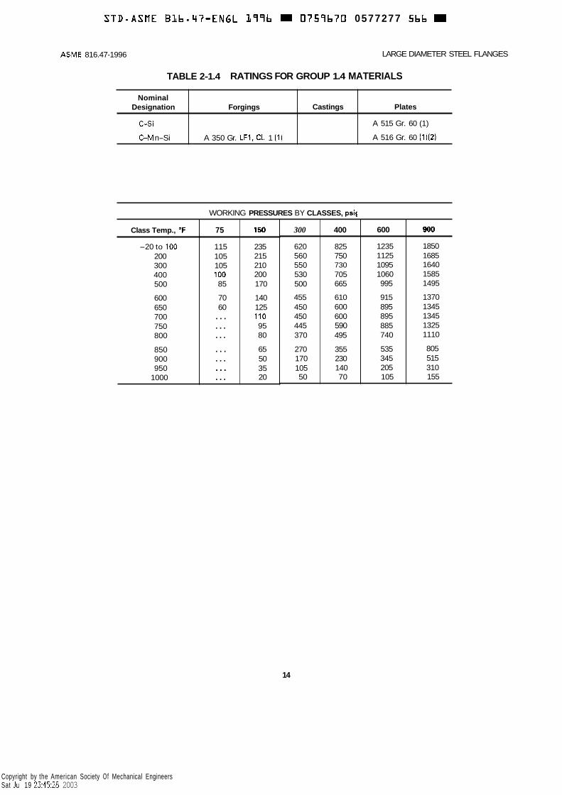
Nominal Designation Forgings
C-Si
C M n-Si A 350 Gr. LF1, CI. 1 (1)
ASME 816.47-1996 LARGE DIAMETER STEEL FLANGES
Castings Plates
A 515 Gr. 60 (1)
A 516 Gr. 60 (1)(2)
TABLE 2-1.4 RATINGS FOR GROUP 1.4 MATERIALS
75
115 105 105 100 85
70 60 ... ... ... . . . ... ... ...
150
235 215 210 200 170
140 125 110 95 80
65 50 35 20
~~
Class Temp., O F
-20 to 100 200 300 400 500
600 650 700 750 800
850 900 950
1000
WORKING PRESSURES BY CLASSES, psi(
300
620 560 550 530 500
455 450 450 445 370
270 170 105 50
400
825 750 730 705 665
610 600 600 590 495
355 230 140 70
600
1235 1125 1095 1060 995
915 895 895 885 740
535 345 205 105
900
1850 1685 1640 1585 1495
1370 1345 1345 1325 1110
805 515 310 155
14
Copyright by the American Society Of Mechanical Engineers Sat Jul 19 23:45:28 2003
S T D n A S f l E BLbmq7-ENGL It996 0759b70 057’7380 288 D
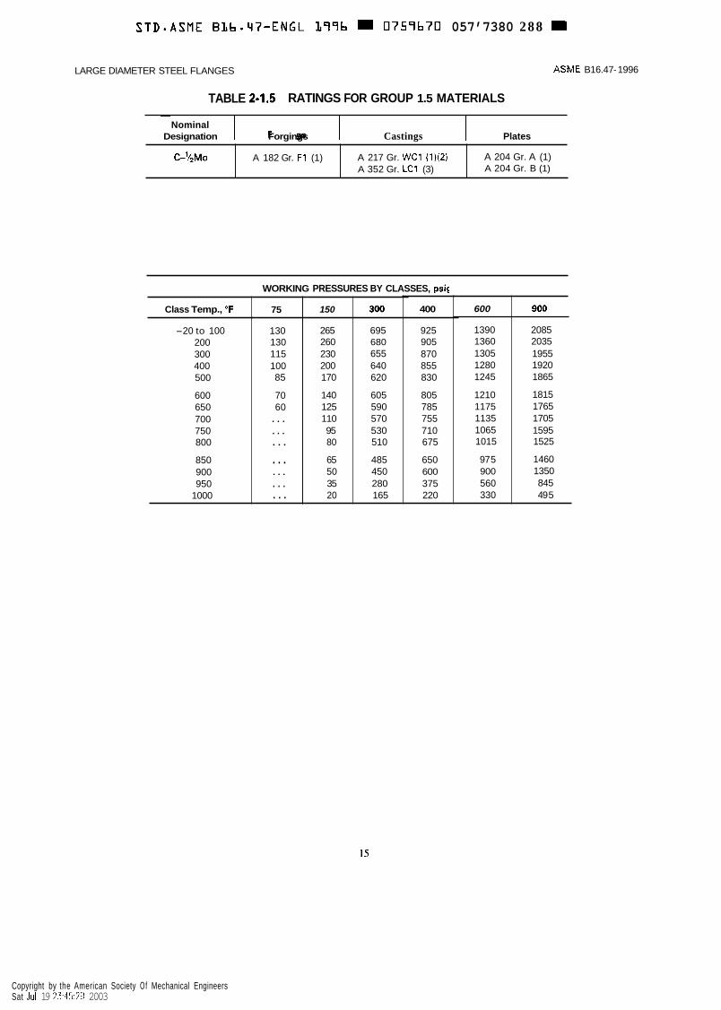
C-’/~MO
LARGE DIAMETER STEEL FLANGES ASME B16.47- 1996
TABLE 2-1.5 RATINGS FOR GROUP 1.5 MATERIALS
A 182 Gr. F1 (1) A 217 Gr. WC1 (1)(2) A 352 Gr. LC1 (3)
A 204 Gr. A (1) A 204 Gr. B (1)
~ 1 - Forgings - 1 - Castings Plates Nominal
Designation
600
1390 1360 1305 1280 1245
1210 1175 1135 1065 1015
97 5 900 560 330
900
2085 2035 1955 1920 1865
1815 1765 1705 1595 1525
1460 1350 845 49 5
Class Temp., “F
-20 to 100 200 300 400 500
600 650 700 750 800
850 900 950
1000
WORKING PRESSURES BY CLASSES, psir
75
130 130 115 100 85
70 60
. . .
. . .
. . .
. . .
. . .
. . .
. . .
150
265 260 230 200 170
140 125 110 95 80
65 50 35 20
300
695 680 655 640 620
605 590 570 530 510
485 450 280 165
- . - 400
925 905 870 855 830
805 785 755 710 675
650 600 375 220
15
Copyright by the American Society Of Mechanical Engineers Sat Jul 19 23:45:29 2003

STD-ASME BLb.47-ENGL 199b m 0759670 05771AL 1/11
Nominal Designation
C-’/2Mo
‘/2Cr-l/2Mo
Ni-1/2Cr-’/ZMo
3/4Ni-3/4Cr-1Mo
ASME 816.47-1996 LARGE DIAMETER STEEL FLANGES
Forgings Castings Plates
A 204 Gr. C (2)
A 182 Gr. F2 (3)
A 217 Gr. WC4 (1)(3)
A 217 Gr. WC5 (1)
. -
400
1000 1000 965 925 885
805 785 755 710 675 650 600 420 270 210
WORKING PRESSURES BY CLASSES. Dsis
600
1500 1500 1445 1385 1330
1210 1175 1135 1065 1015 975 900 630 405 315
Class Temp., T
-20 to 100 200 300 400 500
600 650 700 750 800 850 900 950
1000 1050
150 75
145 130 115 100 85
70 60
. . .
. . .
. . .
. . .
. . .
. . .
. . .
. . .
290 260 230 200 170
140 125 110 95 80 65 50 35 20 ...
300
750 750 720 695 665
605 590 570 530 510 485 450 31 5 200 160
900
2250 2250 2165 2080 1995
1815 1765 1705 1595 1525 1460 1350 945 605 475
16
Copyright by the American Society Of Mechanical Engineers Sat Jul 19 23:45:30 2003

STD-ASME BLb.47-ENGL 377b m 0759b70 0579382 050
Nominal Designation
lCr-’/*Mo
1 1/4Cr-1/2Mo
11/$r-1/2Mo
LARGE DIAMETER STEEL FLANGES ASME B 16.47-1 996
Forgings Castings Plates
A 182 Gr. F12 CI. 2 (1)(2)
A 217 Gr. WC6 (1)(3)
A 182 Gr. F11 CI. 2 (1)(2) A 387 Gr. 11 CI. 2 (2)
WORKING PRESSURES BY CLASSES, Dsia
Class Temn., O F
-20 to 100 200 300 400 500
600 650 700 750 800
850 900 950
1000 1050
1100 1150 1200
75
145 130 115 100 85
70 60
. ..
. . .
. . . * . . . . . . . . . . . . . . . . . ... . . .
150
290 260 230 200 170
140 125 110 95 80
65 50 35 20
...
...
...
...
300
750 750 720 695 665
605 590 570 530 51 0
485 450 320 215 145
95 60 40
- . - 400
1000 1000 965 925 885
805 785 755 710 675
650 600 425 290 190
130 80 50
600
1500 1500 1445 1385 1330
1210 1175 1135 1065 1015
975 900 640 430 290
190 125 75
900
2250 2250 2165 2080 1995
1815 1765 1705 1595 1525
1460 1350 955 650 430
290 185 115
17
Copyright by the American Society Of Mechanical Engineers Sat Jul 19 23:45:31 2003
STD*ASME BLb*'47-ENGL L77b 0757b70 0577383 T77
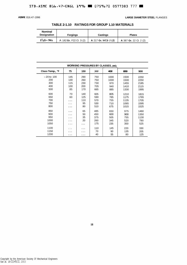
Nominal Designation
2v4Cr-lMo
ASME 816.47-1996 LARGE DIAMETER STEEL FLANGES
Forgings Castings Plates
A 217 Gr. WC9 (1)(3) A 182 Gr. F22 CI. 3 (2) A 387 Gr. 22 CI. 2 (2)
TABLE 2-1.10 RATINGS FOR GROUP 1.10 MATERIALS
Class Temp., "F
-20 to 100 200 300 400 500
600 650 700 750 800
850 900 950
1000 1050
1100 1150 1200
WORKING PRESSURES BY CLASSES, psir
75
145 130 115 100 85
70 60
...
...
. . .
...
...
. . .
. . .
. . .
. . .
. . .
. . .
150
290 260 230 200 170
140 125 110 95 80
65 50 35 20
...
...
. . .
. . .
300
750 750 730 705 665
605 590 570 530 510
485 450 375 260 175
110 70 40
18
. -
400
1000 1000 970 940 885
805 785 755 710 675
650 600 505 345 235
145 90 55
600
1500 1500 1455 1410 1330
1210 1175 1135 1065 1015
975 900 755 520 350
220 135 80
900
2250 2250 2185 2115 1995
1815 1765 1705 1595 1525
1460 1350 1130 780 525
330 205 125
Copyright by the American Society Of Mechanical Engineers Sat Jul 19 23:45:32 2003

~
S T D - A S M E BLb-47-ENGL 377b 0757b70 0577384 723
Nominal Designation
5Cr-Y2Mo
LARGE DIAMETER STEEL FLANGES ASME B16.47- 1996
Forgings Castings Plates
A 182 Gr. F5 A 182 Gr. F5a A 217 Gr. C5 (1)
Class Temp., "F
-20 to 100 200 300 400 500
600 650 700 750 800
850 900 950
1000 1050
1100 1150 1200
WORKING PRESSURES BY CLASSES, psig
75 150 300 400 600 900
145 290 750 1000 1500 2250 130 260 745 995 1490 2235 115 230 715 955 1430 2150 100 200 705 940 1410 2115 85 170 665 885 1330 1995
70 140 605 805 1210 1815 60 125 590 785 1175 1765 ... 110 570 755 1135 1705 . .. 95 530 705 1055 1585 . .. 80 51 0 675 1015 1525
. . . 65 485 645 965 1450 * . . 50 370 495 740 1110 . . . 35 275 365 550 825 . . . 20 200 265 400 595 . . . . . . 145 190 290 430
. . . ... 100 135 200 300
. . . ... 60 80 125 185
. .. ... 35 45 70 105
19
Copyright by the American Society Of Mechanical Engineers Sat Jul 19 23:45:33 2003

STD-ASME BLb*q7-ENGL
Nominal Designation
L99b 0757b70 0577185 8bT
Forgings Castings Plates
ASME 816.47-1996 LARGE DIAMETER STEEL FLANGES
9Cr-1 Mo 1 ~~~ ~
A 182 Gr. F9 A 217 Gr. C12 (1)
300
750 750 730 705 665
605 590 570 530 510
485 450 375 255 170
115 75 50
WORKING PRESSURES BY CLASSES, psig
400
1000 1000 970 940 885
805 785 755 710 675
650 600 505 340 230
150 100 70
Class Temp., OF
-20 to 100 200 300 400 500
600 650 700 750 800
850 900 950
1000 1050
1100 1150 1200
75
145 130 115 100 85
70 60
. . .
. . .
. . .
. . .
. . .
. . .
. . .
. . .
. . .
. . .
. . .
150
290 260 230 200 170
140 125 110 95 80
65 50 35 20
. . .
. . .
. ..
. . .
600
1500 1500 1455 1410 1330
1210 1175 1135 1065 1015
975 900 755 505 345
225 150 105
900
2250 2250 2185 2115 1995
1815 1765 1705 1595 1525
1460 1350 1130 760 515
340 225 155
20
Copyright by the American Society Of Mechanical Engineers Sat Jul 19 23:45:34 2003
LARGE DIAMETER STEEL FLANGES ASME 01 6.47-1 996
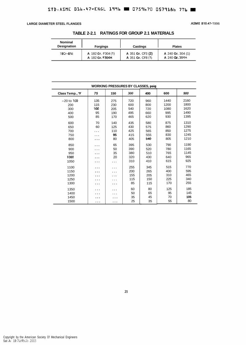
TABLE 2-2.1 RATINGS FOR GROUP 2.1 MATERIALS
18Cr-8Ni
I Forgings Castings Plates Nominal
Designation
A 182 Gr. F304 (1) A 182 Gr. F304H
A 351 Gr. CF3 (2) A 351 Gr. CF8 (1)
A 240 Gr. 304 (1) A 240 Gr. 304H
WORKING PRESSURES BY CLASSES, psig
Class Temp., O F ~
-20 to 100 200 300 400 500
600 650 700 7 50 800
850 900 950
1000 1050
1100 1150 1200 1250 1300
1350 1400 1450 1500
75
135 115 100 95 85
70 60
. . .
. . .
. . .
. . .
. . .
. ..
...
. . .
...
...
...
. . .
. . .
. . .
. . .
. . .
. . .
150
275 230 205 190 170
140 125 110 95 80
65 50 35 20
. . .
. . .
. . . . . a
. . .
. . .
. . .
. . .
. . .
. . .
300
720 600 540 495 465
435 430 425 41 5 405
395 390 380 320 310
255 200 155 115 85
60 50 35 25
400
960 800 720 660 620
580 575 565 555 540
530 520 510 430 410
345 265 205 150 115
80 65 45 35
600
1440 1200 1080 995 930
875 860 850 830 805
790 780 765 640 615
515 400 310 225 170
125 95 70 55
900
2160 1800 1620 1490 1395
1310 1290 1275 1245 1210
1190 1165 1145 965 925
770 595 465 340 255
185 145 105 80
21
Copyright by the American Society Of Mechanical Engineers Sat Jul 19 23:45:35 2003

STD-ASME B L b m q 7 - E N G L L77b M 0757b70 0577387 b32
Nominal Designation
16Cr-12Ni-2Mo
18Cr-13Ni-3Mo
19Cr-1 ONi-3Mo
ASME 816.47-1996 LARGE DIAMETER STEEL FLANGES
TABLE 2-2.2 RATINGS FOR GROUP 2.2 MATERIALS
Forgings Castings Plates
A 351 Gr.CF3M (2) A 351 Gr. CF8M (1)
A 182 Gr. F316 (1) A 182 Gr. F316H
A 240 Gr. 316 (1) A 240 Gr. 316H
A 240 Gr. 317 (1)
A 351 Gr. CG8M (3)
Class Temp., "F
-20 to 100 200 300 400 500
600 650 700 750 800
850 900 950
1000 1050
1100 1150 1200 1250 1300
1350 1400 1450 1500
WORKING PRESSURES BY CLASSES. osi
75
135 115 105 95 a5
70 60 ... ... ... ... ... ... ... ... ... . . . . . . . . . . . . . . . . . . . . . . . .
150
275 235 215 195 170
140 125 110 95 80
65 50 35 20
. . . * . . . . . . . . . . . . . . . . . . .. ... ...
300
720 620 560 515 480
450 445 430 425 420
420 415
350 345
305 235
145 115
95 75 60 40
385
1 a5
. . 400
960 825 745 685 635
600 590
570 565
555 555 51 5 465 460
405 315 245 195 155
130 100
55
580
ao
600
1440 1240 1120 1025 955
900 890
855 a70
a45
835 830 775 700 685
610 475 370 295 235
190 150 115 85
900
2160 1860 1680 1540 1435
1355 1330 1305 1280 1265
1255 1245 1160 1050 1030
915 710 555 440 350
290 225 175 125
22
Copyright by the American Society Of Mechanical Engineers Sat Jul 19 23:45:36 2003

STD-ASME BLbmq7-ENGL L77b m 0759b70 0577188 577 =
18Cr-8Ni
16Cr-12Ni-2Mo
LARGE DIAMETER STEEL FLANGES ASME B 16.47-1 996
TABLE 2-2.3 RATINGS FOR GROUP 2.3 MATERIALS
A 182 Gr. F304L (1)
A 182 Gr. F316L
A 240 Gr. 304L (1)
A 240 Gr. 316L
Nominal I
Class Temp., "F 75 150 300 400 600
-20 to 100 115 230 600 800 1200 200 95 195 505 675 1015 300 85 175 455 605 910 400 80 160 41 5 550 825 500 70 145 380 510 765
600 70 140 360 480 720 650 60 125 350 470 700 700 . . . 110 345 460 685 750 . . . 95 335 450 670 800 . . . 80 330 440 660
850 . . . 65 320 430 645
I --I
900
1800 1520 1360 1240 1145
1080 1050 1030 1010 985
965
Designation 1 Forgings I Castings I Plates
NOTE: (1) Not to be used over 800°F.
23
Copyright by the American Society Of Mechanical Engineers Sat Jul 19 23:45:37 2003
STD-ASME BLb.47-ENGL L77b 0757b70 0577387 405
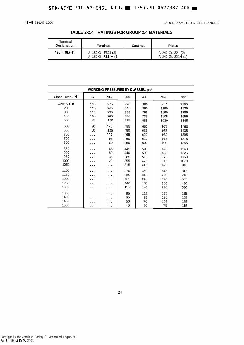
Nominal Designation
18Cr-1ONi-Ti
ASME 816.47-1996 LARGE DIAMETER STEEL FLANGES
TABLE 2-2.4 RATINGS FOR GROUP 2.4 MATERIALS
Forgings Castings Plates
A 182 Gr. F321 (2) A 182 Gr. F321H (1)
A 240 Gr. 321 (2) A 240 Gr. 321H (1)
75
135 120 115 100 85
70 60
. . .
. . .
. . .
. . .
. . .
. . .
. . .
. . .
. . .
. . .
. ..
...
...
. . .
...
...
Class Temp., “F
-20 to 100 200 300 400 500
600 650 700 750 800
850 900 950
1000 1050
1100 1150 1200 1250 1300
1350 1400 1450 1500
150
275 245 230 200 170
140 125 110 95 80
65 50 35 20
. ..
...
...
. . .
. . .
. . .
. . .
. . .
. . .
. . .
WORKING PRESSURES BY CLI
300
720 645 595 550 515
485 480 465 460 450
‘445 440 385 355 31 5
270 235 185 140 110
85 65 50 40
iSES, psi!
400
960 860 795 735 685
650 635 620 610 600
595 590 515 475 415
360 315 245 185 145
115 85 70 50
600
1440 1290 1190 1105 1030
975 955 930 915 900
895 885 775 715 625
545 475 370 280 220
170 130 105 75
900
2160 1935 1785 1655 1545
1460 1435 1395 1375 1355
1340 1325 1160 1070 940
81 5 710 555 420 330
255 195 155 115
24
Copyright by the American Society Of Mechanical Engineers Sat Jul 19 23:45:38 2003
STDOASME BLb.47-ENGL L97b M 0757b70 0577370 127 W
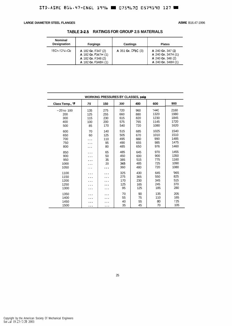
Nominal Designation
18Cr-lONi-Cb
LARGE DIAMETER STEEL FLANGES ASME B16.47-1996
TABLE 2-2.5 RATINGS FOR GROUP 2.5 MATERIALS
Forgings Castings Plates
A 182 Gr. F347 (2) A 182 Gr. F347H (1) A 182 Gr. F348 (2) A 182 Gr. F348H (1)
A 351 Gr. CF8C (3) A 240 Gr. 347 (2) A 240 Gr. 347H (1) A 240 Gr. 348 (2) A 240 Gr. 348H (1)
. -
400
960 880 820 765 720
685 670 660 655 650
645 600 51 5 485 480
430 365 230 165 125
90 75 55 45
Class Temp., O F 600
1440 1320 1230 1145 1080
1025 1010 990 985 976
970 900 775 725 720
645 550 345 245 185
135 110 80 70
-20 to 100 200 300 400 500
600 650 700 750 800
850 900 950
1000 1050
1100 1150 1200 1250 1300
1350 1400 1450 1500
WORKING PRESSURES BY CLASSES, psig
75
135 125 115 100 85
70 60 . . . . . . . . . . . . . . . . . . . . . * . . . . . . . . . .. . . . ... ... ... ... ...
150
275 255 230 200 170
140 125 110 95 80
65 50 35 20 ... ... ... ... ... ... ... . . . . . . . . .
300
720 660 615 575 540
515 505 495 490 485
485 450 385 365 360
325 275 170 125 95
70 55 40 35
~
900
2160 1980 1845 1720 1620
1540 1510 1485 1475 1460
1455 1350 1160 1090 1080
'965 825 51 5 370 280
205 165 7 25 105
25
Copyright by the American Society Of Mechanical Engineers Sat Jul 19 23:45:39 2003

STD-ASME BLb.47-ENGL L99b 0759b70 0577191 Oh3
Nominal Designation
25Cr-12Ni
23Cr-12Ni
ASME 816.47-1996 LARGE DIAMETER STEEL FLANGES
TABLE 2-2.6 RATINGS FOR GROUP 2.6 MATERIALS
Forgings Castings Plates
A 351 Gr. CH8 (1) A 351 Gr. CHZO (1)(4)
A 240 Gr. 3095 (1)(2)(3) A 240 Gr. 309H
300
NOTES: (1) At temperatures over IOOO"F, use only when the carbon content is 0.04% or higher. (2) For temperatures above lOOO'F, use only if the material is heat treated by heating it to a
temperature of at least 1900°F and quenching in water or rapidly cooling by other means. (3) This material should be used for service temperatures 105OOF and above only when assurance
is provided that grain size is not finer than ASTM 6. (4) For service temperatures above 850°F, it is recommended that killed steel containing not less
than 0.10% residual silicon be used.
400 600 Class Temp., O F
670 605 570 535 505
480 465 455 445 435
425 41 5 385 335 290
225 170 130 100 80
60 45 30 25
-20 to 100 200 300 400 500
600 650 700 750 800
850 900 950
1000 1050
1100 1150 1200 1250 1300
1350 1400 1450 1500
895 805 760 710 670
635 620 610 595 580
565 555 515 450 390
300 230 175 135 105
80 60 40 30
WORKING PRESSURES BY CLASSES, Dsia
75
130 115 110 100 85
70 60
. . .
. . .
. . .
. . .
. . .
. . .
. . .
. . .
. . .
. . .
...
...
...
. . .
. ..
. . .
150
260 230 220 200 170
140 125 110 95 80
65 50 35 20
...
. . .
. . .
. . .
. . .
. . .
. . .
. . .
. , .
. . .
1345 1210 1140 1065 1010
955 930 910 895 870
850 830 775 670 585
445 345 260 200 160
115 90 60 50
900
2015 1815 1705 1600 1510
1435 1395 1370 1340 1305
1275 1245 1160 1010 875
670 515 390 300 235
175 135 95 70
26
Copyright by the American Society Of Mechanical Engineers Sat Jul 19 23:45:40 2003

STD-ASME B L b - q T - E N G L L77b D 0757b70 D577172 T T T D
Forgings Castings
A 182 Gr. F310 (1)(3) A 351 Gr. CK20 (1)
LARGE DIAMETER STEEL FLANGES ASME 816.47-1996
Plates
A 240 Gr. 310s (1)(2)(3) A 240 Gr. 310H
TABLE 2-2.7 RATINGS FOR GROUP 2.7 MATERIALS
Nominal Designation
25Cr-20Ni
NOTES: (1) At temperatures over 1000°F. use only when the carbon content is 0.04% or higher. (2) For temperatures above 1000°F. use only if the material is heat treated by heating it to a
temperature of at least 1900°F and quenching in water or rapidly cooling by other means. (3) Service temperatures of 1050°F and above should be used only when assurance is provided
that grain size is not finer than ASTM 6.
Class Temp., "F
-20 to 100 200 300 400 500
600 650 700 750 800
850 900 950
1000 1050
1100 1150 1200 1250 1300
1350 1400 1450 1500
WORKING PRESSU
75
130 115 110 100 85
70 60
. . .
. . .
. . .
. . .
. ..
. . .
. . .
. . .
. . .
. . .
. . .
. . .
. . .
. . .
. . .
. . .
. . .
150
260 235 220 200 170
140 125 110 95 80
65 50 35 20 ... ... ... ... ... ... ... . . . . . . . . .
iS BY CLASSES, psi!
300
670 605 570 535 505
480 470 455 450 435
425 420 385 345 335
260 190 135 105 75
60 45 35 25
400
895 810 760 715 675
640 625 610 600 580
575 555 515 460 450
345 250 185 135 100
80 60 45 35
600
1345 1215 1140 1070 1015
960 935 910 900 875
855 835 775 685 670
520 375 275 205 150
115 90 65 50
900
201 5 1820 1705 1605 1520
1440 1405 1370 1345 1310
1280 1255 1160 1030 1010
780 565 410 310 225
175 135 100 75
27
Copyright by the American Society Of Mechanical Engineers Sat Jul 19 23:45:41 2003

STD.ASME BLb.47-ENGL L77b 0 7 5 7 b 7 0 0577373 73b m
Nominal Designation
20Cr-18Ni-6Mo
22Cr-5Ni-3Mo-N
250-7Ni4Mo-N
ASME 816.47-1996 LARGE DIAMETER STEEL FLANGES
Forgings Castings Plates
A 351 Gr. CK3MCuN A 182 Gr. F44
A 182 Gr. F51 (1)
A 182 Gr. F53 (1)
A 240 Gr. S31254
A240 Gr. 531803 (1)
A 240 Gr. S32750 (1)
75 150 300 400 600
145 290 750 1000 1500 130 260 720 960 1440 115 230 665 885 1330 100 200 615 a20 1230 85 170 575 770 1150
70 140 555 740 1115 60 125 550 735 1100 ... 110 540 725 I 085 ... 95 530 710 1065
NOTE: (1) This steel may become brittle after service at moderately elevated temperatures. Not to be
used over 600°F.
900
2250 2160 1995 1845 1730
1670 1650 '1625 1595
Class TernD., 'F
-20 to 100 200 300 400 500
600 650 700 750
28
Copyright by the American Society Of Mechanical Engineers Sat Jul 19 23:45:42 2003

~
S T D - A S M E BLb.47-ENGL 399b m 0759b70 0579394 872
LARGE DIAMETER STEEL FLANGES ASME B16.47-1996
23 deg. p- Kmin. 4
TABLE 3 DIMENSIONS OF RING-JOINT > Nominal PiDe Size
300 I 400
- 600
26 28 30 32 34 36
-
...
. , .
. , .
. . .
. . .
. . . -
Groove Number
R97
R100 R l O l R102 R103
34 R104 36 R105
~ ~
Pitch Diam.
P
29.500 31.500 33.750 36.000 38.000 40.250 29.500 31.500 33.750 36.000 38.000 40.250
Groove Dimensions -
Depth
E
0.500 0.500 0.500 0.562 0.562 0.562 0.688 0.688 0.688 0.688 0.81 2 0.81 2 -
-
Width
F - 0.781 0.781 0.781 0.906 0.906 0.906 1.188 1.312 1.312 1.312 1.438 1.438 -
Radius at
Bottom
R
0.06 0.06 0.06 0.06 0.06 0.06 0.09 0.09 0.09 0.09 0.09 0.09
Diameter of
Raised Portion
K
31.88 33.88 36.12 38.75 40.75 43.00 32.75 35.00 37.25 39.50 42.00 44.25
Tolerances
E [depth)
F (width) P (pitch diameter) R (radius at bottom) 23 deg. (angle)
+0.016 -0 k0.008 +0.005 Max. k’/2 deg.
GENERAL NOTES: (a) Dimensions are in inches. (b) Ring-joint gaskets are not contemplated for NPS 38 and larger flanges.
NOTES: (1) Height of raised portion is equal to the depth of groove dimension €, but is not subjected to
the tolerances for E. Full face contour may be used. (2) For facing requirements for flanges, see para. 6.1.1. (3) See para. 4.1.7 for marking requirements.
29
Copyright by the American Society Of Mechanical Engineers Sat Jul 19 23:45:43 2003
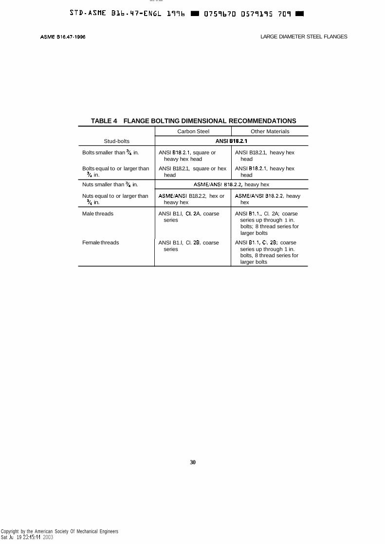
ASME 818.47-1996 LARGE DIAMETER STEEL FLANGES
Stud-bolts
Bolts smaller than 3/4 in.
Bolts equal to or larger than % in.
TABLE 4 FLANGE BOLTING DIMENSIONAL RECOMMENDATIONS Carbon Steel Other Materials
ANSI 818.2.1
ANSI 818.2.1, square or
ANSI B18.2.1, square or hex
ANSI B18.2.1, heavy hex
ANSI 818.2.1, heavy hex
heavy hex head head
head head
Nuts smaller than y4 in.
Nuts equal to or larger than Y4 in.
ASMUANSI 618.2.2, heavy hex
ASMWANSI B18.2.2, hex or ASME/ANSI 818.2.2, heavy heavy hex hex
Male threads ANSI B1.l, CI. 2A. coarse series
ANSI B1.1., CI. 2A; coarse series up through 1 in. bolts; 8 thread series for larger bolts
Female threads
30
ANSI B1.l, CI. 28. coarse ANSI 81.1. CI. 28; coarse series up through 1 in. bolts, 8 thread series for larger bolts
series
Copyright by the American Society Of Mechanical Engineers Sat Jul 19 23:45:44 2003

LARGE DIAMETER STEEL FLANGES ASME 016.47-1996
WELDING ENDS (Welding Neck Flanges, No Backing Rings)
r- Slope 1:3 (max.)
37- 112 deg. fr 2-112 deg.
A 8
i i
37-
X
r Slope 1:3 ( m v I I
10 deg. f 1 deg. 0.12 min. radius I 1
\
I t I V
.-..,
4
0.06'+_ 0.03 l l A B
i f X
f FIG. 1 BEVEL FOR WALL THICKNESSES r FROM FIG. 2 BEVEL FOR WALL THICKNESSES t
0.19 in. TO 0.88 in., INCLUSIVE'-3 GREATER THAN 0.88 in.'-3
A = nominal outside diameter of pipe, in. 6 = nominal inside diameter of pipe, in. r = nominal wall thickness of pipe, in.
NOTES: (1 I See paras. 6.4 and 7.4 for details and tolerances. (2) See Figs. 3 and 4 for additional details of welding ends. (31 When the thickness of the hub at the bevel is greater than that of the pipe to which the flange is joined, and the additional thickness
is provided on the outside diameter, a taper weld having a slope not exceeding 1 to 3 may be employed or* alternatively, the greater outside diameter may be tapered, a t the same maximum slope or less, from a point on the welding bevel equal to the 0.0. of the mating pipe. Similarly, when the greater thickness is provided on the inside of the flange, it shall be taper bored from the welding end a t a slope not exceeding 1 to 3.
When flanges covered by this Standard are intended for services with light wall and higher strength pipe, the thickness of the hub at the bevel may be greater than that of the pipe to which the flange is pined. Under these conditions a single taper hub may be pro- vided and the outside diameter of the hub at the base (dimension X ) may also be modified.
The additional thickness may be provided on either inside or outside or partially on each side, but the total additional thickness shall not exceed one-half times the nominal wall thickness of intended mating pipe. See Figs. 5,6, and 7.
31
Copyright by the American Society Of Mechanical Engineers Sat Jul 19 23:45:45 2003

ASME 816.47-1996 LARGE DIAMETER STEEL FLANGES
WELDING ENDS (Welding Neck Flanges With Backing Rings)
FIG. 3 INSIDE CONTOUR FOR USE WITH FIG. 4 INSIDE CONTOUR FOR USE WITH TAPER RECTANGULAR BACKING RING’-3 BACKING RING’-3
A = nominal outside diameter of welding end, in. B = nominal inside diameter of pipe
C = A - 0.031 - 1.75t - 0.010 in. t = nominal wall thickness of pipe, in.
= A - 2t. in.
0.031 = minus tolerance on O.D. of pipe, in. 1.75t = 87%% of nominal wall multiplied by two to convert into terms of diameter 0.010 = plus tolerance on diameter C, in. (see para. 7.4.3.)
NOTES: (1) 0.5 in. depth based on use of 0.75 in. wide backing ring. (2) See paras. 6.4 and 7.4 for details and tolerances. (3) See Figs. 1 and 2 for welding end details of welding neck flanges.
32
Copyright by the American Society Of Mechanical Engineers Sat Jul 19 23:45:46 2003

STD-ASME BL b m Y 7 - E N G L L97b M 0757b70 0577398 q L 8
LARGE DIAMETER STEEL FLANGES ASME 816.47-1996
WELDING ENDS (Welding Neck Flanges)
ADDITIONAL THICKNESS FOR WELDING TO HIGHER STRENGTH PIPE
\ 18 deg. max. (1:3)
FIG. 5 BEVEL FOR OUTSIDE THICKNESS'-3 FIG. 6 BEVEL FOR INSIDE THICKNESS'"
18 deg. max. ( 1 3 1
FIG. 7 BEVEL FOR COMBlNED
NOTES: (1) Neither f l , t2, nor their sum ( t l + t2) shall exceed 0 . 5 ~ (2) When the minimum specified yield strengths of the sections to be joined are unequal, the value of r, shall at least equal t times the
(3) Welding shall be in accordance with the applicable code. ratio of minimum specified yield strength of the pipe to yield strength of the flange.
33
Copyright by the American Society Of Mechanical Engineers Sat Jul 19 23:45:47 2003

~~
STDOASME BLb-W-ENGL L99b 0757b70 0577179 35q M
54
56
58
60
ASME B16.47-1996 LARGE DIAMETER STEEL FLANGES
66.25 4.75 4.75 8.50 55.25 54.00 59.50 62.75 44 1.88 13/4 0.50
68.75 4.88 4.88 9.00 57.38 56.00 62.00 65.00 48 1.88 13/4 0.50
71.00 5.06 5.06 9.25 59.38 58.00 64.00 67.25 48 1.88 174 0.50
73.00 5.19 5.19 9.44 61.38 60.00 66.00 69.25 52 1.88 13/4 0.50
34
Copyright by the American Society Of Mechanical Engineers Sat Jul 19 23:45:48 2003

S T D - A S M E BLbm'i7-ENGL L79b 0757b70 0577200 7Tb
48
50
52
54
56
58
60
LARGE DIAMETER STEEL FLANGES ASME 616.47-1996
57.75 5.25 5.25 8.81 49.38 48.00 51.25 54.00 32 2.00 i718 0.50
60.25 5.50 5.50 9.12 51.38 50.00 53.50 56.25 32 2.12 2 0.50
62.25 5.69 5.69 9.38 53.38 52.00 55.50 58.25 32 2.12 2 0.50
65.25 6.00 6.00 9.94 55.50 54.00 57.75 61.00 28 2.38 2'/4 0.50
67.25 6.06 6.06 10.25 57.62 56.00 59.75 63.00 28 2.38 2'/4 0.50
69.25 6.25 6.25 10.50 59.62 58.00 62.00 65.00 32 2.38 25h 0.50
71.25 6.44 6.44 10.75 61.62 60.00 64.00 67.00 32 2.38 2'/4 0.50
TABLE 6 DIMENSIONS OF CLASS 300 SERIES A FLANGES16
1 1 2 1 3 1 4 1 5 1 6 1 7 1 8 1 9 1 10 I 11 I 12 I 13
35
Copyright by the American Society Of Mechanical Engineers Sat Jul 19 23:45:49 2003

STD-ASME BLb.Li7-ENGL
56
58
60
ASME 816.47-1996
69.00 6.88 6.94 11.75 58.25 56.00 60.12 64.25 32 2.62 2'/2 0.56
71.00 7.00 7.12 12.06 60.25 58.00 62.12 66.25 32 2.62 2'12 0.56
74.25 7.31 7.44 12.56 62.38 60.00 64.38 69.00 32 2.88 z3/4 0.56
177b 0757b70 0577201 832
LARGE DIAMETER STEEL FLANGES
36
Copyright by the American Society Of Mechanical Engineers Sat Jul 19 23:45:50 2003

STD-ASME BLbmq7-ENGL 177b 0757b70 0579202
Nominal Pipe Size
777 m
Thickness of 0. D. Flange, Min? Length of Through
Flange WNF Blind Hub
0 C C Y
LARGE DIAMETER STEEL FLANGES ASME 816.47-1996
~
Hub Diam? T~~
A
TABLE 8 DIMENSIONS OF CLASS 600 SERIES A FLANGES14
1 1 2 1 3 1 4 1 5 7 1 8 1 9 1 10 I 11 I 12 I 13 ~ ~~ ~
Raised Drilling Face '
Diam. Diam. No. Of Diam. of Bolt Bolt of Bolt
R Circle Holes Hole
28
30
32
Diam. of
Hub'
42.25 4.38 5.19 9.25 31.62 28.00 31.50 38.00 28 2.12 2 0.50
44.50 4.50 5.50 9.75 33.94 30.00 33.75 40.25 28 2.12 2 0.50
47.00 4.62 5.81 10.25 36.12 32.00 36.00 42.50 28 2.38 294 0.50
i x
34
36
49.00 4.75 6.06 10.62 38.31 34.00 38.00 44.50 28 2.38 25h 0.56
51.75 4.88 6.38 11.12 40.62 36.00 40.25 47.00 28 2.62 2l/2 0.56
Diam. of
Bolt
38
40
Fillet Radius Min.
50.00 6.00 6.12 10.00 40.25 38.00 41.50 45.75 28 2.38 21/4 0.56
52.00 6.25 6.38 10.38 42.25 40.00 43.75 47.75 32 2.38 25b 0.56
I rl
44
46
48
26 1 40.00 1 4.25 1 4.94 1 8.75 1 29.44 1 26.00 1 29.50 1 36.00 I 28 1 2.00 1 178 1 0.50
57.25 6.81 7.00 11.38 46.50 44.00 48.25 52.50 32 2.62 2'/2 0.56
59.50 7.06 7.31 11.81 48.62 46.00 50.25 54.75 32 2.62 2V2 0.56
62.75 7.44 7.69 12.44 50.75 48.00 52.50 57.50 32 2.88 2y4 0.56
52
54
56
~~ ~ ~ ~ ~ ~
67.75 8.00 8.25 13.25 54.88 52.00 56.50 62.00 32 3.12 3 0.56
70.00 8.25 8.56 13.75 57.00 54.00 58.75 64.25 32 3.12 3 0.56
73.00 8.56 8.88 14.25 59.12 56.00 60.75 66.75 32 3.38 3'/4 0.62
60
42 1 55.25 I 6.62 I 6.75 I 11.00 I 44.38 1 42.00 1 46.00 I 50.50 I 28 I 2.62 I 2% I 0.56
78.50 9.19 9.56 15.31 63.38 60.00 65.25 71.75 28 3.62 3l/2 0.69
50 I 65.75 I 7.75 I 8.00 I 12.94 I 52.88 1 50.00 1 54.50 I 60.00 I 28 I 3.12 I 3 I 0.56
58 I 75.00 I 8.75 1 9.12 I 14.56 I 61.12 I 58.00 I 63.00 I 68.75 I 32 I 3.38 I 3l/4 I 0.62
37
Copyright by the American Society Of Mechanical Engineers Sat Jul 19 23:45:51 2003
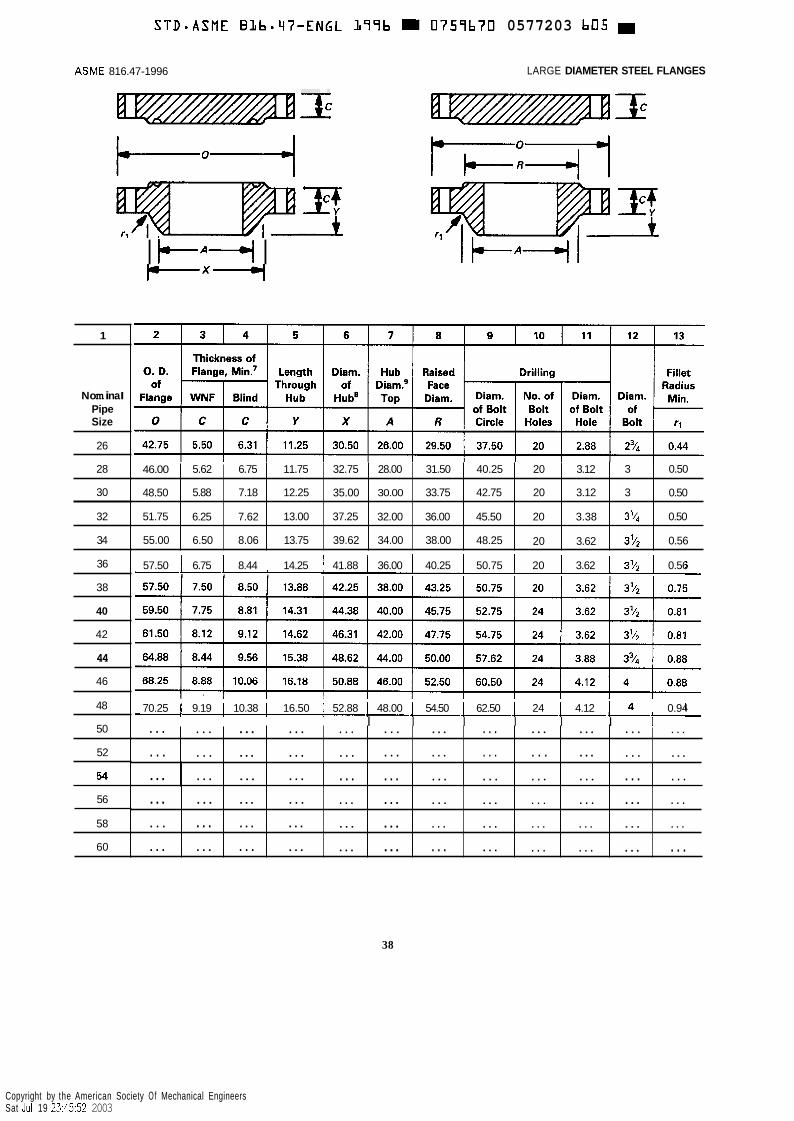
STD-ASME Blb.47-ENGL L97b M 0757b70 0577203 b05
46.00
48.50
51.75
55.00
5.62 6.75 11.75 32.75 28.00 31.50 40.25 20 3.12 3 0.50
5.88 7.18 12.25 35.00 30.00 33.75 42.75 20 3.12 3 0.50
6.25 7.62 13.00 37.25 32.00 36.00 45.50 20 3.38 3'14 0.50
6.50 8.06 13.75 39.62 34.00 38.00 48.25 20 3.62 372 0.56
. . .
. . . . . . ... . . . . . . . . . ... . . . . . . ... . . . . . .
. . . ... . . . . . . . . . . . . . . . . . . ... . . . ...
...
...
. . .
. . .
. . . ... . . . . . . ... . . . . . . . . . . . . . . . . . .
. .. ... . . . . . . . . . . . . . .. . . . . . . . . . . . .
. . . ... ... ... ... . . . . . . . . . . . . ... . . .
. . . . . . ... ... ... . . . . . . . . . . . . . . . . . .
ASME 816.47-1996 LARGE DIAMETER STEEL FLANGES
I FA+ I rx-I
1
No m i n a I Pipe Size
26
28
30
32
34
36 57.50 6.75 8.44 14.25 41.88 36.00 40.25 50.75 20 I 3.62 I 3'12 I 0.56 I I I
38
40
42
44
46
48 70.25 I 9.19 I 10.38 I 16.50 1 52.88 I 48.00 I 54.50 I 62.50 1 24 I 4.12 I 0.94 I I I I I I I 50
52
54
56
58
60
38
Copyright by the American Society Of Mechanical Engineers Sat Jul 19 23:45:52 2003
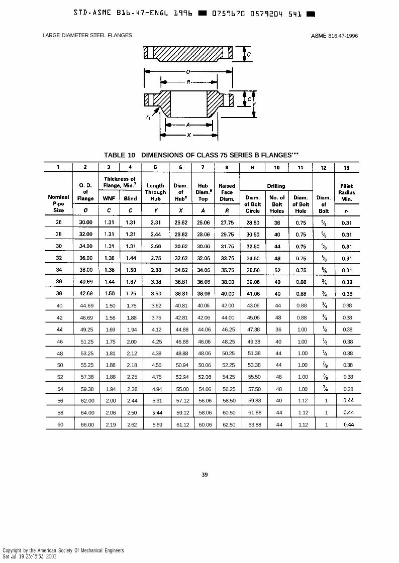
LARGE DIAMETER STEEL FLANGES ASME 816.47-1996
40
42
44
TABLE 10 DIMENSIONS OF CLASS 75 SERIES B FLANGES'"
~~
44.69 1.50 1.75 3.62 40.81 40.06 42.00 43.06 44 0.88 /a 0.38
46.69 1.56 1.88 3.75 42.81 42.06 44.00 45.06 48 0.88 /4 0.38
49.25 1.69 1.94 4.12 44.88 44.06 46.25 47.38 36 1.00 /8 0.38
46
48
50
52
54
~~~~
51.25 1.75 2.00 4.25 46.88 46.06 48.25 49.38 40 1.00 /a 0.38
53.25 1.81 2.12 4.38 48.88 48.06 50.25 51.38 44 1.00 ' /B 0.38
55.25 1.88 2.18 4.56 50.94 50.06 52.25 53.38 44 1.00 /B 0.38
57.38 1.88 2.25 4.75 52.94 52.06 54.25 55.50 48 1.00 7 / , 0.38
59.38 1.94 2.38 4.94 55.00 54.06 56.25 57.50 48 1.00 /A 0.38
56
58
62.00 2.00 2.44 5.31 57.12 56.06 58.50 59.88 40 1.12 1 0.44
64.00 2.06 2.50 5.44 59.12 58.06 60.50 61.88 44 1.12 1 0.44
39
60
Copyright by the American Society Of Mechanical Engineers Sat Jul 19 23:45:53 2003
66.00 2.19 2.62 5.69 61.12 60.06 62.50 63.88 44 1.12 1 0.44
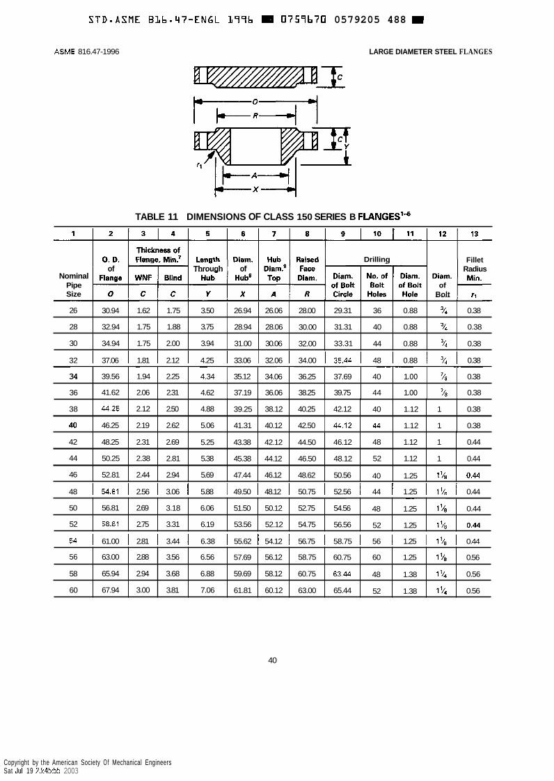
S T D - A S M E BLb.47-ENGL L79b E 0759b70 0579205 488
26
28
30
ASME 816.47-1996 LARGE DIAMETER STEEL FLANGES
~ ~~ ~~
30.94 1.62 1.75 3.50 26.94 26.06 28.00 29.31 36 0.88 % 0.38
32.94 1.75 1.88 3.75 28.94 28.06 30.00 31.31 40 0.88 7 4 0.38
34.94 1.75 2.00 3.94 31.00 30.06 32.00 33.31 44 0.88 "/4 0.38
TABLE 11 DIMENSIONS OF CLASS 150 SERIES B FLANGESlb
~
34
36
Nominal Pipe Size
~ ~ ~~~ ~~~ ~~ ~
39.56 1.94 2.25 4.34 35.12 34.06 36.25 37.69 40 1 .oo '/B 0.38
41.62 2.06 2.31 4.62 37.19 36.06 38.25 39.75 44 1 .oo '/s 0.38 I
of Through of
38
PO
0 I C I C I y I x
44.25 2.12 2.50 4.88 39.25 38.12 40.25 42.12 40 1.12 1 0.38
46.25 2.19 2.62 5.06 41.31 40.12 42.50 44.12 44 1.12 1 0.38
Drilling
42
44
46
Fillet Radius
of Bolt
~ ~~
48.25 2.31 2.69 5.25 43.38 42.12 44.50 46.12 48 1.12 1 0.44
50.25 2.38 2.81 5.38 45.38 44.12 46.50 48.12 52 1.12 1 0.44
52.81 2.44 2.94 5.69 47.44 46.12 48.62 50.56 40 1.25 178 0.44
50
52
32 I 37.06 I 1.81 I 2.12 I 4.25 I 33.06 I 32.06 I 34.00 I 35.44 I 48 1 0.88 I 3/, I 0.38
~~
56.81 2.69 3.18 6.06 51.50 50.12 52.75 54.56 48 1.25 178 0.44
58.81 2.75 3.31 6.19 53.56 52.12 54.75 56.56 52 1.25 11/8 0.44
56
58
60
~ ~~
63.00 2.88 3.56 6.56 57.69 56.12 58.75 60.75 60 1.25 1'18 0.56
65.94 2.94 3.68 6.88 59.69 58.12 60.75 63.44 48 1.38 194 0.56
67.94 3.00 3.81 7.06 61.81 60.12 63.00 65.44 52 1.38 174 0.56
48 I 54.81 I 2.56 I 3.06 I 5.88 I 49.50 I 48.12 I 50.75 I 52.56 I 44 I 1.25 I 1 k I 0.44
54 I 61.00 I 2.81 I 3.44 I 6.38 I 55.62 I 54.12 56.75 I 58.75 I 56 I 1.25 I 1k8 I 0.44
40
Copyright by the American Society Of Mechanical Engineers Sat Jul 19 23:45:55 2003

STD*ASME BLbm'i7-ENGL L 7 7 b 0757b70 057720b 314
Nominal Pipe Size
26
28
30
32
34
36
LARGE DIAMETER STEEL FLANGES ASME 816.47-1996
~ ~ ~~
Thickness of 0. D. Flange, Min? Length Diam. Hub Raised Drilling Fillet
of Through of Diam? Face Radius Flange WNF Blind Hub Hub8 Top Diam, Diam. NO. Of Diam. Diam. Mi".
0 c C Y X A R Circle Holes Hole Bolt rl
34.12 3.50 3.50 5.69 27.62 26.19 29.00 31.62 32 1.38 11/4 0.56
36.25 3.50 3.50 5.88 29.75 28.19 31.00 33.75 36 1.38 11/4 0.56
39.00 3.69 3.69 6.22 32.00 30.25 33.25 36.25 36 1.50 13/e 0.56
of Bolt Bolt of Bolt of
41.50 4.06 4.06 6.62 34.00 32.25 35.50 38.50 32 1.62 ll/z 0.62
43.62 4.06 4.06 6.81 36.12 34.25 37.50 40.62 36 1.62 1'12 0.62
46.12 4.06 4.06 7.12 38.00 36.25 39.75 42.88 32 1.75 178 0.62
TABLE 12 DIMENSIONS OF CLASS 300 SERIES B FLANGES'&
46
48
50
52
54
56
58
60
1 1 2 1 3 1 4 1 5 I S ] 7 1 8 1 9 1 10 I 11 I 12 I 13
57.50 5.06 5.12 8.75 48.38 46.31 50.00 53.75 36 2.00 178 0.62
59.50 5.06 5.31 8.81 50.31 48.31 52.25 55.75 40 2.00 17/s 0.62
61.50 5.44 5.50 9.25 52.38 50.31 54.25 57.75 44 2.00 i7i8 0.62
63.50 5.62 5.68 9.56 54.44 52.31 56.25 59.75 48 2.00 178 0.62
65.88 5.38 5.88 9.44 56.50 54.31 58.25 62.12 48 2.00 1'18 0.62
69.50 6.06 6.18 10.56 58.81 56.31 60.50 65.00 36 2.38 21/4 0.69
71.94 6.06 6.38 10.81 60.94 58.31 62.75 67.44 40 2.38 2'/4 0.69
73.94 5.94 6.56 10.69 62.94 60.31 65.00 69.44 40 2.38 21/4 0.69
41
Copyright by the American Society Of Mechanical Engineers Sat Jul 19 23:45:56 2003
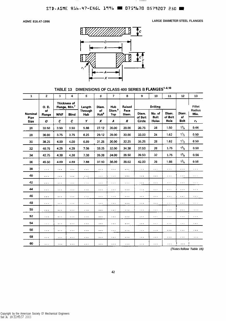
ASME 816.47-1996 LARGE DIAMETER STEEL FLANGES
TABLE 13 DIMENSIONS OF CLASS 400 SERIES B FLANGES'"#10
1 2 3 4 5 6 7 8 9 10 11 12 13
Fillet Radius
1.75 0.50
1.75 I 178 I 0.56
. + . . I . . .
. . . ! . . . I . . .
. . . I ... I
(Notes follow Table 15)
42
Copyright by the American Society Of Mechanical Engineers Sat Jul 19 23:45:57 2003
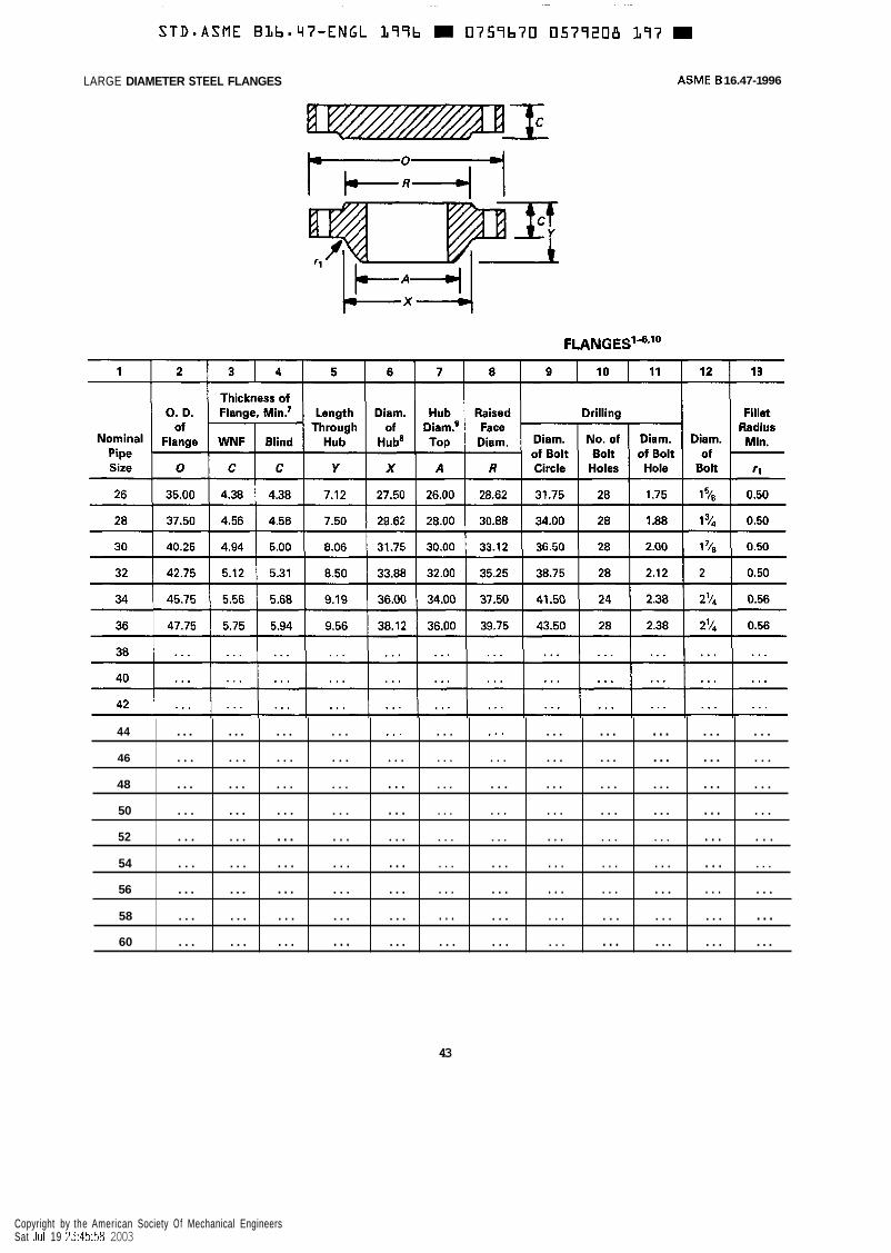
LARGE DIAMETER STEEL FLANGES ASME 6 16.47-1 996
44
46
48
50
52
54
56
58
60
... ... ... . . . . * . . . . , . . . . . ... ... ... .. .
. . . . . . . . . . . . . . . . . . . . . . . . ... ... ... . . .
... ... . . . . . . . . . . . . . . . . . . . . . ... ... . . .
. . . ... . . . . . . . . . . . . . . . . . . . . . ... ... . . .
. . . . . . ... . . . . . . . . . . . . . . . . . . . . . . . . . . .
. . . . .. . . . . . . . .. . . . . . . . . . . . . . . . . . . . . .
... ... ... . . . ... . . . . . . . . . . . . . . . . . . . . .
. . . ... . . . ... ... . . . . . . . . . . . . . . . . . . ...
... ... . . . . .. ... . . . . . . . . . . . . ... ... ...
43
Copyright by the American Society Of Mechanical Engineers Sat Jul 19 23:45:58 2003
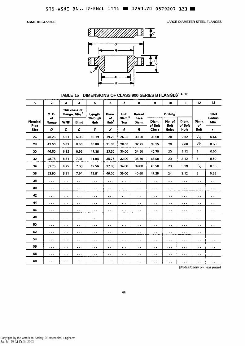
STD.ASME BLb.47-ENGL L79b 0759b70 0579207 023
ASME 816.47-1996 LARGE DIAMETER STEEL FLANGES
TABLE 15 DIMENSIONS OF CLASS 900 SERIES B FLANGES’4, lo
(Notes follow on next page)
44
Copyright by the American Society Of Mechanical Engineers Sat Jul 19 23:45:59 2003

S T D - A S M E BLb.V7-ENGL 177b = 0757b70 0577230 B ' i 5 B
LARGE DIAMETER STEEL FLANGES ASME 616.47-1996
Notes to Tables 5-15
GENERAL NOTE: Dimensions are in inches.
NOTES: (1) For tolerances, see Section 7. (2) For facings, see para. 6.1. (3) For flange bolt holes, see para. 6.2. (4) For spot facing, see para. 6.3. (5) The bore is to be specified by the purchaser. Tolerances in para. 7.4.2 apply. (6) Blind flanges may be made with or without hubs at the manufacturer's option. (7) When these flanges are required with flat face, either the full thickness or thickness with raised face removed may be furnished.
(8) This dimension is for the large end of hub, which may be straight or tapered. (9) For welding and bevel, see para. 6.4.
Users are reminded that removing the raised face will make the length through hub nonstandard.
(10) Dimensions for Classes 400, 600, and 900 NPS 38 and larger for Series B flanges are the same as for the Series A flanges.
45
Copyright by the American Society Of Mechanical Engineers Sat Jul 19 23:46:00 2003

~
STD*ASME BLbmq7-ENGL 177b 0757b70 U57721L 781
Maximum Radial Projection of Imperfections Which Are No Deeper Than the Bottom
of the Serration, in. Nominal Pipe Size
ASME 616.47-1996 LARGE DIAMETER STEEL FLANGES
Maximum Depth and Radial Projection of Imperfections Which Are Deeper Than the Bottom of the Serration, in.
26-36 3848 50-60
0.50 0.25 0.56 0.28 0.62 0.31
46
Copyright by the American Society Of Mechanical Engineers Sat Jul 19 23:46:01 2003

- -
S T D B A S M E B L b - W - E N G L L97b = 0759b70 0579232 bLB
ANNEX A
METHODS FOR ESTABLISHING PRESSURE-TEMPERATURE RATINGS
(This Annex is not part of ASME 816.47-1996 and is included for information only.)
A1 GENERAL
Al.1 Introduction
Pressure-temperature ratings in this Standard have been determined by the procedures in this Annex.
The primary consideration in establishing ratings is adequate wall thickness to sustain stresses due to pres- sure and other loadings. Other considerations affecting or limiting the ratings include:
(a) stresses in flanges resulting from bolt-up neces- sary to maintain gasket seal;
(6) distortion of flanges due to loadings transmitted through the pipeline; and
(c) limitations applying primarily to valves but im- posed also on flanges in order to maintain compatible ratings.
Al.2 Material Groups
Material groups in Table 1 are based on identical or closely matched allowable stress and yield strength values. Where they are not identical, the lower value has been applied.
Note that material groups are not numbered consecu- tively. Some groups are intended for use only in valves. See ASME B16.34.
Al.3 Material Properties
The allowable stress and yield strength values used to calculate the pressure-temperature ratings were taken from the ASME Boiler and Pressure Vessel Code, Section 11, Part D. In addition, data has been provided directly by the ASME Boiler and Pressure Vessel Subcommittee on Materials.
A2 RATINGS
A2.1 Rating Equation
Ratings given in Tables 2, psig at temperatures expressed in degrees Fahrenheit, for all materials and pressure classes, are established by Eq. (1):
where P, = rated working pressure, psig, for the specified
material at temperature T P, = pressure rating class index expressed in psi'
(e.g. P, = 300 psi for Class 300) S1 = selected stress, psi, for the specified material at
temperature T (see paras. A2.2, A2.3, and A2.4) P, = ceiling pressure, psig, as specified in A3 at
temperature T
A2.2 Ratings for Group 1 Materials, Class 300 and Higher
The selected stress S1 fore each material group among Group 1 materials in Table 1A is determined as follows.
(a) At temperatures below the creep range, S1 shall be lowest of the following values:
(I) 60% of specified minimum yield strength at 100°F;
(2) 60% of the yield strength at temperature T; (3) 1.25 times the alowable stress at temperature
T as listed for ASME BPV Code, Section I, or, if not listed for Section I, as listed for Section VIII Division 1.
(b) At temperatures in the creep range (defined as those above 700°F for Group 1 materials), S1 shall be the lowest of the following values:
( I ) 60% of the yield strength at temperature T; (2) the allowable stress at temperature T as listed
'This definition of P, does not apply to Class 75 and Class 150. See para. A2.4.
47
Copyright by the American Society Of Mechanical Engineers Sat Jul 19 23:46:02 2003
STD-ASME BLb*q7-ENGL L77b 0757b70 0579233 554
ASME B16.47-1996
for ASME BPV Code, Section I, as listed for
(c) In no case shall increasing temperature.
Section I, or, if not listed for Section VIII, Division 1. the value of S1 increase with
(d) Yikd strength values for determination of values of S1 shall be obtained from ASME BPV Code, Section 11, Part D.
(e) Where more than one allowable stress value is listed for a material at any temperature, the lower value shall be used. If lower allowable stress values do not appear, and it is noted in the allowable stress table that the allowable stress values exceed two-thirds of the yield strength at temperature, then the allowable stress values shall be determined as two-thirds of the tabulated yield strength at temperature.
lf3 Allowable stress values listed for the ASME BPV Code, Section 111, Class 2 and Class 3 may be used only if the material is not listed for either Section I or Section VIII, Division 1.
A2.3 Ratings for Group 2 Materials, Class 300
The selected stress S,, for each material group among Group 2 materials in Table 1A is determined as follows.
(a) At temperatures below the creep range, S1 is determined in accordance with para. A2.2(a), except that 70% of yield strength shall be used, instead of 60%, in paras. A2.2(a)(l) and (a)(2).
(b) At temperatures in the creep range (defined as those above 950°F for Group 2 materials), S , is deter- mined in accordance with para. A2.2(b).
(c) The limitations in paras. A2.2(c), (d), (e), and
and Higher
(0 apply.
LARGE DIAMETER STEEL FLANGES
A2.4 Ratings for Classes 75 and 150, All Material Groups
Pressure-tempexature ratings for Classes 75 and 150 flanges are determined for each material group as set forth in paras: A2.1, A2.2, and A2.3 with the following exceptions.
(a) The value of P, in Eq. (1) (para A2.1) shall be 57.5 psi for Class 75 and 115 psi for Class 150.
(b) The value for SI shall be in accordance with the requirements of paras. A2.1, A2.2, and A2.3.
(c) The value for PT in Eq. (1) at temperature T (degrees Fahrenheit) shall not exceed that given by Eqs. (2) and (3).
For Class 75
For Class 150
P T = 320 - 0.3T (3)
The limits of T in equation (2) and (3) are 100°F min. and 1000°F max. For values of T less than 100"F, T equal to 100°F is used.
A3 MAXIMUM RATINGS
A3.1 Maximum Ratings
A set of maximum or ceiling pressure-temperature ratings, Pc, are shown in Table Al . They are imposed to limit deflections.
48
Copyright by the American Society Of Mechanical Engineers Sat Jul 19 23:46:03 2003
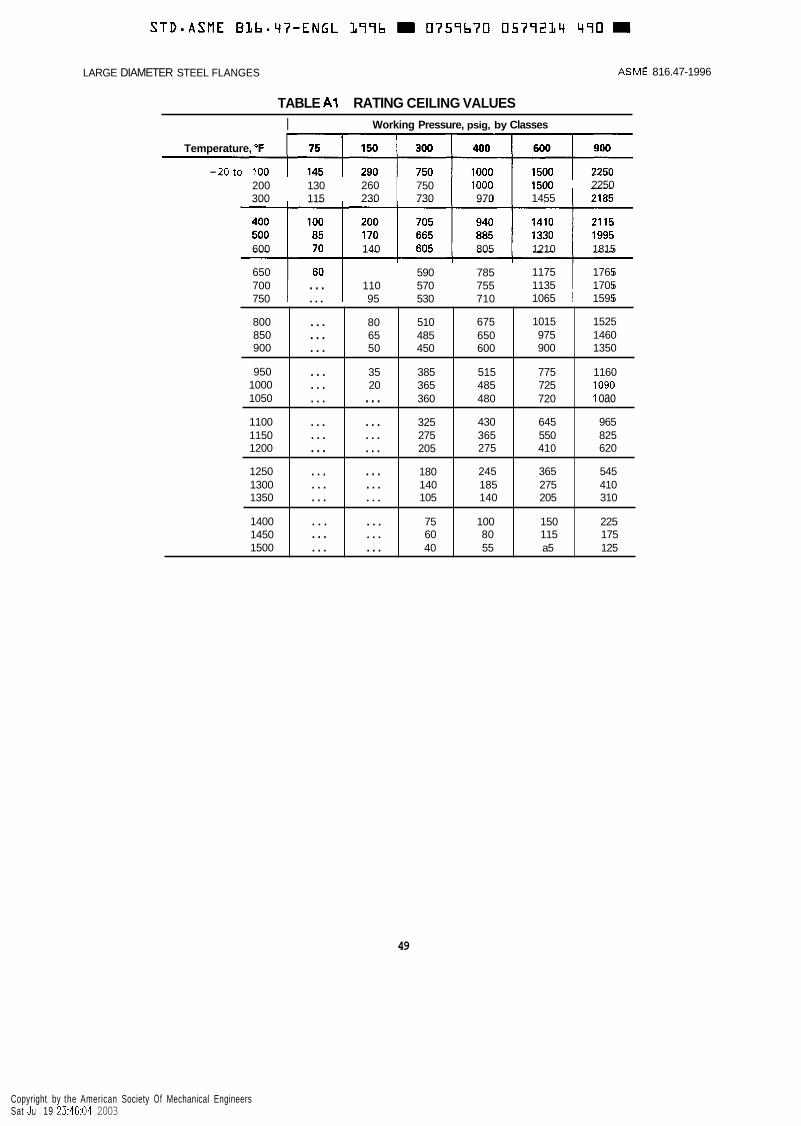
LARGE DIAMETER STEEL FLANGES ASME 816.47-1996
800 850 900
950 1000 1050
1100 1150 1200
1250 1300 1350
1400 1450 1500
TABLE A1 RATING CEILING VALUES
~ ___
... 80 510 675 1015 1525
... 65 485 650 975 1460
... 50 450 600 900 1350
... 35 385 515 775 1160
... 20 365 485 725 1090
... ... 360 480 720 i oao
... ... 325 430 645 965
... ... 275 365 550 825
... ... 205 275 41 0 620
... ... 180 245 365 545
... ... 140 185 275 410
... ... 105 140 205 310
. . . ... 75 100 150 225
... ... 60 80 115 175
... ... 40 55 a5 125
I Working Pressure, psig, by Classes
Temperature, O F
-20to 100 200 130 260 750 1000 300 115 230 730 970
2250 1455
600 140 805 1210 1815
650 590 785 1175 1765 700 ... 110 570 755 1135 1705 750 ... 95 530 710 1065 1595
49
Copyright by the American Society Of Mechanical Engineers Sat Jul 19 23:46:04 2003

~ ~
STD*ASME BL b m q 7 - E N G L L77b 0757b70 0579235 327 = LARGE DIAMETER STEEL FLANGES ASME B16.47- 1996
ANNEX B
GASKETS (Other Than Ring-Joint)
(This Annex is an integral part of ASME 816.47-1996 and is placed after the main text for convenience.)
B1 SCOPE
This Annex covers gasket characteristics.
B2 GASKET MATERIALS AND CONSTRUCTION
Classification of gasket materials and types is shown in Fig. B1. Other gaskets, which result in no increase in bolt loads or flange moment over those resulting from the gas- kets included in the respective groups in this Appendix, may be used and warrant the ratings of this Standard with the limiting dimensions of the applicable group. See also para. 5.4 for application of gaskets.
B3 GASKET DIMENSIONS
(a) The actual dimensions of a gasket must be
established by the user. Reference to a dimensional standard for gaskets, such as ASME B16.21 and ASME B16.20 is recommended. In any case, selected dimen- sions should be based on the type of gasket and its characteristics. These characteristics include its density, flexibility, resistance to the fluid and its temperature, and the necessity for satisfactorily compressing the gasket on its I.D., its O.D., or both. Also to be considered is the question of allowing a “pocket” at the gasket I.D. (between the flange facings) or of allowing any intrusion of the gasket into the flange bore. Consideration should be given to the service fluid as well as to the possibility of damage which might result from partially disintegrated gaskets.
(b) Gaskets are divided into three groups based on their gasket loading factors as shown in the ASME BPV Code, Section VIII, Division 1, Pressure Vessels.
51
Copyright by the American Society Of Mechanical Engineers Sat Jul 19 23:46:05 2003

STDmASME BLb.47-ENGL 1996 0759b70 05792Lb 2b3
ASME B16.47-1996 LARGE DIAMETER STEEL FLANGES
Gasket Group Number Gasket Material
Ib
Spiral-Wound Metal, With Nonmetallic Fiber
Corrugated Aluminum, Copper or Copper Alloy or Corrugated Aluminum, Copper or Copper Alloy Double Jacketed With Nonmetallic Filler
Sketches
Self-Energizing Types O-rings, metallic, elastomer, other gasket types considered as self-sealing
Elastomer Without Fabric
. . .
la I Compressed Sheet Suitable for the Operating Conditions
Elastomer With Cotton Fabric Insertion
Elastomer With or Without Wire Reinforcement ~~
Vegetable Fiber
Corrugated Aluminum, Copper, or Brass
Corrugated Metal or Corrugated Metal Double Jacketed With Nonmetallic Fiber
Corrugated Metal
Ila and Ilb
Flat Metal Jacketed With Nonmetallic Fiber
1 Grooved Metal
I Solid Flat Soft Aluminum
Illa Solid Flat Metal and I lllb
. . . I Ring-Joint . . .
FIG. B1 GASKET GROUPS AND TYPICAL MATERIALS
52
Copyright by the American Society Of Mechanical Engineers Sat Jul 19 23:46:06 2003
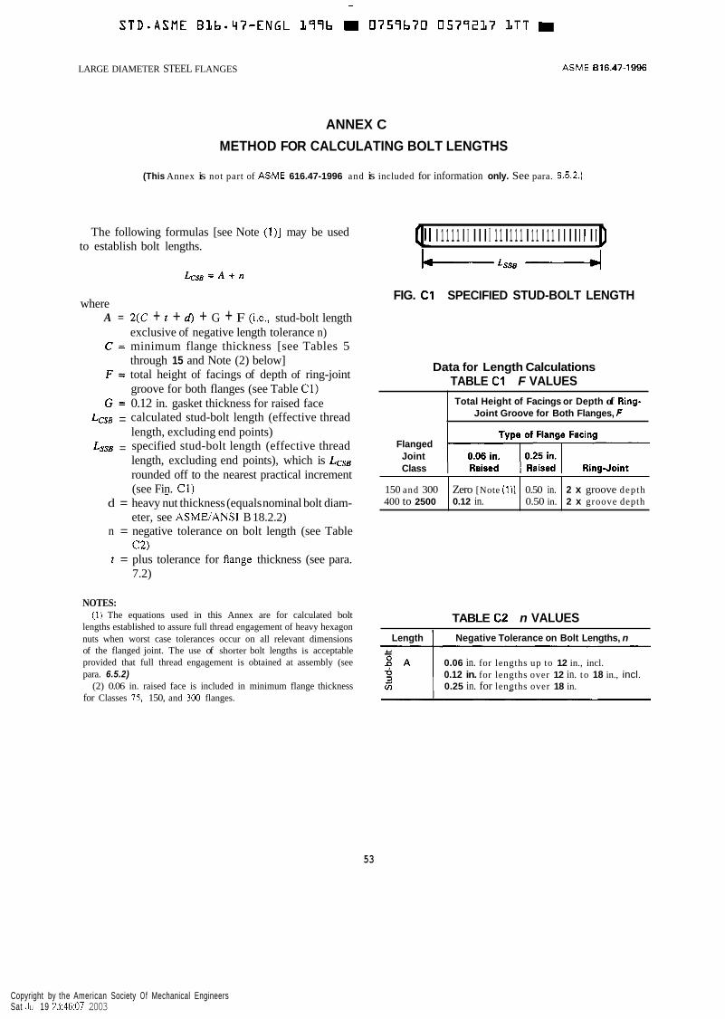
~
S T D - A S M E BLb.47-ENGL L97b 0757670 0577237 LTT
150 and 300 400 to 2500
LARGE DIAMETER STEEL FLANGES
Zero [Note (111 0.50 in. 2 x groove depth 0.12 in. 0.50 in. 2 x groove depth
ANNEX C
METHOD FOR CALCULATING BOLT LENGTHS
ASME 016.47-1996
(This Annex is not part of ASME 616.47-1996 and is included for information only. See para. 6.5.2.)
The following formulas [see Note (l)] may be used to establish bolt lengths.
where A =
C =
F =
G = LCSB =
LSSB =
2(C + t + d) + G + F (i.e., stud-bolt length exclusive of negative length tolerance n) minimum flange thickness [see Tables 5 through 15 and Note (2) below] total height of facings of depth of ring-joint groove for both flanges (see Table C1) 0.12 in. gasket thickness for raised face calculated stud-bolt length (effective thread length, excluding end points) specified stud-bolt length (effective thread length, excluding end points), which is Less rounded off to the nearest practical increment (see Fin. C1) -
d = heavy nut thickness (equals nominal bolt diam-
n = negative tolerance on bolt length (see Table
r = plus tolerance for flange thickness (see para.
eter, see ASMWANSI B 18.2.2)
C2)
7.2)
NOTES: (1) The equations used in this Annex are for calculated bolt
lengths established to assure full thread engagement of heavy hexagon nuts when worst case tolerances occur on all relevant dimensions of the flanged joint. The use of shorter bolt lengths is acceptable provided that full thread engagement is obtained at assembly (see para. 6.5.2)
(2) 0.06 in. raised face is included in minimum flange thickness for Classes 75. 150, and 300 flanges.
QI I 1 1 1 1 I I I I I I 1 1 I 1 1 1 I 1 1 I 1 1 I I I I 1 1 I ID L L s s e ,I
FIG. C1 SPECIFIED STUD-BOLT LENGTH
Data for Length Calculations TABLE C1 F VALUES Total Height of Facings or Depth of Ring-
Joint Groove for Both Flanges, F
Flanged Joint Class
TABLE C2 n VALUES Length Negative Tolerance on Bolt Lengths, n
0.06 in. for lengths up to 12 in., incl. 0.12 in. for lengths over 12 in. to 18 in., incl. 0.25 in. for lengths over 18 in.
53
Copyright by the American Society Of Mechanical Engineers Sat Jul 19 23:46:07 2003

- ~
S T D - A S M E BLb*qT-ENGL 399b 0759b70 0577238 03b W
LARGE DIAMETER STEEL FLANGES ASME 816.47-1996
ANNEX D
QUALITY SYSTEM PROGRAM
(This Annex is an integral part of ASME 816.47.1996 and is placed after the main text for convenience.)
The products manufactured in accordance with this Standard shall be produced under a quality system program following the principles of an appropriate standard from the IS0 9000 series.’ A determination of the need for registration and/or certification of the
’The series is also available from the American National Standards Institute (ANSI) and the American Society for Quality Control (ASQC) as American National Standards that are identified by a prefix “Q’ replacing the prefix “ISO”. Each standard of the series is listed under Annex E.
product manufacturer’s quality system program by an independent organization shall be the responsibility of the manufacturer. The detailed documentation demon- strating program compliance shall be available to the purchaser at the manufacturer’s facility. A written sum- mary description of the program utilized by the product manufacturer shall be available to the purchaser upon request. The product manufacturer is defined as the entity whose name or trademark appears on the product in accordance with the marking or identification require- ments of this Standard.
55
Copyright by the American Society Of Mechanical Engineers Sat Jul 19 23:46:08 2003
S T D * A S M E BLb.47-ENGL L79b W 0757b70 0579237 T72 = LARGE DIAMETER STEEL FLANGES ASME 616.47-1996
ANNEX E REFERENCES
(This Annex is an integral part of ASME 616.47.1996 and is placed after the main text for convenience.)
The following is a list of standards and specifications referenced in this Standard, showing the year of approval. Products covered by each ASTM specification are listed for convenience. (See specifications for exact titles and detailed contents.)
API Publications API Standard 605-1988
ASME Publications ASME B1.l-1989 ASME B 1.20.1-1983(R1992) ASME B 16.20- 1993 ASME B16.21-1992 ASME B16.34-1996 ASME B 18.2.1- 198 1 (R 1992) ASME B 18.2.2-1987(R1993) ASME B31.3-1992 ASME B36.10M-1985 ANSUASME B46.1-1985
Large-Diameter Carbon Steel Flanges
Unified Inch Screw Threads (UN and UNR Thread Form) Pipe Threads, General Purpose (Inch) Metallic Gaskets for Pipe Flanges - Ring-Joint, Spiral-Wound, and Jacketed Nonmetallic Flat Gaskets for Pipe Flanges Valves - Flanged, Threaded, and Welding End Square and Hex Bolts and Screws, Inch Series Square and Hex Nuts (Inch Series) Chemical Plant and Petroleum Refinery Piping Welded and Seamless Wrought Steel Pipe Surface Texture (Surface Roughness, Waviness, and Lay)
ASME Boiler and Pressure Vessel Code, 1995 Edition (Including Addenda Through 1995) Section I Power Boilers Section I1 Materials Section I11 Section VIII, Div. 1 & 2
Nuclear Power Plant Components Pressure Vessels
International Standards Organization (SO) IS0 9000-1: 1994
IS0 9000-2: 1993
IS0 9000-3: 1991
IS0 9001: 1994
IS0 9002: 1994 IS0 9003: 1994
Quality management and quality assurance standards - Part 1 : Guidelines for selec- tion and use Quality management and quality assurance standard - Part 2: Generic guidelines for the application of IS0 9001, IS0 9002, and IS0 9003 Quality management and quality assurance standards - Part 3: Guidelines for the application of IS0 9001 to the development, supply and maintenance of software Quality systems - Model for quality assurance in design, development, production, installation, and servicing Quality systems - Model for quality assurance in production and servicing Quality systems - Model for quality assurance in final inspection and test
57
Copyright by the American Society Of Mechanical Engineers Sat Jul 19 23:46:09 2003

S T D - A S M E
ASME B 16.47- 1996
ASTM Publications A 105-93b A 182-93b
A 193-93a A 194-93a
A 203-93 A 204-93 A 216-89 A 217-91
A 240-93b
A 307-93a A 320-93 A 350-93
A 351-93 A 352-92
A 354-93
A 387-92'' A 449-93 A 453-92
A 515-92
A 5 16-90 A 537-91 A 540-92 E 29-93
MSS Publications MSS SP-9-1992 MSS SP-25-1978(R1983,R1988) MSS SP-44-1991 MSS SP-45-1992 MSS SP-61-1992
B L b - q 7 - E N G L L77b m 0757b70 0577220 77q m
LARGE DIAMETER STEEL FLANGES
Forgings, Carbon Steel, for Piping Components Forged or Rolled Alloy Steel Pipe Flanges, Forged Fittings, and Valves and Parts for High Temperature Service Alloy-Steel and Stainless Steel Bolting Materials for High-Temperature Service Carbon and Alloy Steel Nuts for Bolts for High-Pressure and High-Temperature Service Pressure Vessel Plates, Alloy Steel, Nickel Pressure Vessel Plates, Alloy Steel, Molybdenum Steel Castings, Carbon, Suitable for Fusion Welding, for High-Temperature Service Steel Castings, Martensitic Stainless and Alloy, for Pressure-Containing Parts, Suitable for High-Temperature Service Heat-Resisting Chromium and Chromium-Nickel Stainless Steel Plate, Sheet, and Strip for Pressure Vessels Carbon Steel Bolts and Studs, 60,000 psi Tensile Strength Alloy-Steel Bolting Materials for Low-Temperature Service Forgings, Carbon and Low-Alloy Steel, Requiring Notch Toughness Testing for Piping Components Steel Castings, Austenitic, Austenitic-Femtic (Duplex), for Pressure-Containing Parts Steel Castings, Femtic and Martensitic, for Pressure-Containing Parts, Suitable for Low-Temperature Service Quenched and Te-mpered Alloy Steel Bolts, Studs, and Other Externally Threaded Fasteners Pressure Vessel Plates, Alloy Steel, Chromium-Molybdenum Quenched and Tempered Steel Bolts and Studs Bolting Materials, High-Temperature, 50 to 120 ksi [345 to 827 MPa] Yield Strength, With Expansion Coefficients Comparable to Austenitic Steels Pressure Vessel Plates, Carbon Steel, for Intermediate- and Higher-Temperature Service Pressure Vessel Plates, Carbon Steel, For Moderate- and Lower-Temperature Service Pressure Vessel Plates, Heat-Treated, Carbon-Manganese-Silicon Steel Alloy-Steel Bolting Materials for Special Applications Using Significant Digits in Test Data to Determine Conformance with Specifications
Spot-Facing for Bronze, Iron, and Steel Flanges Standard Marking System for Valves, Fittings, Flanges, and Unions Steel Pipe Line Flanges Bypass and Drain Connection Pressure Testing of Steel Valves
Publications of the following organizations appear in the above list:
API
American Society for Quality Control P.O. Box 3005 Milwaukee, WI 53201-3005
American Petroleum Institute 1220 L Street, N.W., Washington, D.C. 20005
58
Copyright by the American Society Of Mechanical Engineers Sat Jul 19 23:46:10 2003

S T D S A S M E Blb-47-ENGL 377b 0757b70 0579223 b20
LARGE DIAMETER STEEL FLANGES ASME B16.47-1996
ASME
ASTM
MSS
The American Society of Mechanical Engineers 345 East 47th Street, New York, New York 10017-2392
ASME Order Department 22 Law Drive, Box 2300, Fairlield, New Jersey 07007-2300
American Society for Testing and Materials 1916 Race Street, Philadelphia, Pennsylvania 19103
Manufacturers Standardization Society of the Valve & Fittings Industry 127 Park Street, N.E., Vienna, Virginia 22180
IS0 documents are available from ANSI. Publications appearing above which have been approved as American National Standards may also be obtained from ANSI.
ANSI American National Standards Institute, Inc. 11 West 42nd St., New York, New York 10036
59
Copyright by the American Society Of Mechanical Engineers Sat Jul 19 23:46:11 2003