printing characters and symbols indicates a...
TRANSCRIPT

REV. 01 2 / 32
PRINTING CHARACTERS AND SYMBOLS
Throughout this manual, the following symbols and printing characters are used to facilitate reading:
Indicates the operations which need proper care
Indicates prohibition
Indicates a possibility of danger for the operators
BOLD TYPE Important information
WARNING: before operating the lift and carrying out any adjustment, read carefully chapter 7 “installation” where all proper operations for a better functioning of the lift are shown.

REV. 01 3 / 32
CONTENTS
1 INTRODUCTION 41.1 - INTRODUCTION 1.2 MACHINE IDENTIFICATION DATA 1.3 MANUAL KEEPING
444
2 GENERAL INFORMATION 52.1 INTENDED USE2.2 GENERAL SAFETY PRECAUTIONS2.3 SAFETY DEVICES 2.4 PRODUCT DESCRIPTION 2.5 TECHNICAL SPECIFICATION
55567
3 TRANSPORTATION, UNPACKING AND STORAGE 83.1 TRANSPORTATION 3.2 UNPACKING 3.3 STORAGE
888
4 INSTALLATION 94.1 INSTALLATION SPACE REQUIRED 4.2 WORKPLACE REQUIRED 4.3 FOUNDATION REQUIREMENT 4.4 ELECTRIC CONNECTION
9910 11
5 OPERATION 12 5.1 CONTROLS 5.2 WORKING POSITION 5.3 CORRECT OPERATION CHECKS 5.4 LOCKING THE WHEEL 5.5 TUBELESS AND SUPERSINGLE WHEELS 5.6 TUBED WHEELS 5.7 WHEELS WITH SPLIT RING
12 12 13 14 16 20 23
6 ORDINARY MAINTENANCE 27
7 TROUBLE SHOOTING 28
8 MOVING, STORING AND SCRAPPING 8.1 MOVING THE MACHINE 8.2 STORING 8.3 SCRAPPING A MACHINE
29 29 29 29
9 OPTIONAL ACCESSORIES 30
10 HYDRAULIC SCHEME AND ELECTRIC DIAGRAM 31
REV. 01 4 / 32
CHAPTER 1 – INTRODUCTION
1.1 INTRODUCTION
Thank you for purchasing a product from the line of truck tire changers. The machine has been manufactured in accordance with the very best quality principles. Follow the simple instructions provided in this manual to ensure the correct operation and long life of the machine. Read the entire manual thoroughly and make sure you understand it.
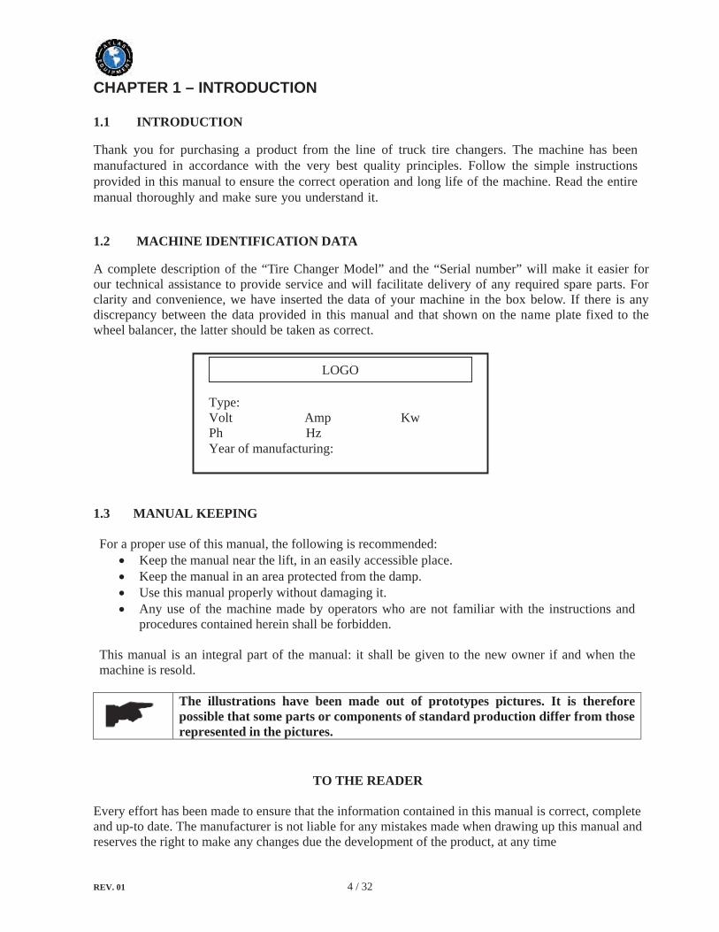
1.2 MACHINE IDENTIFICATION DATA
A complete description of the “Tire Changer Model” and the “Serial number” will make it easier for our technical assistance to provide service and will facilitate delivery of any required spare parts. For clarity and convenience, we have inserted the data of your machine in the box below. If there is any discrepancy between the data provided in this manual and that shown on the name plate fixed to the wheel balancer, the latter should be taken as correct.
1.3 MANUAL KEEPING
For a proper use of this manual, the following is recommended: Keep the manual near the lift, in an easily accessible place. Keep the manual in an area protected from the damp. Use this manual properly without damaging it. Any use of the machine made by operators who are not familiar with the instructions and procedures contained herein shall be forbidden.
This manual is an integral part of the manual: it shall be given to the new owner if and when the machine is resold.
The illustrations have been made out of prototypes pictures. It is therefore possible that some parts or components of standard production differ from those represented in the pictures.
TO THE READER
Every effort has been made to ensure that the information contained in this manual is correct, complete and up-to date. The manufacturer is not liable for any mistakes made when drawing up this manual and reserves the right to make any changes due the development of the product, at any time
LOGO
Type: Volt Amp Kw Ph Hz Year of manufacturing:

REV. 01 5 / 32
CHAPTER 2 – GENERAL INFORMATION
2.1 INTENDED USE
This tire changer has been designed and manufactured exclusively for removing and mounting truck, bus and commercial van tires from/onto rims from 14" to 56" and a maximum diameter of 2300mm.In particular THE MANUFACTURER cannot be held responsible for any damage caused through the use of this tire changer for purposes other than those specified in this manual, and therefore inappropriate, incorrect and unreasonable.
2.2 GENERAL SAFETY PRECAUTIONS
The machine should only be used by duly authorized and trained personnel. The machine should not be used for purposes other than those described in the instruction manual. Under no way should the machine be modified except for those modifications made explicitly by THE MANUFACTURER.Never remove the safety devices. Any work on the machine should only be carried out by specialist personnel. Any tampering or modification to the equipment carried out without the manufacturer’s prior authorization will free him from all responsibility for damage caused directly or indirectly by the above actions.Removing or tampering with safety devices immediately invalidates the guarantee.The tire changer comes complete with instruction and warning transfers which are designed to be long-lasting. If they should for any reason be damaged or destroyed, please ask immediately for replacements from the manufacturer.The machine operator should avoid wearing clothes with flapping edges. Make sure that unauthorized personnel do not approach the machine during the work cycle.
2.3 SAFETY DEVICES
The tire changer has a number of safety devices designed to guarantee the upmost safety:
Check valve on the spindle opening hydraulic line (inside the swivel connector, see fig. B/1). This prevents the wheel from falling from the spindle if the hydraulic line is accidentally broken. Pressure relief valve set at 130 bar ± 10% (see fig. B/2). This limits the pressure in the hydraulic line and ensures correct operation of the plant. Pump motor overload cut-off (inside the electric enclosure). This cuts if the motor overheats to prevent it from burning out. Check valve on the chuck arm lifting hydraulic line.It prevents the chuck arm from descending when any accidental break occurs in the hydraulic line. .

REV. 01 6 / 32
2.4 PRODUCT DESCRIPTION
1. Lifting bracket 2. Self-centering chuck holding arm 3. Self-centering chuck 4. Sliding table 8. Joystick9. Switch10. Pedal
13. Carriage 14. Tool holding arm 15. Arm lever 17. Bead breaking disk 18. Tool 19. Pedal 22. Jaw
During all operations, keep hands and other parts of the body as far as possible from any moving part of the machine. Necklaces, bracelets and too large cloths, can be dangerous for the operator.

REV. 01 7 / 32
2.5 TECHNICAL SPECIFICATION
Pump motor 1.1kw Gear-box motor 1.3kw/1.8kw (3 ph double speed) Handles rim from 14” – 56” Max. tire diameter 2300mm Max. tire width 1065mm Max. wheel weight 1500 kg Net weight 770 kgNoise level in working condition < 70 dB (A)
2.6 WARNING SIGNS
Unreadable and missing warning labels must be replaced immediately. Do not use and add any object that could prevent the operator from seeing the labels.
REV. 01 8 / 32
CHAPTER 3 – TRANSPORTATION, UNPACKING AND STORAGE
3.1 TRANSPORTATION
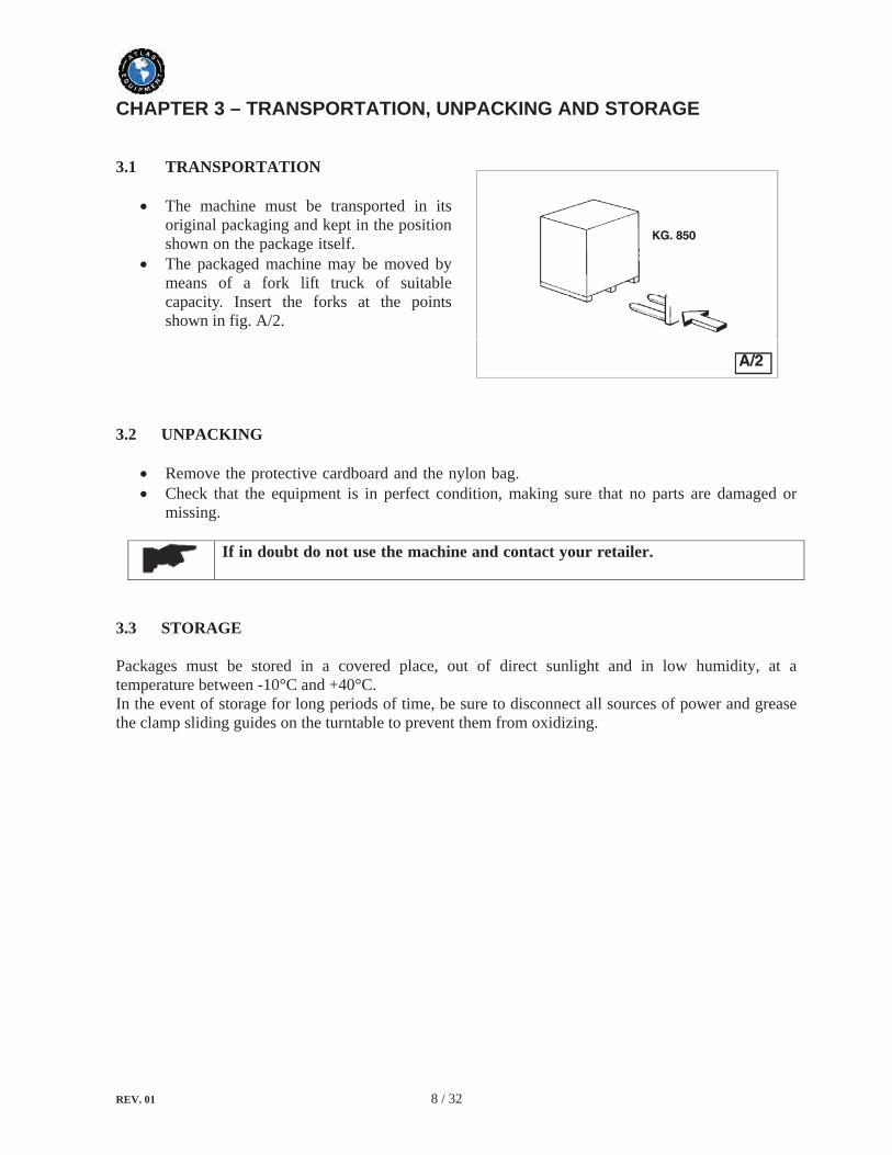
The machine must be transported in its original packaging and kept in the position shown on the package itself.The packaged machine may be moved by means of a fork lift truck of suitable capacity. Insert the forks at the points shown in fig. A/2.
3.2 UNPACKING
Remove the protective cardboard and the nylon bag.Check that the equipment is in perfect condition, making sure that no parts are damaged or missing.
If in doubt do not use the machine and contact your retailer.
3.3 STORAGE
Packages must be stored in a covered place, out of direct sunlight and in low humidity, at a temperature between -10°C and +40°C.In the event of storage for long periods of time, be sure to disconnect all sources of power and grease the clamp sliding guides on the turntable to prevent them from oxidizing.
REV. 01 9 / 32
CHAPTER 4 – INSTALLATION
4.1 INSTALLATION SPACE REQUIRED
When choosing the place of installation, make sure that it complies with current safety at work regulations.
The machine must be located on a flat floor of solid construction, preferably concrete. If the floor is uneven or broken, the machine will be not stable and the platform roller cannot move freely.If the machine is installed outside it must be protected by a lean-to.The following work environment conditions are applicable:- Relative humidity from 30-95% without condensation;- Temperature from 0-55°C.
4.2 WORKPLACE REQUIRED
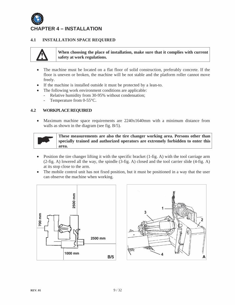
Maximum machine space requirements are 2240x1640mm with a minimum distance from walls as shown in the diagram (see fig. B/5).
These measurements are also the tire changer working area. Persons other than specially trained and authorized operators are extremely forbidden to enter this area.
Position the tire changer lifting it with the specific bracket (1-fig. A) with the tool carriage arm (2-fig. A) lowered all the way, the spindle (3-fig. A) closed and the tool carrier slide (4-fig. A) at its stop close to the arm.The mobile control unit has not fixed position, but it must be positioned in a way that the user can observe the machine when working.

REV. 01 10 / 32
4.3 FOUNDATION REQUIREMENT
The tire changer should be installed on a leveled concrete floor at least 20cm thick with a minimum concrete quality of B25 in accordance with DIN 1045 requirements (foundations). For your reference see the drawings as well as the table below.
If a floor of this type is not available on site, fastening points of the specified concrete quality are acceptable.
Surface, on which the tire changer is to be installed, must be flat and well leveled in all directions.Inclination up to 0.25% relative to the horizontal can be compensated using suitable shims, wedges or the alike.
When working with wheels, which weight is higher than 1000kg, it is necessary to fasten the tire changer to the floor by means of proper anchor bolts.
By means of a hammer drill D.16, drill at least 130mm into the floor passing through the holes provided on the base frame.If there is an additional floor covering (B), of if shims or wedges are necessary for leveling (C), longer bolts must be used.Place an anchor bolt into each hole.Make sure the anchor bolts extend at least 125mm into the concrete slab, as indicated in the drawings.
REV. 01 11 / 32
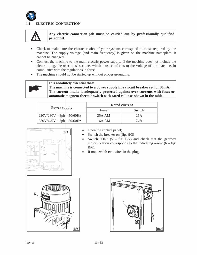
4.4 ELECTRIC CONNECTION
Any electric connection job must be carried out by professionally qualified personnel.
Check to make sure the characteristics of your systems correspond to those required by the machine. The supply voltage (and main frequency) is given on the machine nameplate. It cannot be changed. Connect the machine to the main electric power supply. If the machine does not include the electric plug, the user must set one, which must conforms to the voltage of the machine, in compliance with the regulations in force.The machine should not be started up without proper grounding.
It is absolutely essential that: The machine is connected to a power supply line circuit breaker set for 30mA. The current intake is adequately protected against over currents with fuses or automatic magneto-thermic switch with rated value as shown in the table.
Power supply Rated current
Fuse Switch 220V/230V – 3ph – 50/60Hz 25A AM 25A380V/440V – 3ph – 50/60Hz 16A AM 16A
Open the control panel;Switch the breaker on (fig. B/3)Switch “ON” (5 – fig. B/7) and check that the gearbox motor rotation corresponds to the indicating arrow (6 – fig. B/6).If not, switch two wires in the plug.
B/3
REV. 01 12 / 32
CHAPTER 5 – OPERATION
5.1 CONTROLS
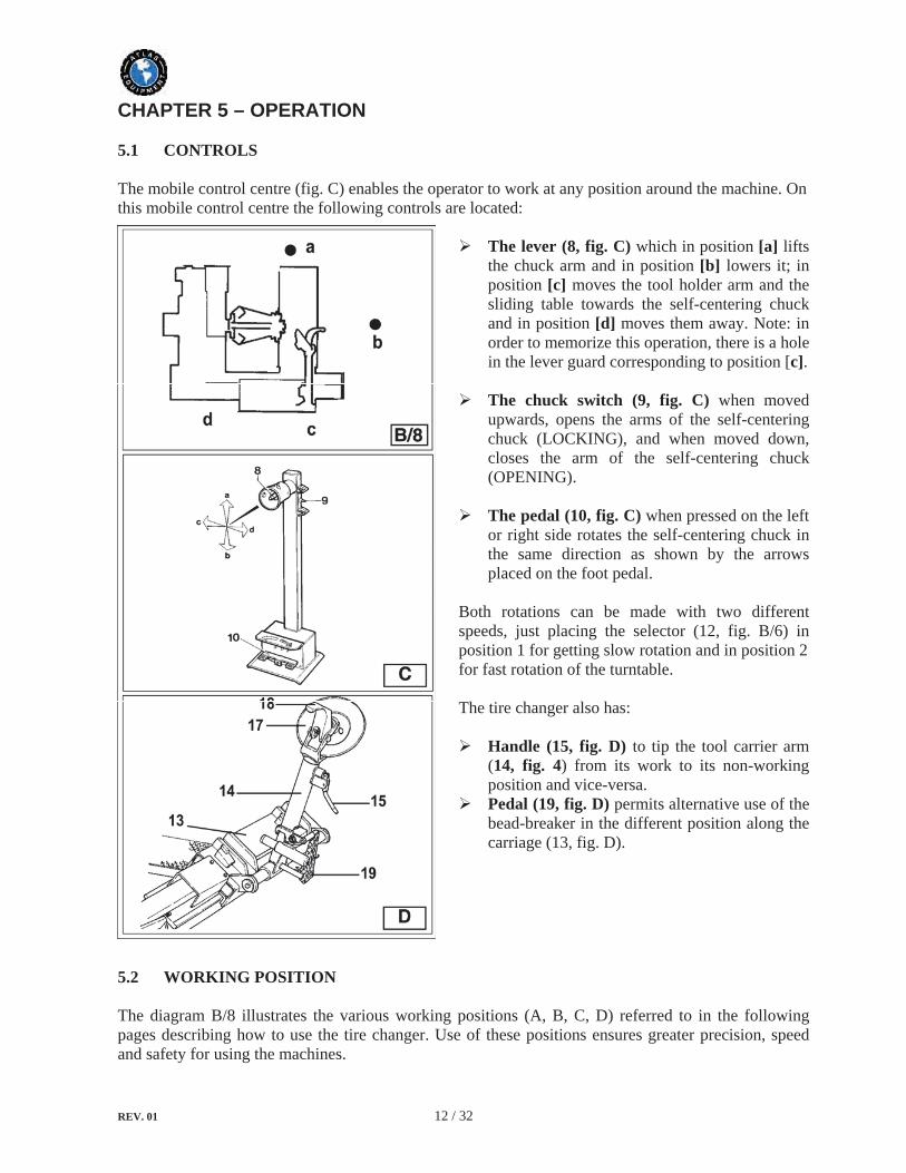
The mobile control centre (fig. C) enables the operator to work at any position around the machine. On this mobile control centre the following controls are located:
The lever (8, fig. C) which in position [a] liftsthe chuck arm and in position [b] lowers it; in position [c] moves the tool holder arm and the sliding table towards the self-centering chuck and in position [d] moves them away. Note: in order to memorize this operation, there is a hole in the lever guard corresponding to position [c].
The chuck switch (9, fig. C) when moved upwards, opens the arms of the self-centering chuck (LOCKING), and when moved down, closes the arm of the self-centering chuck (OPENING).
The pedal (10, fig. C) when pressed on the left or right side rotates the self-centering chuck in the same direction as shown by the arrows placed on the foot pedal.
Both rotations can be made with two different speeds, just placing the selector (12, fig. B/6) in position 1 for getting slow rotation and in position 2 for fast rotation of the turntable.
The tire changer also has:
Handle (15, fig. D) to tip the tool carrier arm (14, fig. 4) from its work to its non-working position and vice-versa. Pedal (19, fig. D) permits alternative use of the bead-breaker in the different position along the carriage (13, fig. D).
5.2 WORKING POSITION
The diagram B/8 illustrates the various working positions (A, B, C, D) referred to in the following pages describing how to use the tire changer. Use of these positions ensures greater precision, speed and safety for using the machines.

REV. 01 13 / 32
5.3 CORRECT OPERATION CHECKS
Before use the tire changer, a number of checks should be made to ensure it works correctly,
The operation described here should be done with the tool carrier arm in its non-working position.
First, use handle (15, fig. D) to tip the arm to this position,
1) Move the joystick (8, fig. C) up (a): the spindle carrier arm (2, Fig. A) should lift; move the joystick down (b): the arm should lower.
Move the joystick towards the left(c): the tool carriage and the mobile platform (13, fig. D) should move towards the spindle (3, fig. A); move the joystick towards the right (d) the carriage and platform should move away from the spindle.
2) Turn switch lever (9, fig. C) towards the top: the spindle arms (3, fig. A) should open; move the lever down and the spindle arms should close.
3) Depress the right pedal (10, fig. C): the spindle (2, fig. A) should turn clockwise; depress the left pedal: the spindle (2, fig. A) should turn anticlockwise.
4) Check to be certain the hydraulic circuit is working correctly:Move switch lever (9, fig. C) towards the top until the spindle arms are fully extended. Hold the switch lever in this position (top) and check if the pressure shown on the gauge on the swivel fitting is 130bar 10%. DO NOT USE THE MACHINES IF THE PRESSURE SHOWN IS NOT AS INDICATED HERE AND THEN CALL FOR THE SERVICE.
Do not move your face close to the tool carrier arm when you release it to tip it as needed.
When the spindle carrier arm is lowered, there is always a potential for crushing anything in its movement range. Always work from position given in the instructions keep well out of working range of the various moving arms.
When the spindle arms open or closed, there is always a potential for crushing anything in their movement range. Always work from the position given in the instructions keep well out of the spindle working range.

REV. 01 14 / 32
5.4 LOCKING THE WHEEL
1) Take the mobile control unit to work position B.
2) Pull the tool-holder arm (14, fig. D) into the upright position.
3) Operating the mobile control unit to move the sliding table (13, fig. D) away from the spindle and place the wheel in vertical position on the sliding table
4) Continuing to operate joystick to lift or lower the arm in order to centre the self-centering chuck (13, fig. A) relative to the rim.
5) With the jaws (22, fig. A) in the closed position, move the wheel on the sliding table to the self-centering chuck. Operate the chuck switch (9, fig. C) to open the self-centering chuck and lock onto the inside wheel rim.
The most convenient locking position on the rim may be selected according to figs E/1-E/2-E/3-E/4-E/5 and E/6.
In locking the wheel, make sure that clamps are properly positioned on the rim, so as to prevent the tire from falling.
This operation can be extremely dangerous. Do it manually only if you are certain you can keep the wheel balanced. For large and heavy tires an adequate lifting device must be used.
Always remember that the safest locking is on the central FLANGE.
For rims with channel, clamp the wheel so that the channel is near the outside of the rim (fig. E/1).
For rims exceeding a diameter of 46” and without a flange, clamp the wheel using the clamp extension Art 140/90.

REV. 01 15 / 32
5.4.1 LIGHT-ALLOY RIM LOCKING
Art. 137/90 clamps: especially designed for operating on light alloy rims without damaging them and is available upon request.The clamps are to be inserted (bayonet-like mounting) into the clamp support of the self-centering chuck (see fig. E/7).
Lock the rim as illustrated in fig. E/8. The specially-made pliers Art.138/90 should be attached to the outside edge of the alloy rim at the highest point.
Do not leave the work area with a wheel clamped on the tire changer and lifted up from the floor.

REV. 01 16 / 32
5.5 TUBELESS AND SUPERSINGLE WHEELS
5.5.1 BEAD BREAKING
1) Lock the wheel on the self-centering chuck, as previously described, and ensure that the tire is deflated.
2) Take the mobile control unit to work position C.
3) Lower the tool-holder arm (14, fig. F) into is working position and lock it.
4) Operate the mobile control unit to manoeuvre the wheel until the outside of the rim skims the bead-breaker disk (see. fig. F).
5) Rotate the wheel and at the same time advance the bead-breaker disk with small movements forward according to the profile of the rim.
6) Continue until the first bead is fully detached. To facilitate this operation, lubricate the bead and the edge of the rim with tire lubricant whilst the wheel is rotated. Remember: stronger the tire’s adherence to the rim, the slower must be the disk’s penetration.
7) Bring the tool carrier arm (14, fig. F) back from the edge of the rim. Release the hook, raise the arm to its non-working position, shift it and re-hook it in its second work position (fig. G)
8) Push the arm lever (19, fig. G) and turn the head 180° until it locks automatically. Then slide the tool-holder arm along the carriage and lock it in position.
9) Take the mobile control unit to work position D. Repeat the operation previously described until the second bead is completely broken.
During the bead breaking, the tool (18, fig. G) can be lowered so that it is out of the way.
Always check to be certain that the arm is corrected hooked to the carriage.
The bead breaker disk must NOT be pressed against the rim but against the tire bead.
To avoid all risks, lubricate the beads turning the wheel clockwise if you are working on the outside plane and anticlockwise if working on the inside plane.
Do not hold your hands on the tool when you bring it back to its work position. Your hand(s) could be frapped between the tool and the wheel.

REV. 01 17 / 32
5.5.2 DEMOUNTING
Tubeless tires can be demounted in two ways:
1) If the tire is not difficult to be demounted, once the bead have been loosened, use the bead-breaker disk to push against the inside plane of the tire until both beads come off the rim (See fig. H). 2) With Super-single or very hard tires the procedure described above cannot be used. The hook tool will have to be used as follows:
Take the mobile control unit to work position C.Rotate the wheel and at the same time move the hook tool forward to insert it between rim and bead until it is anchored to the bead (See fig. I). Move the rim 4-5 cm from the tool taking care that it does not unhook from the bead. Move the hook tool towards the outside until the reference dot is by the outside edge of the rim.
Take the mobile control unit to work position B.Insert lever (17, fig. I) between rim and bead at the right of the tool. Press down on the lever and lower the wheel to bring the edge of the rim about 5 cm from the hooked tool. Turn the wheel anticlockwise pressing down on lever until the bead is completely off. Move the tool carrier arm to its non-working position and then move it to the inside plane of the wheel.
Take the mobile control unit to work position D.Turn the hook tool 180° and insert it between rim and bead (see fig. L). Move it until the bead is by the edge of the rim (best to do this with the wheel turning). Move the rim about 4-5 cm from the tool making sure the hook does not detach from the rim.
Take the mobile control unit to work position B.Move the hook tool so that its reference dot is about 3 cm inside the rim. Insert lever (17, Fig. I) between rim and bead at the right of the tool. Press down on the lever and lower the wheel to bring the edge of the rim about 5 cm from the hooked tool. Turn the wheel anticlockwise pressing down on lever until the tire comes completely off the rim.
When the beads come off the rim, the tire will fall. Check to make sure there are no by-standers in the work area.

REV. 01 18 / 32
5.5.3 MOUNTING
Tubeless tires can be mounted using either the bead breaker disk or the hook tool.If the tire is not problematic, use the bead-breaker disk. If the tire is very rigid, the hook tool must be used.
5.5.3.1 TYRE MOUNTING WITH THE DISK
Follow these steps: 1) If the rim has been removed from the spindle, put it back on the spindle as described in the section on “CLAMPING THE WHEEL”. 2) Lubricate both beads and the rim with tire manufacturer recommended lubricant. 3) Attach the clip to the outside edge of the rim at the highest point (See fig. M). Make sure the clip is firmly attached to the rim.
Take the mobile control unit to work position B.4) Put the tire on the platform and lower the spindle (make sure the clip is at the high point). 5) Lift the rim with the hook to it and turn it anticlockwise about 15-20 cm. The tire will be positioned tilted across the rim.
Take the mobile control unit to work position C6) Position the bead-breaker disk against the second bead of the tire and turn the spindle until the clip is at the low point (at 6 o’clock). 7) Move the disk away from the wheel. 8) Remove the clip and replace it at 6 o’clock outside the second bead (See fig. N). 9) Turn the spindle clockwise 90° to bring the clip to 9 o’clock.10) Move the disk forward until it is about 1-2 cm inside
the edge of the rim. Begin to turn the spindle clockwise checking to make sure that, with a 90° turn, the second bead begins to slip into the centre well. 11) When the bead is fully mounted, move the tool away from the wheel, tip it to its non-working position and remove the clip. 12) Position the platform under the wheel, lower the spindle until the wheel rests on the platform.
Take the mobile control unit to work position B
13) Close the arms of the spindle completely. Support the wheel to prevent it falling off.
14) Move the platform to remove the wheel from the spindle. 15) Remove the wheel.
This operation can be extremely dangerous. Do it manually only if you are certain you can keep the wheel balanced. For large and heavy tires an adequate lifting device must be used.

REV. 01 19 / 32
If the tire permits, the operation described above can be speeded up by mounting both beads at the same time:
Follow the steps described under points 1,2,3,4 described above but instead of attaching the clip to just the first bead (refer to point 4) clip it to both. Lift the rim with the tire hooked to it and turn it anticlockwise 15-20 cm (clip at 10 o’clock). Follow the steps described in points 10,11,12,13,14,15 above.
5.5.3.2 MOUNTING WITH THE HOOKED TOOL
1) Follow the steps described in points 1,2,3,4,5 for mounting with the disk. 2) Move the tool carrier arm to its non-working position. Move it to the inside plane of the tire and re-hook it at this position. 3) Check to make sure the hook tool is positioned on the wheel side. If not, press lever (15, fig. D) and turn it 180 .
Take the mobile control unit to work position D4) Move the tool forward until the reference dot is lined up with the outside edge of the rim and about 5 mm from it (see fig. O)
Take the mobile control unit to work position C5) Move to the outside of the wheel and check the exact
position of the hook visually and adjust it as needed. Then turn the spindle clockwise until the clip is at the bottom (6 o’clock). The first bead will be on the rim. 6) Remove the clip.
Take the mobile control unit to work position D7) Remove the tool from the tire. 8) Move the tool carrier arm to its non-working position. Move it to the outside plane of the tire and re-hook it in this position. 9) Turn the tool 180° with lever (15, fig. D). 10) Attach the clip at the bottom (6 o’clock) outside the second bead (See fig. N).
Take the mobile control unit to work position C 11) Turn the spindle clockwise to about 90° (clip at 9 o’clock). 12) Bring the tool forward until the outside edge of the rim is about 5 mm from it. Begin to turn the spindle clockwise and check if, after about 90° of rotation the second bead has started to slip into the centre well. Continue turning until the clip is at the bottom (6 o’clock). The second bead will now be mounted on the rim. 13) Follow the steps described in points 11, 12, 13, 14, 15 for mounting with the disk since this will ensure that the wheel is removed correctly from the machine.

REV. 01 20 / 32
5.6 TUBED WHEELS
5.6.1 BEAD BREAKING
Warning: Unscrew the bush which fixes the valve when deflating the tire so that the valve, coming in the inside of the rim, is not an obstacle during bead breaking.
Follow all the steps described previously for bead breaking tubeless tires. With tubed tires, however, stop disk movement as soon as the bead has loosened to avoid damaging the tube inflation
5.6.2 DEMOUNTING
Take the mobile control unit to work position C1) Tip the tool carrier arm (14, fig. D) to its non-working position. Move it to the outside plane of the wheel and re-hook it in this position. 2) Rotate the wheel and at the same time move the hook tool (18, fig. D) forward inserting it between rim and bead until it is anchored to the tool. 3) Move the rim 4-5 cm from the tool taking care that it does not unhook from the bead. 4) Move the hook tool towards the outside until the reference dot is by the outside edge of the rim.
Take the mobile control unit to work position B5) Insert lever (see fig. P) between rim and bead at the right of the tool. 6) Press down on the lever and lower the wheel to bring the edge of the rim about 5 mm from the hooked tool. 7) Turn the wheel anticlockwise pressing down on lever until the bead is completely off. 8) Move the tool carrier arm to its non-working position. Lower the spindle until the tire is pressed down against the platform. As the platform is moved slightly towards the outside, the tire will open a little and thus create enough space to remove the inner tube. 9) Remove the inner tube and lift wheel back up.
Take the mobile control unit to work position D10) Move the tool carrier arm to the inside plane of the tire,
turn the hook tool 180° and lower the arm to its work position. Insert it between rim and bead and move it until the bead is by the edge of the rim (best to do this with the wheel turning). 11) Move the rim about 4-5 cm from the tool making sure the hook does not detach from the rim.
Take the mobile control unit to work position B12) Move the hook tool so that it is about 3 cm inside the rim. 13) Insert lever between rim and bead at the right of the tool (See fig. Q). 14) Press down on the lever and lower the wheel to bring the edge of the rim about 5 cm from the hooked tool. Turn the wheel anticlockwise pressing down on the lever until the tire comes completely off the rim.

REV. 01 21 / 32
5.6.3 MOUNTING
1) If the rim has been removed from the spindle, put it back on the spindle as described in the section on “CLAMPING THE WHEEL”. 2) Lubricate both beads and the rim with tire manufacturer recommended lubricant. 3) Attach the clip to the outside edge of the rim at the highest position (see fig. R). Make sure the clip is firmly attached to the rim.
Take the mobile control unit to work position B 4) Put the tire on the platform and lower the spindle (make sure the clip is at the high point) to hook the first bead on the clip. 5) Lift the rim with the tire hook to it and turn it anticlockwise about 15-20 cm. The tire will be positioned tilted across the rim. 6) Move the tool carrier arm to its non-working position. Move it to the inside plane of the tire and re-hook it in this position. 7) Check to make sure the hook tool is positioned on the wheel side. If not, press the lever (15, fig. D) and turn it 180°.
Take the mobile control unit to work position D8) Move the tool forward until the reference dot is lined up with the outside edge of the rim and about 5 mm from it
Take the mobile control unit to work position C9) Move to the outside of the wheel and check the exact position of the hook visually and adjust it as needed. Then turn the spindle clockwise until the clip is at the bottom (6 o’clock). The first bead will be on the rim. Remove the clip.
Take the mobile control unit to work position D10) Remove the tool from the tire. 11) Move the tool carrier arm to its non-working position. Move it to the outside plane of the tire. 12) Turn the tool 180° with lever (15, fig. D).
Take the mobile control unit to work position B13) Turn the spindle until the valve hole is at the bottom (6 o’clock). 14) Move the platform (4 fig. A) under the wheel and lower the spindle until the tire is pressed down against the platform. As the platform is moved slightly towards the outside, the tire will open a little and thus create enough space to insert the inner tube.
When the beads come off the rim, the wheel will fall. Check to make sure there are no by-standers in the work area.

REV. 01 22 / 32
Insert the valve through the hole and fix it with its locking ring.
15) Place the inner tube in the center well of the rim (to facilitate this, turn the spindle clockwise). 16) Turn the spindle until the valve is at the bottom (6 o’clock).17) Inflate the inner tube a little (until it has no folds) so as not to pinch it while mounting the second bead. 18) Attach an extension to the valve and then remove the locking ring (the purpose of this operation is to allow the valve to be loose so that it is not ripped out during the second bead mounting).
Take the mobile control unit to work position C 19) Lift the wheel again and attach the clip outside the second bead about 20 cm to the right of the valve (See fig. U). 20) Turn the spindle clockwise until the clip is at 9 o’clock.21) Move the tool carrier arm (14, fig. D) to its working position. 22) Bring the tool forward until the reference dot is lined up with the outside edge of the rim and about 5 mm from it. 23) Turn the spindle a little clockwise until you can insert the bead lever into its seating on the hook tool. 24) Pull back on the lever to let the bead into centre well. Continue to turn the spindle until the tire is completely mounted on the rim. 25) Remove the clip. Remove the hook tool by turning the spindle anticlockwise and moving it towards the outside.
26) Tip the tool carrier arm to its non-working position. 27) Position the platform directly under the wheel and lower the spindle until the wheel rests on the platform.
Take the mobile control unit to work position B28) When the wheel is resting on the platform, check to make sure the valve is perfectly centered with its hole. If it is not, turn the spindle slightly to adjust the position. Fix the valve with its locking ring and remove the extension. 29) Close the arms of the spindle completely. Support the wheel to prevent it falling off.
30) Move the platform to release the wheel from the spindle. 31) Remove the wheel.
The valve hole may be asymmetrical to the centre of the rim. In this case position and insert the inner tube as shown in Fig. T.
This operation can be extremely dangerous. Do it manually only if you are certain you can keep the wheel balanced. For large and heavy tires an adequate lifting device must be used.

REV. 01 23 / 32
5.7 WHEELS WITH SPLIT RING
5.7.1 BEAD BREAKING AND DEMOUNTING
5.7.1.1 WHEELS WITH 3-PIECE RINGS
1) Clamp the wheel on the spindle as described previously and check to make sure it has been deflated.
2) Take the mobile control unit to work position B.
3) Lower the tool carrier arm (14, fig. D) to its work position until it is locked in position by its hook. 4) Position the bead breaker disk with the rim (See fig. W). 5) Turn the spindle and at the same time move the disk forward a bit at a time following the contour of the rim until the first bead is completely free (lubricate while doing this).
6) Repeat this procedure but this time bring the disk against the split-ring (See fig. Z) until the lock ring is freed. Remove this with the special lever (19, fig. Z) or with the help of the disk. 7) Remove the split-ring. 8) Move the tool carrier arm (14, fig. D) back from the edge of the rim. Release the hook and tip the arm to its non-working position. Move the tool carrier arm to the inside plane of the wheel. 9) Press lever (15, fig. D) and turn the tool head 180which will automatically lock in this position. Lower the arm to its working position. 10) Turn the spindle and at the same time bring the bead breaker disk up against the tire following the contour of the split-ring until the second bead has been broken (lubricate during this process). Continue to move the disk forward until about half the tire has demounted from the rim (see fig. K). 11) Move the tool carrier arm to its non-working position. 12) Move the platform (4 fig. A) directly under the wheel. 13) Lower the spindle until the wheel is resting on the platform.
Take the mobile control unit to work position B 14) Move the platform towards the outside until the tire is completely off the rim. Watch out for the valve!
If the tire has an inner tube, work very carefully and be prepared to stop the disk immediately once the bead has been broken so as not to damage the valve and the inner tube.

REV. 01 24 / 32
5.7.1.2 WHEELS WITH 5-SEGMENT SPLIT RINGS
1) Clamp the wheel on the spindle as described previously and make sure it is deflated.
Take the mobile control unit to work position C
2) Lower the tool carrier arm (14, fig. D) to its work position until its hook has clicked into position on the bar. 3) Use the joystick to position the wheel so that the bead breaker disk touches up against outside edge of the centre well rim. 4) Turn the spindle and at the same time move the bead breaker disk forward until the split-ring is detached. Watch out for the O-ring. 5) Repeat this operation but this time move the disk against the split-ring (See fig. Z) until the locking ring is released this ring can be removed with the special lever (19, fig. Z) or with the help of the bead disk.6) Remove the O-ring 7) Move the tool carrier arm (14, fig. D) back from the edge of the rim. Release the hook and tip the arm to its non-working position. 8) Press the lever (15, fig. D) and turn tool head 180° which will automatically lock in this position. Lower the arm to its working position.
Take the mobile control unit to work position D
9) Turn the spindle and at the same time bring the bead breaker disk up against the tire between the rim and bead. Move the disk into the tire only when the bead has started to detach from the rim and move the bead to the outside edge of the rim (lubricate during this process). 10) Tip the tool carrier arm to its non-work position.
Take the mobile control unit to work position B
11) Move the platform (4, fig. A) directly under the wheel. 12) Lower the spindle until the wheel is resting on the platform. 13) Move the platform towards the outside until the tire together with the split ring comes completely off the rim. 14) Remove the rim from the spindle. 15) Position the tire on the platform with the splint ring turned towards the spindle. 16) Clamp the split ring on the spindle as explained in the section CLAMPING THE WHEEL.
Take the mobile control unit to work position D
17) Lift the wheel. 18) Move the tool carrier arm back to its work position. 19) Position the spindle so that the bead breaker disk is lined up with the bead. 20) Turn the spindle and move the disk forward until the tire comes completely off the split ring.
The tire is not attached to the split ring completely safely. Any strain on it during positioning or clamping operations could cause it to detach and fall.
When the beads come off the rim, the wheel will fall. Check to make sure there are no by-standers in the work area.

REV. 01 25 / 32
5.7.2 MOUNTING
5.7.2.1 WHEELS WITH 3-PIECE SPLIT-RINGS
1) Move the tool carrier arm to its non-working position. If the rim has been removed from the spindle, put it back on the spindle as described in the section on “CLAMPING THE WHEEL”. If the tire is tubed, position the rim with the valve slot at the bottom (6 o’clock). 2) Lubricate both beads and the rim with tire manufacturer recommended lubricant.
Take the mobile control unit to work position B
3) Move the platform to be able to place the tire on it. If the tire is tubed, position the rim with the valve slot at the bottom (6 o’clock). 4) Lower or raise the spindle to centre the rim and the tire. 5) Move the platform forward until the rim is inserted into the tire.
Move forward with the platform until is rim is completely in the tire.
6) Bring the tool carrier arm to the outside plane and lower it to its work position with the disk towards the wheel.
7) Put the split-ring on the rim and then install the locking ring with the help of the disk as shown in the figure Y. 8) Move the tool carrier arm to its non-working position and, at the same time close the spindle arms. Support the wheel so that it does not fall off.
9) Move the platform to free the wheel from the spindle. 10) Remove the wheel.
5.7.2.2 WHEELS WITH 5-SEGMENT SPLIT-RINGS
1) Move the tool carrier arm to its non-working position. If the rim has been removed from the spindle, put it back on the spindle as described in the section on “CLAMPING THE WHEEL”. 2) Lubricate both beads and the rim with tire manufacturer recommended lubricant.
If the tire is tubed, push the valve inside so as not to damage it.
If the tire is not inserted sufficiently on the rim, move the spindle until the tire bead is by the disk. Bring the disk forward (with the spindle turning) until it is completely inserted.
This operation can be extremely dangerous.Do it manually only if you are certain you can keep the wheel balanced. For large and heavy tires an adequate lifting device must be used.

REV. 01 26 / 32
Take the mobile control unit to work position B
3) Move the platform to be able to place the tire on it. 4) Lower or raise the spindle to centre the rim and the tire. 5) Move the platform forward until the rim is inserted into the tire. Move forward with the platform until rim is completely in the tire. 6) Put the split-ring on the rim and (with the lock ring already mounted).
Take the mobile control unit to work position C
7) Move the tool carrier arm to the outside in its work position with the bead breaker disk turned towards the wheel.
If the split-ring is not inserted sufficiently on the rim, move the spindle until the split-ring is by the disk. Bring the disk forward (with the spindle turning) until you “discover” the O-ring seating.
Take the mobile control unit to work position B
9) Position the locking ring on the rim with the help of the disk as shown in the figure Y. Move the tool carrier arm to its non-working position and close the spindle arms completely. Support the wheel so that it does not fall off the spindle.
10) Move the platform to free the wheel from the spindle. 11) Remove the wheel.
If the rim and the split-ring have slits for fixing devices, make sure they are lined up with each other.
This operation can be extremely dangerous. Do it manually only if you are certain you can keep the wheel balanced. For large and heavy tires an adequate lifting device must be used.
Do not inflate the tire with the wheel mounted on the spindle. Tire inflation is dangerous and should only be done by removing the wheel from the spindle and placing it inside a safety cage.

REV. 01 27 / 32
CHAPTER 6 - ORDINARY MAINTENANCE
To ensure that this tire changer works perfectly over the years, carry out the routine maintenance schedule described below:
1) Lubricate the following parts from time to time, after a thorough cleaning with naphtha:
the various swivels on the spindle the tool bracket slide runner the carriage guide plate.
2) Grease the spindle bracket lift cylinder from time to time and also its swivel. Add the grease through the grease nipples (See fig. J) using ordinary lubricating grease.
3) From time to time check the oil level in the hydraulic power pack. Use the dipstick under the reservoir cap. If necessary top up with Esso Nuto H46 or similar
hydraulic oil (eg, Agip Oso 46, Shell Tellus Oil 46, Mobil DTE 25, Castrol Hyspin AWS 46, Chevron RPM EP Hydraulic Oil 46, BP Energol HLP).
4) From time to time check the oil level in the gear unit which, when the tool carrier bracket is completely lowered at end travel, should not show the sight glass on the gear casing as completely empty. If necessary top up with Esso Spartan EP 320 or similar oil (eg, Agip F1 REP 237, BP GRX P 320, Chevron Gear Compound 320, Mobil Gear 632, Shell Omala Oil 320, Castrol Alpha SP 320).
If the oil in the gear unit or the hydraulic power pack has to be changed, note that the gear unit casing and the power pack reservoir have specific drain plug.
Each maintenance operation must be effected only after the disconnection of the plug from electric network.
Dispose of the used oil following the present legislation on the matter.
REV. 01 28 / 32
CHAPTER 7 - TROUBLE SHOOTING
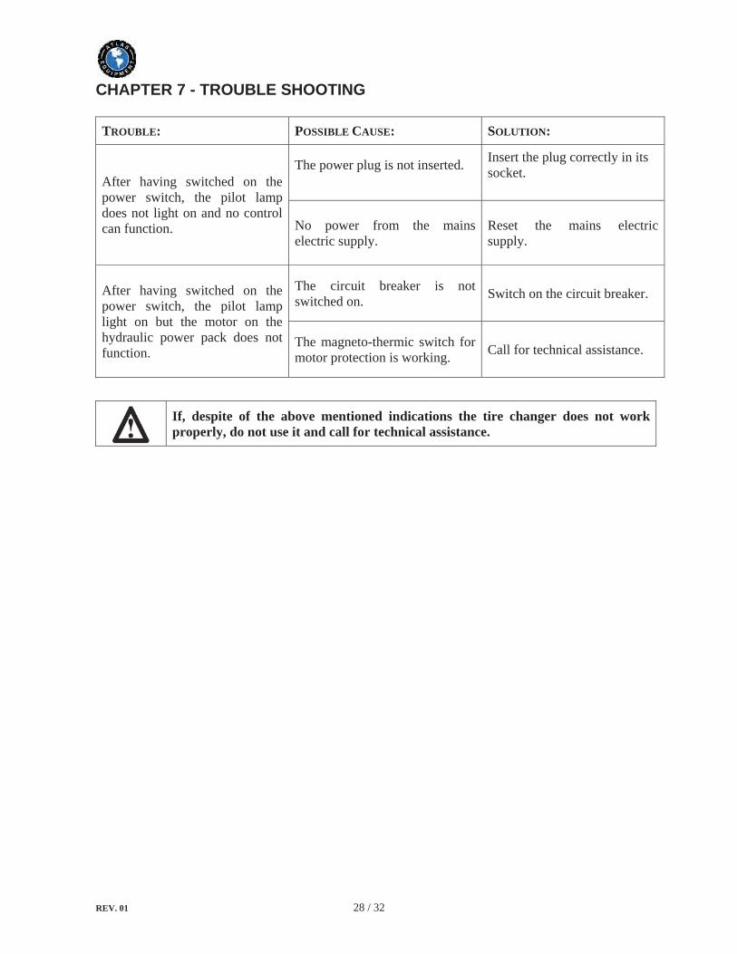
TROUBLE: POSSIBLE CAUSE: SOLUTION:
After having switched on the power switch, the pilot lamp does not light on and no control can function.
The power plug is not inserted. Insert the plug correctly in its socket.
No power from the mains electric supply.
Reset the mains electric supply.
After having switched on the power switch, the pilot lamp light on but the motor on the hydraulic power pack does not function.
The circuit breaker is not switched on. Switch on the circuit breaker.
The magneto-thermic switch for motor protection is working. Call for technical assistance.
If, despite of the above mentioned indications the tire changer does not work properly, do not use it and call for technical assistance.

REV. 01 29 / 32
CHAPTER 8 – MOVING, STORING AND SCRAPPING
8.1 MOVING THE MACHINE
The tire changer has got the lifting bracket (1, Fig. A) which has been positioned there on purpose for moving the machine. To move the machines, follow these instructions: 1) Low the chuck holding arm (2, Fig. A) completely down. 2) Close completely the jaws of the chuck (3, Fig. A). 3) Bring the sliding table (4, Fig. A) at the end of its travel, near the arm. 4) Insert into the lifting bracket a hoisting belt (at least 60 mm wide and of a length sufficient to bring the hook of the belt above the tire changer). 5) With the special belt ring bring the 2 ends of the belt together and lift the machine with a sufficiently strong lifting truck.
8.2 STORING
If the machine as to be stored for a long time (3-4 months) you have to: 1) Close the jaws of the chuck; low the chuck holding arm down; low the tool holding arm down in working position. 2) Disconnect the machine from all power sources. 3) Grease all the parts that could be damaged if they dry out:
the chuck the slot of the tool holding arm the slides of the carriage the tool
4) Empty oil/hydraulic fluid reservoirs and wrap the machine in a sheet of protective plastic to prevent dust from reaching the internal working parts. If the machine as to working again after a long storing period, it is necessary to:
fill the oil into the reservoirs again.
8.3 SCRAPPING A MACHINE
When your machine’s working life is over and it can no longer be used, it must be made inoperative by removing any connection to power sources. These units are considered as special waste material, and should be broken down into uniform parts and disposed of in compliance with current laws and regulations. If the packing are not polluting or non-biodegradable, deliver them to appropriate handling station.
If this machine catches fire, use dust or CO2.

REV. 01 30 / 32
CHAPTER 9 – OPTIONAL ACCESSORIES
The following optional accessories are available for the tire changer:
137/90 Set of 4 jaws for alloy rims Mounted on the jaws of the chuck, they are used to operate on alloy rims without damaging them.
138/90 Pliers for alloy rims It is used to work with alloy rims without damaging them.
140/90 Clamp extension For rims exceeding a diameter of 46" and without a flange with a central hole.
148/90 Ring lifter For the wheels with rings, it is used to facilitate to split and lift the rings from the rim
REV. 01 31 / 32
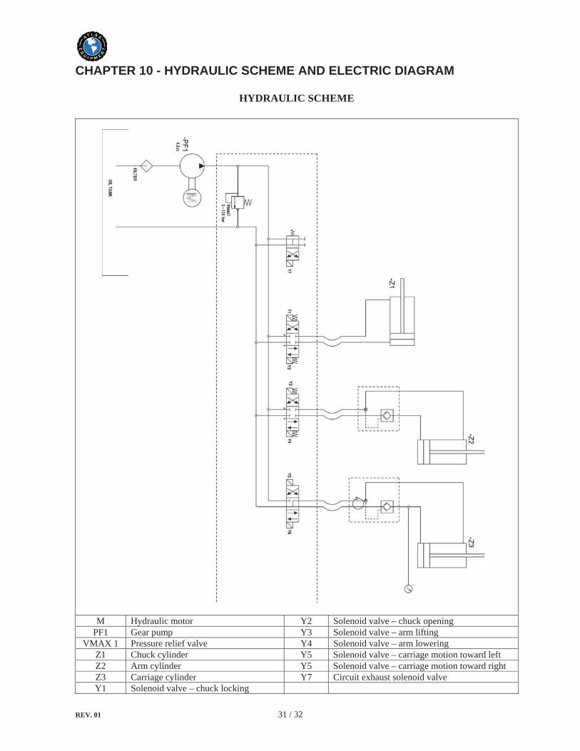
CHAPTER 10 - HYDRAULIC SCHEME AND ELECTRIC DIAGRAM
HYDRAULIC SCHEME
M Hydraulic motor Y2 Solenoid valve – chuck opening PF1 Gear pump Y3 Solenoid valve – arm lifting
VMAX 1 Pressure relief valve Y4 Solenoid valve – arm lowering Z1 Chuck cylinder Y5 Solenoid valve – carriage motion toward left Z2 Arm cylinder Y5 Solenoid valve – carriage motion toward right Z3 Carriage cylinder Y7 Circuit exhaust solenoid valve Y1 Solenoid valve – chuck locking

REV. 01 32 / 32
ELECTRIC DIAGRAM
220V – 3PH
HK1 Power switch SB2 Manipulator HK2 Pole change switch SB3-1 Clockwise direction pedal switch M1 Chuck motor SB3-2 anticlockwise direction pedal switch M2 Hydraulic unit motor D1-D6 LED
1KM Contactor AC – clockwise direction YV1 Solenoid valve – chuck locking 2KM Contactor AC – anticlockwise direction YV2 Solenoid valve – chuck opening HL Pilot lamp YV3 Solenoid valve – arm lifting DZ Circuit breaker YV4 Solenoid valve – arm lowering V Rectifier YV5 Solenoid valve – carriage motion toward left T Transformer YV6 Solenoid valve – carriage motion toward right
SB1 Commutator (chuck switch) YV7 Circuit exhaust solenoid valve

WarrantyThis item has a one (1) year LIMITED warranty.
Atlas® Automotive Equipment warrants the equipment to the original purchaser against defects in material or workmanship under normal use for a period of one year from the date of purchase. This warranty shall be limited to the replacement of materials or parts found defective, at the discretion of Atlas®
Automotive Equipment and/or its authorized distributors. This limited one (1) year warranty DOES NOT apply to normal wear items (turntable jaws, belts, gauges, plastic jaw protectors, etc.). The limited one (1) year warranty does not include a labor warranty. Warranties do not apply to items that have been abused or misused.
Returned goods must be authorized to be returned (in writing) by Atlas® Automotive Equipment and/or an authorized distributor and must be prepaid to a designated location. All returns may be subject to a 15% handling and restocking charge. Returned goods must be in like-new condition complete with warranty and original shipping papers.
Customer’s Responsibilities
• Shall ensure that all air operated components are properly maintained• Shall ensure components are powered by well lubricated and moisture free compressed air
(if a suspected defective part has not been properly lubricated it will not be covered under warranty)
• Shall establish procedures to periodically maintain and inspect the equipment• Shall ensure that your wheel balancer is protected by a surge protector• Shall ensure that all equipment shall have adequate amperage service
THIS WARRANTY IS EXCLUSIVE AND IS LIEU OF ALL OTHER WARRANTIES EXPRESSED OR IMPLIED INCLUDING ANY IMPLIED WARRANTY OR MERCHANTABILITY OR ANY IMPLIED WARRANTY OF FITNESS FROM A PARTICULAR PURPOSE, AND ALL SUCH IMPLIED WARRANTIES ARE EXPRESSLY EXCLUDED.
THE REMEDIES DESCRIBED ARE EXCLUSIVE AND IN NO EVENT SHALL THE MANUFACTURER, NOR ANY SALES AGENT OR OTHER COMPANY AFFILIATED WITH IT OR THEM, BE LIABLE FOR SPECIAL CONSEQUENTIAL OR INCIDENTAL DAMAGES FOR THE BREACH OF OR DELAY IN PERFORMANCE OF THIS WARRANTY. THIS INCLUDES, BUT IS NOT LIMITED TO, LOSS OF PROFIT, RENTAL OR SUBSTITUTE EQUIPMENT OR OTHER COMMERCIAL LOSS.
For warranty assistance, please call 866-898-2604. Please have your invoice number ready so that we may be able to serve you better. Warranty procedures cannot be initiated without an invoice number corresponding to the product serial number.
For further product and distributor information, please visit www.atlasautoequipment.com