principles of software engineeringebooks.lpude.in/computer_application/bsc_it/term_5/... ·...
TRANSCRIPT

Principles of Software EngineeringDCAP305

PRINCIPLES OF SOFTWAREENGINEERING

Copyright © 2013, Sajal DebnathAll rights reserved
Produced & Printed byEXCEL BOOKS PRIVATE LIMITED
A-45, Naraina, Phase-I,New Delhi-110028
forLovely Professional University
Phagwara
CONTENTS
Unit 1: Introduction to Software Engineering 1
Unit 2: Software Processes and Models 19
Unit 3: Software Requirements 35
Unit 4: Introduction to Validation, Metrics and Software Architecture 55
Unit 5: Software Project Planning 81
Unit 6: Functional Design 109
Unit 7: Introduction to Verification 132
Unit 8: Detailed Design 141
Unit 9: Metrics 150
Unit 10: Coding 164
Unit 11: Coding Process 181
Unit 12: Refactoring 188
Unit 13: Software Testing-I 201
Unit 14: Software Testing-II 218
SYLLABUS
Principles of Software Engineering
Objectives:
To enable the student to understand software development process.
To enable the student to learn various software engineering approaches.
To enable the student to implement various software testing techniques.
To enable the student to prepare software requirement specification documents.
To enable the student to learn various verification and validation techniques.
To enable the Student to practice software engineering concepts using UML.
Sr. No. Description
1. Introduction: Concept of Software Engineering. Software Engineering Challenges & Approach.
2. Software Processes and Models: Processes and Models, Characteristics of Software Model, Waterfall, Prototype, Iterative, Time Boxing. Comparison.
3. Software Requirements: Problem Analysis, DataFlow, Object Oriented Modelling, Prototyping. Software Requirement Specification Document: SRS, Characteristics, Components, Specification Language, Structure of Document.
4. Introduction to Validation, Metrics: Function Point & Quality Metrics. Software Architecture: Architecture Views, Architecture Styles: Client/Server, Shared Data.
5. Software Project Planning: Process Planning, Effort Estimation, COCOMO Model, Project Scheduling and Staffing. Intro to Software Configuration Management: Quality Plan, Risk Management, Project Monitoring.
6. Functional Design: Principles, Abstraction, Modularity, Top Down, Bottom Up Approach. Coupling, Cohesion. Structure Charts, Data Flow Diagrams, Design Heuristics.
7. Intro to Verification: Meaning, Metrics: Network, Stability, Information Flow.
8. Detailed Design: Process Design Language. Logic/Algorithm Design. Verification of Logic/Algorithm Design. Metrics: Cyclomatic Complexity, Data Bindings, Cohesion Metric.
9. Coding: Common Errors, Structured Programming, Programming Practices, Coding standards. Coding Process: Incremental, Test Driven, Pair Programming. Refactoring: Meaning and Example. Verification, Metrics: Size & Complexity.
10. Testing: Fundamentals, Error, Fault, Failure, Test Oracles, Test Cases & Criteria. Black Box: Equivalence Class Partitioning, Boundary Value Analysis. White Box: Control Flow Based, Data Flow Based Testing Process: Levels of Testing, Test Plan, Test Case Specifications, Execution and Analysis. Logging and Tracking. Metrics: Failure Data and Parameter Estimation.

LOVELY PROFESSIONAL UNIVERSITY 1
Unit 1: Introduction to Software Engineering
NotesUnit 1: Introduction to Software Engineering
CONTENTS
Objectives
Introduction
1.1 Concepts of Software Engineering
1.1.1 Evolving Role of Software
1.1.2 Software Characteristics
1.1.3 Program vs. Software
1.1.4 Software Engineering and its Relationship with other Disciplines
1.1.5 Software Myths
1.1.6 Software: A Crisis on the Horizon
1.1.7 Software Engineering Framework
1.1.8 Difference between Software Engineering and Computer Science
1.1.9 Difference between Software Engineering and System Engineering
1.2 Software Engineering Challenges and Approach
1.3 Summary
1.4 Keywords
1.5 Review Questions
1.6 Further Readings
Objectives
After studying this unit, you will be able to:
� Discuss various concepts of software engineering.
� Discuss software myths
� Describe software engineering framework.
� Explain the software engineering challenges and approach
Introduction
The complexity and nature of software have changed tremendously in the last four decades. Inthe 70s applications ran on a single processor, received single line inputs and producedalphanumeric results. However, the applications today are far more complex running on client-server technology and have a user friendly GUI. They run on multiple processors with differentOS and even on different geographical machines. The software groups work hard as they can tokeep abreast of the rapidly changing new technologies and cope with the developmental issuesand backlogs. Even the Software Engineering Institute (SEI) advises to improve upon thedevelopmental process. The “change” is an inevitable need of the hour. However, it often leadsto conflicts between the groups of people who embrace change and those who strictly stick to

2 LOVELY PROFESSIONAL UNIVERSITY
Principles of Software Engineering
Notes the traditional ways of working. Thus, there is an urgent need to adopt software engineeringconcepts, practices, strategies to avoid conflicts and in order to improve the software developmentto deliver good quality software within budget and time.
1.1 Concepts of Software Engineering
The concepts of software engineering are discussed below:
1.1.1 Evolving Role of Software
The role of software has undergone drastic change in the last few decades. These improvementsrange through hardware, computing architecture, memory, storage capacity and a wide rangeof unusual input and output conditions. All these significant improvements have lead to thedevelopment of more complex and sophisticated computer-based systems. Sophistication leadsto better results but can cause problems for those who build these systems.
Lone programmer has been replaced by a team of software experts. These experts focus onindividual parts of technology in order to deliver a complex application. However, the expertsstill face the same questions as that by a lone programmer:
� Why does it take long to finish software?
� Why are the costs of development so high?
� Why aren’t all the errors discovered before delivering the software to customers?
� Why is it difficult to measure the progress of developing software?
All these questions and many more have lead to the manifestation of the concern about softwareand the manner in which it is developed – a concern which lead to the evolution of the softwareengineering practices.
Today, software takes on a dual role. It is a product and, at the same time, the vehicle fordelivering a product. As a product, it delivers the computing potential embodied by computerhardware or, more broadly, a network of computers that are accessible by local hardware.Whether it resides within a cellular phone or operates inside a mainframe computer, software isan information transformer-producing, managing, acquiring, modifying, displaying, ortransmitting information that can be as simple as a single bit or as complex as a multimediapresentation. As the vehicle used to deliver the product, software acts as the basis for the controlof the computer (operating systems), the communication of information (networks), and thecreation and control of other programs (software tools and environments). Software deliversthe most important product of our time-information.
Software transforms personal data (e.g., an individual’s financial transactions) so that the datacan be more useful in a local context; it manages business information to enhance competitiveness;it provides a gateway to worldwide information networks (e.g., Internet) and provides themeans for acquiring information in all of its forms.
The role of computer software has undergone significant change over a time span of little morethan 50 years. Dramatic improvements in hardware performance, profound changes in computingarchitectures, vast increases in memory and storage capacity, and a wide variety of exotic inputand output options have all precipitated more sophisticated and complex computer-basedsystems.
The lone programmer of an earlier era has been replaced by a team of software specialists, eachfocusing on one part of the technology required to deliver a complex application.
LOVELY PROFESSIONAL UNIVERSITY 3
Unit 1: Introduction to Software Engineering
NotesThe same questions asked of the lone programmer are being asked when modern computer-based systems are built. Give answers to questions:
1. Why does it take so long to get software finished?
2. Why are development costs so high?
3. Why can’t we find all the errors before we give the software to customers?
4. Why do we continue to have difficulty in measuring progress as software is beingdeveloped?
1.1.2 Software Characteristics
In the first NATO conference on software engineering in 1968, Fritz Bauer defined Softwareengineering as “The establishment and use of sound engineering principles in order to obtaineconomically software that is reliable and works efficiently on real machines”. Stephen Schachdefined the same as “A discipline whose aim is the production of quality software, software thatis delivered on time, within budget and that satisfies its requirements”.
Did u know? The software differs from hardware as it is more logical in nature and hence,the difference in characteristics.
Let us now explore the characteristics of software in detail:
� Software is Developed or Engineered and not Manufactured: Although there exists fewsimilarities between the hardware manufacturing and software development, the twoactivities differ fundamentally. Both require a good design to attain high quality. But themanufacturing phase of hardware can induce quality related problems that are either non-existent for software or can be easily rectified. Although both activities depend on peoplebut the relationship between people and work is totally different.
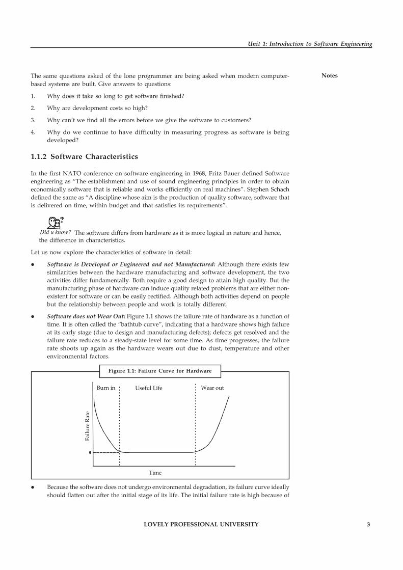
� Software does not Wear Out: Figure 1.1 shows the failure rate of hardware as a function oftime. It is often called the “bathtub curve”, indicating that a hardware shows high failureat its early stage (due to design and manufacturing defects); defects get resolved and thefailure rate reduces to a steady-state level for some time. As time progresses, the failurerate shoots up again as the hardware wears out due to dust, temperature and otherenvironmental factors.
�
Failu
re R
ate
Burn in Useful Life Wear out
Time
� Because the software does not undergo environmental degradation, its failure curve ideallyshould flatten out after the initial stage of its life. The initial failure rate is high because of
Figure 1.1: Failure Curve for Hardware

4 LOVELY PROFESSIONAL UNIVERSITY
Principles of Software Engineering
Notes undiscovered defects. Once these defects are fixed, the curve flattens at a later stage. Thus,the software does not wear out but deteriorates.
� The actual curve as shown in Figure 1.2 can explain the contradiction stated above. Becausesoftware undergoes changes during its lifetime as a part of the maintenance activities,new defects creep in causing the failure rate to rise (spike). While the software enters itssteady state further more changes are added which induce further more defects and hence,spikes in the failure rate.
Time
Upg
rad
e
Upg
rad
e
Upg
rad
e
Failu
re R
ate
�
Test/Debug Useful Life Obsolescence
The minimum failure rate rises and the software deteriorates due to induction of frequentchanges.
� Software is Custom Built and Not Designed Component Wise: Software is designed andbuilt so that it can be reused in different programs. Few decades ago subroutine librarieswere created that re-used well defined algorithms but had a limited domain. Today thisview has been extended to ensure re-usability of not only algorithms but data structuresas well.
Notes The data and the processes that operate on this data were combined together to beable to use later on.
1.1.3 Program vs. Software
Software is more than programs. It comprises of programs, documentation to use these programsand the procedures that operate on the software systems.
Programs Documentation
Operating procedures
Figure 1.2: Failure Curve for Software
Figure 1.3: Components of Software
LOVELY PROFESSIONAL UNIVERSITY 5
Unit 1: Introduction to Software Engineering
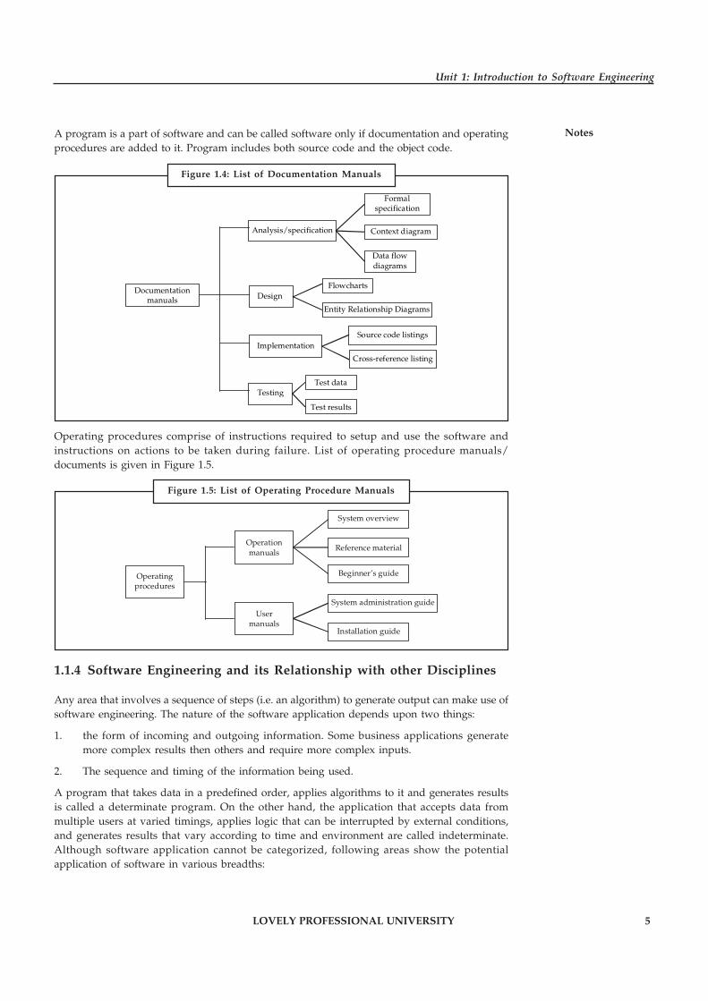
NotesA program is a part of software and can be called software only if documentation and operatingprocedures are added to it. Program includes both source code and the object code.
Analysis/specification
Design
Implementation
Testing
Documentation manuals
Formal specification
Context diagram
Data flow diagrams
Flowcharts
Entity Relationship Diagrams
Source code listings
Cross-reference listing
Test data
Test results
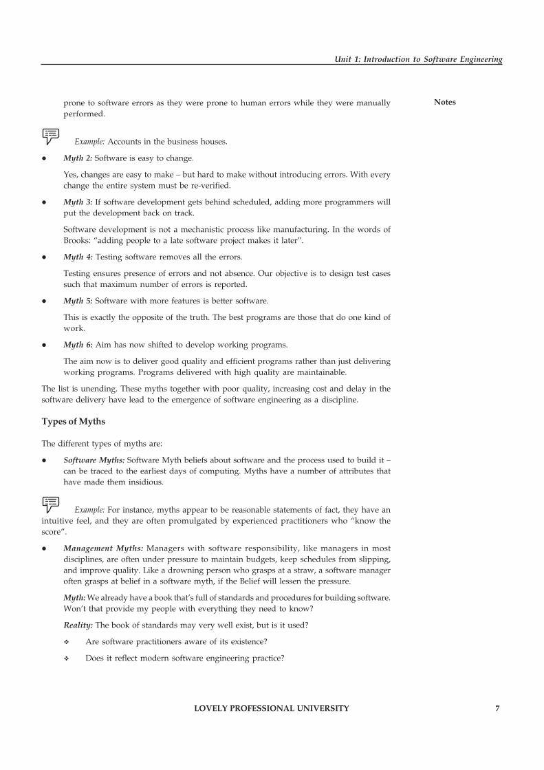
Operating procedures comprise of instructions required to setup and use the software andinstructions on actions to be taken during failure. List of operating procedure manuals/documents is given in Figure 1.5.
Operating procedures
Operation manuals
User manuals
System overview
Reference material
Beginner’s guide
System administration guide
Installation guide
1.1.4 Software Engineering and its Relationship with other Disciplines
Any area that involves a sequence of steps (i.e. an algorithm) to generate output can make use ofsoftware engineering. The nature of the software application depends upon two things:
1. the form of incoming and outgoing information. Some business applications generatemore complex results then others and require more complex inputs.
2. The sequence and timing of the information being used.
A program that takes data in a predefined order, applies algorithms to it and generates resultsis called a determinate program. On the other hand, the application that accepts data frommultiple users at varied timings, applies logic that can be interrupted by external conditions,and generates results that vary according to time and environment are called indeterminate.Although software application cannot be categorized, following areas show the potentialapplication of software in various breadths:
Figure 1.4: List of Documentation Manuals
Figure 1.5: List of Operating Procedure Manuals

6 LOVELY PROFESSIONAL UNIVERSITY
Principles of Software Engineering
Notes � Real-time Software: It refers to the software that controls the events and when they occur.The data gatherer component of the software gathers the data and formats it into anacceptable form. The analyzer component that transforms information as required by theapplication. The output component that interacts with the external environment and themonitoring component that coordinates with all the components to generate timely results.
� Business Software: It is the single largest area of software application. These areas use oneor more large databases for business information and reframe the information in such amanner that facilitates business operations and decision making.
Example: Library management, data inventory, HR management, etc.
� System Software: It is the software program that interacts with the hardware componentsso that other application software can run on it.
Example: Operating systems like Windows, Unix, DOS, etc., are examples of the systemsoftware.
Such type of software perform a wide range of operations like allocation and distributionof memory amongst various computer processes, process scheduling, resource scheduling,etc.
� Embedded Software: This software resides in the commodities for the consumer and industrymarkets in the form of read-only memory devices. They perform limited functions e.g.keypad of an automatic washing machine or significant functions as per requirement e.g.dashboard functions in an aircraft.
� Personal Computer Software: These software programs have grown rapidly over the pastfew decades. These include the like of database management, entertainment, computergraphics, multimedia, etc.
� Web-based Software: The web-pages displayed by a browser are programs that includeexecutable instructions (e.g. CGI, Perl, Java), hypertext and audio-visual formats.
� Artificial Intelligence Software: AI software uses algorithms to solve problems that arenot open to simple computing and analysis.
Example: Pattern matching (voice or image), game playing, robotics, expert systems,etc.
� Engineering Software: The software is characterized by number-crunching algorithmsranging from molecular biology, automated manufacturing to space shuttle orbitmanagement, etc.
Task Make distinction between system software and embedded software.
1.1.5 Software Myths
� Myth 1: Computers are more reliable than the devices they have replaced.
Considering the reusability of the software, it can undoubtedly be said that the softwaredoes not fail. However, certain areas which have been mechanized have now become
LOVELY PROFESSIONAL UNIVERSITY 7
Unit 1: Introduction to Software Engineering
Notesprone to software errors as they were prone to human errors while they were manuallyperformed.
Example: Accounts in the business houses.
� Myth 2: Software is easy to change.
Yes, changes are easy to make – but hard to make without introducing errors. With everychange the entire system must be re-verified.
� Myth 3: If software development gets behind scheduled, adding more programmers willput the development back on track.
Software development is not a mechanistic process like manufacturing. In the words ofBrooks: “adding people to a late software project makes it later”.
� Myth 4: Testing software removes all the errors.
Testing ensures presence of errors and not absence. Our objective is to design test casessuch that maximum number of errors is reported.
� Myth 5: Software with more features is better software.
This is exactly the opposite of the truth. The best programs are those that do one kind ofwork.
� Myth 6: Aim has now shifted to develop working programs.
The aim now is to deliver good quality and efficient programs rather than just deliveringworking programs. Programs delivered with high quality are maintainable.
The list is unending. These myths together with poor quality, increasing cost and delay in thesoftware delivery have lead to the emergence of software engineering as a discipline.
Types of Myths
The different types of myths are:
� Software Myths: Software Myth beliefs about software and the process used to build it –can be traced to the earliest days of computing. Myths have a number of attributes thathave made them insidious.
Example: For instance, myths appear to be reasonable statements of fact, they have anintuitive feel, and they are often promulgated by experienced practitioners who “know thescore”.
� Management Myths: Managers with software responsibility, like managers in mostdisciplines, are often under pressure to maintain budgets, keep schedules from slipping,and improve quality. Like a drowning person who grasps at a straw, a software manageroften grasps at belief in a software myth, if the Belief will lessen the pressure.
Myth: We already have a book that’s full of standards and procedures for building software.Won’t that provide my people with everything they need to know?
Reality: The book of standards may very well exist, but is it used?
� Are software practitioners aware of its existence?
� Does it reflect modern software engineering practice?
8 LOVELY PROFESSIONAL UNIVERSITY
Principles of Software Engineering
Notes � Is it complete? Is it adaptable?
� Is it streamlined to improve time to delivery while still maintaining a focus onQuality?
In many cases, the answer to these entire questions is no:
� Myth: If we get behind schedule, we can add more programmers and catch up(sometimes called the Mongolian horde concept).
� Reality: Software development is not a mechanistic process like manufacturing. Inthe words of Brooks: “Adding people to a late software project makes it later.” Atfirst, this statement may seem counter-intuitive. However, as new people are added,people who were working must spend time educating the newcomers, therebyreducing the amount of time spent on productive development effort.
� Myth: If we decide to outsource the software project to a third party, I can just relaxand let that firm build it.
� Reality: If an organization does not understand how to manage and control softwareproject internally, it will invariably struggle when it out sources software project.
� Customer Myths: A customer who requests computer software may be a person at the nextdesk, a technical group down the hall, the marketing/sales department, or an outsidecompany that has requested software under contract. In many cases, the customer believesmyths about software because software managers and practitioners do little to correctmisinformation.
!Caution Myths led to false expectations and ultimately, dissatisfaction with the developers.
� Myth: A general statement of objectives is sufficient to begin writing programs wecan fill in details later.
� Reality: Although a comprehensive and stable statement of requirements is not alwayspossible, an ambiguous statement of objectives is a recipe for disaster. Unambiguousrequirements are developed only through effective and continuous communicationbetween customer and developer.
� Myth: Project requirements continually change, but change can be easilyaccommodated because software is flexible.
� Reality: It’s true that software requirement change, but the impact of change varieswith the time at which it is introduced. When requirement changes are requestedearly, cost impact is relatively small.
However, as time passes, cost impact grows rapidly – resources have been committed, a designframework has been established, and change can cause upheaval that requires additional resourcesand major design modification.
1.1.6 Software: A Crisis on the Horizon
It has been expected that, by 1990, the one half of work force will depend on computers andsoftware to do its daily work. As computer hardware costs persist to decline, the demand fornew applications software continues to boost at a rapid rate. The existing stock of softwarecontinues to grow, and the effort required for maintaining the stock continues to increase aswell. At the same time, there is a major shortage of qualified software professionals. Combiningthese factors, one might project that at some point of time, every worker will have to be concerned
LOVELY PROFESSIONAL UNIVERSITY 9
Unit 1: Introduction to Software Engineering
Notesfor software development and maintenance. For now, the software development scene is oftencharacterised by:
� Size: Software is becoming larger and more complex with the growing complexity andexpectations out of software.
Example: The code in consumer products is doubling every couple of years.
� Quality: Many software products have poor quality i.e., the software produces defectsafter put into use due to ineffective testing techniques.
Example: Software testing typically finds 25 defects per 1000 lines of code.
� Cost: Software development is costly i.e., in terms of time taken to develop and the moneyinvolved.
Example: Development of the FAA’s Advance Automation System cost over $700 perline of code.
� Delayed Delivery: Serious schedule overruns are common. Very often the software takeslonger than the estimated time to develop which in turn leads to cost shooting up.
Example: One in four large-scale development projects is never completed.
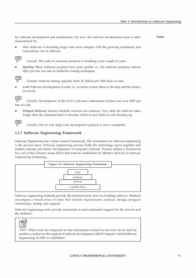
1.1.7 Software Engineering Framework
Software Engineering has a three layered framework. The foundation for software engineeringis the process layer. Software engineering process holds the technology layers together andenables rational and timely development of computer software. Process defines a frameworkfor a set of Key Process Areas (KPA) that must be established for effective delivery of softwareengineering technology.
a quality focus
process
methods
tools
Software engineering methods provide the technical know how for building software. Methodsencompass a broad array of tasks that include requirements analysis, design, programconstruction, testing, and support.
Software engineering tools provide automated or semi-automated support for the process andthe methods.
Notes When tools are integrated so that information created by one tool can be used byanother, a system for the support of software development called Computer Aided SoftwareEngineering (CASE) is established.
Figure 1.6: Software Engineering Framework
10 LOVELY PROFESSIONAL UNIVERSITY
Principles of Software Engineering
Notes Software Process
A process is a series of steps involving activities, constraints and resources that produce anintended output of some kind.
In simpler words, when you build a product or system, it’s important to go through a series ofpredictable steps – a road map that helps you create a timely, high quality result. The road mapthat you follow is called a software process.
In the last decade there has been a great deal of resources devoted to the definition,implementation, and improvement of software development processes.
� ISO 9000
� Software Process Improvement and Capability Determination (SPICE)
� SEI Processes
� Capability Maturity Model (CMM) for software
� Personal Software Process (PSP)
� Team Software Process (TSP)
� A set of activities whose goal is the development or evolution of software.
Generic activities in all software processes are:
� Specification: what the system should do and its development constraints
� Development: production of the software system
� Validation: checking that the software is what the customer wants
� Evolution: changing the software in response to changing demands.
Software Process Model
� A simplified representation of a software process, presented from a specific perspective.
Example: Process perspectives are:
� Workflow perspective – sequence of activities
� Data-flow perspective – information flow
� Role/action perspective – who does what
Generic Process Models
� Waterfall
� Evolutionary development
� Formal transformation
� Integration from reusable components.
Software Engineering Methods
� Structured approaches to software development which include system models, notations,rules, design advice and process guidance
� Model descriptions – Descriptions of graphical models, which should be produced
LOVELY PROFESSIONAL UNIVERSITY 11
Unit 1: Introduction to Software Engineering
Notes� Rules Constraints applied to system models
� Recommendations – Advice on good design practice
� Process guidance – What activities to follow
CASE (Computer-Aided Software Engineering)
Software systems which are intended to provide automated support for software process activities.CASE systems are often used for method support:
� Upper-CASE: Tools to support the early process activities of requirements and design.
� Lower-CASE: Tools to support later activities such as programming, debugging and testing.
Attributes of Good Software
The software should deliver the required functionality and performance to the user and shouldbe maintainable, dependable and usable.
� Maintainability: Software must evolve to meet changing needs.
� Dependability: Software must be trustworthy.
� Efficiency: Software should not make wasteful use of system resources.
� Usability: Software must be usable by the users for which it was designed.
Task Software engineering methods only became widely used when CASE technologybecame available to support them. Suggest five types of method support, which can beprovided by CASE tools.
1.1.8 Difference between Software Engineering and Computer Science
Computer science covers the core concepts and technologies involved with how to make acomputer do something while software engineering focuses on how to design and build software.The difference seems minimal but there is a major difference in the sense that in SoftwareEngineering you will learn how to analyze, design, build and maintain software in teams. Youwill learn about working with people (communication, management, and working with non-technical customers), processes for developing software, and how to measure and analyze thesoftware product and the software process.
Computer science is concerned with theory and fundamentals; software engineering is concernedwith the practicalities of developing and delivering useful software.
Did u know? Computer science theories are currently insufficient to act as a completeunderpinning for software engineering.
1.1.9 Difference between Software Engineering and System Engineering
As mentioned before software engineering deals with building and maintaining softwaresystems. System engineering is an interdisciplinary field of engineering that focuses on thedevelopment and organization of complex artificial systems. System engineering integrates
12 LOVELY PROFESSIONAL UNIVERSITY
Principles of Software Engineering
Notes other disciplines and specialty groups into a team effort, forming a structured developmentprocess that proceeds from concept to production to operation and disposable.
System Engineering considers both the business and technical needs of all customers, with thegoal of providing a quality product that meets the user needs.
Self Assessment
Fill in the blanks:
1. A …………………… is a part of software and can be called software only if documentationand operating procedures are added to it.
2. A program that takes data in a predefined order, applies algorithms to it and generatesresults is called a …………………… program.
3. …………………… software refers to the software that controls the events and when theyoccur.
4. …………………… is the software program that interacts with the hardware componentsso that other application software can run on it.
5. …………………… software resides in the commodities for the consumer and industrymarkets in the form of read-only memory devices.
6. …………………… software uses algorithms to solve problems that are not open to simplecomputing and analysis.
7. …………………… software programs have grown rapidly over the past few decades.
8. Program includes both source code and the …………………… code.
9. …………………… beliefs about software and the process used to build it – can be traced tothe earliest days of computing.
10. …………………… tools support the early process activities of requirements and design.
11. The foundation for software engineering is the …………………… layer.
1.2 Software Engineering Challenges and Approach
Over the years, the term software engineering has been attributed with a number of definitions.A common one that is used to characterize the discipline is a methodical, engineering approachto the design and development of software production, throughout its whole life cycle. It canalso be considered analogous to an encompassing viewpoint which combines a number ofpotential sub-disciplines, including system analysis, system development and accompanyingdocumentation as well as testing, amongst others.
The software engineering discipline has been faced with a number of challenges over the years,including those related to quality, management and under estimation. Although numerousapproaches, including methods and frameworks have been introduced and adopted as industrystandards and/or best practices that have mitigated many of these issues, the discipline is stillfaced with a number of challenges, and future challenges are also bound to appear.
Sommerville mentions three fundamental categories of such challenges, namely:
� Legacy Systems: Old, valuable systems must be maintained and updated
� Heterogeneity: Systems are distributed and include a mix of hardware and software

LOVELY PROFESSIONAL UNIVERSITY 13
Unit 1: Introduction to Software Engineering
Notes� Delivery: There is increasing pressure for faster delivery of software
� Trust: The ability to demonstrate to the end user the trustworthiness of the software
Although these are undoubtedly critical, perhaps one can also consider a number of others. Costestimation and containment is potentially one of these issues and one which continues to berelatively difficult to control, and will potentially continue to be so in the near future, eventhough costing models such as COCOMO in its latest incarnation has become a versatile costestimation method and used widely in the industry. Software costs tend to be an order ofmagnitude the cost the hardware they are executed on. This indicates that potentially bettersoftware development tools which potentially provide higher levels of abstractions are required,and which will hopefully lead to faster development times without reducing overall quality.Greater emphasis, with all its repercussions, on automated code generation will probably becomemore prevalent in the future in this respect.
Although metrics exist with respect to certain aspects for measuring the quality of software, inthe future the emphasis on this will increase. This will put greater importance on software re-usability in general.
As more and more software seems to be shifting towards the adoption of a configuration basedapproach where the base product(s) offer a generalized view of the product capabilities andallow the end user to be able to provide specific business rules to enable tackling aspects ofbusiness in a particular fashion via configuration, or rather as it is usually referred to asconstruction-by-configuration, it becomes fundamental that the software engineering disciplinealso gears up to this new approach of delivering solutions as until recently, this aspect has beenprimarily neglected as identified in.
Another challenge for the software engineering discipline is the increasing concern with respectto the design and management of software projects whose complexity is increasing exponentially.This is amplified, as hinted earlier, with the greater level of inter-connectedness, with theaccompanying dependencies imposed by most modern software, which will in turn place furtheremphasis on abstraction. This is an area where, potentially, agent-based intelligent adaptivesystems become a more natural choice to minimize the increasing complexity of softwaresystems in general.
Legacy systems will also continue to present a considerable challenge to software engineeringbecause the need to ensure that the old technologies are capable to co-exist with the new andvice-versa will be much greater in the near future. This issue arises from the fact that while byand large it is an accepted fact that application and system topologies change very rapidly,throughout the metamorphosis cycles of predominant technologies, software systems evolveinto mission critical tools for organizations. The repetitive enhancement and modification cyclesperformed on these systems inhibit the proper evolution process of such information systems,which almost inevitably leads to demotion of these systems to legacy status and outside themainstream technology sphere.
!Caution It is impossible to re-engineer these system with every technology cycle primarilydue to cost.
From a human resources perspective, although the death of traditional application programmerrole has been touted on a number of occasions, the current market still seems to require morethan actually available, which is a big contradiction. However, as highlighted in, changingforces and development patterns, including the greater acceptance of off-the-shelf packages willprobably have its affect on software engineering in general, especially if there is a shift towardsa more declarative type of approach to programming, again as hinted in.
14 LOVELY PROFESSIONAL UNIVERSITY
Principles of Software Engineering
Notes Although great strides have been and are continuously being made to bring software engineeringto the same level of traditional engineering disciplines, admittedly, to date, there are still areaswhich are not yet up to scratch, perhaps stemming out primarily (not solely) from the fact thatsome artistic creativeness/flair is considered by many as a requirement in certain specific areasof software engineering. Greater consensus on best practices and patterns is required, especiallybetween academia and the industry. Initiatives such as CHASE (Challenges and Achievementsin Software Engineering) strive to “contrast an industrial perspective with an academic perspective,in order to identify the main achievements of the past, i.e., the state-of-the-art, and to identifythe main challenges for the future.” However, looking back at the improvements made by thediscipline during the last couple of years, one can reckon that solutions will be identifiedaccordingly, and as time goes by, the software engineering role will become more formal, withtools, approaches and models which resemble more closely the other, traditionally more formal,engineering disciplines.
Self Assessment
State whether the following statements are true or false:
12. There is increasing pressure for faster delivery of software.
13. Software costs tend to be an order of magnitude the cost the hardware they are executedon.
14. Although metrics exist with respect to certain aspects for measuring the quality of software,in the future the emphasis on this will decrease.
15. Process defines a framework for a set of Key Process Areas (KPA) that must be establishedfor effective delivery of software engineering technology.
�Case Study Client Server
Introduction
ACME Financial is a fast growing company that owes part of its growth to several recentacquisitions. ACME Financial now wants to consolidate the companies’ informationtechnology resources to eliminate redundancy and share information among the newcompanies. The Chief Information Officer (CIO) has oversight responsibility for the projectand has hired Client/Servers R Us to develop the architecture for the new corporateinformation system. Joe Consultant of C/S R Us presented 3 client/server designs to theCIO and is requesting the CIO to select one. The CIO is not sure which middleware designis best for the company’s goals. The CIO has asked Chris Consultant to present theadvantages and disadvantages for each of the alternatives.
Background
ACME Financial Incorporated (AF Inc.) is an investment banking company that providesan online service that allows their clients to access account and market information. ACMEFinancial Inc. recently acquired several small and medium sized companies throughoutthe country, each with their own financial and accounting systems. Almost all of thecompanies have developed their own application software for their analysts’ use in theirdaily jobs, but only a few provided online account service. The analytical tools rely onnear-real time market data and historical market data. The CIO wants to consolidate thefinancial and accounting information into a corporate information system that can support
Contd...

LOVELY PROFESSIONAL UNIVERSITY 15
Unit 1: Introduction to Software Engineering
Notesdecision support applications for corporate management. Naturally, since the computerhardware is different for different companies, the CIO expects to upgrade the hardware toaccommodate the new Information Technology (IT) system. The CIO will select the bestanalytical software as the standard software used by all company analysts. Each local sitewill be expected to provide an online service for their customers. Customers will be giventhe necessary application software to access their account information. Finally, ACMEFinancial has developed special data mining software that gives them a competitiveadvantage. AF Inc. offers their customers investment advice based on the informationderived by the data mining software. Each account manager receives the information andthen provides tailored recommendations to each customer based on their portfolio.
System Requirements
The following list of system requirements reflects the system’s relative priorities:
1. Availability: The CIO’s number one priority is high availability. AF Inc. marketstheir reliability and feels that most clients choose them for their dependability. TheCIO wants to maximize the system’s availability. To achieve high availability, if aregional office cannot provide support then a customer must always have access tothe online service through a different office.
2. Data Integrity: The requirement for data integrity varies within the system. Themost important data are customer’s transactions. It is essential that a customer’stransaction is never lost and the system must guarantee that each transaction iscompleted. In contrast, data lost from the high data rate inputs, such as Reuter’s andthe NYSE, are easily recovered in subsequent broadcasts so it is not critical if somedata are lost during a broadcast.
3. Performance: Financial markets are highly volatile; time sensitivity of data ismeasured in minutes. Millions can be lost if information is delayed getting to theanalysts. The system must be able to support information broadcast throughout thenetwork.
4. Security: The CIO is concerned about the security of the data mining software andthe information produced by the data mining software. The Chief Executive Officerthinks the data mining information software provides a competitive advantage forthe company. If an unauthorized user had access to the information they could stealthe data mining applications or steal the information produced by the data miningsoftware. In either case, the perpetrator could make the same investmentrecommendations as AF Inc. account managers. Therefore, if competitors had accessto the information the results could be financially devastating to the company. TheCIO is concerned that a competitor could pose as a customer and hack into thehighly sensitive information through his online service account.
5. Growth: The CIO envisions an incremental migration process to install the newsystem due to the magnitude of the change. Also, he expects that AF Inc. will continueto grow and acquire more companies. The CIO wants to be able to develop moreapplication software as new customer services are added. The CIO also wants to addmore near-real time information sources to the system.
6. Backup and Recovery: The CIO understands that the system will encounter problemsfrom time to time. A key factor in determining the system’s success is how quicklythe system can recover from a failure. Backup and recovery must be smooth andnon-disruptive. One way to ensure that the system can easily recover from a systemcrash is to make sure the data is duplicated elsewhere on the system. The corporatedatabase is the primary back up for each of the regional offices.
Contd...

16 LOVELY PROFESSIONAL UNIVERSITY
Principles of Software Engineering
Notes Each local office (Northeast, Northwest, Southeast, Southwest) has accesses a regionalinformation hub. Local offices use client software to access the local application server.These application servers access the local databases for almost all of the informationneeded on a daily basis. For access to information needed less frequently the applicationsoftware should access the central database at corporate headquarters. Each regionaldatabase has only the subset of information that is relevant for its area, whereas thecorporate headquarters maintains all of the information from each region as well as datathat is unique to corporate applications, such as additional accounting and companyfinancial information.
The corporate office is also responsible for the data mining software and information.Each of the regional databases is connected with high capacity links to the corporatedatabase. Finally, the corporate office receives information from Reuter’s, NYSE, NASDAQ,and other financial markets. The information flow fluctuates daily from 30 40 KBps to 4 5MBps. Twenty-five percent of the information is immediately broadcast to the regionaloffices to support the online account service. All the information is filtered and stored inthe database.
Architectural Alternatives
Alternative I: The Database Management System This alternative takes advantage of theextended functionality provided by the popular relational database managementcompanies, such as Oracle and Sybase. All information is delivered into the system whereit is immediately stored into one of the databases. The relational database managementsoftware is responsible for the distribution of information throughout the system. Clientscommunicate with the databases through Standard Query Language (SQL). Corporate andregional databases are kept synchronized using features supplied by the RDBMS software.Transactions are guaranteed by using special Transaction Processing Software. The vendor-supplied RDBMS software is responsible for back-up and recovery of all the databases.Data security is handled at the row level within each database. This means that clients canonly receive records for which their user has permission. Existing application softwaremay have to be modified to use SQL.
Alternative II: Common Object Request Broker Architecture (CORBA) This solutiondepends on CORBA to tie together the clients and databases. CORBA is responsible fordistributing data across the system. The RDBMS software is still responsible for the back-up and recovery, but the databases are kept synchronized using CORBA as the primarytransport mechanism for the data. Clients, application servers, and databases communicateto each other through CORBAs transport mechanism. Existing application software wouldbe wrapped in IDL to communicate with other applications. Special near-real time handlingapplication software would send the information to each of the regional offices where itwould be directed to clients that subscribe to the information.
Alternative III: Message and Queuing (M&Q) The message and queuing design usescommercial M & Q software combined with a transaction processing product to ensurecustomers transactions are completed. Dec Message Queue and MQ Series are some of theleading products for messaging and queuing software. Clients communicate to otherentities using messages. Messages are deposited in queues and the message and queuingmiddleware is responsible for message distribution to the appropriate clients. The softwareapplications will be modified to send and receive messages from queues.
Questions:
1. Describe in more detail the architecture of each alternative.
2. Evaluate each of the alternatives against the system requirements.
Source: http://www.cs.cmu.edu/afs/cs.cmu.edu/project/vit/ftp/pdf/client_server.pdf
LOVELY PROFESSIONAL UNIVERSITY 17
Unit 1: Introduction to Software Engineering
Notes1.3 Summary
� The software differs from hardware as it is more logical in nature and hence, the differencein characteristics.
� Software is more than programs. It comprises of programs, documentation to use theseprograms and the procedures that operate on the software systems.
� Any area that involves a sequence of steps (i.e. an algorithm) to generate output can makeuse of software engineering.
� The software myths together with poor quality, increasing cost and delay in the softwaredelivery have lead to the emergence of software engineering as a discipline.
� Software engineering process holds the technology layers together and enables rationaland timely development of computer software.
� The software engineering discipline has been faced with a number of challenges over theyears, including those related to quality, management and under estimation.
� One of the challenge for the software engineering discipline is the increasing concern withrespect to the design and management of software projects whose complexity is increasingexponentially.
� Legacy systems will also continue to present a considerable challenge to softwareengineering because the need to ensure that the old technologies are capable to co-existwith the new and vice-versa will be much greater in the near future
1.4 Keywords
Artificial Intelligence Software: AI software uses algorithms to solve problems that are notopen to simple computing and analysis.
Determinate Program: A program that takes data in a predefined order, applies algorithms to itand generates results is called a determinate program.
Process: A process is a series of steps involving activities, constraints and resources that producean intended output of some kind.
Program: A program is a part of software and can be called software only if documentation andoperating procedures are added to it.
Real-time Software: It refers to the software that controls the events and when they occur.
Software: It is defined as a discipline whose aim is the production of quality software, softwarethat is delivered on time, within budget and that satisfies its requirements.
System Engineering: System engineering is an interdisciplinary field of engineering that focuseson the development and organization of complex artificial systems.
System Software: It is the software program that interacts with the hardware components sothat other application software can run on it.
1.5 Review Questions
1. Process defines a framework for a set of Key Process Areas (KPA) that must be establishedfor effective delivery of software engineering technology. Analyze this statement.
2. “Software is designed and built so that it can be reused in different programs.” Substantiatewith suitable examples.

18 LOVELY PROFESSIONAL UNIVERSITY
Principles of Software Engineering
Notes 3. Suppose you are the software engineer of a modern and technically equipped companythen explain how software delivers the most important product of our time-information.
4. Explain the different types of myths in software engineering.
5. Critically analyze the role of computer software. “Software has undergone significantchange over a time span of little more than 50 years.” Comment.
6. “The software differs from hardware as it is more logical in nature and hence, the differencein characteristics.” Discuss.
7. Software is easy to change. It is myth. Explain why or why not? Explain with example.
8. Discuss the concept of software engineering framework.
9. Apart from the challenges of legacy systems, heterogeneity and rapid delivery, identifyother problems and challenges that software engineering is likely to face in the 21stcentury.
10. Describe the relationship of software engineering with other relationships.
Answers: Self Assessment
1. program 2. Determinate
3. Real-time 4. System Software
5. Embedded 6. AI
7. Personal computer 8. Object
9. Software Myth 10. Upper-CASE
11. process 12. True
13. True 14. False
15. True
1.6 Further Readings
Books Rajib Mall, Fundamentals of Software Engineering, 2nd Edition, PHI.
Richard Fairpy, Software Engineering Concepts, Tata McGraw Hill, 1997.
R.S. Pressman, Software Engineering – A Practitioner’s Approach, 5th Edition, TataMcGraw Hill Higher education.
Sommerville, Software Engineering, 6th Edition, Pearson Education
Online links ftp://ftp.cordis.europa.eu/pub/ist/docs/directorate_d/st-ds/softeng.pdf
http://www0.cs.ucl.ac.uk/staff/A.Finkelstein/talks/10openchall.pdf
http://thepiratebay.sx/torrent/8192581/Software_Engineering__A_Practitioner_s_Approach__7th_Ed._[PDF]
http://www.etsf.eu/system/files/users/SottileF/XG_Basics_v2.pdf

LOVELY PROFESSIONAL UNIVERSITY 19
Unit 2: Software Processes and Models
NotesUnit 2: Software Processes and Models
CONTENTS
Objectives
Introduction
2.1 Processes and Models
2.1.1 The Software Process Model
2.2 Characteristics of a Software Model
2.2.1 Operational Characteristics of a Software
2.2.2 Revision Characteristics of Software
2.2.3 Transition Characteristics of the Software
2.3 Water Fall Model
2.4 The Prototype Model
2.5 Iterative Model
2.6 Time Boxing Model
2.7 Comparison
2.8 Summary
2.9 Keywords
2.10 Review Questions
2.11 Further Readings
Objectives
After studying this unit, you will be able to:
� Discuss the concept of Processes and Models
� Explain the Software Process Model
� Discuss the characteristics of a Software Model
� Describe various process models
� Discuss the comparison between various models
Introduction
Software engineering approach pivots around the concept of process. A process means “aparticular method of doing something, generally involving a number of steps or operations.” Insoftware engineering, the phrase software process refers to the method of developing software.A software process can be called a framework of tasks required to build high-quality software.Can we call the process as software engineering? The answer is “yes” and “no”. Process meansthe techniques that are involved while software is being engineered. Also, the technical methodsand tools that comprise in the software engineering form a part of the process. Software must be

20 LOVELY PROFESSIONAL UNIVERSITY
Principles of Software Engineering
Notes developed keeping in mind the demands of the end-user using a defined software process. Inthis unit, we will discuss the concept of software process models. We will also discuss differenttypes of process models such as waterfall model, iterative model, etc.
2.1 Processes and Models
Software process specifies how one can manage and plan a software development project takingconstraints and boundaries into consideration. A software process is a set of activities, togetherwith ordering constraints among them, such that if the activities are performed properly and inaccordance with the ordering constraints, the desired result is produced. The desired result ishigh-quality software at low cost. Clearly, if a process does not scale up and cannot handle largesoftware projects or cannot produce good-quality software, it is not a suitable process.
Major software development organizations typically have many processes executingsimultaneously. Many of these do not concern software engineering, though they do impactsoftware development. These could be considered non-software engineering process models.Business process models, social process models, and training models, are all examples of processesthat come under this. These processes also affect the software development activity but arebeyond the purview of software engineering.
The process that deals with the technical and management issues of software development iscalled a software process. Clearly, many different types of activities need to be performed todevelop software.
!Caution A software development project must have at least development activities andproject management activities. All these activities together comprise the software process.
As different type of activities are being performed, which are frequently done by differentpeople, it is better to view the software process as consisting of many in component processes,each consisting of a certain type of activity. Each of these component processes typically has adifferent objective, though these processes obviously cooperate with each other to satisfy theoverall software engineering objective.
Software Process framework is a set of guidelines, concepts and best practices that describeshigh level processes in software engineering. It does not talk about how these processes arecarried out and in what order.
A software process, as mentioned earlier, specifies a method of developing software. A softwareproject, on the other hand, is a development project in which a software process is used. Softwareproducts are the outcomes of a software project. Each software development project starts withsome needs and is expected to end with some software that satisfies those needs. A softwareprocess specifies the abstract set of activities that should be performed to go from user needs tothe final product.
Notes The actual act of executing the activities for some specific user needs is a softwareproject. All the outputs that are produced while the activities are being executed are theproducts.
One can view the software process as an abstract type, and each project is done using that processas an instance of this type. In other words, there can be many projects for a process and there canbe many products produced in a project. This relationship is shown in Figure 2.1.

LOVELY PROFESSIONAL UNIVERSITY 21
Unit 2: Software Processes and Models
Notes
Software Process
Project 1
Product1 Product 2
Product m
Project i
Project n
The sequence of activities specified by the process is typically at an abstract level because theyhave to be usable for a wide range of projects. Hence, “implementing” them in a project is notstraightforward.
Example: Let us take the example of book writing. A process for book writing on asubject will be something like this:
1. Set objectives of the book – audience, marketing etc.
2. Outline the contents.
3. Research the topics covered.
4. Do literature survey.
5. Write and/or compile the content.
6. Get the content evaluated by a team of experts.
7. Proof read the book.
8. Make corrections, if any.
9. Get the book typeset.
10. Print the book.
11. Bind the book.
Overall, the process specifies activities at an abstract level that are not project-specific.
It is a generic set of activities that does not provide a detailed roadmap for a particular project.The detailed roadmap for a particular project is the project plan that specifies what specificactivities to perform for this particular project, when, and how to ensure that the project progressessmoothly. In our book writing example, the project plan to write a book on Software Engineeringwill be the detailed marked map showing the activities, with other details like plans for gettingillustrations, photographs, etc.
It should be clear that it is the process that drives a project. A process limits the degrees offreedom for a project, by specifying what types of activities must be done and in what order.Further, restriction on the degrees of freedom for a particular project are specified by the projectplan, which, in itself, is within the boundaries established by the process. In other words, aproject plan cannot include performing an activity that is not there in the process.
It is essentially the process that determines the expected outcomes of a project as each project isan instance of the process it follows. Due to this, the focus software engineering is heavily on theprocess.
Figure 2.1: Relation between Processes, Projects and Products

22 LOVELY PROFESSIONAL UNIVERSITY
Principles of Software Engineering
Notes
Software Process
Product Engineering
Processes
Development Process
Project Management
Process
Software Configuration Management Process
Process Management
Process
A software process is the set of activities and associated results that produce a software product.Software engineers mostly carry out these activities. There are four fundamental process activities,which are common to all software processes. These activities are:
1. Software Specification: The functionality of the software and constraints on its operationmust be defined.
2. Software Development: The software to meet the specification must be produced.
3. Software Validation: The software must be validated to ensure that it does what thecustomer wants.
4. Software Evolution: The software must evolve to meet changing customer needs.
Different software processes organize these activities in different ways and are described atdifferent levels of detail. The timing of the activities varies as does the results of each activity.Different organizations may use different processes to produce the same type of product.However, some processes are more suitable than others for some types of application. If aninappropriate process is used, this will probably reduce the quality or the usefulness of thesoftware product to be developed.
2.1.1 The Software Process Model
A software process model is a simplified description of a software process, which is presentedfrom a particular perspective. Models, by their very nature, are simplifications, so a softwareprocess model is an abstraction of the actual process, which is being described. Process modelsmay include activities, which are part of the software process, software products and the roles ofpeople involved in software engineering.
Example: Some examples of the types of software process model that may be producedare:
� A Workflow Model: This shows the sequence of activities in the process along with theirinputs, outputs and dependencies. The activities in this model represent human actions.
� A Dataflow or Activity Model: This represents the process as a set of activities each ofwhich carries out some data transformation. It shows how the input to the process such asa specification is transformed to an output such as a design. The activities here may be ata lower level than activities in a workflow model. They may represent transformationscarried out by people or by computers.
� A Role/action Model: This represents the roles of the people involved in the softwareprocess and the activities for which they are responsible.
Figure 2.2: Software Processes

LOVELY PROFESSIONAL UNIVERSITY 23
Unit 2: Software Processes and Models
NotesThere are a number of different general models or paradigms of software development:
� The Waterfall Approach: This takes the above activities and represents them as separateprocess phases such as requirements specification, software design, implementation, testingand so on. After each stage is defined it is ‘signed off’ and development goes on to thefollowing stage.
� Evolutionary Development: This approach interleaves the activities of specification,development and validation. An initial system is rapidly developed from very abstractspecifications. This is then refined with customer input to produce a system which satisfiesthe customer’s needs. The system may then be delivered. Alternatively, it may be re-implemented using a more structured approach to produce a more robust and maintainablesystem.
� Formal Transformation: This approach is based on producing a formal mathematicalsystem specification and transforming this specification, using mathematical methods toa program. These transformations are ‘correctness preserving’. This means that you can besure that the developed program meets its specification.
� System Assembly from Reusable Components: This technique assumes that parts of thesystem already exist. The system development process focuses on integrating these partsrather than developing them from scratch.
Self Assessment
Fill in the blanks:
1. The process that deals with the technical and management issues of software developmentis called a …………………… .
2. …………………… is a set of guidelines, concepts and best practices that describes highlevel processes in software engineering.
3. A …………………… shows the sequence of activities in the process along with their inputs,outputs and dependencies.
2.2 Characteristics of a Software Model
While developing any kind of software product, the first question in any developer’s mind is,“What are the qualities that a good software should have ?” Well before going into technicalcharacteristics, we would like to state the obvious expectations one has from any software. Firstand foremost, a software product must meet all the requirements of the customer or end-user.Also, the cost of developing and maintaining the software should be low. The development ofsoftware should be completed in the specified time-frame.
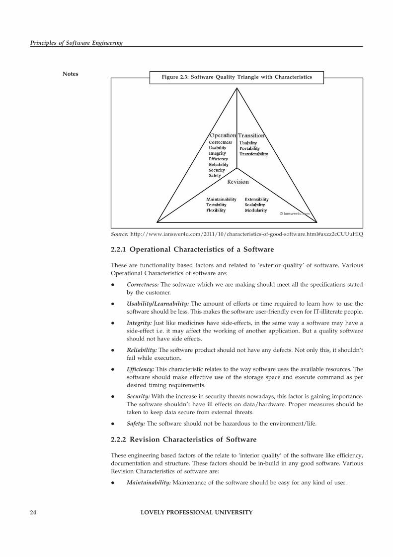
Well these were the obvious things which are expected from any project (and softwaredevelopment is a project in itself). Now lets take a look at Software Quality factors. These set offactors can be easily explained by Software Quality Triangle. The three characteristics of goodapplication software are:
1. Operational Characteristics
2. Transition Characteristic
3. Revision Characteristics
24 LOVELY PROFESSIONAL UNIVERSITY
Principles of Software Engineering
Notes
Source: http://www.ianswer4u.com/2011/10/characteristics-of-good-software.html#axzz2cCUUuHIQ
2.2.1 Operational Characteristics of a Software
These are functionality based factors and related to ‘exterior quality’ of software. VariousOperational Characteristics of software are:
� Correctness: The software which we are making should meet all the specifications statedby the customer.
� Usability/Learnability: The amount of efforts or time required to learn how to use thesoftware should be less. This makes the software user-friendly even for IT-illiterate people.
� Integrity: Just like medicines have side-effects, in the same way a software may have aside-effect i.e. it may affect the working of another application. But a quality softwareshould not have side effects.
� Reliability: The software product should not have any defects. Not only this, it shouldn’tfail while execution.
� Efficiency: This characteristic relates to the way software uses the available resources. Thesoftware should make effective use of the storage space and execute command as perdesired timing requirements.
� Security: With the increase in security threats nowadays, this factor is gaining importance.The software shouldn’t have ill effects on data/hardware. Proper measures should betaken to keep data secure from external threats.
� Safety: The software should not be hazardous to the environment/life.
2.2.2 Revision Characteristics of Software
These engineering based factors of the relate to ‘interior quality’ of the software like efficiency,documentation and structure. These factors should be in-build in any good software. VariousRevision Characteristics of software are:
� Maintainability: Maintenance of the software should be easy for any kind of user.
Figure 2.3: Software Quality Triangle with Characteristics
LOVELY PROFESSIONAL UNIVERSITY 25
Unit 2: Software Processes and Models
Notes� Flexibility: Changes in the software should be easy to make.
� Extensibility: It should be easy to increase the functions performed by it.
� Scalability: It should be very easy to upgrade it for more work (or for more number ofusers).
� Testability: Testing the software should be easy.
� Modularity: Any software is said to made of units and modules which are independent ofeach other. These modules are then integrated to make the final software. If the softwareis divided into separate independent parts that can be modified, tested separately, it hashigh modularity.
2.2.3 Transition Characteristics of the Software
� Interoperability: Interoperability is the ability of software to exchange information withother applications and make use of information transparently.
� Reusability: If we are able to use the software code with some modifications for differentpurpose then we call software to be reusable.
� Portability: The ability of software to perform same functions across all environmentsand platforms, demonstrate its portability.
Importance of any of these factors varies from application-to-application.
!Caution In systems where human life is at stake, integrity and reliability factors must begiven prime importance.
In any business related application usability and maintainability are key factors to be considered.Always remember in Software Engineering, quality of software is everything, therefore try todeliver a product which has all these characteristics and qualities.
Self Assessment
Fill in the blanks:
4. Efficiency of a software relates to the way software uses the available …………………… .
5. …………………… is the ability of software to exchange information with other applicationsand make use of information transparently.
2.3 Water Fall Model
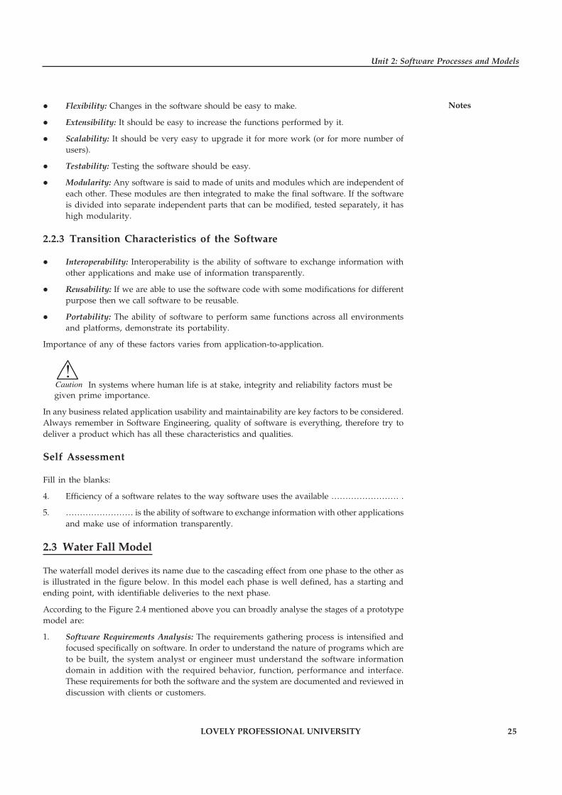
The waterfall model derives its name due to the cascading effect from one phase to the other asis illustrated in the figure below. In this model each phase is well defined, has a starting andending point, with identifiable deliveries to the next phase.
According to the Figure 2.4 mentioned above you can broadly analyse the stages of a prototypemodel are:
1. Software Requirements Analysis: The requirements gathering process is intensified andfocused specifically on software. In order to understand the nature of programs which areto be built, the system analyst or engineer must understand the software informationdomain in addition with the required behavior, function, performance and interface.These requirements for both the software and the system are documented and reviewed indiscussion with clients or customers.
26 LOVELY PROFESSIONAL UNIVERSITY
Principles of Software Engineering
Notes
requirementsanalysis &
softwaredesign
construction
testing
operation &maintenance
specification
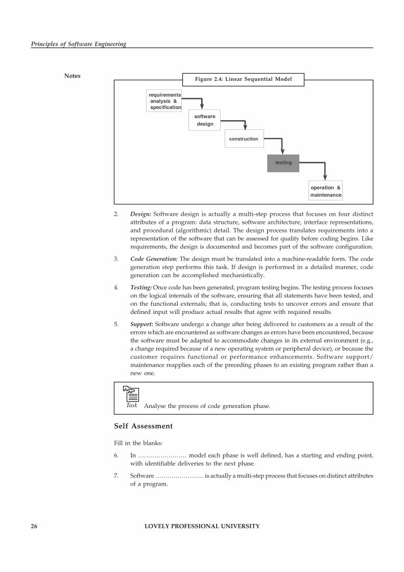
2. Design: Software design is actually a multi-step process that focuses on four distinctattributes of a program: data structure, software architecture, interface representations,and procedural (algorithmic) detail. The design process translates requirements into arepresentation of the software that can be assessed for quality before coding begins. Likerequirements, the design is documented and becomes part of the software configuration.
3. Code Generation: The design must be translated into a machine-readable form. The codegeneration step performs this task. If design is performed in a detailed manner, codegeneration can be accomplished mechanistically.
4. Testing: Once code has been generated, program testing begins. The testing process focuseson the logical internals of the software, ensuring that all statements have been tested, andon the functional externals; that is, conducting tests to uncover errors and ensure thatdefined input will produce actual results that agree with required results.
5. Support: Software undergo a change after being delivered to customers as a result of theerrors which are encountered as software changes as errors have been encountered, becausethe software must be adapted to accommodate changes in its external environment (e.g.,a change required because of a new operating system or peripheral device), or because thecustomer requires functional or performance enhancements. Software support/maintenance reapplies each of the preceding phases to an existing program rather than anew one.
Task Analyse the process of code generation phase.
Self Assessment
Fill in the blanks:
6. In …………………… model each phase is well defined, has a starting and ending point,with identifiable deliveries to the next phase.
7. Software …………………… is actually a multi-step process that focuses on distinct attributesof a program.
Figure 2.4: Linear Sequential Model
LOVELY PROFESSIONAL UNIVERSITY 27
Unit 2: Software Processes and Models
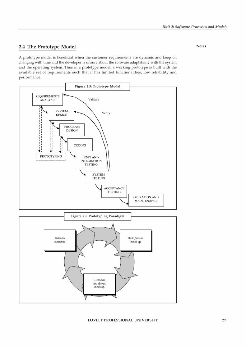
Notes2.4 The Prototype Model
A prototype model is beneficial when the customer requirements are dynamic and keep onchanging with time and the developer is unsure about the software adaptability with the systemand the operating system. Thus in a prototype model, a working prototype is built with theavailable set of requirements such that it has limited functionalities, low reliability andperformance.
REQUIREMENTS ANALYSIS
SYSTEM DESIGN
PROGRAM DESIGN
CODING
PROTOTYPING UNIT AND INTEGRATION
TESTING
ACCEPTANCE TESTING
OPERATION AND MAINTENANCE
Validate
Verify
SYSTEM TESTING
Figure 2.5: Prototype Model
Figure 2.6 Prototyping Paradigm

28 LOVELY PROFESSIONAL UNIVERSITY
Principles of Software Engineering
Notes This prototype is further enhanced by the developer with better understanding of the requirementsand preparation of a final specification document. This working prototype is evaluated by thecustomer and the feedback received helps the developers to get rid of the uncertainties in therequirements and to start a re-iteration of requirements for further clarification. The prototypecan be a usable program with limited functionality but cannot be used as a final product. Thisprototype is thrown away after preparing the final SRS; however the understanding obtainedfrom developing the prototype helps in developing the actual system.
The development of prototype is an additional cost overhead but still the total cost is lower thanthat of the software developed using a waterfall model.
Did u know? The earlier the prototype is developed the speedier would be the softwaredevelopment process.
This model involves a lot of customer interaction which is not always possible.
Self Assessment
Fill in the blanks:
8. In a …………………… model, a working prototype is built with the available set ofrequirements such that it has limited functionalities, low reliability and performance.
9. The earlier the prototype is developed the speedier would be the software ……………………process.
2.5 Iterative Model
An iterative lifecycle model does not attempt to start with a full specification of requirements.Instead, development begins by specifying and implementing just part of the software, whichcan then be reviewed in order to identify further requirements. This process is then repeated,producing a new version of the software for each cycle of the model. Consider an iterativelifecycle model which consists of repeating the following four phases in sequence:
Source: http://www.onestoptesting.com/sdlc-models/iterative-model.asp
A Requirements phase, in which the requirements for the software are gathered and analyzed.Iteration should eventually result in a requirements phase that produces a complete and finalspecification of requirements.
Figure 2.7: Iterative Model

LOVELY PROFESSIONAL UNIVERSITY 29
Unit 2: Software Processes and Models
NotesA Design phase, in which a software solution to meet the requirements is designed. This may bea new design, or an extension of an earlier design.
An Implementation and Test phase, when the software is coded, integrated and tested.
A Review phase, in which the software is evaluated, the current requirements are reviewed, andchanges and additions to requirements proposed.
For each cycle of the model, a decision has to be made as to whether the software produced bythe cycle will be discarded, or kept as a starting point for the next cycle (sometimes referred toas incremental prototyping). Eventually a point will be reached where the requirements arecomplete and the software can be delivered, or it becomes impossible to enhance the software asrequired, and a fresh start has to be made.
The iterative lifecycle model can be likened to producing software by successive approximation.Drawing an analogy with mathematical methods that use successive approximation to arrive ata final solution, the benefit of such methods depends on how rapidly they converge on a solution.
The key to successful use of an iterative software development lifecycle is rigorous validation ofrequirements, and verification (including testing) of each version of the software against thoserequirements within each cycle of the model. The first three phases of the example iterativemodel is in fact an abbreviated form of a sequential V or waterfall lifecycle model. Each cycle ofthe model produces software that requires testing at the unit level, for software integration, forsystem integration and for acceptance. As the software evolves through successive cycles, testshave to be repeated and extended to verify each version of the software.
Task Make distinction between test phase and review phase.
Self Assessment
Fill in the blanks:
10. An …………………… lifecycle model does not attempt to start with a full specification ofrequirements.
11. In …………………… phase, the software is evaluated, the current requirements arereviewed, and changes and additions to requirements proposed.
2.6 Time Boxing Model
To speed up development, parallelism between the different iterations can be employed. Thatis, a new iteration commences before the system produced by the current iteration is released,and hence development of a new release happens in parallel with the development of thecurrent release. By starting an iteration before the previous iteration has completed, it is possibleto reduce the average delivery time for iterations. However, to support parallel execution, eachiteration has to be structured properly and teams have to be organized suitably. The timeboxingmodel proposes an approach for these.
In the timeboxing model, the basic unit of development is a time box, which is of fixed duration.Since the duration is fixed, a key factor in selecting the requirements or features to be built in atime box is what can be fit into the time box. This is in contrast to regular iterative approacheswhere the functionality is selected and then the time to deliver is determined.
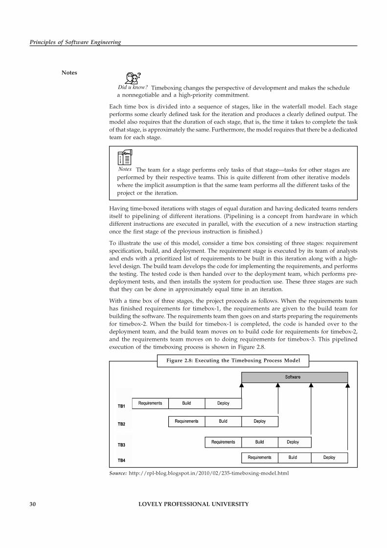
30 LOVELY PROFESSIONAL UNIVERSITY
Principles of Software Engineering
Notes
Did u know? Timeboxing changes the perspective of development and makes the schedulea nonnegotiable and a high-priority commitment.
Each time box is divided into a sequence of stages, like in the waterfall model. Each stageperforms some clearly defined task for the iteration and produces a clearly defined output. Themodel also requires that the duration of each stage, that is, the time it takes to complete the taskof that stage, is approximately the same. Furthermore, the model requires that there be a dedicatedteam for each stage.
Notes The team for a stage performs only tasks of that stage—tasks for other stages areperformed by their respective teams. This is quite different from other iterative modelswhere the implicit assumption is that the same team performs all the different tasks of theproject or the iteration.
Having time-boxed iterations with stages of equal duration and having dedicated teams rendersitself to pipelining of different iterations. (Pipelining is a concept from hardware in whichdifferent instructions are executed in parallel, with the execution of a new instruction startingonce the first stage of the previous instruction is finished.)
To illustrate the use of this model, consider a time box consisting of three stages: requirementspecification, build, and deployment. The requirement stage is executed by its team of analystsand ends with a prioritized list of requirements to be built in this iteration along with a high-level design. The build team develops the code for implementing the requirements, and performsthe testing. The tested code is then handed over to the deployment team, which performs pre-deployment tests, and then installs the system for production use. These three stages are suchthat they can be done in approximately equal time in an iteration.
With a time box of three stages, the project proceeds as follows. When the requirements teamhas finished requirements for timebox-1, the requirements are given to the build team forbuilding the software. The requirements team then goes on and starts preparing the requirementsfor timebox-2. When the build for timebox-1 is completed, the code is handed over to thedeployment team, and the build team moves on to build code for requirements for timebox-2,and the requirements team moves on to doing requirements for timebox-3. This pipelinedexecution of the timeboxing process is shown in Figure 2.8.
Source: http://rpl-blog.blogspot.in/2010/02/235-timeboxing-model.html
Figure 2.8: Executing the Timeboxing Process Model
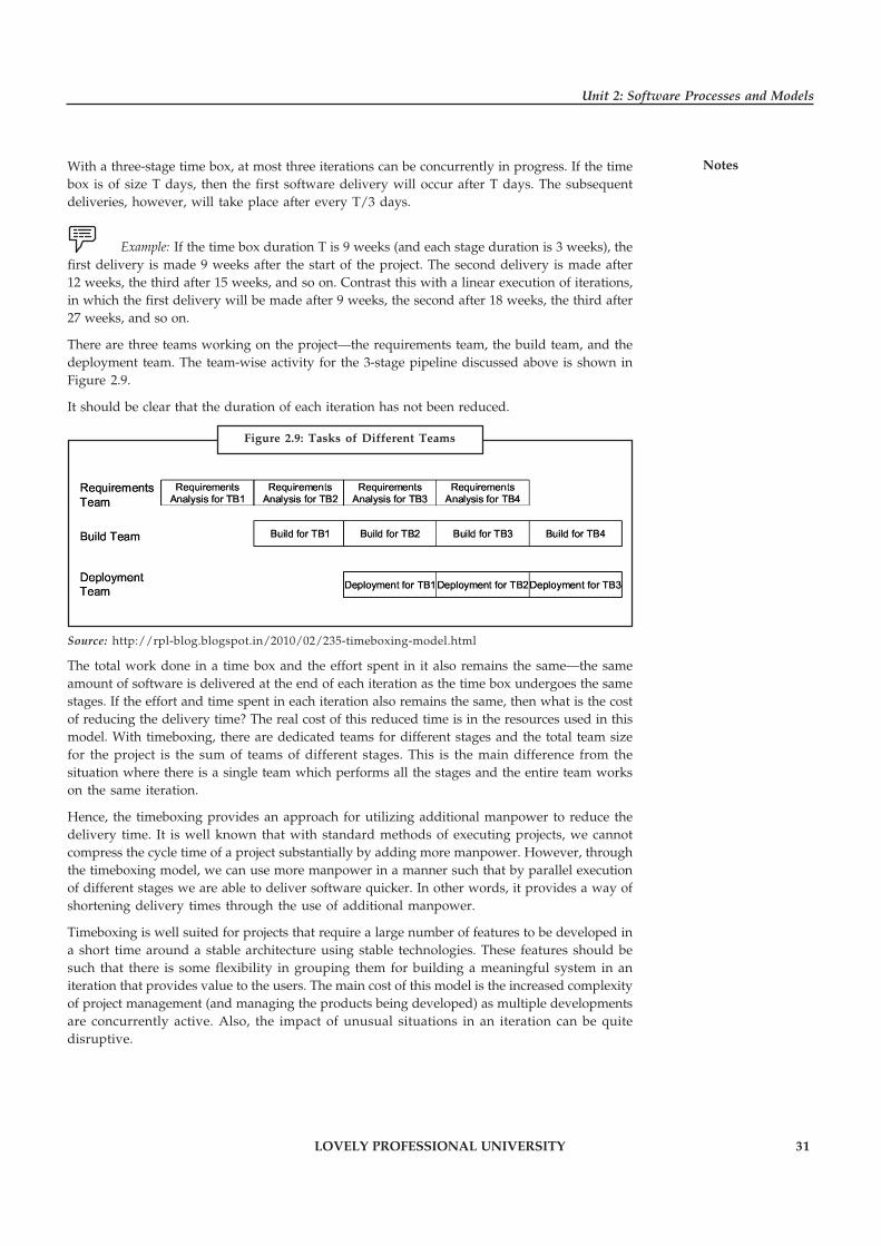
LOVELY PROFESSIONAL UNIVERSITY 31
Unit 2: Software Processes and Models
NotesWith a three-stage time box, at most three iterations can be concurrently in progress. If the timebox is of size T days, then the first software delivery will occur after T days. The subsequentdeliveries, however, will take place after every T/3 days.
Example: If the time box duration T is 9 weeks (and each stage duration is 3 weeks), thefirst delivery is made 9 weeks after the start of the project. The second delivery is made after12 weeks, the third after 15 weeks, and so on. Contrast this with a linear execution of iterations,in which the first delivery will be made after 9 weeks, the second after 18 weeks, the third after27 weeks, and so on.
There are three teams working on the project—the requirements team, the build team, and thedeployment team. The team-wise activity for the 3-stage pipeline discussed above is shown inFigure 2.9.
It should be clear that the duration of each iteration has not been reduced.
Source: http://rpl-blog.blogspot.in/2010/02/235-timeboxing-model.html
The total work done in a time box and the effort spent in it also remains the same—the sameamount of software is delivered at the end of each iteration as the time box undergoes the samestages. If the effort and time spent in each iteration also remains the same, then what is the costof reducing the delivery time? The real cost of this reduced time is in the resources used in thismodel. With timeboxing, there are dedicated teams for different stages and the total team sizefor the project is the sum of teams of different stages. This is the main difference from thesituation where there is a single team which performs all the stages and the entire team workson the same iteration.
Hence, the timeboxing provides an approach for utilizing additional manpower to reduce thedelivery time. It is well known that with standard methods of executing projects, we cannotcompress the cycle time of a project substantially by adding more manpower. However, throughthe timeboxing model, we can use more manpower in a manner such that by parallel executionof different stages we are able to deliver software quicker. In other words, it provides a way ofshortening delivery times through the use of additional manpower.
Timeboxing is well suited for projects that require a large number of features to be developed ina short time around a stable architecture using stable technologies. These features should besuch that there is some flexibility in grouping them for building a meaningful system in aniteration that provides value to the users. The main cost of this model is the increased complexityof project management (and managing the products being developed) as multiple developmentsare concurrently active. Also, the impact of unusual situations in an iteration can be quitedisruptive.
Figure 2.9: Tasks of Different Teams
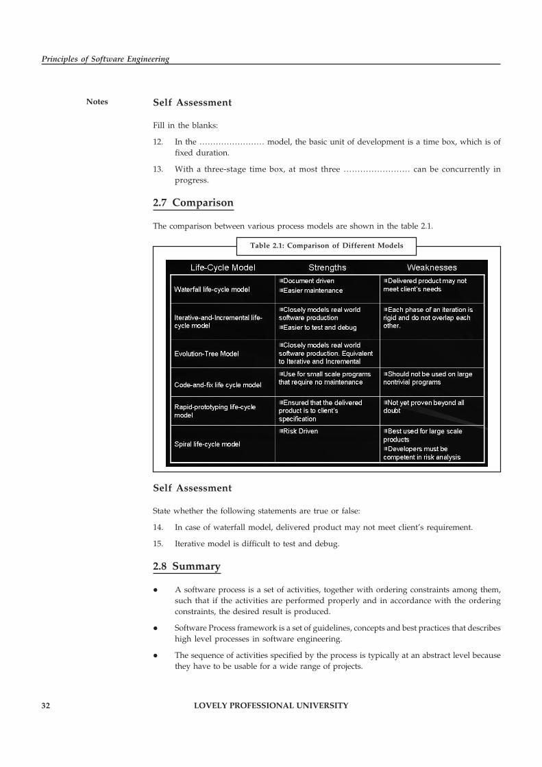
32 LOVELY PROFESSIONAL UNIVERSITY
Principles of Software Engineering
Notes Self Assessment
Fill in the blanks:
12. In the …………………… model, the basic unit of development is a time box, which is offixed duration.
13. With a three-stage time box, at most three …………………… can be concurrently inprogress.
2.7 Comparison
The comparison between various process models are shown in the table 2.1.
Self Assessment
State whether the following statements are true or false:
14. In case of waterfall model, delivered product may not meet client’s requirement.
15. Iterative model is difficult to test and debug.
2.8 Summary
� A software process is a set of activities, together with ordering constraints among them,such that if the activities are performed properly and in accordance with the orderingconstraints, the desired result is produced.
� Software Process framework is a set of guidelines, concepts and best practices that describeshigh level processes in software engineering.
� The sequence of activities specified by the process is typically at an abstract level becausethey have to be usable for a wide range of projects.
Table 2.1: Comparison of Different Models
LOVELY PROFESSIONAL UNIVERSITY 33
Unit 2: Software Processes and Models
Notes� A software process model is a simplified description of a software process, which ispresented from a particular perspective.
� In waterfall model each phase is well defined, has a starting and ending point, withidentifiable deliveries to the next phase.
� In a prototype model, a working prototype is built with the available set of requirementssuch that it has limited functionalities, low reliability and performance.
� An iterative lifecycle model does not attempt to start with a full specification ofrequirements.
� In the timeboxing model, the basic unit of development is a time box, which is of fixedduration.
2.9 Keywords
A Workflow Model: This shows the sequence of activities in the process along with their inputs,outputs and dependencies.
Dataflow or Activity Model: This represents the process as a set of activities each of whichcarries out some data transformation.
Design Phase: A Design phase is a phase in which a software solution to meet the requirementsis designed.
Prototype Model: It is a model in which a working prototype is built with the available set ofrequirements such that it has limited functionalities, low reliability and performance.
Requirements Phase: A Requirements phase is a phase in which the requirements for the softwareare gathered and analyzed.
Software Processes: Software processes are the activities involved in producing and evolving asoftware system.
Software Process Framework: It is a set of guidelines, concepts and best practices that describeshigh level processes in software engineering.
Software Process Model: A software process model is a simplified description of a softwareprocess, which is presented from a particular perspective.
2.10 Review Questions
1. Explain the concept of software processes.
2. Describe the relation between Processes, Projects and Products.
3. Explain the concept of software process model with examples.
4. Discuss the number of different general models or paradigms of software development.
5. Discuss the characteristics of a Software Model.
6. Explain the working of waterfall model.
7. Describe the phases included in iterative model.
8. What is time boxing model? Illustrate the working of Time Boxing Model.
9. With a three-stage time box in time boxing model, at most three iterations can beconcurrently in progress. Comment.
10. Compare and contrast waterfall model and iterative model.

34 LOVELY PROFESSIONAL UNIVERSITY
Principles of Software Engineering
Notes Answers: Self Assessment
1. software process 2. Software Process framework
3. workflow model 4. Resources
5. Interoperability 6. Waterfall
7. design 8. Prototype
9. development 10. Iterative
11. Review 12. Timeboxing
13. iterations 14. True
15. False
2.11 Further Readings
Books Rajib Mall, Fundamentals of Software Engineering, 2nd Edition, PHI.
Richard Fairpy, Software Engineering Concepts, Tata McGraw Hill, 1997.
R.S. Pressman, Software Engineering – A Practitioner’s Approach, 5th Edition, TataMcGraw Hill Higher education.
Sommerville, Software Engineering, 6th Edition, Pearson Education.
Online links http://www.ijcsi.org/papers/7-5-94-101.pdf
http://people.sju.edu/~jhodgson/se/models.html
http://www.ics.uci.edu/~wscacchi/Papers/SE-Encyc/Process-Models-SE-Encyc.pdf

LOVELY PROFESSIONAL UNIVERSITY 35
Unit 3: Software Requirements
NotesUnit 3: Software Requirements
CONTENTS
Objectives
Introduction
3.1 Problem Analysis
3.1.1 Data Flow
3.2 Object Oriented Modelling
3.2.1 Functional Models
3.2.2 Behavioral Models
3.3 Prototyping
3.3.1 Prototyping Pitfalls
3.3.2 Prototyping Opportunities
3.3.3 Selecting the Prototyping Approach
3.3.4 Prototyping Methods and Tools
3.4 Software Requirements Specification Document
3.4.1 Characteristics of a Good SRS
3.4.2 Components of SRS
3.4.3 Specification Language
3.4.4 Structure of Document
3.5 Summary
3.6 Keywords
3.7 Review Questions
3.8 Further Readings
Objectives
After studying this unit, you will be able to:
� Discuss problem analysis
� Explain the concept of object oriented modelling and prototyping
� Describe the characteristics and components of SRS document.
� Explain software requirement specification language
� Discuss the structure of document
Introduction
The Software Requirements Specification is developed as a consequence of analysis. Requirementsanalysis is a software engineering task that bridges the gap between system level engineering
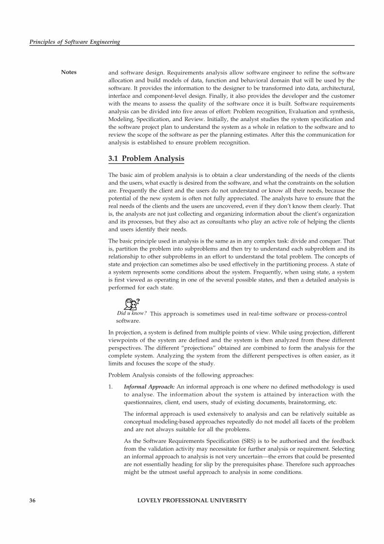
36 LOVELY PROFESSIONAL UNIVERSITY
Principles of Software Engineering
Notes and software design. Requirements analysis allow software engineer to refine the softwareallocation and build models of data, function and behavioral domain that will be used by thesoftware. It provides the information to the designer to be transformed into data, architectural,interface and component-level design. Finally, it also provides the developer and the customerwith the means to assess the quality of the software once it is built. Software requirementsanalysis can be divided into five areas of effort: Problem recognition, Evaluation and synthesis,Modeling, Specification, and Review. Initially, the analyst studies the system specification andthe software project plan to understand the system as a whole in relation to the software and toreview the scope of the software as per the planning estimates. After this the communication foranalysis is established to ensure problem recognition.
3.1 Problem Analysis
The basic aim of problem analysis is to obtain a clear understanding of the needs of the clientsand the users, what exactly is desired from the software, and what the constraints on the solutionare. Frequently the client and the users do not understand or know all their needs, because thepotential of the new system is often not fully appreciated. The analysts have to ensure that thereal needs of the clients and the users are uncovered, even if they don’t know them clearly. Thatis, the analysts are not just collecting and organizing information about the client’s organizationand its processes, but they also act as consultants who play an active role of helping the clientsand users identify their needs.
The basic principle used in analysis is the same as in any complex task: divide and conquer. Thatis, partition the problem into subproblems and then try to understand each subproblem and itsrelationship to other subproblems in an effort to understand the total problem. The concepts ofstate and projection can sometimes also be used effectively in the partitioning process. A state ofa system represents some conditions about the system. Frequently, when using state, a systemis first viewed as operating in one of the several possible states, and then a detailed analysis isperformed for each state.
Did u know? This approach is sometimes used in real-time software or process-controlsoftware.
In projection, a system is defined from multiple points of view. While using projection, differentviewpoints of the system are defined and the system is then analyzed from these differentperspectives. The different “projections” obtained are combined to form the analysis for thecomplete system. Analyzing the system from the different perspectives is often easier, as itlimits and focuses the scope of the study.
Problem Analysis consists of the following approaches:
1. Informal Approach: An informal approach is one where no defined methodology is usedto analyse. The information about the system is attained by interaction with thequestionnaires, client, end users, study of existing documents, brainstorming, etc.
The informal approach is used extensively to analysis and can be relatively suitable asconceptual modeling-based approaches repeatedly do not model all facets of the problemand are not always suitable for all the problems.
As the Software Requirements Specification (SRS) is to be authorised and the feedbackfrom the validation activity may necessitate for further analysis or requirement. Selectingan informal approach to analysis is not very uncertain—the errors that could be presentedare not essentially heading for slip by the prerequisites phase. Therefore such approachesmight be the utmost useful approach to analysis in some conditions.

LOVELY PROFESSIONAL UNIVERSITY 37
Unit 3: Software Requirements
Notes
Notes Several fact finding methods are used to collect comprehensive information aboutevery aspect of an present system.
2. Shadowing: Shadowing provides an effective means to discover what is currently beingdone in a business. Shadowing is a good way to get an idea of what a person does on a day-to-day basis. However, you might not be able to observe all the tasks during shadowingbecause more than likely the person will not, during that session, perform all the tasks heor she is assigned. For example, accounting people might create reports at the end of themonth, developers might create status reports on a weekly basis, and management mightschedule status meetings only biweekly. In addition, you can also learn the purpose ofperforming a specific task. To gather as much information as possible, you need to encouragethe user to explain the reasons for performing a task in as much detail as possible.
Shadowing can be both passive and active. When performing passive shadowing, youobserve the user and listen to any explanations that the user might provide. Whenperforming active shadowing, you ask questions as the user explains events and activities.You might also be given the opportunity to perform some of the tasks, at the user’sdiscretion.
3. Interviews: In interview is a one-on-one meeting between a member of the project teamand a user. The quality of the information a team gathers depends on the skills of both theinterviewer and the interviewee. An interviewer can learn a great deal about the difficultiesand limitations of the current solution. Interviews provide the opportunity to ask a widerange of questions about topics that you cannot observe by means of shadowing. Shadowingis not the best option for gathering information about tasks such as management-levelactivities; long-term activities that span weeks, months, or years; or processes that requirelittle or no human intervention. An example of a process that requires no humanintervention is the automatic bill paying service provided by financial institutions. Forgathering information about such activities and processes, you need to conduct interviews.
3.1.1 Data Flow
Data flow diagrams (also called data flow graphs) are commonly used during problem analysis.Data flow diagrams (DFDs) are quite general and are not limited to problem analysis for softwarerequirements specification. They were in use long before the software engineering disciplinebegan. DFDs are very useful in understanding a system and can be effectively used duringanalysis.
A DFD shows the flow of data through a system. It views a system as a function that transformsthe inputs into desired outputs. Any complex system will not perform this transformation in a“single step,” and data will typically undergo a series of transformations before it becomes theoutput. The DFD aims to capture the transformations that take place within a system to the inputdata so that eventually the output data is produced. The agent that performs the transformationof data from one state to another is called a process (or a bubble). Thus, a DFD shows themovement of data through the different transformations or processes in the system. The processesare shown by named circles and data flows are represented by named arrows entering orleaving the bubbles. A rectangle represents a source or sink and is a net originator or consumerof data. A source or a sink is typically outside the main system of study.
Data flow diagramming rules:
1. Processes cannot have only outputs, cannot have only inputs, and must have a verb phraselabel.

38 LOVELY PROFESSIONAL UNIVERSITY
Principles of Software Engineering
Notes 2. Data can only move to a data store from a process, not from another data store or anoutside source.
3. Similarly, data can only be moved to an outside sink or to another data store by a process.
4. Data to and from external sources and sinks can only be moved by processes.
5. Data flows move in one direction only.
6. Both branches of a forked or a joined data flow must represent the same type of data.
7. A data flow cannot return to the process from which it originated.
Self Assessment
Fill in the blanks:
1. A …………………… of a system represents some conditions about the system.
2. In ……………………, a system is defined from multiple points of view.
3. The different “projections” obtained are combined to form the …………………… for thecomplete system.
4. A …………………… shows the flow of data through a system.
3.2 Object Oriented Modelling
Object-Oriented Software Engineering (OOSE) is a software design technique that is used insoftware design in object-oriented programming. It includes a requirements, an analysis, adesign, an implementation and a testing model. You create functional models to gain a betterunderstanding of the actual entity to be built. When the entity is a physical thing (a building, aplane, a machine), we can build a model that is identical in form and shape but smaller in scale.However, when the entity to be built is software, our model must take a different form. It mustbe capable of representing the information that software transforms, the functions (and sub-functions) that enable the transformation to occur, and the behavior of the system as thetransformation is taking place.
Notes The second and third operational analysis principles require that we build modelsof function and behavior.
3.2.1 Functional Models
Software transforms information, and in order to accomplish this, it must perform at least threegeneric functions: input, processing, and output. When functional models of an application arecreated, the software engineer focuses on problem specific functions. The functional modelbegins with a single context level model (i.e., the name of the software to be built). Over a seriesof iterations, more and more functional detail is provided, until a thorough delineation of allsystem functionality is represented.
3.2.2 Behavioral Models
Most software responds to events from the outside world. This stimulus/response characteristicforms the basis of the behavioral model. A computer program always exists in some state an
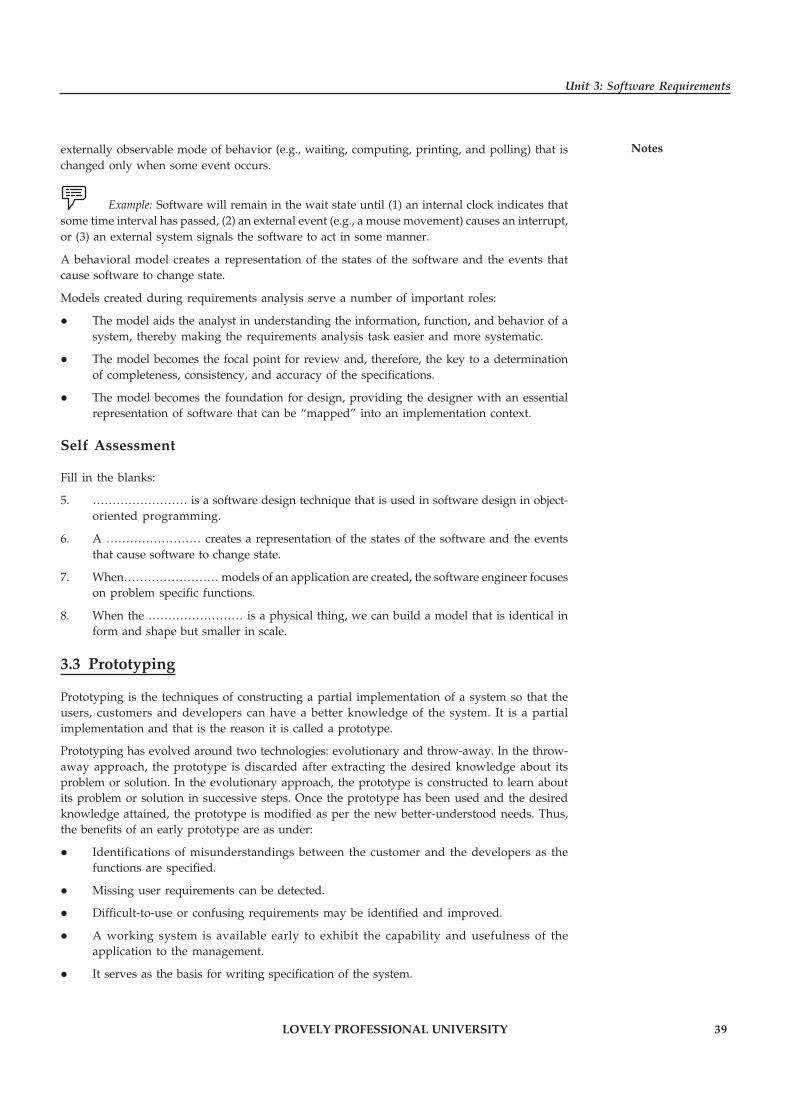
LOVELY PROFESSIONAL UNIVERSITY 39
Unit 3: Software Requirements
Notesexternally observable mode of behavior (e.g., waiting, computing, printing, and polling) that ischanged only when some event occurs.
Example: Software will remain in the wait state until (1) an internal clock indicates thatsome time interval has passed, (2) an external event (e.g., a mouse movement) causes an interrupt,or (3) an external system signals the software to act in some manner.
A behavioral model creates a representation of the states of the software and the events thatcause software to change state.
Models created during requirements analysis serve a number of important roles:
� The model aids the analyst in understanding the information, function, and behavior of asystem, thereby making the requirements analysis task easier and more systematic.
� The model becomes the focal point for review and, therefore, the key to a determinationof completeness, consistency, and accuracy of the specifications.
� The model becomes the foundation for design, providing the designer with an essentialrepresentation of software that can be “mapped” into an implementation context.
Self Assessment
Fill in the blanks:
5. …………………… is a software design technique that is used in software design in object-oriented programming.
6. A …………………… creates a representation of the states of the software and the eventsthat cause software to change state.
7. When…………………… models of an application are created, the software engineer focuseson problem specific functions.
8. When the …………………… is a physical thing, we can build a model that is identical inform and shape but smaller in scale.
3.3 Prototyping
Prototyping is the techniques of constructing a partial implementation of a system so that theusers, customers and developers can have a better knowledge of the system. It is a partialimplementation and that is the reason it is called a prototype.
Prototyping has evolved around two technologies: evolutionary and throw-away. In the throw-away approach, the prototype is discarded after extracting the desired knowledge about itsproblem or solution. In the evolutionary approach, the prototype is constructed to learn aboutits problem or solution in successive steps. Once the prototype has been used and the desiredknowledge attained, the prototype is modified as per the new better-understood needs. Thus,the benefits of an early prototype are as under:
� Identifications of misunderstandings between the customer and the developers as thefunctions are specified.
� Missing user requirements can be detected.
� Difficult-to-use or confusing requirements may be identified and improved.
� A working system is available early to exhibit the capability and usefulness of theapplication to the management.
� It serves as the basis for writing specification of the system.

40 LOVELY PROFESSIONAL UNIVERSITY
Principles of Software Engineering
Notes The differences between the throw-away and evolutionary prototyping have been illustrated inthe Table 3.1.
Sr. No.
Approach and Characteristics
Throw-away Evolutionary
1 Development approach Quick and dirty. No rigor. No sloppiness. Rigorous
2 What to build Build only difficult parts Build understood parts first and build on solid foundations
3 Design drivers Optimize development time Optimize modifiability
4 Ultimate objective Throw it away Evolve it
3.3.1 Prototyping Pitfalls
A common problem with using prototyping technology is high expectations for productivitywith insufficient effort. It can have execution inefficiencies with the associated tools and thismay be considered as a negative aspect of prototyping.
The process of providing an early feedback to the user results in a problem related to thebehavior of end-user and developers. An end-user with a poor past development experience canbe biased with the developments in future.
3.3.2 Prototyping Opportunities
Software prototyping cannot be got rid of totally. The benefits of prototyping are obvious andestablished. The end user cannot expect the developer to come up with a full fledged systemwith incomplete software needs.
Prototyping must be used on critical portions of the existing software. The idea of completelyre-engineering software is not a good idea. Total re-engineering must be planned and shouldnot be used in reaction to a crisis situation.
Software prototyping must be implemented in an organization with the help of training, case-studies and library development. The end user involvement can be enhanced when therequirements are prototyped and communicated before starting with the development.Moreover, during the maintenance stage, the requirement change should lead to prototypebeing enhanced before the actual changes are confirmed.
3.3.3 Selecting the Prototyping Approach
The prototyping paradigm can be either close-ended or open-ended. The close-ended approachis often called throwaway prototyping. Using this approach, a prototype serves solely as arough demonstration of requirements. It is then discarded, and the software is engineered usinga different paradigm. An open-ended approach, called evolutionary prototyping, uses theprototype as the first part of an analysis activity that will be continued into design andconstruction.
Did u know? The prototype of the software is the first evolution of the finished system.
Before a close-ended or open-ended approach can be chosen, it is necessary to determine whetherthe system to be built is amenable to prototyping. A number of prototyping candidacy factors
Table 3.1: Differences between Throw-away and Evolutionary Prototyping
LOVELY PROFESSIONAL UNIVERSITY 41
Unit 3: Software Requirements
Notescan be defined: application area, application complexity, customer characteristics, and projectcharacteristics.
In general, any application that creates dynamic visual displays, interacts heavily with a user, ordemands algorithms or combinatorial processing that must be developed in an evolutionaryfashion is a candidate for prototyping. However, these application areas must be weighedagainst application complexity. If a candidate application (one that has the characteristics noted)will require the development of tens of thousands of lines of code before any demonstrablefunction can be performed, it is likely to be too complex for prototyping. If, however, thecomplexity can be partitioned, it may still be possible to prototype portions of the software.
Because the customer must interact with the prototype in later steps, it is essential that(1) customer resources be committed to the evaluation and refinement of the prototype and(2) the customer is capable of making requirements decisions in a timely fashion. Finally, thenature of the development project will have a strong bearing on the efficacy of prototyping. Isproject management willing and able to work with the prototyping method? Are prototypingtools available? Do developers have experience with prototyping methods? Andriole suggestssix questions and indicates typical sets of answers and the corresponding suggested prototypingapproach.
3.3.4 Prototyping Methods and Tools
For software prototyping to be effective, a prototype must be developed rapidly so that thecustomer may assess results and recommend changes. To conduct rapid prototyping, threegeneric classes of methods and tools are available:
� Fourth Generation Techniques: Fourth generation techniques (4GT) encompass a broadarray of database query and reporting languages, program and application generators,and other very high-level non-procedural languages. Because 4GT enable the softwareengineer to generate executable code quickly, they are ideal for rapid prototyping.
� Reusable Software Components: Another approach to rapid prototyping is to assemble,rather than build, the prototype by using a set of existing software components. Meldingprototyping and program component reuse will work only if a library system is developedso that components that do exist can be cataloged and then retrieved.
Notes It should be noted that an existing software product can be used as a prototype fora “new, improved” competitive product. In a way, this is a form of reusability for softwareprototyping.
Table 3.2: Selecting appropriate Prototyping Approach
42 LOVELY PROFESSIONAL UNIVERSITY
Principles of Software Engineering
Notes � Formal Specification and Prototyping Environments: Over the past two decades, a numberof formal specification languages and tools have been developed as a replacement fornatural language specification techniques. Today, developers of these formal languagesare in the process of developing interactive environments that (1) enable an analyst tointeractively create language-based specifications of a system or software, (2) invokeautomated tools that translate the language-based specifications into executable code, and(3) enable the customer to use the prototype executable code to refine formal requirements.
Task Make distinction between Throw-away and Evolutionary Prototyping.
Self Assessment
Fill in the blanks:
9. …………………… is the techniques of constructing a partial implementation of a system.
10. In the …………………… approach, the prototype is discarded after extracting the desiredknowledge about its problem or solution.
11. In the …………………… approach, the prototype is constructed to learn about its problemor solution in successive steps.
12. The …………………… approach is often called throwaway prototyping.
3.4 Software Requirements Specification Document
The SRS (Software Requirements Specification) contains specifications for a particular softwareproduct, program or a set of programs that perform a particular function in a specific environment.It serves a number of purposes depending upon its creator.
1. SRS could be written by the customer. It must address the needs and expectations of theusers.
2. SRS could be written by the developer of the system. It serves a different purpose andmentions the contrast between the customer and the developer.
3.4.1 Characteristics of a Good SRS
An SRS should have the following characteristics:
� Correct: An SRS is said to be correct if it contains the requirements that the software shouldmeet. The correctness cannot be measured through a tool or a procedure.
� Unambiguous: An SRS is unambiguous only if the requirements contained in it have onlyone interpretation. It must be unambiguous to both who create and who use it. However,the two groups may use different languages for description. But the language should be anatural language that can be easily understood by both the groups.
� Complete: An SRS is complete if it includes the following:
� All significant requirements related to functionality, performance, design, attributesor external interfaces.
� Definition of the software responses to all possible input classes in all possiblesituations.

LOVELY PROFESSIONAL UNIVERSITY 43
Unit 3: Software Requirements
Notes� Full references and labels to figures, tables, diagrams and the definition of all termsand units of measure.
� Consistent: An SRS is consistent if no subset of a requirement defines it in entirety. Theconflicts can be of three types:
� Characteristics of real-world objects.
� Logical or temporal conflicts.
� The same real world object defined in more than one places in different terminologies.
� Ranked for Importance and Stability: An SRS is ranked for importance and stability ifeach requirement contained in it has an identifier indicating its importance or stability ofthat requirement. Another way to implement the importance of requirements is to classifythem as essential, conditional and optional.
� Verifiable: An SRS is verifiable if every requirement contained in it is verifiable i.e. thereexists some defined method to judge if a software meets all the requirements. Non-verifiable requirements should be removed or revised.
� Modifiable: An SRS is modifiable if its styles and structures can be retained easily,completely and consistently while changing a requirement.
� Traceable: An SRS is traceable if each of its requirements is clear and can be referencedin future development or enhancement documentation. Two types of traceabilityare recommended:
� Backward Traceability: This depends upon each requirement explicitly referencing itssource in earlier documents.
� Forward Traceability: This depends upon each requirement in SRS having a uniquename or reference number.
3.4.2 Components of SRS
Completeness of specifications is difficult to achieve and even more difficult to verify. Havingguidelines about what different things an SRS should specify will help in completely specifyingthe requirements. The basic issues an SRS must address are:
� Functionality
� Performance
� Design constraints imposed on an implementation
� External interfaces
Functional requirements specify the expected behavior of the system—which outputs should beproduced from the given inputs. They describe the relationship between the input and output ofthe system.
!Caution For each functional requirement, a detailed description of all the data inputs andtheir source, the units of measure, and the range of valid inputs must be specified.
All the operations to be performed on the input data to obtain the output should be specified.This includes specifying the validity checks on the input and output data, parameters affected bythe operation, and equations or other logical operations that must be used to transform theinputs into corresponding outputs.
44 LOVELY PROFESSIONAL UNIVERSITY
Principles of Software Engineering
NotesExample: If there is a formula for computing the output, it should be specified.
An important part of the specification is the system behavior in abnormal situations, like invalidinput (which can occur in many ways) or error during computation. The functional requirementmust clearly state what the system should do if such situations occur. Specifically, it shouldspecify the behavior of the system for invalid inputs and invalid outputs. Furthermore, behaviorfor situations where the input is valid but the normal operation cannot be performed shouldalso be specified.
Example: An example of this situation is a reservation system, where a reservationcannot be made even for a valid request if there is no availability.
In short, the system behavior for all foreseen inputs and all foreseen system states should bespecified.
The performance requirements part of an SRS specifies the performance constraints on thesoftware system. All the requirements relating to the performance characteristics of the systemmust be clearly specified. There are two types of performance requirements: static and dynamic.Static requirements are those that do not impose constraint on the execution characteristics ofthe system. These include requirements like the number of terminals to be supported, thenumber of simultaneous users to be supported, and the number of files that the system has toprocess and their sizes. These are also called capacity requirements of the system.
Dynamic requirements specify constraints on the execution behavior of the system. Thesetypically include response time and throughput constraints on the system. Response time is theexpected time for the completion of an operation under specified circumstances. Throughput isthe expected number of operations that can be performed in a unit time.
Example: The SRS may specify the number of transactions that must be processed perunit time, or what the response time for a particular command should be. Acceptable ranges ofthe different performance parameters should be specified, as well as acceptable performance forboth normal and peak workload conditions.
All of these requirements should be stated in measurable terms. Requirements such as “responsetime should be good” or the system must be able to “process all the transactions quickly” are notdesirable because they are imprecise and not verifiable. Instead, statements like “the responsetime of command x should be less than one second 90% of the times” or “a transaction should beprocessed in less than one second 98% of the times” should be used to declare performancespecifications.
There are a number of factors in the client’s environment that may restrict the choices of adesigner leading to design constraints. Such factors include standards that must be followed,resource limits, operating environment, reliability and security requirements, and policies thatmay have an impact on the design of the system. An SRS should identify and specify all suchconstraints.
Example: Some examples of these are:
� Standards Compliance: This specifies the requirements for the standards the system mustfollow. The standards may include the report format and accounting procedures. Theremay be audit requirements which may require logging of operations.
LOVELY PROFESSIONAL UNIVERSITY 45
Unit 3: Software Requirements
Notes� Hardware Limitations: The software may have to operate on some existing orpredetermined hardware, thus imposing restrictions on the design. Hardware limitationscan include the type of machines to be used, operating system available on the system,languages supported, and limits on primary and secondary storage. Reliability and FaultTolerance: Fault tolerance requirements can place a major constraint on how the system isto be designed, as they make the system more complex and expensive. Recoveryrequirements are often an integral part here, detailing what the system should do if somefailure occurs to ensure certain properties.
� Security: Security requirements are becoming increasingly important. These requirementsplace restrictions on the use of certain commands, control access to data, provide differentkinds of access requirements for different people, require the use of passwords andcryptography techniques, and maintain a log of activities in the system. They may alsorequire proper assessment of security threats, proper programming techniques, and useof tools to detect flaws like buffer overflow.
In the external interface specification part, all the interactions of the software with people,hardware, and other software should be clearly specified. For the user interface, the characteristicsof each user interface of the software product should be specified. User interface is becomingincreasingly important and must be given proper attention. A preliminary user manual shouldbe created with all user commands, screen formats, an explanation of how the system willappear to the user, and feedback and error messages. Like other specifications, these requirementsshould be precise and verifiable. So, a statement like “the system should be user friendly”should be avoided and statements like “commands should be no longer than six characters” or“command names should reflect the function they perform” used.
For hardware interface requirements, the SRS should specify the logical characteristics of eachinterface between the software product and the hardware components. If the software is toexecute on existing hardware or on predetermined hardware, all the characteristics of thehardware, including memory restrictions, should be specified. In addition, the current use andload characteristics of the hardware should be given.
The interface requirement should specify the interface with other software the system will useor that will use the system. This includes the interface with the operating system and otherapplications.
!Caution The message content and format of each interface should be specified.
3.4.3 Specification Language
Unlike formal language that allows developers and designers some latitude, the natural languageof software requirements specifications must be exact, without ambiguity, and precise becausethe design specification, statement of work, and other project documents are what drive thedevelopment of the final product. That final product must be tested and validated against thedesign and original requirements. Specification language that allows for interpretation of keyrequirements will not yield a satisfactory final product and will likely lead to cost overruns,extended schedules, and missed deliverable deadlines.
Table 3.3 shows the fundamental characteristics of a quality SRS.

46 LOVELY PROFESSIONAL UNIVERSITY
Principles of Software Engineering
Notes
SRS Quality Characteristic
What It Means
Complete SRS defines precisely all the go-live situations that will be encountered and the system’s capability to successfully address them.
Consistent SRS capability functions and performance levels are compatible, and the required quality features (security, reliability, etc.) do not negate those capability functions. For example, the only electric hedge trimmer that is safe is one that is stored in a box and not connected to any electrical cords or outlets.
Accurate SRS precisely defines the system’s capability in a real-world environment, as well as how it interfaces and interacts with it. This aspect of requirements is a significant problem area for many SRSs.
Modifiable The logical, hierarchical structure of the SRS should facilitate any necessary modifications (grouping related issues together and separating them from unrelated issues makes the SRS easier to modify).
Ranked Individual requirements of an SRS are hierarchically arranged according to stability, security, perceived ease/difficulty of implementation, or other parameter that helps in the design of that and subsequent documents.
Testable An SRS must be stated in such a manner that unambiguous assessment criteria (pass/fail or some quantitative measure) can be derived from the SRS itself.
Traceable Each requirement in an SRS must be uniquely identified to a source (use case, government requirement, industry standard, etc.)
Unambiguous SRS must contain requirements statements that can be interpreted in one way only. This is another area that creates significant problems for SRS development because of the use of natural language.
Valid A valid SRS is one in which all parties and project participants can understand, analyze, accept, or approve it. This is one of the main reasons SRSs are written using natural language.
Verifiable A verifiable SRS is consistent from one level of abstraction to another. Most attributes of a specification are subjective and a conclusive assessment of quality requires a technical review by domain experts. Using indicators of strength and weakness provide some evidence that preferred attributes are or are not present.
What makes an SRS “good?” A quality specification is one that fully addresses all the customerrequirements for a particular product or system. That’s part of the answer. While many qualityattributes of an SRS are subjective, we do need indicators or measures that provide a sense ofhow strong or weak the language is in an SRS. A “strong” SRS is one in which the requirementsare tightly, unambiguously, and precisely defined in such a way that leaves no other interpretationor meaning to any individual requirement.
There are dozens of NASA requirements specifications that revealed nine categories of SRSquality indicators. The individual components in each category are words, phrases, and sentencestructures that are related to quality attributes. The nine categories fall into two classes: thoserelated to individual specification statements, and those related to the total SRS document.Table 3.4 summarizes the classes, categories, and components of these quality indicators.
Imperatives: Words and phrases that command the presence of some feature, function, or deliverable. They are listed below in decreasing order of strength.
Shall Used to dictate the provision of a functional capability.
Must or must not Most often used to establish performance requirement or constraints.
Table 3.3: The 10 Language Quality Characteristics of an SRS
Table 3.4: Quality Measures Related to Individual SRS Statements
Contd...

LOVELY PROFESSIONAL UNIVERSITY 47
Unit 3: Software Requirements
NotesIs required to Used as an imperative in SRS statements when written in passive voice.
Are applicable Used to include, by reference, standards, or other documentation as an addition to the requirement being specified.
Responsible for Used as an imperative in SRSs that are written for systems with pre-defined architectures.
Will Used to cite things that the operational or development environment is to provide to the capability being specified. For example, the vehicle’s exhaust system will power the ABC widget.
Should Not used often as an imperative in SRS statements; however, when used, the SRS statement always reads weak. Avoid using should in your SRSs.
Continuances: Phrases that follow an imperative and introduce the specification of requirements at a lower level. There is a correlation with the frequency of use of continuances and SRS organization and structure, up to a point. Excessive use of continuances often indicates a very complex, detailed SRS. The continuancesbelow are listed in decreasing order of use within NASA SRSs. Use continuancesin your SRSs, but balance the frequency with the appropriate level of detail called for in the SRS. 1. Below, 2. As follows, 3. Following, 4. Listed, 5. In particular, 6. Support.
Directives: Categories of words and phrases that indicate illustrative information within the SRS. A high ratio of total number of directives to total text line count appears to correlate with how precisely requirements are specified within the SRS. The directives below are listed in decreasing order of occurrence within NASA SRSs. Incorporate the use of directivesin your SRSs. 1. Figure, 2. Table, 3. For example, 4. Note.
Options: A category of words that provide latitude in satisfying the SRS statements that contain them. This category of words loosens the SRS, reduces the client’s control over the final product, and allows for possible cost and schedule risks. You should avoid using them in your SRS. The optionsbelow are listed in the order they are found most often in NASA SRSs. 1. Can, 2. May, 3. Optionally.
Weak Phrases: A category of clauses that can create uncertainty and multiple/subjective interpretation. The total number of weak phrases found in an SRS indicates the relative ambiguity and incompleteness of an SRS. The weak phrases below are listed alphabetically.
adequate be able to easy provide for
as a minimum be capable of effective timely
as applicable but not limited to if possible tbd
as appropriate capability of if practical
at a minimum capability to normal
Size: Used to indicate the sizeof the SRS document, and is the total number of the following: 1. Lines of text 2. Number of imperatives 3. Subjects of SRS statements 4. Paragraphs
Text Structure: Related to the number of statement identifiers found at each hierarchical level of the SRS and indicate the document’s organization, consistency, and level of detail. The most detailed NASA SRSs were nine levels deep. High-level SRSs were rarely more than four levels deep. SRSs deemed well organized and a consistent level of detail had text structures resembling pyramids (few level 1 headings but each lower level having more numbered statements than the level above it). Hour-glass-shaped text structures (many level 1 headings, few a mid-levels, and many at lower levels) usually contain a greater amount of introductory and administrative information. Diamond-shaped text structures (pyramid shape followed by decreasing statement counts at levels below the pyramid) indicated that subjects introduced at higher levels were addressed at various levels of detail.
Specification Depth: The number of imperatives found at each of the SRS levels of text structure. These numbers include the count of lower level list items that are introduced at a higher level by an imperative and followed by a continuance. The numbers provide some insight into how much of the Requirements document was included in the SRS, and can indicate how concise the SRS is in specifying the requirements.
Readability Statistics: Measurements of how easily an adult can read and understand the requirements document. Four readability statistics are used (calculated by Microsoft Word). While readability statistics provide a relative quantitative measure, don’t sacrifice sufficient technical depth in your SRS for a number. 1. Flesch, Reading Ease index, 2. Flesch-Kincaid Grade Level index, 3. Coleman-Liau Grade Level index, 4. Bormuth Grade Level index.

48 LOVELY PROFESSIONAL UNIVERSITY
Principles of Software Engineering
Notes
Task How do we know when we’ve written a “quality” specification?
3.4.4 Structure of Document
The Institute of Electrical and Electronics Engineers (IEEE) has published guidelines and standardsto organize an SRS document. There is no single method that is suitable for all projects. So,different ways are proposed to structure the SRS. Although the first two sections are the same,the third section containing the “specific requirements” can differ.
The general organization of the SRS is given in Table 3.5.
1 Introduction 1.1 Purpose 1.2 Scope 1.3 Definitions, Acronyms and Abbreviations 1.4 References 1.5 Overview 2. Overall Description 2.1 Product Perspective 2.2 Product Functions 2.3 User Characteristics 2.4 Constraints 2.5 Assumptions and Dependencies 3. Specific Requirements
Self Assessment
Fill in the blanks:
13. The …………………… contains specifications for a particular software product, programor a set of programs.
14. In the …………………… interface specification part, all the interactions of the softwarewith people, hardware, and other software should be clearly specified.
15. For …………………… interface requirements, the SRS should specify the logicalcharacteristics of each interface between the software product and the hardware components.
�Case Study Requirements Specification Document
Purpose
The purpose of this document is to describe the external requirements for a coursescheduling system for an academic department in a University. It also describes the interfacesfor the system.
Table 3.5: Organisation of an SRS
Contd...

LOVELY PROFESSIONAL UNIVERSITY 49
Unit 3: Software Requirements
NotesScope
This document is the only one that describes the requirements of the system. It is meantfor use by the developers and will be the basis for validating the final delivered system.Any changes made to the requirements in the future will have to go through a formalchange approval process. The developer is responsible for asking for clarifications, wherenecessary, and will not make any alterations without the permission of the client.
Definitions, Acronyms, Abbreviations
Not applicable.
References
Not applicable.
Developer’s Responsibilities
The developer is responsible for (a) developing the system, (b) installing the software onthe client’s hardware, (c) conducting any user training that might be needed for using thesystem, and (d) maintaining the system for a period of one year after installation
Product Functions Overview
In the computer science department there are a set of classrooms. Every semester thedepartment offers courses, which are chosen from the set of department courses. A coursehas expected enrolment and could be for graduate students or undergraduate students.For each course, the instructor gives some time preferences for lectures.
The system is to produce a schedule for the department that species the time and roomassignments for the different courses. Preference should be given to graduate courses, andno two graduate courses should be scheduled at the same time. If some courses cannot bescheduled, the system should produce a “conflict report” that lists the courses that cannotbe scheduled and the reasons for the inability to schedule them.
User Characteristics
The main users of this system will be department secretaries, who are somewhat literatewith computers and can use programs such as editors and text processors.
General Constraints
The system should run on Sun 3/50 workstations running UNIX 4.2 BSD.
General Assumptions and Dependencies
Not applicable.
Inputs and Outputs
The system has two file inputs and produces three types of outputs.
Input file 1: Contains the list of room numbers and their capacity; a list of all the coursesin the department catalog; and the list of valid lecture times. The format of the file is:
roomsroom1: cap1room2: cap2:;coursescourse1, course2, course3, ....;
Contd...
50 LOVELY PROFESSIONAL UNIVERSITY
Principles of Software Engineering
Notes timestime1, time2, time3;
where room1 and room2 are room numbers with three digits, with a maximum of 20rooms in the building; cap1 and cap2 are room capacities within the range [10, 300];course1, course2 are course numbers, which are of the form “csddd,” where d is a digit.There are no more than 30 courses. time1 and time2 are valid lecture times of the form“MWFd” or “MWFdd” or “TTd” or “TTd:dd” or “TTdd:dd”. There are no more than 15such valid lecture times. An example of this file is:
rooms101: 25115: 50200: 250;coursescs101, cs102, cs110, cs120, cs220, cs412, cs430, cs612, cs630;timesMWF9, MWF10, MWF11, MWF2, TT9, TT10:30, TT2, TT3:30;
Input file 2: Contains information about the courses being offered. For each course, itspecies the course number, expected enrolment, and a number of lecture time preferences.
A course number greater than 600 is a post-graduate course; the rest are undergraduatecourses.
The format of this file is:
course enrollment preferencesc#1 cap1 pre1, pre2, pre3 ...c#2 cap2 pre1, pre2, pre3 ...::
where c#1 and c#2 are valid course numbers; cap1 and cap2 are integers in the range[3..250]; and pre1, pre2, and pre3 are time preferences of the instructor (a maximum of 5preferences are allowed for a course). An example of this file is course enrollmentpreferences:
cs101 180 MWF9, MWF10, MWF11, TT9cs412 80 MWF9, TT9, TT10:30cs612 35cs630 40
Output 1: The schedule specifying the class number and time of all the schedulable courses.
The schedule should be a table having the lecture times on the x-axis and classroomnumbers on the y-axis. For each slot (i.e., lecture time, classroom) the course scheduled forit is given; if no course is scheduled the slot should be blank.
Output 2: List of courses that could not be scheduled and why. For each preference, thereason for inability to schedule should be stated. An example is:
cs612: Preference 1: Conflict with cs600.
Preference 2: No room with proper capacity
Output 3: Error messages. At the minimum, the following error messages are to be given:
e1. Input file does not exist.Contd...

LOVELY PROFESSIONAL UNIVERSITY 51
Unit 3: Software Requirements
Notese2. Input-file-1 has error
e2.1. The course number has wrong format
e2.2. Some lecture time has wrong format.
e2.3. Classroom number has wrong format.
e2.4. Classroom capacity out of range.
e3. Input-file-2 has error
e3.1. No course of this number.
e3.2. No such lecture time.
e4. More than permissible courses in the file; later ones ignored.
e5. There are more than permissible preferences.
Later ones are ignored.
Functional Requirements
1. Determine the time and room number for the courses such that the followingconstraints are satisfied:
(a) No more than one course should be scheduled at the same time in the sameroom.
(b) The classroom capacity should be more than the expected enrollment of thecourse.
(c) Preference is given to post-graduate courses over undergraduate courses forscheduling.
(d) The post-graduate (undergraduate) courses should be scheduled in the orderthey appear in the input file, and the highest possible priority of an instructorshould be given. If no priority is specified, any class and time can be assigned.If any priority is incorrect, it is to be discarded.
(e) No two post-graduate courses should be scheduled at the same time.
(f) If no preference is specified for a course, the course should be scheduled in anymanner that does not violate these constraints.
Inputs: Input file 1 and Input file 2.
Outputs: Schedule.
2. Produce a list of all courses that could not be scheduled because some constraint(s)could not be satisfied and give reasons for unschedulability.
Inputs: Input file 1, and Input file 2.
Outputs: Output 2, i.e., list of unschedulable courses and preferences and why.
3. The data in input file 2 should be checked for validity against the data provided ininput file 1. Where possible, the validity of the data in input file 1 should also bechecked. Messages should be given for improper input data, and the invalid dataitem should be ignored.
Inputs: Input file 1 and Input file 2.
Outputs: Error messages.Contd...
52 LOVELY PROFESSIONAL UNIVERSITY
Principles of Software Engineering
Notes External Interface Requirements
User Interface: Only one user command is required. The file names can be specied in thecommand line itself or the system should prompt for the input file names.
Performance Constraints
For input file 2 containing 20 courses and up to 5 preferences for each course, the reportsshould be printed in less than 1 minute.
Design Constraints
Software Constraints
The system is to run under the UNIX operating system.
Hardware Constraints
The system will run on a Sun workstation with 256 MB RAM, running UNIX. It will beconnected to an 8-page-per-minute printer.
Acceptance Criteria
Before accepting the system, the developer must demonstrate that the system works onthe course data for the last 4 semesters. The developer will have to show through test casesthat all conditions are satisfied.
Questions:
1. Discuss the functional requirements for this case.
2. Discuss various design constraints.
Source: http://www.iiitd.edu.in/~jalote/jalotesebook/JaloteSEbook/CaseStudies/CaseStudy1/SRS.pdf
3.5 Summary
� The basic aim of problem analysis is to obtain a clear understanding of the needs of theclients and the users, what exactly is desired from the software, and what the constraintson the solution are.
� Data flow diagrams (also called data flow graphs) are commonly used during problemanalysis.
� Object-Oriented Software Engineering (OOSE) is a software design technique that is usedin software design in object-oriented programming.
� Prototyping is the techniques of constructing a partial implementation of a system so thatthe users, customers and developers can have a better knowledge of the system.
� The prototyping paradigm can be either close-ended or open-ended. The close-endedapproach is often called throwaway prototyping. An open-ended approach uses theprototype as the first part of an analysis activity that will be continued into design andconstruction.
� The SRS (Software Requirements Specification) contains specifications for a particularsoftware product, program or a set of programs that perform a particular function in aspecific environment.
� The performance requirements part of an SRS specifies the performance constraints on thesoftware system.
LOVELY PROFESSIONAL UNIVERSITY 53
Unit 3: Software Requirements
Notes� Unlike formal language that allows developers and designers some latitude, the naturallanguage of software requirements specifications must be exact, without ambiguity, andprecise.
3.6 Keywords
DFD: A DFD shows the flow of data through a system.
Evolutionary Prototyping: It uses the prototype as the first part of an analysis activity that willbe continued into design and construction.
Object-Oriented Software Engineering (OOSE): It is a software design technique that is used insoftware design in object-oriented programming.
Problem Analysis: The basic aim of problem analysis is to obtain a clear understanding of theneeds of the clients and the users, what exactly is desired from the software, and what theconstraints on the solution are.
Prototyping: It is the technique of constructing a partial implementation of a system so that theusers, customers and developers can have a better knowledge of the system.
Requirements Analysis: It is a software engineering task that bridges the gap between systemlevel engineering and software design.
SRS: Software Requirements Specification contains specifications for a particular software product,program or a set of programs that perform a particular function in a specific environment.
Throwaway Prototyping: In this approach, a prototype serves solely as a rough demonstrationof requirements. It is then discarded, and the software is engineered using a different paradigm.
3.7 Review Questions
1. What is the aim of problem analysis? Discuss.
2. Describe the different approaches used in problem analysis.
3. Explain the concept of data flow in software requirements.
4. Discuss the concept of object oriented modelling.
5. What is prototyping? Discuss the process of selecting a prototyping approach.
6. Describe the techniques used for conducting rapid prototyping.
7. Explain Software Requirements Specification (SRS). Also discuss the characteristics of SRS.
8. Discuss the different components of SRS.
9. Discuss the language quality characteristics of an SRS.
10. Discuss how to represent the Structure of SRS document?
Answers: Self Assessment
1. state 2. Projection
3. analysis 4. DFD
5. Object-Oriented Software Engineering (OOSE)
6. behavioral model 7. functional
54 LOVELY PROFESSIONAL UNIVERSITY
Principles of Software Engineering
Notes 8. Entity 9. Prototyping
10. throw-away 11. evolutionary
12. close-ended 13. SRS
14. External 15. hardware
3.8 Further Readings
Books Rajib Mall, Fundamentals of Software Engineering, 2nd Edition, PHI.
Richard Fairpy, Software Engineering Concepts, Tata McGraw Hill, 1997.
R.S. Pressman, Software Engineering – A Practitioner’s Approach, 5th Edition, TataMcGraw Hill Higher education.
Sommerville, Software Engineering, 6th Edition, Pearson Education
Online links http://softwareengineeringhub.blogspot.in/2010/03/system-requirements-specification.html
http://computersciencesource.wordpress.com/2010/03/14/software-engineering-object-oriented-modelling/
http://www.software-requirements.tuffley.com/sample.pdf

LOVELY PROFESSIONAL UNIVERSITY 55
Unit 4: Introduction to Validation, Metrics and Software Architecture
NotesUnit 4: Introduction to Validation, Metrics andSoftware Architecture
CONTENTS
Objectives
Introduction
4.1 Concept of Validation and Metrics
4.2 Function Point and Quality Metrics
4.2.1 Function Points
4.2.2 Quality Metrics
4.3 Software Architecture
4.3.1 Architecture Views
4.3.2 Architectural Styles
4.4 Summary
4.5 Keywords
4.6 Review Questions
4.7 Further Readings
Objectives
After studying this unit, you will be able to:
� Explain the concept of validation and metrics
� Discuss function point and quality metrics
� Describe software architecture
� Discuss architecture styles
Introduction
Validation demonstrates that a software or systems product is fit for purpose. That is, it satisfiesall the customer’s stated an implied needs. Validation can be performed progressively throughoutthe development life cycle. Metrics are units of measurement. The term “metrics” is alsofrequently used to mean a set of specific measurements taken on a particular item or process.Architectural design represents the structure of data and program components that are requiredto build a computer-based system. It considers the architectural style that the system will take,the structure and properties of the components that constitute the system, and theinterrelationships that occur among all architectural components of a system.
4.1 Concept of Validation and Metrics
The development of software starts with a requirements document, which is also used todetermine eventually whether or not the delivered software system is acceptable. It is therefore

56 LOVELY PROFESSIONAL UNIVERSITY
Principles of Software Engineering
Notes important that the requirements specification contains no errors and specifies the client’srequirements correctly. Due to the nature of the requirement specification phase, there is a lot ofroom for misunderstanding and committing errors, and it is quite possible that the requirementsspecification does not accurately represent the client’s needs.
The basic objective of the requirements validation activity is to ensure that the SRS reflects theactual requirements accurately and clearly. A related objective is to check that the SRS documentis itself of “good quality”.
The most common errors that occur can be classified in four types:
1. Omission is a common error in requirements. Some user requirement is simply notincluded in the SRS; the omitted requirement may be related to the behavior of the system,its performance, constraints, or any other factor.
2. Inconsistency can be due to contradictions within the requirements themselves or toincompatibility of the stated requirements with the actual requirements of the client orwith the environment in which the system will operate.
3. Incorrect fact, Errors of this type occur when some fact recorded in the SRS is not correct.
4. Ambiguity, Errors of this type occur when there are some requirements that have multiplemeanings, that is, their interpretation is not unique.
Checklists are frequently used in reviews to focus the review effort and ensure that no majorsource of errors is overlooked by the reviewers.
1. Are all hardware resources defined?
2. Have the response times of functions been specified?
3. Have all the hardware, external software, and data interfaces been defined?
4. Have all the functions required by the client been specified?
5. Is each requirement testable?
6. Is the initial state of the system defined?
7. Are the responses to exceptional conditions specified?
8. Does the requirement contain restrictions that can be controlled by the designer?
9. Are possible future modifications specified?
Software engineering metrics are units of measurement that are used to characterize:
� software engineering products, e.g., designs, source code, and test cases,
� software engineering processes, e.g., the activities of analysis, designing, and coding, and
� software engineering people, e.g., the efficiency of an individual tester, or the productivityof an individual designer.
If used properly, software engineering metrics can allow us to:
� quantitatively define success and failure, and/or the degree of success or failure, for aproduct, a process, or a person,
� identify and quantify improvement, lack of improvement, or degradation in our products,processes, and people,

LOVELY PROFESSIONAL UNIVERSITY 57
Unit 4: Introduction to Validation, Metrics and Software Architecture
Notes� make meaningful and useful managerial and technical decisions,
� identify trends, and
� make quantified and meaningful estimates.
A software metric relates the individual measures in some way (e.g., the average number oferrors found per review or the average number of errors found per person-hour expended onreviews). Measurements in the physical world can be categorized in two ways: direct measuresand indirect measures. Direct measures of the product include lines of code (LOC) produced,execution speed, memory size, and defects reported over some set period of time. Indirectmeasures of the product include functionality, quality, complexity, efficiency, reliability,maintainability.
The basic purpose of metrics at any point during a development project is to provide quantitativeinformation to the management process so that the information can be used to effectivelycontrol the development process. Unless the metric is useful in some form to monitor or controlthe cost, schedule, or quality of the project, it is of little use for a project.
There are very few metrics that have been defined for requirements.
A large number of software product metrics have been proposed in software engineering .Product metrics quantitatively characterize some aspect of the structure of a software product,such as a requirements specification, a design, or source code. They are also commonly collectivelyknown as complexity metrics.
Notes While many of the metrics are based on good ideas about what is important tomeasure in software to capture its complexity, it is still necessary to systematically validatethem.
The validation of software product metrics means convincingly demonstrating that:
1. The product metric measures what it purports to measure.
Example: That a coupling metric is really measuring coupling.
2. The product metric is associated with some important external metric (such as measures ofmaintainability or reliability).
3. The product metric is an improvement over existing product metrics.
Example: An improvement can mean that it is easier to collect the metric or that it is abetter predictor of faults.
Self Assessment
Fill in the blanks:
1. The basic objective of the requirements …………………… activity is to ensure that the SRSreflects the actual requirements accurately and clearly.
2. The basic purpose of …………………… at any point during a development project is toprovide quantitative information to the management process.
3. The …………………… metric measures what it purports to measure.

58 LOVELY PROFESSIONAL UNIVERSITY
Principles of Software Engineering
Notes 4. The product metric is associated with some important …………………… metric.
5. Product metrics are also commonly collectively known as …………………….
4.2 Function Point and Quality Metrics
In this section, we will discuss function point and quality metrics.
4.2.1 Function Points
Function-oriented software metrics use a measure of the functionality delivered by the applicationas a normalization value. Since ‘functionality’ cannot be measured directly, it must be derivedindirectly using other direct measures. Function-oriented metrics were first proposed by Albrecht,who suggested a measure called the function point. Function points are derived using an empiricalrelationship based on countable (direct) measures of software’s information domain andassessments of software complexity.
Function points are computed by completing the table shown in Figure 4.1. Five informationdomain characteristics are determined and counts are provided in the appropriate table location.Information domain values are defined in the following manner:
� Number of User Inputs: Each user input that provides distinct application-oriented data tothe software is counted. Inputs should be distinguished from inquiries, which are countedseparately.
� Number of User Outputs: Each user output that provides application-oriented informationto the user is counted. In this context output refers to reports, screens, error messages, etc.Individual data items within a report are not counted separately.
� Number of User Inquiries: An inquiry is defined as an online input that results in thegeneration of some immediate software response in the form of an online output. Eachdistinct inquiry is counted.
� Number of Files: Each logical master file (i.e., a logical grouping of data that may be onepart of a large database or a separate file) is counted.
� Number of External Interfaces: All machine readable interfaces (e.g., data files on storagemedia) that are used to transmit information to another system are counted.
Figure 4.1: Computing Function Point
LOVELY PROFESSIONAL UNIVERSITY 59
Unit 4: Introduction to Validation, Metrics and Software Architecture
NotesOnce these data have been collected, a complexity value is associated with each count.Organizations that use function point methods develop criteria for determining whether aparticular entry is simple, average, or complex. Nonetheless, the determination of complexity issomewhat subjective.
To compute function points (FP), the following relationship is used:
FP = Count total × [0.65 + 0.01 × “(Fi)] …(4.1)
where count total is the sum of all FP entries obtained from Figure 4.1.
The Fi (i = 1 to 14) are “complexity adjustment values” based on responses to the followingquestions:
1. Does the system require reliable backup and recovery?
2. Are data communications required?
3. Are there distributed processing functions?
4. Is performance critical?
5. Will the system run in an existing, heavily utilized operational environment?
6. Does the system require online data entry?
7. Does the online data entry require the input transaction to be built over multiple screensor operations?
8. Are the master files updated online?
9. Are the inputs, outputs, files, or inquiries complex?
10. Is the internal processing complex?
11. Is the code designed to be reusable?
12. Are conversion and installation included in the design?
13. Is the system designed for multiple installations in different organizations?
14. Is the application designed to facilitate change and ease of use by the user?
Each of these questions is answered using a scale that ranges from 0 (not important or applicable)to 5 (absolutely essential). The constant values in Equation (4.1) and the weighting factors thatare applied to information domain counts are determined empirically.
Once function points have been calculated, they are used in a manner analogous to LOC as a wayto normalize measures for software productivity, quality, and other attributes:
1. Errors per FP.
2. Defects per FP.
3. $ per FP.
4. Pages of documentation per FP.
5. FP per person-month.
Extended Function Point Metrics
The function point measure was originally designed to be applied to business informationsystems applications. To accommodate these applications, the data dimension (the information

60 LOVELY PROFESSIONAL UNIVERSITY
Principles of Software Engineering
Notes domain values discussed previously) was emphasized to the exclusion of the functional andbehavioral (control) dimensions. For this reason, the function point measure was inadequate formany engineering and embedded systems (which emphasize function and control). A numberof extensions to the basic function point measure have been proposed to remedy this situation.
A function point extension called feature points is a superset of the function point measure thatcan be applied to systems and engineering software applications.
The feature point measure accommodates applications in which algorithmic complexity is high.
Did u know? Real-time, process control and embedded software applications tend to havehigh algorithmic complexity and are therefore amenable to the feature point.
To compute the feature point, information domain values are again counted and weighted. Inaddition, the feature point metric counts new software characteristic algorithms. An algorithmis defined as “a bounded computational problem that is included within a specific computerprogram”.
Example: Inverting a matrix, decoding a bit string, or handling an interrupt are allexamples of algorithms.
Another function point extension for real-time systems and engineered products has beendeveloped by Boeing. The Boeing approach integrates the data dimension of software with thefunctional and control dimensions to provide a function-oriented measure amenable toapplications that emphasize function and control capabilities. Called the 3D function point,characteristics of all three software dimensions are “counted, quantified, and transformed” intoa measure that provides an indication of the functionality delivered by the software.
Counts of retained data (the internal program data structure; e.g., files) and external data (inputs,outputs, inquiries, and external references) are used along with measures of complexity toderive a data dimension count. The functional dimension is measured by considering “thenumber of internal operations required to transform input to output data”. For the purposes of3D function point computation, a “transformation” is viewed as a series of processing steps thatare constrained by a set of semantic statements. The control dimension is measured by countingthe number of transitions between states.
A state represents some externally observable mode of behavior, and a transition occurs as aresult of some event that causes the software or system to change its mode of behavior (i.e., tochange state).
Example: A wireless phone contains software that supports auto dial functions.
To enter the auto-dial state from a resting state, the user presses an Auto key on the keypad. Thisevent causes an LCD display to prompt for a code that will indicate the party to be called. Uponentry of the code and hitting the Dial key (another event), the wireless phone software makes atransition to the dialing state. When computing 3D function points, transitions are not assigneda complexity value.
To compute 3D function points, the following relationship is used:
Index = I+ O+ Q+ F+ E+ T+ R …(4.2)
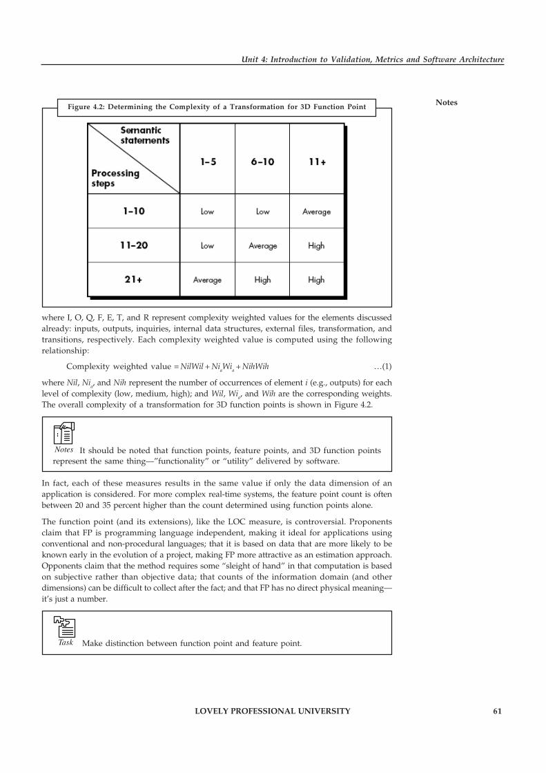
LOVELY PROFESSIONAL UNIVERSITY 61
Unit 4: Introduction to Validation, Metrics and Software Architecture
Notes
where I, O, Q, F, E, T, and R represent complexity weighted values for the elements discussedalready: inputs, outputs, inquiries, internal data structures, external files, transformation, andtransitions, respectively. Each complexity weighted value is computed using the followingrelationship:
Complexity weighted value = NilWil + NiaWia + NihWih …(1)
where Nil, Nia, and Nih represent the number of occurrences of element i (e.g., outputs) for eachlevel of complexity (low, medium, high); and Wil, Wia, and Wih are the corresponding weights.The overall complexity of a transformation for 3D function points is shown in Figure 4.2.
Notes It should be noted that function points, feature points, and 3D function pointsrepresent the same thing—”functionality” or “utility” delivered by software.
In fact, each of these measures results in the same value if only the data dimension of anapplication is considered. For more complex real-time systems, the feature point count is oftenbetween 20 and 35 percent higher than the count determined using function points alone.
The function point (and its extensions), like the LOC measure, is controversial. Proponentsclaim that FP is programming language independent, making it ideal for applications usingconventional and non-procedural languages; that it is based on data that are more likely to beknown early in the evolution of a project, making FP more attractive as an estimation approach.Opponents claim that the method requires some “sleight of hand” in that computation is basedon subjective rather than objective data; that counts of the information domain (and otherdimensions) can be difficult to collect after the fact; and that FP has no direct physical meaning—it’s just a number.
Task Make distinction between function point and feature point.
Figure 4.2: Determining the Complexity of a Transformation for 3D Function Point

62 LOVELY PROFESSIONAL UNIVERSITY
Principles of Software Engineering
Notes 4.2.2 Quality Metrics
Software metrics are numerical data related to software development. Metrics strongly supportsoftware project management activities. They relate to the four functions of management asfollows:
1. Planning: Metrics serve as a basis of cost estimating, training planning, resource planning,scheduling, and budgeting.
2. Organizing: Size and schedule metrics influence a project’s organization.
3. Controlling: Metrics are used to status and track software development activities forcompliance to plans.
4. Improving: Metrics are used as a tool for process improvement and to identify whereimprovement efforts should be concentrated and measure the effects of processimprovement efforts.
A metric quantifies a characteristic of a process or product. Metrics can be directly observablequantities or can be derived from one or more directly observable quantities.
Example: Raw metrics include the number of source lines of code, number ofdocumentation pages, number of staff-hours, number of tests, number of requirements, etc.
Example: Derived metrics include source lines of code per staff-hour, defects per thousandlines of code, or a cost performance index.
The term indicator is used to denote a representation of metric data that provides insight into anongoing software development project or process improvement activity. Indicators are metricsin a form suitable for assessing project behavior or process improvement.
Example: An indicator may be the behavior of a metric over time or the ratio of twometrics. Indicators may include the comparison of actual values versus the plan, project stabilitymetrics, or quality metrics.
Example: Indicators used on a project include actual versus planned task completions,actual versus planned staffing, number of trouble reports written and resolved over time, andnumber of requirements changes over time.
Indicators are used in conjunction with one another to provide a more complete picture ofproject or organization behavior.
Example: A progress indicator is related to requirements and size indicators.
All three indicators should be used and interpreted together.
Task Analyse the use of indicators in quality metrics.
An Overview of Factors that Affect Quality
McCall and Cavano define a set of quality factors that were a first step toward the developmentof metrics for software quality. These factors assess software from three distinct points of view:

LOVELY PROFESSIONAL UNIVERSITY 63
Unit 4: Introduction to Validation, Metrics and Software Architecture
Notes(1) product operation (using it), (2) product revision (changing it), and (3) product transition(modifying it to work in a different environment; i.e., “porting” it). In their work, the authorsdescribe the relationship between these quality factors (what they call a framework) and otheraspects of the software engineering process:
� First, the framework provides a mechanism for the project manager to identify whatqualities are important. These qualities are attributes of the software in addition to itsfunctional correctness and performance which have life cycle implications. Such factors asmaintainability and portability have been shown in recent years to have significant lifecycle cost impact . . .
� Secondly, the framework provides a means for quantitatively assessing how well thedevelopment is progressing relative to the quality goals established . . .
� Thirdly, the framework provides for more interaction of QA personnel throughout thedevelopment effort . . .
� Lastly, quality assurance personal can use indications of poor quality to help identify[better] standards to be enforced in the future.
Measuring Quality
Although there are many measures of software quality, correctness, maintainability, integrity,and usability provide useful indicators for the project team. Gilb suggests definitions andmeasures for each.
� Correctness: A program must operate correctly or it provides little value to its users.Correctness is the degree to which the software performs its required function. The mostcommon measure for correctness is defects per KLOC, where a defect is defined as averified lack of conformance to requirements. When considering the overall quality of asoftware product, defects are those problems reported by a user of the program after theprogram has been released for general use. For quality assessment purposes, defects arecounted over a standard period of time, typically one year.
� Maintainability: Software maintenance accounts for more effort than any other softwareengineering activity. Maintainability is the ease with which a program can be corrected ifan error is encountered, adapted if its environment changes, or enhanced if the customerdesires a change in requirements. There is no way to measure maintainability directly;therefore, we must use indirect measures. A simple time-oriented metric is mean-time-tochange (MTTC), the time it takes to analyze the change request, design an appropriatemodification, implement the change, test it, and distribute the change to all users. Onaverage, programs that are maintainable will have a lower MTTC (for equivalent types ofchanges) than programs that are not maintainable.
� Integrity: Software integrity has become increasingly important in the age of hackers andfirewalls. This attribute measures a system’s ability to withstand attacks (both accidentaland intentional) to its security. Attacks can be made on all three components of software:programs, data, and documents.
To measure integrity, two additional attributes must be defined: threat and security.Threat is the probability (which can be estimated or derived from empirical evidence) thatan attack of a specific type will occur within a given time. Security is the probability(which can be estimated or derived from empirical evidence) that the attack of a specifictype will be repelled. The integrity of a system can then be defined as:
Integrity = Summation [(1 – Threat) × (1 – Security)]
where threat and security are summed over each type of attack.

64 LOVELY PROFESSIONAL UNIVERSITY
Principles of Software Engineering
Notes � Usability: The catch phrase “user-friendliness” has become ubiquitous in discussions ofsoftware products. If a program is not user-friendly, it is often doomed to failure, even ifthe functions that it performs are valuable. Usability is an attempt to quantify user-friendliness and can be measured in terms of four characteristics: (1) the physical and orintellectual skill required to learn the system, (2) the time required to become moderatelyefficient in the use of the system, (3) the net increase in productivity (over the approachthat the system replaces) measured when the system is used by someone who is moderatelyefficient, and (4) a subjective assessment (sometimes obtained through a questionnaire) ofusers attitudes toward the system.
Defect Removal Efficiency
A quality metric that provides benefit at both the project and process level is Defect RemovalEfficiency (DRE). In essence, DRE is a measure of the filtering ability of quality assurance andcontrol activities as they are applied throughout all process framework activities.
When considered for a project as a whole, DRE is defined in the following manner:
DRE = E/(E + D) …(4.4)
where E is the number of errors found before delivery of the software to the end-user and D isthe number of defects found after delivery.
The ideal value for DRE is 1. That is, no defects are found in the software.
Did u know? Realistically, D will be greater than 0, but the value of DRE can still approach 1.
As E increases (for a given value of D), the overall value of DRE begins to approach 1. In fact, asE increases, it is likely that the final value of D will decrease (errors are filtered out before theybecome defects). If used as a metric that provides an indicator of the filtering ability of qualitycontrol and assurance activities, DRE encourages a software project team to institute techniquesfor finding as many errors as possible before delivery.
DRE can also be used within the project to assess a team’s ability to find errors before they arepassed to the next framework activity or software engineering task.
Example: The requirements analysis task produces an analysis model that can bereviewed to find and correct errors. Those errors that are not found during the review of theanalysis model are passed on to the design task (where they may or may not be found). Whenused in this context, we redefine DRE as
DREi = Ei/(Ei + Ei+1) …(4.5)
where Ei is the number of errors found during software engineering activity i and Ei+1 is thenumber of errors found during software engineering activity i+1 that are traceable to errors thatwere not discovered in software engineering activity i.
A quality objective for a software team (or an individual software engineer) is to achieve DREi
that approaches 1.
!Caution Errors should be filtered out before they are passed on to the next activity.

LOVELY PROFESSIONAL UNIVERSITY 65
Unit 4: Introduction to Validation, Metrics and Software Architecture
NotesSelf Assessment
Fill in the blanks:
6. Function-oriented software metrics use a measure of the functionality delivered by theapplication as a …………………… value.
7. …………………… are derived using an empirical relationship based on countable (direct)measures of software’s information domain and assessments of software complexity.
8. The …………………… measure accommodates applications in which algorithmiccomplexity is high.
9. …………………… are metrics in a form suitable for assessing project behavior or processimprovement.
10. A quality metric that provides benefit at both the project and process level…………………….
4.3 Software Architecture
When you discuss about the architecture of a building, many different attributes come to mind.At the most simplistic level, we consider the overall shape of the physical structure. But inreality, architecture is much more. It is the manner in which the various components of thebuilding are integrated to form a cohesive whole. It is the way in which the building fits into itsenvironment and meshes with other buildings in its vicinity. It is the degree to which thebuilding meets its stated purpose and satisfies the needs of its owner. It is the aesthetic feel of thestructure—the visual impact of the building and the way textures, colors, and materials arecombined to create the external facade and the internal “living environment.” It is small details—the design of lighting fixtures, the type of flooring, the placement of wall hangings, list is almostendless. And finally, it is art.
The software architecture of a program or computing system is the structure or structures of thesystem, which comprise software components, the externally visible properties of thosecomponents, and the relationships among them.
The architecture is not the operational software. Rather, it is a representation that enables asoftware engineer to (1) analyze the effectiveness of the design in meeting its stated requirements,(2) consider architectural alternatives at a stage when making design changes is still relativelyeasy, and (3) reducing the risks associated with the construction of the software.
This definition emphasizes the role of “software components” in any architectural representation.In the context of architectural design, a software component can be something as simple as aprogram module, but it can also be extended to include databases and “middleware” that enablethe configuration of a network of clients and servers. The properties of components are thosecharacteristics that are necessary to an understanding of how the components interact with othercomponents. At the architectural level, internal properties (e.g., details of an algorithm) are notspecified. The relationships between components can be as simple as a procedure call from onemodule to another or as complex as a database access protocol.
The main reasons that software architecture is important:
� Representations of software architecture are an enabler for communication between allparties (stakeholders) interested in the development of a computer-based system.
� The architecture highlights early design decisions that will have a profound impact on allsoftware engineering work that follows and, as important, on the ultimate success of thesystem as an operational entity.

66 LOVELY PROFESSIONAL UNIVERSITY
Principles of Software Engineering
Notes � Architecture “constitutes a relatively small, intellectually graspable model of how thesystem is structured and how its components work together”.
4.3.1 Architecture Views
There is a general view emerging that there is no unique architecture of a system. The definitionthat we have adopted (given above) also expresses this sentiment. Consequently, there is no onearchitecture drawing of the system. The situation is similar to that of civil construction, a disciplinethat is the original user of the concept of architecture and from where the concept of softwarearchitecture has been borrowed. For a building, if you want to see the floor plan, you are shownone set of drawings. If you are an electrical engineer and want to see how the electricitydistribution has been planned, you will be shown another set of drawings. And if you areinterested in safety and firefighting, another set of drawings is used. These drawings are notindependent of each other—they are all about the same building. However, each drawingprovides a different view of the building, a view that focuses on explaining one aspect of thebuilding and tries to a good job at that, while not divulging much about the other aspects. Andno one drawing can express all the different aspects—such a drawing will be too complex to beof any use.
Similar is the situation with software architecture. In software, the different drawings are calledviews. A view represents the system as composed of some types of elements and relationshipsbetween them. Which elements are used by a view, depends on what the view wants to highlight.Different views expose different properties and attributes, thereby allowing the stakeholdersand analysts to properly evaluate those attributes for the system. By focusing only on someaspects of the system, a view reduces the complexity that a reader has to deal with at a time,thereby aiding system understanding and analysis.
A view describes a structure of the system. We will use these two concepts—views and structures—interchangeably. We will also use the term architectural view to refer to a view. Many types ofviews have been proposed. Most of the proposed views generally belong to one of these threetypes:
1. Module
2. Component and connector
3. Allocation
In a module view, the system is viewed as a collection of code units, each implementing somepart of the system functionality. That is, the main elements in this view are modules. Theseviews are code-based and do not explicitly represent any runtime structure of the system.
Example: Modules are packages, a class, a procedure, a method, a collection of functions,and a collection of classes.
The relationships between these modules are also code-based and depend on how code of amodule interacts with another module.
Example: Relationships in this view are “is a part of” (i.e., module B is a part of moduleA), “uses or depends on” (a module A uses services of module B to perform its own functions andcorrectness of module A depends on correctness of module B), and “generalization orspecialization” (a module B is a generalization of a module A).
LOVELY PROFESSIONAL UNIVERSITY 67
Unit 4: Introduction to Validation, Metrics and Software Architecture
NotesIn a component and connector (C&C) view, the system is viewed as a collection of runtimeentities called components. That is, a component is a unit which has an identity in the executingsystem.
Example: Objects (not classes), a collection of objects, and a process are examples ofcomponents.
While executing, components need to interact with others to support the system services.Connectors provide means for this interaction.
Example: Connectors are pipes and sockets.
Shared data can also act as a connector. If the components use some middleware to communicateand coordinate, then the middleware is a connector. Hence, the primary elements of this vieware components and connectors.
An allocation view focuses on how the different software units are allocated to resources like thehardware, file systems, and people. That is, an allocation view specifies the relationship betweensoftware elements and elements of the environments in which the software system is executed.They expose structural properties like which processes run on which processor, and how thesystem files are organized on a file system.
An architecture description consists of views of different types, with each view exposing somestructure of the system. Module views show how the software is structured as a set ofimplementation units, C&C views show how the software is structured as interacting runtimeelements, and allocation views show how software relates to non-software structures. Thesethree types of view of the same system form the architecture of the system.
Note that the different views are not unrelated. They all represent the same system. Hence, thereare relationships between elements in one view and elements in another view. These relationshipsmay be simple or may be complex.
Example: The relationship between modules and components may be one to one in thatone module implements one component. On the other hand, it may be quite complex with amodule being used by multiple components, and a component using multiple modules.
While creating the different views, the designers have to be aware of this relationship.
The next question is what are the standard views that should be expressed for describing thearchitecture of a system? To answer this question, the analogy with buildings may again help. Ifone is building a simple small house, then perhaps there is no need to have a separate viewdescribing the emergency and the fire system. Similarly, if there is no air conditioning in thebuilding, there need not be any view for that. On the other hand, an office building will perhapsrequire both of these views, in addition to other views describing plumbing, space, wiring, etc.
However, despite the fact that there are multiple drawings showing different views of a building,there is one view that predominates in construction—that of physical structure. This view formsthe basis of other views in that other views cannot really be completed unless this view can bedone. Other views may or may not be needed for constructing a building, depending on thenature of the project. Hence, in a sense, the view giving the building structure may be consideredas the primary view in that it is almost always used, and other views rely on this viewsubstantially. The view also captures perhaps the most important property to be analyzed in theearly stages, namely, that of space organization.

68 LOVELY PROFESSIONAL UNIVERSITY
Principles of Software Engineering
Notes The situation with software architecture is also somewhat similar. As we have said, dependingon what properties are of interest, different views of the software architecture are needed.However, of these views, the C&C view has become the de facto primary view, one which isalmost always prepared when an architecture is designed (some definitions even viewarchitecture only in terms of C&C views). As partitioning a system into smaller parts andcomposing the system from these parts is also a goal of design, a natural question is what is thedifference between a design and architecture as both aim to achieve similar objectives and seemto fundamentally rely on the divide and conquer rule? First, it should be clear that architectureis a design in that it is in the solution domain and talks about the structure of the proposedsystem. Furthermore, an architecture view gives a high-level view of the system, relying onabstraction to convey the meaning—something which design also does. So, architecture is design.We can view architecture as a very high-level design, focusing only on main components, andthe architecture activity as the first step in design. What we term as design is really about themodules that will eventually exist as code. That is, they are a more concrete representation of theimplementation (though not yet an implementation). Consequently, during design lower-levelissues like the data structures, files, and sources of data, have to be addressed, while such issuesare not generally significant at the architecture level. We also take the view that design can beconsidered as providing the module view of the architecture of the system.
The boundaries between architecture and high-level design are not fully clear. The way the fieldhas evolved, we can say that the line between architecture and design is really up to the designeror the architect. At the architecture level, one needs to show only those parts that are needed toperform the desired evaluation. The internal structure of these parts is not important. On theother hand, during design, designing the structure of the parts that can lead to constructing themis one of the key tasks. However, which parts of the structure should be examined and revealedduring architecture and which parts during design is a matter of choice.
!Caution Details that are not needed to perform the types of analysis we wish to do at thearchitecture time are unnecessary and should be left for design to uncover.
4.3.2 Architectural Styles
When a builder uses the phrase “center hall colonial” to describe a house, most people familiarwith houses in the United States will be able to conjure a general image of what the house willlook like and what the floor plan is likely to be. The builder has used an architectural style as adescriptive mechanism to differentiate the house from other styles (e.g., A-frame, raised ranch,Cape Cod). But more important, the architectural style is also a pattern for construction. Furtherdetails of the house must be defined, its final dimensions must be specified, customized featuresmay be added, building materials are to be determined, but the pattern—a “center hall colonial”guides the builder in his work.
The software that is built for computer-based systems also exhibits one of many architecturalstyles. Each style describes a system category that encompasses (1) a set of components (e.g., adatabase, computational modules) that perform a function required by a system; (2) a set ofconnectors that enable “communication, coordination’s and cooperation” among components;(3) constraints that define how components can be integrated to form the system; and (4) semanticmodels that enable a designer to understand the overall properties of a system by analyzing theknown properties of its constituent parts.
Although millions of computer-based systems have been created over the past 50 years, the vastmajority can be categorized into one of a relatively small number of architectural styles:
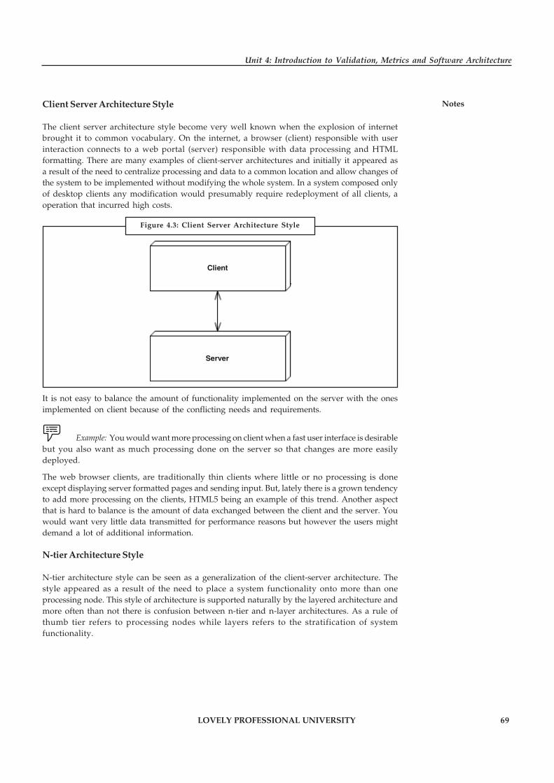
LOVELY PROFESSIONAL UNIVERSITY 69
Unit 4: Introduction to Validation, Metrics and Software Architecture
NotesClient Server Architecture Style
The client server architecture style become very well known when the explosion of internetbrought it to common vocabulary. On the internet, a browser (client) responsible with userinteraction connects to a web portal (server) responsible with data processing and HTMLformatting. There are many examples of client-server architectures and initially it appeared asa result of the need to centralize processing and data to a common location and allow changes ofthe system to be implemented without modifying the whole system. In a system composed onlyof desktop clients any modification would presumably require redeployment of all clients, aoperation that incurred high costs.
Client
Server
It is not easy to balance the amount of functionality implemented on the server with the onesimplemented on client because of the conflicting needs and requirements.
Example: You would want more processing on client when a fast user interface is desirablebut you also want as much processing done on the server so that changes are more easilydeployed.
The web browser clients, are traditionally thin clients where little or no processing is doneexcept displaying server formatted pages and sending input. But, lately there is a grown tendencyto add more processing on the clients, HTML5 being an example of this trend. Another aspectthat is hard to balance is the amount of data exchanged between the client and the server. Youwould want very little data transmitted for performance reasons but however the users mightdemand a lot of additional information.
N-tier Architecture Style
N-tier architecture style can be seen as a generalization of the client-server architecture. Thestyle appeared as a result of the need to place a system functionality onto more than oneprocessing node. This style of architecture is supported naturally by the layered architecture andmore often than not there is confusion between n-tier and n-layer architectures. As a rule ofthumb tier refers to processing nodes while layers refers to the stratification of systemfunctionality.
Figure 4.3: Client Server Architecture Style

70 LOVELY PROFESSIONAL UNIVERSITY
Principles of Software Engineering
NotesExample: Figure 4.4 is a classical example of a n-tier architecture:
Dabase Server
Web Browser
Web Server
As with layered architecture you need to make a decision regarding the number of tiers balancingthe performance, separation of concerns, deployment complexity, hardware, etc.
Shared Data Style
The high level design solution is based on a shared data-store which acts as the “central command”with 2 variations:
� Blackboard Style: the data-store alerts the participating parties whenever there is a data-store change (trigger)
� Repository Style: the participating parties check the data-store for changes
Problems that fit this style such as patient processing, tax processing system, inventory controlsystem; etc. have the following properties:
1. All the functionalities work off a single data-store.
2. Any change to the data-store may affect all or some of the functions
3. All the functionalities need the information from the data-store
Figure 4.4: N-tier Architecture Style Example
Figure 4.5: Example of Shared Data Style

LOVELY PROFESSIONAL UNIVERSITY 71
Unit 4: Introduction to Validation, Metrics and Software Architecture
NotesIn database management system we can set up a trigger which has 3 parts:
1. Event: change to the database that alerts or activates the trigger
2. Condition: a test that is true when the trigger is activated
3. Action: a procedure which is executed when the trigger is activated and the condition istrue.
A trigger may be thought as a monitor of the database for changes to the database that matchesthe event specification (e.g. debit of bank customer accountant). Then the condition is checked tosee if it is true (e.g. debited cust account results in negative bank accnt amount). If the debitedaccount has a negative accnt amount, then kick off a procedure to send error message out anddelay the execution of cust account debiting.
Advantages of shared data are:
� The independent functions are cohesive within itself and the coupling is restricted to theshared data
� Single data-store makes the maintenance of data in terms of back-up recovery and securityeasier to manage
Disadvantages of shared data are:
� (Common and control coupling through data) Any data format change in the shared datarequires agreement and, potentially, changes in all or some the functional areas – thisbecomes a bigger problem as more functionalities are introduced that have dependencyon the shared data (e.g. popular commercial product such as CRM or ERP)
� If the data-store fails, all parties are affected and possibly all functions have to stop (mayneed to have (1) redundant db for this architecture style; also, should have (2) good backup - and recovery procedures.)
Task Compare and contrast Blackboard style and repository style.
Call and Return Architectures
This architectural style enables a software designer (system architect) to achieve a programstructure that is relatively easy to modify and scale. A number of substyles exist within thiscategory:
� Main Program/subprogram Architectures: This classic program structure decomposesfunction into a control hierarchy where a “main” program invokes a number of programcomponents, which in turn may invoke still other components. Figure 4.6 illustratesarchitecture of this type.
� Remote Procedure Call Architectures: The components of a main program/subprogramarchitecture are distributed across multiple computers on a network.
Object-oriented Architectures
The components of a system encapsulate data and the operations that must be applied tomanipulate the data. Communication and coordination between components is accomplishedvia message passing.

72 LOVELY PROFESSIONAL UNIVERSITY
Principles of Software Engineering
Notes
Layered Architectures
The basic structure of a layered architecture is illustrated in Figure 4.7. A number of differentlayers are defined, each accomplishing operations that progressively become closer to the machineinstruction set. At the outer layer, components service user interface operations. At the innerlayer, components perform operating system interfacing. Intermediate layers provide utilityservices and application software functions.
Self Assessment
Fill in the blanks:
11. At the architectural level, …………………… properties are not specified.
Figure 4.6: Structure Terminology for a Call and Return Architectural Style
Figure 4.7: Layered Architecture

LOVELY PROFESSIONAL UNIVERSITY 73
Unit 4: Introduction to Validation, Metrics and Software Architecture
Notes12. A …………………… represents the system as composed of some types of elements andrelationships between them.
13. In a …………………… view, the system is viewed as a collection of code units, eachimplementing some part of the system functionality.
14. A …………………… is a unit which has an identity in the executing system.
15. An …………………… view focuses on how the different software units are allocated toresources like the hardware, file systems, and people.
�Case Study Measuring Software Quality
The National Security Agency’s mission is to provide support for the security of theUnited States. Over the years, the Agency has become extremely dependent on thesoftware that makes up its information technology infrastructure. NSA has come to
view software as a critical resource upon which much of the world’s security, prosperity,and economic competitiveness increasingly rests. If anything, dependence on softwareand its corresponding effect on national security makes it imperative for NSA to acceptand maintain only the highest quality software. Cost overruns, or software systems thatare defective or of low quality, can impose a significant burden on national security andNSA’s mission.
Software Engineering Applied Technology Center
The NSA organization responsible for addressing these needs is the Software EngineeringApplied Technology Center. The SEATC’s goal is to reduce maintenance costs whileimproving software development. In addition, NSA has formed partnerships with othergovernment agencies and industry consortiums, the Software Engineering Institute, andvendors who supply automated tools and support technology for software development.Its aim is to discover the best current practices in government and industry and bringknowledge of them to NSA organizations.
A key initiative addresses software quality engineering. The benefits of structured testingand quality assurance activities throughout the entire software life cycle are oftenoverlooked, but they are a key part of a complete software engineering process. Testingactivities provide key software metrics and feedback mechanisms for defining andimproving software products across a broad spectrum of software development activitiesat NSA. Process-level activities involve technical test management support and softwarequality assurance program implementation. After nearly three years of measurement andquality assurance activities, the SEATC has collected and analyzed the results on some 25million lines of C, C++, Fortran, and Ada code. We have developed a streamlined set ofcode-level release criteria that we apply to code written at NSA organizations. This 25million lines of code is the sample drawn from a population of more than one billion linesof code at NSA. The result is a highly correlated set of measures that promote high-qualityprocesses where they matter most¾ at the code level.
The SEATC Software Quality Measures
We use two primary measurement activities to derive our code-level release criteria. Thefirst is code metrics analysis: We measure development productivity indicators,predictability measures, maintainability indicators, essential quality attributes of the code,and “hot spots,” and we identify overly complex modules that need additional work.
Contd...
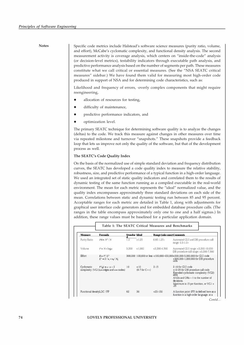
74 LOVELY PROFESSIONAL UNIVERSITY
Principles of Software Engineering
Notes Specific code metrics include Halstead’s software science measures (purity ratio, volume,and effort), McCabe’s cyclomatic complexity, and functional density analysis. The secondmeasurement activity is coverage analysis, which centers on “inside-the-code” analysis(or decision-level metrics), testability indicators through executable path analysis, andpredictive performance analysis based on the number of segments per path. These measuresconstitute what we call critical or essential measures. (See the “NSA SEATC criticalmeasures” sidebar.) We have found them valid for measuring most high-order codeproduced in support of NSA and for determining code characteristics, such as:
Likelihood and frequency of errors, ·overly complex components that might requirereengineering,
� allocation of resources for testing,
� difficulty of maintenance,
� predictive performance indicators, and
� optimization level.
The primary SEATC technique for determining software quality is to analyze the changes(deltas) to the code. We track this measure against changes in other measures over timevia repeated milestone and turnover “snapshots.” These snapshots provide a feedbackloop that lets us improve not only the quality of the software, but that of the developmentprocess as well.
The SEATC’s Code Quality Index
On the basis of the normalized use of simple standard deviation and frequency distributioncurves, the SEATC has developed a code quality index to measure the relative stability,robustness, size, and predictive performance of a typical function in a high-order language.We used an integrated set of static quality indicators and correlated them to the results ofdynamic testing of the same function running as a compiled executable in the real-worldenvironment. The mean for each metric represents the “ideal” normalized value, and thequality index encompasses approximately three standard deviations on each side of themean. Correlations between static and dynamic testing run between 85 and 95 percent.Acceptable ranges for each metric are detailed in Table 1, along with adjustments forgraphical user interface code generators and for embedded database procedure calls. (Theranges in the table encompass approximately only one to one and a half sigmas.) Inaddition, these range values must be baselined for a particular application domain.
Table 1: The SEATC Critical Measures and Benchmarks
Contd...
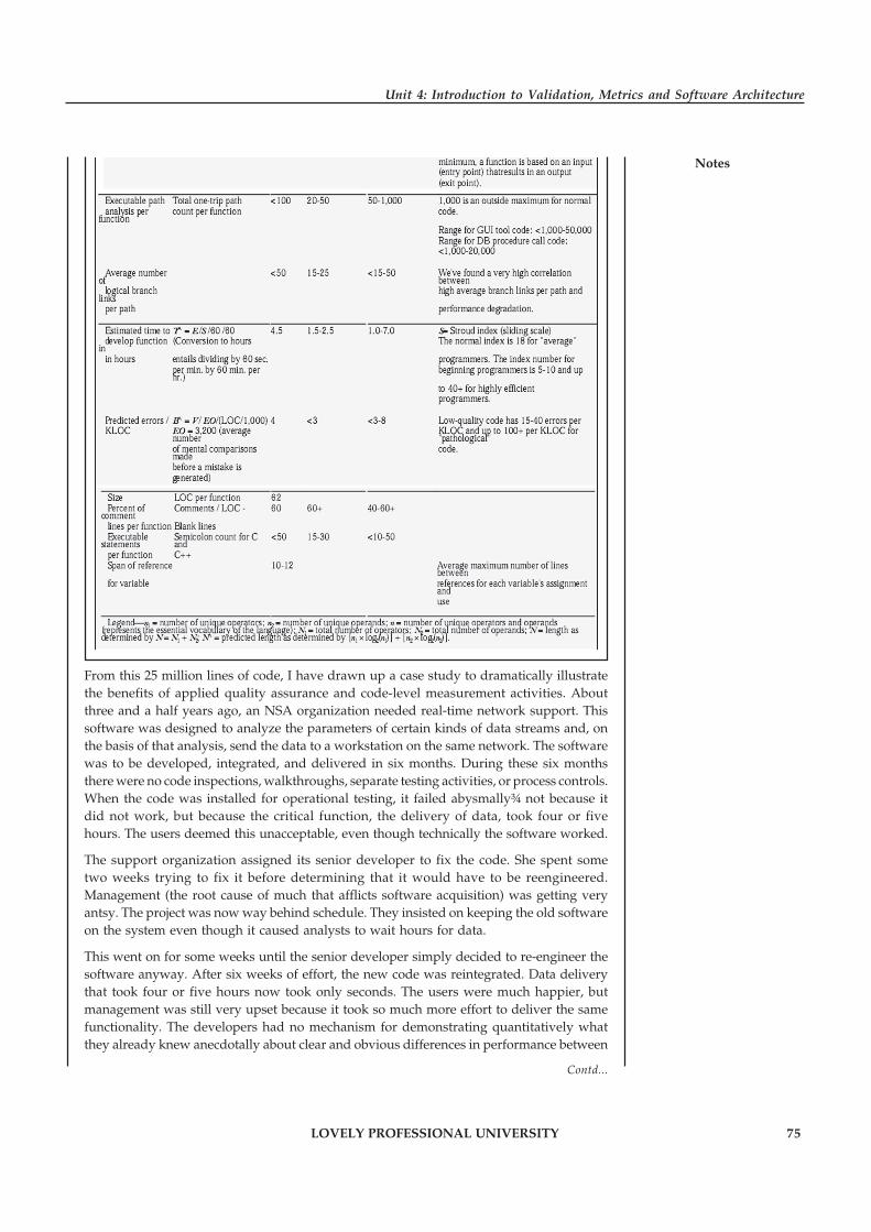
LOVELY PROFESSIONAL UNIVERSITY 75
Unit 4: Introduction to Validation, Metrics and Software Architecture
Notes
From this 25 million lines of code, I have drawn up a case study to dramatically illustratethe benefits of applied quality assurance and code-level measurement activities. Aboutthree and a half years ago, an NSA organization needed real-time network support. Thissoftware was designed to analyze the parameters of certain kinds of data streams and, onthe basis of that analysis, send the data to a workstation on the same network. The softwarewas to be developed, integrated, and delivered in six months. During these six monthsthere were no code inspections, walkthroughs, separate testing activities, or process controls.When the code was installed for operational testing, it failed abysmally¾ not because itdid not work, but because the critical function, the delivery of data, took four or fivehours. The users deemed this unacceptable, even though technically the software worked.
The support organization assigned its senior developer to fix the code. She spent sometwo weeks trying to fix it before determining that it would have to be reengineered.Management (the root cause of much that afflicts software acquisition) was getting veryantsy. The project was now way behind schedule. They insisted on keeping the old softwareon the system even though it caused analysts to wait hours for data.
This went on for some weeks until the senior developer simply decided to re-engineer thesoftware anyway. After six weeks of effort, the new code was reintegrated. Data deliverythat took four or five hours now took only seconds. The users were much happier, butmanagement was still very upset because it took so much more effort to deliver the samefunctionality. The developers had no mechanism for demonstrating quantitatively whatthey already knew anecdotally about clear and obvious differences in performance between
Contd...
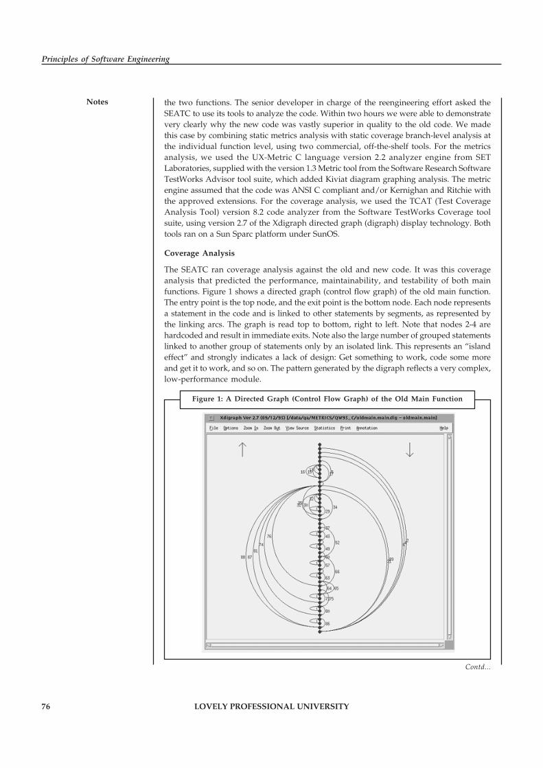
76 LOVELY PROFESSIONAL UNIVERSITY
Principles of Software Engineering
Notes the two functions. The senior developer in charge of the reengineering effort asked theSEATC to use its tools to analyze the code. Within two hours we were able to demonstratevery clearly why the new code was vastly superior in quality to the old code. We madethis case by combining static metrics analysis with static coverage branch-level analysis atthe individual function level, using two commercial, off-the-shelf tools. For the metricsanalysis, we used the UX-Metric C language version 2.2 analyzer engine from SETLaboratories, supplied with the version 1.3 Metric tool from the Software Research SoftwareTestWorks Advisor tool suite, which added Kiviat diagram graphing analysis. The metricengine assumed that the code was ANSI C compliant and/or Kernighan and Ritchie withthe approved extensions. For the coverage analysis, we used the TCAT (Test CoverageAnalysis Tool) version 8.2 code analyzer from the Software TestWorks Coverage toolsuite, using version 2.7 of the Xdigraph directed graph (digraph) display technology. Bothtools ran on a Sun Sparc platform under SunOS.
Coverage Analysis
The SEATC ran coverage analysis against the old and new code. It was this coverageanalysis that predicted the performance, maintainability, and testability of both mainfunctions. Figure 1 shows a directed graph (control flow graph) of the old main function.The entry point is the top node, and the exit point is the bottom node. Each node representsa statement in the code and is linked to other statements by segments, as represented bythe linking arcs. The graph is read top to bottom, right to left. Note that nodes 2-4 arehardcoded and result in immediate exits. Note also the large number of grouped statementslinked to another group of statements only by an isolated link. This represents an “islandeffect” and strongly indicates a lack of design: Get something to work, code some moreand get it to work, and so on. The pattern generated by the digraph reflects a very complex,low-performance module.
Contd...
Figure 1: A Directed Graph (Control Flow Graph) of the Old Main Function

LOVELY PROFESSIONAL UNIVERSITY 77
Unit 4: Introduction to Validation, Metrics and Software Architecture
NotesEach node represents a statement in the code and is linked to other statements by segments,as represented by the linking arcs. The pattern generated by the digraph reflects a verycomplex, low-performance module. This is by no means the total number. The originalanalysis on oldmain.c was executed on a Sparcstation 2 running 32 Mbytes of RAM and 32Mbytes of swap space. After half an hour it ran out of memory after reporting at least160,000 one-trip executable paths. When we put it on a Sparcstation 20 with 64 Mbytes ofRAM and allocated 2.1 Gbytes of swap space from the network, it ran out of memory afteralmost 2.5 hours and reported more than eight million one-trip executable paths.
The normal maximum number of executable paths per function is 100. The extreme outsidemaximum is 1,000. The ideal number of paths is 20-50 on average per function. From atestability perspective, this particular function with its more than eight million pathscannot be tested. From a maintenance perspective, the program is essentiallyunmaintainable. Predicting a module’s performance is also important.
Software Risk Management
As a result of this kind of analysis, the SEATC is now promoting a series of measuresrelated to defect rates, code/system scrap rates, workflow and process measures, and costmeasures related to cost-per-unit of code based on level-of-effort calculations, maintenanceresource analysis, and productivity measures. The whole intent of NSA’s software qualityprogram is to reduce risk by managing it through the analysis of measurement dataapplied to both process and development tasks down to the functional code. NSA isinvesting in the long-term software process and programming environments to ensurethe long-term stability and operational use of its software base. The national securitystakes are just too great. The NSA SEATC created a comprehensive software processimprovement effort through a series of strategic partnerships and pilot programs thatallow the establishment, measurement, formalization, and improvement of the full lifecycle software process.
The SEATC uses the SEI Capability Maturity Model as the basis for this initiative.In addition, we use the Experience Factory developed by NASA’s Software EngineeringLaboratory as the mechanism for evaluating software improvement initiatives. TheExperience Factory model allows NSA to gather objective measurements for softwaredevelopment organizations and analyze them to determine the effectiveness ofdevelopment techniques and document their costs and associated level of effort.Reengineering, reuse, integrated software development environments, object-orientedtechnology, and training are additional SEATC initiatives to promote and sustainhigh-quality software.
Conclusion
Many people talk about market share and software content, but not in a tangible way. Aproject needs real measures from real data. If we don’t really understand softwareproductivity factors, then we won’t know how to improve our development processes.None of the current or proposed software quality and process “standards” enforce thedetails of the software development process, so a real software process must be built fromwithin. But change, even when done for the right reasons, will upset the status quo andwill upset established norms and behavior patterns. More importantly, it will upset theminds and perceptions of people.
We must recognize the importance of the people in the process. Improved quality andhigher productivity can be achieved by tapping their inherent strengths. The appropriateuse of metrics and statistical techniques can help us measure progress and provide supportto our software development teams, while at the same time mitigating risk, lowering
Contd...

78 LOVELY PROFESSIONAL UNIVERSITY
Principles of Software Engineering
Notes cost, and improving quality. Proceed with deliberate intent and create meaningful goalsbased on the benchmarking of key development processes and milestones. Your code willbe happier for it.
Questions:
1. Discuss the SEATC technique for determining software quality.
2. Explain coverage analysis in the above case.
Source: http://mridulasharma.com/wp-content/uploads/2013/01/Assignment-G-3.pdf
4.4 Summary
� The basic objective of the requirements validation activity is to ensure that the SRS reflectsthe actual requirements accurately and clearly.
� A software metric relates the individual measures in some way (e.g., the average numberof errors found per review or the average number of errors found per person-hour expendedon reviews).
� Product metrics quantitatively characterize some aspect of the structure of a softwareproduct, such as a requirements specification, a design, or source code. They are alsocommonly.
� Function-oriented software metrics use a measure of the functionality delivered by theapplication as a normalization value.
� A function point extension called feature points is a superset of the function point measurethat can be applied to systems and engineering software applications.
� The Boeing approach integrates the data dimension of software with the functional andcontrol dimensions to provide a function-oriented measure amenable to applications thatemphasize function and control capabilities.
� Software metrics are numerical data related to software development.
� A quality metric that provides benefit at both the project and process level is DefectRemoval Efficiency (DRE).
� A view represents the system as composed of some types of elements and relationshipsbetween them.
� The builder has used an architectural style as a descriptive mechanism to differentiate thehouse from other styles.
� A component is a unit which has an identity in the executing system.
4.5 Keywords
Boeing Approach: The Boeing approach integrates the data dimension of software with thefunctional and control dimensions to provide a function-oriented measure amenable toapplications that emphasize function and control capabilities.
DRE: A quality metric that provides benefit at both the project and process level is DefectRemoval Efficiency (DRE).
Function Points: Function points are derived using an empirical relationship based on countable(direct) measures of software’s information domain and assessments of software complexity.
LOVELY PROFESSIONAL UNIVERSITY 79
Unit 4: Introduction to Validation, Metrics and Software Architecture
NotesIndicator: The term indicator is used to denote a representation of metric data that providesinsight into an ongoing software development project or process improvement activity.
Product Metrics: Product metrics quantitatively characterize some aspect of the structure of asoftware product, such as a requirements specification, a design, or source code.
Software Metrics: Software metrics are numerical data related to software development.
State: A state represents some externally observable mode of behavior, and a transition occursas a result of some event.
View: A view represents the system as composed of some types of elements and relationshipsbetween them.
4.6 Review Questions
1. Discuss the concept of validation in software engineering.
2. What is the purpose of software metrics? Discuss.
3. Explain the concept of Function-oriented software metrics.
4. Discuss the process of computing function points.
5. Function points, feature points, and 3D function points represent the same thing. Comment.
6. Discuss the functions of management related to quality metrics.
7. Discuss the quality factors towards the development of metrics for software quality.
8. Explain the concept of Defect Removal Efficiency (DRE).
9. What are architectural views? Also discuss the different types of views.
10. Explain the concept of client/server architectural style and shared data architectural style.
Answers: Self Assessment
1. validation 2. Metrics
3. product 4. External
5. complexity metrics 6. Normalization
7. Function points 8. feature point
9. Indicators 10. is Defect Removal Efficiency (DRE)
11. internal 12. View
13. module 14. Component
15. allocation
4.7 Further Readings
Books Rajib Mall, Fundamentals of Software Engineering, 2nd Edition, PHI.
Richard Fairpy, Software Engineering Concepts, Tata McGraw Hill, 1997.
80 LOVELY PROFESSIONAL UNIVERSITY
Principles of Software Engineering
Notes R.S. Pressman, Software Engineering – A Practitioner’s Approach, 5th Edition, TataMcGraw Hill Higher education.
Sommerville, Software Engineering, 6th Edition, Pearson Education
Online links http://www.chambers.com.au/glossary/verification_validation.php
http://www.inf.ed.ac.uk/teaching/courses/cs2/LectureNotes/CS2Ah/SoftEng/se08.pdf
http://www.cs.colorado.edu/~kena/classes/5828/s12/presentation-materials/boughtonalexandra.pdf
http://web.itu.edu.tr/gokmen/SE-lecture-2.pdf
LOVELY PROFESSIONAL UNIVERSITY 81
Unit 5: Software Project Planning
NotesUnit 5: Software Project Planning
CONTENTS
Objectives
Introduction
5.1 Process Planning
5.2 Effort Estimation
5.2.1 Factors Contributing to Inaccurate Estimation
5.2.2 Impact of Under-estimating
5.2.3 The Estimation Process
5.3 The COCOMO Model
5.3.1 Brief Characteristics of the Model
5.3.2 Levels
5.3.3 Appraisal of the Model
5.3.4 Modes
5.4 Project Scheduling and Staffing
5.4.1 Comments on “Lateness”
5.4.2 Basic Principles
5.4.3 Project Staffing
5.5 Introduction to Software Configuration Management
5.5.1 Baselines
5.5.2 Software Configuration Items
5.5.3 The SCM Process
5.5.4 Identification of Objects in the Software Configuration
5.6 Quality Plan
5.7 Risk Management
5.7.1 Software Risk Management
5.7.2 Risk Classification
5.7.3 Strategies for Risk Management
5.8 Project Monitoring
5.8.1 Time Sheets
5.8.2 Reviews
5.8.3 Cost-Schedule-Milestone Graph
5.8.4 Earned Value Method
5.9 Summary
5.10 Keywords
5.11 Review Questions
5.12 Further Readings
82 LOVELY PROFESSIONAL UNIVERSITY
Principles of Software Engineering
Notes Objectives
After studying this unit, you will be able to:
� Discuss the concept of process planning and effort estimation
� Explain the concept of COCOMO model
� Describe project scheduling and staffing
� Explain software configuration management
� Discuss risk management and project monitoring
Introduction
Project planning is a common thread that intertwines all the activities from conception tocommissioning and handing over the clockwork to clients. Project planning encompasses theessential activities such as work breakdown structure, statement of work, and accurate timeestimates and schedules which help further in anticipating snags in a project and overcomethem. A plan is the first step in providing the means to satisfy the needs of a project sponsor andhelp in paving the way to reach desired goal. It is a beginning of the project manager’s input toensure that potential problems are identified timely and can easily be assessed on the basis ofwhich further estimating and resource allocation may be comfortably done. That means,prevention is better than cure’ philosophy is adhered to while drafting the project plans. SoftwareConfiguration Management (SCM) is one of the foundations of software engineering. It is usedto track and manage the emerging product and its versions.
5.1 Process Planning
Project Planning is an aspect of Project Management that focuses a lot on Project Integration. Theproject plan reflects the current status of all project activities and is used to monitor and controlthe project. The Project Planning tasks ensure that various elements of the Project are coordinatedand therefore guide the project execution.
Project Planning helps in:
� Facilitating communication
� Monitoring/measuring the project progress
� Provides overall documentation of assumptions/planning decisions
The Project Planning Phases can be broadly classified as follows:
� Development of the Project Plan
� Execution of the Project Plan
� Change Control and Corrective Actions
Project Planning is an ongoing effort throughout the Project Lifecycle.
Project planning is crucial to the success of the Project.
!Caution Careful planning right from the beginning of the project can help to avoid costlymistakes.

LOVELY PROFESSIONAL UNIVERSITY 83
Unit 5: Software Project Planning
NotesIt provides an assurance that the project execution will accomplish its goals on schedule andwithin budget.
Project Planning spans across the various aspects of the Project. Generally Project Planning isconsidered to be a process of estimating, scheduling and assigning the projects resources inorder to deliver an end product of suitable quality. However it is much more as it can assume avery strategic role, which can determine the very success of the project. A Project Plan is one ofthe crucial steps in Project Planning in General!
Typically Project Planning can include the following types of project Planning:
1. Project Scope Definition and Scope Planning
2. Project Activity Definition and Activity Sequencing
3. Time, Effort and Resource Estimation
4. Risk Factors Identification
5. Cost Estimation and Budgeting
6. Organizational and Resource Planning
7. Schedule Development
8. Quality Planning
9. Risk Management Planning
10. Project Plan Development and Execution
11. Performance Reporting
12. Planning Change Management
13. Project Rollout Planning
We now briefly examine each of the above steps:
1. Project Scope Definition and Scope Planning: In this step we document the project workthat would help us achieve the project goal. We document the assumptions, constraints,user expectations, Business Requirements, Technical requirements, project deliverables,project objectives and everything that defines the final product requirements. This is thefoundation for a successful project completion.
2. Quality Planning: The relevant quality standards are determined for the project. This isan important aspect of Project Planning. Based on the inputs captured in the previous stepssuch as the Project Scope, Requirements, deliverables, etc. various factors influencing thequality of the final product are determined. The processes required to deliver the Productas promised and as per the standards are defined.
3. Project Activity Definition and Activity Sequencing: In this step we define all the specificactivities that must be performed to deliver the product by producing the various productdeliverables. The Project Activity sequencing identifies the interdependence of all theactivities defined.
4. Time, Effort and Resource Estimation: Once the Scope, Activities and Activityinterdependence is clearly defined and documented, the next crucial step is to determinethe effort required to complete each of the activities. The Effort can be calculated using oneof the many techniques available such as Function Points, Lines of Code, Complexity ofCode, Benchmarks, etc.
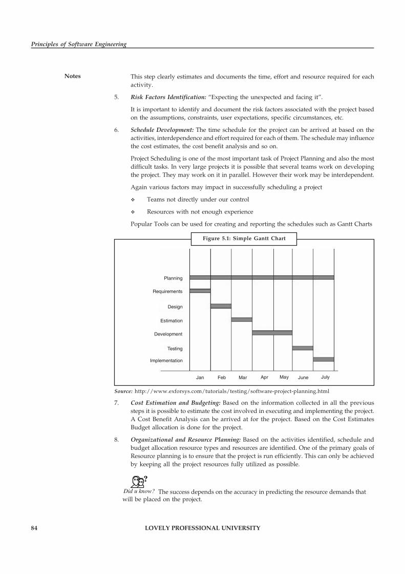
84 LOVELY PROFESSIONAL UNIVERSITY
Principles of Software Engineering
Notes This step clearly estimates and documents the time, effort and resource required for eachactivity.
5. Risk Factors Identification: “Expecting the unexpected and facing it”.
It is important to identify and document the risk factors associated with the project basedon the assumptions, constraints, user expectations, specific circumstances, etc.
6. Schedule Development: The time schedule for the project can be arrived at based on theactivities, interdependence and effort required for each of them. The schedule may influencethe cost estimates, the cost benefit analysis and so on.
Project Scheduling is one of the most important task of Project Planning and also the mostdifficult tasks. In very large projects it is possible that several teams work on developingthe project. They may work on it in parallel. However their work may be interdependent.
Again various factors may impact in successfully scheduling a project
� Teams not directly under our control
� Resources with not enough experience
Popular Tools can be used for creating and reporting the schedules such as Gantt Charts
Planning
Requirements
Design
Estimation
Development
Testing
Implementation
Jan Feb Mar Apr May June July
Source: http://www.exforsys.com/tutorials/testing/software-project-planning.html
7. Cost Estimation and Budgeting: Based on the information collected in all the previoussteps it is possible to estimate the cost involved in executing and implementing the project.A Cost Benefit Analysis can be arrived at for the project. Based on the Cost EstimatesBudget allocation is done for the project.
8. Organizational and Resource Planning: Based on the activities identified, schedule andbudget allocation resource types and resources are identified. One of the primary goals ofResource planning is to ensure that the project is run efficiently. This can only be achievedby keeping all the project resources fully utilized as possible.
Did u know? The success depends on the accuracy in predicting the resource demands thatwill be placed on the project.
Figure 5.1: Simple Gantt Chart
LOVELY PROFESSIONAL UNIVERSITY 85
Unit 5: Software Project Planning
NotesResource planning is an iterative process and necessary to optimize the use of resourcesthroughout the project life cycle thus making the project execution more efficient. Thereare various types of resources – Equipment, Personnel, Facilities, Money, etc.
9. Risk Management Planning: Risk Management is a process of identifying, analyzing andresponding to a risk. Based on the Risk factors Identified a Risk resolution Plan is created.The plan analyses each of the risk factors and their impact on the project. The possibleresponses for each of them can be planned. Throughout the lifetime of the project theserisk factors are monitored and acted upon as necessary.
10. Project Plan Development and Execution: Project Plan Development uses the inputs gatheredfrom all the other planning processes such as Scope definition, Activity identification,Activity sequencing, Quality Management Planning, etc. A detailed Work Break downstructure comprising of all the activities identified is used. The tasks are scheduled basedon the inputs captured in the steps previously described. The Project Plan documents allthe assumptions, activities, schedule, timelines and drives the project.
Each of the Project tasks and activities are periodically monitored. The team and thestakeholders are informed of the progress. This serves as an excellent communicationmechanism. Any delays are analyzed and the project plan may be adjusted accordingly
11. Performance Reporting: As described above the progress of each of the tasks/activitiesdescribed in the Project plan is monitored. The progress is compared with the scheduleand timelines documented in the Project Plan. Various techniques are used to measure andreport the project performance such as EVM (Earned Value Management) A wide varietyof tools can be used to report the performance of the project such as PERT Charts, GANTTcharts, Logical Bar Charts, Histograms, Pie Charts, etc.
12. Planning Change Management: Analysis of project performance can necessitate that certainaspects of the project be changed. The Requests for Changes need to be analyzed carefullyand its impact on the project should be studied. Considering all these aspects the ProjectPlan may be modified to accommodate this request for Change.
Change Management is also necessary to accommodate the implementation of the projectcurrently under development in the production environment. When the new product isimplemented in the production environment it should not negatively impact theenvironment or the performance of other applications sharing the same hostingenvironment.
13. Project Rollout Planning: In Enterprise environments, the success of the Project dependsa great deal on the success of its rollout and implementations. Whenever a Project is rolledout it may affect the technical systems, business systems and sometimes even the waybusiness is run. For an application to be successfully implemented not only the technicalenvironment should be ready but the users should accept it and use it effectively. For thisto happen the users may need to be trained on the new system. All this requires planning.
Self Assessment
Fill in the blanks:
1. The …………………… tasks ensure that various elements of the Project are coordinatedand therefore guide the project execution.
2. …………………… is an iterative process and necessary to optimize the use of resourcesthroughout the project life cycle.
86 LOVELY PROFESSIONAL UNIVERSITY
Principles of Software Engineering
Notes 5.2 Effort Estimation
Software Cost Estimation is widely considered to be a weak link in software project management.It requires a significant amount of effort to perform it correctly. Errors in Software Cost Estimationcan be attributed to a variety of factors. Various studies in the last decade indicated that 3 out of4 Software projects are not finished on time or within budget or both.
The group of people responsible for creating a software cost estimate can vary with eachorganization. However the following is possible in most scenarios.
People who are directly involved with the implementation are involved in the estimate.
� Project Manager is responsible for producing realistic cost estimates.
� Project Managers may perform this task on their own or consult with programmersresponsible.
Various studies indicate that if the programmers responsible for development are involved inthe estimation it was more accurate. The programmers have more motivation to meet thetargets if they were involved in the estimation process.
Following scenarios are also possible:
� An independent cost estimation team creates an Estimate.
� Independent Experts are given the Software specification and they create a Software Costestimate. The Estimation team reviews this and group consensus arrives at a final figure.
5.2.1 Factors Contributing to Inaccurate Estimation
The factors contributing to inaccurate estimation are as follows:
� Scope Creeps, imprecise and drifting requirements.
� New software projects pose new challenges, which may be very different from the pastprojects.
� Many teams fail to document metrics and lessons learned from past projects.
� Many a times the estimates are forced to match the available time and resources byaggressive leaders.
� Unrealistic estimates may be created by various ‘political under currents’.
5.2.2 Impact of Under-estimating
Under-estimating a project can be vary damaging:
� It leads to improper Project Planning
� It can also result in under-staffing and may result in an over worked and burnt out team
� Above all the quality of deliverables may be directly affected due insufficient testing andQA
� Missed Dead lines cause loss of Credibility and goodwill
5.2.3 The Estimation Process
Generally the Software Cost estimation process comprises of 4 main steps:
1. Estimate the size of the development product: This comprises of various sub-steps or subtasks. These tasks may have been done already during Requirement Analysis phase. If not

LOVELY PROFESSIONAL UNIVERSITY 87
Unit 5: Software Project Planning
Notesthen they should be done as a part of the estimation Process. Important thing is that theyshould be done to ensure the success of the Estimation Process and the Software Project asa whole.
� Create a detailed Work Break Down Structure. This directly impacts the accuracy ofthe estimate. This is one of the most important steps. The Work Break down structureshould include any and all tasks that are within the scope of the Project, which isbeing estimated. The most serious handicap is the inability to clearly visualize thesteps involved in the Project. Executing a Software Project is not just coding.
� The work Break down structure will include the size and complexity of each softwaremodule that can be expressed as number of Lines of Code, Function Points, or anyother unit of measure.
� The Work Break down structure should include tasks other than coding such asSoftware Configuration Management, various levels and types of Testing,Documentation, Communication, User Interaction, Implementation, KnowledgeTransition, Support tasks (if any) and so on.
� Clearly indicate or eliminate any gray areas (vague/unclear specifications etc.).
� Also take into account the various Risk Factors and down times. There are manydifferent Risk Factors involved – Technical aspects such as availability of theEnvironment, Server/Machine uptime, 3rd party Software Hardware failures orHuman aspects – Employee Attrition, Sick time, etc. Some of them may seem to be‘overkill’ but real world experience shows that these factors affect the time lines ofa project. If ignored they may adversely impact the Project timelines and estimates.
2. Estimate the effort in Person-hours: The Result of various tasks involved in step 1 is aneffort estimate in person hours. The effort of various Project tasks expressed in person-hours is also influenced by various factors such as:
� Experience/Capability of the Team members
� Technical resources
� Familiarity with the Development Tools and Technology Platform
3. Estimate the Schedule in Calendar Months: The Project Planners work closely with theTechnical Leads, Project Manager and other stakeholders and create a Project schedule.Tight Schedules may impact the Cost needed to develop the Application.
4. Estimate the Project Cost in Dollars (or other Currency): Based on the above informationthe project effort is expressed in dollars or any other currency.
Self Assessment
Fill in the blanks:
3. Software …………………… Estimation requires a significant amount of effort to performit correctly.
4. The …………………… structure should include any and all tasks that are within the scopeof the Project, which is being estimated.
5.3 The COCOMO Model
Constructive Cost Model (COCOMO) is a method for assessing the cost of a software package.COCOMO, Constructive Cost Model is static single-variable model. Barry Boehm introducedCOCOMO models. There are three levels of COCOMO model basic, immediate and detailed.
88 LOVELY PROFESSIONAL UNIVERSITY
Principles of Software Engineering
Notes 5.3.1 Brief Characteristics of the Model
� CoCoMo (Constructive Cost Model) is a combination of parametric estimation equationand weighting method. Based on the estimated instructions (Delivered Source InstructionsDSI), the effort is calculated by taking into consideration both the attempted quality andthe productivity factors.
� CoCoMo is based on the conventional top-down programming and concentrates on thenumber of instructions.
5.3.2 Levels
� Basic CoCoMo: Basic COCOMO model is static single-valued model that computessoftware development effort (and cost) as a function of program size expressed in estimatedlines of code. By means of parametric estimation equations (differentiated according tothe different system types) the development effort and the development duration arecalculated on the basis of the estimated DSI. The breakdown to phases is realised inpercentages. In this connection it is differentiated according to system types (organic-batch, semidetached-on-line, embedded-real-time) and project sizes (small, intermediate,medium, large, very large).
� Intermediate CoCoMo: Intermediate COCOMO model computes software developmenteffort as a function of program size and a set of “cost drivers” that include subjectiveassessments of product, hardware, personnel, and project attributes. The estimationequations are now taking into consideration (apart from DSI) 15 influence factors; theseare product attributes (like software reliability, size of the database, complexity), computerattributes (like computing time restriction, main memory restriction), personnel attributes(like programming and application experience, knowledge of the programming language),and project attributes (like software development environment, pressure of developmenttime).
Did u know? The degree of influence can be classified as very low, low, normal, high, veryhigh, extra high; the multipliers can be read from the available tables.
� Detailed CoCoMo: Advanced COCOMO model incorporates all characteristics of theintermediate version with an assessment of the cost driver’s impact on each step, likeanalysis, design, etc. In this case the breakdown to phases is not realised in percentages butby means of influence factors allocated to the phases. At the same time, it is differentiatedaccording to the three levels of the product hierarchy (module, subsystem, system);product-related influence factors are now taken into consideration in the correspondingestimation equations.
5.3.3 Appraisal of the Model
Applications of CoCoMo
� Medium and Large Projects: For small projects, the attempt for an estimation according tointermediate and detailed CoCoMo is too high; but the results from basic CoCoMo aloneare not sufficiently exact.
� Technical Application: For software projects developing commercial applications, CoCoMousually comes up with overstated effort estimation values therefore CoCoMo is only

LOVELY PROFESSIONAL UNIVERSITY 89
Unit 5: Software Project Planning
Notesapplied for the development of technical software. This circumstance is due to the fact thatthe ratio DSI and man months implemented in the CoCoMo estimation equation fits theefficiency rate in a technical development; with regard to commercial software developmenta higher productivity rate DSI/man-month can be assumed.
Strong and Weak Points of the Model and Possible Remedial Measures
� Estimation Base “Delivered Source Instructions”: By means of estimation base instructions(DSI) it was attempted to diminish the great uncertainties and problems in connectionwith the traditional estimation base LOC. However, some problems remain: the ambiguityof a DSI estimation and for the development effort the DSI are-based on modern softwareengineering methods-no longer of great importance since the effort increasingly occursduring the early activities and DSI will only be effective towards the end of the developmentprocess; DSI as well as LOC depends on the selected programming language (an Adaadoption to CoCoMo is already available, however). A remedy can be achieved by theweighting of instructions according to their various types compiler, data description,transformation, control, and I/O instruction, data description instructions (differentiatedaccording to integration degree, message/data object, modification degree) and processinginstructions (differentiated according to batch/online, modification degree, complexity,language).
� Macro and Micro Estimation: By means of the different levels of the model, CoCoMomakes it possible to realise both a macro estimation by means of Basic CoCoMo and amicro estimation by means of Intermediate CoCoMo and Detailed CoCoMo. The microestimation allows the effort allocation to activities and functional units. However, methodCoCoMo is not only based on a software life cycle deviating from the V-Model but also onanother system structure. Therefore, in order to list individual efforts for sub-models,(sub-)activities, and (sub-)products, it is necessary to adjust these items of method CoCoMoto the V-Model concept.
� Influence Factors/Objectivity: In the effort estimation, CoCoMo takes into considerationthe characteristics of the project, the product, and the personnel as well as of the technology.In order to achieve an objective evaluation of these influence factors, CoCoMo offers exactdefinitions. The quantification of influence factors represents a certain problem, thoughwhich has a strong impact on the quality of the estimation method and on the required DSIinformation.
� Range of Application: By differentiating the estimation equations according to projectsizes and system types, the range of application for method CoCoMo is a wide one. It isalso one of the few estimation methods offering-apart from the support for developmentprojects-support for the effort estimation of SWMM tasks as well (also by parametricestimation equations) as for the estimation of the project duration.
� Tool Support: Computer-based support is required for Intermediate and Detailed CoCoMo,based on the quantity problem (differentiation of influence factors on phases andsub-products).
5.3.4 Modes
COCOMO can be applied to the following Software Project’s Categories:
� Organic Mode: These projects are very easy and have small team size. The team has a goodapplication experience work to a set of less than inflexible/rigid requirements.
90 LOVELY PROFESSIONAL UNIVERSITY
Principles of Software Engineering
NotesExample: A thermal analysis program developed for a heat transfer group is an example
of this.
� Semi-detached Mode: These are intermediate in size and complexity. Here the team hasmixed experience to meet up a mix of rigid and less than rigid requirements.
Example: A transaction processing system with fixed requirements for terminal hardwareand database software is an example of this.
� Embedded Mode: Software projects that must be developed within a set of tight hardware,software, and operational constraints.
Example: Flight control software for aircraft.
Task Compare and contrast organic mode and embedded mode.
Self Assessment
Fill in the blanks:
5. …………………… is a method for assessing the cost of a software package.
6. CoCoMo is based on the conventional …………………… programming and concentrateson the number of instructions.
5.4 Project Scheduling and Staffing
Following the definition of project activities, the activities are associated with time to create aproject schedule. The project schedule provides a graphical representation of predicted tasks,milestones, dependencies, resource requirements, task duration, and deadlines. The project’smaster schedule interrelates all tasks on a common time scale. The project schedule should bedetailed enough to show each WBS task to be performed, the name of the person responsible forcompleting the task, the start and end date of each task, and the expected duration of the task.
The basic concepts of project scheduling and tracking are given as under:
5.4.1 Comments on “Lateness”
Assume that a software development group has been asked to build a real-time controller for amedical diagnostic instrument that is to be introduced to the market in nine months. Aftercareful estimation and risk analysis, the software project manager comes to the conclusion thatthe software, as requested, will require 14 calendar months to create with available staff. Howdoes the project manager proceed?
It is unrealistic to march into the customer’s office (in this case the likely customer is marketing/sales) and demand that the delivery date be changed. External market pressures have dictatedthe date, and the product must be released. It is equally foolhardy to refuse to undertake thework (from a career standpoint). So, what to do?
The following steps are recommended in this situation:
� Perform a detailed estimate using historical data from past projects. Determine theestimated effort and duration for the project.
LOVELY PROFESSIONAL UNIVERSITY 91
Unit 5: Software Project Planning
Notes� Using an incremental process model, develop a software engineering strategy that willdeliver critical functionality by the imposed deadline, but delay other functionality untillater. Document the plan.
� Meet with the customer and (using the detailed estimate) explain why the imposed deadlineis unrealistic.
Notes Be certain to note that all estimates are based on performance on past projects. Alsobe certain to indicate the percent improvement that would be required to achieve thedeadline as it currently exists.
� Offer the incremental development strategy as an alternative.
� You have a few options, and like you to make a decision based on them. First, we canincrease the budget and bring on additional resources so that you have a shot at gettingthis job done in nine months. But understand that this will increase risk of poor qualitydue to the tight timeline. Second, you can remove a number of the software functions andcapabilities that you’re requesting. This will make the preliminary version of the productsomewhat less functional, but we can announce all functionality and then deliver over the14 month period. Third, we can dispense with reality and wish the project complete innine months. You wind up with nothing that can be delivered to a customer.
5.4.2 Basic Principles
The reality of a technical project (whether it involves building a hydroelectric plant or developingan operating system) is that hundreds of small tasks must occur to accomplish a larger goal.Some of these tasks lie outside the mainstream and may be completed without worry aboutimpact on project completion date. Other tasks lie on the “critical” path. If these “critical” tasksfall behind schedule, the completion date of the entire project is put into jeopardy.
The project manager’s objective is to define all project tasks, build a network that depicts theirinterdependencies, identify the tasks that are critical within the network, and then track theirprogress to ensure that delay is recognized “one day at a time.” To accomplish this, the managermust have a schedule that has been defined at a degree of resolution that enables the manager tomonitor progress and control the project.
Software project scheduling is an activity that distributes estimated effort across the plannedproject duration by allocating the effort to specific software engineering tasks.
It is important to note, however, that the schedule evolves over time. During early stages ofproject planning, a macroscopic schedule is developed. This type of schedule identifies all majorsoftware engineering activities and the product functions to which they are applied. As theproject gets under way, each entry on the macroscopic schedule is refined into a detailed schedule.Here, specific software tasks (required to accomplish an activity) are identified and scheduled.
Scheduling for software engineering projects can be viewed from two rather different perspectives.In the first, an end-date for release of a computer-based system has already (and irrevocably)been established. The software organization is constrained to distribute effort within theprescribed time frame. The second view of software scheduling assumes that rough chronologicalbounds have been discussed but that the end-date is set by the software engineering organization.Effort is distributed to make best use of resources and an end-date is defined after carefulanalysis of the software. Unfortunately, the first situation is encountered far more frequentlythan the second.
92 LOVELY PROFESSIONAL UNIVERSITY
Principles of Software Engineering
Notes Like all other areas of software engineering, a number of basic principles guide software projectscheduling:
� Compartmentalization: The project must be compartmentalized into a number ofmanageable activities and tasks. To accomplish compartmentalization, both the productand the process are decomposed.
� Interdependency: The interdependency of each compartmentalized activity or task mustbe determined. Some tasks must occur in sequence while others can occur in parallel.Some activities cannot commence until the work product produced by another is available.Other activities can occur independently.
� Time Allocation: Each task to be scheduled must be allocated some number of work units(e.g., person-days of effort). In addition, each task must be assigned a start date and acompletion date that are a function of the interdependencies and whether work will beconducted on a full-time or part-time basis.
� Effort Validation: Every project has a defined number of staff members. As time allocationoccurs, the project manager must ensure that no more than the allocated number of peoplebeing scheduled at any given time.
Example: Consider a project that has three assigned staff members (e.g., 3 person-daysare available per day of assigned effort). On a given day, seven concurrent tasks must beaccomplished. Each task requires 0.50 person days of effort. More effort has been allocated thanthere are people to do the work.
� Defined Responsibilities: Every task that is scheduled should be assigned to a specific teammember.
� Defined Outcomes: Every task that is scheduled should have a defined outcome. For softwareprojects, the outcome is normally a work product (e.g., the design of a module) or a part ofa work product. Work products are often combined in deliverables.
� Defined Milestones: Every task or group of tasks should be associated with a projectmilestone. A milestone is accomplished when one or more work products has beenreviewed for quality and has been approved.
Each of these principles is applied as the project schedule evolves.
5.4.3 Project Staffing
All the management activities that involve filling and keeping filled the positions that wereestablished in the project organizational structure by well-qualified personnel.
Major Issues in Staffing
The major issues in staffing for a software engineering project are as follows:
� Project managers are frequently selected for their ability to program or performengineering tasks rather than their ability to manage (few engineers make good managers).
� The productivity of programmers, analysts, and software engineers varies greatly fromindividual to individuals.
� There is a high turnover of staff on software projects especially those organized under amatrix organization.
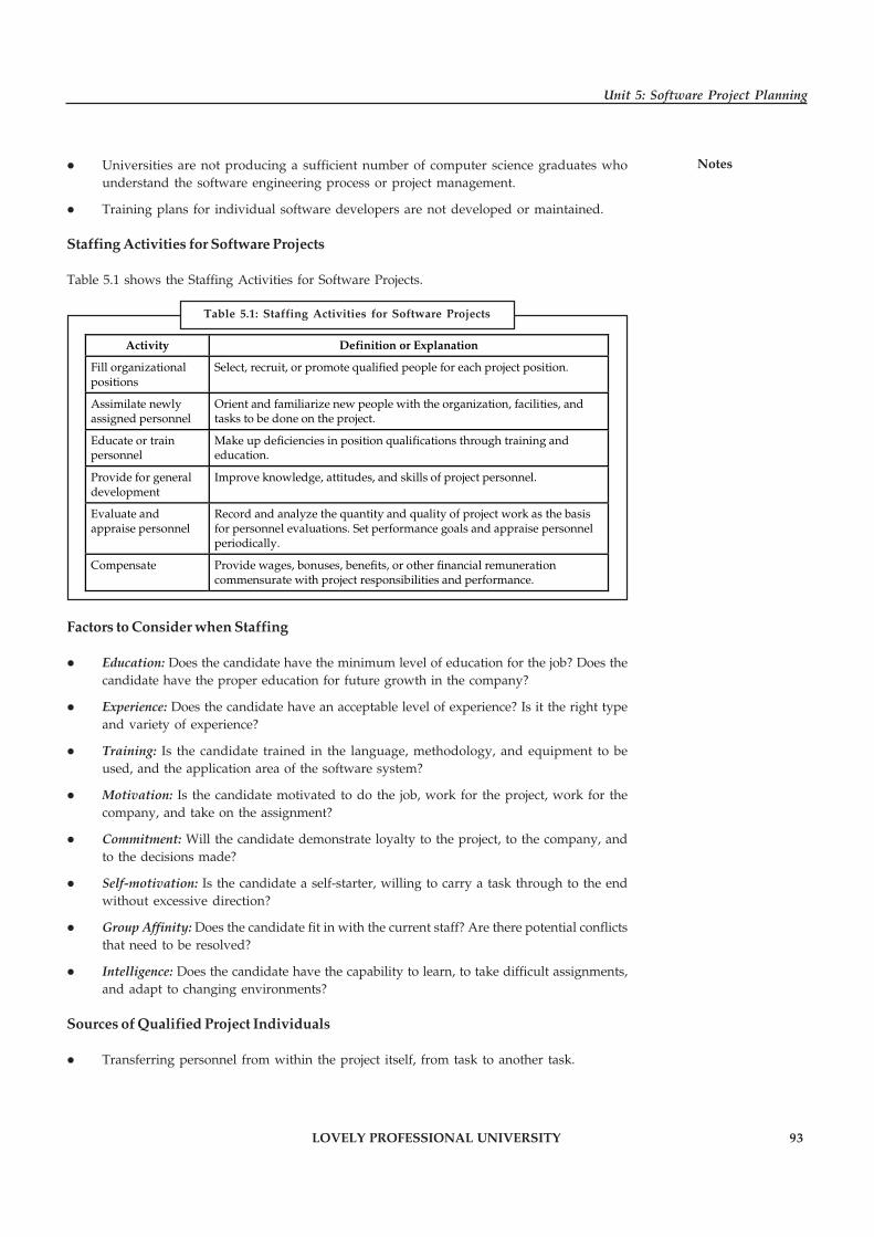
LOVELY PROFESSIONAL UNIVERSITY 93
Unit 5: Software Project Planning
Notes� Universities are not producing a sufficient number of computer science graduates whounderstand the software engineering process or project management.
� Training plans for individual software developers are not developed or maintained.
Staffing Activities for Software Projects
Table 5.1 shows the Staffing Activities for Software Projects.
Activity Definition or Explanation
Fill organizational positions
Select, recruit, or promote qualified people for each project position.
Assimilate newly assigned personnel
Orient and familiarize new people with the organization, facilities, and tasks to be done on the project.
Educate or train personnel
Make up deficiencies in position qualifications through training and education.
Provide for general development
Improve knowledge, attitudes, and skills of project personnel.
Evaluate and appraise personnel
Record and analyze the quantity and quality of project work as the basis for personnel evaluations. Set performance goals and appraise personnel periodically.
Compensate Provide wages, bonuses, benefits, or other financial remuneration commensurate with project responsibilities and performance.
Factors to Consider when Staffing
� Education: Does the candidate have the minimum level of education for the job? Does thecandidate have the proper education for future growth in the company?
� Experience: Does the candidate have an acceptable level of experience? Is it the right typeand variety of experience?
� Training: Is the candidate trained in the language, methodology, and equipment to beused, and the application area of the software system?
� Motivation: Is the candidate motivated to do the job, work for the project, work for thecompany, and take on the assignment?
� Commitment: Will the candidate demonstrate loyalty to the project, to the company, andto the decisions made?
� Self-motivation: Is the candidate a self-starter, willing to carry a task through to the endwithout excessive direction?
� Group Affinity: Does the candidate fit in with the current staff? Are there potential conflictsthat need to be resolved?
� Intelligence: Does the candidate have the capability to learn, to take difficult assignments,and adapt to changing environments?
Sources of Qualified Project Individuals
� Transferring personnel from within the project itself, from task to another task.
Table 5.1: Staffing Activities for Software Projects

94 LOVELY PROFESSIONAL UNIVERSITY
Principles of Software Engineering
Notes � Transfers from other projects within the organization, when other project has ended or isbeing cancelled.
� New hires from other companies through such methods as job fairs, referrals, headhunters,want ads, and unsolicited resumes.
� New college graduates can be recruited either through interviews on campus or throughreferrals from recent graduates who are now company employees.
� If the project manager is unable to obtain qualified individuals to fill positions, oneoption is to hire unqualified but motivated individuals and train them for those vacancies.
Self Assessment
Fill in the blanks:
7. The project …………………… provides a graphical representation of predicted tasks,milestones, dependencies, resource requirements, task duration, and deadlines.
8. The objective of …………………… is to define all project tasks, build a network thatdepicts their interdependencies, etc.
5.5 Introduction to Software Configuration Management
Different people defined SCM differently. The following are the some software configurationmanagement definitions:
� Software Configuration Management is the art of identifying, organizing, and controllingmodifications to the software being built by a programming team. The goal of is tomaximize productivity by minimizing mistakes.
� Software Configuration Management is the process of defining and implementing astandard configuration that results into the primary benefits such as easier step-up andmaintenance, less down time, better integration with enterprise management, and moreefficient and reliable backups.
� Software Configuration Management is the process concerned with the development ofprocedures and standards for managing an evolving software system product.
� Software Configuration Management is the ability to control and manage change in asoftware project.
� Software Configuration Management is a set of procedures meant to identify, control,provide and log the various work products of software project.
� In the simplest sense, Software Configuration Management is the process of controllingbaseline software documents and code.
5.5.1 Baselines
In accordance of IEEE Standards 729, a baseline is “a specification or product that has beenformally reviewed and agreed upon, that thereafter serves as the basis for further development,and that can be changed only through formal change control procedures.”
The baseline uses the shared project database. It is an SCM task to maintain the integrity of theset of artifacts. An approach to the integrity issue is to require approval for adding items to thebaseline. A second part to maintaining integrity is dealing with modifications to items in thedatabase.
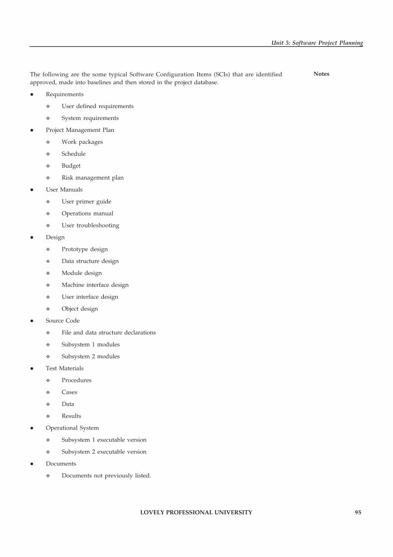
LOVELY PROFESSIONAL UNIVERSITY 95
Unit 5: Software Project Planning
NotesThe following are the some typical Software Configuration Items (SCIs) that are identifiedapproved, made into baselines and then stored in the project database.
� Requirements
� User defined requirements
� System requirements
� Project Management Plan
� Work packages
� Schedule
� Budget
� Risk management plan
� User Manuals
� User primer guide
� Operations manual
� User troubleshooting
� Design
� Prototype design
� Data structure design
� Module design
� Machine interface design
� User interface design
� Object design
� Source Code
� File and data structure declarations
� Subsystem 1 modules
� Subsystem 2 modules
� Test Materials
� Procedures
� Cases
� Data
� Results
� Operational System
� Subsystem 1 executable version
� Subsystem 2 executable version
� Documents
� Documents not previously listed.

96 LOVELY PROFESSIONAL UNIVERSITY
Principles of Software Engineering
Notes 5.5.2 Software Configuration Items
Software configuration items that comprise all information produced as part of the softwareengineering process are called a software configuration. Artifacts produced during the processare called Software Configuration Items (SCIs).
Example: Software configuration items are:
� Management plans (Project Plan, Test Plan, etc.)
� Specification (Requirements, Design, Test Case, etc.)
� Customer documentation (Implementation Manual, User Manuals, Operations Manuals,On-Line help files)
� Source code (PL/I Fortran, COBOL, Visual Basic, Visual C, etc.)
� Executable code (Machine readable object code, exe’s, etc.)
� Libraries (Runtime Libraries, Procedures, API’s DLL’s, etc.)
� Database (Data being Processed, Data a program requires, test data, Regression test data,etc.)
� Production documentation.
5.5.3 The SCM Process
The procedures for software configuration management are laid down in the form of a SCMplan document. Sample structure of a configuration management plan is provided in Table 5.2.
Introduction
� Purpose
� Scope
� Definitions and acronym
� References
Management
� Organizations
� Configuration Management Responsibilities
� Interface Control
� Implementation of Software Configuration Management Plan
� Applicable policies, Directives and Procedures
Configuration Management Activities
� Configuration Identification
� Configuration Control
� Configuration Status Accounting
� Audits and Reviews
Tools, Techniques and Methodologies
Supplier Control
Records Collection and Retention
Table 5.2: Software Configuration Management Plan

LOVELY PROFESSIONAL UNIVERSITY 97
Unit 5: Software Project Planning
Notes5.5.4 Identification of Objects in the Software Configuration
The following are the major objectives of software configuration standards:
� Remote system administration
� Reduced user down-time
� Reliable data backups
� Easy workstation set-up
� Multi-user support
� Remote software installation
Remote System Administration
� The configuration standard should include necessary software and/or privileges for remotesystem administration tools.
� A remote administration client that is correctly and configured on the client side is thecornerstone of the remotely administered network.
� These remote tools can be used to check the version of virus protection, check machineconfiguration or offer remote help-desk functionality.
Reduced User Downtime
� A great advantage of using a standard configuration is that systems become completelyinterchangeable resulting in reduced user down time.
� If a given system experiences an unrecoverable error, an identical new system can bedropped into place.
� User data can be transferred if the non-functional machine is still accessible, or the mostrecent copy can be pulled off of the backup tape with the ultimate global being that theuser experiences little change in the system interface.
Reliable Data Backups
� Using a standard directory for user data allows backup systems to selectively back up asmall portion of a machine, greatly reducing the network traffic and tape usage for backupsystems. Also, should a catastrophic failure occur the data directory could be restored to anew machine with little time and effort.
� A divided directory structure, between system and user data, is one of the main goals ofthe configuration standard.
Easy Workstation Set-up
� Any sort of standardized configuration streamlines the process of setting up the systemand insures that vital components are available.
� If multiple machines are being set-up according to a standard set-up most of the set-up andconfiguration can be automated.

98 LOVELY PROFESSIONAL UNIVERSITY
Principles of Software Engineering
Notes Multi-User Support
� Although it is not common for users to share a workstation, the system configuration isdesigned to allow multiple users the same workstation without interfacing with eachother’s work.
� Some software packages do not support completely independent settings for all users;however, users can have independent data areas.
� The directory structure implemented does not impose limits on the number of independentusers a system can have.
Remote Software Installation
� Most modern software packages are installed in factory pre-defined directories. Whilesoftware installed in this manner will function correctly for a single user, it will lead tonon-uniform configuration among a collection of machines.
� A good configuration standard will have software installed in specified directory areas tologically divide software on the disk.
� This will lead to easier identification of installed components and the possibility ofautomating installation procedures through the use of universal scripts.
� With software installed into specific directories, maintenance and upgrading runningsoftware becomes less complex.
Self Assessment
Fill in the blanks:
9. …………………… is the process concerned with the development of procedures andstandards for managing an evolving software system product.
10. Artifacts produced during the process are called …………………….
5.6 Quality Plan
According to Juran, there remains need for quality as it involves “fitness for use as seen by theuser” (or, rather, something like “approximate fitness for use as seen by a big enough group ofusers”). Put at its most simple, we define service quality management as the processes andsystems used to monitor and manage the service provided by a company. We see it as part of anoperator’s OSS (Operational Support System).
Notes An OSS is net of computerised systems that support the business and operationalprocesses peculiar to the online business industry.
The purpose of the Software Quality Plan is to define the techniques, procedures, andmethodologies that will be used to assure timely delivery of the software and that the developmentsystem meets the specified requirements within project resources.
Software Quality Assurance is a process for evaluating and documenting the quality of the workproducts produced during each stage of the software development lifecycle. The primary objectiveof the SQA process is to ensure the production of high-quality work products according to stated

LOVELY PROFESSIONAL UNIVERSITY 99
Unit 5: Software Project Planning
Notesrequirements and established standards. The list of SQA process objectives could be expandedwith formulating quality management approach, effective software engineering technology(its tools and methods), dealing with multi testing strategy, controlling of software documentationand its changes, as well as defining measurement and reporting mechanisms.
Quality plan discusses the procedures and software engineering processes which are covered byquality assurance controls such as:
� Monitoring quality assurance of the management team throughout the software
� engineering process
� Development and documentation of software development, evaluation and acceptancestandards and conventions
� Verifying the test results
� Tracking problem solving and corrective actions needed as a result of testing
Self Assessment
Fill in the blanks:
11. The purpose of the Software …………………… is to define the techniques, procedures, andmethodologies that will be used to assure timely delivery of the software.
12. …………………… is a process for evaluating and documenting the quality of the workproducts produced during each stage of the software development lifecycle.
5.7 Risk Management
In risk management, a prioritization process is followed whereby the risks with the greatestloss and the greatest probability of occurring are handled first, and risks with lower probabilityof occurrence and lower loss are handled in descending order. In practice the process can be verydifficult, and balancing between risks with a high probability of occurrence but lower lossversus a risk with high loss but lower probability of occurrence can often be mishandled.
Intangible risk management identifies a new type of a risk that has a 100% probability ofoccurring but is ignored by the organization due to a lack of identification ability.
Example: When deficient knowledge is applied to a situation, a knowledge riskmaterialises.
Relationship risk appears when ineffective collaboration occurs. Process-engagement risk maybe an issue when ineffective operational procedures are applied. These risks directly reduce theproductivity of knowledge workers, decrease cost effectiveness, profitability, service, quality,reputation, brand value, and earnings quality. Intangible risk management allows riskmanagement to create immediate value from the identification and reduction of risks thatreduce productivity.
Risk management also faces difficulties allocating resources. This is the idea of opportunity cost.Resources spent on risk management could have been spent on more profitable activities.Again, ideal risk management minimizes spending while maximizing the reduction of thenegative effects of risks.
The term risk is defined as the potential future harm that may arise due to some present actions.Risk management in software engineering is related to the various future harms that could be
100 LOVELY PROFESSIONAL UNIVERSITY
Principles of Software Engineering
Notes possible on the software due to some minor or non-noticeable mistakes in software developmentproject or process. “Software projects have a high probability of failure so effective softwaredevelopment means dealing with risks adequately (www.thedacs.com).” Risk management isthe most important issue involved in the software project development. This issue is generallymanaged by Software Project Management (SPM). During the life cycle of software projects,various risks are associated with them. These risks in the software project is identified andmanaged by software risk management which is a part of SPM. Some of the important aspects ofrisk management in software engineering are software risk management, risk classification andstrategies for risk management.
5.7.1 Software Risk Management
Since there could be various risks associated with the software development projects, the key toidentify and manage those risks is to know about the concepts of software risk management.Many concepts about software risk management could be identified but the most important arerisk index, risk analysis, and risk assessment.
1. Risk Index: Generally risks are categorized into two factors namely impact of risk eventsand probability of occurrence. Risk index is the multiplication of impact and probabilityof occurrence. Risk index can be characterized as high, medium, or low depending uponthe product of impact and occurrence. Risk index is very important and necessary forprioritization of risk.
2. Risk Analysis: There are quite different types of risk analysis that can be used. Basically,risk analysis is used to identify the high risk elements of a project in software engineering.Also, it provides ways of detailing the impact of risk mitigation strategies. Risk analysishas also been found to be most important in the software design phase to evaluate criticalityof the system, where risks are analyzed and necessary counter measures are introduce.The main purpose of risk analysis is to understand risks in better ways and to verify andcorrect attributes. A successful risk analysis includes important elements like problemdefinition, problem formulation, data collection.
3. Risk Assessment: Risk assessment is another important case that integrates risk managementand risk analysis. There are many risk assessment methodologies that focus on differenttypes of risks. Risk assessment requires correct explanations of the target system and allsecurity features. It is important that a risk referent levels like performance, cost, supportand schedule must be defined properly for risk assessment to be useful.
Task Analyse the importance of risk analysis and risk assessment.
5.7.2 Risk Classification
The key purpose of classifying risk is to get a collective viewpoint on a group of factors. Theseare the types of factors which will help project managers to identify the group that contributesthe maximum risk. A best and most scientific way of approaching risks is to classify them basedon risk attributes. Risk classification is considered as an economical way of analyzing risks andtheir causes by grouping similar risks together into classes (Hoodat, H. & Rashidi, H.). Softwarerisks could be classified as internal or external. Those risks that come from risk factors withinthe organization are called internal risks whereas the external risks come from out of theorganization and are difficult to control. Internal risks are project risks, process risks, andproduct risks. External risks are generally business with the vendor, technical risks, customers’

LOVELY PROFESSIONAL UNIVERSITY 101
Unit 5: Software Project Planning
Notessatisfaction, political stability and so on. In general, there are many risks in the softwareengineering which is very difficult or impossible to identify all of them. Some of most importantrisks in software engineering project are categorized as software requirement risks, softwarecost risks, software scheduling risk, software quality risks, and software business risks. Theserisks are explained in detail below:
5.7.3 Strategies for Risk Management
During the software development process various strategies for risk management could beidentified and defined according to the amount of risk influence. Based upon the amount of riskinfluence in software development project, risk strategies could be divided into three classesnamely careful, typical, and flexible. Generally, careful risk management strategy is projectedfor new and inexperienced organizations whose software development projects are connectedwith new and unproven technology; typical risk management strategy is well-defined as asupport for mature organizations with experience in software development projects and usedtechnologies, but whose projects carry a decent number of risks; and flexible risk managementstrategy is involved in experienced software development organizations whose softwaredevelopment projects are officially defined and based on proven technologies.
In this way, software risk management, risks classification, and strategies for risk managementare clearly described in this paper. If risk management process is in place for each and everysoftware development process then future problems could be minimized or completelyeradicated. Hence, understanding various factors under risk management process and focusingon risk management strategies explained above could help in building risk free products infuture.
Self Assessment
Fill in the blanks:
13. …………………… risk management identifies a new type of a risk that has a 100%probability of occurring but is ignored by the organization due to a lack of identificationability.
14. …………………… is the multiplication of impact and probability of occurrence.
5.8 Project Monitoring
Somebody says that person X is a very good planner but his/her execution policies are verypoor then it will make her/his a bad manager. A good plan is useless unless it is properlyexecuted. Consequently, the major management activity during the project is to ensure that theplan is properly executed, and when needed, to modify plans appropriately. Project assessmentwill be straightforward if everything went according to plan and no changes occurred in therequirements. However, on large projects, deviations from the original plan and changes torequirements are both to be expected. In these cases, the plan should be modified. Modificationsare also needed as more information about the project becomes available or due to personnelturnover.
The project control phase of the management activity is the longest. For this kind of routinemanagement activity, lasting for a long period of time, proper project monitoring can play asignificant role in aiding project management. However, all the methods, that the managementintends to use to monitor the project, should be planned before during the planning phase, sothat management is prepared to handle the changes and deviations from the plan and canrespond quickly. In this section, we will discuss some methods for monitoring a project.
102 LOVELY PROFESSIONAL UNIVERSITY
Principles of Software Engineering
Notes 5.8.1 Time Sheets
Once project development commences, the management has to track the progress of the projectand the expenditure incurred on the project. Progress can be monitored by using the scheduleand milestones laid down in the plan. The earned value method can also be used.
The most common method of keeping track of expenditures is by the use of a time sheet. Thetime sheet records how much time different project members are spending on the differentidentified activities in the project.
The time sheet is a common mechanism for collecting raw data. Time sheets can be filled dailyor weekly. The data obtained from the time sheets can be used to obtain information regardingthe overall expenditure and its breakup among different tasks and different phases at any giventime.
Example: The effort distribution with phases in a particular organization can be obtainedfrom the time sheets.
!Caution By assigning codes to projects, tasks within a project, and the nature of the workbeing done, time sheet processing can easily be automated.
5.8.2 Reviews
We discussed reviews at some length in an earlier section. We will not go into details of reviewshere; we’ll just comment on a few points regarding the monitoring aspect of reviews. Asmentioned earlier, one of the purposes of reviews is to provide information for project control.Reviews provide a definite and clearly defined milestone. It forces the author of a product tocomplete the product before the review. Having this goal gives some impetus and motivationto complete the product. For monitoring, as we have discussed, reviews can provide a wealth ofinformation.
First, the review schedules can be used to determine how the project is progressing compared toits planned schedule. Then, the review reports indicate in which parts of the project theprogrammers/analysts are having difficulty. With this information, corrective action, such asreplacing a junior person with a senior person, can be taken. In addition, review reports provideinsight into the quality of the software being produced and the types of errors being detected.
5.8.3 Cost-Schedule-Milestone Graph
A cost-schedule-milestone graph represents the planned cost of different milestones. It alsoshows the actual cost of achieving the milestones gained so far. By having both the planned costversus milestones and the actual cost versus milestones on the same graph, the progress of theproject can be grasped easily.
The x-axis of this graph is time, where the months in the project schedule are marked. The y-axisrepresents the cost, in dollars or PMs. Two curves are drawn. One curve is the planned cost andplanned schedule, in which each important milestone of the project is marked. This curve can becompleted after the project plan is made. The second curve represents the actual cost and actualschedule, and the actual achievement of the milestones is marked. Thus, for each milestone, thepoint representing the time when the milestone is actually achieved and the actual cost ofachieving it are marked.

LOVELY PROFESSIONAL UNIVERSITY 103
Unit 5: Software Project Planning
NotesExample: A cost-schedule-milestone graph for the example is shown in Figure 5.2.
The chart shown in Figure 5.2 is for a hypothetical project whose cost is estimated to be $100K.Different milestones have been identified and a curve is drawn with these milestones. Themilestones in this project are PDR (preliminary design review), CDR (critical design review),Module 1 completion, Module 2 completion, integration testing, and acceptance testing. Foreach of these milestones some budget has been allocated based on the estimates. The plannedbudget is shown by a dotted line. The actual expenditure is shown with a bold line. This chartshows that only two milestones have been achieved, PDR and CDR, and though the project waswithin budget when PDR was complete, it is now slightly over budget.
5.8.4 Earned Value Method
The system design usually involves a small group of (senior) people. Having a large number ofpeople at the system design stage is likely to result in a not-very-cohesive design. After thesystem design is complete, a large number of programmers whose job is to do the detaileddesign, coding, and testing may enter the project. During these activities, proper monitoring ofpeople, progress of the different components, and progress of the overall project are important.
An effective method of monitoring the progress of a project (particularly, the phases aftersystem design) is the earned value method. The earned value method uses a Summary TaskPlanning Sheet (STPS). The STPS is essentially a Gantt chart, with each task (relating to anindependently assignable module) having an entry in the chart. Each task has the followingmilestones marked in STPS: detailed design, coding, testing, and integration.
Each milestone of a task is assigned an earned value, which is the value (in dollars or person-months) that will be “earned” on completion of this milestone. The sum of the assigned valuesfor all the milestones for a task is equal to the total cost assigned to this task (or the totalestimated effort required for this task).
At any given time, the total effort (or cost) spent on a particular task can be determined from thetime sheets. The total value earned can be determined by adding the earned value of all thecompleted milestones of that task. By comparing the earned value with the total cost spent, theproject manager can determine how far the project is deviating from the initial estimates andthen take the necessary actions.
It should be pointed out that, in general, the earned value will be somewhat less than the actualeffort spent on a task, because this method only attaches value to the completed milestones. Thework in progress does not get adequately represented in the earned value.
The STPS usually has much more detail than is needed by project management. The earned valueaspect can be summarized in an earned value summary report. This report summarizes theearned value for each task, the actual effort spent on that task, and how these compare for a givenpoint in time. The summary report can be produced monthly or biweekly.
Figure 5.2: A Cost-schedule Milestone Graph

104 LOVELY PROFESSIONAL UNIVERSITY
Principles of Software Engineering
Notes Self Assessment
Fill in the blanks:
15. The …………………… records how much time different project members are spending onthe different identified activities in the project.
16. …………………… provide a definite and clearly defined milestone.
�Case Study An Industrial Case Study of Implementing Software
Risk Management
Explicit risk management is gaining ground in industrial software developmentprojects. However, there are few empirical studies that investigate the transfer ofexplicit risk management into industry, the adequacy of the risk management
approaches to the constraints of industrial contexts, or their cost-benefit.
The objective of the case study was (1) to analyze the usefulness and adequacy of the Riskitmethod and (2) to analyze the cost-benefit of the Riskit method in this industrial context.
The Risk Management Method
The risk management method transferred in this case study is called Riskit. Riskit is acomprehensive risk management method that is based on sound theoretical principles,yet it has been designed to have sufficiently low overhead and complexity so that it can beused in real, time-constrained projects.
Figure 1: Overview on Riskit Process
Contd...
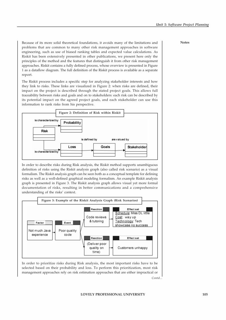
LOVELY PROFESSIONAL UNIVERSITY 105
Unit 5: Software Project Planning
NotesBecause of its more solid theoretical foundations, it avoids many of the limitations andproblems that are common to many other risk management approaches in softwareengineering, such as use of biased ranking tables and expected value calculations. AsRiskit has been extensively presented in other publications, we present here only theprinciples of the method and the features that distinguish it from other risk managementapproaches. Riskit contains a fully defined process, whose overview is presented in Figure1 as a dataflow diagram. The full definition of the Riskit process is available as a separatereport.
The Riskit process includes a specific step for analyzing stakeholder interests and howthey link to risks. These links are visualized in Figure 2: when risks are defined, theirimpact on the project is described through the stated project goals. This allows fulltraceability between risks and goals and on to stakeholders: each risk can be described byits potential impact on the agreed project goals, and each stakeholder can use thisinformation to rank risks from his perspective.
In order to describe risks during Risk analysis, the Riskit method supports unambiguousdefinition of risks using the Riskit analysis graph (also called risk scenario) as a visualformalism. The Riskit analysis graph can be seen both as a conceptual template for definingrisks as well as a well-defined graphical modeling formalism. An example Riskit analysisgraph is presented in Figure 3. The Riskit analysis graph allows visual yet more formaldocumentation of risks, resulting in better communications and a comprehensiveunderstanding of the risks’ context.
In order to prioritize risks during Risk analysis, the most important risks have to beselected based on their probability and loss. To perform this prioritization, most riskmanagement approaches rely on risk estimation approaches that are either impractical or
Contd...
Figure 2: Definition of Risk within Riskit
Figure 3: Example of the Riskit Analysis Graph (Risk Scenarios)

106 LOVELY PROFESSIONAL UNIVERSITY
Principles of Software Engineering
Notes theoretically questionable. For example, the expected value calculations (i.e., risk =probability * loss) are often impractical because accurate estimates of probability and lossare seldom available and it is difficult to account for multiple goal effects and for a non-linear utility function. Riskit largely avoids these problems by using ranking techniquesthat are appropriate for the type of information available. When ratio or distance scaledata are available for probability and loss, expected utility loss calculations are used.However, often only ordinal scale metrics are available for probability or utility loss. Forexample, the risk scenarios might be ranked in terms of probability and utility loss eachas shown in Figure 4.
To select in this case the most important risks based on the combination of probability andutility loss, a specific Riskit Pareto ranking technique is used. This technique uses a two-dimensional space to position risk scenarios by their relative probability and utility lossas shown in Figure 5. Using this technique, the evaluation of the risks is then based onutility theory. The value of this Riskit Pareto ranking technique is that it provides areliable and consistent ranking approach that only ranks risks as far as the input dataallows.
Source: http://mridulasharma.com/wp-content/uploads/2013/01/Assignment-1-Case-Study.pdf
Figure 4: Ordinal Metrics for Probability and Loss
Figure 5: Example of Riskit Pareto Table

LOVELY PROFESSIONAL UNIVERSITY 107
Unit 5: Software Project Planning
Notes5.9 Summary
� The project plan reflects the current status of all project activities and is used to monitorand control the project.
� Software Cost Estimation is widely considered to be a weak link in software projectmanagement. It requires a significant amount of effort to perform it correctly.
� Constructive Cost Model (COCOMO) is a method for assessing the cost of a softwarepackage.
� The project schedule provides a graphical representation of predicted tasks, milestones,dependencies, resource requirements, task duration, and deadlines.
� Software project scheduling is an activity that distributes estimated effort across the plannedproject duration by allocating the effort to specific software engineering tasks.
� Software Configuration Management is the art of identifying, organizing, and controllingmodifications to the software being built by a programming team.
� Software configuration items that comprise all information produced as part of the softwareengineering process are called a software configuration.
� The purpose of the Software Quality Plan is to define the techniques, procedures, andmethodologies that will be used to assure timely delivery of the software and that thedevelopment system meets the specified requirements within project resources.
� In risk management, a prioritization process is followed whereby the risks with thegreatest loss and the greatest probability of occurring are handled first, and risks withlower probability of occurrence and lower loss are handled in descending order.
5.10 Keywords
COCOMO: Constructive Cost Model (COCOMO) is a method for assessing the cost of a softwarepackage.
Earned Value: Earned Value (EV) is a management tool for tracking and communicating aproject’s status.
Estimation: Estimation is the process of finding an estimate, or approximation, which is a valuethat is usable for some purpose even if input data may be incomplete, uncertain, or unstable.
Project Planning: Project planning is a common thread that intertwines all the activities fromconception to commissioning and handing over the clockwork to clients.
Scheduling: Scheduling is the method by which threads, processes or data flows are given accessto system resources (e.g. processor time, communications bandwidth). This is usually done toload balance a system effectively or achieve a target quality of service.
Software Configuration Management: Software Configuration Management is the ability tocontrol and manage change in a software project.
Software Quality Plan: It defines the techniques, procedures, and methodologies that will beused to assure timely delivery of the software.
User: That person who actually performs his or her job functions with the assistance of theproduct.

108 LOVELY PROFESSIONAL UNIVERSITY
Principles of Software Engineering
Notes 5.11 Review Questions
1. “A plan is the first step in providing the means to satisfy the needs of a project sponsor andhelp in paving the way to reach desired goal.” Discuss.
2. Discuss the factors that contribute to inaccurate estimation.
3. Discuss the steps included in Software Cost estimation process.
4. What is COCOMO Model? Discuss the different levels of COCOMO model.
5. Explain the concept of project scheduling.
6. Discuss the issues included in staffing.
7. Describe the concept of Software Configuration Management.
8. What are software configuration items? Discuss.
9. Explain how to identify objects in the Software Configuration.
10. Based upon the amount of risk influence in software development project, risk strategiescould be divided into three classes. Comment.
Answers: Self Assessment
1. Project Planning 2. Resource planning
3. Cost 4. Work Break down
5. COCOMO 6. top-down
7. schedule 8. Project manager
9. Software Configuration Management 10. software configuration items
11. Quality Plan 12. Software Quality Assurance
13. Intangible 14. Risk index
15. time sheet 16. Reviews
5.12 Further Readings
Books Rajib Mall, Fundamentals of Software Engineering, 2nd Edition, PHI.
Richard Fairpy, Software Engineering Concepts, Tata McGraw Hill, 1997.
R.S. Pressman, Software Engineering – A Practitioner’s Approach, 5th Edition, TataMcGraw Hill Higher education.
Sommerville, Software Engineering, 6th Edition, Pearson Education
Online links http://www.csbdu.in/econtent/Software%20Engineering/Unit_II.pdf
http://www.slideshare.net/PiyushGogia/chapter-4-software-project-planning
http://www.bth.se/fou/cuppsats.nsf/all/d4d4c4f99af27b2cc1256f5b004aa0c0/$file/The%20Relationship%20between%20Project%20Planning%20and%20Project%20Success.pdf
http://www.mhhe.com/engcs/compsci/pressman/graphics/Pressman5sepa/common/cs2/projplan.pdf

LOVELY PROFESSIONAL UNIVERSITY 109
Unit 6: Functional Design
NotesUnit 6: Functional Design
CONTENTS
Objectives
Introduction
6.1 Design Process
6.1.1 Features of a Good Design
6.2 Principles of Design
6.3 Design Concepts
6.3.1 Abstraction
6.3.2 Modularity
6.3.3 Top Down and Bottom Up Approach
6.4 Coupling
6.5 Cohesion
6.6 Structure Chart
6.7 Data Flow Diagrams
6.7.1 Components of Data Flow Diagrams
6.8 Design Heuristics
6.9 Summary
6.10 Keywords
6.11 Review Questions
6.12 Further Readings
Objectives
After studying this unit, you will be able to:
� Discuss the principles of design
� Discuss the concept of abstraction, modularity, top down and bottom up approach
� Explain coupling and cohesion.
� Discuss the concept of structure charts and data flow diagrams
� Explain design heuristics
Introduction
The systems objectives outlined during the feasibility study serve as the basis from which thework of system design is initiated. Much of the activities involved at this stage are of technicalnature requiring a certain degree of experience in designing systems, sound knowledge ofcomputer related technology and through understanding of computers available in the market
110 LOVELY PROFESSIONAL UNIVERSITY
Principles of Software Engineering
Notes and the various facilities provided by the vendors. Nevertheless, a system cannot be designed inisolation without the active involvement of the user. The user has a vital role to play at this stagetoo. As we know that data collected during feasibility study will be utilized systematicallyduring the system design. It should, however, be kept in mind that detailed study of the existingsystem is not necessarily over with the completion of the feasibility study. Depending on theplan of feasibility study, the level of detailed study will vary and the system design stage willalso vary in the amount of investigation that still needs to be done. Sometimes, but rarely, theinvestigation may form a separate stage between feasibility study and computer system design.Designing a new system is a creative process which calls for logical as well as lateral thinking.The logical approach involves systematic moves towards the end-product keeping in mind thecapabilities of the personnel and the equipment. This is to ensure that no efforts are being madeto fit previous solutions into new situations.
6.1 Design Process
Design transforms the information model created during analysis stage into data structures inorder to implement the software. E-R diagrams and the data dictionaries are used as the basis forthe design activities.
The architectural design defines the relationship between structural elements of the software,the design patterns and the constraints. The interface design model describes how the softwarecommunicates with itself, with the system and with the humans who use it. Thus an interfacedepicts a flow of information and behavior. The component-level design converts the structuralelements of the software architecture into a procedural description of software components.This information can be obtained in the form of PSPEC, CSPEC and STD.
Thus, a design affects the effectiveness of the software that is being built. It fosters the quality ofthe software engineering.
6.1.1 Features of a Good Design
� It must implement all the explicit requirements contained in the analysis stage and all theimplicit requirements mentioned by the customer.
� It must be readable and understandable for those who code, test and support.
� It must address the data, functional and behavioral aspects for the implementation of thesoftware.
� It must exhibit an architectural structure.
� It must be modular i.e. the software must be partitioned into separate logical units toperform specific functions.
� It must contain distinct representation of data, architecture, interface and modules.
Self Assessment
Fill in the blanks:
1. The …………………… design defines the relationship between structural elements of thesoftware, the design patterns and the constraints.
2. The …………………… design converts the structural elements of the software architectureinto a procedural description of software components.

LOVELY PROFESSIONAL UNIVERSITY 111
Unit 6: Functional Design
Notes6.2 Principles of Design
Design is both a process and a model. Good design is a result of creative skills, past experienceand a commitment to quality. Basic design principles allow a software engineer to ship throughthe design process. The principles listed below are suggested by Davis:
1. The design process must not suffer from “tunnel” vision. It must consider alternativeapproaches based on alternative requirements, resources available and the design concepts.
2. The design should be traceable to the analysis model. Because the design includes a lot ofrequirements, there must be a clear indication of the tracking of all these requirements inthe design document.
3. The design must not reinvent the wheel. Because of time and resource constraint designmust always try to implement new ideas using the already existing design patterns.
4. The design should minimize the distance between the software and the problem, i.e.design must mimic the structure of the problem domain.
5. The design must exhibit uniformity and integration. While creating the design standardstyles and formats should be followed by the design team. The design components shouldbe carefully integrated and the interfaces should be clearly defined.
6. The design should be structured to accommodate change.
7. The design should be structured to degrade eventually in the event of abnormal data,events and circumstances.
8. Design must be separated from coding in terms of data abstraction. Thus, the level of datahiding is higher in design than in coding. While coding every minute detail must be takencare of.
9. The design must be assessed for quality during creation.
10. The design must be reviews to minimize the semantic errors.
Self Assessment
State whether the following statements are true or false:
3. The design should be traceable to the analysis model.
4. The design should maximize the distance between the software and the problem.
6.3 Design Concepts
A number of design concepts exist which provide the software designer sophisticated designmethods to be applied. These concepts answer a lot of questions like the following:
1. Which criteria should be used to decompose the software into multiple components?
2. How is the data or functional detail isolated from the conceptual representation of thesoftware?
3. What uniform criteria must be applied to define the design quality?

112 LOVELY PROFESSIONAL UNIVERSITY
Principles of Software Engineering
Notes 6.3.1 Abstraction
Abstraction is the elimination of the irrelevant and amplification of the essentials. A number oflevels of abstraction exist in a modular design. At the highest level, the solution is mentioned ata very broad level in terms of the problem. At the lower levels, a procedure oriented action istaken wherein problem oriented design is coupled with implementation level design. At thelowest level, the solution is mentioned in the form that can be directly used for coding.
The various levels of abstraction are as follows:
� Procedural Abstraction: It is a sequence of instructions that have limited functions in aspecific area. For example, the word “prepare” for tea. Although it involves a lot of actionslike going to the kitchen, boiling water in the kettle, adding tea leaves, sugar and milk,removing the kettle from the gas stove and finally putting the gas off.
� Data Abstraction: It is a named collection of data that describes the data object. Forexample, data abstraction for prepare tea will used kettle as a data object which in turnwould contain a number of attributes like brand, weight, color, etc.
� Control Abstraction: It implies a program control mechanism without specifying itsinternal details.
Example: Synchronization semaphore in operating system which is used for coordinationamongst various activities.
6.3.2 Modularity
Modularity refers to the division of software into separate modules which are differently namedand addressed and are integrated later on in order to obtain the completely functional software.It is the only property that allows a program to be intellectually manageable. Single largeprograms are difficult to understand and read due to large number of reference variables,control paths, global variables, etc. The desirable properties of a modular system are:
� Each module is a well defined system that can be used with other applications.
� Each module has a single specific purpose.
� Modules can be separately compiled and stored in a library.
� Modules can use other modules.
� Modules should be easier to use than to build.
� Modules are simpler from outside than inside.
Modularity thus enhances the clarity of design which in turn eases coding, testing, debugging,documenting and maintenance of the software product.
Notes It might seem to you that on dividing a problem into sub problems indefinitely,the effort required to develop it becomes negligibly small. However, the fact is that ondividing the program into numerous small modules, the effort associated with theintegration of these modules grows. Thus, there is a number N of modules that result inthe minimum development cost. However, there is no defined way to predict the value ofthis N.
LOVELY PROFESSIONAL UNIVERSITY 113
Unit 6: Functional Design
NotesIn order to define a proper size of the modules, we need to define an effective design method todevelop a modular system. Following are some of the criteria defined by Meyer for the same:
� Modular Decomposability: The overall complexity of the program will get reduced if thedesign provides a systematic mechanism to decompose the problem into sub-problemsand will also lead to an efficient modular design.
� Modular Composability: If a design method involves using the existing design componentswhile creating a new system it will lead to a solution that does not re-invent the wheel.
� Modular Understandability: If a module can be understood as a separate stand-alone unitwithout referring to other modules it will be easier to build and edit.
� Modular Continuity: If a change made in one module does not require changing all themodules involved in the system, the impact of change-induced side effects gets minimized.
� Modular Protection: If an unusual event occurs affecting a module and it does not affectother modules, the impact of error-induced side effects will be minimized.
6.3.3 Top Down and Bottom Up Approach
A system consists of components, which have components of their own; indeed a system is ahierarchy of components. The highest-level component correspond to the total system. To designsuch a hierarchy there are two possible approaches: top-down and bottom-up.
A top-down design approach starts by identifying the major components of the system,decomposing them into their lower-level components and iterating until the desired level ofdetail is achieved. Top-down design methods often result in some form of step-wise refinement.
Starting from an abstract design, in each step the design is refined to a more concrete level, untilwe reach a level where no more refinement is needed and the design can be implementeddirectly. Most design methodologies are based on the top-down approach.
A bottom-up design approach starts with designing the most basic or primitive components andproceeds to higher-level components that use these lower-level components.
Bottom-up methods work with layers of abstraction. Starting from the very bottom, operationsthat provide a layer of abstraction are implemented. The operations of this layer are then usedto implement more powerful operations and a still higher layer of abstraction, until the stage isreached where the operations supported by the layer are those desired by the system.
A top-down approach is suitable only if the specifications of the system are clearly known andthe system development is from scratch. If a system is to be built from an existing system, abottom-up approach is more suitable, as it starts from some existing components.
Example: If an iterative enhancement type of process is being followed, in later iterations,the bottom-up approach could be more suitable (in the first iteration a top down approach canbe used).
� Pure top-down or pure bottom-up approaches are often not practical.
� Combine approaches is also use full for layer of abstraction.
� This approach is frequently used for developing systems.

114 LOVELY PROFESSIONAL UNIVERSITY
Principles of Software Engineering
Notes Self Assessment
Fill in the blanks:
5. …………………… is the elimination of the irrelevant and amplification of the essentials.
6. …………………… methods work with layers of abstraction.
6.4 Coupling
Coupling is the measure of degree of interdependence amongst modules. Two modules that aretightly coupled are strongly dependent on each other. However, two modules that are looselycoupled are not dependent on each other. Uncoupled modules have no interdependence at allwithin them. The various types of coupling techniques are depicted in Figure 6.1.
Uncoupled: no dependence
Loosely coupled: some dependence
Highly coupled: large dependence
A good design is the one that has low coupling. Coupling is measured by the number ofinterconnections between the modules. That the coupling increases as the number of calls betweenmodules increase or the amount of shared data is large.
Did u know? A design with high coupling will have more errors.
Different types of coupling are content, common, external, control, stamp and data. The level ofcoupling in each of these types is given in Figure 6.2.
Data couplingStamp couplingControl couplingExternal couplingCommon couplingContent coupling
The direction of the arrow in Figure 6.2 points from the lowest coupling to highest coupling. Thestrength of coupling is influenced by the complexity of the modules, the type of connection andthe type of communication. Modifications done in the data of one block may require changes inother block of a different module which is coupled to the former module. However, if thecommunication takes place in the form of parameters then the internal details of the modulesare no required to be modified while making changes in the related module.
Figure 6.1: Module Coupling
Figure 6.2: Types of Modules Coupling
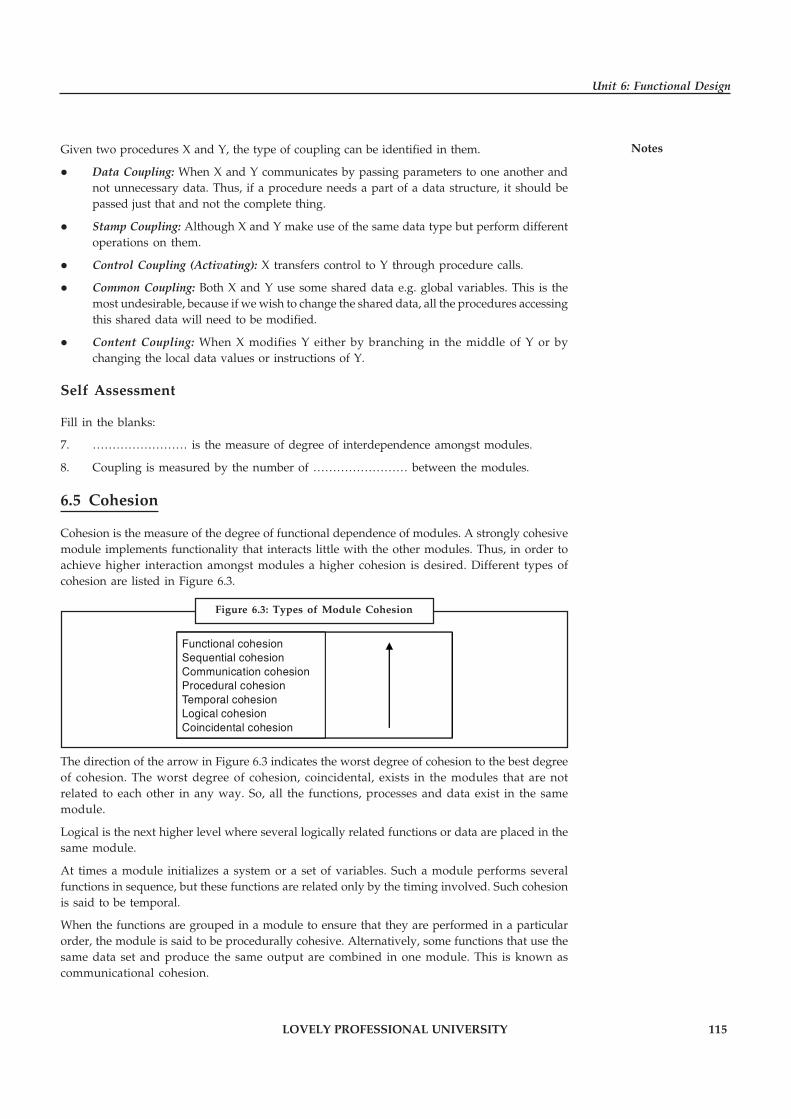
LOVELY PROFESSIONAL UNIVERSITY 115
Unit 6: Functional Design
NotesGiven two procedures X and Y, the type of coupling can be identified in them.
� Data Coupling: When X and Y communicates by passing parameters to one another andnot unnecessary data. Thus, if a procedure needs a part of a data structure, it should bepassed just that and not the complete thing.
� Stamp Coupling: Although X and Y make use of the same data type but perform differentoperations on them.
� Control Coupling (Activating): X transfers control to Y through procedure calls.
� Common Coupling: Both X and Y use some shared data e.g. global variables. This is themost undesirable, because if we wish to change the shared data, all the procedures accessingthis shared data will need to be modified.
� Content Coupling: When X modifies Y either by branching in the middle of Y or bychanging the local data values or instructions of Y.
Self Assessment
Fill in the blanks:
7. …………………… is the measure of degree of interdependence amongst modules.
8. Coupling is measured by the number of …………………… between the modules.
6.5 Cohesion
Cohesion is the measure of the degree of functional dependence of modules. A strongly cohesivemodule implements functionality that interacts little with the other modules. Thus, in order toachieve higher interaction amongst modules a higher cohesion is desired. Different types ofcohesion are listed in Figure 6.3.
Functional cohesionSequential cohesionCommunication cohesionProcedural cohesionTemporal cohesionLogical cohesionCoincidental cohesion
The direction of the arrow in Figure 6.3 indicates the worst degree of cohesion to the best degreeof cohesion. The worst degree of cohesion, coincidental, exists in the modules that are notrelated to each other in any way. So, all the functions, processes and data exist in the samemodule.
Logical is the next higher level where several logically related functions or data are placed in thesame module.
At times a module initializes a system or a set of variables. Such a module performs severalfunctions in sequence, but these functions are related only by the timing involved. Such cohesionis said to be temporal.
When the functions are grouped in a module to ensure that they are performed in a particularorder, the module is said to be procedurally cohesive. Alternatively, some functions that use thesame data set and produce the same output are combined in one module. This is known ascommunicational cohesion.
Figure 6.3: Types of Module Cohesion

116 LOVELY PROFESSIONAL UNIVERSITY
Principles of Software Engineering
Notes If the output of one part of a module acts as an input to the next part, the module is said to havesequential cohesion. Because the module is in the process of construction, it is possible that itdoes not contain all the processes of a function.
Notes The most ideal of all module cohesion techniques is functional cohesion. Here,every processing element is important to the function and all the important functions arecontained in the same module. A functionally cohesive function performs only one kindof function and only that kind of function.
Given a procedure carrying out operations A and B, we can identify various forms of cohesionbetween A and B:
� Functional Cohesion: A and B are part of one function and hence, are contained in the sameprocedure.
� Sequential Cohesion: A produces an output that is used as input to B. Thus they can be apart of the same procedure.
� Communicational Cohesion: A and B take the same input or generate the same output.They can be parts of different procedures.
� Procedural Cohesion: A and B are structured in the similar manner. Thus, it is not advisableto put them both in the same procedure.
� Temporal Cohesion: Both A and B are performed at moreover the same time. Thus, theycannot necessarily be put in the same procedure because they may or may not be performedat once.
� Logical Cohesion: A and B perform logically similar operations.
� Coincidental Cohesion: A and B are not conceptually related but share the same code.
Task Compare and contrast coupling and cohesion.
Self Assessment
Fill in the blanks:
9. …………………… is the measure of the degree of functional dependence of modules.
10. If the output of one part of a module acts as an input to the next part, the module is said tohave …………………… cohesion.
6.6 Structure Chart
There are many techniques for effectively communicating organizational ideas within thebusiness environment. A structure chart is a graphical chart used for the purpose of describingand communicating a model or process within an organization. This chart typically consists ofshapes with descriptions and connecting lines that show relationships to other shapes within thechart.
Project managers rely on structure charts for managing their daily activities. The most widelyused structure chart for project management is the work breakdown structure chart. This is a

LOVELY PROFESSIONAL UNIVERSITY 117
Unit 6: Functional Design
Notesgraphical chart that consists of milestones and timelines. These timelines show the tasks thatmust be completed to successfully finish a project.
Functional modeling is a system engineering technique that requires the graphical design andpresentation of complex business models. This visualization design approach provides an elegantmethod for describing information to a non-technical audience. The functional model decomposesthe detail interfaces of a software application into clearly defined components.
Example: An organization chart is well known example of a structure chart that is usedwithin most business operations. This chart is a graphical representation of the employees in anorganization. It is typically displayed in a hierarchical manner with the senior executiverepresented at the top of the chart.
The study of organizational behavior is the art of describing how individuals and groups withinan organization interact with other teams or departments. This collaboration and communicationparadigm is typically referred to as group dynamics. A structure chart is used withinorganizational theory to describe individual groups and their interactions with other groups ofan organization.
Structured analysis and design is an approach for managing the development process ofapplications within software engineering. This design pattern is based on a waterfall systemsdevelopment method. The waterfall systems design approach includes specific structure chartsfor each phase of the development process including requirements, design, coding, and testing.
A data model is a structure chart used within structured analysis. This structure chart describesthe relationships of data within a database. The data model defines the business rules andcardinality of data for an application. This chart describes how the user of a system will interactwith the data.
The art of systems architecture requires effective communication at multiple technical levelswithin an organization. The system architect leverages visualization artifacts to describe eventswithin an enterprise. This graphical representation of ideas creates a better overall understandingof how system components will interact with other interfaces throughout the enterprise.
Figure 6.4 shows the structure chart for calculating and displaying the averages for a collectionof pairs of values.
Source : h t tp ://www.ece .uc .edu/~mazlack/CS2 . sp2008/CS2 . sc . examples/sc . tu tor ia l/SC.detailed.example.html
Figure 6.4: Structure Chart for Calculating and Displaying the Averagesfor a Collection of Pairs of Values

118 LOVELY PROFESSIONAL UNIVERSITY
Principles of Software Engineering
Notes The following things should be noted about the structure chart.
� Boxes representing procedures are divided by a line. The name of the procedure is abovethe line. The description of what the procedure does is in the narrative section of the box.The narrative section of the box should approximately match the pseudo-code. Generally,the comment in the procedure describing what the procedure does should alsoapproximately match the narrative description in the box.
� Boxes without dividing lines are not procedures.
� Boxes without dividing lines (non-procedures) generally should not be shown ascontrolling procedures. This is keeping with the idea of top-down design of top-mostboxes being the most general.
� The data coupling represents data flows into and out of the activities represented by theboxes. In general, non-procedures should not be shown as controlling procedures.
� If possible, data coupling exiting an activity downward (in the structure chart) should beshown to the left of the line connecting the activities. data coupling exiting an activityupward should be shown to the right of the line.
� The data coupling names are those known in the top-most procedure. In the example, theprocedure IncomingNumbers knows the data as first and second. The procedure Average isinvoked by the procedure IncomingNumbers. IncomingNumbers knows the same data asleading and trailing. The structure chart shows first and second as the coupling betweenIncomingNumbers and Average. This is because IncomingNumbers is the controlling activity.
� Structure chart arrows indicate both the direction of information flow and what they do.Open circles are data and darkened circles are control information.
� In the example, the data coupling for EOF (end of file) is shown as a darkened circlebecause EOF is a control variable. EOF is used to decide if further activity in the iterationwill happen.
Iteration is shown by the iteration mark.
It indicates the activities that are iterated. In the example, the activity IncomingNumbers isshown as an iterated activity. The activities within it are not shown as iterated. This has theeffect on program implementation of this structure chart that iterative control must be inthe activity above IncomingNumbers.
Self Assessment
Fill in the blanks:
11. A …………………… is a graphical chart used for the purpose of describing andcommunicating a model or process within an organization.
12. A …………………… is a structure chart used within structured analysis.

LOVELY PROFESSIONAL UNIVERSITY 119
Unit 6: Functional Design
Notes6.7 Data Flow Diagrams
The data flow diagrams should also have some associated documentation. This is necessary asthe diagrams are meant as a visual representation of the way in which information is processed.There is limited space on the diagrams so that documentation to explain, refine and describefurther details of what is shown need to be kept somewhere in the proposed systemdocumentation. The data flow diagrams and the associated documentation together combine toform a data flow model. This is also commonly called a process model.
Before attempting to construct an initial DFD it is necessary to gather and digest informationthat helps us to understand how data is processed in the current system. Fact-finding techniquesare used for this purpose and are discussed in another Unit. As the DFD is constructed a systemsanalyst will often come across areas of doubt where the precise way to model the system isunclear. This is a natural part of the development and should not be regarded with alarm. In fact,it is expected and it is a consequence of attempting to model the current situation that questionswill be asked to clarify the exact processes which are taking place. Sometimes the analyst willmake an assumption and then check this with the user at a subsequent meeting.
Results of interviews, documents, reports, questionnaires etc. will all play a part in helping theanalyst to gain an insight into the current processes. Where a system is being developed fromscratch the analyst will work with the user to develop the proposed DFDs.
When all the information about the current system is gather it should be possible to constructthe DFDs to show:
� the information that enters and leaves the system
� the people/roles/other systems who generate and/or receive that information
� the processes that occur in the system to manipulate the information
� the information that is stored in the system
� the boundary of the system indicating what is (and what is not) included
As a starting point, it is sometimes useful to construct a document flow diagram. This diagramshows how ‘documents’ are passed around an organisation to fulfil the current requirements ofthe system under investigation. The term’ documents’ is interpreted very loosely and usuallytranslates to information.
Sometimes before beginning to produce the set of data flow diagrams a document flow diagramis generated. This helps to establish the system boundary so we can decide which parts of thesystem we are modelling and which parts we are not. The document flow diagram shows thedifferent documents (or information sources in the system and how they flow from a source toa recipient.
Example: Here is an example of a document flow diagram shown next page.
Here ellipses represent either the source or recipient of the ‘documents’ and named arrows showthe direction of transfer and the nature of the information being exchanged. This kind of diagramis a first step in understanding what information is in the system and how it is used to performthe required functions.
Another useful feature of the construction of this type of diagram is that it enables a sensiblediscussion of where the system boundary should lie. In other words it is important to establishwhat is to be included in the proposed information system and what is not. To indicate this, asystem boundary line is constructed on the document flow diagram.

120 LOVELY PROFESSIONAL UNIVERSITY
Principles of Software Engineering
Notes
The DFDs are used to:
� discuss with the user a diagrammatic interpretation of the processes in the system andclarify what is currently being performed
� determine what the new system should be able to do and what information is required foreach different process that should be carried out
� check that the completed system conforms to its intended design
6.7.1 Components of Data Flow Diagrams
The components of a Data Flow Diagram are always the same but there are different diagrammaticnotations used. The notation used here is one adopted by a methodology known as SSADM(Structured Systems Analysis and Design Methods). Luckily there are only four different symbolsthat are normally used on a DFD. The elements represented are:
� External entities
� Processes
� Data stores
� Data flows
External Entities
External entities are those things that are identified as needing to interact with the system underconsideration. The external entities either input information to the system, output informationfrom the system or both. Typically they may represent job titles or other systems that interactwith the system to be built.
Figure 6.5: Example of a Document Flow Diagram

LOVELY PROFESSIONAL UNIVERSITY 121
Unit 6: Functional Design
Notes
Administrator Manager
Payrollsystem
DataEntryClerk
Manager
Example: Some examples are given below in Figure 6.6. Notice that the SSADM symbolis an ellipse. If the same external entity is shown more than once on a diagram (for clarity) adiagonal line indicates this.
Task Analyse the function of external entities.
Processes
Processes are actions that are carried out with the data that flows around the system. A processaccepts input data needed for the process to be carried out and produces data that it passes on toanother part of the DFD. The processes that are identified on a design DFD will be provided inthe final artefact. They may be provided for using special screens for input and output or by theprovision of specific buttons or menu items. Each identifiable process must have a well chosenprocess name that describes what the process will do with the information it uses and the outputit will produce.
!Caution Process names must be well chosen to give a precise meaning to the action to betaken.
It is good practice to always start with a strong verb and to follow with not more than four orfive words.
Example: Good process names would be:
� Enter customer details
� Register new students
� Validate sales orders.
Try to avoid using the verb ‘process’, otherwise it is easy to use this for every process. Wealready know from the symbol it is a process so this does not help us to understand what kindof a process we are looking at.
Figure 6.6: Examples of External Entities

122 LOVELY PROFESSIONAL UNIVERSITY
Principles of Software Engineering
Notes The process symbol has three parts as shown in Figure 6.7.
Where/who
Process identifier
Process name
The process identifier is allocated so that each process may be referred to uniquely.
The sequence of the process identifiers is usually unimportant but they are frequently to be seenas 1, 2, 3, etc. The top right hand section of the box is used to describe where the process takesplace or who is doing the process.
Example: Process boxes are given in Figure 6.8.
Data Stores
Data stores are places where data may be stored. This information may be stored eithertemporarily or permanently by the user. In any system you will probably need to make someassumptions about which relevant data stores to include. How many data stores you place on aDFD somewhat depends on the case study and how far you go in being specific about theinformation stored in them. It is important to remember that unless we store informationcoming into our system it will be lost.
The symbol for a data store is shown in Figure 6.9 and examples are given in Figure 6.10.
Data store identifier Data store description
Example: A data store is given below:
As data stores represent a person, place or thing they are named with a noun. Each data store isgiven a unique identifier D1, D2, D3, etc.
Figure 6.9: Symbol for a Data Store
Figure 6.10: Examples of Possible Data Stores
Figure 6.7: Process Box
Figure 6.8: Examples of Process Boxes

LOVELY PROFESSIONAL UNIVERSITY 123
Unit 6: Functional Design
NotesData Flows
The previous three symbols may be interconnected with data flows. These represent the flow ofdata to or from a process. The symbol is an arrow and next to it a brief description of the data thatis represented. There are some interconnections, though, that are not allowed. These are:
� Between a data store and another data store
� This would imply that one data store could independently decide to send some ofinformation to another data store. In practice this must involve a process.
� Between an external entity and a data store
� This would mean that an external entity could read or write to the data stores havingdirect access. Again in practice this must involve a process.
Also, it is unusual to show interconnections between external entities. We are not normallyconcerned with information exchanges between two external entities as they are outside oursystem and therefore of less interest to us.
Example: Figure 6.11 shows some examples of data flows.
Applicant’s name
Employee record Payment
Customer details
Example: Let’s look at a DFD and see how the features that have just been described maybe used. Figure 6.12 shows an example DFD.
Figure 6.11: Examples of Data Flows
Figure 6.12: An Example DFD
124 LOVELY PROFESSIONAL UNIVERSITY
Principles of Software Engineering
Notes Here are some key points that apply to all DFDs.
� All the data flows are labelled and describe the information that is being carried.
� It tends to make the diagram easier to read if the processes are kept to the middle, theexternal entities to the left and the data stores appear on the right hand side of the diagram.
� The process names start with a strong verb.
� Each process has access to all the information it needs. In the example above, process 4 isrequired to check orders. Although the case study has not been given, it is reasonable tosuppose that the process is looking at a customer’s order and checking that any orderitems correspond to ones that the company sell. In order to do this the process is readingdata from the product data store.
� Each process should have an output. If there is no output then there is no point in havingthat process. A corollary of this is that there must be at least one input to a process as itcannot produce data but can only convert it from one form to another.
� Data stores should have at least one data flow reading from them and one data flowwriting to them. If the data is never accessed there is a question as to whether it should bestored. In addition, there must be some way of accumulating data in the data store in thefirst place so it is unlikely there will be no writing to the data store.
� Data may flow from
� External entity to process and vice-versa
� Process to process
� Process to data store and vice-versa
� No logical order is implied by the choice of id for the process. In the example process id’sstart at 4. There is no significance to this.
Self Assessment
Fill in the blanks:
13. …………………… are actions that are carried out with the data that flows around thesystem.
14. …………………… are places where data may be stored.
6.8 Design Heuristics
Once program structure has been developed, effective modularity can be achieved by applyingthe design concepts. The program structure can be manipulated according to the following set ofheuristics:
� Evaluate the “first iteration” of the program structure to reduce coupling and improvecohesion. Once the program structure has been developed, modules may be exploded orimploded with an eye toward improving module independence. An exploded modulebecomes two or more modules in the final program structure. An imploded module is theresult of combining the processing implied by two or more modules.
An exploded module often results when common processing exists in two or more modulesand can be redefined as a separate cohesive module. When high coupling is expected,modules can sometimes be imploded to reduce passage of control, reference to globaldata, and interface complexity.

LOVELY PROFESSIONAL UNIVERSITY 125
Unit 6: Functional Design
Notes
� Attempt to minimize structures with high fan-out; strive for fan-in as depth increases. Thestructure shown inside the cloud in Figure 6.13 does not make effective use of factoring.All modules are “pancaked” below a single control module. In general, a more reasonabledistribution of control is shown in the upper structure. The structure takes an oval shape,indicating a number of layers of control and highly utilitarian modules at lower levels.
� Keep the scope of effect of a module within the scope of control of that module. The scopeof effect of module e is defined as all other modules that are affected by a decision made inmodule e. The scope of control of module is all modules that are subordinate and ultimatelysubordinate to module e. Referring to Figure 6.13, if module e makes a decision thataffects module r, we have a violation of this heuristic, because module r lies outside thescope of control of module e.
� Evaluate module interfaces to reduce complexity and redundancy and improve consistency.Module interface complexity is a prime cause of software errors. Interfaces should bedesigned to pass information simply and should be consistent with the function of amodule. Interface inconsistency (i.e., seemingly unrelated data passed via an argumentlist or other technique) is an indication of low cohesion. The module in question should bere-evaluated.
� Define modules whose function is predictable, but avoid modules that are overlyrestrictive. A module is predictable when it can be treated as a black box; that is, the sameexternal data will be produced regardless of internal processing details.
!Caution Modules that have internal “memory” can be unpredictable unless care is takenin their use.
Figure 6.13: Program Structure

126 LOVELY PROFESSIONAL UNIVERSITY
Principles of Software Engineering
Notes A module, that restricts processing to a single sub function, exhibits high cohesion and is viewedwith favor by a designer. However, a module that arbitrarily restricts the size of a local datastructure, options within control flow, or modes of external interface will invariably requiremaintenance to remove such restrictions.
Strive for “controlled entry” modules by avoiding “pathological connections.” This designheuristic warns against content coupling. Software is easier to understand and therefore easierto maintain when module interfaces are constrained and controlled.
Did u know? Pathological connection refers to branches or references into the middle of amodule.
Self Assessment
State whether the following statements are true or false:
15. An exploded module becomes two or more modules in the final program structure.
16. A module is predictable when it can be treated as a white box.
�Case Study The Influence of Instruction Coverage on the
Relationship Between Static and Run-timeCoupling Metrics
When comparing static and run-time measures it is important to have a thoroughunderstanding of the degree to which the analysed source code corresponds tothe code that is actually executed. In this chapter this relationship is studied
using instruction coverage measures with regard to the influence of coverage on therelationship between static and run-time metrics. It is proposed that coverage results havea significant influence on the relationship and thus should always be a measured, recordedfactor in any such comparison.
An empirical investigation is conducted using a set of six run-time metrics on seventeenJava benchmark and real-world programs. First, the differences in the underlyingdimensions of coupling captured by the static versus the run-time metrics are assessedusing principal component analysis. Subsequently, multiple regression analysis is used tostudy the predictive ability of the static CBO and instruction coverage data to extrapolatethe run-time measures.
Goals and Hypotheses
The Goal Question Metric/MEtric Definition Approach (GQM/MEDEA) frameworkproposed by Briand et al was used to set up the experiments for this study.
Experiment 1:
Goal: To investigate the relationship between static and run-time coupling metrics.
Perspective: We would expect some degree of correlation between the run-time measuresfor coupling and the static CBO metric. We use a number of statistical techniques, includingprinciple component analysis to analyse the covariate structure of the metrics to determineif they are measuring the same class properties.
Contd...

LOVELY PROFESSIONAL UNIVERSITY 127
Unit 6: Functional Design
NotesEnvironment: We chose to evaluate a number of Java programs from well Defined publicly-available benchmark suites as well as a number of open source real-world programs.
Hypothesis
H0: Run-time measures for coupling are simply surrogate measures for the static CBOmetric.
H1: Run-time measures for coupling are not simply surrogate measures for the static CBOmetric.
Experiment 2:
Goal: To examine the relationship between static CBO and run-time coverage metrics,particularly in the context of the influence of instruction coverage.
Perspective: Intuitively, one would expect the better the coverage of the test cases used thegreater the correlation between the static and run-time metrics. We use multiple regressionanalysis to determine if there is a significant correlation.
Environment: We chose to evaluate a number of Java programs from well defined publicly-available benchmark suites as well as a number of open source real-world programs.
Hypothesis:
H0: The coverage of the test cases used to evaluate a program has no influence on therelationship between static and run-time coupling metrics.
H1: The coverage of the test cases used to evaluate a program has an influence on therelationship between static and run-time coupling metrics.
Experimental Design
In order to conduct the practical experiments underlying this study, it was necessary toselect a suite of Java programs and measure:
the static CBO metric
the instruction coverage percentages: IC
the run-time coupling metrics: IC CC, EC CC, IC CM, EC EM, IC CD, EC CD
The static metrics data collection tool StatMe was used to calculate CBO, while the InCovtool was used to determine the instruction coverage. The run-time metrics were evaluatedusing the ClMet tool.
The set of programs used in this study consist of the benchmark programs JOlden andSPECjvm98, as well as the real-world programs Velocity, Xalan and Ant. The SPECjvm98suite was chosen as it is directly comparable to other studies that use Java software. Theprogram mtrt was excluded from the investigation as it is multi-threaded and therefore isnot suitable for this type of analysis. The more synthetic JOlden programs were includedto ensure that it considers programs that create significantly large populations of objects.Three of the programs from the JOlden suite BiSort, TreeAdd and TSP were omitted fromthe analysis as they contained only two classes, therefore the results could not be furtheranalysed. A selection of real programs were selected to ensure that the results were scalableto all types of programs.
Results
Experiment 1: To investigate the relationship between static and run-time coupling metrics
For each program the distribution (mean) and variance (standard deviation) of each measureacross the class is calculated. These statistics are used to select metrics that exhibit enough
Contd...
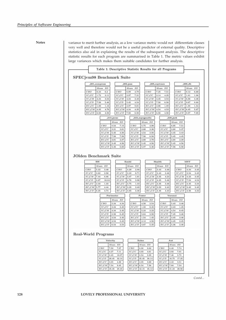
128 LOVELY PROFESSIONAL UNIVERSITY
Principles of Software Engineering
Notes variance to merit further analysis, as a low variance metric would not differentiate classesvery well and therefore would not be a useful predictor of external quality. Descriptivestatistics also aid in explaining the results of the subsequent analysis. The descriptivestatistic results for each program are summarised in Table 1. The metric values exhibitlarge variances which makes them suitable candidates for further analysis.
Table 1: Descriptive Statistic Results for all Programs
Contd...

LOVELY PROFESSIONAL UNIVERSITY 129
Unit 6: Functional Design
NotesPrincipal Component Analysis
Principal Component Analysis (PCA) is used to investigate whether the run- time couplingmetrics are not simply surrogate measures for static CBO. A similar study was carried outby Arisholm et al. using only the Velocity program. The work in this chapter extends theirwork to include fourteen benchmark programs as well as three real-world programs inorder to demonstrate the robustness of these results over a larger range and variety ofprograms. Using the Kaiser criterion to select the number of factors to retain shows thatthe metrics mostly capture three orthogonal dimensions in the sample space formed byall measures. In other words, the coupling is divided along three dimensions for each ofthe programs analysed.
Experiment 2: The Influence of Instruction Coverage
Multiple Regression Analysis
Multiple regression analysis is used to test the hypothesis that instruction coverage of testcases used to evaluate a program has no influence on the relationship between static andrun-time metrics. The two independent variables are thus the static CBO metric and theinstruction coverage measure Ic; each of the six run-time coupling metrics in turn is thenused as the dependent variable.
Results
First, all R values turned out to be positive for each of the programs used in this study. Thismeans that there is a positive correlation between the dependent (run-time metric) andindependent variables CBO and IC. Therefore as the values for CBO and IC increase ordecrease so will the observed value for the run-time metric under consideration.
Questions:
1. Illustrate the function of Principal Component Analysis.
2. Discuss the relationship between Static and Run-time Coupling Metrics.
Source: http://www.cs.nuim.ie/research/pop/papers/AineMitchellPhD.pdf
6.9 Summary
� A design affects the effectiveness of the software that is being built. It fosters the quality ofthe software engineering.
� Abstraction is the elimination of the irrelevant and amplification of the essentials. Anumber of levels of abstraction exist in a modular design.
� Modularity refers to the division of software into separate modules which are differentlynamed and addressed and are integrated later on in order to obtain the completelyfunctional software.
� A top-down design approach starts by identifying the major components of the system,decomposing them into their lower-level components and iterating until the desiredlevel of detail is achieved.
� A bottom-up design approach starts with designing the most basic or primitive componentsand proceeds to higher-level components that use these lower-level components.
� Coupling is the measure of degree of interdependence amongst modules.
� Cohesion is the measure of the degree of functional dependence of modules. A stronglycohesive module implements functionality that interacts little with the other modules.

130 LOVELY PROFESSIONAL UNIVERSITY
Principles of Software Engineering
Notes � A structure chart is a graphical chart used for the purpose of describing and communicatinga model or process within an organization.
� The data flow diagrams should also have some associated documentation. This is necessaryas the diagrams are meant as a visual representation of the way in which information isprocessed.
6.10 Keywords
Abstraction: Abstraction is the elimination of the irrelevant and amplification of the essentials.A number of levels of abstraction exist in a modular design.
Architectural Design: The architectural design defines the relationship between structural elementsof the software, the design patterns and the constraints.
Cohesion: It is the measure of the degree of functional dependence of modules.
Coupling: Coupling is the measure of degree of interdependence amongst modules.
Modularity: Modularity refers to the division of software into separate modules which aredifferently named and addressed and are integrated later on in order to obtain the completelyfunctional software.
Software Design: Software design is a process of problem solving and planning for a softwaresolution.
Software Design Principles: Software design principles represent a set of guidelines that helpsus to avoid having a bad design.
Structure Chart: A structure chart is a graphical chart used for the purpose of describing andcommunicating a model or process within an organization.
6.11 Review Questions
1. Discuss the features of a good design. Also discuss the principles of design.
2. What is abstraction? Discuss the various levels of abstraction.
3. What is modularity? List the important properties of a modular system. Make distinctionbetween top-down design and bottom-up design.
4. Explain the different types of coupling techniques.
5. Describe the concept of cohesion. Also discuss its various forms.
6. How do you communicate organizational ideas within the business environment? Discuss.
7. Illustrate the concept of structure chart with chart.
8. Describe the components of data flow diagram.
9. Explain the concept of data flow diagram with example.
10. A module, that restricts processing to a single sub function, exhibits high cohesion and isviewed with favor by a designer. Comment.
Answers: Self Assessment
1. architectural 2. component-level
3. True 4. False

LOVELY PROFESSIONAL UNIVERSITY 131
Unit 6: Functional Design
Notes5. Abstraction 6. Bottom-up
7. Coupling 8. interconnections
9. Cohesion 10. Sequential
11. structure chart 12. data model
13. Processes 14. Data stores
15. True 16. False
6.12 Further Readings
Books Rajib Mall, Fundamentals of Software Engineering, 2nd Edition, PHI.
Richard Fairpy, Software Engineering Concepts, Tata McGraw Hill, 1997.
R.S. Pressman, Software Engineering – A Practitioner’s Approach, 5th Edition, TataMcGraw Hill Higher education.
Sommerville, Software Engineering, 6th Edition, Pearson Education
Online links http://selab.csuohio.edu/~nsridhar/teaching/fall07/eec521/slides/Lecture08.pdf
http://www.avatto.com/exam/software-engineering-coupling-65.html
http://www.math-cs.gordon.edu/courses/cps122/lectures-2013/Cohesion%20and%20Coupling.pdf
http://www.slideshare.net/arnoldindia/structure-chart
132 LOVELY PROFESSIONAL UNIVERSITY
Principles of Software Engineering
Notes Unit 7: Introduction to Verification
CONTENTS
Objectives
Introduction
7.1 Meaning of Verification
7.1.1 Principles of Software Verification
7.2 Meaning of Metrics
7.2.1 Advantage of Software Metrics
7.2.2 Limitation of Software Metrics
7.2.3 Network Metrics
7.2.4 Stability Metrics
7.2.5 Information Flow Metrics
7.3 Summary
7.4 Keywords
7.5 Review Questions
7.6 Further Readings
Objectives
After studying this unit, you will be able to:
� Understand the meaning of verification
� Understand the meaning of metrics
� Explain network, stability, and information flow metrics
Introduction
Software verification provides objective evidence that the design outputs of a particular phaseof the software development life cycle meet all of the specified requirements for that phase.Software verification looks for consistency, completeness, and correctness of the software andits supporting documentation, as it is being developed, and provides support for a subsequentconclusion that software is validated. Software testing is one of many verification activitiesintended to confirm that software development output meets its input requirements. Otherverification activities include various static and dynamic analyses, code and document inspections,walkthroughs, and other techniques. Software metrics provide a quantitative way to assess thequality of internal product attributes, thereby enabling the software engineer to assess qualitybefore the product is built.
7.1 Meaning of Verification
The terms Verification and Validation are commonly used in software engineering to mean twodifferent types of analysis. The usual definitions are:

LOVELY PROFESSIONAL UNIVERSITY 133
Unit 7: Introduction to Verification
Notes� Validation: Are we building the right system?
� Verification: Are we building the system right?
Verification includes all the activities associated with the producing high quality software:testing, inspection, design analysis, specification analysis, and so on. It is a relatively objectiveprocess, in that if the various products and documents are expressed precisely enough, nosubjective judgements should be needed in order to verify software. Verification is to ensurethat the software being developed implements a specific function. Verification is done againstthe design document. It verifies that the software being developed implements all the functionalityspecified in the design document.
In a traditional phased software lifecycle, verification is often taken to mean checking that theproducts of each phase satisfy the requirements of the previous phase. Validation is relegated tojust the beginning and ending of the project: requirements analysis and acceptance testing. Thisview is common in many software engineering textbooks, and is misguided. It assumes that thecustomer’s requirements can be captured completely at the start of a project, and that thoserequirements will not change while the software is being developed. In practice, the requirementschange throughout a project, partly in reaction to the project itself: the development of newsoftware makes new things possible. Therefore both validation and verification are neededthroughout the lifecycle.
In contrast, validation is an extremely subjective process. It involves making subjectiveassessments of how well the (proposed) system addresses a real-world need. Validation includesactivities such as requirements modelling, prototyping and user evaluation.
Finally, V&V (Verification and Validation) is now regarded as a coherent discipline: “SoftwareV&V is a systems engineering discipline which evaluates the software in a systems context,relative to all system elements of hardware, users, and other software”.
V&V is necessary because the designers and implementers of computer based systems arehuman; they will make errors. These errors will result in undetected faults in delivered systems.Faults can result in dangerous failures causing loss of life, financial loss or property damage.The mission of V&V is therefore to find and correct errors as early as possible in the developmentlife cycle thus preventing the delivery of a faulty product to a customer.
Notes The level of effort applied to V&V is a function of the criticality of the software orsystems product. That is, the risks involved if the system fails.
At one end of the scale the software controlling the shutdown of a nuclear reactor will likely bethoroughly verified and validated by an independent organisation. At the other end of the scale,a website providing a company brochure will likely have no formal verification and validationapplied.
Verification is achieved through:
� Static analysis of documentation (refer figure: Static Verification)
� Evaluation of work products in the context of reviews
� Traceability analysis
� Dynamic testing
� Observing the behaviour software executing on a computer (refer figure: DynamicTesting)

134 LOVELY PROFESSIONAL UNIVERSITY
Principles of Software Engineering
Notes
Source: http://www.chambers.com.au/glossary/verification_validation.php
7.1.1 Principles of Software Verification
Verification can mean the:
� act of reviewing, inspecting, testing, checking, auditing, or otherwise establishing anddocumenting whether items, processes, services or documents conform to specifiedrequirements
� process of evaluating a system or component to determine whether the products of agiven development phase satisfy the conditions imposed at the start of the phase
� formal proof of program correctness
Verification activities include:
� technical reviews, walkthroughs and software inspections;
� checking that software requirements are traceable to user requirements;
� checking that design components are traceable to software
Figure 7.1: Static Verification
Figure 7.2: Dynamic Testing
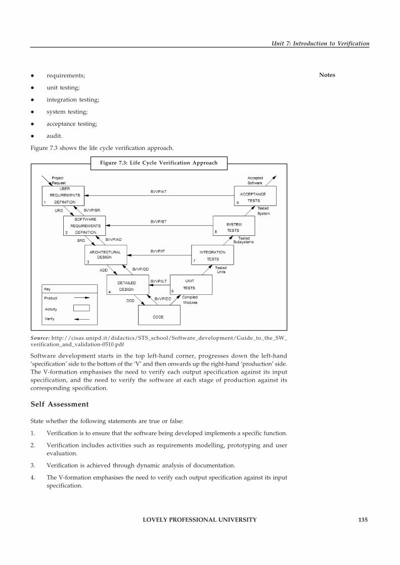
LOVELY PROFESSIONAL UNIVERSITY 135
Unit 7: Introduction to Verification
Notes� requirements;
� unit testing;
� integration testing;
� system testing;
� acceptance testing;
� audit.
Figure 7.3 shows the life cycle verification approach.
Source: http://cisas.unipd.it/didactics/STS_school/Software_development/Guide_to_the_SW_verification_and_validation-0510.pdf
Software development starts in the top left-hand corner, progresses down the left-hand‘specification’ side to the bottom of the ‘V’ and then onwards up the right-hand ‘production’ side.The V-formation emphasises the need to verify each output specification against its inputspecification, and the need to verify the software at each stage of production against itscorresponding specification.
Self Assessment
State whether the following statements are true or false:
1. Verification is to ensure that the software being developed implements a specific function.
2. Verification includes activities such as requirements modelling, prototyping and userevaluation.
3. Verification is achieved through dynamic analysis of documentation.
4. The V-formation emphasises the need to verify each output specification against its inputspecification.
Figure 7.3: Life Cycle Verification Approach

136 LOVELY PROFESSIONAL UNIVERSITY
Principles of Software Engineering
Notes 7.2 Meaning of Metrics
The metric is a quantitative measure of the degree to which a system, component, or processpossesses a given attribute.
Example: Number of errors
Metrics is defined as “a handle or guess about a given attribute.”
Example: Number of errors found per person hours expended.
Metrics provide the insight necessary to create effective analysis and design models, solid code,and thorough tests. To be useful in a real world context, software metric must be simple andcomputable, persuasive, consistent, and objective.
!Caution It should be programming language independent and provide effective feedbackto the software engineer.
Software metrics can be defined as:
“The continuous application of measurement based techniques to the software developmentprocess and its products to supply meaningful and timely management information, togetherwith the use of those techniques to improve that process and its products.”
The most established area of software metrics is cost and size estimation techniques. The predictionof quality levels for software, often in terms of reliability, is another area where softwaremetrics have an important role to play.
Did u know? The use of software metrics to provide quantitative checks on software designis also a well established area.
7.2.1 Advantage of Software Metrics
Software metrics is beneficial:
� In Comparative study of various design methodology of software systems.
� For analysis, comparison and critical study of various programming language with respectto their characteristics.
� In comparing and evaluating capabilities and productivity of people involved in softwaredevelopment.
� In the preparation of software quality specifications.
� In the verification of compliance of software systems requirements and specifications.
� In making inference about the effort to be put in the design and development of thesoftware systems.
� In getting an idea about the complexity of the code.
� In taking decisions regarding further division of complex module is to be done or not.
� In providing guidance to resource manager for their proper utilization.
LOVELY PROFESSIONAL UNIVERSITY 137
Unit 7: Introduction to Verification
Notes� In comparison and making design trade-offs between software development andmaintenance cost.
� In providing feedback to software managers about the progress and quality during variousphases of software development life cycle.
� In allocation of testing resources for testing the code.
7.2.2 Limitation of Software Metrics
� The application of software metrics is not always easy and in some cases it is difficult andcostly.
� The verification and justification of software metrics is based on historical/empirical data
� whose validity is difficult to verify.
� These are useful for managing the software products but not for evaluating performanceof the technical staff.
� The definition and derivation of Software metrics is generally based on assuming whichare not standardized and may depend upon tools available and working environment.
� Most of the predictive models rely on estimates of certain variables which are often notknown exactly.
� Most of the software development models are probabilistic and empirical.
Task Analyse the importance of software metrics.
7.2.3 Network Metrics
Network metrics focus on the structure chart of a system. They attempt to define how “good” thestructure or network is in an effort to quantify the complexity of the call graph. The simpleststructure occurs if the call graph is a tree. As a result, the graph impurity (deviation of the tree)is defined as nodes - edges – 1. In the case of a tree, this metric produces the result zero since thereis always one more node in a tree than edges.
Notes This metric is designed to make you examine nodes that have high coupling andsee if there are ways to reduce this coupling.
7.2.4 Stability Metrics
Stability of a design is a metric that tries to quantify the resistance of a design to the potentialripple effects that are caused by changes in modules. The creators of this metric argue that thehigher the stability of a design, the easier it is to maintain the resulting system. This provides astability value for each particular module.
!Caution The lower the amount of coupling between modules, the higher the stability ofthe overall system.
138 LOVELY PROFESSIONAL UNIVERSITY
Principles of Software Engineering
Notes 7.2.5 Information Flow Metrics
Information flow metrics attempt to define the complexity of a system in terms of the totalamount of information flowing through its modules. Information Flow metrics deal withcomplexity by observing the flow of information among system components or modules.
This metrics is based on the measurement of the information flow among system modules.
Did u know? It is sensitive to the complexity due to interconnection among systemcomponent.
This measure includes complexity of a software module is defined to be the sum of complexitiesof the procedures included in the module. A procedure contributes complexity due to thefollowing two factors.
1. The complexity of the procedure code itself.
2. The complexity due to procedure’s connections to its environment. The effect of the firstfactor has been included through LOC (Lin Of Code) measure. For the quantification ofsecond factor, Henry and Kafura have defined two terms, namely FAN-IN and FAN-OUT.
FAN-IN of a procedure is the number of local flows into that procedure plus the number of datastructures from which this procedure retrieve information. FAN – OUT is the number of localflows from that procedure plus the number of data structures which that procedure updates.
Procedure Complexity = Length * (FAN-IN * FAN-OUT)**2
Where the length is taken as LOC and the term FAN-IN
FAN-OUT represent the total number of input-output combinations for the procedure.
Task Make distinction between FAN-IN and FAN-OUT.
Self Assessment
Fill in the blanks:
5. The …………………… is a quantitative measure of the degree to which a system,component, or process possesses a given attribute.
6. …………………… metrics attempt to define how “good” the structure or network is in aneffort to quantify the complexity of the call graph.
7. …………………… of a design is a metric that tries to quantify the resistance of a design tothe potential ripple effects that are caused by changes in modules.
8. …………………… metrics attempt to define the complexity of a system in terms of thetotal amount of information flowing through its modules.
9. …………………… of a procedure is the number of local flows into that procedure plus thenumber of data structures from which this procedure retrieve information.
10. …………………… represent the total number of input-output combinations for theprocedure.
LOVELY PROFESSIONAL UNIVERSITY 139
Unit 7: Introduction to Verification
Notes7.3 Summary
� Verification includes all the activities associated with the producing high quality software:testing, inspection, design analysis, specification analysis, and so on.
� In a traditional phased software lifecycle, verification is often taken to mean checking thatthe products of each phase satisfy the requirements of the previous phase.
� Validation involves making subjective assessments of how well the (proposed) systemaddresses a real-world need.
� Software V&V is a systems engineering discipline which evaluates the software in asystems context, relative to all system elements of hardware, users, and other software.
� The metric is a quantitative measure of the degree to which a system, component, orprocess possesses a given attribute.
� Network metrics focus on the structure chart of a system. They attempt to define how“good” the structure or network is in an effort to quantify the complexity of the call graph.
� Stability of a design is a metric that tries to quantify the resistance of a design to thepotential ripple effects that are caused by changes in modules.
� Information flow metrics attempt to define the complexity of a system in terms of the totalamount of information flowing through its modules.
7.4 Keywords
FAN-IN: FAN-IN of a procedure is the number of local flows into that procedure plus thenumber of data structures from which this procedure retrieve information.
FAN-OUT: FAN-OUT is the number of local flows from that procedure plus the number of datastructures which that procedure updates.
Information Flow Metrics: Information flow metrics attempt to define the complexity of asystem in terms of the total amount of information flowing through its modules.
Metric: The metric is a quantitative measure of the degree to which a system, component, orprocess possesses a given attribute.
Network Metrics: Network metrics attempt to define how “good” the structure or network is inan effort to quantify the complexity of the call graph.
Stability Metric: Stability of a design is a metric that tries to quantify the resistance of a designto the potential ripple effects that are caused by changes in modules.
V&V: Software V&V is a systems engineering discipline which evaluates the software in asystems context, relative to all system elements of hardware, users, and other software.
Verification: Verification is an act of reviewing, inspecting, testing, checking, auditing, orotherwise establishing and documenting whether items, processes, services or documentsconform to specified requirements.
7.5 Review Questions
1. What do you mean by verification? Illustrate with example.
2. Describe how can you achieve verification through Static Verification.

140 LOVELY PROFESSIONAL UNIVERSITY
Principles of Software Engineering
Notes 3. Discuss the principles of verification.
4. Explain the life cycle of verification approach.
5. Describe the concept of software metrics.
6. Discuss the advantages and disadvantages of software metrics.
7. Explain the functions of network metrics.
8. The higher the stability of a design, the easier it is to maintain the resulting system.Comment.
9. Discuss the concept of information flow metrics.
10. Compare and contrast network metrics and information flow metrics.
Answers: Self Assessment
1. True 2. False
3. False 4. True
5. metric 6. Network
7. Stability 8. Information flow
9. FAN-IN 10. FAN-OUT
7.6 Further Readings
Books Rajib Mall, Fundamentals of Software Engineering, 2nd Edition, PHI.
Richard Fairpy, Software Engineering Concepts, Tata McGraw Hill, 1997.
R.S. Pressman, Software Engineering – A Practitioner’s Approach, 5th Edition, TataMcGraw Hill Higher education.
Sommerville, Software Engineering, 6th Edition, Pearson Education
Online links http://www.ijcem.org/papers12011/12011_14.pdf
http://www.slideshare.net/koolkampus/verification-and-validation-in-software-engineering-se19
http://ti.arc.nasa.gov/tech/rse/publications/vnv/
LOVELY PROFESSIONAL UNIVERSITY 141
Unit 8: Detailed Design
NotesUnit 8: Detailed Design
CONTENTS
Objectives
Introduction
8.1 Concept of Detailed Design
8.1.1 Design Documentation
8.2 Process Design Language
8.3 Logic and Algorithm Design
8.3.1 Verification of Logic and Algorithm Design
8.4 Summary
8.5 Keywords
8.6 Review Questions
8.7 Further Readings
Objectives
After studying this unit, you will be able to:
� Discuss the concept of detailed design
� Explain process design language
� Describe the concept of logic/algorithm design
� Discuss verification of logic/algorithm design
Introduction
Detailed design of the system is the last design activity before implementation begins. Thehardest design problems must be addressed by the detailed design or the design is not complete.The detailed design is still an abstraction as compared to source code, but should be detailedenough to ensure that translation to source is a precise mapping instead of a rough interpretation.
The detailed design should represent the system design in a variety of views where each viewuses a different modeling technique. By using a variety of views, different parts of the systemcan be made clearer by different views. Some views are better at elaborating a systems stateswhereas other views are better at showing how data flows within the system. Other views arebetter at showing how different system entities relate to each through class taxonomies forsystems that are designed using an object-oriented approach. A template for detailed designwould not be of much use since each detailed design is likely to be unique and quite differentfrom other designs.
8.1 Concept of Detailed Design
Once high-level design is done, you have:
� a graphical representation of the structure of your software system

142 LOVELY PROFESSIONAL UNIVERSITY
Principles of Software Engineering
Notes � a document that defines high-level details of each module in your system, including
� a module’s interface (including input and output data types)
� notes on possible algorithms or data structures the module can use to meet itsresponsibilities a list of any non-functional requirements that might impact the module.
After high-level design, a designer’s focus shifts to low-level design
� Each module’s responsibilities should be specified as precisely as possible
� Constraints on the use of its interface should be specified
� pre- and post-conditions can be identified
� module-wide invariants can be specified
� internal data structures and algorithms can be suggested.
A designer must exhibit caution, however, to not over specify a design
� as a result, we do not want to express a module’s detailed design using a programminglanguage
� you would naturally end up implementing the module perhaps unnecessarily constrainingthe approaches a developer would use to accomplish the same job
� nor do we (necessarily) want to use only natural language text to specify a module’sdetailed design
� natural language text slips too easily towards ambiguity
8.1.1 Design Documentation
The design specification contains various aspects of the design model and is completed as thedesigner improves his software representation. At first, the design specification derives itsscope from System specification and the analysis model.
At the next level data design is specified. The data design includes database structure, externalfile structure, internal data structures and reference connecting data objects to files.
The design specification contains requirements cross reference represented as a simple matrix.
Did u know? The purpose of this matrix is:
(i) to ensure that the design includes all the requirements, and
(ii) to indicate the critical components for the implementation purpose.
The design document may also contain the first stage of test documentation. After the programstructure and the interfaces have been established, guidelines to test individual and integratedmodules are developed.
Design constraints such as limited physical memory or special external interface can causespecial design techniques to evolve which in turn will lead to changes in software package.
The final section of the design specification contains supplementary data such as algorithmdescription, tabular data, excerpts from other documents, etc.
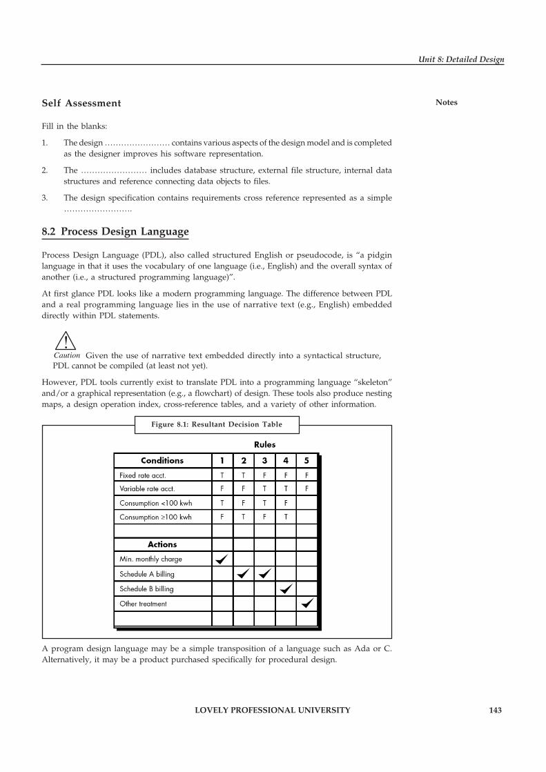
LOVELY PROFESSIONAL UNIVERSITY 143
Unit 8: Detailed Design
NotesSelf Assessment
Fill in the blanks:
1. The design …………………… contains various aspects of the design model and is completedas the designer improves his software representation.
2. The …………………… includes database structure, external file structure, internal datastructures and reference connecting data objects to files.
3. The design specification contains requirements cross reference represented as a simple…………………….
8.2 Process Design Language
Process Design Language (PDL), also called structured English or pseudocode, is “a pidginlanguage in that it uses the vocabulary of one language (i.e., English) and the overall syntax ofanother (i.e., a structured programming language)”.
At first glance PDL looks like a modern programming language. The difference between PDLand a real programming language lies in the use of narrative text (e.g., English) embeddeddirectly within PDL statements.
!Caution Given the use of narrative text embedded directly into a syntactical structure,PDL cannot be compiled (at least not yet).
However, PDL tools currently exist to translate PDL into a programming language “skeleton”and/or a graphical representation (e.g., a flowchart) of design. These tools also produce nestingmaps, a design operation index, cross-reference tables, and a variety of other information.
A program design language may be a simple transposition of a language such as Ada or C.Alternatively, it may be a product purchased specifically for procedural design.
Figure 8.1: Resultant Decision Table
144 LOVELY PROFESSIONAL UNIVERSITY
Principles of Software Engineering
Notes Regardless of origin, a design language should have the following characteristics:
� A fixed syntax of keywords that provide for all structured constructs, data declaration, andmodularity characteristics.
� A free syntax of natural language that describes processing features.
� Data declaration facilities that should include both simple (scalar, array) and complex(linked list or tree) data structures.
� Subprogram definition and calling techniques that support various modes of interfacedescription.
A basic PDL syntax should include constructs for subprogram definition, interface description,data declaration, techniques for block structuring, condition constructs, repetition constructs,and I/O constructs.
Notes It should be noted that PDL can be extended to include keywords for multi-taskingand/or concurrent processing, interrupt handling, inter-process synchronization, and manyother features.
The application design for which PDL is to be used should dictate the final form for the designlanguage.
Example: To illustrate the use of PDL, we present an example of a procedural design forthe SafeHome security system software. The system monitors alarms for fire, smoke, burglar,water, and temperature (e.g., furnace breaks while homeowner is away during winter) andproduces an alarm bell and calls a monitoring service, generating a voice-synthesized message.In the PDL that follows, we illustrate some of the important constructs noted in earlier sections.
Recall that PDL is not a programming language. The designer can adapt as required withoutworry of syntax errors. However, the design for the monitoring software would have to bereviewed (do you see any problems?) and further refined before code could be written. Thefollowing PDL defines an elaboration of the procedural design for the security monitorcomponent.
PROCEDURE security.monitor;
INTERFACE RETURNS system.status;
TYPE signal IS STRUCTURE DEFINED
name IS STRING LENGTH VAR;
address IS HEX device location;
bound.value IS upper bound SCALAR: messageIS STRING LENGTH VAR: END signal TYPE:
TYPE system.status IS BIT (4):TYPE alarm.type DEFINED
smoke.alarm IS INSTANCE OF signal:fire.alarm IS INSTANCE OF signal:water.alarm IS INSTANCE OF signal:temp.alarm IS INSTANCE OF signal:burglar.alarm IS INSTANCE OF signal:
TYPE phone.number IS area code + 7-digitnumber: o
oo
LOVELY PROFESSIONAL UNIVERSITY 145
Unit 8: Detailed Design
Notesinitialize all system ports and reset allhardware: CASE OF control.panel.switches(cps):
WHEN cps = "test" SELECTCALL alarm PROCEDURE WITH "on" for test.time in seconds:
WHEN cps = "alarm-off" SELECTCALL alarm PROCEDURE WITH "off": WHEN cps =
"new.bound.temp" SELECT CALL keypad.inputPROCEDURE:WHEN cps = "burglar.alarm.off" SELECT deactivate signal[burglar.alarm]: oooDEFAULT none: ENDCASE
REPEAT UNTIL activate.switch is turned offreset all signal.values and switches:DO FOR alarm.type = smoke, fire, water, temp, burglar:
READ address [alarm.type] signal.value:IF signal.value > bound [alarm.type]THEN phone.message = message [alarm.type]:
set alarm.bell to "on" for alarm.timeseconds:PARBEGINCALL alarm PROCEDURE WITH "on", alarm.time in seconds:CALL phone PROCEDURE WITH message [alarm.type],
phone.number:ENDPAR
ELSE skip ENDIFENDFOR
ENDREPEND security.monitor
Note that the designer for the security.monitor component has used a new construct PARBEGIN .. . ENDPAR that specifies a parallel block. All tasks specified within the PARBEGIN block areexecuted in parallel. In this case, implementation details are not considered.
Task Make distinction between PDL and a real programming language.
Self Assessment
Fill in the blanks:
4. …………………… is “a pidgin language in that it uses the vocabulary of one language andthe overall syntax of another.
5. PDL …………………… currently exist to translate PDL into a programming language“skeleton” and/or a graphical representation of design.
6. A basic PDL …………………… should include constructs for subprogram definition,interface description, data declaration, etc.
8.3 Logic and Algorithm Design
Logic and Algorithms design covers Algorithmic and Computational Logic, and is the scientificfoundation for constructing robust, efficient, and intelligent software applications based onmathematically sound solutions. Large data sets and basically hard problems are the two crucialaspects when designing efficient software. Usually, the naive algorithm or data structure cansuffices for resolving minor problems. On a personal computer, a simple search engine caneasily index the contents of a drive, but indexing the web is much more problematic. Likewise,

146 LOVELY PROFESSIONAL UNIVERSITY
Principles of Software Engineering
Notes an autonomous robot can design its actions optimally by an exhaustive state space search onlyif the number of possible actions and states is very inadequate. Consequently, more advancedmethods are required to resolve these difficulties. Often some degree of intelligence is requiredin addition to efficiency in software applications for complex problems. Intelligence impliesthat the software is capable to collect and categorise knowledge, learn from experiences, dological reasoning, and communicate and negotiate with other software applications.
Did u know? The scientific foundation for such applications comprises of logic-based AIand computational logic.
Algorithmic: An algorithm is a procedure to accomplish a specific task. An algorithm is the ideabehind any reasonable computer program. Algorithmic is the systematic development of efficientalgorithms and therefore has pivotal influence on the effective development of reliable andresource-conserving technology. An algorithmic problem is specied by describing the completeset of instances it must work on and of its output after running on one of these instances. Thisdistinction, between a problem and an instance of a problem, is fundamental.
Computational Logic: Computational logic is the use of logic to perform or reason aboutcomputation. It bears a similar relationship to computer science and engineering as mathematicallogic bears to mathematics and as philosophical logic bears to philosophy. It is synonymouswith “logic in computer science”. Computational Logic plays an important role in many areasof computer science, including verification of hardware and software, programming languages,databases and Artificial Intelligence.
In detailed design the basic aim is to identify the logic for the various modules that have beenstated during system design. Stating the logic will necessitate developing an algorithm that willimplement the given specifications. Now we contemplate certain principles for designingalgorithms or logic that will apply the given conditions.
The term algorithm is relatively general and is applicable to wide-ranging areas. We can considerfor software an algorithm to be an explicit procedure for solving a problem. A procedure is afinite sequence of well-defined steps or operations, each of which requires a memory time tocomplete and finite amount of. In this explanation we see that termination is a vital property ofprocedures. From now, we will use algorithms, logic, and procedures interchangeably.
Algorithm is a step-by-step finite sequence of instruction, to solve a well-defined computationalproblem. That is, in practice to solve any complex real life problems; first we have to define theproblems. Second step is to design the algorithm to solve that problem. Writing and executingprograms and then optimizing them may be effective for small programs. Optimization of aprogram is directly concerned with algorithm design. But for a large program, each part of theprogram must be well organized before writing the program. There are few steps of refinementinvolved when a problem is converted to program; this method is called step-wise refinementmethod. There are two approaches for algorithm design; they are top-down and bottom-upalgorithm design.
!Caution Once the algorithm is designed, its correctness should be verified.
We can write an informal algorithm, if we have an appropriate mathematical model for aproblem. The initial version of the algorithm will contain general statements, i.e.,; informalinstructions. Then we convert this informal algorithm to formal algorithm, that is, more definiteinstructions by applying any programming language syntax and semantics partially. Finally aprogram can be developed by converting the formal algorithm by a programming languagemanual. From the above discussion we have understood that there are several steps to reach a
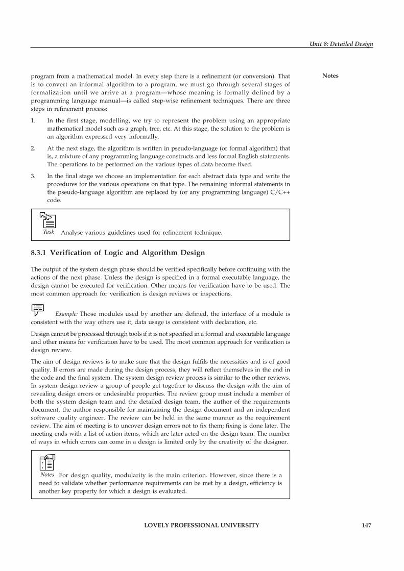
LOVELY PROFESSIONAL UNIVERSITY 147
Unit 8: Detailed Design
Notesprogram from a mathematical model. In every step there is a refinement (or conversion). Thatis to convert an informal algorithm to a program, we must go through several stages offormalization until we arrive at a program—whose meaning is formally defined by aprogramming language manual—is called step-wise refinement techniques. There are threesteps in refinement process:
1. In the first stage, modelling, we try to represent the problem using an appropriatemathematical model such as a graph, tree, etc. At this stage, the solution to the problem isan algorithm expressed very informally.
2. At the next stage, the algorithm is written in pseudo-language (or formal algorithm) thatis, a mixture of any programming language constructs and less formal English statements.The operations to be performed on the various types of data become fixed.
3. In the final stage we choose an implementation for each abstract data type and write theprocedures for the various operations on that type. The remaining informal statements inthe pseudo-language algorithm are replaced by (or any programming language) C/C++code.
Task Analyse various guidelines used for refinement technique.
8.3.1 Verification of Logic and Algorithm Design
The output of the system design phase should be verified specifically before continuing with theactions of the next phase. Unless the design is specified in a formal executable language, thedesign cannot be executed for verification. Other means for verification have to be used. Themost common approach for verification is design reviews or inspections.
Example: Those modules used by another are defined, the interface of a module isconsistent with the way others use it, data usage is consistent with declaration, etc.
Design cannot be processed through tools if it is not specified in a formal and executable languageand other means for verification have to be used. The most common approach for verification isdesign review.
The aim of design reviews is to make sure that the design fulfils the necessities and is of goodquality. If errors are made during the design process, they will reflect themselves in the end inthe code and the final system. The system design review process is similar to the other reviews.In system design review a group of people get together to discuss the design with the aim ofrevealing design errors or undesirable properties. The review group must include a member ofboth the system design team and the detailed design team, the author of the requirementsdocument, the author responsible for maintaining the design document and an independentsoftware quality engineer. The review can be held in the same manner as the requirementreview. The aim of meeting is to uncover design errors not to fix them; fixing is done later. Themeeting ends with a list of action items, which are later acted on the design team. The numberof ways in which errors can come in a design is limited only by the creativity of the designer.
Notes For design quality, modularity is the main criterion. However, since there is aneed to validate whether performance requirements can be met by a design, efficiency isanother key property for which a design is evaluated.

148 LOVELY PROFESSIONAL UNIVERSITY
Principles of Software Engineering
Notes Self Assessment
Fill in the blanks:
7. …………………… constitutes the scientific foundation for reasoning about resources usedin computing such as time and space.
8. …………………… is the study of logic and logical methods within computer science.
9. …………………… is the study of valid inferences, and in computational logic it is studieshow to automate such inferences on a computer.
10. The basic goal in …………………… is to specify the logic for the different modules thathave been specified during system design.
11. The step-wise …………………… technique breaks the logic design problem into a seriesof steps, so that the development can be done gradually.
12. The purpose of design …………………… is to ensure that the design satisfies therequirements and is of good quality.
8.4 Summary
� The design specification contains various aspects of the design model and is completed asthe designer improves his software representation.
� The data design includes database structure, external file structure, internal data structuresand reference connecting data objects to files.
� Process Design Language (PDL), also called structured English or pseudocode, is “a pidginlanguage in that it uses the vocabulary of one language (i.e., English) and the overallsyntax of another (i.e., a structured programming language)”.
� A basic PDL syntax should include constructs for subprogram definition, interfacedescription, data declaration, techniques for block structuring, condition constructs,repetition constructs, and I/O constructs.
� The application design for which PDL is to be used should dictate the final form for thedesign language.
� A program design language may be a simple transposition of a language such as Ada or C.
� Computational logic is the study of logic and logical methods within computer science.
� The purpose of design reviews is to ensure that the design satisfies the requirements andis of good quality.
8.5 Keywords
Algorithmic: Algorithmic is the systematic development of efficient algorithms and thereforehas pivotal influence on the effective development of reliable and resource-conservingtechnology.
Computational Logic: It is the study of logic and logical methods within computer science.
Logic: Logic is the study of valid inferences, and in computational logic it is studies how toautomate such inferences on a computer.
PDL: Process Design Language (PDL), also called structured English or pseudocode, is “a pidginlanguage in that it uses the vocabulary of one language and the overall syntax of another.

LOVELY PROFESSIONAL UNIVERSITY 149
Unit 8: Detailed Design
Notes8.6 Review Questions
1. Explain the concept of detailed design.
2. What is the purpose of the matrix included in design specification?
3. What is Process Design Language (PDL)? Discuss.
4. Illustrate the concept of Process Design Language (PDL) with example.
5. Discuss the characteristics of Process Design Language (PDL).
6. Discuss the format and semantics for some of these PDL constructs.
7. Explain the use of Algorithms and Logic design for constructing efficient, and intelligentsoftware application.
8. Describe the goal of detailed design.
9. Discuss the verification of logic and algorithm design.
10. Given the use of narrative text embedded directly into a syntactical structure, PDL cannotbe compiled. Comment.
Answers: Self Assessment
1. specification 2. data design
3. matrix 4. Process design language (PDL)
5. tools 6. Syntax
7. Algorithmic 8. Computational logic
9. Logic 10. detailed design
11. refinement 12. reviews
8.7 Further Readings
Books Rajib Mall, Fundamentals of Software Engineering, 2nd Edition, PHI.
Richard Fairpy, Software Engineering Concepts, Tata McGraw Hill, 1997.
R.S. Pressman, Software Engineering – A Practitioner’s Approach, 5th Edition, TataMcGraw Hill Higher education.
Sommerville, Software Engineering, 6th Edition, Pearson Education
Online links http://www.cs.colorado.edu/~kena/classes/5828/s07/lectures/21/lecture21.pdf
http://wwwis.win.tue.nl/2R690/projects/spingrid/ddd.pdf
http://programmers.stackexchange.com/questions/19592/what-is-detailed-design-what-are-the-advantage-disadvantages-using-it
150 LOVELY PROFESSIONAL UNIVERSITY
Principles of Software Engineering
Notes Unit 9: Metrics
CONTENTS
Objectives
Introduction
9.1 Cyclomatic Complexity
9.1.1 Variations: CC, CC2 and CC3
9.1.2 Values of Cyclomatic Complexity
9.1.3 Cyclomatic Complexity and Select Case
9.1.4 Total Cyclomatic Complexity (TCC)
9.1.5 DECDENS (Decision Density)
9.2 Data Binding Metrics
9.3 Cohesion Metrics
9.3.1 The idea of the cohesive class
9.3.2 Lack of Cohesion of Methods (LCOM)
9.3.3 Tight and Loose Class Cohesion (TCC and LCC)
9.3.4 Validity of Cohesion
9.4 Summary
9.5 Keywords
9.6 Review Questions
9.7 Further Readings
Objectives
After studying this unit, you will be able to:
� Discuss the concept of cyclomatic complexity
� Explain data binding metrics
� Discuss cohesion metrics
Introduction
Metrics are meaningful only if they have been examined for statistical validity. The controlchart is a simple method for accomplishing this and at the same time examining the variationand location of metrics results. Measurement results in cultural change. Data collection, metricscomputation, and metrics analysis are the three steps that must be implemented to begin ametrics program. In general, a goal-driven approach helps an organization focus on the rightmetrics for its business. By creating a metrics baseline a database containing process and productmeasurements software engineers and their managers can gain better insight into the work thatthey do and the product that they produce. An indicator is a metric or combination of metricsthat provide insight into the software process, a software project, or the product itself. An

LOVELY PROFESSIONAL UNIVERSITY 151
Unit 9: Metrics
Notesindicator provides insight that enables the project manager or software engineers to adjust theprocess, the project, or the process to make things better.
9.1 Cyclomatic Complexity
It is invented by Thomas McCabe (1974) to measure the complexity of a program’s conditionallogic. It counts the number of decisions in the program, under the assumption that decisions aredifficult for people. It makes assumptions about decision-counting rules and linear dependenceof the total count to complexity.
Cyclomatic complexity, also known as V(G) or the graph theoretic number, is probably themost widely used complexity metric in software engineering. Defined by Thomas McCabe, it’seasy to understand and calculate, and it gives useful results. This metric considers the controllogic in a procedure. It’s a measure of structural complexity. Low complexity is desirable.
How to calculate cyclomatic complexity?
CC = Number of decisions + 1
The cyclomatic complexity of a procedure equals the number of decisions plus one. What aredecisions? Decisions are caused by conditional statements. In Visual Basic they are If..ElseIf..Else,Case, For..Next, Until, While, Catch and When. In order to get CC, one simply counts theconditional statements. A multi-way decision, the Select Case block, typical counts as severalconditional statements. The decisions counted for each statement or construct are listed below.
Construct Decisions Reasoning
If..Then +1 An “If statement” is a single decision.
ElseIf..Then +1 ElseIf adds a new decision.
Else 0 Else does not cause a new decision. The decision is at the If.
# If..#ElseIf..#Else 0 Conditional compilation adds no run-time decisions.
Select Case 0 Select Case initiates the following Case branches, but does not add a decision alone.
Case +1 Each Case branch adds a new decision.
Case Else 0 Case Else does not cause a new decision. The decisions were made at the other Cases.
For [Each] .. Next +1 There is a decision at the For statement.
Do While|Until +1 There is a decision at the start of the Do..Loop.
Loop While|Until +1 There is a decision at the end of the Do..Loop.
Do..Loop alone 0 There is no decision in an unconditional Do..Loop without While or Until.*
While +1 There is a decision at the start of the While..Wend or While..End While loop.
Catch +1 Each Catch branch adds a new conditional path of execution. Even though a Catch can be either conditional (catches specific exceptions) or unconditional (catches all exceptions), we treat all of them the same way.*
Catch..When +2 The When condition adds a second decision.*
* Rules marked with an asterisk were added into Project Analyzer v8.0. Previous versions did not takethese rules into account.
Table 9.1: Decisions Counted for each Statement

152 LOVELY PROFESSIONAL UNIVERSITY
Principles of Software Engineering
Notes The minimum limit for cyclomatic complexity is 1. This happens with a procedure having nodecisions at all. There is no maximum value since a procedure can have any number of decisions.
Notes
� A Case branch can cover several alternative values or ranges, such as Case 1, 2, 5 to10. As they introduce no additional branches to decide on, they do not increasecyclomatic complexity either.
� Cyclomatic complexity does not consider if any decisions actually happen at run-time. A conditional statement can be unconditional in reality. This happens withconstant decisions such as If True Then. This kind of an “unconditional condition”counts as a regular decision in cyclomatic complexity, even when there is only onepath to take, really.
� Multiple exits do not increase complexity. A procedure with a single exit is ascomplex as one with multiple exits.
� Exit statements (Exit Do, Exit Sub, Return, End, and similar) do not increase cyclomaticcomplexity. They are not decisions, but jumps. Complexity-wise, exit statementsare similar to GoTo statements, with the target being either end-of-structure or end-of-procedure.
� Yield statements do not increase cyclomatic complexity. Yield, new in VB2012, islike a procedure call, but backwards, back to the caller procedure. Executionpotentially continues with the statement following Yield. If it doesn’t, Yield is just aspecial exit, which doesn’t increase cyclomatic complexity either.
9.1.1 Variations: CC, CC2 and CC3
Cyclomatic complexity comes in a couple of variations as to what exactly counts as a decision.Project Analyzer supports three alternative cyclomatic complexity metrics. CC is the basicversion. CC2 and CC3 use slightly different rules.
CC does not count Boolean operators such as And and Or. Boolean operators add internalcomplexity to the decisions, but they are not counted in CC. CC and CC3 are similar what comesto Booleans, but CC2 is different.
CC2 Cyclomatic Complexity with Booleans (“Extended Cyclomatic Complexity”)
CC2 = CC + Boolean operators
CC2 extends cyclomatic complexity by including Boolean operators in the decision count.Whenever a Boolean operator (And, Or, Xor, Eqv, AndAlso, OrElse) is found within a conditionalstatement, CC2 increases by one. The statements considered are: If, ElseIf, Select, Case, Until,While, When.
The reasoning behind CC2 is that a Boolean operator increases the internal complexity of adecision. CC2 counts the “real” number of decisions, regardless of whether they appear as asingle conditional statement or split into several statements. Instead of using Boolean operatorsto combine decisions into one (x = 1 And y = 2), you could as well split the decisions into severalsub-conditions (If x = 1 Then If y = 2 Then). CC2 is immune to this kind of restructuring, whichmight be well justified to make the code more readable. On the other hand, one can decrease CCsimply by combining decisions with Boolean operators, which may not make sense.

LOVELY PROFESSIONAL UNIVERSITY 153
Unit 9: Metrics
NotesIncluding Boolean operators in cyclomatic complexity was originally suggested by ThomasMcCabe. In this sense, both CC and CC2 are “original” cyclomatic complexity measures.
Alternative names: CC2 is also known as ECC extended cyclomatic complexity or strict cyclomaticcomplexity.
Notes A Case branch can cover several alternative values or ranges, such as Case 1, 2, 5 to10. These are not counted in CC2, even if they add internal complexity to the decision,quite the same way as the Or operator does in an If statement. A Case with severalalternatives (Case 1, 2, 3) is usually simpler than the same decision as an If statement (If x= 1 Or x = 2 Or x = 3 Then). A Case like this will also yield a lower CC2 than the respectiveIf. Splitting the If statement into successive If..ElseIf branches will keep CC2 unmodified,but rewriting it as a single Case will decrease CC2.
CC3 Cyclomatic Complexity without Cases (“Modified Cyclomatic Complexity”)
CC3 = CC where each Select block counts as one
CC3 equals the regular CC metric, but each Select Case block is counted as one branch, not asmultiple branches. In this variation, a Select Case is treated as if it were a single big decision.This leads to considerably lower complexity values for procedures with large Select Casestatements. In many cases, Select Case blocks are simple enough to consider as one decision,which justifies the use of CC3.
Alternative Name: CC3 is sometimes called modified cyclomatic complexity.
Summary of cyclomatic complexity metrics is shown in the table.
Metric Name Boolean operators
Select Case Alternative name
CC Cyclomatic complexity Not counted +1 for each Case branch
Regular cyclomatic complexity
CC2 Cyclomatic complexity with Booleans
+1 for each Boolean
+1 for each Case branch
Extended or strict cyclomatic complexity
CC3 Cyclomatic complexity without Cases
Not counted +1 for an entire Select Case
Modified cyclomatic complexity
CC, CC2 or CC3—which one to use? This is your decision. Pick up the one that suits your usebest. CC and CC2 are “original” metrics and probably more widely used than CC3. The numericvalues are, in increasing order: CC3 (lowest), CC (middle) and CC2 (highest). In a sense, CC2 isthe most pessimistic metric. All of them are heavily correlated, so you can achieve good resultswith any of them.
9.1.2 Values of Cyclomatic Complexity
A high cyclomatic complexity denotes a complex procedure that’s hard to understand, test andmaintain. There’s a relationship between cyclomatic complexity and the “risk” in a procedure.
Table 9.2: Summary of Cyclomatic Complexity Metrics
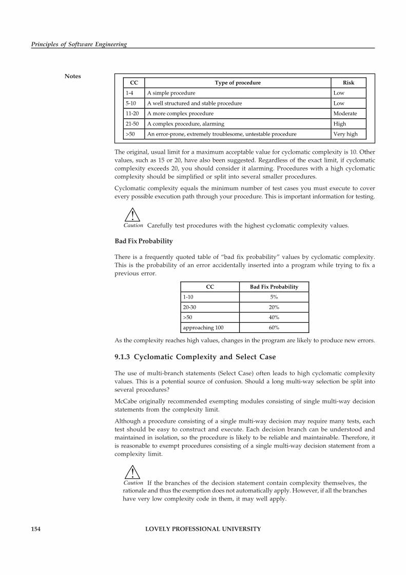
154 LOVELY PROFESSIONAL UNIVERSITY
Principles of Software Engineering
NotesCC Type of procedure Risk
1-4 A simple procedure Low
5-10 A well structured and stable procedure Low
11-20 A more complex procedure Moderate
21-50 A complex procedure, alarming High
>50 An error-prone, extremely troublesome, untestable procedure Very high
The original, usual limit for a maximum acceptable value for cyclomatic complexity is 10. Othervalues, such as 15 or 20, have also been suggested. Regardless of the exact limit, if cyclomaticcomplexity exceeds 20, you should consider it alarming. Procedures with a high cyclomaticcomplexity should be simplified or split into several smaller procedures.
Cyclomatic complexity equals the minimum number of test cases you must execute to coverevery possible execution path through your procedure. This is important information for testing.
!Caution Carefully test procedures with the highest cyclomatic complexity values.
Bad Fix Probability
There is a frequently quoted table of “bad fix probability” values by cyclomatic complexity.This is the probability of an error accidentally inserted into a program while trying to fix aprevious error.
CC Bad Fix Probability
1-10 5%
20-30 20%
>50 40%
approaching 100 60%
As the complexity reaches high values, changes in the program are likely to produce new errors.
9.1.3 Cyclomatic Complexity and Select Case
The use of multi-branch statements (Select Case) often leads to high cyclomatic complexityvalues. This is a potential source of confusion. Should a long multi-way selection be split intoseveral procedures?
McCabe originally recommended exempting modules consisting of single multi-way decisionstatements from the complexity limit.
Although a procedure consisting of a single multi-way decision may require many tests, eachtest should be easy to construct and execute. Each decision branch can be understood andmaintained in isolation, so the procedure is likely to be reliable and maintainable. Therefore, itis reasonable to exempt procedures consisting of a single multi-way decision statement from acomplexity limit.
!Caution If the branches of the decision statement contain complexity themselves, therationale and thus the exemption does not automatically apply. However, if all the brancheshave very low complexity code in them, it may well apply.
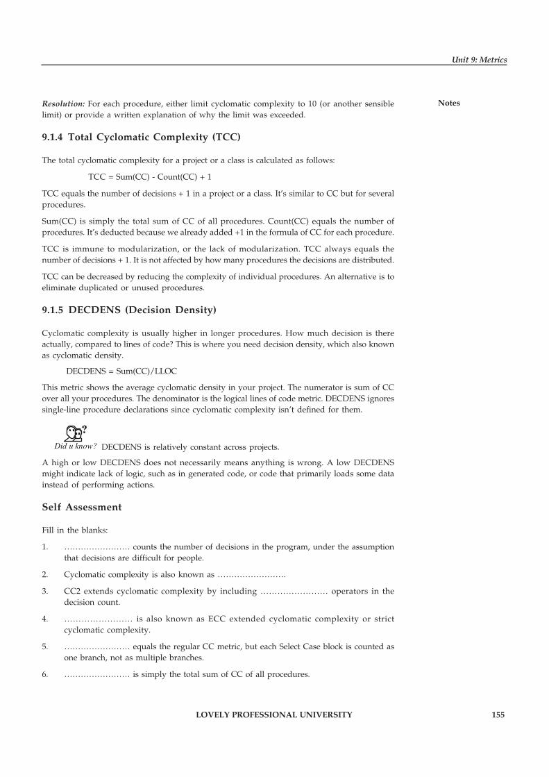
LOVELY PROFESSIONAL UNIVERSITY 155
Unit 9: Metrics
NotesResolution: For each procedure, either limit cyclomatic complexity to 10 (or another sensiblelimit) or provide a written explanation of why the limit was exceeded.
9.1.4 Total Cyclomatic Complexity (TCC)
The total cyclomatic complexity for a project or a class is calculated as follows:
TCC = Sum(CC) - Count(CC) + 1
TCC equals the number of decisions + 1 in a project or a class. It’s similar to CC but for severalprocedures.
Sum(CC) is simply the total sum of CC of all procedures. Count(CC) equals the number ofprocedures. It’s deducted because we already added +1 in the formula of CC for each procedure.
TCC is immune to modularization, or the lack of modularization. TCC always equals thenumber of decisions + 1. It is not affected by how many procedures the decisions are distributed.
TCC can be decreased by reducing the complexity of individual procedures. An alternative is toeliminate duplicated or unused procedures.
9.1.5 DECDENS (Decision Density)
Cyclomatic complexity is usually higher in longer procedures. How much decision is thereactually, compared to lines of code? This is where you need decision density, which also knownas cyclomatic density.
DECDENS = Sum(CC)/LLOC
This metric shows the average cyclomatic density in your project. The numerator is sum of CCover all your procedures. The denominator is the logical lines of code metric. DECDENS ignoressingle-line procedure declarations since cyclomatic complexity isn’t defined for them.
Did u know? DECDENS is relatively constant across projects.
A high or low DECDENS does not necessarily means anything is wrong. A low DECDENSmight indicate lack of logic, such as in generated code, or code that primarily loads some datainstead of performing actions.
Self Assessment
Fill in the blanks:
1. …………………… counts the number of decisions in the program, under the assumptionthat decisions are difficult for people.
2. Cyclomatic complexity is also known as …………………….
3. CC2 extends cyclomatic complexity by including …………………… operators in thedecision count.
4. …………………… is also known as ECC extended cyclomatic complexity or strictcyclomatic complexity.
5. …………………… equals the regular CC metric, but each Select Case block is counted asone branch, not as multiple branches.
6. …………………… is simply the total sum of CC of all procedures.

156 LOVELY PROFESSIONAL UNIVERSITY
Principles of Software Engineering
Notes 9.2 Data Binding Metrics
It is a metric to capture the strength of coupling between modules in a software system. It isdefined by triplet (p,x,q) where p and q are modules and X is variable within scope of both pand q.
Different types of data binding metrics are:
� Potential Data Binding: In case of potential data binding, X is declared in both, but doesnot check to see if accessed. It reflects possibility that p and q might communicate throughthe shared variable.
� Used Data Binding: It is a potential data binding where p and q use X. It is harder tocompute than potential data binding and requires more information about internal logicof module.
� Actual Data Binding: It is used data binding where p assigns value to x and q references it.It is hardest to compute but indicates information flow from p to q.
The higher the value, the stronger the connection between p and q.
Task Compare and contrast potential data binding and used data binding.
Self Assessment
Fill in the blanks:
7. …………………… metric is a metric to capture the strength of coupling between modulesin a software system.
8. In case of …………………… data binding, x is declared in both, but does not check to see ifaccessed.
9. …………………… data binding is a potential data binding where p and q use x.
10. …………………… data binding is used data binding where p assigns value to x and qreferences it.
9.3 Cohesion Metrics
Cohesion metrics measure how well the methods of a class are related to each other. A cohesiveclass performs one function. A non-cohesive class performs two or more unrelated functions. Anon-cohesive class may need to be restructured into two or more smaller classes.
The assumption behind the following cohesion metrics is that methods are related if they workon the same class-level variables. Methods are unrelated if they work on different variablesaltogether. In a cohesive class, methods work with the same set of variables. In a non-cohesiveclass, there are some methods that work on different data.
9.3.1 The idea of the cohesive class
A cohesive class performs one function. Lack of cohesion means that a class performs more thanone function. This is not desirable. If a class performs several unrelated functions, it should besplit up.

LOVELY PROFESSIONAL UNIVERSITY 157
Unit 9: Metrics
Notes� High cohesion is desirable since it promotes encapsulation. As a drawback, a highlycohesive class has high coupling between the methods of the class, which in turn indicateshigh testing effort for that class.
� Low cohesion indicates inappropriate design and high complexity. It has also been foundto indicate a high likelihood of errors. The class should probably be split into two or moresmaller classes.
Project Analyzer supports several ways to analyze cohesion:
� LCOM metrics Lack of Cohesion of Methods. This group of metrics aims to detect problemclasses. A high LCOM value means low cohesion.
� TCC and LCC metrics: Tight and Loose Class Cohesion. This group of metrics aims to tellthe difference of good and bad cohesion. With these metrics, large values are good andlow values are bad.
� Cohesion diagrams visualize class cohesion.
� Non-cohesive classes report suggests which classes should be split and how.
9.3.2 Lack of Cohesion of Methods (LCOM)
There are several LCOM ‘lack of cohesion of methods’ metrics. Project Analyzer provides 4variants: LCOM1, LCOM2, LCOM3 and LCOM4. We recommend the use of LCOM4 for VisualBasic systems. The other variants may be of scientific interest.
LCOM4 Recommended Metric
LCOM4 is the lack of cohesion metric we recommend for Visual Basic programs. LCOM4measures the number of “connected components” in a class. A connected component is a set ofrelated methods (and class-level variables). There should be only one such a component in eachclass. If there are 2 or more components, the class should be split into so many smaller classes.
Which methods are related? Methods a and b are related if:
� they both access the same class-level variable, or
� a calls b, or b calls a.
After determining the related methods, we draw a graph linking the related methods to eachother. LCOM4 equals the number of connected groups of methods.
� LCOM4=1 indicates a cohesive class, which is the “good” class.
� LCOM4>=2 indicates a problem. The class should be split into so many smaller classes.
� LCOM4=0 happens when there are no methods in a class. This is also a “bad” class.
Example: The example on the left shows a class consisting of methods A through E andvariables x and y. A calls B and B accesses x. Both C and D access y. D calls E, but E doesn’t accessany variables.
This class consists of 2 unrelated components (LCOM4=2). You could split it as {A, B, x} and {C,D, E, y}.
In the example on the right, we made C access x to increase cohesion.
Now the class consists of a single component (LCOM4=1). It is a cohesive class.

158 LOVELY PROFESSIONAL UNIVERSITY
Principles of Software Engineering
Notes
It is to be noted that UserControls as well as VB.NET forms and web pages frequently reporthigh LCOM4 values. Even if the value exceeds 1, it does not often make sense to split the control,form or web page as it would affect the user interface of your program. The explanation withUserControls is that they store information in the underlying UserControl object. The explanationwith VB.NET is the form designer generated code that you cannot modify.
Implementation Details for LCOM4
We use the same definition for a method as with the WMC metric. This means that propertyaccessors are considered regular methods, but inherited methods are not taken into account.Both Shared and non-Shared variables and methods are considered. We ignore empty procedures,though. Empty procedures tend to increase LCOM4 as they do not access any variables or otherprocedures. A cohesive class with empty procedures would have a high LCOM4. Sometimesempty procedures are required (for classic VB implements, for example). This is why we simplydrop empty procedures from LCOM4. We also ignore constructors and destructors (Sub New,Finalize, Class_Initialize, Class_Terminate). Constructors and destructors frequently set andclear all variables in the class, making all methods connected through these variables, whichincreases cohesion artificially.
9.3.3 Tight and Loose Class Cohesion (TCC and LCC)
The metrics TCC (Tight Class Cohesion) and LCC (Loose Class Cohesion) provide another wayto measure the cohesion of a class. The TCC and LCC metrics are closely related to the idea ofLCOM4, even though are some differences.
Did u know? The higher TCC and LCC, the more cohesive and thus better the class.
For TCC and LCC we only consider visible methods (whereas the LCOMx metrics consideredall methods). A method is visible unless it is Private. A method is visible also if it implementsan interface or handles an event. In other respects, we use the same definition for a method as forLCOM4.
Which methods are related? Methods a and b are related if:
1. They both access the same class-level variable, or
2. The call trees starting at a and b access the same class-level variable. For the call trees weconsider all procedures inside the class, including Private procedures. If a call goes outsidethe class, we stop following that call branch.
Figure 9.1: Example of LCOM4
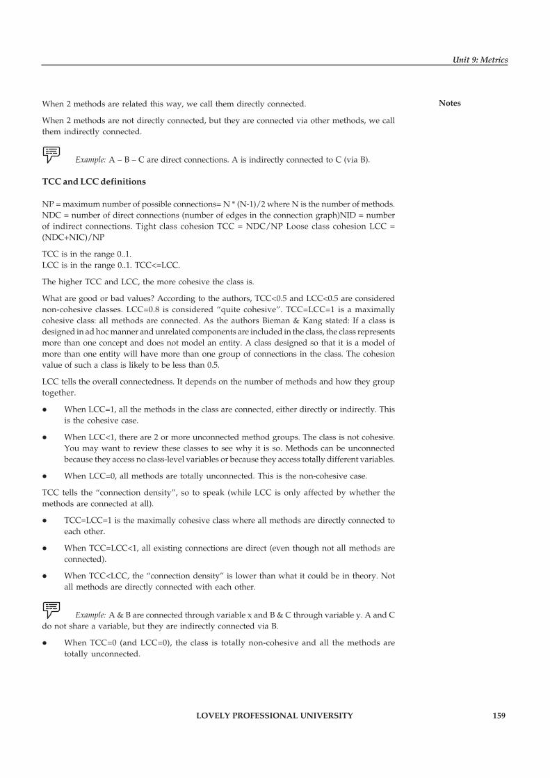
LOVELY PROFESSIONAL UNIVERSITY 159
Unit 9: Metrics
NotesWhen 2 methods are related this way, we call them directly connected.
When 2 methods are not directly connected, but they are connected via other methods, we callthem indirectly connected.
Example: A – B – C are direct connections. A is indirectly connected to C (via B).
TCC and LCC definitions
NP = maximum number of possible connections= N * (N-1)/2 where N is the number of methods.NDC = number of direct connections (number of edges in the connection graph)NID = numberof indirect connections. Tight class cohesion TCC = NDC/NP Loose class cohesion LCC =(NDC+NIC)/NP
TCC is in the range 0..1.LCC is in the range 0..1. TCC<=LCC.
The higher TCC and LCC, the more cohesive the class is.
What are good or bad values? According to the authors, TCC<0.5 and LCC<0.5 are considerednon-cohesive classes. LCC=0.8 is considered “quite cohesive”. TCC=LCC=1 is a maximallycohesive class: all methods are connected. As the authors Bieman & Kang stated: If a class isdesigned in ad hoc manner and unrelated components are included in the class, the class representsmore than one concept and does not model an entity. A class designed so that it is a model ofmore than one entity will have more than one group of connections in the class. The cohesionvalue of such a class is likely to be less than 0.5.
LCC tells the overall connectedness. It depends on the number of methods and how they grouptogether.
� When LCC=1, all the methods in the class are connected, either directly or indirectly. Thisis the cohesive case.
� When LCC<1, there are 2 or more unconnected method groups. The class is not cohesive.You may want to review these classes to see why it is so. Methods can be unconnectedbecause they access no class-level variables or because they access totally different variables.
� When LCC=0, all methods are totally unconnected. This is the non-cohesive case.
TCC tells the “connection density”, so to speak (while LCC is only affected by whether themethods are connected at all).
� TCC=LCC=1 is the maximally cohesive class where all methods are directly connected toeach other.
� When TCC=LCC<1, all existing connections are direct (even though not all methods areconnected).
� When TCC<LCC, the “connection density” is lower than what it could be in theory. Notall methods are directly connected with each other.
Example: A & B are connected through variable x and B & C through variable y. A and Cdo not share a variable, but they are indirectly connected via B.
� When TCC=0 (and LCC=0), the class is totally non-cohesive and all the methods aretotally unconnected.
160 LOVELY PROFESSIONAL UNIVERSITY
Principles of Software Engineering
NotesExample: The example on the left shows the same class as above. The connections
considered are marked with thick violet lines.
A and B are connected via variable x. C and D are connected via variable y. E is not connectedbecause its call tree doesn’t access any variables. There are 2 direct (“tight”) connections. Thereare no additional indirect connections this time.
In the example on the right, we made C access x to increase cohesion.
Now {A, B, C} are directly connected via x. C and D are still connected via y and E staysunconnected. There are 4 direct connections, thus TCC=4/10.
The indirect connections are A–D and B–D. Thus, LCC=(4+2)/10=6/10.
9.3.4 Validity of Cohesion
Is data cohesion the right kind of cohesion? Should the data and the methods in a class berelated? If your answer is yes, these cohesion measures are the right choice for you. If, on theother hand, you don’t care about that, you don’t need these metrics.
There are several ways to design good classes with low cohesion.
Example: Here are some examples:
� A class groups related methods, not data. If you use classes as a way to group auxiliaryprocedures that don’t work on class-level data, the cohesion is low. This is a viable,cohesive way to code, but not cohesive in the “connected via data” sense.
� A class groups related methods operating on different data. The methods perform relatedfunctionalities, but the cohesion is low as they are not connected via data.
� A class provides stateless methods in addition to methods operating on data. The statelessmethods are not connected to the data methods and cohesion is low.
� A class provides no data storage. It is a stateless class with minimal cohesion. Such a classcould well be written as a standard module, but if you prefer classes instead of modules,the low cohesion is not a problem, but a choice.
� A class provides storage only. If you use a class as a place to store and retrieve related data,but the class doesn’t act on the data, its cohesion can be low. Consider a class thatencapsulates 3 variables and provides 3 properties to access each of these 3 variables. Sucha class displays low cohesion, even though it is well designed. The class could well be splitinto 3 small classes, yet this may not make any sense.
Figure 9.2: Example of TCC

LOVELY PROFESSIONAL UNIVERSITY 161
Unit 9: Metrics
Notes
Task Make distinction between cohesive class and non-cohesive class.
Self Assessment
Fill in the blanks:
11. …………………… metrics measure how well the methods of a class are related to eachother.
12. A …………………… class performs one function.
13. A …………………… class performs two or more unrelated functions.
14. …………………… measures the number of “connected components” in a class.
15. TCC=LCC=1 is the maximally cohesive class where all …………………… are directlyconnected to each other.
9.4 Summary
� Cyclomatic Complexity counts the number of decisions in the program, under theassumption that decisions are difficult for people.
� Cyclomatic complexity, also known as V(G) or the graph theoretic number, is probablythe most widely used complexity metric in software engineering.
� Cyclomatic complexity comes in a couple of variations as to what exactly counts as adecision.
� Boolean operators add internal complexity to the decisions, but they are not counted inCC. CC and CC3 are similar what comes to Booleans, but CC2 is different.
� Cyclomatic complexity equals the minimum number of test cases you must execute tocover every possible execution path through your procedure.
� Data Binding Metrics is a metric to capture the strength of coupling between modules in asoftware system.
� Cohesion metrics measure how well the methods of a class are related to each other. Acohesive class performs one function.
� Lack of cohesion means that a class performs more than one function.
9.5 Keywords
CC2: CC2 extends cyclomatic complexity by including Boolean operators in the decision count.
CC3: CC3 equals the regular CC metric, but each Select Case block is counted as one branch, notas multiple branches.
Cohesion Metrics: It measures how well the methods of a class are related to each other. Acohesive class performs one function.
Cyclomatic Complexity: Cyclomatic Complexity counts the number of decisions in the program,under the assumption that decisions are difficult for people.
162 LOVELY PROFESSIONAL UNIVERSITY
Principles of Software Engineering
Notes Data Binding Metrics: It is a metric to capture the strength of coupling between modules in asoftware system.
Indicator: An indicator is a metric or combination of metrics that provide insight into thesoftware process, a software project, or the product itself.
LCOM4: It measures the number of “connected components” in a class.
TCC: TCC equals the number of decisions + 1 in a project or a class.
9.6 Review Questions
1. Explain the concept of Cyclomatic complexity.
2. Discuss the decisions counted for each statement or construct.
3. Discuss the different variations of Cyclomatic complexity.
4. Illustrate the CC3 Cyclomatic complexity without Cases.
5. Describe the relationship between cyclomatic complexity and the “risk” in a procedure.
6. Explain the concept of total cyclomatic complexity.
7. What is Data Binding Metrics? Discuss.
8. Explain the different types of Data Binding Metrics.
9. Describe the different types of LCOM ‘lack of cohesion of methods’ metrics.
10. Compare and contrast Tight and Loose Class Cohesion.
Answers: Self Assessment
1. Cyclomatic Complexity 2. V(G) or the graph theoretic number
3. Boolean 4. CC2
5. CC3 6. Sum(CC)
7. Data Binding 8. Potential
9. Used 10. Actual
11. Cohesion 12. Cohesive
13. non-cohesive 14. LCOM4
15. methods
9.7 Further Readings
Books Rajib Mall, Fundamentals of Software Engineering, 2nd Edition, PHI.
Richard Fairpy, Software Engineering Concepts, Tata McGraw Hill, 1997.
R.S. Pressman, Software Engineering – A Practitioner’s Approach, 5th Edition, TataMcGraw Hill Higher education.
Sommerville, Software Engineering, 6th Edition, Pearson Education

LOVELY PROFESSIONAL UNIVERSITY 163
Unit 9: Metrics
Notes
Online links http://c2.com/cgi/wiki?CyclomaticComplexityMetric
http://www.guru99.com/cyclomatic-complexity.html
http://sunnyday.mit.edu/16.355/classnotes-metrics.pdf
http://beyondtesting.co.in/Magazine/index.php?option=com_content&view=article&id=88:basics-of-software-testing-metrics&catid=35:coverstory&Itemid=67
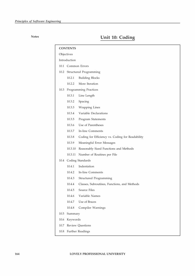
164 LOVELY PROFESSIONAL UNIVERSITY
Principles of Software Engineering
Notes Unit 10: Coding
CONTENTS
Objectives
Introduction
10.1 Common Errors
10.2 Structured Programming
10.2.1 Building Blocks
10.2.2 More Iteration
10.3 Programming Practices
10.3.1 Line Length
10.3.2 Spacing
10.3.3 Wrapping Lines
10.3.4 Variable Declarations
10.3.5 Program Statements
10.3.6 Use of Parentheses
10.3.7 In-line Comments
10.3.8 Coding for Efficiency vs. Coding for Readability
10.3.9 Meaningful Error Messages
10.3.10 Reasonably Sized Functions and Methods
10.3.11 Number of Routines per File
10.4 Coding Standards
10.4.1 Indentation
10.4.2 In-line Comments
10.4.3 Structured Programming
10.4.4 Classes, Subroutines, Functions, and Methods
10.4.5 Source Files
10.4.6 Variable Names
10.4.7 Use of Braces
10.4.8 Compiler Warnings
10.5 Summary
10.6 Keywords
10.7 Review Questions
10.8 Further Readings
LOVELY PROFESSIONAL UNIVERSITY 165
Unit 10: Coding
NotesObjectives
After studying this unit, you will be able to:
� Discuss common coding errors
� Explain the concept of structured programming
� Discuss programming practices
� Discuss coding standards used by developer
Introduction
When designing, and implementing software or applications, certain guidelines must be followedto ensure that your software meets the required qualities in order to function as intended. Theseguidelines also ensure that the final product is acceptable to your clients. Coding is what makesit possible for us to create computer software, apps and websites. The coding phase is the longestphase in the software development life cycle. Coding usually begins after the documentation ofthe design is finalized. This phase will almost entirely involve the work of the developer. Thecoding phase of the software life-cycle is concerned with the development of code that willimplement the design. This code is written is a formal language called a programming language.Programming languages have evolved over time from sequences of ones and zeros directlyinterpretable by a computer, through symbolic machine code, assembly languages, and finallyto higher-level languages that are more understandable to humans.
10.1 Common Errors
One common definition of a software error is a mismatch between the program and itsspecification. In other words, we can say, a software error is present in a program when theprogram does not do what its end user expects. Errors can cause a wide variety of differentproblems depending on the kind of program and the particular kind of bug involved.
Example: Some errors may cause programs to freeze and stop working.
Others have the potential to cause errors in the performance of the program that result in theprogram behaving in unexpected ways. Sometimes a software error can even cause a programto shut down completely.
Following are the most common software errors. This helps you to identify errors systematicallyand increases the efficiency and productivity of software testing.
Example: We have discussed below different types of errors with examples:
� User Interface Errors: Missing/Wrong Functions, Doesn’t do what the user expects, Missinginformation, Misleading, Confusing information, Wrong content in Help text,Inappropriate error messages. Performance issues - Poor responsiveness, Can’t redirectoutput, inappropriate use of key board.
� Error Handling: Inadequate – protection against corrupted data, tests of user input, versioncontrol; Ignores – overflow, data comparison, Error recovery – aborting errors, recoveryfrom hardware problems.
� Boundary Related Errors: Boundaries in loop, space, time, memory, mishandling of casesoutside boundary.
166 LOVELY PROFESSIONAL UNIVERSITY
Principles of Software Engineering
Notes � Calculation Errors: Bad Logic, Bad Arithmetic, Outdated constants, Calculation errors,Incorrect conversion from one data representation to another, Wrong formula, Incorrectapproximation.
� Initial and Later States: Failure to – set data item to zero, to initialize a loop-controlvariable, or re-initialize a pointer, to clear a string or flag, Incorrect initialization.
� Control Flow Errors: Wrong returning state assumed, Exception handling based exits,Stack underflow/overflow, Failure to block or unblock interrupts, Comparison sometimesyields wrong result, Missing/wrong default, Data Type errors.
� Errors in Handling or Interpreting Data: Unterminated null strings, Overwriting a fileafter an error exit or user abort.
� Race Conditions: Assumption that one event or task finished before another begins,Resource races, Tasks starts before its prerequisites are met, Messages cross or don’t arrivein the order sent.
� Load Conditions: Required resources are not available, No available large memory area,Low priority tasks not put off, Doesn’t erase old files from mass storage, Doesn’t returnunused memory.
� Hardware: Wrong Device, Device unavailable, Underutilizing device intelligence,Misunderstood status or return code, Wrong operation or instruction codes.
� Source, Version and ID Control: No Title or version ID, Failure to update multiple copiesof data or program files.
� Testing Errors: Failure to notice/report a problem, Failure to use the most promising testcase, Corrupted data files, Misinterpreted specifications or documentation, Failure tomake it clear how to reproduce the problem, Failure to check for unresolved problemsjust before release, Failure to verify fixes, Failure to provide summary report.
Self Assessment
State whether the following statements are true or false:
1. A software error is a mismatch between the program and its specification.
2. Sometimes a software error can cause a program to shut down completely.
10.2 Structured Programming
Structured Programming is a method of planning programs that avoids the branching categoryof control structures. Structured programming is a technique for organizing and coding computerprograms in which a hierarchy of modules is used, each having a single entry and a single exitpoint, and in which control is passed downward through the structure without unconditionalbranches to higher levels of the structure. Three types of control flow are used: sequential, testor selection, and iteration. Software engineering is a discipline that is concerned with theconstruction of robust and reliable computer programs. Just as civil engineers will use tried andtested methods for the construction of buildings, software engineers will use accepted methodsfor analysing a problem to be solved, a blueprint or plan for the design of the solution and aconstruction method that minimises the risk of error. The discipline has evolved as the use ofcomputers has spread. In particular, it has tackled issues that have arisen as a result of somecatastrophic failures of software projects involving teams of programmers writing thousands oflines of program code. Just as civil engineers have learned from their failures so have softwareengineers.
LOVELY PROFESSIONAL UNIVERSITY 167
Unit 10: Coding
NotesThe single most important idea of structured programming is that the code you write shouldrepresent a clear, simple and straightforward solution to the problem at hand.
One of the basic precepts of structured programming has been with us clear through our softwareengineering sojourn: a structured program consists of a hierarchical collection of individualmodules, which appear more abstract at the top levels and more detailed at the lower levels.This fits with our overall strategy of hierarchical decomposition, which we’ve followed fromstructured system specification through structured design and now down to structuredprogramming. The process of building a program in this fashion is called “top-downprogramming,” or step-wise refinement.
Each of these modules (or processes, in design terms) communicates with others through well-defined data interfaces. These data interfaces typically are subroutine parameter lists or functionargument lists. Each part of the program appears to other parts as a black box that simplyperforms its assigned function in some unknown way.
You’ve encountered this idea every time you called a built-in function in some programminglanguage. Think about 8-bit Atari BASIC. Do you recall the STICK function? It told you somethingabout the position of the joystick. Do you know how to communicate with the STICK function?Yes; all you had to do was pass it the number of the joystick you were interested in, like this:STICK(1), and it returned a numeric answer. Do you know how it worked? No; could be magic,for all you know. Do you care? No. This is the beauty of a “black box” approach to softwaredevelopment. There’s no reason why the modules you write should be any different in thisregard than the modules supplied by the guys who wrote the language you’re using.
In practice, you apply the notion of step-wise refinement by writing your initial description ofeach fundamental process in a very high-level “language” that we called pseudocode. This is afirst attempt at a picture of how each process will accomplish its assigned task. As you continuedown the path from design toward code, you add detail to this description until eventually youreach something that conforms to the exact syntax of the language you’re using: source code.
We suppose we could consider that one additional step takes place even after this, which is thecompiling of your source code into something the computer can deal with: object code.Fortunately, we humans can halt our step-wise refinement at the source code stage and let themachine take over from there.
The first thing most people learn about structured programming is that you shouldn’t use GOTOstatements. We don’t always have a choice.
Did u know? In older forms of BASIC, GOTO statements were needed everywhere, becausethere just wasn’t the richness of commands that we need to avoid GOTO.
!Caution The careless use of GOTO inevitably leads to the notorious “spaghetti code” thatmakes a program nearly impossible to comprehend and debug.
The worst case is a GOTO that branches back to a previous statement in the program listing.
Modern programming languages provide logic and control commands that allow us to almostcompletely avoid using GOTO statements (we’ll discuss these shortly). However, there are stilla few situations in which a GOTO actually can result in cleaner, more understandable code.Error-handling situations sometimes benefit from GOTOs. Premature exits from loops, orbreaking out of deeply nested IF structures, may be more easily handled with a GOTO than bysome other method. Nonetheless, the general guideline that GOTOs should not be used for
168 LOVELY PROFESSIONAL UNIVERSITY
Principles of Software Engineering
Notes routine transfer of control within a program is still valid, so try to break any lingering badhabits from your earlier experiences with BASIC interpreters.
The programming style you use can greatly influence the readability of your code. While notstrictly part of structured programming, there are some matters of style to keep in mind. Thefollowing represent some of the highlights of programming style; some don’t apply to allprogramming languages.
Use indentation to visually block logically related sections of your code, such as the sections ofIF/ELSE IF/ELSE/END IF and SELECT/CASE constructs. Use blank lines in the source code tofurther delineate sections of the program. Use comments judiciously in the source code forclarification (we talked about this last time), and make sure the comments are accurate. Don’tbother to document bad code—rewrite it, instead. Never put more than one statement on thesame source line. We always did this in Atari BASIC because it saved six bytes per statement, butyou don’t need such tricks when you have a megabyte at your disposal.
Select meaningful variable and procedure names. Don’t use different names to represent thesame piece of information (refer to your data dictionary). Explicitly declare the type of eachvariable used, if your language permits this. Use parentheses to resolve any ambiguities inmathematical expressions, even if they aren’t required for the operation to be executed correctly.Make sure conditional tests (IF some condition THEN do something) read clearly. Generallyspeaking, the first condition tested for should be the desired condition, with an error conditionhandled second.
Program defensively: Try to anticipate all possible errors in input data or mathematicaloperations, and write code to handle such situations. This includes validating input data beforetrying to use it and testing for such mathematical problems as division by 0 or taking thelogarithm of a negative number. Make sure that input data does not exceed the bounds of whatthe routine can handle. Think of the user when designing your programs; make input easy toprepare correctly, and make output self-explanatory.
Initialize variables before using them. Who knows what was in those bytes before they werereserved for a variable’s use? Avoid multiple entry points, and exits from loops and subroutines.
The first priority is to get the program running correctly. You can worry about optimizationlater. And when you do, make sure the program still runs correctly. Don’t try to optimize everylittle step; the compiler will do a lot of this for you. Usually, a program spends most of its timein a small section of the code, so concentrate your optimization efforts here (if you can find it).
Use the best algorithms you can find for calculations, but remember that both the algorithm andthe structure of your data will influence how the algorithm will be implemented in code. Insert“instrumentation” checkpoints in your programs to write out intermediate results someplace;so that you can verify accuracy, track down errors and assess efficiency. These outputs can besent to a trace file on the disk, which you can then examine at your leisure.
10.2.1 Building Blocks
Another basic premise of structured programming states that any program logic, no matter howcomplex, can be expressed in terms of just three kinds of logical operations: sequence, selectionand iteration. A program then is made up of a series of blocks of code to perform these operations.Let’s define these three kinds of operations.
Sequence—a series of program statements are executed one after the other, in the order in whichthey appear in the source code. Obviously, this rules out statements like GOTO and IF, restrictingus just to statements that perform some specific action. (A CALL or GOSUB to another procedurewould qualify as an action in this sense.) Hence, a block of statements that are executedsequentially is called an “action block.”

LOVELY PROFESSIONAL UNIVERSITY 169
Unit 10: Coding
NotesSelection—one set of statements, from a choice of two or more, is selected for sequential execution,based on some criterion. One way to accomplish this is to use an IF/THEN/ELSE construct.Some of the languages will also permit a SELECT/CASE/OTHERWISE/END - type structure,perhaps with different but analogous keywords. The set of statements that gets executed in eachcase is itself an action block. Sometimes selection constructs are called “branch blocks.”
Iteration—a series of statements is executed repeatedly until some termination condition is met.These are also called “loop blocks.” Virtually all languages contain simple FOR/NEXT or DO/END-type loops. More modern languages include variations such as DO UNTIL/END and DOWHILE/END.
These three kinds of “control blocks” have some features in common. First, the code in each isexecuted from top to bottom, which is the same way that it appears in the source file. This makesthe program much easier to read and understand than does the convoluted branching you findin so many BASIC programs. Of course, in a selection block, not every statement is executed, andin a loop block they may be executed more than once, but they still are always executed from topto bottom.
In addition, each control block has just one logical entry point: the first statement. And if they’rewell structured, they have just one logical exit point: the last statement. A complete program iswritten by assembling and nesting blocks of these three kinds to perform the required processing.
Believe it or not, it’s possible to write more or less structured programs in BASIC by followingthese rules. Some simulation of certain missing language features is required and some GOTOsinevitably creep in. But by keeping the notion of just three flavors of control blocks in mind, asurprisingly good job of structured programming can be done.
Task Compare and contrast loop blocks and control blocks.
10.2.2 More Iteration
Let us imagine we are pretty comfortable with the ideas behind action blocks and selectionblocks, but let’s take a close look at the iteration, or repetition, constructs. The simplest type ofloop looks like this in BASIC:
FOR I = 1 TO 10calculate something
NEXT I
In other languages, such a loop is commonly called a DO loop and is terminated by an END orEND DO statement:
DO I = 1 TO 10calculate something
END
In either case, some test is used to determine the number of times the loop is executed. In thesesimple examples, a variable called I (the index variable) is incremented after each iteration andcompared to the value 10. If I is less than or equal to 10, the statements in the loop are executedagain; otherwise, execution of the loop terminates. Here we’re assuming that the value of I willgo up by one on each iteration. Of course, you can set a different step interval with a statementlike: DO I = 1 TO 10 BY 0.5.
Here’s the key question: Is the comparison done before the loop is executed or after? There’s abig difference. Suppose I has a value of 20 at the time this loop is encountered in the course of

170 LOVELY PROFESSIONAL UNIVERSITY
Principles of Software Engineering
Notes executing the program. Will the loop be executed (since the value of the index variable isalready greater than 10) or not?
In Atari BASIC, the comparison is done after the contents of the loop are executed, so the loop isalways executed at least once. This is generally true of simple FOR/NEXT and DO/END loops.Many modern languages resolve any ambiguity by providing two explicit statement choices:DO WHILE and DO UNTIL. In a DO UNTIL loop, the termination condition is tested at the endof the loop, so the loop is always executed at least once. The simple FOR/NEXT loop in BASICis thus a DO UNTIL type loop. In a DO WHILE construct, the termination condition is tested atthe beginning of the loop. If the termination condition is already true, the contents of the looparen’t executed at all.
One important point is that DO WHILE and DO UNTIL loops need not rely on a changing indexvariable in the termination test. Any logical expression can be used, such as: DO UNTIL STATUS= ‘DONE’. It also may be possible to have complex combinations of termination conditions,either of which could cause loop execution to cease.
Example: Consider this example, which will terminate either when I is greater than 100or when J becomes less than or equal to 30:
D0 I = 1 To 100 BY 10 WHILE J > 30calculate something
END
Maybe it will help to see a visual representation of these two looping structures. In flowcharts,the action statements are represented with rectangles and decisions with diamonds. Figure l0.1uses a fragment of a flowchart to illustrate that, in a DO WHILE loop, the conditional test is donebefore the action statements are executed. In Figure 10.2, you see that the conditional test for aDO UNTIL is performed after the action statements are executed.
Source: http://www.atarimagazines.com/st-log/issue35/42_1_SOFTWARE_ENGINEERING.php
Figure 10.1: Conditional Test is done before the Action Statements are Executed

LOVELY PROFESSIONAL UNIVERSITY 171
Unit 10: Coding
Notes
Source: http://www.atarimagazines.com/st-log/issue35/42_1_SOFTWARE_ENGINEERING.php
Source: http://www.atarimagazines.com/st-log/issue35/42_1_SOFTWARE_ENGINEERING.php
There are times when you want execution of a loop to end prematurely, for a variety of reasons.Bad input data may have been encountered, some error condition may have cropped up orwhatever. Remember that we want to write our code so that each control block has only onelogical exit point, so let’s resist the impulse to GOTO out of the loop. A DO WHILE is a goodapproach, because you can put the anticipated error or exit conditions into the WHILE clause:
DO I = 1 TO 10 WHILE EOF = ‘FALSE’ AND INPUT = ‘OK’
Figure 10.2: Conditional Test for a DO UNTIL
Figure 10.3: DO WHILE and DO UNTIL

172 LOVELY PROFESSIONAL UNIVERSITY
Principles of Software Engineering
Notes But things can get tricky if you don’t have a DO WHILE available; you may just have to violatethe one-exit rule. Some languages provide a command like LEAVE for premature loop exits. InBASIC, you can set the index variable to its termination condition, so that the loop isn’t executedanymore; FORTRAN won’t let you do this. A more graceful solution is to use an IF block thattests for the abnormal termination condition right inside your DO block:
DO I = 1 TO 10IF EOF = ‘FALSE’ AND INPUT = ‘OK’ THEN
DOcalculate something
ENDEND IF
END
This is basically a way to simulate the DO WHILE command with your own explicit test.
Notes The innermost DO/END block without any loop criteria on the DO statement. Thisis really defining an action block to be executed within the selection block (IF/END IF),not a loop block. If you prefer, you can think of this as a loop block that gets executedexactly one time.
The structured programming concepts are all geared toward making the programs you writemore understandable to human beings. The computer doesn’t care if your program makessense, so long as it compiles properly. But anyone who must understand how your programworks needs all the help he or she can get. You can provide that help not only by using goodstructured programming practices, but also by using common sense. Keeping your code clearand simple, rather than cute, condensed or clever, will go a long way toward writing programsthat are easy to read, comprehend and alter.
Task Make distinction between DO WHILE and DO UNTIL.
Self Assessment
Fill in the blanks:
3. …………………… is a method of planning programs that avoids the branching categoryof control structures.
4. …………………… is a discipline that is concerned with the construction of robust andreliable computer programs.
5. Modern programming languages provide logic and control commands that allow us toalmost completely avoid using …………………… statements.
6. …………………… is a series of program statements are executed one after the other, in theorder in which they appear in the source code.
7. In case of ……………………, a series of statements is executed repeatedly until sometermination condition is met.
8. Each …………………… block has just one logical entry point: the first statement.

LOVELY PROFESSIONAL UNIVERSITY 173
Unit 10: Coding
Notes10.3 Programming Practices
General coding guidelines provide the programmer with a set of best practices which can beused to make programs easier to read and maintain. Unlike the coding standards, the use ofthese guidelines is not mandatory. However, the programmer is encouraged to review themand attempt to incorporate them into his/her programming style where appropriate. Most ofthe examples use the C language syntax but the guidelines can be applied to all languages.
10.3.1 Line Length
It is considered good practice to keep the lengths of source code lines at or below 80 characters.Lines longer than this may not be displayed properly on some terminals and tools. Someprinters will truncate lines longer than 80 columns. FORTRAN is an exception to this standard.Its line lengths cannot exceed 72 columns.
10.3.2 Spacing
The proper use of spaces within a line of code can enhance readability. Good rules of thumb areas follows:
A keyword followed by a parenthesis should be separated by a space.
� A blank space should appear after each comma in an argument list.
� All binary operators except “.” should be separated from their operands by spaces.
� Blank spaces should never separate unary operators such as unary minus, increment (“++”),and decrement(“—”) from their operands.
� Casts should be made followed by a blank space.
Example: Bad:
cost=price+(price*sales_tax);fprintf(stdout,”The total cost is %5.2f\n”,cost);
Better:cost = price + (price * sales_tax);fprintf (stdout, “The total cost is %5.2f\n”, cost);
10.3.3 Wrapping Lines
When an expression will not fit on a single line, break it according to these following principles:
� Break after a Comma
Example: fprintf (stdout, “\nThere are %d reasons to use standards\n”, num_reasons);
� Break after an Operator
Example: long int total_apples = num_my_apples + num_his_apples +num_her_apples;

174 LOVELY PROFESSIONAL UNIVERSITY
Principles of Software Engineering
Notes � Prefer Higher-level Breaks to Lower-level Breaks
Example: Bad:
longName1 = longName2 * (longName3 + LongName4 – longName5) + 4 * longName6;
Better:longName1 = longName2 * (longName3 + LongName4 – LongName5) + 4 * longName6;
� Align the new line with the beginning of the expression at the same level on the previousline.
Example: total_windows = number_attic_windows + number_second_floor_windows+ number_first_floor_windows;
10.3.4 Variable Declarations
Variable declarations that span multiple lines should always be preceded by a type.
Example: Acceptable:
int price, score;Acceptable:int price;int score;
Not Acceptable:int price,score;
10.3.5 Program Statements
Program statements should be limited to one per line. Also, nested statements should be avoidedwhen possible.
Example: Bad:
number_of_names = names.length; b = new JButton [ number_of_names ];
Better:number_of_names = names.length;b = new JButton [ number_of_names ];
10.3.6 Use of Parentheses
It is better to use parentheses liberally. Even in cases where operator precedence unambiguouslydictates the order of evaluation of an expression, often it is beneficial from a readability point ofview to include parentheses anyway.
Example: Acceptable:
total = 3 – 4 * 3;
Better:total = 3 – (4 * 3);
LOVELY PROFESSIONAL UNIVERSITY 175
Unit 10: Coding
NotesEven better:total = (-4 * 3) + 3;
10.3.7 In-line Comments
In-line comments promote program readability. They allow a person not familiar with the codeto more quickly understand it. It also helps the programmer who wrote the code to rememberdetails forgotten over time. This reduces the amount of time required to perform softwaremaintenance tasks.
As the name suggests, in-line comments appear in the body of the source code itself. Theyexplain the logic or parts of the algorithm which are not readily apparent from the code itself.In-line comments can also be used to describe the task being performed by a block of code.
In-line comments should be used to make the code clearer to a programmer trying to read andunderstand it. Writing a well structured program lends much to its readability even without in-line comments. The bottom line is to use in-line comments where they are needed to explaincomplicated program behavior or requirements. Use in-line comments to generalize what ablock of code, conditional structure, or control structure is doing. Do not use overuse in-linecomments to explain program details which are readily obvious to an intermediately skilledprogrammer.
Did u know? A rule of thumb is that in-line comments should make up 20% of the totallines of code in a program, excluding the header documentation blocks.
10.3.8 Coding for Efficiency vs. Coding for Readability
There are many aspects to programming. These include writing software that runs efficientlyand writing software that is easy to maintain. These two goals often collide with each other.Creating code that runs as efficiently as possible often means writing code that uses tricky logicand complex algorithms, code that can be hard to follow and maintain even with ample in-linecomments.
!Caution The programmer needs to carefully weigh efficiency gains versus programcomplexity and readability.
If a more complicated algorithm offers only small gains in the speed of a program, theprogrammer should consider using a simpler algorithm. Although slower, the simpler algorithmwill be easier for other programmers to understand.
Task Illustrate the different aspects of programming.
10.3.9 Meaningful Error Messages
Error handling is an important aspect of computer programming. This not only includes addingthe necessary logic to test for and handle errors but also involves making error messagesmeaningful.
Error messages should be meaningful. When possible, they should indicate what the problemis, where the problem occurred, and when the problem occurred. A useful Java exception handling
176 LOVELY PROFESSIONAL UNIVERSITY
Principles of Software Engineering
Notes feature is the option to show a stack trace, which shows the sequence of method calls which ledup to the exception.
Code which attempts to acquire system resources such as dynamic memory or files shouldalways be tested for failure.
Error messages should be stored in way that makes them easy to review. For non interactiveapplications, such as a program which runs as part of a cron job, error messages should belogged into a log file. Interactive applications can either send error messages to a log file,standard output, or standard error. Interactive applications can also use popup windows todisplay error messages.
10.3.10 Reasonably Sized Functions and Methods
Software modules and methods should not contain an excessively large number of lines of code.They should be written to perform one specific task. If they become too long, then chances arethe task being performed can be broken down into sub-tasks which can be handled by newroutines or methods.
A reasonable number of lines of code for routine or a method is 200. This does not includedocumentation, either in the function/method header or in-line comments.
10.3.11 Number of Routines per File
It is much easier to sort through code you did not write and you have never seen before if thereare a minimal number of routines per file. This is only applicable to procedural languages suchas C and FORTRAN. It does not apply to C++ and Java where there tends to be one public classdefinition per file.
Self Assessment
State whether the following statements are true or false:
9. Variable declarations that span multiple lines should always be preceded by a type.
10. Program statements should be limited to two per line.
11. In-line comments does not promote program readability.
12. In-line comments appear in the body of the source code itself.
13. Error messages should be stored in way that makes them easy to review.
10.4 Coding Standards
General coding standards pertain to how the developer writes code.
10.4.1 Indentation
Proper and consistent indentation is important in producing easy to read and maintainableprograms. Indentation should be used to:
� Emphasize the body of a control statement such as a loop or a select statement
� Emphasize the body of a conditional statement
� Emphasize a new scope block

LOVELY PROFESSIONAL UNIVERSITY 177
Unit 10: Coding
NotesA minimum of 3 spaces shall be used to indent. Generally, indenting by three or four spaces isconsidered to be adequate. Once the programmer chooses the number of spaces to indent by,then it is important that this indentation amount be consistently applied throughout the program.Tabs shall not be used for indentation purposes.
Example: The example given below shows the indentation used in a loop construct andin a conditional statement.
/* Indentation used in a loop construct. Four spaces are used for indentation. */for (int i = 0; i < number_of_employees; ++i){total_wages += employee [ i ] . wages;}//Indentation used in the body of a method.package void get_vehicle_info (){System.out.println (“VIN: “ + vin);System.out.println (“Make: “ + make);System.out.println (“Model: “ + model);System.out.println (“Year: “ + year);}/* Indentation used in a conditional statement. */IF (IOS .NE. 0)WRITE (*, 10) IOSENDIF10 FORMAT (“Error opening log file: “, I4)
10.4.2 In-line Comments
In-line comments explaining the functioning of the subroutine or key aspects of the algorithmshall be frequently used.
10.4.3 Structured Programming
Structured (or modular) programming techniques shall be used. GO TO statements shall not beused as they lead to “spaghetti” code, which is hard to read and maintain, except as outlined inthe FORTRAN Standards and Guidelines.
10.4.4 Classes, Subroutines, Functions, and Methods
Keep subroutines, functions, and methods reasonably sized. This depends upon the languagebeing used. A good rule of thumb for module length is to constrain each module to one functionor action (i.e. each module should only do one “thing”). If a module grows too large, it is usuallybecause the programmer is trying to accomplish too many actions at one time.
The names of the classes, subroutines, functions, and methods shall have verbs in them.
That is the names shall specify an action, e.g. “get_name”, “compute_temperature”.
10.4.5 Source Files
The name of the source file or script shall represent its function. All of the routines in a file shallhave a common purpose.

178 LOVELY PROFESSIONAL UNIVERSITY
Principles of Software Engineering
Notes 10.4.6 Variable Names
Variable shall have mnemonic or meaningful names that convey to a casual observer, the intentof its use. Variables shall be initialized prior to its first use.
10.4.7 Use of Braces
In some languages, braces are used to delimit the bodies of conditional statements, controlconstructs, and blocks of scope. Programmers shall use either of the following bracing styles:
for (int j = 0; j < max_iterations; ++j){/* Some work is done here. */}or the Kernighan and Ritchie style:for (int j = 0; j < max_iterations; ++j) {/* Some work is done here. */}
It is felt that the former brace style is more readable and leads to neater-looking code than thelatter style, but either use is acceptable.
Notes Whichever style is used, be sure to be consistent throughout the code. When editingcode written by another author, adopt the style of bracing used.
10.4.8 Compiler Warnings
Compilers often issue two types of messages: warnings and errors. Compiler warnings normallydo not stop the compilation process. However, compiler errors do stop the compilation process,forcing the developer to fix the problem and recompile. Compiler and linker warnings shall betreated as errors and fixed. Even though the program will continue to compile in the presence ofwarnings, they often indicate problems which may affect the behavior, reliability and portabilityof the code. Some compilers have options to suppress or enhance compile-time warning messages.Developers shall study the documentation and/or man pages associated with a compiler andchoose the options which fully enable the compiler’s code-checking features.
Example: The Wall option fully enables the gcc code checking features and should alwaysbe used:
gcc -Wall
Self Assessment
State whether the following statements are true or false:
14. The name of the source file or script shall represent its function.
15. Compiler errors stop the compilation process.
LOVELY PROFESSIONAL UNIVERSITY 179
Unit 10: Coding
Notes10.5 Summary
� A software error is present in a program when the program does not do what its end userexpects.
� Errors can cause a wide variety of different problems depending on the kind of programand the particular kind of bug involved.
� Structured Programming is a method of planning programs that avoids the branchingcategory of control structures.
� The single most important idea of structured programming is that the code you writeshould represent a clear, simple and straightforward solution to the problem at hand.
� General coding guidelines provide the programmer with a set of best practices which canbe used to make programs easier to read and maintain.
� In-line comments promote program readability. They allow a person not familiar withthe code to more quickly understand it.
� If a more complicated algorithm offers only small gains in the speed of a program, theprogrammer should consider using a simpler algorithm.
� Compiler warnings normally do not stop the compilation process. However, compilererrors do stop the compilation process, forcing the developer to fix the problem andrecompile.
10.6 Keywords
Compiler Errors: Compiler errors do stop the compilation process, forcing the developer to fixthe problem and recompile.
Compiler Warnings: Compiler warnings is a message which normally do not stop the compilationprocess.
Error Handling: Error handling includes adding the necessary logic to test for and handle errorsbut also involves making error messages meaningful.
In-line Comments: In-line comments allow a person not familiar with the code to more quicklyunderstand it.
Sequence: Sequence is a series of program statements are executed one after the other, in theorder in which they appear in the source code.
Series: A series of statements is executed repeatedly until some termination condition is met.
Software Error: A software error is a mismatch between the program and its specification.
Structured Programming: Structured Programming is a method of planning programs thatavoids the branching category of control structures.
10.7 Review Questions
1. Discuss different types of common errors with example.
2. Explain the technique used for organizing and coding computer programs.
3. Discuss the basic principles of structured programming.
180 LOVELY PROFESSIONAL UNIVERSITY
Principles of Software Engineering
Notes 4. Describe the building blocks of structured programming.
5. What are the different types of control blocks? Discuss.
6. Discuss the best programming practices which can be used to make programs easier toread and maintain.
7. Illustrate how the use of spaces within a line of code can enhance readability.
8. Illustrate the use of Parentheses with example.
9. What are in-line comments? Discuss the use of in-line comments.
10. Discuss the general coding standards used by the developer when writing code.
Answers: Self Assessment
1. True 2. True
3. Structured Programming 4. Software engineering
5. GOTO 6. Sequence
7. Iteration 8. Control
9. True 10. False
11. False 12. True
13. True 14. True
15. False
10.8 Further Readings
Books Rajib Mall, Fundamentals of Software Engineering, 2nd Edition, PHI.
Richard Fairpy, Software Engineering Concepts, Tata McGraw Hill, 1997.
R.S. Pressman, Software Engineering – A Practitioner’s Approach, 5th Edition, TataMcGraw Hill Higher education.
Sommerville, Software Engineering, 6th Edition, Pearson Education
Online links http://software-engineering142.blogspot.in/2009/04/coding-phase.html
http://www.computer.org/portal/web/certification/resources/code_of_ethics
http://www.indeed.com/q-Software-Process-Engineer-Coding-Standard-Practice-jobs.html
http://www.win.tue.nl/~wstomv/edu/jpid/Coding_Standard_Motivation-4up.pdf
LOVELY PROFESSIONAL UNIVERSITY 181
Unit 11: Coding Process
NotesUnit 11: Coding Process
CONTENTS
Objectives
Introduction
11.1 Incremental Coding Process
11.2 Test Driven Programming
11.3 Pair Programming
11.3.1 Pair Programming, Rights and Responsibilities
11.3.2 Partnership Documentation
11.4 Summary
11.5 Keywords
11.6 Review Questions
11.7 Further Readings
Objectives
After studying this unit, you will be able to:
� Understand the Incremental Coding Process
� Discuss the Test driven Programming
� Explain the concept of Pair programming
Introduction
The coding activity starts when some form of design has been done and the specifications of themodules to be developed are available. The programming team must have a designated leader,a well-defined organization structure and a thorough understanding of the duties andresponsibilities of each team member. The implementation team must be provided with a well-defined set of software requirements, an architectural design specification, and a detailed designdescription. Also, each team member must understand the objectives of implementation. Afamous experiment by Weinberg showed that if programmers are specified a clear objective forthe program, they usually satisfy it.
11.1 Incremental Coding Process
Many novice programmers start a program with a “big bang” approach, meaning they want towrite the whole program in one step and then only they would try to compile and run. Howeveras humans we make many mistakes when programming, especially given that we have to use aprogramming language to do the job and most programming languages differ drastically fromnatural languages. Because it is very likely that we would make mistakes, we have to ensure thatwe leave room so that we could easily identify the mistakes we have made.
The solution to this situation is to adopt an incremental approach in programming. The idea isto keep building your code using several small working pieces. The pieces of code would not doa complete job. Rather they will lay out the skeleton for the final complete program.
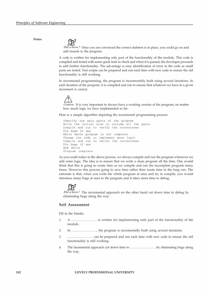
182 LOVELY PROFESSIONAL UNIVERSITY
Principles of Software Engineering
Notes
Did u know? Once you are convinced the correct skeleton is in place, you could go on andadd muscle to the program.
A code is written for implementing only part of the functionality of the module. This code iscompiled and tested with some quick tests to check and when it is passed, the developer proceedsto add further functionality. The advantage is easy identification of error in the code as smallparts are tested. Test scripts can be prepared and run each time with new code to ensure the oldfunctionality is still working.
In incremental programming, the program is incrementally built using several iterations. Ineach iteration of the program, it is compiled and run to ensure that whatever we have in a givenincrement is correct.
!Caution It is very important to always have a working version of the program, no matterhow much logic we have implemented so far.
Here is a simple algorithm depicting the incremental programming process:
Identify the main parts of the programWrite the initial stub to include all the partsCompile and run to verify the correctnessFix bugs if anyWhile whole program is not completeChange the code to implement more logicCompile and run to verify the correctnessFix bugs if anyEnd whileProgram complete
As you could notice in the above process, we always compile and run the program whenever weadd some logic. The idea is to ensure that we write a clean program all the time. One wouldthink that this is going to waste time as we compile and run the incomplete program manytimes. However this process going to save time rather than waste time in the long run. Therationale is that, when you write the whole program at once and try to compile, you wouldintroduce many bugs at once to the program and it takes more time to debug.
Did u know? The incremental approach on the other hand cut down time to debug byeliminating bugs along the way.
Self Assessment
Fill in the blanks:
1. A …………………… is written for implementing only part of the functionality of themodule.
2. In ……………………, the program is incrementally built using several iterations.
3. …………………… can be prepared and run each time with new code to ensure the oldfunctionality is still working.
4. The incremental approach cut down time to …………………… by eliminating bugs alongthe way.

LOVELY PROFESSIONAL UNIVERSITY 183
Unit 11: Coding Process
Notes11.2 Test Driven Programming
Test Driven Development (TDD) is a technique for building software that guides softwaredevelopment by writing tests. It was developed by Kent Beck in the late 1990s as part of ExtremeProgramming. The programmer first writes the test scripts then writes the code to pass the tests.The whole process is done incrementally.
In essence you follow three simple steps repeatedly:
� Write a test for the next bit of functionality you want to add.
� Write the functional code until the test passes.
� Refactor both new and old code to make it well structured.
You continue cycling through these three steps, one test at a time, building up the functionalityof the system. Writing the test first, what XPE2 calls Test-First Programming, provides two mainbenefits. Most obviously it’s a way to get SelfTestingCode, since you can only write somefunctional code in response to making a test pass. The second benefit is that thinking about thetest first forces you to think about the interface to the code first. This focus on interface and howyou use a class helps you separate interface from implementation.
Notes The most common way that we hear to screw up TDD is neglecting the third step.
Refactoring the code to keep it clean is a key part of the process; otherwise you just end up witha messy aggregation of code fragments. (At least these will have tests, so it’s a less painful resultthan most failures of design.)
Self Assessment
State whether the following statements are true or false:
5. Test Driven Development (TDD) is a technique for building software that guides softwaredevelopment by writing tests.
6. Refactoring the code to keep it clean is a key part of the process.
11.3 Pair Programming
Pair programming is the Software Engineering term for when two people collaborate andinteract to create a software solution. Both partners must take equal responsibility for readingthe class notes, reading the assignment requirements, typing code, reviewing their partner’scode, planning the direction of the project, etc. For the purposes of our course, pair programmingrequires that all of your work is done with your partner at the same computer at the same time.One person should be typing, one person should be directing; each person is responsible for allparts of the project. It is not allowable to have one person work on the first half and the otherwork on the second. Again, both partners must be actively working together at the same timefor all aspects of the problem set.
Working in a Team can be more than twice as effective as working alone. You can feed off of eachother’s knowledge and excitement. You can help each other when things go wrong. You canlearn from each other and study twice as much material. Sometimes you can finish assignmentsin less than half the time a single person would take!

184 LOVELY PROFESSIONAL UNIVERSITY
Principles of Software Engineering
Notes We will refer to our partnerships as “Pair Programming”. Pair programming is a techniquewhere two programmers sit side by side helping each other to complete a project. By workingtogether, syntax errors are more easily avoided, and more importantly logic errors can often becaught before running the program.
In Pair Programming, one programmer is the driver and the other is the navigator. While thedriver is typing (i.e., coding) the navigator is making strategic plans and correcting tactical(logical) errors.
Each partner should actively communicate with the other, bouncing ideas off one another,searching for information in the notes or book to solve the current problem (together), reviewingeach other’s typing (in real time), etc. By being able to “multi-task”, each partner bringing theirown view and expertise, the partnership will enable both partners to learn more, and learn“better”.
When pair up, you will gain certain rights and be held to certain responsibilities.
Task Find out the pros and cons of pair programming.
11.3.1 Pair Programming, Rights and Responsibilities
� You are allowed to (and required to) talk over all aspects of the program with yourpartner.
� You can meet with other groups/individuals away from the computer if you need toreason about and discuss the program on a high level. While you are actuallyprogramming, you should work exclusively with your partner.
� You should learn from your partner and help your partner to learn... if you find yourselfin a one-sided partnership, you should choose a new partner for the next assignment.
� Written work or analysis (when specified by the assignment) is to be done separately!Thus if the assignment requires a written report, both partners should complete theirown.
� You must choose your partner at least 4 days before the assignment is due or you will berequired to work on your own until the next programming assignment. In other words,you are not allowed to join someone who has already completed (or mostly completed)the assignment without you.
� You and your partner must both be present when you are entering your solution into thecomputer. You are not allowed to divide the program into sections and each completeseparate work. This defeats the goals of pair programming.
� You must strive to contribute an equal amount to your group.
� Again, you are not allowed to let one partner do “half” the work and you the other “half”.You both must work together in all aspects of the design and coding of the program.
� You must take equal turns driving (typing at the computer) and navigating (from the chairnext to the computer). In fact, you should endeavor to switch every 15 minutes or less.
� You are both required to keep a copy of the solution.
� One of you should turn in all the files. The other should only turn in the i_worked_withfile and the partner evaluation file (and any written work that is required as an individual).
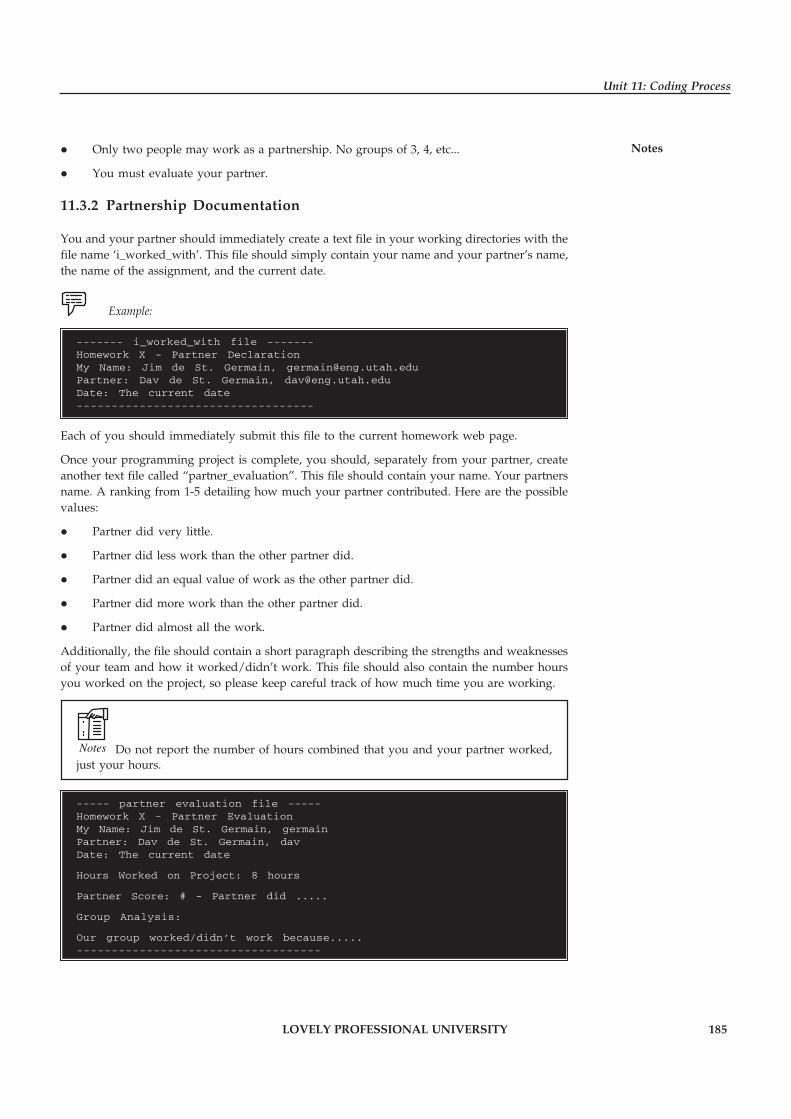
LOVELY PROFESSIONAL UNIVERSITY 185
Unit 11: Coding Process
Notes� Only two people may work as a partnership. No groups of 3, 4, etc...
� You must evaluate your partner.
11.3.2 Partnership Documentation
You and your partner should immediately create a text file in your working directories with thefile name ‘i_worked_with’. This file should simply contain your name and your partner’s name,the name of the assignment, and the current date.
Example:
------- i_worked_with file -------Homework X - Partner DeclarationMy Name: Jim de St. Germain, [email protected]: Dav de St. Germain, [email protected]: The current date----------------------------------
Each of you should immediately submit this file to the current homework web page.
Once your programming project is complete, you should, separately from your partner, createanother text file called “partner_evaluation”. This file should contain your name. Your partnersname. A ranking from 1-5 detailing how much your partner contributed. Here are the possiblevalues:
� Partner did very little.
� Partner did less work than the other partner did.
� Partner did an equal value of work as the other partner did.
� Partner did more work than the other partner did.
� Partner did almost all the work.
Additionally, the file should contain a short paragraph describing the strengths and weaknessesof your team and how it worked/didn’t work. This file should also contain the number hoursyou worked on the project, so please keep careful track of how much time you are working.
Notes Do not report the number of hours combined that you and your partner worked,just your hours.
----- partner evaluation file -----Homework X - Partner EvaluationMy Name: Jim de St. Germain, germainPartner: Dav de St. Germain, davDate: The current date
Hours Worked on Project: 8 hours
Partner Score: # - Partner did .....
Group Analysis:
Our group worked/didn’t work because.....-----------------------------------

186 LOVELY PROFESSIONAL UNIVERSITY
Principles of Software Engineering
Notes If you work with the same partner more than once, you should comment on how your partnershipis “maturing” or growing, and what went better the 2nd time around, etc. Alternatively, it is toyour advantage to work with several partners over the course of the semester to be able to learnfrom the strengths of other people. Don’t feel that you have to stay with the same partner everyweek.
Self Assessment
Fill in the blanks:
7. …………………… is the Software Engineering term for when two people collaborate andinteract to create a software solution.
8. Once your programming project is complete, you should, separately from your partner,create another text file called …………………….
9. In Pair Programming, one programmer is the …………………… and the other is the…………………….
10. Pair programming is a technique where …………………… sit side by side helping eachother to complete a project.
11.4 Summary
� In incremental programming, the program is incrementally built using several iterations.
� In each iteration of the program, it is compiled and run to ensure that whatever we havein a given increment is correct.
� We always compile and run the program whenever we add some logic.
� Test Driven Development (TDD) is a technique for building software that guides softwaredevelopment by writing tests.
� The most common way that we hear to screw up TDD is neglecting the third step.
� Pair programming is the Software Engineering term for when two people collaborate andinteract to create a software solution.
� Working in a Team can be more than twice as effective as working alone.
� In Pair Programming, one programmer is the driver and the other is the navigator.
� If you work with the same partner more than once, you should comment on how yourpartnership is “maturing” or growing, and what went better the 2nd time around, etc.
11.5 Keywords
Debugging: Debugging is a methodical process of finding and reducing the number of bugs, ordefects, in a computer program or a piece of electronic hardware, thus making it behaves asexpected.
Incrementing Programming: Incremental programming is a technique in which the program isincrementally built using several iterations.
Pair Programming: Pair programming is the Software Engineering term for when two peoplecollaborate and interact to create a software solution.
TDD: Test Driven Development (TDD) is a technique for building software that guides softwaredevelopment by writing tests.

LOVELY PROFESSIONAL UNIVERSITY 187
Unit 11: Coding Process
Notes11.6 Review Questions
1. What are the different processes of coding? Discuss.
2. Explain the concept of Incremental Coding Process.
3. “In incremental programming, the program is incrementally built using several iterations”.Comment.
4. Write a simple algorithm depicting the incremental programming process.
5. What is Test Driven Development (TDD)? Discuss.
6. Briefly explain the concept the pair programming.
7. Discuss about the pair programming, rights and responsibilities.
8. Explain the partnership documentation.
Answers: Self-Assessment
1. Code 2. Incremental programming
3. Test scripts 4. Debug
5. True 6. True
7. Pair programming 8. Partner_evaluation
9. Driver, navigator 10. Two programmers
11.7 Further Readings
Books Rajib Mall, Fundamentals of Software Engineering, 2nd Edition, PHI.
Richard Fairpy, Software Engineering Concepts, Tata McGraw Hill, 1997.
R.S. Pressman, Software Engineering – A Practitioner’s Approach, 5th Edition, TataMcGraw Hill Higher education.
Sommerville, Software Engineering, 6th Edition, Pearson Education
Online links c2.com/cgi/wiki?PairProgramming
www.extremeprogramming.org/rules/testfirst.html
www.klab.caltech.edu/~xhou/papers/nips08icl.pdf

188 LOVELY PROFESSIONAL UNIVERSITY
Principles of Software Engineering
Notes Unit 12: Refactoring
CONTENTS
Objectives
Introduction
12.1 Meaning of Refactoring
12.1.1 Benefits of Refactoring
12.1.2 Reasons to Refactor your Code
12.1.3 Leveraging Refactoring
12.1.4 Properties of Refactoring
12.1.5 Refactoring Examples
12.1.6 Pattern-based Refactoring
12.2 Verification
12.3 Software Metrics
12.3.1 Size of Metrics
12.4 Summary
12.5 Keywords
12.6 Review Questions
12.7 Further Readings
Objectives
After studying this unit, you will be able to:
� Know the meaning of Refactoring
� Discuss about Verification
� Explain the concept of Software Metrics
Introduction
Refactoring is a disciplined technique for restructuring an existing body of code, altering itsinternal structure without changing its external behavior. Its heart is a series of small behaviorpreserving transformations. Each transformation (called a ‘refactoring’) does little, but a sequenceof transformations can produce a significant restructuring. Since each refactoring is small, it’sless likely to go wrong. The system is also kept fully working after each small refactoring,reducing the chances that a system can get seriously broken during the restructuring. Coderefactoring is the process of changing a computer program’s source code without modifying itsexternal functional behavior, in order to improve some of the non-functional attributes of thesoftware.

LOVELY PROFESSIONAL UNIVERSITY 189
Unit 12: Refactoring
Notes12.1 Meaning of Refactoring
Refactoring is “the process of changing a software system in such a way that it does not alter theexternal behavior of the code yet improves its internal structure,” according to Martin Fowler,the “father” of refactoring.
Did u know? While refactoring can be applied to any programming language, the majorityof refactoring current tools has been developed for the Java language.
One approach to refactoring is to improve the structure of source code at one point and thenextend the same changes systematically to all applicable references throughout the program.The result is to make the code more efficient, scalable, maintainable or reusable, without actuallychanging any functions of the program itself. In his book, Fowler describes a methodology forcleaning up code while minimizing the chance of introducing new bugs.
In Refactoring:
� The system works fine, but its design and code can be improved.
� New local requirements and functions cannot be addressed or integrated appropriately.
According to Martin Fowler it is:
� Refactoring is the process of changing a software system in such a way that it does not alterthe external behavior of the code yet improves its internal structure.
� Refactoring is a disciplined way to clean up code that minimizes the chances of introducingbugs.
12.1.1 Benefits of Refactoring
Refactoring is usually motivated by noting a code’s smell (A code smell is a surface indicationthat usually corresponds to a deeper problem in the system.).
Example: The method at hand may be very long, or it may be a near duplicate of anothernearby method.
Once recognized, such problems can be addressed by refactoring the source code, or transformingit into a new form that behaves the same as before, but that no longer “smells”. For a longroutine, extract one or more smaller subroutines. Or, for duplicate routines, remove theduplication and utilize one shared function in their place. Failure to perform refactoring canresult in accumulating technical debt.
There are two general categories of benefits to the activity of refactoring:
� Maintainability: It is easier to fix bugs because the source code is easy to read and theintent of its author is easy to grasp. This might be achieved by reducing large monolithicroutines into a set of individually concise, well-named, single-purpose methods. It mightbe achieved by moving a method to a more appropriate class, or by removing misleadingcomments.
� Extensibility: It is easier to extend the capabilities of the application if it uses recognizabledesign patterns, and it provides some flexibility where none may have existed before.

190 LOVELY PROFESSIONAL UNIVERSITY
Principles of Software Engineering
Notes
Did u know? Refactoring is a huge aid in untangling production code without breaking it,and in improving its long-term maintainability.
Refactoring helps you achieve:
1. Self-documenting code, for better readability and maintainability, which is pretty muchthe only kind of code documentation that ever seems to stay current (Extract Method andIntroduce Local allow you to create function and variable names that are descriptiveenough to rarely need comments). Until you experience readable, self-describing code,you don’t know what you’re missing
2. Fine-grained encapsulation, for easier debugging and code reuse: Extract Methodautomatically determines the parameters needs in order to create a method from thecurrent selection, and handles them correctly. You then know exactly what externalinformation the selected block requires in order to operate. This can be a great aid inuntangling complex code during code reviews or debugging.
3. The generalization of existing code, to make it easier to apply existing code to a broaderrange of problems – as you Extract Method, you can easily replace things like hard-codedconstants (perhaps, a connection string, or a table name) with parameters, thus allowingthe application of proven code to new contexts.
12.1.2 Reasons to Refactor your Code
Whenever reading your code, if you stumble upon one of the following cases, it is probablybetter to stop and refactor that piece of code.
� Duplicate Code – There is no reason to have duplicate code. Try to respect the DRYprinciple (Don’t repeat yourself). As Parnas said best, “Copy and Paste is a design error”.Also, coding will become absolutely boring.
� A routine is too long – In OOP, you rarely need a routine longer than one screen. Considerbreaking it into multiple routines.
� A loop is too long or too deeply nested – Consider refactoring part of the code as routines,or changing the algorithm.
!Caution Nested loops are one of the biggest performance penalties.
� A class has poor cohesion – If a class has unrelated responsibilities, consider changing it.
� A parameter list has too many parameters – If you need to pass too many parameters,consider merging them in a cohesive class or rethinking the problem.
� Changes in a class tend to be compartmentalized – This may be a sign that the class shouldbe broken into smaller ones.
� Changes require parallel modifications in different classes – This is a sign that they aretied together. Try cut most of the dependencies. This kind of refactoring can be a realchallenge, but it is worthy.
� Inheritance hierarchies need parallel changes – This is a special kind for the problemabove.
� Case statements need parallel changes – Consider using inheritance with polymorphisminstead of case.

LOVELY PROFESSIONAL UNIVERSITY 191
Unit 12: Refactoring
Notes� Related data items that are used together are not tied into classes – The first time youcode/design, you may overlook some classes. Take your time and create them.
� A routine uses more features of another class than of its own – Probably it should bemoved into the other class
� A primitive data type is overloaded.
Example: You may use int to represent both money and temperature. It is better tocreate a Money and a Temperature class. By doing so, you will be able to impose customconditions on the types. Also the compiler will not allow you to mix money with temperatures.
� A class doesn’t do much – Maybe it should be merge with another.
� A chain of routines passes tramp data – If a routine takes some data only to pass it toanother, you should probably eliminate it.
� A middle man object does nothing – same as above.
� One class is very intimate to another – This works against one of your most powerfulcomplexity management tools: encapsulation.
� A routine has a poor name – In the best case, you can rename it. In the worst, the problemis the design. The name is just a sign. Anyway, take your time to solve this one.
� Data members are public – This is plain wrong. Today, you can use properties in manyprogramming languages, so hiding data behind them is very easy.
� A subclass uses a small percentage of the parent class – Usually, this denotes wronginheritance design.
� Comments are used to explain difficult code – Comments are very good, but creatingdifficult-to-understand code and commenting it is plain wrong.
� Global variables are used – There are few cases when global variables are the only logicaloption.
� You need setup/cleanup code before/after calling a routine – Try to merge this code intothe routine.
� A program contains code that might be needed someday – The only way to write codetaking into account future releases is to write it as clear and obvious as possible, enablingquick understanding and modification.
12.1.3 Leveraging Refactoring
It is essential to set up a huge test suite
� Refactoring steps are small (design a little, code a little, change a little, test)
� Worst problem or risk areas first
� If test suite fails start again
12.1.4 Properties of Refactoring
A Refactoring reveals the following parts:
� Name, for example: Extract Method
� Summary (of Situation), for example: Code fragment that can be grouped together.

192 LOVELY PROFESSIONAL UNIVERSITY
Principles of Software Engineering
Notes � Turn the fragment into a method whose name explains the purpose of the method
� Motivation.
Example: Use Extract Method when encountering long methods or replicated code
� Mechanics, for example:
� Create a new method and name it after the intention of the method
� Copy extracted code from source to new target method
� Scan extracted method for local variables
� If one mutated local variable, make method as a query that returns that local variable‘svalue. If more than one you might need to apply additional refactoring first (e.g.,Split Temporary Variable)
� Read-only local variables will be passed as parameters to new target method
� Compile
� Replace in source-code extracted code with call to new target method
� Compile and test
� Refactoring might be considered like patterns: forces, context, problem, solution
� Most refactoring are reversible
12.1.5 Refactoring Examples
We use three examples to explain some basic refactoring
� Extract Method:
� signalled by comments
� single-entry, single-exit
� increase the level of indirection
� reduce the length of a method
� increase the chance of reuse
� Move Method:
� Place method together with the object, Putting things together when changes aretogether
� Replace Conditions with Polymorphism:
� Switches are “hard code”, polymorphism is better for extensibility in OO
Example 1: Extract Method
void f() {
...
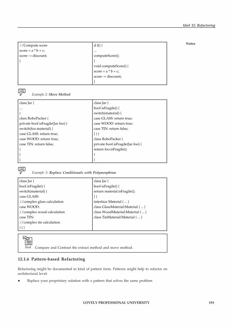
LOVELY PROFESSIONAL UNIVERSITY 193
Unit 12: Refactoring
Notes//Compute score score = a * b + c; score -= discount; }
d f() { ... computeScore(); } void computeScore() { score = a * b + c; score -= discount; }
Example 2: Move Method
class Jar { ... } class RoboPacker { private bool isFragile(Jar foo) { switch(foo.material) { case GLASS: return true; case WOOD: return true; case TIN: return false; } } }
class Jar { bool isFragile() { switch(material) { case GLASS: return true; case WOOD: return true; case TIN: return false; } } } class RoboPacker { private bool isFragile(Jar foo) { return foo.isFragile(); } }
Example 3: Replace Conditionals with Polymorphism
class Jar { bool isFragile() { switch(material) { case GLASS: //complex glass calculation case WOOD: //complex wood calculation case TIN: //complex tin calculation } } }
class Jar { bool isFragile() { return material.isFragile(); } } interface Material { ... } class GlassMaterial:Material { ... } class WoodMaterial:Material { ... } class TinMaterial:Material { ... }
Task Compare and Contrast the extract method and move method.
12.1.6 Pattern-based Refactoring
Refactoring might be documented in kind of pattern form. Patterns might help to refactor onarchitectural level:
� Replace your proprietary solution with a pattern that solves the same problem
194 LOVELY PROFESSIONAL UNIVERSITY
Principles of Software Engineering
Notes � Introduce symmetry and orthogonality by making sure the same problem is alwayssolved using the same pattern/solution
Self Assessment
Fill in the blanks:
1. …………………… is the process of changing a computer program’s source code withoutmodifying its external functional behavior.
2. …………………… is the process of changing a software system in such a way that it doesnot alter the external behavior of the code yet improves its internal structure.
3. A …………………… is a surface indication that usually corresponds to a deeper problemin the system.
4. …………………… loops are one of the biggest performance penalties.
5. …………………… need parallel changes – consider using inheritance with polymorphisminstead of case.
6. …………………… might help to refactor on architectural level.
12.2 Verification
Once we have decomposed a refactoring implementation both in terms of its functionality andin terms of the object language, we need to find a suitable verification method to prove correctnessof the components. If the correctness properties are simple enough, an intriguing possibilitywould be to use model checking techniques for automatic verification. Such an approach istaken by Estler et al., who verify refactorings on the Z specification language. The scope of theirapproach, however, seems to be very limited, and it is probably not applicable to generalpurpose refactoring tools. Inspiration can be drawn from the success of Rhodium, a domainspecific language for declaratively specifying dataflow analyses that are verified by an automatictheorem prover without any need for human intervention. However, analyses implemented inRhodium work on a simplified intermediate representation of programs, and it seems likelythat in order to verify source-level analyses interactive theorem proving is a more appropriatechoice. The experience of the CompCert project shows that verification of a compiler for asimple but realistic, C-like language is indeed possible with a theorem prover.
!Caution It is not clear that their techniques transfer to our setting, since many of thechallenges in refactoring are due to the complexities of dealing with a rich source language.
Sultana and Thompson have succeeded in mechanically verifying refactorings using the theoremprover Isabelle/HOL. Their success is heartening, but they are again only dealing with a verysimple object language and it is unclear how well their techniques would scale to larger languages,since they do not seem to put much emphasis on modularity.
The experiences of our own verification show that attribute grammars generally lend themselveswell to interactive proofs: the evaluation schemata of synthesised and inherited attributescorrespond (via Curry-Howard) to induction schemata, and in a prover with an extensible tacticlanguage like Coq the use of domain specific tactics simplifies commonly occurring proof stepsand provides some automation. Proofs involving circularly defined attributes are a bit moreproblematic, since explicit proofs of monotonicity have to be provided; additional automationwould be helpful here.

LOVELY PROFESSIONAL UNIVERSITY 195
Unit 12: Refactoring
NotesThe biggest challenge to verifying major refactorings, however, are extensible proofs. Since ourencoding of CRAGs maps attributes to Coq functions, which have to be defined en bloc, there isno way to match JastAdd’s mechanism for gradually extending attribute definitions to deal withnew language constructs. The same is true of proof scripts, which likewise are monolithicentities impervious to extensions. Although our experiments show that extending the languagerequires little additional code and only modest changes to the proof scripts, all these changesstill have to be performed in place and are hence not true extensions.
What we would like to see is a three-tiered extension mechanism, in which the object language,the refactoring implementations, and their proofs can all be extended modularly. In particular,the usual approach of introducing new language features in an extended language and thenprovide a semantics preserving translation back to a core calculus (as done, for example, forinner classes in) would not work here, since the analyses and transformations to be verifiedhave to work on the extended language, not on the core calculus.
We are thus facing the well-known expression problem:
Our underlying datatype is the abstract syntax of the object language, on which we write functions(the refactorings and their correctness proofs). Coq as a functional language is, for our purposes,located at the wrong end of the spectrum, where it is easy to extend the functions, but hard toextend the datatype. It would certainly be interesting to survey the literature of solutions to theexpression problem to see if they are applicable to our challenge.
Self Assessment
State whether the following statements are true or false:
7. Proofs involving circularly defined attributes are a bit more problematic.
8. The biggest challenge to verifying major refactoring are extensible proofs.
9. Data type is the abstract syntax of the object language, on which we write functions.
12.3 Software Metrics
We use software metrics to try to quantify particular characteristics of software systems, such asquality, maintainability, or reliability. In general, however, these characteristics cannot bemeasured directly. Instead, we directly measure particular attributes of software by using softwaremetrics and then infer information about quality from those direct measurements.
Three commonly used software metrics are coupling, cohesion, and McCabe’s CyclomaticComplexity; all three have been extended from their original definitions for use with objectoriented systems (OOS).
The first metric to consider is coupling, which measures the strength of the connections betweenthe software modules that comprise a particular system to quantify the dependencies betweenthe modules. The key idea is that the more interdependent the modules in the system are, themore difficult the system is to understand and the more likely it is that changes to one modulewill affect other modules in the system.
The second metric to consider is cohesion, which measures how strongly the elements of eachmodule are related to each other. Coupling and cohesion are related, though not perfectlycorrelated. As we increase the cohesion of the modules in the system, we tend to reduce thecoupling between those modules.
The final metric, which is probably the most commonly used metric of those discussed here, isMcCabe’s Cyclomatic Complexity. At the module level, this metric is the number of linearly
196 LOVELY PROFESSIONAL UNIVERSITY
Principles of Software Engineering
Notes independent paths through the module. Our goal is to use software metrics to provide guidanceto those undertaking refactoring efforts.
Notes It is important to note, of course, that we do not refactor code simply for the sakeof better code; rather, we expect some return on the investment expended on any refactoringefforts.
We must therefore consider some of the important relationships between our software metricsand software quality, testing costs, and maintenance costs.
Intuitively, we expect software with high coupling and low cohesion to be of lower quality thansoftware with low coupling and high cohesion. The additional programmer effort required forunderstanding highly interrelated modules and their effects on each other leads to a higherpotential for mistakes. Similarly, a programmer working on a module with low cohesion needsto keep track of multiple functions being performed by the module rather than on a singlefunction, which also increases the potential for programmer error. Our intuition turns out to betrue in practice. Research on operational systems has shown that modules with high coupling/low cohesion contained seven times as many errors as modules with low coupling/high cohesion.
In addition, programmers spent almost 22 times as many hours correcting the errors in thosemodules with high coupling/low cohesion. Clearly, coupling and cohesion have a significantimpact on both the quality of the software and the effort required to fix errors in the software.
We also expect all three metrics to have an impact on the amount of effort associated withsoftware testing. Because coupling measures the dependencies between modules, higher couplingimplies the need to expend more effort accomplishing integration testing of the modules. Moduleswith low cohesion implement more than one function; testing the functionality of that module(typically during unit testing) requires more test cases to cover all of that module’s functionality.Cyclomatic complexity essentially measures the number of paths through a module, so moduleswith higher cyclomatic complexity will require more test cases to cover all the paths.
It is clear that refactoring software to improve coupling, cohesion, and cyclomatic complexity ofthe software yields improvements in overall software quality and reductions in testing andmaintenance costs. Despite the clear benefits associated with refactoring, the amount of effortrequired to refactor large systems without tool support is generally prohibitive. Metrics andother methods have been proposed to help guide program refactoring. One problem withtraditional metrics is that they are often not useful for making fine distinctions between routinesand modules. Refactoring does not have this limitation.
12.3.1 Size of Metrics
Size of metrics is derived by normalizing quality and/or productivity measures by consideringthe size of the software produced:
� LOC: Lines Of Code
� KLOC: 1000 Lines Of Code
� SLOC: Statement Lines of Code (ignore whitespace)
Thousand lines of code (KLOC) are often chosen as the normalization value.
Metrics include:
� Errors per KLOC
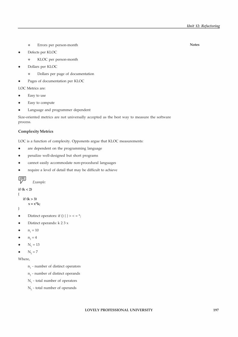
LOVELY PROFESSIONAL UNIVERSITY 197
Unit 12: Refactoring
Notes� Errors per person-month
� Defects per KLOC
� KLOC per person-month
� Dollars per KLOC
� Dollars per page of documentation
� Pages of documentation per KLOC
LOC Metrics are:
� Easy to use
� Easy to compute
� Language and programmer dependent
Size-oriented metrics are not universally accepted as the best way to measure the softwareprocess.
Complexity Metrics
LOC is a function of complexity. Opponents argue that KLOC measurements:
� are dependent on the programming language
� penalize well-designed but short programs
� cannot easily accommodate non-procedural languages
� require a level of detail that may be difficult to achieve
Example:
if (k < 2){
if (k > 3)x = x*k;
}
� Distinct operators: if () { } > < = *;
� Distinct operands: k 2 3 x
� n1 = 10
� n2 = 4
� N1 = 13
� N2 = 7
Where,
n1 - number of distinct operators
n2 - number of distinct operands
N1 - total number of operators
N2 - total number of operands

198 LOVELY PROFESSIONAL UNIVERSITY
Principles of Software Engineering
Notes Self Assessment
Fill in the blanks:
10. Three commonly used software metrics are coupling, cohesion, and …………………….
11. …………………… measures the strength of the connections between the software modulesthat comprise a particular system to quantify the dependencies between the modules.
12. …………………… measures how strongly the elements of each module are related to eachother.
13. McCabe’s Cyclomatic Complexity is the number of …………………… through the module.
14. …………………… and …………………… have a significant impact on both the quality ofthe software and the effort required fixing errors in the software.
15. Modules with …………………… cohesion implement more than one function.
12.4 Summary
� Refactoring is a disciplined technique for restructuring an existing body of code, alteringits internal structure without changing its external behavior.
� Code refactoring is the process of changing a computer program’s source code withoutmodifying its external functional behavior, in order to improve some of the non-functionalattributes of the software.
� One approach to refactoring is to improve the structure of source code at one point andthen extend the same changes systematically to all applicable references throughout theprogram.
� Refactoring is usually motivated by noting a code’s smell.
� Once we have decomposed a refactoring implementation both in terms of its functionalityand in terms of the object language, we need to find a suitable verification method toprove correctness of the components.
� We use software metrics to try to quantify particular characteristics of software systems,such as quality, maintainability, or reliability.
� The final metric, which is probably the most commonly used metric of those discussedhere, is McCabe’s Cyclomatic Complexity.
12.5 Keywords
Code Refactoring: Code refactoring is a “disciplined technique for restructuring an existingbody of code, altering its internal structure without changing its external behavior”, undertakenin order to improve some of the nonfunctional attributes of the software.
Duplicate Code: Duplicate code is a computer programming term for a sequence of source codethat occurs more than once, either within a program or across different programs owned ormaintained by the same entity.
Extract Method: Extract Method is a refactoring operation that provides an easy way to create anew method from a code fragment in an existing member.
Move Method: A method is, or will be, using or used by more features of another class than theclass on which it is defined.

LOVELY PROFESSIONAL UNIVERSITY 199
Unit 12: Refactoring
NotesRefactoring: Refactoring is a kind of reorganization. Technically, it comes from mathematicswhen you factor an expression into equivalence – the factors are cleaner ways of expressing thesame statement.
12.6 Review Questions
1. What is refactoring? Discuss the approach to refactoring.
2. Write down the meaning and concept of code refactoring.
3. Discuss the benefits of refactoring.
4. Write down the two general categories of benefits to the activity of refactoring.
5. “Refactoring is a huge aid in untangling production code without breaking it”. Elucidate.
6. Give reasons to refactor code.
7. Write short note on:
(a) Leveraging Refactoring
(b) Properties of Refactoring’s
(c) Extract method
(d) Move method
8. Discuss the verification in refactoring.
9. Explain the three commonly used software metrics.
10. Discuss about the size of metrics.
Answers: Self Assessment
1. Code Refactoring 2. Refactoring
3. Code smell 4. Nested
5. Case statements 6. Patterns
7. True 8. True
9. True 10. McCabe’s Cyclomatic Complexity
11. Coupling 12. Cohesion
13. Linearly independent paths 14. Coupling, cohesion
15. Low
12.7 Further Readings
Books Rajib Mall, Fundamentals of Software Engineering, 2nd Edition, PHI.
Richard Fairpy, Software Engineering Concepts, Tata McGraw Hill, 1997.
R.S. Pressman, Software Engineering – A Practitioner’s Approach, 5th Edition, TataMcGraw Hill Higher education.
Sommerville, Software Engineering, 6th Edition, Pearson Education

200 LOVELY PROFESSIONAL UNIVERSITY
Principles of Software Engineering
Notes
Online links www.cs.tau.ac.il/~apartzin/systems/7_refactoring.pdf
jaoo.dk/jaoo1999/schedule/MartinFowlerRefractoring.pdf
martinfowler.com/books/refactoring.html
www.4shared.com/office/.../Refactoring_-_Improving_the_De.html
LOVELY PROFESSIONAL UNIVERSITY 201
Unit 13: Software Testing-I
NotesUnit 13: Software Testing-I
CONTENTS
Objectives
Introduction
13.1 Fundamentals of Testing
13.1.1 Benefits of Testing
13.1.2 Testing Principles
13.1.3 Testing Objectives
13.1.4 Testability
13.1.5 Error, Fault, Failure
13.2 Test Oracles
13.3 Test Cases and Criteria
13.4 Black Box Testing
13.4.1 Equivalence Partitioning
13.4.2 Boundary Value Analysis
13.5 White Box Testing
13.5.1 Basis Path Testing
13.5.2 Control Flow Based Testing
13.5.3 Data Flow Testing
13.5.4 Loop Testing
13.6 Summary
13.7 Keywords
13.8 Review Questions
13.9 Further Readings
Objectives
After studying this unit, you will be able to:
� Discuss the fundamentals of Testing
� Explain the test oracles
� Understand the test cases and criteria
� Discuss about black box testing
� Explain about the white box testing
202 LOVELY PROFESSIONAL UNIVERSITY
Principles of Software Engineering
Notes Introduction
Software testing is a critical element of software quality assurance and resents the final reviewof specification, design, and code. The source-code once generated needs to be tested for bugsand defects to get rid of maximum errors before the software is sent to the customer. Test casesare designed with an aim to find errors. During initial stages of testing, a software engineerperforms all the tests. However, at later stages a specialist may be involved. Tests must beconducted to find the highest possible number of errors, must be done systematically and in adisciplined way. Testing involves checking both the internal program logic and the softwarerequirements.
13.1 Fundamentals of Testing
Testing software can be considered as the only destructive (psychologically) step in the entirelife cycle of software production. Although all the initial activities aimed at building a product,the testing is done to find errors in software.
13.1.1 Benefits of Testing
The following are the benefits of testing:
� It reveals the errors in the software.
� It ensures that software is functioning as per specifications and it meets all the behavioralrequirements as well.
� The data obtained during testing is indicative of software reliability and quality as awhole.
� It indicates presence of errors and not absence of errors.
13.1.2 Testing Principles
Before coming up with ways to design efficient test cases, one must understand the basic principlesof testing:
� Test Cases must be Traceable to Requirements: Because software testing reveals errors, so,the severe defects will be those that prevent the program from acting as per the customer’sexpectations and requirements.
� Test Planning must be done before Beginning Testing: Test planning can begin soon afterthe requirements specification is complete and the detailed test cases can be developedafter the design has been fixed.
� Pareto Principle Applies to Software Testing: Pareto principle states that 80 percent of theuncovered errors during testing will likely be traceable to 20 percent of all the programcomponents. Thus, the main aim is to thoroughly test these 20 percent components afteridentifying them.
� Testing should begin with Small and End in Large: The initial tests planned and carried outare usually individual components and as testing progresses the aim shifts to find errorsin integrated components of the system as whole rather than individual components.
� Exhaustive Testing is Impossible: For a normal sized program the number of permutationsof execution paths is very huge. Thus, it is impossible to execute all the combinationspossible. Thus, while designing a test case it should be kept in minds that it must cover themaximum logic and the component-level design.
LOVELY PROFESSIONAL UNIVERSITY 203
Unit 13: Software Testing-I
Notes� Efficient Testing can be Conducted only by a Third Party: The highest probability offinding errors exists when the testing is not carried by the party which develops thesystem.
13.1.3 Testing Objectives
Various testing objectives are:
� Executing a program in order to find errors.
� A good test case is the one that has a high probability of finding an undiscovered error.
� A successful test is the one that reports an as – yet undiscovered error.
13.1.4 Testability
A program developed should be testable i.e. it should be possible to test the program. Thetestability of a program can be measured in terms of few properties like: operability,observability, controllability, decomposability, simplicity, stability, understandability, etc.
!Caution The test also, must also comply with the characteristics of a good test case.
These characteristics are mentioned here:
� The probability of finding error should be high. In order to achieve this, tester mustunderstand the actual functionality of the software and think of a suitable condition thatcan lead to failure of the software.
� A test case must be non-redundant. Because the testing time and resources are limited, itwill waste a lot of time to conduct the same test again and again. Every test must have adistinct purpose.
� A test case must be of the best quality. In a group of similar test cases, the one that coversthe maximum scenarios to uncover maximum errors should only be used.
� A good test case should neither be too simple nor too complex. A complex test thatincludes several other tests can lead to masking of errors. Thus, each test case should beexecuted separately.
Did u know? Testing is an extremely important, although often neglected, activity in thesoftware quality initiative.
13.1.5 Error, Fault, Failure
Many people associate quality of a software system with a suggestion that some softwaretroubles are estimated to happen (or not). And in the case if such troubles do occur, the negativeinfluence is estimated to be minimal. Clue to the correctness perspective of software quality isin the concept of failure, fault, and error.
Error
An error is a person act that generates an erroneous result. The term error is used in twodifferent ways. It refers to the discrepancy between a computed, observed, or measured value
204 LOVELY PROFESSIONAL UNIVERSITY
Principles of Software Engineering
Notes and the true, specified, or theoretically correct value. That is error refers to the difference betweenthe actual output of software and the correct output. The term error is a discrepancy between acomputed, observed, or measured value or condition and the true, specified, or theoreticallycorrect value or condition
Fault
Fault is a condition that causes a system to fail in performing its required function. It refers to anunderlying condition within software that causes failure to happen. A fault is the basic reasonfor software malfunction and is synonymous with the commonly used term bug. It is an incorrectstep, process, or data definition in a computer program which causes the program to perform inan unintended or unanticipated manner.
Failure
Failure is the inability of a system or component to perform a required function according to itsspecifications. It refers to a behavioral deviation from the user wants or the product specification.A software failure occurs if the behavior of the software is different from the specified behavior.
Task Make difference between Error, Fault, and Failure.
Self Assessment
Fill in the blanks:
1. …………………… can be considered as the only destructive (psychologically) step in theentire life cycle of software production.
2. …………………… refers to the discrepancy between a computed, observed, or measuredvalue and the true, specified, or theoretically correct value.
3. …………………… refers to an underlying condition within software that causes failure tohappen.
4. …………………… refers to a behavioral deviation from the user wants or the productspecification.
13.2 Test Oracles
An oracle is a mechanism for determining whether the program has passed or failed a test. Allsoftware testing methods depend on the availability of an oracle, that is, some method forchecking whether the system under test has behaved correctly on a particular execution.
Oracles are either based on a program specification, or are a (perhaps very incomplete)specification of intended behavior. Some oracles, particularly those expressed in assertionlanguages embedded in program text, describe acceptable behaviors entirely at animplementation level. Others are derived from or associated with external, usually more abstractspecifications or models. In either case, a key problem for test oracles is bridging the gapbetween abstract specifications and efficiently checkable properties of concrete executionsequences. Common problems that have been addressed in different ways include evaluation ofpredicates involving quantification over large or infinite sets and predicates relating values atdifferent points in execution history. The survey is not encyclopedic, but discusses representativeexamples of the main approaches and tactics for solving common problems.

LOVELY PROFESSIONAL UNIVERSITY 205
Unit 13: Software Testing-I
NotesA complete oracle would have three capabilities and would carry them out perfectly:
� A generator, to provide predicted or expected results for each test.
� A comparator, to compare predicted and obtained results.
� An evaluator, to determine whether the comparison results are sufficiently close to be apass.
One of the key problems with oracles is that they can only address a small subset of the inputsand outputs actually associated with any test. The tester might intentionally set the values ofsome variables, but the entire program’s other variables have values too. Configuration settings,amount of available memory, and program options can also affect the test results. As a result,our evaluation of the test results (that we look at) in terms of the test inputs (that we setintentionally) is based on incomplete data, and may be incorrect.
Any of the oracle capabilities may be automated.
Example: We might generate predictions for a test from previous test results on thisprogram, from the behavior of a previous release of this program or a competitor’s program,from a standard function or from a custom model.
We might generate these by hand, by a tool that feeds input to the reference program andcaptures output or by something that combines automated and manual testing. We might insteadgenerate predictions from specifications, advertised claims, regulatory requirements or othersources of information that require a human to evaluate the information in order to generate theprediction.
Self Assessment
Fill in the blanks:
5. An …………………… is a mechanism for determining whether the program has passed orfailed a test.
6. Oracles are either based on a program specification, or are a (perhaps very incomplete)specification of …………………….
13.3 Test Cases and Criteria
A test case is a set of conditions or variables under which a tester will determine whether asystem under test satisfies requirements or works correctly. The process of developing test casescan also help find problems in the requirements or design of an application. Having test casesthat are good at revealing the presence of faults is central to successful testing. Ideally, we wouldlike to determine a set of test cases such that successful execution of all of them implies that thereare no errors in the program. This ideal goal cannot usually be achieved due to practical andtheoretical constraints.
As each test case costs money, effort is needed to generate the test case, machine time is neededto execute the program for that test case, and more effort is needed to evaluate the results.
Therefore, we would also like to minimize the number of test cases needed to detect errors.These are the two fundamental goals of a practical testing activity – maximize the number oferrors detected and minimize the number of test cases. With selecting test cases the primaryobjectives is to ensure that if there is an error or fault in the program, it is exercised by one of thetest cases.
206 LOVELY PROFESSIONAL UNIVERSITY
Principles of Software Engineering
Notes An ideal test case set is one that succeeds (meaning that its execution reveals no errors) only ifthere are no errors in the program. For this test selection criterion can be used. There are twoaspects of test case selection – specifying a criterion for evaluating a set of test cases, and generatinga set of test cases that satisfy a given criterion.
There are two fundamental properties for a testing criterion: reliability and validity. A criterionis reliable if all the sets that satisfy the criterion detect the same errors. A criterion is valid if forany error in the program there is some set satisfying the criterion that will reveal the error.Some axioms capturing some of the desirable properties of test criteria have been proposed. Thefirst axiom is the applicability axiom, which states that for every program there exists a test setT that satisfies the criterion.
This is clearly desirable for a general-purpose criterion: a criterion that can be satisfied only forsome types of programs is of limited use in testing. The anti-extensionality axiom states thatthere are programs P and Q, both of which implement the same specifications, such that a test setT satisfies the criterion for P but does not satisfy the criterion for Q.
Notes This axiom ensures that the program structure has an important role to play indeciding the test cases.
The anti-decomposition axiom states that there exists a program P and its component Q such thata test case set T satisfies the criterion for P and T1 is the set of values that variables can assume onentering Q for some test case in T and T1 does not satisfy the criterion for Q. Essentially, theaxiom says that just because the criterion is satisfied for the entire program, it does not meanthat the criterion has been satisfied for its components.
The anti-composition axiom states that there exist program P and Q such that T satisfies thecriterion for P and the outputs of P for T satisfy the criterion for Q, but T does not satisfy thecriterion for the parts P and Q does not imply that the criterion has been satisfied by the programcomprising P, Q. It is very difficult to get a criterion that satisfies even these axioms. This islargely due to the fact that a program may have paths that are infeasible, and one cannotdetermine these infeasible paths algorithmically as the problem is undesirable.
Self Assessment
State whether the following statements are true or false:
7. A test case is a set of conditions or variables under which a tester will determine whethera system under test satisfies requirements or works correctly.
8. An ideal test case set is one that succeeds (meaning that its execution reveals no errors)only if there are no errors in the program.
9. There are two fundamental properties for a testing criterion: reliability and validity.
13.4 Black Box Testing
Black-box testing, also called behavioral testing, focuses on the functional requirements of thesoftware. That is, black-box testing enables the software engineer to derive sets of input conditionsthat will fully exercise all functional requirements for a program. Black-box testing is not analternative to white-box techniques. Rather, it is a complementary approach that is likely touncover a different class of errors than white-box methods.
LOVELY PROFESSIONAL UNIVERSITY 207
Unit 13: Software Testing-I
NotesBlack-box testing attempts to find errors in the following categories:
1. Incorrect or missing functions
2. Interface errors
3. Errors in data structures or external data base access
4. Behavior or performance errors
5. Initialization and termination errors.
By applying black-box techniques, we derive a set of test cases that satisfy the following criteria:
1. Test cases that reduce, by a count that is greater than one, the number of additional testcases that must be designed to achieve reasonable testing.
2. Test cases that tell us something about the presence or absence of classes of errors, ratherthan an error associated only with the specific test at hand.
13.4.1 Equivalence Partitioning
Equivalence partitioning is a black-box testing method that divides the input domain of aprogram into classes of data from which test cases can be derived. An ideal test case single-handedly uncovers a class of errors that might otherwise require many cases to be executedbefore the general error is observed.
Equivalence partitioning strives to define a test case that uncovers classes of errors, therebyreducing the total number of test cases that must be developed.
Test case design for equivalence partitioning is based on an evaluation of equivalence classes foran input condition. Using concepts introduced in the preceding section, if a set of objects can belinked by relationships that are symmetric, transitive, and reflexive, an equivalence class ispresent.
An equivalence class represents a set of valid or invalid states for input conditions. Typically, aninput condition is a specific numeric value, a range of values, a set of related values, or a Booleancondition. Equivalence classes may be defined according to the following guidelines:
1. If an input condition specifies a range, one valid and two invalid equivalence classes aredefined.
2. If an input condition requires a specific value, one valid and two invalid equivalenceclasses are defined.
3. If an input condition specifies a member of a set, one valid and one invalid equivalenceclass are defined.
4. If an input condition is Boolean, one valid and one invalid class are defined.
13.4.2 Boundary Value Analysis
Boundary value analysis is a test case design technique that complements equivalencepartitioning. Rather than selecting any element of an equivalence class, BVA leads to the selectionof test cases at the “edges” of the class. Rather than focusing solely on input conditions, BVAderives test cases from the output domain as well
Guidelines for BVA are similar in many respects to those provided for equivalence partitioning:
1. If an input condition specifies a range bounded by values a and b, test cases should bedesigned with values a and b and just above and just below a and b.
208 LOVELY PROFESSIONAL UNIVERSITY
Principles of Software Engineering
Notes 2. If an input condition specifies a number of values, test cases should be developed thatexercise the minimum and maximum numbers.
!Caution Values just above and below minimum and maximum are also tested.
3. Apply guidelines 1 and 2 to output conditions.
Example: Assume that a temperature vs. pressure table is required as output from anengineering analysis program.
Test cases should be designed to create an output report that produces the maximum (andminimum) allowable number of table entries.
4. If internal program data structures have prescribed boundaries (e.g., an array has a definedlimit of 100 entries), be certain to design a test case to exercise the data structure at itsboundary.
Most software engineers intuitively perform BVA to some degree. By applying these guidelines,boundary testing will be more complete, thereby having a higher likelihood for error detection.
Self Assessment
Fill in the blanks:
10. Black-box testing, also called …………………….
11. Black-box testing is not an alternative to …………………… techniques.
12. …………………… is a black-box testing method that divides the input domain of a programinto classes of data from which test cases can be derived.
13. An …………………… represents a set of valid or invalid states for input conditions.
14. …………………… analysis is a test case design technique that complements equivalencepartitioning.
13.5 White Box Testing
White box-testing referred to as glass box test can be defined as a test case design method whichemploys control structure of procedural design in order to derive test cases. Such kind of testing,software engineer can be deriving test cases which:
1. Guarantee that all independent paths within a module have been exercised at least once,
2. Exercise all logical decisions on their true and false sides
3. Execute all loops at their boundaries and within their operational bounds
4. Exercise internal data structures to ensure their validity.
The arguments mentioned below provide us with the reason for conducting white-box tests.
� Logic errors and incorrect assumptions are inversely proportional to the probability thata program path will be executed
� We often believe that a logical path is not likely to be executed when, in fact, it may beexecuted on a regular basis
� Typographical errors are random

LOVELY PROFESSIONAL UNIVERSITY 209
Unit 13: Software Testing-I
NotesThe different types of White Box testing are discussed below:
13.5.1 Basis Path Testing
Basis path testing is a white-box testing technique, proposed by Tom McCabe which enables thetest case designer to derive a logical complexity measure of a procedural design and use thismeasure as a guide for defining a basis set of execution paths. Test cases derived to exercise thebasis set are guaranteed to execute every statement in the program at least one time duringtesting.
Flow Graph Notation
Before the basis path method can be introduced, a simple notation for the representation ofcontrol flow, called a flow graph or program graph must be introduced. The flow graph depictslogical control flow using the notation illustrated in Figure 13.1. Each structured construct has acorresponding flow graph symbol.
Cyclomatic Complexity
Cyclomatic complexity is software metric that provides a quantitative measure of the logicalcomplexity of a program. When used in the context of the basis path testing method, the valuecomputed for Cyclomatic complexity defines the number of independent paths in the basis setof a program and provides us with an upper bound for the number of tests that must be conductedto ensure that all statements have been executed at least once.
Driving Test Cases
The basis path testing method can be applied to a procedural design or to source code. Theprocedure average, depicted in PDL in Figure 13.2 can be used as an example to illustrate eachstep in the test case design method. The following steps can be applied to derive the basis set:
1. Using the Design or Code as a Foundation, Draw a Corresponding Flow Graph: A flowgraph is created using the symbols and construction rules. Referring to the PDL for averagein Figure 13.2, a flow graph is created by numbering those PDL statements that will bemapped into corresponding flow graph nodes. The corresponding flow graph is in Figure13.1.
2. Determine the Cyclomatic Complexity of the Resultant Flow Graph: The cyclomaticcomplexity, V(G), is determined by applying the algorithms.
Figure 13.1: Flow Graph Notation
210 LOVELY PROFESSIONAL UNIVERSITY
Principles of Software Engineering
Notes
Notes It should be noted that V(G) can be determined without developing a flow graphby counting all conditional statements in the PDL and adding 1.
Referring to Figure 13.2,
V(G) = 6 regions
V(G) = 17 edges _ 13 nodes + 2 = 6
V(G) = 5 predicate nodes + 1 = 6
3. Determine a Basis Set of Linearly Independent Paths: The value of V(G) provides thenumber of linearly independent paths through the program control structure. In the caseof procedure average, we expect to specify six
paths:
path 1: 1-2-10-11-13
path 2: 1-2-10-12-13
path 3: 1-2-3-10-11-13
path 4: 1-2-3-4-5-8-9-2-. . .
path 5: 1-2-3-4-5-6-8-9-2-. . .
path 6: 1-2-3-4-5-6-7-8-9-2-. . .
The ellipsis (. . .) following paths 4, 5, and 6 indicates that any path through the remainderof the control structure is acceptable. It is often worthwhile to identify predicate nodes asan aid in the derivation of test cases. In this case, nodes 2, 3, 5, 6, and 10 are predicate nodes.
4. Prepare Test Cases that will Force Execution of each Path in the Basis Set: Data should bechosen so that conditions at the predicate nodes are appropriately set as each path is tested.Test cases that satisfy the basis set just described are:
Path 1 Test Case:
value(k) = valid input, where k < i for 2 d” i d” 100
value(i) = _999 where 2 d” i d” 100
Expected Results: Correct average based on k values and proper totals.
Notes Path 1 cannot be tested stand-alone but must be tested as part of path 4, 5, and 6tests.
Path 2 Test Case:
value(1) = _999
Expected Results: Average = _999; other totals at initial values.
Path 3 Test Case:
Attempt to process 101 or more values.
First 100 values should be valid.
Expected Results: Same as test case 1.

LOVELY PROFESSIONAL UNIVERSITY 211
Unit 13: Software Testing-I
NotesPath 4 Test Case:
value(i) = valid input where i < 100
value(k) < minimum where k < i
Expected Results: Correct average based on k values and proper totals.
Path 5 Test Case:
value(i) = valid input where i < 100
value(k) > maximum where k <= i
Expected Results: Correct average based on n values and proper totals.
Path 6 Test Case:
value(i) = valid input where i < 100
Expected Results: Correct average based on n values and proper totals.
Each test case is executed and compared to expected results. Once all test cases have beencompleted, the tester can be sure that all statements in the program have been executed atleast once.
Figure 13.2: PDL for Test Case Design with Nodes Identified

212 LOVELY PROFESSIONAL UNIVERSITY
Principles of Software Engineering
Notes
13.5.2 Control Flow Based Testing
It is a white box testing technique to find bug is control flow testing. Control flow testingapplies to almost all software and is effective for most software. It is a structural testing strategythat uses the program’s control flow as a model control flow testing favour more but simplerpaths over complicated but fewer paths. Researches shows that control flow testing catchesabout 50% of all bugs during unit testing (unit testing is dominated by control flow testing).Control flow testing is more effective for unstructured code rather than structured code. Mostbugs can result in control flow errors and therefore misbehaviour that could be caught bycontrol flow testing. Control flow bugs are not as common as they used to be as they areminimize because of structured programming languages. Some of the limitations of controlflow testing are:
1. Control flow testing cannot catch all initialization mistakes.
2. Specification mistake are not caught by control flow testing.
3. It’s unlikely to find missing paths and features if the program and the model on which thetests are based are done by the same person.
The adequacy of the test cases measured with a metric called coverage (coverage is a measure ofthe completeness of the set of test cases). Now, we will define various coverage methods.
Statement Coverage
Statement coverage is a measure of the percentage of statements that have been executed by testcases. Anything less than 100% statement coverage means that not all lines of code have been
Figure 13.3: Flow Graph for the Procedure Average

LOVELY PROFESSIONAL UNIVERSITY 213
Unit 13: Software Testing-I
Notesexecuted. We can achieve statement coverage by identifying cyclomatic number an executingthis minimum set of test cases. Measure benefit of statement coverage is that it is greatly able toisolate the portion of code, which could not be executed. Since it tends to become expensive, thedeveloper chose a better testing technique called branch coverage or decision coverage.
Branch Coverage
A stronger logic coverage criterion is known as branch coverage or decision coverage. Branchcoverage or decision coverage is a measure of the percentage of the decision point of the programhave been evaluated as both true and false in test cases.
Example: Branch coverage-DO statements, IF statements and multi-way GOTOstatements. Branch coverage is usually shown to satisfy statement coverage. By 100% branchcoverage we mean that every control flow graph is traversed.
Condition Coverage
A criterion which is stronger than decision coverage is condition coverage. It is a measure ofpercentage of Boolean sub-expressions of the program that have been evaluated as both true andfalse outcome in test cases.
13.5.3 Data Flow Testing
The data flow testing method selects test paths of a program according to the locations ofdefinitions and uses of variables in the program. A number of data flow testing strategies havebeen studied and compared.
To illustrate the data flow testing approach, assume that each statement in a program is assigneda unique statement number and that each function does not modify its parameters or globalvariables. For a statement with S as its statement number,
DEF(S) = {X | statement S contains a definition of X}
USE(S) = {X | statement S contains a use of X}
If statement S is an if or loop statement, its DEF set is empty and its USE set is based on thecondition of statement S. The definition of variable X at statement S is said to be live at statementS’ if there exists a path from statement S to statement S’ that contains no other definition of X.
A definition-use (DU) chain of variable X is of the form [X, S, S’], where S and S’ are statementnumbers, X is in DEF(S) and USE(S’), and the definition of X in statement S is live at statementS’.
One simple data flow testing strategy is to require that every DU chain be covered at least once.We refer to this strategy as the DU testing strategy. It has been shown that DU testing does notguarantee the coverage of all branches of a program. However, a branch is not guaranteed to becovered by DU testing only in rare situations such as if-then-else constructs in which the then parthas no definition of any variable and the else part does not exist. In this situation, the else branchof the if statement is not necessarily covered by DU testing.
Moreover the Data flow testing strategies are useful for selecting test paths of a program containingnested if and loop statements.

214 LOVELY PROFESSIONAL UNIVERSITY
Principles of Software Engineering
Notes 13.5.4 Loop Testing
Loop testing is a white-box testing technique that focuses exclusively on the validity of loopconstructs. Four different classes of loops can be defined given in Figure 13.4:
� Simple loops
� Nested loops
� Concatenated loops
� Unstructured loops
1. Simple Loops: The following set of tests can be applied to simple loops, where n is themaximum number of allowable passes through the loop:
(a) Skip the loop entirely.
(b) Only one pass through the loop.
(c) Two passes through the loop.
(d) m passes through the loop where m < n.
(e) n _1, n, n + 1 passes through the loop.
2. Nested Loops: If you were to extend the test approach for simple loops to nested loops, thenumber of possible tests would grow geometrically as the level of nesting increases. Thiswould result in an impractical number of tests. Beizer suggests an approach that will helpto reduce the number of tests:
(a) Start at the innermost loop. Set all other loops to minimum values.
Figure 13.4: Loops Classes

LOVELY PROFESSIONAL UNIVERSITY 215
Unit 13: Software Testing-I
Notes(b) Conduct simple loop tests for the innermost loop while holding the outer loops attheir minimum iteration parameter (e.g., loop counter) values. Add other tests forout-of-range or excluded values.
(c) Work outward, conducting tests for the next loop, but keeping all other outer loopsat minimum values and other nested loops to “typical” values.
(d) Continue until all loops have been tested.
3. Concatenated Loops: Concatenated loops can be tested using the approach defined forsimple loops, if each of the loops is independent of the other. However, if two loops areconcatenated and the loop counter for loop 1 is used as the initial value for loop 2, then theloops are not independent. When the loops are not independent, the approach applied tonested loops is recommended.
4. Unstructured Loops: Whenever possible, this class of loops should be redesigned to reflectthe use of the structured programming constructs.
Self Assessment
Fill in the blanks:
15. …………………… referred to as glass box test can be defined as a test case design methodwhich employs control structure of procedural design in order to derive test cases.
16. …………………… complexity is software metric that provides a quantitative measure ofthe logical complexity of a program.
13.6 Summary
� Tests must be conducted to find the highest possible number of errors, must be donesystematically and in a disciplined way.
� Testing software can be considered as the only destructive (psychologically) step in theentire life cycle of software production.
� A program developed should be testable i.e. it should be possible to test the program.
� An oracle is a mechanism for determining whether the program has passed or failed a test.
� One of the key problems with oracles is that they can only address a small subset of theinputs and outputs actually associated with any test.
� A test case is a set of conditions or variables under which a tester will determine whethera system under test satisfies requirements or works correctly.
� There are two fundamental properties for a testing criterion: reliability and validity.
� Black-box testing, also called behavioral testing, focuses on the functional requirementsof the software.
� Equivalence partitioning is a black-box testing method that divides the input domain of aprogram into classes of data from which test cases can be derived.
� White box-testing referred to as glass box test can be defined as a test case design methodwhich employs control structure of procedural design in order to derive test cases.
216 LOVELY PROFESSIONAL UNIVERSITY
Principles of Software Engineering
Notes 13.7 Keywords
Basis Path Testing: It allows the design and definition of a basis set of execution paths.
Black-box Testing: It refers to tests that are conducted at the software interfaces; it mainlyfocuses on the functional requirements of the software.
Boundary Value Analysis: Boundary value analysis is a test case design technique thatcomplements equivalence partitioning.
Data Flow Testing: The data flow testing method selects test paths of a program according to thelocations of definitions and uses of variables in the program.
Equivalence Class: An equivalence class represents a set of valid or invalid states for inputconditions.
Equivalence Partitioning: Equivalence partitioning is a black-box testing method that dividesthe input domain of a program into classes of data from which test cases can be derived.
Error: An error is a person act that generates an erroneous result.
Failure: Failure is the inability of a system or component to perform a required function accordingto its specifications.
Fault: Fault is a condition that causes a system to fail in performing its required function.
Loop Testing: Loop testing is a white-box testing technique that focuses exclusively on thevalidity of loop constructs.
Oracle: An oracle is a mechanism for determining whether the program has passed or failed atest.
Software Testing: Software testing is an investigation conducted to provide stakeholders withinformation about the quality of the product or service under test.
Statement Coverage: Statement coverage is a measure of the percentage of statements that havebeen executed by test cases.
Structural Testing: It examine source code and analysis what is present in the code.
Test Case: A test case is a set of conditions or variables under which a tester will determinewhether a system under test satisfies requirements or works correctly.
White-box Testing: It works on the principle of closely monitoring the procedural details of thesoftware.
13.8 Review Questions
1. What are the fundamentals of software testing?
2. Explain the benefits and objectives of testing.
3. Enumerate the various principles of testing.
4. What are the various testing objectives?
5. Define testability.
6. What is oracle? What are the problems with oracles?
7. Define test case. Discuss about the test cases & its various criteria.
8. Briefly explain the Black-box testing. Discuss about equivalence partitioning.
LOVELY PROFESSIONAL UNIVERSITY 217
Unit 13: Software Testing-I
Notes9. Elaborate the boundary value analysis.
10. Describe about White box-testing.
11. What are the different types of White Box testing?
12. Discuss about control flow based testing.
13. Explain the data flow testing.
14. What are the four different classes of loops?
15. Write short notes on:
(a) Base Path Testing
(b) Control Structure Testing
(c) Black-Box Testing
(d) Equivalence Class Testing
(e) White Box Testing
Answers: Self Assessment
1. Testing software 2. Error
3. Fault 4. Failure
5. Oracle 6. Intended behavior
7. True 8. True
9. True 10. Behavioral testing
11. White-box 12. Equivalence partitioning
13. Equivalence class 14. Boundary value
15. White box-testing 16. Cyclomatic
13.9 Further Readings
Books Rajib Mall, Fundamentals of Software Engineering, 2nd Edition, PHI.
Richard Fairpy, Software Engineering Concepts, Tata McGraw Hill, 1997.
R.S. Pressman, Software Engineering – A Practitioner’s Approach, 5th Edition, TataMcGraw Hill Higher education.
Sommerville, Software Engineering, 6th Edition, Pearson Education
Online links www.guru99.com/software-testing.html
www.ece.cmu.edu/~koopman/des_s99/sw_testing/
www.softwarequalitymethods.com/Papers/OracleTax.pdf
se.fsksm.utm.my/.../IST-AutomatedFrameworkSoftTestOracle-FPage.pdf

218 LOVELY PROFESSIONAL UNIVERSITY
Principles of Software Engineering
Notes Unit 14: Software Testing-II
CONTENTS
Objectives
Introduction
14.1 Levels of Testing
14.1.1 Unit Testing
14.1.2 Integration Testing
14.1.3 System Testing
14.1.4 Acceptance Testing
14.2 Test Plan
14.3 Test Case Specifications
14.4 Execution and Analysis
14.5 Logging and Tracking
14.5.1 Earned Value Analysis
14.6 Metrics
14.6.1 Failure Data Estimation
14.6.2 Parameter Estimation
14.7 Summary
14.8 Keywords
14.9 Review Questions
14.10 Further Readings
Objectives
After studying this unit, you will be able to:
� Discuss various levels of testing
� Discuss about test plan
� Explain the test case specifications
� Identify the execution and analysis
� Understand logging and tracking
� Discuss about metrics
Introduction
Software testing is an investigation conducted to provide stakeholders with information aboutthe quality of the product or service under test. Software testing can also provide an objective,independent view of the software to allow the business to appreciate and understand the risks of

LOVELY PROFESSIONAL UNIVERSITY 219
Unit 14: Software Testing-II
Notessoftware implementation. Test techniques include, but are not limited to, the process of executinga program or application with the intent of finding software bugs (errors or other defects).Testing is the process of evaluating a system or its component(s) with the intent to find thatwhether it satisfies the specified requirements or not. Testing is executing a system in order toidentify any gaps, errors or missing requirements in contrary to the actual desire or requirements.
14.1 Levels of Testing
The levels of testing are discussed below:
14.1.1 Unit Testing
The first level of testing is called unit testing. Unit testing focuses on verification of individualunits or modules of software. Using the design, important control paths are identified and testedto find errors within the module boundary.
Did u know? The unit testing is white-box oriented and can be conducted in parallel formultiple components.
It involves running a module in isolation from the rest of the software by preparing test casesand comparing the actual results with the expected results as specified by the specifications anddesign. One of its purposes is to find and remove as many errors in the software as practical.
Advantages of Unit Testing
� The size of a module is small enough to locate errors comparatively easily.
� The module is small enough to be able to test it in an exhaustive fashion.
� Confusing interactions of multiple errors in different parts of the software are eliminated.
However, there are problems associated with running a program in isolation. The biggestproblem is how to run a module in isolation, without anything to call it and without anythingbeing called by it. One approach is to build an appropriate routine to call it and the stubs to becalled by it or to simply insert output statements.
Figure 14.1: Unit Testing
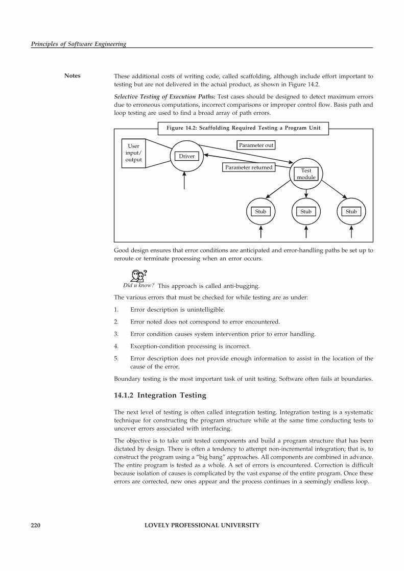
220 LOVELY PROFESSIONAL UNIVERSITY
Principles of Software Engineering
Notes These additional costs of writing code, called scaffolding, although include effort important totesting but are not delivered in the actual product, as shown in Figure 14.2.
Selective Testing of Execution Paths: Test cases should be designed to detect maximum errorsdue to erroneous computations, incorrect comparisons or improper control flow. Basis path andloop testing are used to find a broad array of path errors.
Userinput/output
Driver
Testmodule
StubStub Stub
Parameter out
Parameter returned
Good design ensures that error conditions are anticipated and error-handling paths be set up toreroute or terminate processing when an error occurs.
Did u know? This approach is called anti-bugging.
The various errors that must be checked for while testing are as under:
1. Error description is unintelligible.
2. Error noted does not correspond to error encountered.
3. Error condition causes system intervention prior to error handling.
4. Exception-condition processing is incorrect.
5. Error description does not provide enough information to assist in the location of thecause of the error.
Boundary testing is the most important task of unit testing. Software often fails at boundaries.
14.1.2 Integration Testing
The next level of testing is often called integration testing. Integration testing is a systematictechnique for constructing the program structure while at the same time conducting tests touncover errors associated with interfacing.
The objective is to take unit tested components and build a program structure that has beendictated by design. There is often a tendency to attempt non-incremental integration; that is, toconstruct the program using a “big bang” approaches. All components are combined in advance.The entire program is tested as a whole. A set of errors is encountered. Correction is difficultbecause isolation of causes is complicated by the vast expanse of the entire program. Once theseerrors are corrected, new ones appear and the process continues in a seemingly endless loop.
Figure 14.2: Scaffolding Required Testing a Program Unit

LOVELY PROFESSIONAL UNIVERSITY 221
Unit 14: Software Testing-II
NotesIncremental integration is the antithesis of the big bang approach. The program is constructedand tested in small increments, where errors are easier to isolate and correct; interfaces are morelikely to be tested completely; and a systematic test approach may be applied.
Top-down Integration
Top-down integration testing is an incremental approach to construction of program structure.Modules are integrated by moving downward through the control hierarchy, beginning withthe main control module. Modules subordinate to the main control module are incorporatedinto the structure in either a depth-first or breadth-first manner.
Referring to Figure 14.3, depth-first integration would integrate all components on a majorcontrol path of the structure. Selection of a major path is somewhat arbitrary and depends onapplication-specific characteristics.
Example: Selecting the left-hand path, components M1, M2, M5 would be integratedfirst.
Next, M8 or if needed for proper functioning of M2) M6 would be integrated. Then, the centraland right-hand control paths are built. Breadth-first integration incorporates all components directlysubordinate at each level, moving across the structure horizontally. From the figure, componentsM2, M3, and M4 (a replacement for stub S4) would be integrated first. The next control level, M5,M6, and so on, follows.
The integration process is performed in a series of five steps:
1. The main control module is used as a test driver and stubs are substituted for all componentsdirectly subordinate to the main control module.
2. Depending on the integration approach selected (i.e., depth or breadth first), subordinatestubs are replaced one at a time with actual components.
3. Tests are conducted as each component is integrated.
4. On completion of each set of tests, another stub is replaced with the real component.
5. Regression testing may be conducted to ensure that new errors have not been introduced.
Figure 14.3: Top-down Integration
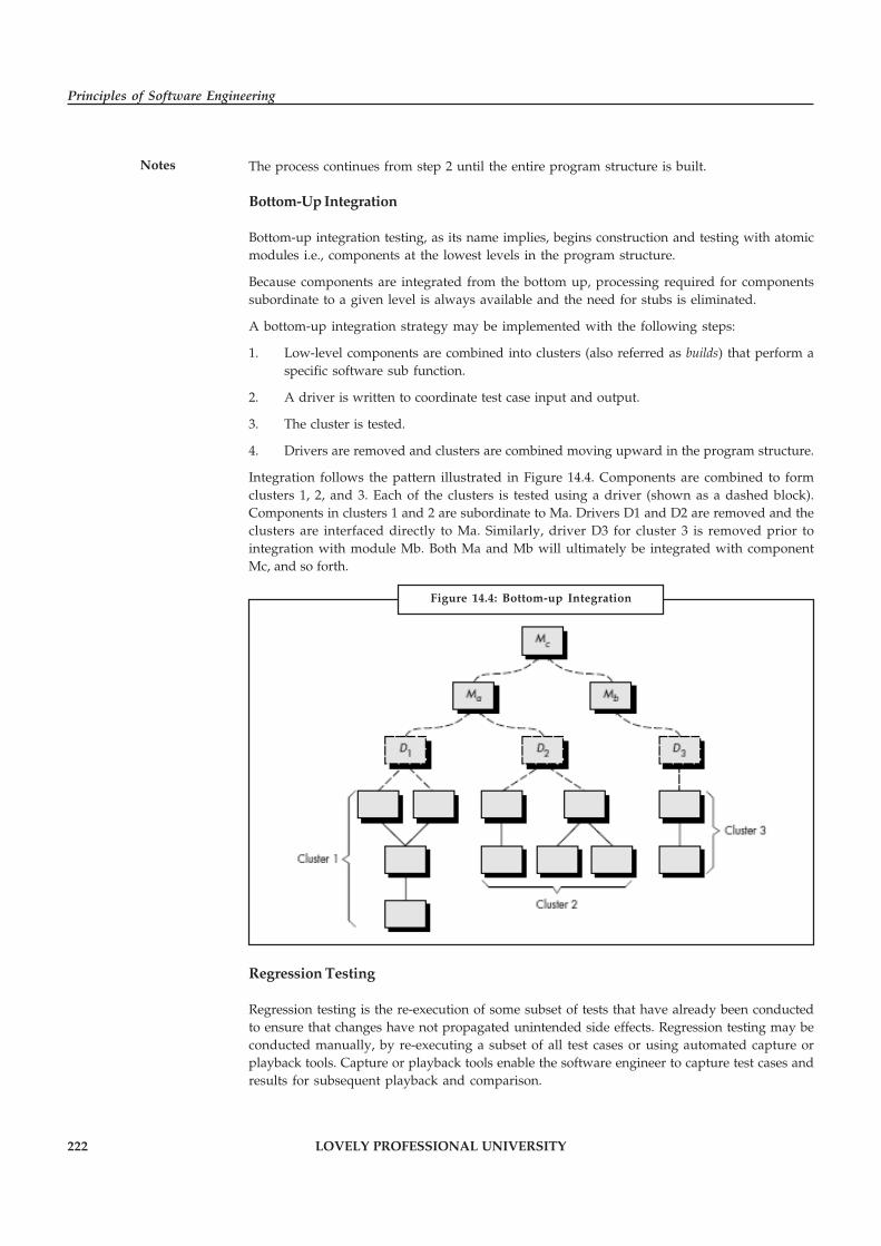
222 LOVELY PROFESSIONAL UNIVERSITY
Principles of Software Engineering
Notes The process continues from step 2 until the entire program structure is built.
Bottom-Up Integration
Bottom-up integration testing, as its name implies, begins construction and testing with atomicmodules i.e., components at the lowest levels in the program structure.
Because components are integrated from the bottom up, processing required for componentssubordinate to a given level is always available and the need for stubs is eliminated.
A bottom-up integration strategy may be implemented with the following steps:
1. Low-level components are combined into clusters (also referred as builds) that perform aspecific software sub function.
2. A driver is written to coordinate test case input and output.
3. The cluster is tested.
4. Drivers are removed and clusters are combined moving upward in the program structure.
Integration follows the pattern illustrated in Figure 14.4. Components are combined to formclusters 1, 2, and 3. Each of the clusters is tested using a driver (shown as a dashed block).Components in clusters 1 and 2 are subordinate to Ma. Drivers D1 and D2 are removed and theclusters are interfaced directly to Ma. Similarly, driver D3 for cluster 3 is removed prior tointegration with module Mb. Both Ma and Mb will ultimately be integrated with componentMc, and so forth.
Regression Testing
Regression testing is the re-execution of some subset of tests that have already been conductedto ensure that changes have not propagated unintended side effects. Regression testing may beconducted manually, by re-executing a subset of all test cases or using automated capture orplayback tools. Capture or playback tools enable the software engineer to capture test cases andresults for subsequent playback and comparison.
Figure 14.4: Bottom-up Integration
LOVELY PROFESSIONAL UNIVERSITY 223
Unit 14: Software Testing-II
NotesThe regression test suite (the subset of tests to be executed) contains three different classes of testcases:
� A representative sample of tests that will exercise all software functions.
� Additional tests that focus on software functions that are likely to be affected by thechange.
� Tests that focus on the software components that have been changed.
As integration testing proceeds, the number of regression tests can grow quite large. Therefore,the regression test suite should be designed to include only those tests that address one or moreclasses of errors in each of the major program functions. It is impractical and inefficient to re-execute every test for every program function once a change has occurred.
Smoke Testing
Smoke testing is an integration testing approach that is commonly used when “shrink-wrapped”software products are being developed. It is designed as a pacing mechanism for time-criticalprojects, allowing the software team to assess its project on a frequent basis. In essence, thesmoke testing approach encompasses the following activities:
1. Software components that have been translated into code are integrated into a “build.” Abuild includes all data files, libraries, reusable modules, and engineered components thatare required to implement one or more product functions.
2. A series of tests is designed to expose errors that will keep the build from properlyperforming its function. The intent should be to uncover “show stopper” errors that havethe highest likelihood of throwing the software project behind schedule.
3. The build is integrated with other builds and the entire product (in its current form) issmoke tested daily. The integration approach may be top down or bottom up.
The smoke test should exercise the entire system from end to end. It does not have to beexhaustive, but it should be capable of exposing major problems. The smoke test should bethorough enough that if the build passes, you can assume that it is stable enough to be testedmore thoroughly.
Smoke testing provides a number of benefits when it is applied on complex, time critical softwareengineering projects like it minimises the Integration risk, improves the quality of the end-product, error diagnosis and correction become simple and progress becomes easier to assessetc.
Task Make a difference between top-down and bottom-up integration.
14.1.3 System Testing
System testing is testing conducted on a complete, integrated system to evaluate the system’scompliance with its specified requirements. System testing falls within the scope of Black boxtesting, and as such, should require no knowledge of the inner design of the code.
System testing is actually done to the entire system against the Functional RequirementSpecifications (FRS) and/or the System Requirement Specification (SRS). Moreover, the Systemtesting is an investigatory testing phase, where the focus is to have almost a destructive attitudeand test not only the design, but also the behavior and even the believed expectations of the
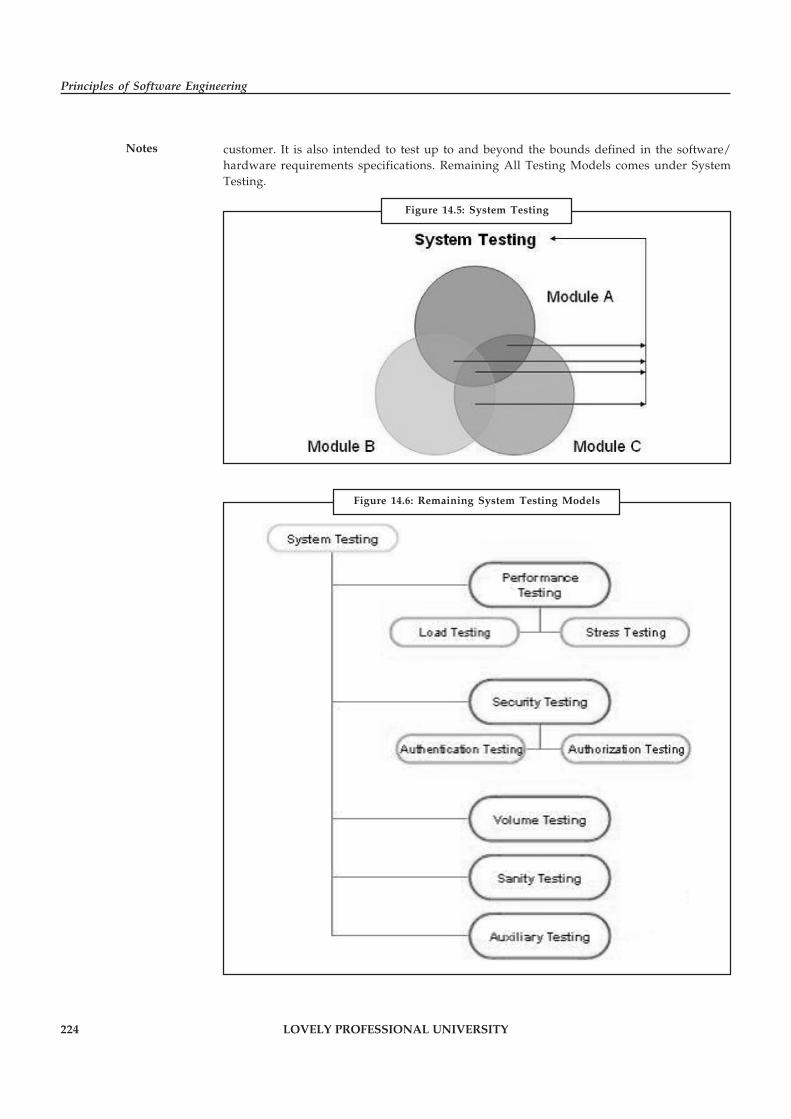
224 LOVELY PROFESSIONAL UNIVERSITY
Principles of Software Engineering
Notes customer. It is also intended to test up to and beyond the bounds defined in the software/hardware requirements specifications. Remaining All Testing Models comes under SystemTesting.
Figure 14.5: System Testing
Figure 14.6: Remaining System Testing Models

LOVELY PROFESSIONAL UNIVERSITY 225
Unit 14: Software Testing-II
Notes14.1.4 Acceptance Testing
This is arguably the most importance type of testing as it is conducted by the Quality AssuranceTeam who will gauge whether the application meets the intended specifications and satisfies theclient’s requirements. The QA team will have a set of pre written scenarios and Test Cases thatwill be used to test the application.
More ideas will be shared about the application and more tests can be performed on it to gaugeits accuracy and the reasons why the project was initiated. Acceptance tests are not only intendedto point out simple spelling mistakes, cosmetic errors or Interface gaps, but also to point out anybugs in the application that will result in system crashers or major errors in the application.
By performing acceptance tests on an application the testing team will deduce how the applicationwill perform in production. There are also legal and contractual requirements for acceptance ofthe system.
Self Assessment
Fill in the blanks:
1. …………………… focuses on verification of individual units or modules of software.
2. …………………… is a systematic technique for constructing the program structure whileat the same time conducting tests to uncover errors associated with interfacing.
3. …………………… testing is an incremental approach to construction of program structure.
4. …………………… testing, as its name implies, begins construction and testing with atomicmodules i.e., components at the lowest levels in the program structure.
5. …………………… is the re-execution of some subset of tests that have already beenconducted to ensure that changes have not propagated unintended side effects.
6. …………………… is an integration testing approach that is commonly used when “shrink-wrapped” software products are being developed.
7. …………………… is testing conducted on a complete, integrated system to evaluate thesystem’s compliance with its specified requirements.
14.2 Test Plan
In general, testing commences with a test plan and terminates with acceptance testing. A testplan is a general document for the entire project that defines the scope, approach to be taken, andthe schedule of testing as well as identifies the test items for the entire testing process and theperson responsible for the different activities of testing.
The test planning can be done well before the actual testing commences and can be done inparallel with the coding and design phases. The inputs for forming the test plan are: (1) projectplan (2) requirements document and (3) system design document. The project plan is needed tomake sure that the test plan is consistent with the overall plan for the project and the testing thetest plan is consistent with the overall plan for the project and the testing schedule matches thatof the project plan.
The requirements document and the design document are the basic documents used for selectingthe test units and deciding the approaches to be used during testing. A test plan should containthe following:
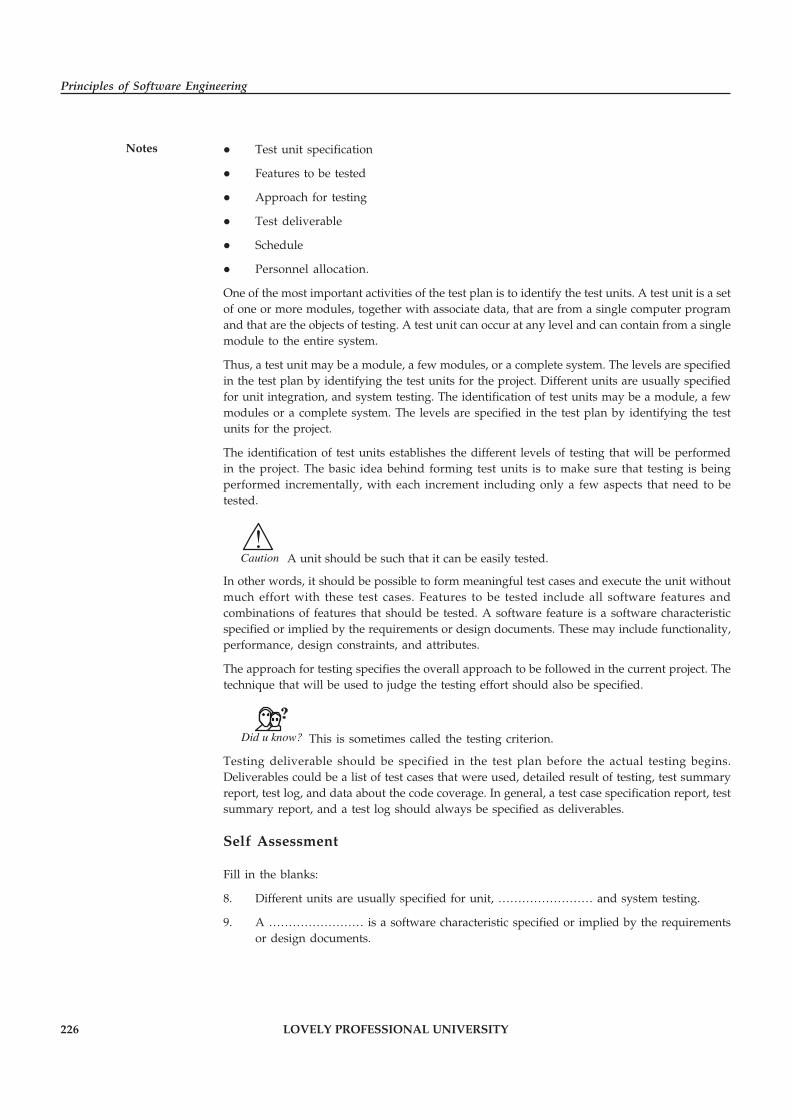
226 LOVELY PROFESSIONAL UNIVERSITY
Principles of Software Engineering
Notes � Test unit specification
� Features to be tested
� Approach for testing
� Test deliverable
� Schedule
� Personnel allocation.
One of the most important activities of the test plan is to identify the test units. A test unit is a setof one or more modules, together with associate data, that are from a single computer programand that are the objects of testing. A test unit can occur at any level and can contain from a singlemodule to the entire system.
Thus, a test unit may be a module, a few modules, or a complete system. The levels are specifiedin the test plan by identifying the test units for the project. Different units are usually specifiedfor unit integration, and system testing. The identification of test units may be a module, a fewmodules or a complete system. The levels are specified in the test plan by identifying the testunits for the project.
The identification of test units establishes the different levels of testing that will be performedin the project. The basic idea behind forming test units is to make sure that testing is beingperformed incrementally, with each increment including only a few aspects that need to betested.
!Caution A unit should be such that it can be easily tested.
In other words, it should be possible to form meaningful test cases and execute the unit withoutmuch effort with these test cases. Features to be tested include all software features andcombinations of features that should be tested. A software feature is a software characteristicspecified or implied by the requirements or design documents. These may include functionality,performance, design constraints, and attributes.
The approach for testing specifies the overall approach to be followed in the current project. Thetechnique that will be used to judge the testing effort should also be specified.
Did u know? This is sometimes called the testing criterion.
Testing deliverable should be specified in the test plan before the actual testing begins.Deliverables could be a list of test cases that were used, detailed result of testing, test summaryreport, test log, and data about the code coverage. In general, a test case specification report, testsummary report, and a test log should always be specified as deliverables.
Self Assessment
Fill in the blanks:
8. Different units are usually specified for unit, …………………… and system testing.
9. A …………………… is a software characteristic specified or implied by the requirementsor design documents.
LOVELY PROFESSIONAL UNIVERSITY 227
Unit 14: Software Testing-II
Notes14.3 Test Case Specifications
The test plan focuses on how the testing for the project will proceed, which units will be testedand what approaches (and tools) are to be used during the various stages of testing. However itdoes not deals with details of testing a unit nor does it specify which test case is to be used.
Test case specification has to be done separately for each unit. Based on the approach specified inthe test plan first the feature to be tested for this unit must be determined. The overall approachstated in the plan is refined into specific test techniques that should be followed and into thecriteria to be used for evaluation. Based on these the test cases are specified for testing unit.
The two basic reasons test cases are specified before they are used for testing. It is known thattesting has severe limitations and the effectiveness of testing depends very heavily on the exactnature of the test case. Even for a given criterion the exact nature of the test cases affects theeffectiveness of testing.
Constructing good test case that will reveal errors in programs is still a very creative activitythat depends a great deal on the tester. Clearly it is important to ensure that the set of test casesused is of high quality. As with many other verification methods evaluation of quality of testcase is done through “test case review” And for any review a formal document or work productis needed. This is the primary reason for having the test case specification in the form of adocument.
14.4 Execution and Analysis
Test execution involves running test cases developed for the system and reporting test results.The first step in test execution is generally to validate the infrastructure needed for running testsin the first place. This infrastructure primarily encompasses the test environment and testautomation, including stubs that might be needed to run individual components, synthetic dataused for testing or populating databases that the software needs to run, and other applicationsthat interact with the software. The issues being sought are those that will prevent the softwareunder test from being executed or else cause it to fail for reasons not related to faults in thesoftware itself. The members of the test team are responsible for test execution and reporting.
The test plan should be executed as designed according to the software objective. The test planshould be changed as per the progress, or notations made as to what aspects of the plan were notperformed. The test plan should commence when the project commences (Business Idea Phase)and conclude when the software is no longer in operation.
Important Steps of Software Test Plan Execution are:
1. Building the Test Environment
2. Creating the Test Plan
3. Design and prepare the Test Cases document
4. Executing the Test Cases taking the Test Plan guidelines.
Test analysis and design is the activity where general testing objectives are transformed intotangible test conditions and test designs.
Test analysis and design has the following major tasks:
� Review and analyse the requirements, architecture, design, interfaces and etc.
� Identifying Test Scenarios, test conditions, test requirements and also required test databased on analysis of test items, the specification, behavior and structure
228 LOVELY PROFESSIONAL UNIVERSITY
Principles of Software Engineering
Notes � Designing the test cases based on the Test Scenarios or Test Conditions
� Evaluating testability of the requirements and system
� Test environment setup and identifying any required infrastructure and tools
Self Assessment
State whether the following statements are true or false:
10. Test case specification has to be done separately for each unit.
11. For a given criterion the exact nature of the test cases affects the effectiveness of testing.
12. Test execution involves running test cases developed for the system and reporting testresults.
13. The test plan should be executed as designed according to the software objective.
14.5 Logging and Tracking
Schedule Tracking conduct periodic project status meetings in which each team member reportsprogress and problems. It evaluates the results of all reviews conducted throughout engineeringprocess. It determines whether formal project milestones have been accomplished by thescheduled date. It compare actual start – date to planned start date for each project date. It meetsinformally with practitioners to obtain their subjective assessment of progress to date andproblems on the horizon. It use earned value analysis to assess progress quantitatively.
Error Tracking allows comparison of current work to past projects and provides a quantitativeindication of the quality of the work being conducted. The more quantitative the approach toproject tracking and control, the more likely problems can be anticipated and dealt with in aproactive manner.
14.5.1 Earned Value Analysis
Earned value (EV) is one of the most sophisticated and accurate methods for measuring andcontrolling project schedules and budgets. Earned value has been used extensively in largeprojects, especially in government projects. PMI is a strong supporter of the earned value approachbecause of its ability to accurately monitor the schedule and cost variances for complex projects.
Although it is sophisticated, earned value can be scaled to be appropriate for any size of project.The key is in the project planning.
There are three primary advantages to using earned value:
� Accuracy in reporting
� Ability to deal with the uneven rate of project expenditures and work
� The early warning it provides project managers, allowing them to take the necessarycorrective action should the project be spending more money than it is physicallyaccomplishing
Other less professional methods for measuring budget and schedules generally only monitorthe percent of the time through the schedule and make the often mistaken assumption that thisis also the percent that the project should be through the budget. But cost and project progressgenerally are not evenly expended through a project. The reason earned value stands above thealternatives are that it accurately deals with this reality.
LOVELY PROFESSIONAL UNIVERSITY 229
Unit 14: Software Testing-II
NotesIt is one thing to meet a project deadline at any cost. It is another to do it for a reasonable cost.Project cost control is concerned with ensuring that projects stay within their budgets, whilegetting the work done on time and at the correct quality. One system for doing this, calledearned value analysis, was developed in the 1960s to allow the government to decide whether acontractor should receive a progress payment for work done. The method is finally coming intoits own outside government projects, and it is considered the correct way to monitor and controlalmost any project. The method is also called simply variance analysis.
Notes Variance analysis allows the project manager to determine trouble spots in theproject and to take corrective action.
The following definitions are useful in understanding the analysis:
� Cost Variance: Compares deviations and performed work.
� Schedule Variance: Compares planned and actual work completed.
� BCWS (Budgeted Cost of Work Scheduled): The budgeted cost of work scheduled to bedone in a given time period, or the level of effort that is supposed to be performed in thatperiod.
� BCWP (Budgeted Cost of Work Performed): The budgeted cost of work actually performedin a given period, or the budgeted level of effort actually expended. BCWP is also calledearned value and is a measure of the dollar value of the work actually accomplished in theperiod being monitored.
� ACWP (Actual Cost of Work Performed): The amount of money (or effort) actually spentin completing work in a given period.
Variance thresholds can be established that define the level at which reports must be sent tovarious levels of management within an organization.
Cost Variance = BCWP – ACWP
Schedule Variance = BCWP – BCWS
Variance: Any deviation from plan by combining cost and schedule variances, an integratedcost/schedule reporting system can be developed.
Self Assessment
Fill in the blanks:
14. …………………… evaluates the results of all reviews conducted throughout engineeringprocess.
15. …………………… allows comparison of current works to past projects and provides aquantitative indication of the quality of the work being conducted.
14.6 Metrics
Metric is a standard unit of measurement that quantifies results. Metric used for evaluating thesoftware processes, products and services is termed as Software Metrics. Software Metrics is aMeasurement Based Technique which is applied to processes, products and services to supplyengineering and management information and working on the information supplied to improveprocesses, products and services, if required.

230 LOVELY PROFESSIONAL UNIVERSITY
Principles of Software Engineering
Notes Increase in competition and leaps in technology have forced companies to adopt innovativeapproaches to assess themselves with respect to processes, products and services. This assessmenthelps them to improve their business so that they succeed and make more profits and acquirehigher percentage of market. Metric is the cornerstone in assessment and also foundation forany business improvement.
Let us discuss the importance of metrics.
� Metrics is used to improve the quality and productivity of products and services thusachieving Customer Satisfaction.
� Easy for management to digest one number and drill down, if required.
� Different Metric(s) trend act as monitor when the process is going out of control.
� Metrics provides improvement for current process.
Limitations of metrics are:
� Many company avoid metrics because its time consuming and expensive.
� Metrics has to be prepared with full understanding about the concepts of metrics anddetails of projects. Metrics has direct impact on the project as it tells the user about theprogress in project.
� It’s very difficult to maintain and keep track of the metrics.
Good practices to follow:
� Metrics are essential to maintain the high quality of the project.
� Metrics tell the progress of the project, so it helps to maintain the standards.
� To maintain the metrics, it’s very important to have a good communication between theteams to get the details about the project.
� Metrics helps the team to work in right path.
� Metrics helps to maintain the high quality of the project and also cost effective.
� Metrics gives a complete understanding about the project and also help to make rightdecision in every phase.
14.6.1 Failure Data Estimation
Software reliability refers to the probability of failure-free operation of a system. It is related tomany aspects of software, including the testing process. Directly estimating software reliabilityby quantifying its related factors can be difficult. Testing is an effective sampling method tomeasure software reliability. Guided by the operational profile, software testing (usually black-box testing) can be used to obtain failure data, and an estimation model can be further used toanalyze the data to estimate the present reliability and predict future reliability. Therefore,based on the estimation, the developers can decide whether to release the software, and theusers can decide whether to adopt and use the software. Risk of using software can also beassessed based on reliability information.
Notes The primary goal of testing should be to measure the dependability of testedsoftware.
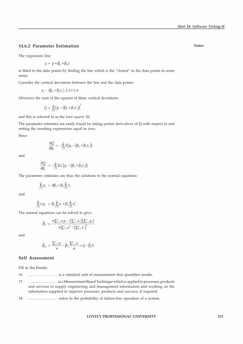
LOVELY PROFESSIONAL UNIVERSITY 231
Unit 14: Software Testing-II
Notes14.6.2 Parameter Estimation
The regression line:
y = 0 1y x= β +β
is fitted to the data points by finding the line which is the “closest” to the data points in somesense.
Consider the vertical deviations between the line and the data points:
yi – ( )0 1 ,1ix i nβ + β ≤ ≤
Minimizes the sum of the squares of these vertical deviations:
Q = ( )( )2
0 11
n
i ii
y x=
− β + β∑
and this is referred to as the least squares fit.
The parameter estimates are easily found by taking partial derivatives of Q with respect to andsetting the resulting expressions equal to zero.
Since
0
Q∂∂β
= ( )( )0 112
n
i ii
y x=
− − β +β∑
and
1
Q∂∂β
= ( )( )0 112
n
i i ii
x y x=
− − β +β∑
The parameter estimates are thus the solutions to the normal equations:
1
n
ii
y=
∑ = 0 11
n
ii
n x=
β +β ∑
and
1
n
i ii
x y=
∑ = 20 1
1 1.
n n
i ii i
x x= =
β + β∑ ∑
The normal equations can be solved to give:
1β̂ = ( )( )
( )1 1 1
221 1
n n ni i ii i i i
n ni ii i
n x y x y
n x x
= = =
= =
−∑ ∑ ∑
−∑ ∑
and
0β̂ = 1 11 1
ˆ ˆ .n ni ii iy x
y xn n= =
∑ ∑−β = − β
Self Assessment
Fill in the blanks:
16. …………………… is a standard unit of measurement that quantifies results.
17. …………………… is a Measurement Based Technique which is applied to processes, productsand services to supply engineering and management information and working on theinformation supplied to improve processes, products and services, if required.
18. …………………… refers to the probability of failure-free operation of a system.

232 LOVELY PROFESSIONAL UNIVERSITY
Principles of Software Engineering
Notes 14.7 Summary
� The first level of testing is called unit testing. Unit testing focuses on verification ofindividual units or modules of software.
� The next level of testing is often called integration testing. Integration testing is a systematictechnique for constructing the program structure while at the same time conducting teststo uncover errors associated with interfacing.
� System testing is testing conducted on a complete, integrated system to evaluate thesystem’s compliance with its specified requirements.
� The test planning can be done well before the actual testing commences and can be donein parallel with the coding and design phases.
� The test plan focuses on how the testing for the project will proceed, which units will betested and what approaches (and tools) are to be used during the various stages of testing.
� Test execution involves running test cases developed for the system and reporting testresults.
� Schedule Tracking conduct periodic project status meetings in which each team memberreports progress and problems. It evaluates the results of all reviews conducted throughoutengineering process.
� Metric is a standard unit of measurement that quantifies results. Metric used for evaluatingthe software processes, products and services is termed as Software Metrics.
14.8 Keywords
Bottom-up Integration: Bottom-up integration testing begins construction and testing withatomic modules i.e., components at the lowest levels in the program structure.
Earned Value (EV): Earned value (EV) is one of the most sophisticated and accurate methods formeasuring and controlling project schedules and budgets.
Integration Testing: Integration testing is a systematic technique for constructing the programstructure while at the same time conducting tests to uncover errors associated with interfacing.
Metric: Metric is a standard unit of measurement that quantifies results.
Regression Testing: Regression testing is the re-execution of some subset of tests that havealready been conducted to ensure that changes have not propagated unintended side effects.
Smoke Testing: Smoke testing is an integration testing approach that is commonly used when“shrink-wrapped” software products are being developed.
Software Reliability: Software reliability refers to the probability of failure-free operation of asystem.
System Testing: System testing is testing conducted on a complete, integrated system to evaluatethe system’s compliance with its specified requirements.
Top-down Integration: Top-down integration testing is an incremental approach to constructionof program structure.
Unit Testing: Unit testing focuses on verification of individual units or modules of software.
Variance: Any deviation from plan by combining cost and schedule variances, an integratedcost/schedule reporting system can be developed.
LOVELY PROFESSIONAL UNIVERSITY 233
Unit 14: Software Testing-II
Notes14.9 Review Questions
1. What is unit testing? What are the advantages of unit testing?
2. Explain the scaffolding required testing a program unit.
3. Define integration testing. Explain top-down and bottom-up integration.
4. “Capture or playback tools enable the software engineer to capture test cases and resultsfor subsequent playback and comparison”. Elucidate.
5. Write down the three different classes of test cases of regression test suite.
6. What is smoke testing?
7. Discuss about system testing.
8. “Testing commences with a test plan and terminates with acceptance testing”. Comment.
9. Briefly explain about test case specifications.
10. Provide insight into logging and tracking.
11. “Metric is a standard unit of measurement that quantifies results”. Explain. Also discussthe failure data estimation.
Answers: Self Assessment
1. Unit testing 2. Integration testing
3. Top-down integration 4. Bottom-up integration
5. Regression testing 6. Smoke testing
7. System testing 8. Integration
9. Software feature 10. True
11. True 12. True
13. True 14. Schedule Tracking
15. Error Tracking 16. Metric
17. Software Metrics 18. Software reliability
14.10 Further Readings
Books Rajib Mall, Fundamentals of Software Engineering, 2nd Edition, PHI.
Richard Fairpy, Software Engineering Concepts, Tata McGraw Hill, 1997.
R.S. Pressman, Software Engineering – A Practitioner’s Approach, 5th Edition, TataMcGraw Hill Higher education.
Sommerville, Software Engineering, 6th Edition, Pearson Education.
Online links rajeevprabhakaran.wordpress.com/2008/11/20/levels-of-testing/

234 LOVELY PROFESSIONAL UNIVERSITY
Principles of Software Engineering
Notes http://www.tutorialspoint.com/software_testing/levels_of_testing.htm
www.cs.swan.ac.uk/.../20061202_Oladimeji_Levels_of_Testing.pdf
ecomputernotes.com/software.../discuss-the-different-levels-of-testing

Jalandhar-Delhi G.T. Road (NH-1)Phagwara, Punjab (India)-144411For Enquiry: +91-1824-300360Fax.: +91-1824-506111Email: [email protected]
LOVELY PROFESSIONAL UNIVERSITY