principles of musculoskeletal ultrasound curtiss 2013.pdf · principles of musculoskeletal...
TRANSCRIPT

Principles of Musculoskeletal
Ultrasound
Heather Curtiss, M.D.
University of Utah
PM&R Sports Medicine Fellow
January 30, 2013

Disclosures
None
Outline
IntroductionBenefits and Limitations of USUltrasound (US) PhysicsTerminologyEquipmentNormal US appearance of
structuresArtifacts Injection techniqueConclusions

Introduction
Physiatrists involved in US ~ 6 decades
Founded American Institute for Ultrasound in Medicine (AIUM) in 1951
Initially: therapeutic US
High frequency, real-time MSK US imaging – 1980’s
Now used by many physiatrists
Diagnostic
Interventional

Introduction
Definition :
Use of high frequency sound waves (3-17 MHz) to image soft tissues and bony structures in the body for the purposes of diagnosing pathology or guiding interventional procedures
Detailed images of MSK system
Sub-millimeter images
Higher resolution than MRI for superficial structures

Introduction - Indications Interventional Injections Tenotomy Aspiration/lavage Biopsy
Diagnostic Tendon (tendinopathy, tears) Muscle (strains, contusions) Nerve (entrapment) Ligament (sprains) Joint (effusions) Dynamic

Benefits of MSK US Ability to image in real-time
= hands-on, dynamic, fast
Interactive – allows feedback from patient
Generally unaffected by metal artifacts
No radiation to patient or provider
Exam of contralateral limb for comparison
High resolution
Real-time guidance for interventional procedures
Portable
Relatively inexpensive

Limitations of MSK US
Limited field of view Detailed picture of relatively small area
Limited penetration Lower resolution at greater depths Unable to penetrate bone
Operator dependent Education (anatomy), scanning skills and
interpretation
Lack of current individual certification
Equipment – cost, quality variable

Ultrasound Physics Transducer (probe)
Contains linear array of thin
crystals (lead zirconate titanate) linked
to the electrical system of the machine
Machine
Applies a rapidly alternating
electrical current to the crystals
vibration generate sinusoidal
sound wave (mechanical energy) =
Piezoelectricity

Ultrasound Physics
The frequency and amplitude of the sound waves are determined by:
electrical current used to stimulate the crystals
material properties of the crystals
thickness of the crystals
A range of frequencies are produced (Bandwidth)
There is a preferential frequency
Higher frequency higher resolution but increased scatter (reduced penetration)

Ultrasound Physics Emission (requires a medium) Forward transmission until acoustic interface
(change in the density of adjacent tissues): Recognizes differences
Partial Reflection Back to the transducer (now a receiver) Sound
energy transformed into electrical signal)
Processing Computer calculates amplitude , depth and time
of return signal and generates 2-D black/white B-mode image of the body

Ultrasound Physics
Echoes
Perpendicular incidence
Reflected pulse -
reflected directly back
Transmitted pulse –
passes straight through
Oblique incidence
Some reflected back
at an angle
Some passes through
refracted (transmission
angle)

Reflection
o Scattering
o Redirection of sound in several
directions due to rough edges
(torn tissue) or heterogeneous
media
o Some of the sound is reflected
back to the transducer (=
backscatter)
visualization of the media
o Specular Reflection
o Reflection from a smooth surface

Ultrasound Physics
Attenuation
Weakening of sound amplitude and intensity as
the wave propagates through a medium
Absorption, Reflection, Scattering
Attenuation coefficient
Reduction (in dB) per centimeter (cm) traveled
Dependent on the tissue
Soft tissue attenuation / cm = 0.5 x freq (MHz)
Higher frequency More attenuation

Ultrasound Physics
Impedance (Acoustic interface) US waves are reflected at the interface of two different
tissues, dependent on the properties of each tissue
Echogenicity = Ability to reflect sound waves back to transducer
If reflects large amount of sound brighter Interface composed of very different tissues e.g. interface between bone and muscle (bone = bright)
Less reflection darker More similar tissues
Important point Images are based on the relative material properties of
the tissue compared with adjacent regions
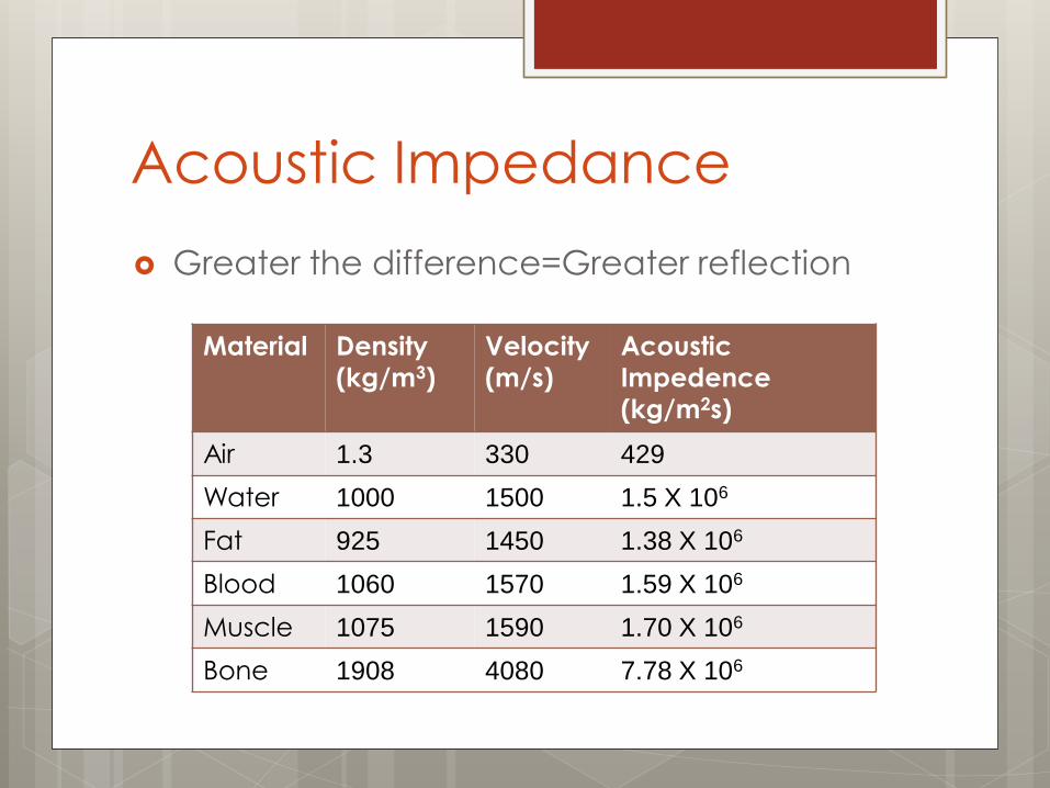
Acoustic Impedance
Greater the difference=Greater reflection
Material Density
(kg/m3)
Velocity
(m/s)
Acoustic
Impedence
(kg/m2s)
Air 1.3 330 429
Water 1000 1500 1.5 X 10⁶
Fat 925 1450 1.38 X 10⁶
Blood 1060 1570 1.59 X 10⁶
Muscle 1075 1590 1.70 X 10⁶
Bone 1908 4080 7.78 X 10⁶

Ultrasound Use
Step 1
Transducer selection
Step 2
Depth
Step 3
Focal zone
Step 4
Adding focal zones
Step 5
Gain
Step 6
Time gain
compensation

Step 1: Transducers
Frequency
Expressed in megahertz (MHz)
High frequency
Greater resolution, shallow penetration
(attenuation)
Best for more superficial structures
Low frequency
Lower resolution, greater penetration
For deeper structures

Transducers
Linear array
End of transducer
flat
Sound waves exit
perpendicular
Less anisotropy
Limited field of view
Good for superficial
structures
Curvilinear array
End of transducer
curved
Sound waves
emitted in a fan
Increased anisotropy
Large field of view
Good for deep
structures

Transducer positioning
Simultaneous contact with:
Transducer
Skin surface,
Examiner’s hand
Maintains proper
pressure of transducer
on the skin
Avoids involuntary
movement of the
transducer
Allows fine adjustments
in transducer positioning
“Full contact sport” –Jay Smith, MD

Transducer Positioning
Longitudinal
Parallel to long
axis of the structure
Transverse
Perpendicular to the long axis of the structure

Transducer Handling
Heel-Toe
Wagging
Rotation

Step 2: Depth Adjust depth to
place image at middle to bottom of screen
Decreases attenuation, increases resolution
Scale allows localization

Step 3: Focal Zone
Beam narrows to ½ width and then widens Narrowest region of
beam has most concentrated sound waves best resolution
Set Focal Zone to location of interest

Step 4: Adding Focal Zones
Can add zones if
multiple areas or
broad area of
interest
Multiple focal
zones reduce
temporal resolution
Cost/Benefit

Step 5: Gain
Overall Brightness
of image
Auto gain on some
machines
Optimize for
structure of interest

Step 6: Time Gain
Compensation
Gain at certain depths
Sliding switches on machine
Automatic on some machines
Adjusts brightness at a certain depth to
control for attenuation

Image Identification

Terminology - Echotexture
Refers to the internal pattern of echoes
Coarseness
Homogeneity and heterogeneity

Terminology - Echogenicity Hyperechoic
More sound waves reflected
Isoechoic Same amount of sound waves
reflected
Hypoechoic Fewer sound waves reflected
Anechoic No sound waves reflected
Difference is more important Consider surrounding tissues

Normal US Characteristics

Normal Appearance - Muscle
Longitudinal
“Feather or veins
on a leaf pattern”
Transverse
“Starry night
pattern”

Normal Appearance - Tendon
Longitudinal
“Fibrillar appearance”
Transverse
“Broom end pattern”
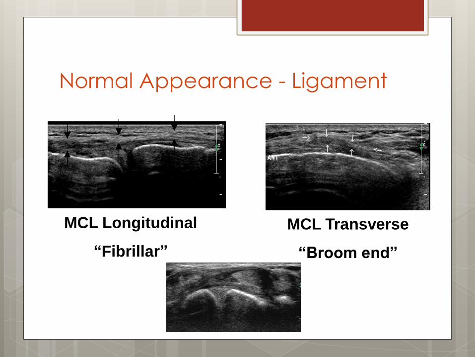
Normal Appearance - Ligament
MCL Longitudinal
“Fibrillar”
MCL Transverse
“Broom end”

Normal Appearance - Bone
Cortex=bright
Hyperechoic
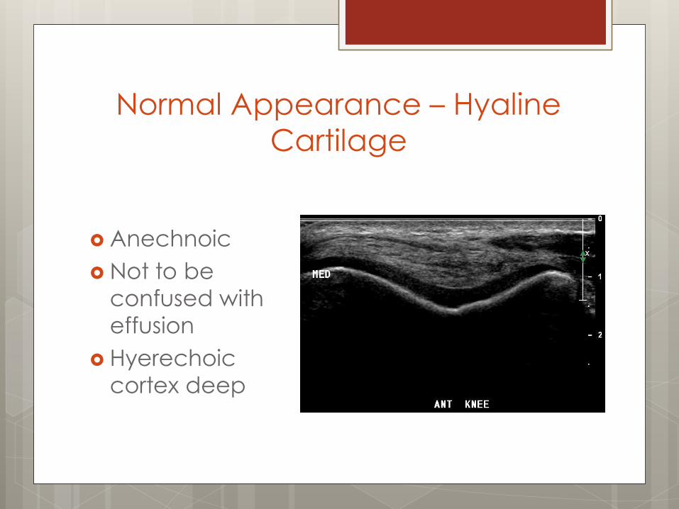
Normal Appearance – Hyaline
Cartilage
Anechnoic
Not to be
confused with
effusion
Hyerechoic
cortex deep

Normal Appearance - Nerve
Transverse –
“Honeycomb pattern”
Longitudinal
“Fascicular”

Normal Appearance –
Vasculature
Longitudinal -
CPA
Transverse -
CPA
Transverse

Extended Field of View
Panoramic/Extended Field of View
Transducer is glided parallel to the scan plane along the structure of interest
New echoes added to original image
Allows production of pictures wider than the transducer face

Artifacts - Anisotropy Anisotropy US beam not parallel to structure Structure appears dark or pathologic due
to reflection Avoided by manipulating the transducer to
direct the US beam perpendicular to the structure (tilting, heel-toe)
Always look for pathology in multiple planes

Artifacts - Anisotropy

Artifacts – Posterior reverberation
Smooth and flat
objects
Metal
Bone
Needle
Reflects back
and forth
Series of echoes

Artifacts – Posterior Acoustic
Shadowing
Anechoic
below bone or
calcification
i.e. calcific
tendinitis

Artifacts – Posterior acoustic
enhancement (increased through-
transmission)
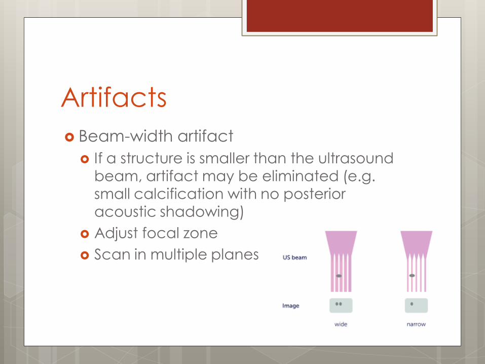
Artifacts
Beam-width artifact
If a structure is smaller than the ultrasound beam, artifact may be eliminated (e.g. small calcification with no posterior acoustic shadowing)
Adjust focal zone
Scan in multiple planes

Injection Considerations
Approach
Room Arrangement
Image location
Needle approach
Sterile technique
Needle visualization techniques

Injection Approach
In plane, Longitudinal Out of plane, Transverse
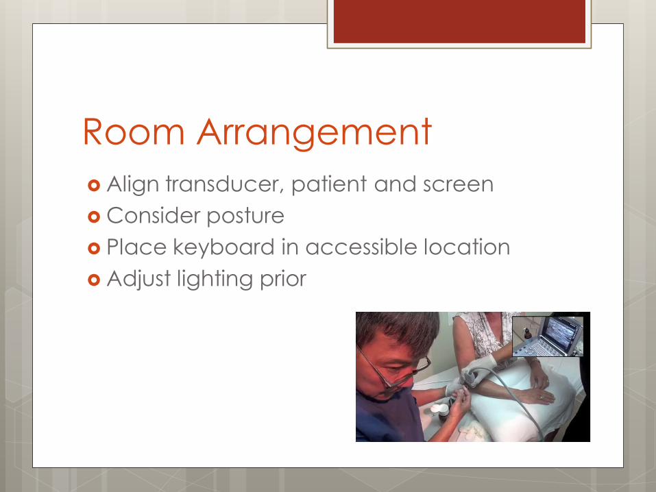
Room Arrangement
Align transducer, patient and screen
Consider posture
Place keyboard in accessible location
Adjust lighting prior

Image location
Pre-examine approach
Use Doppler prior
Place image closer to needle insertion

Needle approach
Check depth and insert appropriately
Keep needle parallel to transducer
Use in-plane approach if possible

Sterile technique
Sterile Gel
Probe cover
Draping as needed
Can be sterile work space if extended procedure

Needle visualization Smaller gauge=more
difficult
Parallel to transducer
Hydrodissection
Small injection for needle contrast
Jiggling
Back-and-forth needle motion without advancement
Conclusions Ultrasound has many uses for physiatrists. There are many benefits and limitations of US. Basic understanding of US physics is important
for image optimization. Various tissues can be identified due to their
anatomic location, echotexture, and echogenicity.
Always optimize your image first. Recognize common artifacts. Only use proper injection technique or defer
the procedure.