principles of microscope illumination and the problem of glare
TRANSCRIPT

Journal of the
OPTICALOf
SOCIETYAMERICA
VOLUME 34, NUMBER 12 DECEMBER, 1944
Principles of Microscope Illumination and the Problem of Glare
WILFRID TAYLOR DEMPSTER
Department of Anatomy, University of Michigan, Ann Arbor, Michigan
(Received September 20, 1944)
The manipulations in using the microscope, other thanthe selection of lenses, focusing, and placement of slides,relate to the illumination. When the illumination is nothandled with judgment, glare and lack of contrast result,and crisp images are not obtained. Effective illuminationsdepend equally upon three factors, the condenser, the fieldstop, and the illuminant proper. The adjustments forsuperior glare-free illumination are discussed and the term"controlled" illumination is suggested as an appropriatedesignation for such illumination. Aspects of the lightingrequirements of the microscope are analyzed, and it isshown that suitable regulation of the apertures of the fieldand condenser stops are the basic requirements for con-trolled illumination. Various types of lighting may be usedin conjunction with these adjustments. The paper is pre-
sented against a background of the pertinent historicaldevelopments and the various factors relating to illumina-tion are reviewed in a broader fashion than is common intexts on microscopy. Explanations of the principles and thedefects of illumination are presented with the generalbiological user of the microscope in mind. The shapes andproportions of the various illuminating beams that play onspecimens are illustrated. Aberrations and the origin ofglare are explained. In general, there are two extremes inthe practical use of illumination-illumination for highresolution and illumination for maximum contrast. Themicroscopist should ordinarily vary his illumination as heworks to obtain the advantages of each type of illumination.The conditions of each are fully treated.
T HOUGH the basic principles of microscopeT illumination, and effective systems of illu-mination too, were developed a half-century ago,it is apparent that these principles have not beensufficiently well understood to guide currentpractice in microscopy. Most microscope usershave consistently ignored the better methods ofillumination and have tolerated discomfort, in-adequate illumination, and work that does notreflect the capacity of a precision instrument.Recent texts' on microscopy and photomi-
1 John Belling, The Use of the Microscope (McGraw-HillBook Company, Inc., New York, 1930). S. H. Gage,The Microscope (Comstock Publishing Company, Ithaca,New York, 1932). Conrad Beck, The Microscope, Theoryand Practice (R. and J. Beck, London, 1938). F. J. Mufiozand H. A. Charipper, The Microscope and Its Use (ChemicalPublishing Company, Brooklyn, New York, 1943). J. E.Barnard andl F. V. Wclch, Practical Photonmicrography
crography have uniformly emphasized the im-portance of illumination, and the half-century oldtechniques have been presented anew as adjunctsimportant to successful work with the micro-scope. Even so, the practical worker has not yetbeen provided with a historical perspective norwith a basis for a clear understanding of effectivemicroscope illumination. The treatment below isan essay in this direction.2
(E. Arnold and Company, London, 1936). G. G. Reinert,Praktische Mikrofotografie (W. Knapp, Halle, 1937). R.M. Allen, Photomicrography (D. Van Nostrand Company,New York, 1941). C. P. Shillaber, Photomicrography inTheory and Practice (John Wiley & Sons, Inc., New York,1944).
2 I am greatly indebted to Dr. 0. W. Richards, SpencerLens Company, and Dr. G. L. Walls, Bausch and LombOptical Company, for their critical comments on a pre-liminary draft of the manuscript.
695

WILFRID TAYLOR DEMPSTER
A variety of illuminating devices for micros-copy with transmitted light has been introducedsince the early days of the nineteenth century.3The modern illuminating apparatus, however,stems from the condenser of Abbe. When thisdevice was introduced,4 Abbe stated that forgeneral microscopical work, if one focused theimage of a cloud (or of an artificial light sourcebehind a globe-like flask of water, preferablytinted blue) upon an object in the field of view,suitable illumination was provided. Although theconcept of focused illumination antedates Abbeby many years, most of the early advocates offocused illumination compromised and thus didnot employ it in practice.'
For a decade after the introduction of the Abbecondenser, during which period the correctedsubstage condenser also appeared,6 the devicegradually came into scientific use. The rise ofbacteriology and of the more advanced micro-scopical anatomy of the time facilitated theacceptance of the condenser as an integral partof the microscope. The condenser, however, wasa complication and how it was to be used becamea problem. Abbe's experiments leading to atheory of microscope image formation' werebased on the use of narrow illuminating beams(i.e., constricted condenser stop) and, often, ofobliquely directed narrow beams. "According totheory, wide cones are not as good as narrow."8
A number of practical workers followed Abbe inthe use of narrow cone illumination.9 In the handsof the majority of workers, however, the con-denser became merely a device for modifying theintensity of illumination. This was done by
3 Hugo von Mohl, Mlikrographie, oder Anleitung zurKenntniss und zzo Gebraucle des J11ikroskops (L. F. Fues,Tubingen, 1846). E. M. Nelson, J. Roy. MIicroscop. Soc. 7,90-105 (1891).
4 E. Abbe, Arch. f. mikroskop. Anat. 9, 469-480 (1873).Reprinted in Gesannnelte Abandlungen von Ernst Abbe(G. Fischer, Jena, 1904), Vol. 1, and condensed translationin E. Abbe, Monthly Microscop. J. 13, 77-82 (1875).
6Nelson, reference 3. Focused illumination is but one ofthe possible techniques for securing effective illumination;it lends itself well to control. Control is the sine qua non ofgood illumination and, as will be shown, control is possibleonly when the plane of condenser focus is adjusted sothat its falls at or near the level of objects (on a slide) inthe field of view.
6 Note in J. Roy. Microscop. Soc., p. 609 (1889).7 E. Abbe, Arch. f. mikroskop. Anat. 9, 413-468 (1873).
Also in Gesamelte Abhandlungen von Ernst Abbe, Vol. 1,pp. 45-100.
8 E. Abbe, J. Roy. Microscop. Soc., pp. 721-724 (1889).9 The distinction between wide and narrow cones is
shown in Fig. 6.
opening or constricting the condenser iris or byaltering the condenser focus through raising orlowering the condenser level. Similar misuse ofthe condenser is common today."
Nelson, during the 1880's and later, repeatedlydemonstrated" that if wide-angled illuminatingcones from the condenser, associated with a widecondenser aperture, were focused on an object,finer details of structure could be seen than whennarrow beams were employed. He showed thatthe highest degree of resolution that is possiblefor a given objective and a given wave-length oflight is obtained only when the cone of condenserillumination is exactly as wide-angled as thewidest cone that may enter the objective. Withsuch illumination, according to the analyticaltreatment of Rayleigh, 2 an object acts as if itwere self-luminous, 'and it is a self-luminous ob-ject that allows the highest resolution possible fora given objective. Resolution, in fact, is justtwice as great as that obtained by a parallel beamand an object which acts like a grating. Inter-mediate degrees of resolution are obtained whenthe condenser stop is constricted to permit lessthan full cone illumination. It is ordinarilystated 3 that resolution is proportional to one-halfof the N.A.' 4 value of the objective plus one-half the working (N.A.) aperture of the condenser.
Published photographs illustrating the effect ofvarious condenser apertures on the resolution ofan objective seem to deal only with transparentor refractile objects like diatoms ;15 gratings, too,have been common as test objects. Figure 1
1l It should be stated emphatically at the outset thatillumination intensity is a most important variable inmicroscopy; and where serious microscopy is attempted,a rheostat, neutral wedges, or filters should be employedto regulate intensity. The condenser is not for this purpose.
"1 E. M. Nelson, Eng. Mech. 40, 68, 157-158, 263, 282(1 884). E. M. Nelson, J. Roy. Microscop. Soc., pp. 282-289(1910). Nelson, reference 3.
"Lord Rayleigh, Phil. Mag. 42, [5], 167-195 (1896).13 L. C. Martin, An Introduction to Applied Optics (Isaac
Pitman and Sons, London, Vol. 1, 1930; Vol. 2, 1932).14 N.A. is a numerical designation of the wideness of
cone angle for the largest light cone that may be trans-mitted by a given objective. Similarly, it refers to theproportions of a beam emerging from a condenser and iscorrelated with the size of the condenser stop. N.A.= (thesine of the half-angle-in air--of the marginal rays of thelight cone) X (the refractive index of the medium intowhich the cone is projected). Cf. Fig. 6, E. The lowerangle of the triangle is the half-angle of the light cone.
"For instance, in: C. R. Marshall and H. D. Griffith,An Introduction to the Theory and Use of the Microscope(G. Routledge and Sons, London, 1928), and Beck,reference 1. Shillaber, reference 1 shows photographs ofstarch grains with different illumination.
696

PRINCIPLES OF MICROSCOPE ILLUMINATION
FIG. 1. A-G: Several cells of monkey parathyroid gland stained for mitochondrial granules in the ctoplasm; 3 sectionX 1500. A-D shows the appearance with oil-immersion (A); and with 4-mm (B), 8-mm (C), and 16-mm (D) objectives,each with full cone illumination. The numerator and denominator represent, respectively, the N.A. of the objective andthat of the condenser. E-G are oil-immersion figures but with reduced condenser apertures as indicated. H shows twoglobules of mercury photographed with reduced and with full cone illumination; the former illumination results indiffraction bands, X 1500.
shows a more common type of biological specimen(a stained preparation) photographed with differ-ent objectives, each one with full cone illumi-nation (A-D), and also photographed (E-G) withone high power objective but with the condenserstopped more or less. The illustrations (E-G)show that smaller condenser stops result in in-creased depth of focus, heightened contrast, anddecreased glare. A decrease in resolution also maybe seen, and its extent may be compared with thelowered resolution (B-D) caused by objectives oflower aperture.
STANDARD METHODS OF LIGHTING
Nelson's method, which was particularly suitedto high power work, was named "critical illumi-nation." He placed an incandescent gas flame atsome arbitrary distance from the microscope andadjusted it so that the flame could be viewed edgeon. The essential features of Nelson's methodwere two: (1) the exact imaging of a luminoussource in the field of view by raising or loweringthe condenser level, and (2) the use of full cone,or nearly full cone, illumination. Exact focusingof a luminous source calls for a perfectly homo-geneous luminous source, such as an incandescentflame, and since it is difficult to obtain large sizesources that are equally luminous throughout,
the method has been largely limited to the higherpower types of microscopy. The flame, substagemirror, condenser, and microscope were alignedoptically. An object was brought into focus in thefield of view and, by raising or lowering the con-denser, the flame was also accurately imaged inthe field of view. Then the condenser iris wasadjusted till the condenser aperture coincidedwith that of the objective (i.e., full cone illumi-nation). This was done by removing the ocularand opening or closing the condenser iris till theuppermost lens of the objective, as seen throughthe open microscope tube, was flooded with lightnearly to its margin.1 6
Because the filament of the electric lamp doesnot provide a suitably broad incandescent area, afilament electric lamp is a poor source for focusedillumination. Ground glass or opalescent screens(Fig. 2, B) are grainy; they decrease the intensityof light noticeably; and, since diffusion is im-
perfect, the bright image of the filament showsthrough and produces a bright central spot anda non-homogeneous field. As a means of im-proving filament (and arc) sources, glass speculae(glass rods, perhaps a half-inch in diameter and
16 The general method of examining the luminous appear-ance of an objective through the open draw tube (or bymeans of a suitable lens, through the ocular) was describedby Abbe, reference 7.
697

WILFRID TAYLOR DEMPSTER
several inches long) have been devised, 7 so thatthe light could be diffused by total internal re-flection on the walls of the rod (Fig. 2, C). Forhigh intensity illumination, light may be concen-trated into a speculum by a lens or the speculumitself may be made with a trumpet shape. 8 Thespeculum, like the flame, though highly satis-factory for high power and immersion work, is asmall-sized source and thus is useless for lowpower observation.
Light reflected from a suitable large whitematte reflecting surface might be adequate forlow power work, but such a system would gener-ally be of low efficiency. An effective homogene-ous illumination, however, is provided if lightsources are enclosed as in a stereoptican projectoror (integrating sphere) episcope (Fig. 2, D)having a white interior. A convex lens may ormay not be used at the window of the episcope.
Auxiliary lenses and bull's eyes had been em-ployed in microscopy since the seventeenthcentury and the condenser itself is nothing but arefined lens system for concentrating light. It isnatural then that auxiliary lenses should havebeen tried in conjunction with the condenser toincrease illumination intensity and the apparentsize of a luminous source. When a fairly largecollecting lens is aligned in front of a source ofsmall area and at a suitable distance, an image ofthe source is projected through collecting lensand condenser to a focus at object level (Fig. 2, E).The bright image that appears in the field of viewis noticeably larger than when the collecting lensis not employed. Because of this magnification,however, unusual care is required to assure aperfectly homogeneous source. Ground glass anddiffusing screens before a light source are detri-mental. In Fig. 2, E, one may see that the opticalarrangement of the collecting lens and condenseris equivalent, though reversed, to the objective/ocular arrangement of the microscope proper.
This method of using an accessory lens wa'sdiscussed' 9 by K6hler (first paper), but Khler'sname is more importantly associated with a
17 J. W. Gordon, J. Roy. Microscop. Soc., pp. 425-429(1908). F. Welch, J. Roy. Microscop. Soc., pp. 34-37(1930). R. E. Fitzpatrick, Stain Tech. 16, 107-109 (1941).
18 M. H. Knisely, Anat. Rec. 64, 499-524 (1936).19 A. 1<6hler, Zeits. f. wiss. Mikrosk. 10, 433-440 (1893).
A. Kbhiler, "Nlikropliotograpliie," ila4)db. der biol. Jlrbeits-nethoden (bderlalden), Abt. 2, Part 2, No. 2, 1691-1978(1031).
specific arrangement of the collecting lens in rela-tion to the lighting beam. In this system, the lightsource, or its magnified image, is not projected tothe field of view. Instead, the auxiliary collectinglens (or a pair of convex lenses) is so adjustedbetween the light source and the microscope thatthe image of the light source falls at the lower faceof the condenser. When one looks into a micro-
I -_ _ I t
G
FIG. 2. Standard illuminating mechanisms. A, Nelson'smethod for critical illumination. B, ground-glass diffusingscreen. C, speculum. D, episcope illumination. E, magnifiedsource illumination. F and G, projection lantern typeillumination. In the compound systems, E, F, and G, thelevel of the source image is shown at F and F'; arrowsindicate the levels of field stops on which the condenserand microscope are focused.
scope, so illuminated, the field is flooded with alimpid homogeneous illumination. The apparentsource of illumination is the collecting lens itself(Fig. 2, F). A pencil or a finger placed in contactwith the collecting lens surface will show upclearly in the field of view of the microscope. Thisis the optical system of the enlarging camera orprojecting lantern and (apart from the substage
mirror) differs only insofar as the condenser pro-
698

PRINCIPLES OF MICROSCOPE ILLUMINATION
jects to a iuch closer focus than the long focusprojecting lantern or the intermediately-focusedenlarging camera. Slight irregularities of sourcehomogeneity or ground glass close to the lightsource, as Kbhler advised, in no way impair thehomogeneous brightness of the bright field of themicroscope. The method is especially suitablewhere high intensity illumination is required.
To adjust for the projecting lantern type ofillumination, the image of the light source shouldbe projected to the under surface of the condenser-in a darkened room, a clear image of the actuallight source may be projected to a white card heldagainst the lower face of the condenser-and theillumination may be tested by placing an opaqueobject before the collecting lens and adjusting thefocus till the image in the field of view is clear. Asin Nelson's method, the condenser is ordinarilyadjusted for full cone illumination.
Though both of the compound illuminatingmechanisms employing collecting lenses wereapparently used prior to Kbhler's first publica-tion,19 it was Kbhler who explained the opticalaspects of the methods and gave impetus to theiradoption.
Actually, each change of objective or ocular ina microscope in some way alters its optical ar-rangement and hence its requirements for light-ing. Accordingly, changes in an illuminatingset-up are called for. These involve an adjust-ment of the N.A. of the condenser, altering of thedistances between collecting lenses, or changes inthe sizes and focal distances of the auxiliarylenses. Kbhler designed a series of three lenses2 0
which, singly or combined and arranged at ap-propriate distances (Fig. 2, F and G), filled therequirements for high, low, and intermediatepowers of the microscope. The need for adjust-ments in changing from one lens arrangement toanother and the requirements of space make thecompound system somewhat clumsy and slow.Accordingly, they have been used chiefly inphotomicrography. Lamps employing bull's eyelenses or flasks of water, as mentioned by Abbe,4
have provided an approximation in microscopy.Too often, however, these are used withoutattention to focus level; for the projecting lantern
20 Distributed for a time by the Zeiss Company. Themore elaborate photomicrographic outfits are providedwith lenses which can be combined to produce projectinglantern illumination.
arrangement, the level of focus of the source mustbe at the level of the lower face of the condenser.
Within the limitations indicated in the fore-going paragraphs, each of the methods of Fig. 2is effective. Theoretical considerations have beenpresented2" to suggest that direct imagery of aluminous source permits superior resolution.Photomicrographs with either illumination aresimilar, however.2 2 Preference for one method oranother is based on such factors of convenienceas: whether high power or low power observa-tions, or both, are to be made with the micro-scope, and such factors as the area of the sourceavailable, the working space available, the in-tensity of light required in relation to the sourceavailable, and the willingness to tolerate adjust-ments. There is as yet no inexpensive, compactilluminating device with means for varyingintensity and suitable for the whole range ofmicroscope powers.2 3
A point especially emphasized by K6hler re-lates to the importance of stops or diaphragms inthe illuminating system. When a stop or dia-phragm (field stop) is placed at an appropriatelevel (shown by arrows in Fig. 2) in the illumi-nating system, the image of the stop can be seenwithin the field of view of the microscope. For theprojection lantern type of illumination (Fig. 2, Fand G), the field stop (arrows) is placed in front ofor between the collecting lens system; for directsource illumination using a collecting lens, it isplaced behind the collecting lens and in front ofthe source (Fig. 2, E). In direct imagery of asource (Fig. 2, A, B, C, D), the diaphragm mustbe in front of the source. When the stop issuitably placed, the image of the field stopappears as a sharp-edged dark frame surroundingthe bright field image. The size of the bright fieldthus is altered by constriction or dilation of thefield stop opening. Appropriate adjustment of thesize of the field stop will permit the bright fieldimage bounded by the field stop image tocoincide exactly with the field of view of themicroscope.
The field stop is no mere adjunct to an
21 M. Berek, J. Roy. Microscop. Soc. 49, 240-244 (1929).22 Allen, reference 1.23 The pancratic condenser of the Zeiss Company (ad-
vertised about 1937 et seq.) for illumination of objectivesbetween N.A. 0.16 and N.A. 1.40 should meet illuminationrequirements most satisfactorily.
699

WILFRID TAYLOR DEMPSTER
FIG. 3. Aspects of image formation by the condenser.To the right (the condenser field) and to the left (theregion of focus), lines A, B, and C and a, b, c representthe location of conjugate points, A-a, etc.
illuminating system. Its importance is so greatthat it must be regarded as virtually the otherhalf of the condenser.
When either the simple or compound methodof illumination is employed using stops, full coneillumination is ordinarily indicated. The ocular isremoved from the microscope, as mentioned inregard to Nelson's method, and the light-floodedarea seen in the upper objective lens is adjustedto almost coincide with the aperture margin. Aseven-eighths or nine-tenths aperture is a goodpractical approach to full cone illumination.
K6hler's contributions were significant, not inintroducing methods of illumination, but in ex-plaining them. The term "Kohler principle,"which Khler has disclaimed,i" however, hascome into use. This and the infelicitous "criticalillumination," wherein "critical" does not havethe usual implication in science of a transitionfrom one state to another, have introduced con-fusion. Arbitrary distinctions have been made todifferentiate two methods of illumination bysome authors while others have used the termsindiscriminately, assuming that they apply to thesame illumination. Because of the confusion, itwould seem wise to scrap the terms and refersimply to controlled or regulated illumination.The essential features of "controlled" illumi-nation would appear to be (1) full cone illumina-tion by (2) a limpid homogeneous illumination,in (3) a system provided by stops, and (4) illumi-nating no more of an object than appears in thefield of view of the microscope. The type of lightsource whether collecting lenses are or are notused, intensity, and other factors may be con-sidered irrelevant to the term. When informationconcerning the mode of lighting is significant, itshould be sufficient to refer to (1) direct sourcelighting (Fig. 2, A); (2) direct source lighting
with speculum (Fig. 2, C); or with a collectinglens (Fig. 2, E); (3) episcope lighting (Fig. 2, D);or (4) projection lantern lighting (Fig. 2, Fand G).
ILLUMINATION REQUIREMENTS OFTHE MICROSCOPE
When the condenser is racked into a correctposition in relation to the microscope, the foci ofthe two optical systems are so adjusted in tandemthat one may look through the microscope andcondenser, as through a telescope, and objects ata distance may be seen enlarged in the field ofview. Within a narrow range of adjustment, thecondenser may be racked toward or away fromthe objective, and far or near objects, respectively,are brought into focus. The region of clear focusseen in the field beyond the condenser, as viewedthrough the microscope, is markedly concave.The surface of curvature is that of a paraboloid.This curvature of condenser field is a charac-teristic image defect of condenser optics and it isillustrated in Fig. 3. Lines A and a, in the figure,represent the location of conjugate points. If thecondenser is racked into proper position, both theimage of the concave condenser field and of theobject as well are simultaneously viewed throughthe microscope. On the other hand, the planesurfaces in the field beyond the condenser (B andC, the latter considered as the plane of the con-denser stop) are imaged at curved surfaces(b and c). Through a microscope focused on aplane object, such images appear largely out offocus. Were it not for this effect, a ruler, or grid-lines on a transparent plate, placed at suitablelevel in the condenser field could be used formeasurement, or for counting, of objects withinthe field of view.
One other level within the microscope thatcoincides optically with the two mentioned, con-cave condenser field and object plane, is the planeof the ocular diaphragm where ocular grids andpointers are placed. The three planes of focus(A, B, and C of Fig. 4) are simultaneously pro-jected to the retina (D) or camera ground glass.No other levels are clearly focused.24 If dia-phragms or stops are placed at any of the threelevels of focus, the bright image of the illuminant,
24 A. E. Wright, Principles of Microscopy, being a Hand-book to the Microscope (The Macmillan Company, NewYork, 1917).
700

PRINCIPLES OF MICROSCOPE ILLUMINATION
as transmitted to the eye or camera, is constrictedand the image is bounded by the darkened marginof the image of the constricting diaphragm.Similarly, if there are diaphragms at each level,that diaphragm which is most constricted in rela-tion to the optical beam provides, through itsimage, a margin to the field of view. Ordinarily,the image of the ocular diaphragm forms a sharplimit to the field and determines the width of theeffective cone of light entering the eye, but thefield may be further reduced by tiny stops atobject level-an impractical method-or bylarger ones encircling the concave field of con-denser focus. Field stops as used by K6hler(Fig. 2) do this.
Because of the concavity of the condenserfield, the margin of the field stop and the lightsource, or collecting lens, beyond may be simul-taneously brought into view. Conjecturally, aluminous source ideally designed for the micro-scope should present a concave paraboloid sur-face to the condenser, but practically this isunimportant. In dealing with the imagery oflarge areas of perfectly homogeneous luminosity,i.e., where point-to-point brightness differencesover a surface may be ignored, the whole conceptof focus becomes meaningless. One cannot focus acamera at a homogeneous clear blue sky! Thus,when a condenser is so adjusted that the image ofa field stop appears in the field of view, goodlighting may result even though the light sourceis well beyond the level at which sharp imagerywould be possible. Light from such a sourcetraverses every point of the curved condenserfield in passing to the condenser and the field ofview presents a limpid luminosity. In otherwords, if the field stop is accurately imaged, theluminous source or its apparent source (collectinglens), supposing it to be broad and homogeneousmay be presented as an "out-of-focus" image.Moreover, where scratches or dust are present,this is preferable to direct imagery of a collectinglens.
Any of the lighting mechanisms of Fig. 2 willserve if the light meets the demands of homo-geneity, size, and brightness. Obviously, filters,neutral wedges, cooling cells, etc. should not beplaced near the region of the curved field ofcondenser focus. With the projection lanterntype of lighting, filters or other transparent
media may be placed near the condenser-butnot near the collecting lens-without scratchesor dirt being too objectionable. It is best, how-ever, to keep the space between the condenserand its field of focus free from possible obstruc-tions. It is probably better to place filters, etc.between the light source and the collecting lens.
A dusty substage mirror, since it is so nearthe condenser, for instance, may not modify thelight of the bright field image significantly. Thefield stop margin, however, will not show clearly.Double images and aberration of the field stopmargin result characteristically from ordinary,
FIG. 4. Diagram of the optical beam through the micro-scope and eye. Greek letters refer to segments of the beam;A, B, C, and D are levels of simultaneous focus; numbersrefer to sites of glare production.
701

WILFRID TAYLOR DEMPSTER
substage, rear-surface mirrors. A substage prismor a front surface mirror avoids double images ofthe field stop.
THE EFFECTIVE BEAM
The basic requirements for microscope illumi-nation, apart from homogeneity and brightness,may be determined by retracing the illuminantbeam through the microscope and condenser. InFig. 4, the effective beam is seen to be sub-divided into a series of truncated cones (Greekletters). These lie either between planes of focus(A, B, C, and D) and the adjacent lenses or ininterlenticular spaces where no planes of focusintervene. The proportions of these zones arerigidly determined by the optical constants ofthe lenses employed and are quite different whendifferent objectives or different oculars are sub-stituted (Fig. 5). It will be apparent, for instance,that in Fig. 4 longer or shorter oculars willchange the length of cone ; changes in tubelength will do the same thing. It is particularly tobe noted that the shape of cone , below thecondenser, is a function of the optical system ofthe microscope and that different oculars, objec-tives or tube length alter the light requirements.
Authors in the past have routinely assumed thefiction that parallel rays are required for con-denser illumination. By looking through a micro-scope and condenser system toward a largebright surface, one may measure widths acrosscone for various ocular and objective combina-tions, and the proportions may be plotted(Fig. 5).25 The figure shows that an approxi-mately parallel beam was required for the 4-mm-10Y combination, but that converging or di-verging beams were called for by the othercombinations. In general, higher objectives andhigher oculars require a narrower cone of illumi-nation than lower powers do. The concavity ofthe condenser field, accordingly, is subtended atits depth and the amount of curvature appearssmall.
Field stops have as their function the limitingof the actual lighting beam to the size of theeffective retraceable beam. The latter may be
25 A Spencer and a Leitz microscope, provided withapochromatic objectives, compensating type oculars, andcorrected condensers, formed the basis for the variousobservations made. Occasionally, points were checked onstudent type microscopes of the same and other makers.
FIG. 5. To satisfy completely microscope requirementsfor the various objective-ocular combinations, beams musthave the proportions shown below and to the right.
defined as the maximal beam from an iluminantthat, apart from lenticular reflections, is entirelyrefracted by the optical system of the condenserand microscope and is projected to the eye orcamera. Light of a wider beam on entering themicroscope falls external to the effective beamand is reflected on the lens mountings and drawtube to form a source of glare. The essentialfeature of controlled illumination is that it auto-matically provides both a homogeneous fullcone illumination and a minimum of glare.In practice, the actual optical beam is adjustedto the proportions of the effective beam by thefield and condenser stops.
ILLUMINATION FROM THE CONDENSER
Figure 6 depicts the shape of illuminatingbeams emerging from the condenser for differentadjustments of the condenser and field stops.It is this beam that actually illuminates a speci-men; therefore, a concrete visualization of theshape of the beam and of its modification by
702

PRINCIPLES OF MICROSCOPE ILLUMINATION
stops is basic to an understanding of practicalillumination.2 6 In the illustrations, the light beamhas the shape of a double cone consisting of alower and an upper segment jointed at a con-stricted waist. At A, both the condenser iris andthe field stop are open rather widely; the seg-ments have markedly converging or divergingsides, and the plane of condenser focus, at thewaist of the double cone, is of large diameter.In contrast, as at C, the double cone is thin andthe region of focus (at x) is much constricted
26 The shape of the condenser beam is visualized in adark room if a vertically held cigarette paper or a lightlyexposed photographic film is moved back and forth throughthe beam. The proportions of the beam may be determinedalso by placing paper or a film horizontally on the micro-scope stage and racking the condenser up and down; thecondenser beam is intercepted and a circle of measurablediameter may be noted for each level of the condenser.The circles are measured while they are being viewed bythe microscope provided with lowest power lenses. Aninch cube of uranium glass on the stage and in a darkenedroom shows a similar double cone from the condenser,but such a cone is a little less wide angled than one pro-jected into air. Cf. Marshall and Griffith, reference 15;Mufioz and Charipper, reference 1. The cone within a slidein oil-immersion work is visualized this way.
when the two stops are made small. At B, thevery broad double cone of light is producedwhen the condenser, with wide open iris, isdirected toward a broad illuminant such as thesky. The circles at the plane of focus (at a)represent the relative sizes of the fields of viewof three objectives (4 mm, small circle; 8 mm,intermediate circle; and 16 mm, large circle-allwith the same ocular). The wasted and glare-producing light peripheral to any of the fields ofview is considerable.
Sketches D, E, and F show the shape of doublecones that are adjusted for controlled (full cone)illumination appropriate for the 4-mm, 8-mm,and 16-mm objectives (with 10x ocular). Thediameters of the constricted waists of the doublecones are equal to the diameters of the fields ofview of the various objectives and are dependenton the degree of constriction of the field stop. Theslant of the marginal rays varies from 40-45° (D)to a much smaller angle and depends on thedegree of constriction of the condenser diaphragm.
FIG. 6. The shapes of beams emerging from the condenser; A, with wide condenser and fieldstops; B, with wide open condenser stop and no field stop; C, with narrow condenser and field stops(x is the level of the image of the field stop and y that of the condenser stop); D, condenserandfield stops regulated for controlled illumination of the 4-mm objective; E, same for the 8-mmobjective (o=objective, c=condenser, z=level at which the field stop image appears; the lowerangle of the triangle is the half-angle of the beam and represents the angular aperture of thecondenser beam); F, controlled illumination for the 16-mm objective.
703

WILFRID TAYLOR DEMPSTER
Much wider or more slanting cones than thosefigured are produced when a condenser beam isdirected into immersion oil of the same refractiveindex as the condenser glass. With wide opencondenser aperture, beam angles of 1300 to 1400may be possible.
Such cones as those in the lower sketches ofFig. 6 are adjusted to the requirements of ob-jectives while those shown above are not. Thefield stop determines the width of the waist ofthe double cone while the iris below the condenserdetermines the slant of the sides of the doublecone. When either objectives or oculars arechanged, the width of the waist of the doublecone must be changed at the field diaphragm orthe area of the field of view will not be illuminatedexactly. Changes of the slope of the sides of thedouble cone are required for controlled illumi-nation when objectives are changed, but nochange of slope is required for changed oculars.
At the waist of the double cone is the image ofthe field stop (x, Fig. 6, C; z, Fig. 6, E) while atsome other level, as at y, there is an image of thecondenser iris. As shown in Fig. 3, the level of theimage of the condenser stop will appear at somelevel above the condenser face transecting line c.Image y, which is several millimeters above thecondenser lens surface for small condenser aper-tures and very close to the condenser lens forlarge apertures, is entirely external to the doublecone, i.e., in the dark region external to the fieldof view, when controlled illumination is em-ployed. The image of the condenser iris, however,may be seen through the use of a low powerobjective with a very wide field of view if onefocuses at a suitable level (several millimeters)above the object plane (i.e., waist of the doublecone). Obviously, the image of the condenser irisin no way impinges on, constricts, or controlsdirectly the proportions of the double-cone illumi-nant beam. The iris of the condenser may, ofcourse, be so constricted that its image actuallyimpinges on and apparently constricts the di-verging cone (Fig. 6, C), but Such a beam is nolonger controlled (i.e., full cone).
When no field stop is provided and a broadsource of light is used-the sky, for instance-anew type of double cone with the image of thecondenser iris at is waist is formed (Fig. 6, B).But, differing from the double cone of controlled
illumination, this type of double cone is alteredin three ways by adjustments of the condenseriris. Constriction of the condenser iris simultane-ously raises the level of the waist of the doublecone in relation to the level of the condenser face,decreases the width of the waist, and decreasesthe slope of the diverging cone. Such a beam willnot fill the aperture of the objective and at thesame time provide an illuminated area equal tothe field of view. This type of beam cannot beregulated to illuminate the field completely andat the same time eliminate tube glare. Such abeam is not recommended; the use of a field stopin addition to the condenser stop alone permitsadequate control.
ADJUSTMENTS FOR CONTROLLEDILLUMINATION
Basically, controlled illumination is lighting bya cone of rays ( in Fig. 4), the proportions ofwhich are regulated by a stop at the illuminantand by the iris diaphragm of the condenser.Through the stops, the cone is so adjusted thatthe actual illumination provides an effectivebeam (as defined). The aperture of the objectiveis completely used and none of the refracted lightfalls on lens mountings or draw tube to formglare. The standard adjustments for obtainingcontrolled illumination are dealt with by Nelson"and Khler,i9 and summaries are to be found intexts on microscopy and photomicrography.Briefly, though with slight differences from theoriginal method, the procedures are:
1. Center the condenser in relation to themicroscope. Optical alignment is a necessary con-dition for avoiding illumination of graded in-tensity across a field and uneven specimencontrast.
2. Place the illuminant, provided with anadjustable (diaphragm) field stop or series ofstops, at a convenient distance in front of themicroscope (Fig. 2). Henceforth, use the samestop-to-microscope distance. A rigid platformwith fixed places for microscope and illuminant,and its stop, is advisable. Then, stop diametersare constant and calibration of a field stop be-comes feasible.
3. Focus the microscope on a specimen on aslide using the objective and ocular intended forobservation.
704

PRINCIPLES OF MICROSCOPE ILLUMINATION
4. Rack the condenser till the image of thefield stop is in focus in the field of view of theobject. Throughout, use only the plane surfaceof the substage mirror. A plane front surfacemirror or a prism with silvered oblique face isrecommended.
5. The illuminant used will be one of thoseillustrated in Fig. 2. For one of the simpleilluminants, the actual luminous source is movedforward or back so that it appears in focus withinthe field of view-or it may be moved away tillthe source image is actually out of focus. Thesame applies to compound illumination involvingimaging of the source. When the projectionlantern type of illuminant is employed, check tosee that the image of the light source falls atthe lower face of the condenser.
6. Remove the ocular and look into the drawtube at the rear lens of the objective; open orconstrict the iris diaphragm of the condenser sothat the edge of its image as seen on the rearlens of the objective is just visible. This adjust-ment provides full cone illumination. A nine-tenths cone is often preferred to full cone illumi-nation since glare is less.
7. Replace the ocular.8. Adjust the size of the field stop so that the
image of its margin coincides with that of theocular diaphragm.
Procedures 3, 4, 6, 7, and 8 are ordinarilyrequired as a routine whenever a different ob-jective or ocular is employed, since the adjust-ments for controlled illumination of one opticalsystem do not apply to another. The other pro-cedures (1, 2, 5) are usually required only onbeginning work. Some simplification of theroutine is possible if tube length, the type ofilluminant, and the field stop-to-microscope dis-tance are rigidly standardized. Then, throughprocedure 6, the position of the condenser-stoplever is determined for each objective in use anda scale indicating lever position-actually, ascale of condenser N.A.-may be marked on thecondenser housing. Now procedures 6 and 7may be deleted and instead the condenser leveris merely set at a (N.A.) position correspondingwith the objective N.A. A further convenienceof this arrangement is that the condenser aper-ture may be reduced by definite steps to producecones of specified size.
The procedures outlined automatically insurethat the actual illumination corresponds withthe effective beam required and extraneousglare-producing light is in large part eliminated.If the procedures indicated are standardized,preliminary checking of steps 1, 2, and 5 isrequired at the beginning of work; 3 and 8together with the adjustment of the condenseraperture are called for at each change of eitherobjectives or oculars. The latter proceduresbecome routine easily.
MICROSCOPE GLARE
Over a period of years, the optics of the micro-scope have been corrected to such an extent thatthe principal remaining defect is caused not byoptical aberrations but by glare. Hazy or milkymicroscopical images prevent full realization ofthe powers of the microscope since visual contrastis so diminished that high visual resolution be-comes impossible. Moreover, glare introduces aserious source of eye fatigue if observations areat all prolonged.2 7 In photomicrography, too,hazy images prevent the attainment of crispdetail and contrast in negatives.
The problem of microscope glare has beenrecognized in some of the texts on microscopy-Shillaber, Belling, Beck1 -but the most pertinentobservations have been those by Beck and byFabry.2 8
Though glare is in part an inherent defect ofthe microscope (and eye), some of the causes re-sult from the way a microscope is used. Thus,with proper care, some of the glare may beavoided or reduced. Unwanted light may get intothe optical system in several ways to produce acumulative effect. Obviously then, the reductionor elimination of glare at one place and anotherwill progressively improve visual contrast. Glaremay be considered from its sites of origin as:(1) tube glare, (2) glare from lens mountings,(3) lenticular glare, (4) slide glare, and (5) eyeglare. These five sites are indicated by numbersin Fig. 4, and the types of glare are discussedserially below.
27 The effect of loss of contrast on visual resolution andthe significance of other factors on visual performance inmicroscopy have been dealt with in a separate paper.J. Opt. Soc. Am. 34, 711 (1944).
28 C. Beck, J. Roy. Microscop. Soc., pp. 399-405 (1922).C. Beck, J. Roy. Microscop. Soc., pp. 1-8 (1933). C. Fabry,Proc. Phys. Soc. London 48, 747-762 (1936).
705

WILFRID TAYLOR DEMPSTER
Tube Glare
This type of glare is caused by reflections onthe walls of the draw tube or body tube of themicroscope. It appears either when an area atobject level greater than the field of view isilluminated by the condenser or when the coneof condenser illumination is wider than the fullcone required by an objective. In either case, abeam wider than that required to subtend thefield lens of the ocular is produced within thebody tube of the microscope (cone , Fig. 4),and the more peripheral rays fall on the walls ofthe draw tube or body tube to be reflected intothe ocular as non-image forming and glare-producing light. This type of glare may beaccentuated for illustration by placing a shinybrass tube into the microscope between theobjective and ocular; a brassy colored hazecaused by reflections suffuses the field peripher-ally. The wide body tube of research microscopes,together with the draw tube, forms a light trap(Fig. 4) that eliminates the wider rays emergingfrom the objective and the stop at the lower endof the draw tube is of some importance. Restric-tion of an illuminant beam by a field stop asrequired by controlled illumination is, however,the really significant method of avoiding tubeglare.
Glare from Lens Mountings
It is probably somewhat arbitrary to separatethis type of glare from tube glare since it likewiseis caused by light that falls peripheral to some ofthe lenses of the catenation in the optical systemof the microscope. Separate analysis of glare pro-duced at lens mountings, however, should lead toan understanding of both types of glare. Theprinciple of glare production may be consideredin relation to the hemispheric first lens of anobjective, Fig. 7, A. Rays from the field of viewcircle at object level (A), pass into the hemi-spheric lens and are refracted toward and throughthe series of lenses above to produce an image.Simultaneously, however, bright points periph-eral to the field of view (B and C) are refracted toa region peripheral to the border of the secondlens of the objective. Such light falls on the lensmountings and is in part reflected into the second
lens as non-image forming but glare producinglight.
Oblique rays of light may enter the objectivemainly as reflections from the surface of a coverglass and slide (Fig. 4). Such glare may beaccentuated for illustration by placing on thestage of the microscope a shiny plate of brassbored with a hole slightly larger than the field ofview of the objective used. The plate is illumi-nated from above by oblique light, and the holeis placed so that its margin is outside the field ofview. A characteristic brassy-colored haze suffusesthe field chiefly at its periphery. Similar reflec-tions from a slide surface may be recognized if
A B C B A
FIG. 7. A shows the refraction of rays A, B, and Cthrough the first lens of an objective; rays B and C outsidethe field of view of the objective (zone A) are reflected (R)on lens mountings as glare producing light. B shows tworays (A and B) reflected (internal reflection) within thefront lens of an objective and forming a source of glare (R).
the oblique light is colored differently from thatthrough the condenser. These reflections, ofcourse, are absent with oil immersion or if themicroscope stage is shielded from extraneouslight.
A suitable test for the detection of glare pro-ducing light at one's work table is provided bytiny globules of mercury on a slide and in thefield of view. When the stage is shielded, theglobules are uniformly dark; but, when extrane-ous light is permitted, the extent of reflection atthe surface of a globule is an index of the glarecaused by reflections. For photomicrographicwork, Shillaber SLggeStS placing a collar aroundthe objective to avoid this type of glare.
706

PRINCIPLES OF MICROSCOPE ILLUMINATION
Lenticular Glare
This third type of glare is inherent in theoptical system of the microscope. Light of theoptical beam within the microscope is partlyreflected (4.5 +percent) at each air-glass interfacethrough which the beam passes and at interfacesbetween glasses of differing refractive index. Tenglass-air interfaces are shown in Fig. 4, and in abinocular instrument with prisms there are manymore. If as much as 5 percent of the light is re-flected at each of ten glass-air interfaces, thecumulative loss of image forming light from theoptical beam of a microscope amounts to about40 percent. Light reflected from lenses is in partre-reflected into the optical system as stray light.Fogging by such reflections is accentuated in thehigher power systems where, because of morelenses, the cumulative effect is greater. If therecently developed methods for producing anti-reflecting coatings for lenses2 9 prove practicablefor the microscope, some of the lenticular glaremay be reduced by using coated lenses with lightof suitable color. Such coatings, however, thoughreducing reflections at the first face of a lens donot reduce reflections at the second or glass-to-airinterface.
Some scattering of light30 occurs at interfacesbetween media of different refractive index (viz.,glass-air) so that an actual surface-no matterhow clean-may show a slight luminosity; thiseffect is called flare. Scattering of light is seriouslyenhanced if lens surfaces are dusty or greasy.Accordingly, exacting attention to keeping lensesfree of dirt is the first contribution of the micro-scope user toward the reduction of glare.
The amount of reflection increases as the angleof incidence of light pencils, in relation to theglass surface, deviates from the normal. Sincefirst (air-glass) surfaces of microscope lenses areordinarily convex or plane (Figs. 4 and 5), lightis reflected peripheral to the optic beam passingthrough the microscope and does not contributeto glare. At the upper or second surfaces, how-ever, reflections are directed axially to be re-reflected within a lens as glare. This is illustrated
29 K. B. Blodgett, Phys. Rev. 55, 391-404 (1939). C. H.Cartwright, Phys. Rev. 57, 1060 (1940). F. L. Jones andH. J. Homer, J. Opt. Soc. Am. 31, 34-37 (1941).
30 R. W. Wood, Physical Optics (The Macmillan Com-pany, New York, 1934), third edition.
especially by the lowermost objective lens inwhich the convexity may equal or exceed a hemi-sphere (Fig. 7, B). As diagrammed, light that iswidely incident to the curved surface of such alens is reflected in considerable quantity, and, onre-reflection, it provides a basis for a suffusinghaze. If incidence angles at the curved surfaceexceed the critical angle for total internal reflec-tion (roughly 40-45°), glare will be extensive.Designing by manufacturers of the shape andproportions of lenses obviates glare caused bytotal internal reflection when the lenses are usedproperly, but partial reflections persist. Appreci-ation of lenticular glare by the microscope userwill allow him to reduce the effect to a minimum.The adjustment of proper illuminating cones (i.e.,controlled illumination, Fig. 6, D, E, and F) is aworking essential. The periphery of the field ofview is more likely to be a source of glare thanthe more central region. By constriction of thefield stop well below the requirements of con-trolled illumination, the bright-field image of amicroscope may be reduced to a small portion ofthe field of view; this cuts out the portion of thefield that is most apt to produce glare, yet fullaperture illumination is still employed. Con-striction of the field stop, thus, becomes a practi-cal measure; in photomicrography, it is alwaysadvisable to reduce the field stop so that theimage is no larger than the film area; in micros-copy, fine or crucial observations should, at least,be checked with the reduced-field full coneillumination.
Slide Glare
This fourth and serious type of glare ariseswhen a microscope slide is added to the opticalsystem of the microscope and condenser. Aspectsof the optical system that is attained when a slideis added to the microscope system and the factorsrelating to slide glare are treated in relation toFigs. 8 and 9.
When a slide and cover glass are placed acrossa double-cone condenser beam, the beam is de-formed (Fig. 8, A) by the refractive properties ofthe glass and the actual angle of rays within theglass is decreased as compared to the angle in air.On emerging, however, the beam again acquiresthe direction it had on leaving the condenser lens.
707
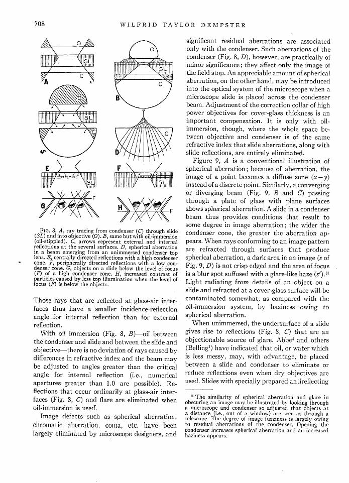
WILFRID TAYLOR DEMPSTER
FIG. 8. A, ray tracing from condenser (C) through slide(SL) and into objective (0). B, same but with oil-immersion(oil-stippled). C, arrows represent external and internalreflections at the several surfaces. D, spherical aberrationin a beam emerging from an unimmersed condenser toplens. E, centrally directed reflections with a high condensercone. F, peripherally directed reflections with a low con-denser cone. G, objects on a slide below the level of focus(F) of a high condenser cone. H, increased contrast ofparticles caused by less top illumination when the level offocus (F) is below the objects.
Those rays that are reflected at glass-air inter-faces thus have a smaller incidence-reflectionangle for internal reflection than for externalreflection.
With oil immersion (Fig. 8, B)-oil betweenthe condenser and slide and between the slide andobjective-there is no deviation of rays caused bydifferences in refractive index and the beam maybe adjusted to angles greater than the criticalangle for internal reflection (i.e., numericalapertures greater than 1.0 are possible). Re-flections that occur ordinarily at glass-air inter-faces (Fig. 8, C) and flare are eliminated whenoil-immersion is used'.
Image defects such as spherical aberration,chromatic aberration, coma, etc. have beenlargely eliminated by microscope designers, and
significant residual aberrations are associatedonly with the condenser. Such aberrations of thecondenser (Fig. 8, D), however, are practically ofminor significance; they affect only the image ofthe field stop. An appreciable amount of sphericalaberration, on the other hand, may be introducedinto the optical system of the microscope when amicroscope slide is placed across the condenserbeam. Adjustment of the correction collar of highpower objectives for cover-glass thickness is animportant compensation. It is only with oil-immersion, though, where the whole space be-tween objective and condenser is of the samerefractive index that slide aberrations, along withslide reflections, are entirely eliminated.
Figure 9, A is a conventional illustration ofspherical aberration; because of aberration, theimage of a point becomes a diffuse zone (x-y)instead of a discrete point. Similarly, a convergingor diverging beam (Fig. 9, B and C) passingthrough a plate of glass with plane surfacesshows spherical aberration. A slide in a condenserbeam thus provides conditions that result tosome degree in image aberration; the wider thecondenser cone, the greater the aberration ap-pears. When rays conforming to an image patternare refracted through surfaces that producespherical aberration, a dark area in an image (s ofFig. 9, D) is not crisp edged and the area of focusis a blur spot suffused with a glare-like haze (). 11
Light radiating from details of an object on aslide and refracted at a cover-glass surface will becontaminated somewhat, as compared with theoil-immersion system, by haziness owing tospherical aberration.
When unimmersed, the undersurface of a slidegives rise to reflections (Fig. 8, C) that are anobjectionable source of glare. Abbe4 and others(Bellingi) have indicated that oil, or water whichis less messy, may, with advantage, be placedbetween a slide and condenser to eliminate orreduce reflections even when dry objectives areused. Slides with specially prepared antireflecting
31 The similarity of spherical aberration and glare inobscuring an image may be illustrated by looking througha microscope and condenser so adjusted that objects ata distance (i.e., out of a window) are seen as through atelescope. The degree of image fuzziness is largely owingto residual aberrations of the condenser. Opening thecondenser increases spherical aberration and an increasedhaziness appears.
708
XH,\171��//_ r- F
E � <��J -- -_111111yA\/L C

PRINCIPLES OF MICROSCOPE ILLUMINATION
coatings3 2 reduce glare perceptibly though theyare not of as much value as condenser immersion,using oil.
Glare at unimmersed cover-glass surfaces owingto internal reflection (Fig. 8, C) may be reducedto a large extent by careful adjustment of thelevel of condenser focus. When the condenser isracked up so that the converging beam reflects(by internal reflection) on the cover-glass surface,light is reflected centrally (Fig. 8, E) and a brightcentral spot or a glaring annulus partly obscuresthe field of view. The object, in effect, is illumi-nated both by transmitted light and by direct
x Y
FIG. 9. Ray tracing through a lens showing sphericalaberration. Focus level is over the span X-Y. B, rays con-verging to a focus at 0 are distorted by spherical aberrationwhen a flat plate is interposed and the focus spreadsbetween X and Y. C, rays diverging from a point (0) aredistorted in traversing a plate so that the projections ofthe emerging rays intersect between X and Y. D, sphericalaberration of a lens with a zone of focus at X-Y. Point Sis projected to level R as a blur circle of the size shownat S'.
32 Several slides, coated by the Cartwright method(reference 29), were prepared for me through the kindnessof Professor R. C. Williams. When light of an appropriatecolor was used, a slight but perceptible decrease in glarewas evident. Since coated slides do not alter the amount ofinternal reflection, the major problem remains.
light. When the level of the condenser focus isslightly below the cover-glass surface (Fig. 8, F),reflections are thrown peripherally and do notobscure the field.
Shillaber indicates a special source of glarefound chiefly in the examination of crystals.Here, reflection from one crystal to anotherneighboring crystal may cause a mixture oftransmitted and reflected light as well as glare.In biological work, the glare effects of lightscattered in a tissue are less serious.
Eye Glare
The last type of glare to be mentioned arisesexternal to the optical system of the microscopeand in a strict sense is limited to visual workwith the microscope. Glare may be added tothe visual image by extraneous light enteringthe eye from the side (i.e., from the peripheryof the field of vision) or by reflections from thetop of the ocular or from spectacle lenses. Thistype of glare is in part analogous to the foggingdefect in photomicrography caused by cracks ina camera bellows. In addition, however, spotglare sources have a pernicious effect on visualefficiency because of peculiarities of the psycho-physiology of the eye. Such glare affecting theeyes may, of course, be eliminated by the use ofan eyeshade, but, it should be noted, totalexclusion of peripheral light is not ideal sincedark surroundings provide conditions incom-patible with superior visual acuity. This problemis the subject of a further paper.2 7
OBJECT CONTRAST
Minute solid particles with reflecting surfaces-fine pumice, scrapings of dried India ink, ortiny globules of mercury-if placed on a slidein a widely converging beam, are illuminated ontheir sides and, to some extent, on their uppersurfaces (Fig. 8, G). Their profiles as seen in themicroscope are not clear. In a diverging beam,on the other hand (Fig. 8, H), the upper surfaceis less illuminated and the particles show as if insilhouette. With light absorbing particles (stainedspecimens), the silhouette effect is likewise ac-centuated when the level of the condenser focusis just below the object level. The adjustment isdesirable with both dry and oil immersion ob-jectives. Beck' indicates that more lines per inch
709

WILFRID TAYLOR DEMPSTER
are resolved in test gratings if the condenserfocus is slightly below the grating level than ifthe focus level coincides with or is above thegrating level.
Constriction of the condenser iris decreases theobliquity of the illuminating rays emerging fromthe condenser, and the microscope image showsincreasing contrast of edges and a decrease inhaze. The upper lens of an objective, however,as seen through the draw tube, shows a darkperiphery and indicates a decrease in the workingN.A. of the objective and a resultant decreasein the conditions for high resolution. Decrease inbeam obliquity below the aperture requirementsof an objective may be expected to decrease theglare-like effects of spherical aberration, reducethe amount of lenticular glare, and reduce thepossibility of side and top illumination of objectsin the field of view. Both reflecting and lightabsorbing objects show increasingly dark con-tours. With refractile objects like diatoms, how-ever, the nature of the surface configuration andthe refractive index of the mounting mediumalter the distribution of the emergent light andthe resultant microscopical appearance changesas the obliquity of the light is changed. Evenhere, if the medium is of suitable refractiveindex, the general contrast is enhanced by lightof less obliquity than required to fill the ob-jective.
In general, contrast appears to be highest andglare the lowest when the condenser iris is con-stricted to an N.A. value of about a third thatof the objective used. When the condenser isreduced in this way, a beam roughly like that ofFig. 6, C, or a beam intermediate to those shown
at C and F is produced. With such a beam, thecentral rather than the peripheral parts of theobjective are used in image production. Imagesof both the field diaphragm and condenserdiaphragm impinge on the beam (Fig. 6, C) andthe diverging cone so limited is in a sense pro-jected through the objective lenses with aminimum of stray light. This modification ofcontrolled illumination may be called contrastillumination.
Further constriction of the condenser irisgives rise to diffraction effects-alternate lightand dark bands bounding the contours of objects-such as those illustrated in Fig. 1, II and G. Asthe iris is opened, the contour bands fade andmaximum edge sharpness and contrast appeargreatest when the dark bands have just faded.
In practical microscopy, the condenser irisshould be toyed with constantly so that contrastand controlled or intermediate degrees of illumi-nation are employed in varying sequence. Somemethod of increasing and decreasing illuminantbrightness apart from the condenser should beavailable, too. Through condenser adjustments,the observer provides his eye with fresh visualimpressions of an object. Apart from brightnessdifferences, variations in the condenser iris pro-duce differences in resolving power, in objectcontrast, and in the depth of focus perceivableby a given objective (Fig. 1). In photomicrog-raphy, a desirable compromise involving thesefactors is to be sought by condenser adjustment.Though a three-quarters to nine-tenths apertureis a common compromise, it is best in practiceto regulate the condenser till the exact appear-ance sought (Fig. 1) shows in the ground glass.
710