principles of electric machines and power electronicsli/slides/ch02-3sli.pdfprinciples of electric...
TRANSCRIPT

Copyright © 2014 John Wiley & Sons, Inc. All rights reserved.
Chapter 2-3Transformers
Third Edition
P. C. Sen
Principles of Electric Machines
and
Power Electronics
Copyright © 2014 John Wiley & Sons, Inc. All rights reserved.
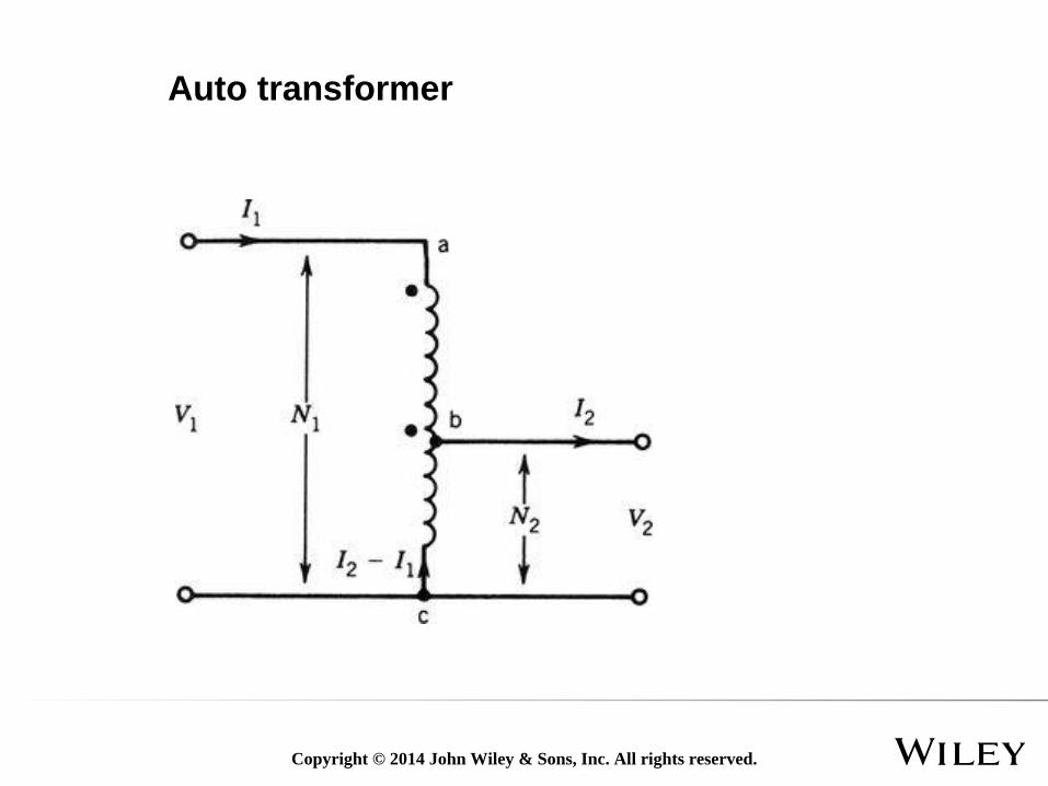
Auto transformer
Copyright © 2014 John Wiley & Sons, Inc. All rights reserved.Fig_2-15
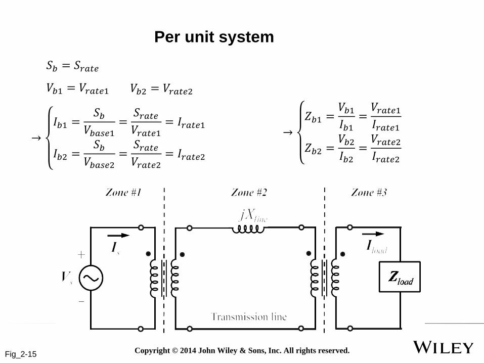
Per unit system
𝑆𝑏 = 𝑆𝑟𝑎𝑡𝑒
𝑉𝑏1 = 𝑉𝑟𝑎𝑡𝑒1 𝑉𝑏2 = 𝑉𝑟𝑎𝑡𝑒2
→
𝐼𝑏1 =𝑆𝑏
𝑉𝑏𝑎𝑠𝑒1=
𝑆𝑟𝑎𝑡𝑒𝑉𝑟𝑎𝑡𝑒1
= 𝐼𝑟𝑎𝑡𝑒1
𝐼𝑏2 =𝑆𝑏
𝑉𝑏𝑎𝑠𝑒2=
𝑆𝑟𝑎𝑡𝑒𝑉𝑟𝑎𝑡𝑒2
= 𝐼𝑟𝑎𝑡𝑒2
→
𝑍𝑏1 =𝑉𝑏1𝐼𝑏1
=𝑉𝑟𝑎𝑡𝑒1𝐼𝑟𝑎𝑡𝑒1
𝑍𝑏2 =𝑉𝑏2𝐼𝑏2
=𝑉𝑟𝑎𝑡𝑒2𝐼𝑟𝑎𝑡𝑒2

Copyright © 2014 John Wiley & Sons, Inc. All rights reserved.Fig_1-1
Chapter 2 Main contents (continued)
•Main contentsBalanced three phase system
Three-phase transformer
Copyright © 2014 John Wiley & Sons, Inc. All rights reserved.Fig_2-17
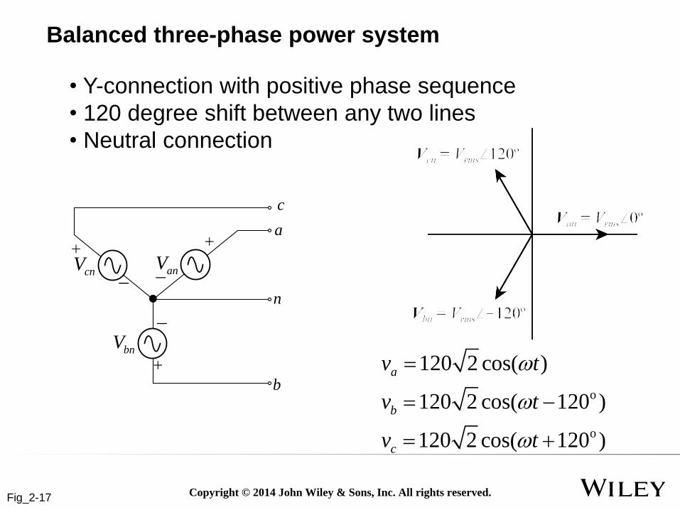
Balanced three-phase power system
• Y-connection with positive phase sequence
• 120 degree shift between any two lines
• Neutral connection
cnV
c
anV
bnV
a
n
bo
o
120 2 cos( )
120 2 cos( 120 )
120 2 cos( 120 )
a
b
c
v t
v t
v t

Copyright © 2014 John Wiley & Sons, Inc. All rights reserved.
a1 a2
b1
b2
c1
c2
a-b-c-a-b-c c-b-a-c-b-a
a b c c b a
Phase sequence

Copyright © 2014 John Wiley & Sons, Inc. All rights reserved.Fig_2-17
Three-phase Y-source
• Y-connection: line to line variables
Line-to line voltages

Copyright © 2014 John Wiley & Sons, Inc. All rights reserved.
𝑉𝑎𝑏 = 𝑉𝑎𝑛 − 𝑉𝑏𝑛
= 2𝑉𝑟𝑚𝑠 cos𝜔𝑡 − 2𝑉𝑟𝑚𝑠 cos(𝜔𝑡 − 120°)
= 2𝑉𝑟𝑚𝑠 (cos𝜔𝑡 − cos(𝜔𝑡 − 120°))
= 2𝑉𝑟𝑚𝑠 (−2sin𝜔𝑡+(𝜔𝑡−120°)
2sin
𝜔𝑡−(𝜔𝑡−120°)
2)
= 2𝑉𝑟𝑚𝑠 (−2sin(𝜔𝑡 − 60°) sin 60°)
= 2𝑉𝑟𝑚𝑠 (2 cos(𝜔𝑡 + 30°)3
2)
= 2𝑉𝑟𝑚𝑠 3 cos(𝜔𝑡 + 30°)
Deriving line to line voltages

Copyright © 2014 John Wiley & Sons, Inc. All rights reserved.Fig_2-17
Three-phase Y-source
•Phase voltage: voltage per source
•Line voltage: voltage between output terminals
•Phase current: current per source
•Line current: current of one transmission line between source and load
•Y-source: phase current = line current
YZ
cnV
c
anV
bnV
a
n
b
A
C
N
B
YZYZ
lZ
lZ
lZcCI
aAI
bBI
nI
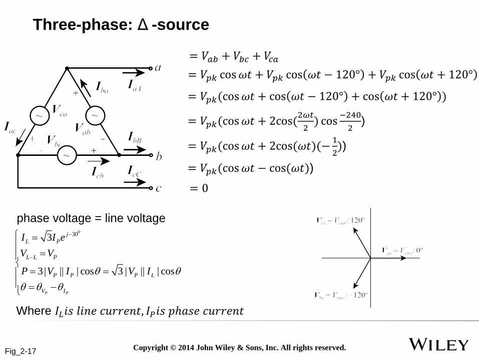
0303
3 | || | cos 3 | || | cos
P P
P L
j
L L P
P P L L P
V I
I I
V V e
P V I V I
Three phase load
Copyright © 2014 John Wiley & Sons, Inc. All rights reserved.Fig_2-17
Three-phase: Δ -source
0303
3 | || | cos 3 | || | cos
P P
j
L P
L L P
P P P L
V I
I I e
V V
P V I V I
= 𝑉𝑝𝑘 cos𝜔𝑡 + 𝑉𝑝𝑘 cos 𝜔𝑡 − 120° + 𝑉𝑝𝑘 cos 𝜔𝑡 + 120°
= 𝑉𝑝𝑘(cos𝜔𝑡 + cos 𝜔𝑡 − 120° + cos 𝜔𝑡 + 120° )
phase voltage = line voltage
= 𝑉𝑝𝑘(cos𝜔𝑡 + 2cos(2𝜔𝑡
2) cos
−240
2)
= 𝑉𝑝𝑘(cos𝜔𝑡 + 2cos(𝜔𝑡)(−1
2))
= 𝑉𝑝𝑘(cos𝜔𝑡 − cos(𝜔𝑡))
= 0
Where 𝐼𝐿𝑖𝑠 𝑙𝑖𝑛𝑒 𝑐𝑢𝑟𝑟𝑒𝑛𝑡, 𝐼𝑃𝑖𝑠 𝑝ℎ𝑎𝑠𝑒 𝑐𝑢𝑟𝑟𝑒𝑛𝑡
= 𝑉𝑎𝑏 + 𝑉𝑏𝑐 + 𝑉𝑐𝑎

Copyright © 2014 John Wiley & Sons, Inc. All rights reserved.Fig_2-17
Δ-Y transformation of source
0( 30 )3
aba Y
VV
• Use Y source to replace Δ source
• Maintain same Vl-l and Il
𝐼𝑎 = 3𝐼𝑏𝑎𝑒𝑗(−30°)
𝑉𝑎𝑏 = 3𝑉𝑎𝑛𝑒𝑗30°
𝐼𝑎𝑏 =𝐼𝑏𝑎
3𝑒𝑗(30°)

Copyright © 2014 John Wiley & Sons, Inc. All rights reserved.Fig_2-17
Three-phase load
• phase current = line current
• phase voltage=line to line voltage

Copyright © 2014 John Wiley & Sons, Inc. All rights reserved.Fig_2-17
Δ-Y transformation of load
𝑍∆ =𝑉𝐴𝐵𝐼𝐴𝐵
= 3𝑒𝑗(−30°)𝑉𝐴𝐵𝐼𝑎𝐴
𝑉𝐴𝑁 =𝑉𝐴𝐵
3𝑒𝑗(−30°)
𝑍𝑌 =𝑉𝐴𝑁𝐼𝑎𝐴
=𝑒𝑗(−30°)
3
𝑉𝐴𝐵𝐼𝑎𝐴
𝑍𝑌𝑍∆
=1
3
• With same Vl-l and Il
• Find the relation between Y load and Δ load

Copyright © 2014 John Wiley & Sons, Inc. All rights reserved.Fig_2-17
Balanced three-phase power system
• Per-phase analysis of balanced three-phase systemBalanced voltage sources
Balanced line and load impedances
Balanced resulting currents
For Y-source and Y-load (Y- Y), we have
aVYZ
lZ
n N
an bn cn 0V V V
a b c 0nI I I I
YZ
cnV
c
anV
bnV
a
n
b
A
C
N
B
YZYZ
lZ
lZ
lZcCI
aAI
bBI
nI

Copyright © 2014 John Wiley & Sons, Inc. All rights reserved.Fig_2-17
Balanced three-phase power system
• How to analyze other types of three-phase source-power
connection (Page 14, reference materials)
Y- Δ
Δ-Y
Δ- Δ
•Solution: transform to Y-Y connection and apply per-phase
analysis
•During transformation, keep two variables unchanged
Line to line voltage
Line current
As a result: power is conservative

Copyright © 2014 John Wiley & Sons, Inc. All rights reserved.Fig_2-17
Power of balanced three-phase loads
•Instantaneous power is constant, and equal to average
power

Copyright © 2014 John Wiley & Sons, Inc. All rights reserved.
Simulation: Power of balanced three-phase loads and
single phase load
1. Show phase voltage and phase current
2. Show line voltage
3. Show neutral voltage add to zero
4. Show single phase power/three phase power
Copyright © 2014 John Wiley & Sons, Inc. All rights reserved.Fig_2-17
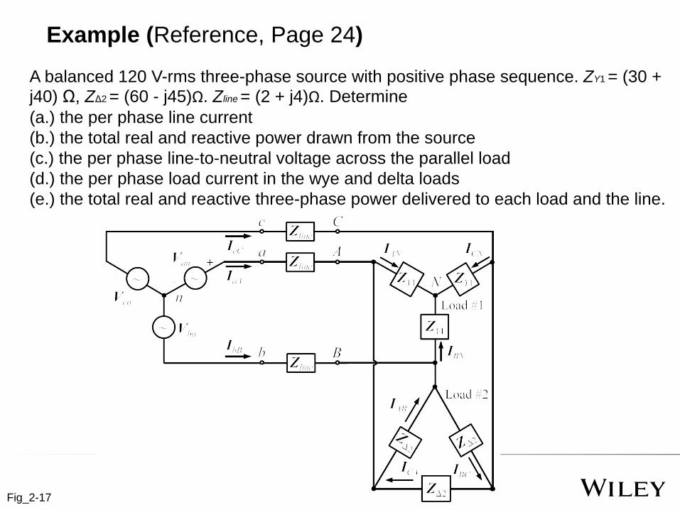
Example (Reference, Page 24)
A balanced 120 V-rms three-phase source with positive phase sequence. ZY1 = (30 + j40) Ω, ZΔ2 = (60 - j45)Ω. Zline = (2 + j4)Ω. Determine
(a.) the per phase line current
(b.) the total real and reactive power drawn from the source
(c.) the per phase line-to-neutral voltage across the parallel load
(d.) the per phase load current in the wye and delta loads
(e.) the total real and reactive three-phase power delivered to each load and the line.