principles of direct sequence & frequency hopping …...principles of direct sequence &...
TRANSCRIPT

Principles ofDirect Sequence & Frequency Hopping SSS
Professor A. Manikas
Imperial College London
EE303 - Communication SystemsAn Overview of Fundamentals
Prof. A. Manikas (Imperial College) EE303: DS & FH SSS 30 Nov 2011 1 / 77

Table of Contents1 Introduction
Modelling of PN-signals in SSSEquivalent Energy Unitisation E¢ciency (EUE)Comments
2 Classification of Jammers in SSS3 Direct Sequence SSS
Introductory Concepts and Mathematical ModellingPSD(f ) of a Random Pulse SignalPSD(f ) of a PN-Signal b(t) in DS-SSSsPSD(f ) of DS/BPSK Spread Spectrum Tx Signal s(t)
4 DS-BPSK Spread SpectrumOutput SNIRBit Error Probability with Jamming
5 DS-SSS on the (pe , EUE, BUE)-parameter plane6 Anti-Jam Margin7 Some Comments on DS-QPSK-SSS8 Frequency Hopping SSSs9 Appendices
Appendix A. Block Diagram of a Typical Spread Spectrum SystemAppendix B. BPSK/DS/SS Transmitter and ReceiverAppendix C. QPSK/DS/SS Transmitter and ReceiverAppendix D. Proof of SNIRout (Equation 27)
Prof. A. Manikas (Imperial College) EE303: DS & FH SSS 30 Nov 2011 2 / 77

Introduction
Introduction
(a) SSS (jammers): (b) CDMA (K users):
Prof. A. Manikas (Imperial College) EE303: DS & FH SSS 30 Nov 2011 3 / 77

Introduction Modelling of PN-signals in SSS
Modelling of PN-signals in SSSConsider
!
({α[n]}=a sequence of ± 10sc(t) = an energy signal of duration Tc , e.g. c(t) = rect
ntTc
o
We have seen that the PN signal b(t) can be modelled as follows:I DS-SSS (Examples: DS-BPSK, DS-QPSK):
b(t) = ∑n
α[n].c(t ! nTc ) (1)
I FH-SSS (Examples: FH-FSK)
b(t) = ∑nexp {j(2πk[n]F1t + φ[n])} .c(t ! nTc ) (2)
where {k[n]} is a sequence of integers such that
{α[n]} 7! {k[n]} (3)
and with φ[n] = random: pdfφ[n] =12π rect
n12π
o
Prof. A. Manikas (Imperial College) EE303: DS & FH SSS 30 Nov 2011 4 / 77

Introduction Equivalent Energy Unitisation E¢ciency (EUE)
Equivalent Energy Unitisation E¢ciency (EUE)Remember:
F Jamming source, or, simply Jammer = intentional interferenceF Interfering source = unintentional interference
F With area-B = area-A we can find NjF Pj = 2% areaA = 2% areaB = NjBj ) Nj =
PjBj
Prof. A. Manikas (Imperial College) EE303: DS & FH SSS 30 Nov 2011 5 / 77

Introduction Equivalent Energy Unitisation E¢ciency (EUE)
ifBJ = qBss ; 0 < q ' 1 (4)
then
EUEJ =EbNJ
=Ps .BJPJ .rb
=Ps .q.BssPJ .B
= PG% SJRin % q (5)
EUEequ =Eb
N0 +NJ(6)
= PG% SJRin % q| {z }EUEj
%(N0Nj+ 1
)!1(7)
where
SJRin ,PsPJ
(8)
Prof. A. Manikas (Imperial College) EE303: DS & FH SSS 30 Nov 2011 6 / 77

Introduction Comments
CommentsEUEequ (or EUEJ ): very important since bit error probabilities aredefined as function of EUEequ (or of EUEJ )For a specified performance
!*the smaller the SIRin ) the better for the signalthe larger the SIRin ) the better for the jammer
Jammer limits the performance of the communication systemi.e. e§ects of channel noise can be ignoredi.e. Jammer Power( Pn ) EUEequ =
EbN0+NJ
' EbNJ= EUEJ
""
N.B. exception to this:i) non-uniform fading channelsii) multiple access channels
9 ∞ number of possible jamming waveformsThere is no single jamming waveform that is worst for all SSSsThere is no single SSS that is best against all jamming waveforms.
Prof. A. Manikas (Imperial College) EE303: DS & FH SSS 30 Nov 2011 7 / 77

Classification of Jammers in SSS
Classification of Jammers in SSS
Prof. A. Manikas (Imperial College) EE303: DS & FH SSS 30 Nov 2011 8 / 77
Direct Sequence SSS Introductory Concepts and Mathematical Modelling
Direct Sequence SSSIntroductory Concepts & Mathematical Modelling
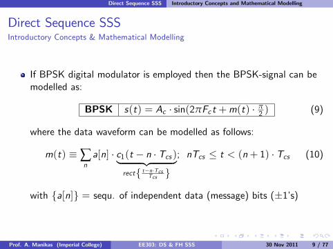
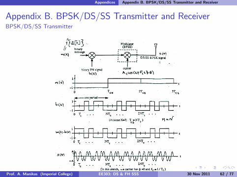
If BPSK digital modulator is employed then the BPSK-signal can bemodelled as:
BPSK s(t) = Ac · sin(2πFc t +m(t) · π2 ) (9)
where the data waveform can be modelled as follows:
m(t) , ∑na[n] · c1(t ! n · Tcs )| {z }
rect{ t!n·TcsTcs }
; nTcs ' t < (n+ 1) · Tcs (10)
with {a[n]} = sequ. of independent data (message) bits (±1’s)
Prof. A. Manikas (Imperial College) EE303: DS & FH SSS 30 Nov 2011 9 / 77

Direct Sequence SSS Introductory Concepts and Mathematical Modelling
Equation (9) can be rewritten as follows:
BPSK s(t) = Ac ·m(t) · cos(2πFc t)
) BPSK can be considered as(
PMAM
(11)
remember:
Prof. A. Manikas (Imperial College) EE303: DS & FH SSS 30 Nov 2011 10 / 77

Direct Sequence SSS Introductory Concepts and Mathematical Modelling
The PSD(f )’s of m(t) and s(t) are shown below
Prof. A. Manikas (Imperial College) EE303: DS & FH SSS 30 Nov 2011 11 / 77

Direct Sequence SSS Introductory Concepts and Mathematical Modelling
If a DS/BPSK modulator is employed, then the SS-transmitted signalis
DS/BPSK : s(t) = Ac sin
0
@2πFc t +
±1z }| {m(t)b(t)
π
2
1
A (12)
= Acm(t)b(t) cos(2πFc t) (13)
where
8>>>>>>>>>><
>>>>>>>>>>:
m(t) , ∑na[n] · c1(t ! nTcs )| {z }
"rect{ t!nTcsTcs }
; nTcs ' t < (n+ 1)Tcs
b(t) = ∑k
α[k ] · c2(t ! kTcs )| {z }"
rect{ t!kTcTc }
; kTc ' t <
chip-duration
(k + 1)#Tc
3333333333333333
(14)
Prof. A. Manikas (Imperial College) EE303: DS & FH SSS 30 Nov 2011 12 / 77

Direct Sequence SSS Introductory Concepts and Mathematical Modelling
BPSK DS/CDMA Transmitter & Receiver
TX (see also Appendix-B):
Rx (see also Appendix-B):
Prof. A. Manikas (Imperial College) EE303: DS & FH SSS 30 Nov 2011 13 / 77

Direct Sequence SSS Introductory Concepts and Mathematical Modelling
The PN-sequence {α[l ]} (whose elements have values ±1)
is M times faster than the data sequence {α[n]} .
i.e.Tcs = M · Tc (15)
i.e.PN-signal Bandwidth ( data-Bandwidth (16)
Prof. A. Manikas (Imperial College) EE303: DS & FH SSS 30 Nov 2011 14 / 77

Direct Sequence SSS Introductory Concepts and Mathematical Modelling
Systems which have coincident data and SS code clocks
are often said to have a “data privacy feature”I such systems are easy to build and can be combined in single units
Tcs =
5qMTc
Note: chip = Tc = smallest time increment
Prof. A. Manikas (Imperial College) EE303: DS & FH SSS 30 Nov 2011 15 / 77

Direct Sequence SSS Introductory Concepts and Mathematical Modelling
If the above “data privacy feature” is taken into account
then8>>>><
>>>>:
m(t) , ∑na[n].c1(t ! n · Tcs ) nTcs < t < (n+ 1)Tcs
b(t) = ∑k
α[k ].c2(t ! kTc ) kTc < t < (k + 1)Tc
with Tcs = MTc ;4 kM
5= n;
(17)
where
n · Tcs + k 0 · Tc ' t < n · Tcs + (k 0 + 1) · Tc8k 0 = 0, 1, . . . ,M ! 1 = kmodM
Prof. A. Manikas (Imperial College) EE303: DS & FH SSS 30 Nov 2011 16 / 77
Direct Sequence SSS Introductory Concepts and Mathematical Modelling
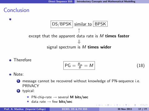
Conclusion
DS/BPSK similar to BPSK"
except that the apparent data rate is M times faster+
signal spectrum is M times wider
ThereforePG = Bss
B = M (18)
Note:1 message cannot be recovered without knowledge of PN-sequence i.e.PRIVACY
2 typical:F PN-chip-rate ! several M bits/secF data rate ! few bits/sec
Prof. A. Manikas (Imperial College) EE303: DS & FH SSS 30 Nov 2011 17 / 77

Direct Sequence SSS Introductory Concepts and Mathematical Modelling
PSD of DS/BPSK/SS Transmitted Signal
Tx signal
s(t) = m(t) · b(t) · Ac · cos(2πFc t)
+PSDs (f ) = PSDm(f ) 0 PSDb(f ) 0 PSDAc cos(2πFc t)(f )
+PSDs (f ) = PSDm(f ) 0 PSDb(f ) 0 PSDAc cos(2πFc t)(f )
remember
PSDAc cos(2πFc t)(f ) =A2c4· (δ (f ! Fc ) + δ (f + Fc ))
Prof. A. Manikas (Imperial College) EE303: DS & FH SSS 30 Nov 2011 18 / 77

Direct Sequence SSS PSD(f ) of a Random Pulse Signal
PSD(f) of a Random Pulse SignalFor a random pulse signal m(t) (i.e. a sequence of pulses where thereis an invariant average time of separation Tcs between pulses) with allpulses of the same form but with random amplitudes and statisticalindependent random time of occurrence, then:
PSDm(f ) =1Tcs
· En|Fourier Transform of a single pulse|2
o
Prof. A. Manikas (Imperial College) EE303: DS & FH SSS 30 Nov 2011 19 / 77

Direct Sequence SSS PSD(f ) of a Random Pulse Signal
Example: PSD of a random BINARY signal m(t)Consider a random binary sequence of 0’s and 1’s. This binarysequence is transmitted as random signal m(t) with 1’s and 0’s beingsent using the pulses shown below.
For instance a random binary sequence/waveform could be
If 1’s and 0’s are statistically independent with Pr(0) = Pr(1) = 0.5,the PSD of the transmitted signal can be estimated as follows:
Prof. A. Manikas (Imperial College) EE303: DS & FH SSS 30 Nov 2011 20 / 77

Direct Sequence SSS PSD(f ) of a Random Pulse Signal
Solution:
PSDm(f ) =1Tcs
· E
8<
:
666666FT
0
@
1
A
666666
29=
;
=1Tcs
· E:a2 · T 2cs · sinc
2(fTcs );
=1Tcs
· T 2cs · sinc2 {fTcs} · E
:a2;
| {z }=(!A2) 12+(+A2)
12
= TcsA2 sinc2 {fTcs}
Rmm(τ) = ? for you!
Prof. A. Manikas (Imperial College) EE303: DS & FH SSS 30 Nov 2011 21 / 77

Direct Sequence SSS PSD(f ) of a PN-Signal b(t) in DS-SSSs
PSD(f) of a PN-Signal b(t) in DS-SSSsAutocorrelation function: Rbb(τ) = 1
NcTcRcc (τ)~ Rαα(τ)
where c(t) =rect tTc =
1 Rcc (τ) = TcΛ( τTc)
2 Rαα(τ) , (Nc + 1)repNcTc {δ(τ)}!repTc {δ(τ)}
3 autocorrelation function Rbb(τ) =1
NcTcRcc (τ)~ Rαα(τ)
Prof. A. Manikas (Imperial College) EE303: DS & FH SSS 30 Nov 2011 22 / 77

Direct Sequence SSS PSD(f ) of a PN-Signal b(t) in DS-SSSs
i.e.
Rbb(τ) =1
NcTcRcc (τ)~ Rαα(τ)
=1
NcTc(Nc + 1)repNcTc
*TcΛ
(τ
Tc
)<
!1
NcTcrepTc
*TcΛ
(τ
Tc
)<
=Nc + 1Nc
· repNcTc
*Λ(
τ
Tc
)<!1Nc
Prof. A. Manikas (Imperial College) EE303: DS & FH SSS 30 Nov 2011 23 / 77

Direct Sequence SSS PSD(f ) of a PN-Signal b(t) in DS-SSSs
Thus, we have
Rbb(τ) =Nc+1Nc
repNcTcn
Λ=
τTc
>o! 1
Nc(19)
By using the FT tables the PSD(f )= FT{Rbb(τ)} of the signal b(t)is:
PSDb(f ) =Nc+1N 2c
comb 1Nc Tc
:sinc2 {f · Tc}
;! 1
Ncδ(f ) (20)
Prof. A. Manikas (Imperial College) EE303: DS & FH SSS 30 Nov 2011 24 / 77

Direct Sequence SSS PSD(f ) of DS/BPSK Spread Spectrum Tx Signal s(t)
PSD(f) of DS/BPSK Spread Spectrum Tx Signal s(t)
s(t) = m(t) · b(t) · Ac · cos(2πFc t)
) PSDs (f ) = PSDm(f ) 0 PSDb(f ) 0A2c4 (δ(f ! Fc ) + δ(f + Fc ))| {z }
term 1
Ignore (for the time being) the e§ects of m(t)
PSDterm1(f ) = A2c4 · PSDb(f ) 0 (δ(f ! Fc ) + δ(f + Fc ))
= A2c4 ·*Nc+1N 2c
· comb 1Nc Tc
:sinc2(f · Tc )
;!1Nc· δ(f )
<
0 (δ(f ! Fc ) + δ(f + Fc ))
= A2c4 ·
Nc+1N 2c
·=comb 1
Nc Tc
:sinc2 {(f ! Fc )Tc}
;
+ comb 1Nc Tc
:sinc2 {(f + Fc )Tc}
;>
!A2c4
1Nc(δ(f ! Fc ) + δ(f + Fc ))
Prof. A. Manikas (Imperial College) EE303: DS & FH SSS 30 Nov 2011 25 / 77

Direct Sequence SSS PSD(f ) of DS/BPSK Spread Spectrum Tx Signal s(t)
i.e.
PSDterm1(f ) =A2c4·Nc + 1N2c
·=comb 1
Nc Tc
:sinc2 {(f ! Fc )Tc}
;
+ comb 1Nc Tc
:sinc2 {(f + Fc )Tc}
;>
!A2c41Nc(δ(f ! Fc ) + δ(f + Fc )) (21)
Prof. A. Manikas (Imperial College) EE303: DS & FH SSS 30 Nov 2011 26 / 77

Direct Sequence SSS PSD(f ) of DS/BPSK Spread Spectrum Tx Signal s(t)
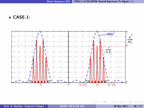
Above the e§ects of m(t) have not been taken into account.I If m(t) is used,then each discrete frequency in Equation (21) becomes a sinc2
function.I There are two cases:
CASE-1:
1Tcs< 1
2NcTc
CASE-2:
1Tcs1 1
NcTc
the peaks will merge into acontinuous smooth spectrum
Prof. A. Manikas (Imperial College) EE303: DS & FH SSS 30 Nov 2011 27 / 77
Direct Sequence SSS PSD(f ) of DS/BPSK Spread Spectrum Tx Signal s(t)
CASE-1:
Prof. A. Manikas (Imperial College) EE303: DS & FH SSS 30 Nov 2011 28 / 77

Direct Sequence SSS PSD(f ) of DS/BPSK Spread Spectrum Tx Signal s(t)
CASE-2:
Prof. A. Manikas (Imperial College) EE303: DS & FH SSS 30 Nov 2011 29 / 77

Direct Sequence SSS PSD(f ) of DS/BPSK Spread Spectrum Tx Signal s(t)
N.B.:I If
b(t) = random
thens(t) = Acm(t)b(t) cos(2πFc t)
I If the e§ects of m(t) are ignored then
PSDs (f ) = A2cT2c sinc {fTc} 0
14(δ(f ! Fc ) + δ(f + Fc ))
+
PSDs (f ) =Tc4A2c=sinc2 {(f ! Fc )Tc}+ sinc2 {(f + Fc )Tc}
>
i.e. PSD is similar to ‘CASE-2’ above
Prof. A. Manikas (Imperial College) EE303: DS & FH SSS 30 Nov 2011 30 / 77

DS-BPSK Spread Spectrum Output SNIR
DS-BPSK Spread Spectrum:Output SNIR
Consider the block diagram of a SS-Communication System whichemploys a BPSK digital modulator:
Prof. A. Manikas (Imperial College) EE303: DS & FH SSS 30 Nov 2011 31 / 77

DS-BPSK Spread Spectrum Output SNIR
N.B.: Bss = 1Tc; B = 1
Tcs; PG = Bss
B = TcsTc
Then, at point T1 , we have
s(t) = Ac ·m(t) · b(t) · cos(2πFc t) (22)
and at point^T1 :
s(t) + n(t) + j(t) (for k = 1) (23)
At the input of the receiver the Signal-to-Noise-plus-InterferenceRatio (SNIRin) is:
SNIRin =EUE
PG · (1+ JNRin)=EUEequPG
(24)
Prof. A. Manikas (Imperial College) EE303: DS & FH SSS 30 Nov 2011 32 / 77

DS-BPSK Spread Spectrum Output SNIR
at point^T :
(s(t) + n(t) + j(t)) · b(t ! τ) · 2 cos(2πFc t + θ) (25)
at point T0 :
From the analysis presented in Appendix-D we have
Punwanted =
8><
>:
N0Tcs+ A2c
Tcs ·Tc · τ2 · cos2(θ) + Pjout for |τ| ' Tc
N0Tcs+ A2c ·Tc
Tcs· cos2(θ) + Pjout for |τ| > Tc
3333333(26)
Prof. A. Manikas (Imperial College) EE303: DS & FH SSS 30 Nov 2011 33 / 77
DS-BPSK Spread Spectrum Output SNIR
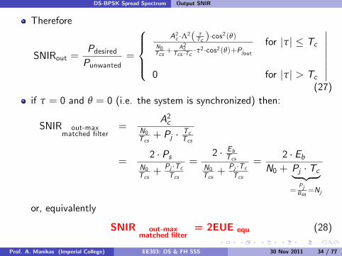
Therefore
SNIRout =PdesiredPunwanted
=
8>><
>>:
A2c ·Λ2( τTc )·cos
2(θ)
N0Tcs+ A2cTcs ·Tc ·τ
2 ·cos2(θ)+Pjoutfor |τ| ' Tc
0 for |τ| > Tc
33333333(27)
if τ = 0 and θ = 0 (i.e. the system is synchronized) then:
SNIR out-maxmatched filter
=A2c
N0Tcs+ Pj · TcTcs
=2 · Ps
N0Tcs+
Pj ·TcTcs
=2 · EbTcs
N0Tcs+
Pj ·TcTcs
=2 · Eb
N0 + Pj · Tc| {z }=
PjBss=Nj
or, equivalently
SNIR out-maxmatched filter
= 2EUE equ (28)
Prof. A. Manikas (Imperial College) EE303: DS & FH SSS 30 Nov 2011 34 / 77

DS-BPSK Spread Spectrum Output SNIR
However (see Equation 48, Appendix D),
SNIRin =EUE
PG · (1+ JNRin)=EUEequPG
(29)
Therefore,
SNIR out-maxmatched filter
= 2EUEequ= 2.PG.SNIRin (30)
Prof. A. Manikas (Imperial College) EE303: DS & FH SSS 30 Nov 2011 35 / 77

DS-BPSK Spread Spectrum Bit Error Probability with Jamming
Bit Error Probability with Jamming
A. CONSTANT POWER BROADBAND JAMMER:
From the “Detection Theory” topic we know that thebit-error-probability pe for a Binary Phase-Shift Key (BPSK)communication system is given by:
pe = T
8<
:p2 · EUE| {z }
SNRout, matched filter
9=
; where EUE =EbN0
(31)
Consider a DS/BPSK SSS which operates in the presence of aconstant amplitude broadband jammer with double sided powerspectral density
PSDj (f ) =Nj2
(32)
Prof. A. Manikas (Imperial College) EE303: DS & FH SSS 30 Nov 2011 36 / 77

DS-BPSK Spread Spectrum Bit Error Probability with Jamming
Then,pe = T
np2 · EUEequ
o
where EUEequ =Eb
N0+Njwith Nj =
PJBss
If we make the assumption that Nj ( N0 then
pe = T:p2 · EUEJ
;(33)
where EUEJ =EbNj
This is known as the BASELINE PERFORMANCE of a DS/BPSKSSS
Prof. A. Manikas (Imperial College) EE303: DS & FH SSS 30 Nov 2011 37 / 77

DS-BPSK Spread Spectrum Bit Error Probability with Jamming
B. PULSE JAMMER:
Consider a DS/BPSK SSS which operates in the presence of ajammer which transmits “broadband noise” with large power but onlya fraction of the time.
The double-sided power spectral density of the jammer is given by:
PSDj (f ) =Nj2ρ
(34)
whereI ρ , the fraction of time the jammer is “on”.
I Pj = average jamming power
I Pjρ = actual power during a jamming pulse duration
Prof. A. Manikas (Imperial College) EE303: DS & FH SSS 30 Nov 2011 38 / 77

DS-BPSK Spread Spectrum Bit Error Probability with Jamming
Let the jammer pulse duration be greater than Tcs (data bit time).
I Then*Pr(jammer = “on” ) = ρPr(jammer = “o§” ) = 1! ρ
and the bit-error-probability is given by:
pe = (1! ρ)T
(s
2EbN0
)
| {z }'0 (very small)
+ ρT
8><
>:
vuut2 Eb
N0 +Njρ
9>=
>;(35)
which can be simplified to
pe = ρ·T{2ρ · EUEJ} where EUEJ =EbNj
(36)
Prof. A. Manikas (Imperial College) EE303: DS & FH SSS 30 Nov 2011 39 / 77

DS-BPSK Spread Spectrum Bit Error Probability with Jamming
By plotting the above equation for di§erent values of ρ we get:
Prof. A. Manikas (Imperial College) EE303: DS & FH SSS 30 Nov 2011 40 / 77

DS-BPSK Spread Spectrum Bit Error Probability with Jamming
Note thatI the value of which maximizes pe decreases with increasing values ofEUEj
I there is a value of ρ which maximizes the probability of error pe . Thisvalue can be found by di§erentiating Equation-36 with respect to ρ.That is
dpedρ
= 0) ρ0 =
(0.709EUEj
if EUEj > 0.709
1 if EUEj ' 0.709(37)
I Therefore
pemax = maxρ
nρ · T
nq2ρEUEj
oo(38)
pemax = ρ0 · Tnq
2ρ0EUEjo
=) pemax =
(0.083EUEj
if EUEj > 0.709
T:p
2EUEj;
if EUEj ' 0.709(39)
Prof. A. Manikas (Imperial College) EE303: DS & FH SSS 30 Nov 2011 41 / 77

DS-BPSK Spread Spectrum Bit Error Probability with Jamming
N.B.:I when jammer pulse length is shorter than a data bit time Tcs then theabove expression is not valid.
I However, Equation-39 represents an UPPER BOUND on thebit-error-probability pe .
The next graph illustratesI the bit-error-prob. plotted against the EUEj for a baseline jammer(i.e. ρ = 1) and
I the worst case jammer (i.e. ρ = ρ0) for a DS/BPSK SSS.
Note the huge di§erence between the two curves.
Prof. A. Manikas (Imperial College) EE303: DS & FH SSS 30 Nov 2011 42 / 77

DS-BPSK Spread Spectrum Bit Error Probability with Jamming
Prof. A. Manikas (Imperial College) EE303: DS & FH SSS 30 Nov 2011 43 / 77

DS-SSS on the (pe , EUE, BUE)-parameter plane
DS-SSS on the ( pe, EUE, BUE)-parameter plane
Prof. A. Manikas (Imperial College) EE303: DS & FH SSS 30 Nov 2011 44 / 77

Anti-Jam Margin
Anti-Jam Margin
An important parameter of SSS is the ANTIJAM MARGIN which isdefined as follows:
dB(AJM) , dB(EUEequ) ! dB(EUE which corresponds to the pe ,PR )
) dB(AJM) , 10 0 log(EUEequ)! 10 0 log(EUEpe ,PR )
AJM represents a safety margin against jammer (or against jammerplus noise).
Prof. A. Manikas (Imperial College) EE303: DS & FH SSS 30 Nov 2011 45 / 77

Some Comments on DS-QPSK-SSS
Some Comments on DS-QPSK-SSSIn a DS-QPSK-SSS the binary information is represented by twodi§erent data signals mI (t) and mQ (t) and two di§erent PN-signalbI (t) and bQ (t)
data signals and PN-signals:
8>>>>>>>>>><
>>>>>>>>>>:
inphase
8>><
>>:
mI (t) , ∑n(even)
a[n] · rectnt!n·TcsTcs
o
bI (t) , ∑k (even)
α[k ] · rectnt!k ·TcTc
o
quadrature
8>><
>>:
mQ (t) , ∑n(odd )
a[n] · rectnt!n·TcsTcs
o
bQ (t) , ∑k (odd )
α[k ] · rectnt!k ·TcTc
o
(40)
with
Tcs = PGTc ;FkPG
G= n;
Prof. A. Manikas (Imperial College) EE303: DS & FH SSS 30 Nov 2011 46 / 77

Some Comments on DS-QPSK-SSS
Note that mI (t) is formed by the even data bits and mQ (t) by theodd ones. At each transmitter, the two data signals are firstlymultiplied by two di§erent code waveforms bI (t) and bQ (t), and thenby two di§erent carriers
Acp2· cos(2πFc t + φ) and
Acp2· sin(2πFc t + φ) (41)
while the transmitted signal s(t) is formed by the sum of these twocomponents:
s(t) = Acp2·mI (t) · bI (t) · cos(2πFc t + φ)
+ Acp2·mQ (t) · bQ (t) · sin(2πFc t + φ)
(42)
where Ac and Fc are assumed common for all carriers.It is important to point out that now the amplitude of the carriers haschanged from Ac to Acp
2so that the power of the transmitted signal
s(t) still remains equal to A2c2 .
Prof. A. Manikas (Imperial College) EE303: DS & FH SSS 30 Nov 2011 47 / 77

Some Comments on DS-QPSK-SSS
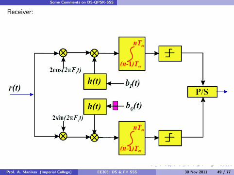
DS-QPSK-SSS implementation No.1: QPSK1
(Note: if = Tc2 delay is inserted then OQPSK1 - o§set QPSK1)
Transmitter:
s(t) =p2Ps · cos(2πFc t +
tan!1(bQ (t)·mQ (t)bI (t)·mI (t)
)
z}|{ψ(t) )
Prof. A. Manikas (Imperial College) EE303: DS & FH SSS 30 Nov 2011 48 / 77
Some Comments on DS-QPSK-SSS
Receiver:
Prof. A. Manikas (Imperial College) EE303: DS & FH SSS 30 Nov 2011 49 / 77

Some Comments on DS-QPSK-SSS
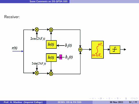
DS-QPSK-SSS implementation No.2: QPSK2
(Note: if = Tc2 delay is inserted then OQPSK2)
Transmitter:
s(t) =p2Ps · cos(2πFc t +
tan!1(bQ (t)·m(t)bI (t)·m(t)
)
z}|{ψ(t) )
Prof. A. Manikas (Imperial College) EE303: DS & FH SSS 30 Nov 2011 50 / 77
Some Comments on DS-QPSK-SSS
Receiver:
Prof. A. Manikas (Imperial College) EE303: DS & FH SSS 30 Nov 2011 51 / 77

Frequency Hopping SSSs
Frequency Hopping SSSs
Consider that the following part of the spectrum has been allocatedto a FH/SSS:
Let us partition the above spectrum onto L di§erent frequency slotsof bandwidth F1 (or of bandwidth qF1 where q is a constant). ThenBss = q · F1 · L
L = 2m
Prof. A. Manikas (Imperial College) EE303: DS & FH SSS 30 Nov 2011 52 / 77
Frequency Hopping SSSs
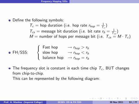
Define the following symbols:Tc = hop duration (i.e. hop rate rhop = 1
Tc)
Tcs = message bit duration (i.e. bit rate rb = 1Tcs)
M = number of hops per message bit (i.e. Tcs = M · Tc )
FH/SSS:
8<
:
Fast hop ! rhop > rbslow hop ! rhop < rbbalance hop ! rhop = rb
The frequency slot is constant in each time chip Tc , BUT changesfrom chip-to-chip.This can be represented by the following diagram:
Prof. A. Manikas (Imperial College) EE303: DS & FH SSS 30 Nov 2011 53 / 77

Frequency Hopping SSSs
In general, the No. of di§erent frequency slots L over which the signalmay hop, is a power of 2.
Prof. A. Manikas (Imperial College) EE303: DS & FH SSS 30 Nov 2011 54 / 77

Frequency Hopping SSSs
F1 is, in general, equal to 1Tc,
i.e. F1 = 1Tc(but this is not a necessary requirement).
several FH signals occupy a common RF channel
FH model of b(t) - (complex representation):
b(t) = ∑nexp {j(2π.k [n].F1t + φn)} · rect
*t ! nTcTc
<
where
I k [n] =f{PN-sequ {α[n]}}I k [n] is an integer that is formed by a codeword which is formed by oneor more m-sequences
Prof. A. Manikas (Imperial College) EE303: DS & FH SSS 30 Nov 2011 55 / 77

Frequency Hopping SSSs
Transmitter-Receiver path:
Prof. A. Manikas (Imperial College) EE303: DS & FH SSS 30 Nov 2011 56 / 77

Frequency Hopping SSSs
A Di§erent Implementation:
Prof. A. Manikas (Imperial College) EE303: DS & FH SSS 30 Nov 2011 57 / 77

Frequency Hopping SSSs
L frequencies are produced by the digital Frequ. Synthesizer,separated by F1
Bs ' q · F1 · L (43)
Note:I if reception= coherent :
F more di¢cult to achieveF places constraints on the transmitted signal and transmitted medium
I if reception= non-coherent :
F PN-gen. can run at a considerably slower rate in this type of systemthan in a DS system
Prof. A. Manikas (Imperial College) EE303: DS & FH SSS 30 Nov 2011 58 / 77

Frequency Hopping SSSs
FH: non-coherent ) poorer performance against thermal noise.
Performance:I Coherent FSK (CFSK)
pe ,CFSK = Tnp
EUEo
I Non-Coherent FSK (NFSK)
pe ,NFSK =12exp
(!EUE2
)
Prof. A. Manikas (Imperial College) EE303: DS & FH SSS 30 Nov 2011 59 / 77
Frequency Hopping SSSs
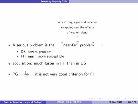
A serious problem is the
very strong signals at receiver
swapping out the e§ects
of weaker signal
*z }| {“near-far” problem :
I DS: severe problemI FH: much more susceptible
acquisition: much faster in FH than in DS
PG = BssB = it is not very good criterion for FH
Prof. A. Manikas (Imperial College) EE303: DS & FH SSS 30 Nov 2011 60 / 77

AppendicesAppendix A. Block Diagram of a Typical Spread Spectrum
System
AppendicesAppendix A. Block Diagram of a Typical SSS
(terrestrial & satellite comm. systems)
Prof. A. Manikas (Imperial College) EE303: DS & FH SSS 30 Nov 2011 61 / 77
Appendices Appendix B. BPSK/DS/SS Transmitter and Receiver
Appendix B. BPSK/DS/SS Transmitter and ReceiverBPSK/DS/SS Transmitter
Prof. A. Manikas (Imperial College) EE303: DS & FH SSS 30 Nov 2011 62 / 77

Appendices Appendix B. BPSK/DS/SS Transmitter and Receiver
BPSK/DS/SS Receiver
Prof. A. Manikas (Imperial College) EE303: DS & FH SSS 30 Nov 2011 63 / 77

Appendices Appendix C. QPSK/DS/SS Transmitter and Receiver
Appendix C. QPSK/DS/SS Transmitter and Receiver
Transmitter
Prof. A. Manikas (Imperial College) EE303: DS & FH SSS 30 Nov 2011 64 / 77

Appendices Appendix C. QPSK/DS/SS Transmitter and Receiver
Prof. A. Manikas (Imperial College) EE303: DS & FH SSS 30 Nov 2011 65 / 77

Appendices Appendix C. QPSK/DS/SS Transmitter and Receiver
Receiver:
Prof. A. Manikas (Imperial College) EE303: DS & FH SSS 30 Nov 2011 66 / 77

Appendices Appendix D. Proof of SNIRout (Equation 27)
Appendix D. Proof of SNIRout (Equation 27)
Prof. A. Manikas (Imperial College) EE303: DS & FH SSS 30 Nov 2011 67 / 77

Appendices Appendix D. Proof of SNIRout (Equation 27)
N.B.: Bss = 1Tc; B = 1
Tcs; PG = Bss
B = TcsTc
Then at point T1 we have
s(t) = Ac ·m(t) · b(t) · cos(2πFc t) (44)
and at point^T1 :
s(t) + n(t) + j(t) (for k = 1) (45)
At the input of the receiver the Signal-to-Noise-plus-InterferenceRatio (SNIRin) is:
SNIRin = PsPn+Pj
= Ps/Pn1+Pj/Pn
=Ps ·Tcs
N0 ·Bss ·Tcs1+JNRin
=EUE
Bss ·Tcs1+JNRin
= EUEPG·(1+JNRin)
Prof. A. Manikas (Imperial College) EE303: DS & FH SSS 30 Nov 2011 68 / 77

Appendices Appendix D. Proof of SNIRout (Equation 27)
i.e.
8><
>:
SNIRin = PsPn+Pj
EUEPG·(1+JNRin)
or
SNIRin =A2c/2
N0 ·Bss+Pj
(46)
However,
EUEequ =Eb
No +Nj=
Eb/N01+ Pj
BssN0
=EUE
1+ PjPn
=EUE
1+ JNRin(47)
Therefore,
SNIRin =EUE
PG · (1+ JNRin)=EUEequPG
(48)
Prof. A. Manikas (Imperial College) EE303: DS & FH SSS 30 Nov 2011 69 / 77

Appendices Appendix D. Proof of SNIRout (Equation 27)
at point^T :
(s(t) + n(t) + j(t)) · b(t ! τ) · 2 cos(2πFc t + θ) (49)
at point T0 :
i) signal term:
m0(t) =AcTcs
·Z Tcs
0m(t) · b(t) · b(t ! τ) · cos(θ) · dt
= ±AcTcs
· cos(θ) ·Z MTc
0b(t) · b(t ! τ) · dt
) m0(t) = ±Ac · RMbb(τ) · cos(θ) (50)
Prof. A. Manikas (Imperial College) EE303: DS & FH SSS 30 Nov 2011 70 / 77

Appendices Appendix D. Proof of SNIRout (Equation 27)
However,
Pm0 = E:m20(t)
;= A2c · E
nRM
2
bb (τ)o· cos2(θ)
+
Pm0 = A2c ·=Var
nRMbb(τ)
o+ E2
nRMbb(τ)
o>· cos2(θ)
=) Pm0 = A2c · Var
nRMbb(τ)
o· cos2(θ)
"due to Code Noise
+ A2c · E2nRMbb(τ)
o· cos2(θ)
"desired term
(51)
Prof. A. Manikas (Imperial College) EE303: DS & FH SSS 30 Nov 2011 71 / 77

Appendices Appendix D. Proof of SNIRout (Equation 27)
However:
E {m0(t)} =
8<
:
±Ac · E:RMbb(τ)
;· cos(θ) for |τ| ' Tc
0 for |τ| > Tc
333333(52)
i.e.power of
desired signal part= Pdesired = E2 {m0(t)} (53)
=
8><
>:
A2c ·Λ2=
τTc
>· cos2(θ) for |τ| ' Tc
0 for |τ| > Tc
3333333
Prof. A. Manikas (Imperial College) EE303: DS & FH SSS 30 Nov 2011 72 / 77

Appendices Appendix D. Proof of SNIRout (Equation 27)
In addition
Var {m0(t)} = Varn±AcRMbb(τ) cos(θ)
o
= A2cVarnRMbb(τ)
ocos2(θ)
) Pcode-noise = Var {m0(t)}
if 0 ' τ ' Tc then
Var {m0(t)} = A2cVarnRMbb(τ)
ocos2(θ)
= A2cR2cc (τ ! Tc )M · T 2c
cos2(θ)
=A2cTcTcs
τ2
T 2ccos2(θ) (54)
if τ > Tc then
Var {m0(t)} = A2cVarnRMbb(τ)
ocos2(θ)
= A2c1Mcos2(θ)
=A2cTcTcs
cos2(θ) (55)
Prof. A. Manikas (Imperial College) EE303: DS & FH SSS 30 Nov 2011 73 / 77
Appendices Appendix D. Proof of SNIRout (Equation 27)
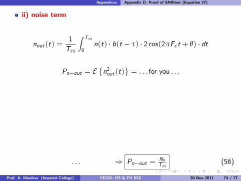
ii) noise term
nout (t) =1Tcs
Z Tcs
0n(t) · b(t ! τ) · 2 cos(2πFc t + θ) · dt
Pn!out = E:n2out (t)
;= . . . for you . . .
. . . ) Pn!out = N0Tcs
(56)
Prof. A. Manikas (Imperial College) EE303: DS & FH SSS 30 Nov 2011 74 / 77

Appendices Appendix D. Proof of SNIRout (Equation 27)
iii) jammer
If Bj 5 Bssthen Jammer = Narrowband wrt the desired SS-Signal.
In this case the jammer j(t) can be modelled as:
j(t) = Aj (t) · cos(2πFj t + φj (t))
and the jout (t) can be estimated as follows:
jout (t) =1Tcs
Z Tcs
0j(t) · b(t ! τ) · 2 cos(2πF0t + θ) · dt
= for you . . .Prof. A. Manikas (Imperial College) EE303: DS & FH SSS 30 Nov 2011 75 / 77

Appendices Appendix D. Proof of SNIRout (Equation 27)
for you . . .
) Pjout =PjPG (57)
N.B.: If jammer = wideband, i.e. if Bj 6 Bss , then Pjout = ?
Prof. A. Manikas (Imperial College) EE303: DS & FH SSS 30 Nov 2011 76 / 77

Appendices Appendix D. Proof of SNIRout (Equation 27)
From the previous analysis we have
Punwanted =
8><
>:
N0Tcs+ A2c
Tcs ·Tc · τ2 · cos2(θ) + Pjout for |τ| ' Tc
N0Tcs+ A2c ·Tc
Tcs· cos2(θ) + Pjout for |τ| > Tc
3333333(58)
Therefore
SNIRout =PdesiredPunwanted
=
8>><
>>:
A2c ·Λ2( τTc )·cos
2(θ)
N0Tcs+ A2cTcs ·Tc ·τ
2 ·cos2(θ)+Pjoutfor |τ| ' Tc
0 for |τ| > Tc
33333333(59)
Prof. A. Manikas (Imperial College) EE303: DS & FH SSS 30 Nov 2011 77 / 77