principles of direct current resistivity prospecting
TRANSCRIPT

5/13/2018 Principles of Direct Current Resistivity Prospecting - slidepdf.com
http://slidepdf.com/reader/full/principles-of-direct-current-resistivity-prospecting
ffiUNAMIiltiltiltililtilIilililtililililil
FACULTAD DE INGENIERíA

5/13/2018 Principles of Direct Current Resistivity Prospecting - slidepdf.com
http://slidepdf.com/reader/full/principles-of-direct-current-resistivity-prospecting
?u-¿;ts tr.ü,it.'<4. Al4 4 qL|;¡.*.tat6t.h'r/* (atvuV ). *-irL' 4'L4tú ryt 2-
1¿-t---.L"-/E¿L&, , t
,-r, Fa(-
Aa¿'\ aGt¿.fá.¿'*
t¿'
¡!'I
,4;t
lr---
lE ¿, t+; u l't|t-u . r* .1Le.' e 1# l¿t\¿L 1-¿ u. ¿ku i.¿* n-t a44-f b ¿. 4.4 4.Jú;+*) tt ú aLl' ¡¿q^ t ia-s.*2¿¿n* a44-f b ¿. Lá 4AJú;U') tt ú aL'L t'¿*a | ¿4A.4-uq Ca L** ¿t f/..¿4 4 4 ú¿. b.4. 4fr;+a'la, *t.:^-r1.:^. t- ¿¿b ta ¿ 1 ?t.-t4;;- . i.¿A- &, -.U- ,:r 1,¿'z^ -.¿: - n4t8. lt ú¿/ta /.at ¿ 1 ?l-,ai;L , i,t;A- z- -*- 7ir /,t'4 t ¡: ú u4.tt;TÉ;*a,;t *.4/*. a u-1s.z-f, ¡7.!¿úa aFb*--a^ ? +¿.!¿L--: h*t¡.¿t-4&'-eLL,t ¿: !"4 !4:.n ,
T.;Í.;a-- t'4.:)i.bú- ,-t-Ji -i;r-,,;ú42J2*-..4rtl i ..--¿ t.-4ri-- ¡I uz^ L h *^tA-L 4¿* f L-. 4.tu+4 -rú-4./. ,L--t !,,e ?rú)M &Llú. ¿. Le *^:^'L. a¿* IL-. a,^/u ¿)¿--a./. ,i--t^',e grú)e a¿lu¿LílI¿;L..-á..11F-/*-. ¿&q*/. tt'r-r'¡.t: A.1.Lú 1' ¿.tb'rt-4.J¿.'9ú'-rt! e..,J
.-- ¡ ^c*irrut¡^L¿,¿ A4 .LJ:u** t- r'. - Lj.'fr: ftL-L-L'añ.- LL-ñte +/Ep|
i, \
/Á\,/,
\
\,,, \-/ \ t
-,\l
t\ttl
i{
a\'\
\
_\- r-
I
iI
II
n/
w L-:ú,-#
111 l^at¿tu-:^ 9¿- 5 ¿+ L:¿=':ii js¡!t1,1 t**2. - ^t;-. ;-t-Ea-taP* 4.-¿¿a1É(a.4/.&x4-. Fr¿;+lü'-:¿t.42/-ú fÉ¿..¿ hr! (t¿¿ a-,La,,ú
--*uá;-.t,!pi-¿ i-^.-*fu,¿*. zE_l^ lj.-_LL.ar¿.¡!t1 t Fb tu .- e .iL-, cl.tya,¿. íl->a 4*¿.¿
4a-eí*r..É.L._avaa¿ titlfu-.-.a*- q@. ,¿b1 L-. a É
=a*-b-r-*r*t4
- ^-¿*ib áf,-lc. . 7 C. I
-rl>a,tA
'q' ¿r.+1;'l¿.t'¿'r4. ¿^tEEt
&l¿- ,?'*aU^¿rr*7r-*¿a;-/'-> b.u ¡L-ú|,¿l¿ A.¡- * u.&¡1f+./ ..4 ¡,lí;tr'*É-:rs tÉ,áf
;" Ú-s "'- ¿+t!4;'-a¡L &Ia.¡l.¡: ¡r¡ -'L . -.
II
I
;=. . .' " l-J,, iqp i t t1'* ,/'t-i:¿ tt-.L tTJ h^ ts.. tt ¡..*- ,;- eliló^*'''*d +ú;2-^ *4Et *4 ¿*1,*l'4.r..-.Á'r,¿ 4 L.a útt|r'urb 4-Á.h,+:aé,¿,.'*t -:*i - a.*t-i/i..\tP4.4l-: -- ^(,És- ttt';.t -
'p.^'.;.-+4 -12*.te.**!1.>
'*d +ú;2-^ *4Et *4 ¿*1,41'4.r..-.5'r,¿ 4,b.4 útt|r'urb LaÁ.h,+:aé,¿,.'*, -'*i - a.*t-i/i..\'-' .-1.41.: -- ^l/ús- lr4;t -1^'1e. ^'É;>xl-L¿';4
ak.A r?.rF4rV-1,íÁ t*.r'l- a..# t¡-'t-\ ,, ¿4 4
^¡^-:!"Ctu444' '4= ü+-+6_:1¿'-t-.. 7L4
^::; ;.* u*--*,tDJ4¡ai *,q¡-.1^* (.F:*a++vt),rbtu uL*1/u'¡{É )ty';c4' b-.7, . ). ^¿L- /.* r^ );.--;^^ d. A a¿6.1¿*- 4 aF, 't '4 ... 4hH, ,b-'lLt^ ,¿oü-.r¿.-¿..---¡'ii i I -;-;;"rc.- .'1:# T :! t' :t f : :tf f-* o!/ ;.1':- :* 'fr".:.;t-.f-r,*'aJ71,t;L 4;siAr¿ 4/¿t4*a h¡..;-lt4-.nl;11'-'¿1 'a¿e'
ú'ú/4'^,-.;, ,¿lúLr+)&_._¡ .ú ,.4 4Ft¿.J-llrilfJÉi¿**, ¿a.b' laa 4/4*¡ . '
'*7u.-' *' ¿. L¿ti. L ¡t ¿i¿t-'¿'!'.'' /'-a-a. (aF¿a., L'.¿^ ). Da¿ : -^l , 6 ú¿L-a hL.^4i¿. t-'t¿i-*'¿4 t-; u'a&,. tL--.J4 *J|--'
*' ¿. L¡si L hl úy'.¿\-'.['-' - /-a-a, (aF¿a ¿ ld¿^ ). Da 4 tlL:eúki4 L Jd¡4*) qaú?' h.-.^ü.L P¿'--,a'¿úd u'a*. L-.J4L..- ,^AFa
-JiJ-
&&ú.*,h^
lev¿¿ls e¿¿, G¿ptúau->PfÁ)
*J*u u /o¿ tl 4.4 4 Lv1 -L!-:^. ^¿ - :;,7; : ffi+Y-i% i' #."'*: aa* *:;n 1: !, ? ! ;& ;' i"ffi frzffiw Lt:,-# ffi *¿4:.-,*: ;7::::;,4: ;" ;;: ;# .*f '*:'# ffir: frt' *,''-¡ *;dr'ilíl^J o* 1d /É ,--¿).

5/13/2018 Principles of Direct Current Resistivity Prospecting - slidepdf.com
http://slidepdf.com/reader/full/principles-of-direct-current-resistivity-prospecting
$g. :1. l)quipotential map, resulting fromUoNRAD ScEr.uMBEncF-R's fint experimentsin Val-Richer (Calvadoe) in l9l2
)
h.¿t--*si.sErt'-rta r-.a,Li¡ñ'- +/J¿,,- r,,!¡tsa--dL,'l'*t
#'\--/r,-tJ-i ¿¡'''.- tFtr-lLHrJ-a¿[L-a-_ t¡É- ¡rúa l-r+-.¿, &-i !ta-.r,ril-'¿. ,¡L--a- ---á-.i-! At'4.l -+j'&-.1rt1;*-5-\ 1ú*;;,.L- ¿trb,p.-*,Ji¡¡¡,
r¡fr.r** a-.*)4.:'-,#+-e*tu<L
=.4q..éf,_É:ñí-aü{-¡¡ .aAi+.h-, *i-
ll
ii[!\;\.
{f
ilrJJT{;i{ill{ti ii'{l¡I ¡{arC{
ilt"l{{t*J.tl¡: {ii
ij\ii
\\
\
\
Ct* -ü'

5/13/2018 Principles of Direct Current Resistivity Prospecting - slidepdf.com
http://slidepdf.com/reader/full/principles-of-direct-current-resistivity-prospecting
GE OEXPLORATIOI{ }IONO GRAPH S
Series 1-No. I

5/13/2018 Principles of Direct Current Resistivity Prospecting - slidepdf.com
http://slidepdf.com/reader/full/principles-of-direct-current-resistivity-prospecting
G u opu BLrcATro N A s s ocIATE s
GE OEXPLORATI ON MON O GRAPIIS
Series 1-No. I
EditorsH. Bnluxr¡rv Trondheim/NorwaY
R,. veN Nosrn¿no Alexandria/Virginia USA
1966
GEBR,ÜDER, BOR,NTR,AEGER, BER,LIN-NII{OLASSEE

5/13/2018 Principles of Direct Current Resistivity Prospecting - slidepdf.com
http://slidepdf.com/reader/full/principles-of-direct-current-resistivity-prospecting
Principles of Direct Current
Resistivity Prospectingby
GEZA KUNETZ
Ifead of the Department of Theoretical Research
Compagnie Générale de Géophysique-Paris
1966
üNen BoR,I{TR,AEGER, BERI,IN-NIKoLASSEE

5/13/2018 Principles of Direct Current Resistivity Prospecting - slidepdf.com
http://slidepdf.com/reader/full/principles-of-direct-current-resistivity-prospecting
Translation from the French by Roront VeN NostneNo,
Manager of Research, Earúh Sciences Division,
Teledyne Industries, Alexandria, Virginia/U. S.A.
'rÍ{,\'"
,tsru u fio$üHt¡
All rights reserved, included those o{ translation or to reproduce parts of this book in any form.
Cop¡'right @ 1966 by Gebrüder Borntraeger, I Berlin 38 (Nikolassee)
Printed in Germany by Langenscheidt KG, I Berlin 62 (Schóneberg)
Blocks: Dr. S. Toeche-Mittler, I Berlin 6lPaper: Scheufelen KG, 7311 Oberlenningen
Type: Borgis Exüended

5/13/2018 Principles of Direct Current Resistivity Prospecting - slidepdf.com
http://slidepdf.com/reader/full/principles-of-direct-current-resistivity-prospecting
It
Table ol Contents
T.ist' of Illustration . VIIEr¡ata . .IXP¡esentation .XIForeword
C'hapter f. fntroduction .
1 llistory
2. Rock Resistivities.3. Potential Distribution in the
-1. Alternating Currents5. Exploration Principles and Proc'edures
a
XII
II15
8
I
24242429
2931
35
rfu
4343
48
Earth
Chapter II.I. General
Equipotential Maps T2
l2r3t823
2. The Effect of Heterogeneities3. The Effect of Anisotropy .
-1. Conclusions
Chapter fII. Resistivity Profile and Mapsl. General2. Configurations3. Methods of Apptication3a. Horizontal Profiling .
3b. The Rectangle Method3c. Presentation of Results1. Effect of Various Structures4a. AB Rectangle4b. Horizontal Profiling .
5. Conclusions
. \' ct,, j . ."'. tr+'.-rt^ad!rtl
G Lfr?ñL"*^-**#r¡f

5/13/2018 Principles of Direct Current Resistivity Prospecting - slidepdf.com
http://slidepdf.com/reader/full/principles-of-direct-current-resistivity-prospecting
VI
Chapters0
1.505l
31
3: ii. Stucly of Horizontal Stratification .
3a. Relation between the Resistivityli**i¡*ioo rrra in" u""*i*r so";dúuu
Curve . I sl3b.Theoretical Electrical sounüng co"o"*, ..-p"i"a by'exact,Methods . 6r3c. Catalogues of Theoretical Curves 633d.Approximate Construction of Electrical Sounüng Curves 6b4. The Efiects of Other Structures 7l4a. Dipping Contacts ?l4b. Vertical Contacts4c. Other Structures 77,5. Interpretation of Electrical Soundings gb
Appendix 9ll. Determination of the potential Distribution in a Layered Meüum gr2. Practical Calculation of Apparent Resjstivities 93
iil#ll*l$:iB"J:il"_ftt"; : . 3l2c. Method of Numerical Integration 97
References . f00Index. . lo2

5/13/2018 Principles of Direct Current Resistivity Prospecting - slidepdf.com
http://slidepdf.com/reader/full/principles-of-direct-current-resistivity-prospecting
I
List of Illustrations
Page
:=. t. Equipotentials and cunent lines in a homogeneous earlh 6
l:. l. B,efraction of current, Iines where they cross a bounclary between two media of different resistivities 7
a:. 3. EElipqtential-m1p, _resulting from Coxn¡o Sculurrsnne¡n's first experiments
in ValRicher (Calvados) in lgl2 paste-down
f=. +. F,esults of experiments near Sassy (Calvaclos) in 1812 paste-down
l':. 5. Effect of buried inhomogeneities on equipotentials and current lines at the earth's
surface lBf=. 6. Uniform current flowing through an earth containing a buried" sphere 14
-;. 7a. Equipot'ential lines about a point source at' úhe earth's surface near a verlicalcontact between two media 16
a:1.;b. Equipotential lines about a point source at fhe earth's surface near an inclinedcontact between two media 17
.=. S. Equipotential and current lines, at the earth's surface, due to a unilorm currentcrossing a contact between two meilia lb
a=. 9. Effect of topography in a homogeneous earth 18
F;. 10. Effect of topography in an inhomogeneous earth lgI'r.11. Construction required to determine p¿ in an anisotropic medium using the
- principle of compressionl¡. 12. Current electrode buried in a üpping, anisotropic medium 22
Iil. 13. Various configurations 2E
lil. 1.5. Three independent quadripole configurations 27
l-i:. 16. Determination of the geometric factor K . 28
lil. 17. Presentation of results corresponding to configuration displacements as shown 29
fl¡. 18. Profiles ancl rectangle AB Z2
:rl. 19. Profrles across rectangle AB over a resistant anticline 86
a€.:0. Effect of a buried, perfectly conducting pipe 87
5/13/2018 Principles of Direct Current Resistivity Prospecting - slidepdf.com
http://slidepdf.com/reader/full/principles-of-direct-current-resistivity-prospecting
VIII List of Illustrations
Fig. 21a. Effect of some cylindrica,l structures on a uniform fieldtr'ig. 2lb. Effect of some cylindrical structures on a uni{orm field .
Fig. 22. Il,esistivity profile over a vertical contact ancl a dipping contact
Fig. 23a. Comparison of the influence of cvlindrical structures and domes of the samediameter when the current, electrodes are far removealFig. 23b. Yariation in the maximum relief in the field as a function of the height of a
cylindrical structure or a dome, when the diameter equals the depth to iis top .
Fig.24. Effect on a uniform field of an eroded. anticline and synclineFig. 25. Images formed when a current electrode is near ¿, vertical contact between two
media
l'ig. 26. I{orizontal profiIes over a vertical contactFig.27. Resistivity profile perpen{lggtar to a vertical concluctive bed of thickness AB/2,
with infnitesimally small MN .
fig.28. Electrode effect in holizontal profrling over semi-circular, cylindrical and hemi-
spherical inhomogeneities of thé same áiameterFig.29. Yariation of t'he apparent resistivity due to vertical contacts in the sub-stratumand the overburden
Fig. 30. rncrease in depth of penetration with increasing electrode separationsFig. 3L CoTparisorr of electrode effects due to MN for the Schlumberger ancl \{¡enner
configurations
Fig. 32. Advantages of drawing resistivity profiles to a bilogarithmic scalel'ig. 33. Joining the branches o{ the resistivity curve for increasingly larger }rN'sFig. 34. 9oyp-arison of-resistivity profiIes over horizontal beds and over slightly dipping
beds far from the surfacé tiace of the contact!-ig. 35. Principle of equivalence and
its limitsFig. 36. Principle of suppression
Fig. 37. Comparison ol the apparent resistivity and Dar-Zarrouk curvesl'ig. 38. Nlethod of development' in an infinite series to compute the potentialfig. 39. Various forms taken on by apparent resistivity
"oro".Fig. 40a. Three-layer apparent resistivity curves. variable thickness of second layerFig. 40b. Three-layer apparent resistivity curyes. Resistivity of second layer variableFig. 40c. Fo'r-la,yer apparent resistivity curves. ri,esistivity of thircl layer variableFig. 41. Approximate construction of apparent resistivity curves ..
Fig. 42. Graphical construction of approximate resistivity curves
Fig.43. Effect of a thin, conductive overburden over a resistant upper layer in thetwo-layer case
Fig.44' Comparison belween resislivity. profiIes made wilh a configuration parallel to adipping contact, and over a hoiizontal bed . : . .
Fig. 45. {pPa,rent resistivity curves made with a configuration normal to the strike of adipping contact
.tI
42
43
41
45
46
50
Pagc
38
39
10
4I
54
55
56
5960
6t62
64
65
66
tl/
68
69
70
72
'i4Fig. 46. Comparison of r-esisbivity curves made with the configuration parallel to the strike
of a dipping bed and ov-er horizontal beds 7EFig.47. Electrical soundings near a veriical fault over an infinitely ¡esistant, sub-
76tratum

5/13/2018 Principles of Direct Current Resistivity Prospecting - slidepdf.com
http://slidepdf.com/reader/full/principles-of-direct-current-resistivity-prospecting
II
List of Illust¡ations IX
PageFig' 48' Electrical soundings near a vertical contact underlain by an infnitely resistantsub-stratum i7
Fig' 49' Electrical soundings near a thin vertical dike u¡derlain by an infinitely resistantsub-stratumF8.50.
F€.51.
Fig. 52.
F9.53.I rq, D4.
-tr"- 05-
rr-s. ob.
tt!. a L
rq.;s.
Errata
Fase 14 Fig. 6 on the drawing the angle $ should be at point M.¡age 62 tr'ig. 38 instead of faktor, read factorrage 90 Fig. 57 the "box', relaúive to curve @ should read l_Ig_2 _ll4_ x
(instead of l-99-2-t/a- o)
Electrical soundings near a vertical fault, upiifting an infinitely resistant sub-stratum79
Electrical sounding -over a horst of infinite resistivity, with the configuratio'parallel to the axis of the horst g0comparison of resistivity curves made with configurations paralrer to, andnormal to, infiritely resistant horsts, as measured on sóaled mocle'ls . . :"1 . . tt2Elecórical sounding over a cylindrical outcrop g3
Electrical sounding with configuration parallel to a buried conductive pipe g4Resistivity curves with simple forms noú compatible with two-layer or three-layer
problems g7Determination of transverse resistances anc{ horizontal conductances . .,. . gg
R,esistivity curves for six layers alternatively resist¿r,nt and conductive g0
construction of an electrical sounding curve by the method of decomposition 96

5/13/2018 Principles of Direct Current Resistivity Prospecting - slidepdf.com
http://slidepdf.com/reader/full/principles-of-direct-current-resistivity-prospecting
To the memory ofCoNnao S cnr,ulrenR,c DR,
( r878 - te36)

5/13/2018 Principles of Direct Current Resistivity Prospecting - slidepdf.com
http://slidepdf.com/reader/full/principles-of-direct-current-resistivity-prospecting
Presentation
Scur'u¡¡nnnenn's early work in direct current prospecting \4¡as one of the mainstays¡f the evolution of geoexploration techniques.Thus, it seems most appropriate that Diect current Resistivity Methods by GnzaKrxrrz has become the first issue of the GEOEXPLORATTóN MoNoGRApH
SERTES; the author has been a long time conaborator of scnr,uMennsnn and theLbmpagnie Générale de Géophysique.
.rt may also readily be admitted that d.ue attention has probably not been paid tothe merits of these classical I{rench developments in the further evolution of geo-
electrics, probablv not in mining geoelectris anel certainly not in prospecting fordeep structwes. we have recentr¡r looked anew at the earry rrench monograph: theEtude sur la Prospection Electrique du sous-sol,, writien by coNnao sc¡rr,u.r_EER*ER in 1920. rt shoutd still be read. by aI prospective exploration geophysicists.\\'Iith the ever-increasing wealth of information stored inJne fires of progressiveorganizations, or described in internal literature, Iike the present monograph, it isabsolutel¡' necessary to a healthy development of the science ihut u, r"u*orrable amountof such information be made accessible to future students. I{ow can they otherwise¡ome to have a souncl conception of exploration geophysics ?
The Compagnie Générale de Géophysique anclits Chairman Mn. L. Mrc¡.ux deservethe
praise of everybody interesfudln'our science for consenting to the p'blication ofthis i¡ono",unt text from its private library. This first releuse.-of an internal treatisedoes indeed mark a timely maturing of the profession. It will benefit all concerned.¿nd' we hope will be folrowed by corresponding rereases from other organizations.
I[. Bn¿.mxnr.¡ R,. VaN lr[osrna¡¡o

5/13/2018 Principles of Direct Current Resistivity Prospecting - slidepdf.com
http://slidepdf.com/reader/full/principles-of-direct-current-resistivity-prospecting
I
tr'oreworil
Ou aim is to give a general but elementary treatiso on the principles of electricalr'rospecting with direct current resistivity methods. Thus we h#e voluntarily limited:,urselves to:r- un oaerall aietn, for none of the subjects wil be treated furly!- tririnciples, for neither the apparatus used nor the methods of making measurements
and of computing will be includ,ed, nor wil any practical results bo discussed3'" direct current, for the methods of alternating currents warrant special treatment,
and+- ro-'sístiu'ity me'thoils,for the other methods such as self potential, induced polarizationand telluric current will not be treated.llter an introduction which begins with a brief history and a general view of the
srbject, tbree chapters deal successively with potential maps, resilstivity profiles and*aps- and electrical soundings. rn each of the chapters ihere is first a review of-"1-: generalities, then an examination of the methods oi application, and finally, a look*'; the principles of interpretation. This latter term is taken in a restricted. sense ancl--i¡-rs to the influence of various structures on the measurements.
' The mrmerous figures that illustrate the examples are, however,not schematic butn'¡,¡st all of them represent exact curves obtained by computation or by measure-
-:nts on small-scale models. They compensate, to a certain &tent, for thelecessarilyl-:a5tative discussions in the text. A few formulae and. numerical results have beenn'if,r'f, to the same effect' Moreoyer, some mathematics on the methocLs of calculation:c :heoretical curves are given in an Appendix.
The list of references, which is to be iound at the end of the text does not claim:: io complete.T[e hare thus tried to give a general survey, illustratecL by examples, of the various; ':-'t'fures in use' makingpossible a comparison of their advuntug"ünd disadvantages
n- i an appreciation of their possibilitiesand their limitationi. This work shoofd,¡;:'-;e all. awaken arr interest in the problems that are set by direct current resistivity

5/13/2018 Principles of Direct Current Resistivity Prospecting - slidepdf.com
http://slidepdf.com/reader/full/principles-of-direct-current-resistivity-prospecting
XVI Foreword
prospecting, and serve as an introduction to a treatise d'evoted to a more thorough
stud,y of the numerous facets óf electrical prospecting'
This text was originally written for an internal Manual of the compagnie Générale
d.e Géophysiqo";
"oo*"qo"ntly,
much of the material has been drawn from previous
internJ publications. TL" uothot therefore wishes to thank all his colleagues whosetheoretical and practical experience forms the basis of this book, and. above all Mr
L on M¡c-lux, Chairman of the Company, who, in addition, has allowed publication.
He also expresses his gratitude to Dr. R,osnnr V¿r Nosrnalto whose generous
and boundless efforts of translation and revision have resulted in this English version
of the text'G. Ku*utz

5/13/2018 Principles of Direct Current Resistivity Prospecting - slidepdf.com
http://slidepdf.com/reader/full/principles-of-direct-current-resistivity-prospecting
CzuPTER I
INTR,ODUCTION
I.1 History-\s in the rest of this work, we shall give but an outline of the historical develópment
',f electrical prospecting.Birth of Electrical Prospect'ing. For practical purposes, electrical prospecting
rriginated during the summer of 1912. During the school vacation of that year,t- oxnao Scnr,u¡rnnnenn, senior mining engineer and then professor of physics at:he Paris School of Mines, perfected the technique. 'Ihe procedure was the fruit of a-rng period of thinking, after which he chose his equipment and conducted. the first:-rper.iments in the fields of Normandie.
Several attempts before this time remained without a follow-up because they werei,rulded upon more or less erroneous principles. Some persons had tried to use alter-rating curtent whose frequency was so high that it could not penetrate the earth.q-thers used direct current but were content to measure the resistance offerecl" by the=arth to a current flowing between two electrodes, a resistance which depends practi-,a1lr only upon the material immediately adjacent to the electrodes. We point out,-aorFever, that later alternating currents with properly chosen frequencies have:'=n.-lered. excellent results, particularly in mining exploration in crystalline rocks.
Ear|y workers. rt seems equitable, even thougb it is not our purpose to give a-rrmplete history of electrical prospecting, to note rapidly some of the workers who-an justly be consid.ered to be fore-runners of CoNnep Scur,ulrsnnenn*. Although-re Englishmen, GRAy, wrrn¡r,nn and W¿rsox, near the middle of the lSth century,::terested themselves in the electrical properties of rocks and. measured their con-rur'tirity, the first important work in electrical prospecting must be attributed tor -,s (1789-1877), who, through his knowledge of geology and his studies of the:orrperature of the earth, electricify, and terrestrial magnetism, merits being con--ierecl the grandfather of geophysicists. fn the mines of Cornwall, he observed. the:-' iitence of natural electric currents that he attributed to deposits of metallic sulficLes.h 1333, he constructecl the first potentiometer using the bridge principle. In partic-* ]i:.s Nosrn¡.rvl & Coor, Interpretation of Resistivity Data, U.S.G.S., Professional Paper (in
- ;::É\plor¿tion 1,1

5/13/2018 Principles of Direct Current Resistivity Prospecting - slidepdf.com
http://slidepdf.com/reader/full/principles-of-direct-current-resistivity-prospecting
fntroducüion
ular, we find in his papers that he made the following prophetic statement: ,,rt seemslikely that electromagnetism may become useful to the practical miner in determining,to some degree of probability at least, the relative quantity of ore in veins and th1direction in which it most abounds."
Although Fox'was the inventor of the phenomenon that Cown¿n Scrrr,u¡nnnnenn'was later to call "self-potential" (Polarisation Spontanée), Marrnuccr, of the Green_wich Observatory, was the first to have observed the existence of telluric currentsand their correlation with the aruora borealis (1865). The first potential map wasprepared by C. ScnT,uMBERGER in 1gt8 on the pyrite deposits of Sain-Bel (Rñone).
rn America, Ben¡rns (1880), BnowN (1891) and wnr,r,s (lgl4), all members of theU.S. Geological Survey, studied self potential phenomena in mines in l[evada, an¿developed the first non-polarizing electrodes. It is interesting to note that the firstof these, working a half-century after x'ox, concluded that ,,it was probable but notcertain that the currents were associated with the ore" and that ¿his experimentscannot be said to have settled the question as to whether lode cunents will, or.wiil
not, be of practical assistance to the prospector.',Iundamental ld'ea ot' Conrad' Schlumberger. It will be observed that the work men-tioned above bears on the particular aspect of electrical prospecting relating tonatriral phenomena. rt was Coxn¡.n Scnr,nrlre¡nenn r,vho initiated ihe dynu*i"aspect of introducing electric currents into the earth; and it is his idea that remainsto this day the basis of practicaily all methods of electrical prospecting using directcurrent. This idea was to compare the potential distribution resulting from a currentapplied to the real earth to that which would exist if the same current were applied. toa homogeneous earth, and to draw from observed differences conclusions con-cerningthe nature of the real earth.
The concept of apparent resistivity, which wilt be defined later, results from thiscomparison. It has to be remembered that, WnNNnn, of the U.S. Bureau of Standards,developed this same idea in about 1g15, or approximately at the same tjme asc. scnr,uMerRGER,, in analyzing the properties of a measuring configuration whichstill bears his name. Wn¡vNnn's patents had been preceded by Bnomr in lgg3, andDe¡r and Wrr,r,r¡rrs in 1g02, who were the first to be granted. patents on prospectingmethods using alternating cunents at low frequencies.
Canrad' Bchlumberger's F'írst Coworlcers. Although the essential principles of elec-trical prospecting were laid, down just before the First World War, field. applicationsr,vere mainly developed between the two World Wars. At flrst, Cownao Scrrr,ulr-BEB,GER dedicated himself alone to the task. Soon, he was closely associated
withhis brother, Mmcnl, and then joined by other colleagues, the first of whom wereE. G. LnoNennoN, E. M. Por,orNr, H. G. Dor,r,.
ri,rst Appli,cati,ons anil Deaelopment before 1g40. A great variety of problems wereprogressively overcome and increasingty distant regions .were investigaled using thismethod. Actually, the method was applied from the beginning to the two áajord'omains of geophysical prospecting; first, direct exploration for und.erground mineialdeposits, particularly metallic ores; and secondly, indirect exploration by studyingthe form and nature of geologic structures. The most notable example oi th" *".orrá
5/13/2018 Principles of Direct Current Resistivity Prospecting - slidepdf.com
http://slidepdf.com/reader/full/principles-of-direct-current-resistivity-prospecting
History
si'proach is petroleum exploration, but it is also at times the only possibiJity in mining:rploration.These studies date back to the 1920's in France. There was exploration for iron in
lrrmanüe and Bray, for potash in Alsace, and for iignite in soiuthrvest x.rance. rn}:-rrth A{rica the method was applied to dam emplacement problems and to water"rploration. Later, the method spread to l{orth America whire it was used on zinci-posits in the U.S. and sulfide cLeposits in Canada.
"In parallel, techniques were developed for studying large scale structures and their'jt success was marked by the discovery of petrolJum'producing structures in thef rmanian Basin. Electrical prospecting continued to be aiplied in ihut u,ruu on a large
s-ele unt'il the second wortd war, and in the meantime, penetrated to the tl.s.s.É.l- efiect, it was tr'rench geophysicists of the scur,umnnnenn school *h", ;; ;;;_:::ti]1g exploration and instructing crews from the caspian sea to r{orthern siberia,'*':iated their Russian colleagues
in these methods which continue to remain in favor- :hat eountry. .rl the meantime, there was development jn electrical prospectürg among workers:i itther countries. Although theoretical questions and theoietical computations of-;: result of measurements were extended. by Huuunr, in Germany and KrNs in;':l¿nd, it was above ali the German AmnnoNN, and the swedes suxonnne and |]-DBERG, lvho pushed the application furthermost. rt must be noted. that thesev-:kers. driven by mining problems in their own countries, restricted their activity
*,1:t1¡ to electromagnetic methods which are outside the realm of our subject. on-:s ide. the tr'rench school did not limit itself to the practical application of Scnr,urr-I-Gsn's ideas. A team of technicians ancl scientists
applied iiself to perfecting the::rrrJ and interpretation. This team included Marr,r,nq as well ,* .o-" for"ilr,r"rs*.::r- as srn¡¡wpsco and Kosrlrzm. rt was through their efforts that the first pátent;n ihe measurement of depth of horüontal stratification was granted. on 15 September- r!-r' and thus marked a new orientation in tectonic studies for electrical prosipecting.l: ¡ interesting to recall that the Americans Grss and Roonnv, publisheá oo ro s"i-i¿n-¡er 1925, their own work on the d.eternination of the trul resistivity and iisls:ribution which, of course, is equivalent to the measurements of depth.
Sr:ce it is developed in the text, we only mention here srn¡,¿.wnsco,s solution of:r: problem of potential distribution in a semi-infinite stratified medium. Mer,r,nr¡r'*its c'itation, not only for his coilaboration with Dor,r, on anistropy
of the earth-.'"33 - but also for the important eontribution on the fundamental principles of" i=ic1l prospecting with direct current, published in Geophysics of 1g47.-'t,:"-lopments since the Beconil world, war. During the second world war, a new- u-tion of these methods wasdeveloped by the Scur,oilrsnnenn school using natural.i-:nts flowing in the earth. Their great depth of penetration without resórting to¡: :rterior source of energy Ieads to simplicity in instruments and rapi¿ executlon,:*'r l=.¡* this method particularly attractive. presently, it enjoys great favor in the.' :"S.R. and neighboring countries.
:'- :e the last war, work has been renewed uncler its double aspect of exploiation aünLi,L---'ir depth (mineral exploration, rvater exploration, and enlineering geophysics)

5/13/2018 Principles of Direct Current Resistivity Prospecting - slidepdf.com
http://slidepdf.com/reader/full/principles-of-direct-current-resistivity-prospecting
fntrod.uction
and of studies of large scale tectonics, most, usually applied in the framework ofpetroleum exploration. Exploration at shallow depth has conquered new fields of
application and has been developed in new countries. Larger scale tectonic studies
have also been widely employed in Venezuela, Brazil, North Africa, Gabon, Mada-
gascar and India, often in conjunction with natural currents. They have been ableto solve deeper and deeper problems, thanks to perfected apparatus and. techniclues
of exploration. This proof of the ability of electrical methods to give valuable evidence
about the nature of the earth to depths attaining several thousand. meters, merits
underlining for it is generally believed that these methods can be of service only forproblems within a few hunüred meters of the surface.
1.2 Rock Resistivities
Defini,tion. Among the parameters that characterize a body from the electrical
point of view, resistivity alone is involved. in direct current prospecting. The same is
irue in methods using alternating currents of frequencies low enough to penetraté theearth. The resistivity is defined as the ohmic resistance of a cylinder with a unit area
of cross-section and a unit length. The normal units in geophysics are the ohm for
resistance and the meter for length. Thus, the units of resistivity are ohm-meters2i
meter, or more simply, ohm-meter. The ohm-centimeter is also used and ecluals 0.01
oLm-meter. The cond.uctir,'ity is the reciprocal of the resistivity'Metatlic Cond,ucti'ui'ty. All rocks cond'uct electricit5r' Unlike most' rocks, certain
mineral deposits have conductivities comparable to those of metals. This is the case
of some sulphides such as pyrit'e and galena, oxid.es such as magnetite, and graphite.
Other minerals, such as sphalerite, are noncond.ucting. The resistivity of these con-
ducting minerals is of the order of 0.01 ohm-meter but in mass they may be found. tobe more resistant because of imperfect contact between the individ.ual crystals.
Electrolyti,c Cond,ucti,uity - Ord,ers ol Magni,tudn. Most rocks conduct electricityonly because of mineralized .water in pores and- fissures. This property is called
electrolytic concluctivity. Their conductivity depends on the conductivity of thecontained water, the amount of water that is contained, and. the mannel in which
the water is distributed. This relation is nearly linear for the first two factors but the
influence of the latter is more complex and depends on the nature of the rocks.
Resistivity is therefore a widely variable parameter if only because one of the deter-
mining elements, the resistivity of natural water, may vary from a few tenths o{ an
ohm-meter to several tens oreven hundreds of ohm-meters. The low end of the scale
is represented- by sea water and. salt water found. in oil wells ; the high end. is represented
by spring or river waters. The magnitude of rock resistivities thus range,from one toa few tens of ohm-meters for clays and marls, from ten to a hundred for sands and
marly sandstones, and from a hundred to several thousands for limestones and
igneous rocks.This wide range of values is at the same time the strength and the weakness of
electrical prospecting. It is the strength because it facilitates úistinction between
difierent types of rocks; it is a weakness because it sometimes means variations inmeasurements that have no relation to the problem under consideration.

5/13/2018 Principles of Direct Current Resistivity Prospecting - slidepdf.com
http://slidepdf.com/reader/full/principles-of-direct-current-resistivity-prospecting
Rock R,esistirities
Relation between Resistíaity and, Rock racíes. The relationship between the re-.-.ririty and the geologic facies, ¡vhich can hare a great practical importance, is in-.:i itsel-f variable. In some cases, resistivity changes slowly along a given formation,- - I esample, because of the gradual variation of the salinity in the formation of water-- sands. fn other instances, the relationship is sometimes astonishingly constant,;:.ir as in the case of certain Gulf Coast shales that, maintain practicalty the same:..'.tivity over hundreds of kilometers.
Eontogeneíty and Heterogeneity. IL must be note¿i, however, that resistivities meas-:-'i in expioration are actually ayerage values for large volumes of earth in place.-"-' average is tahen over larger and larger volumes as the investigation is macLe-:-ler. The homogeneity of rocks in exploration then, is taken as a bulk property on, -..rse scale. rn small detail, homogeneity is very imperfect, even within a given: :::ation. Sometimes interfering with, and sometimes the object of the search, local
- :mogeneities have an effect only when they are relatively close to the point of- ..-:urement. It follows from this fact that, even clisregarding the changes that a':-'¡1e may undergo after being gatherecl, resistivity measurements mad.e on rock'.'.-rles are not, comparable to those made in the fi.eld, uniess only the average of a,::t number is considered."
-:'tropy and, Anisotropy. oftery the resistivity of a given rock depends on the,-:=:iion of current flow through the rock. In such a case, the rock is said to be. :--' -'tropic. This anisotropy may be due to the microstructure of the rock. Sedi-- :-;¿ry beds, for example, are generally more resistant in the direction normal to-
= :'edding plane. This anisotropy may be measured on a laboratory sample. How-" -:. ior the large
volumes that are involved in measurements in exploration, there- -; also be an apparent anisotropy. A succession of beds alternatingly resistant and: - ,;.rcting will appear to have a higher resistivity normal to the bedding. rn both..-,'. the ratio between the resistivities measured in two perpenclicular directions can
. ' :. nuch as several units.
. ..i Potential Distribution in the Earth: :''tnteters Measurerl. The only cluantity measurable in electrical prospecting is the
: ...:':ial difference between two points. When one refers to the potential at a point,: - ,. speaking for practical purposes of the potential difference betweon the given: , -': ¿nd some relat'ively distant point. As for the fielcl strength, it always refers to, ,,;¡raoe fleld strength equal to the potential difference between two closely spaced: --:. ürided by the distance between the points.
= '"c Equation. rn a homogeneous medium, the potentiar z due to a point source-' - , .rsel)¡ proportional to the distance r; il is also directly proportional to the cur-"-,- 1 emanating from the source and to the resistivitv p of the medium. rf one..:::j-:s the earth to be a homogeneous half space of infinite extent, the constant ofr : : -:tionality equals tf"n and the potential is then
r/ Ig,:2r,

5/13/2018 Principles of Direct Current Resistivity Prospecting - slidepdf.com
http://slidepdf.com/reader/full/principles-of-direct-current-resistivity-prospecting
Introduction
Pri'nci,ple ol Buperpositiott. Acbtally, the current emanating from any electrodemust enter a second electrode, but followi¡g the fundamental principle of super-position for a state of equilibrium, the potential at any point is the same as thougha current,f emanates from the first electrode and"ind.ependently a current
-l emanates
from the second electrode.Principle ol Reci,procity. The principle of reciprocity is a second" important prin-
ciple which states that, in either a homogeneous or a heterogeneous isotropic oranisotropic medium, the potential at a point M due to a current source,4 is the sameas the potential wouid be at point A tf Lhe same current source were at potnt M .
In practice, the current is sent between two current electrodes.4 and B, and- thepotential difterence is measured between two potential electrodes M and -lr/. Theprinciples of superposition and reciprocity thus inclicate that the potential differenceis the same as would be measured between,4 and -B if the same current were passedbetween M and -l/. Although it is not evident a priori, it should be noted that reci-
procitv holds even when there are leaks in the line.Equi'potentí,al Burlaces anil, Current Lines. The expression for the potential shorvs
that in a homogeneous and isotropic earth the equipotential surfaces about a singlecurrent electrode are hemispheres centered- at the current electrode. X'or two cunentelectrodes, the shape of the eqrripotential surfaces is more complicatecl but they wiilstill be nearly spherical in the neighborhood of the electrodes. By the same token,the current lines, that'lvould be radial lines if there were only one electrode, actuallycurve progressively to enter the second. electrode. tr'igure la shows equipotential linesand current lines on the earth's surface. This pattern would be the same in any planepassing through the two electrodes, for example, a vertical plane.
i '*//
llquipotentials
Current Lineson the earth's surface
Fig. l. Equipotentials ancl current lines in a homogeneous earth
100
15
50
z50
1
0,5
0,2
0,1
0,050,040,03

5/13/2018 Principles of Direct Current Resistivity Prospecting - slidepdf.com
http://slidepdf.com/reader/full/principles-of-direct-current-resistivity-prospecting
Potential Distribution in the Earth 7
f¡'gure lb indicates the behavior of the potential and its gradient, the electric field,-:¡sthe line joining the two electrodes. It shori's that the fietd is nearly uniÍorm
---":the midpoint between the
two electrodes whiie the largest part of the potential: l occllrs in the neighborhood of the electrodes.:''ttlization ol Potentí'al Dropt and, of Re,si,stance in the 1{ei,ghborhood, of Electrod,es.
:: 1is underline the meaning of this last point. The potential drop between:-f , equipotential surfaces, divided by the total curent flowing across these, *rares, equals the resistance of the volume of earth included between the' i¿t'es. This reasoning leads us to see that almost all of the resistance offered'- ihe earth to the flow of current betl'veen two electrod.es comes from the earth-- lhe immediate vicinity of the electrodes. Thus, for a hemispherical electrode: :.'üus a, 90 per cent of the resistance is furnished by the part of the earth.r-.'"i¡ a radius of 10a of the electrodes. Since the rest of the earth
makes a very- a:t contribution, it is impossible to use such measurements to determine the,:--:e of the earth, especially the nature of any minor heterogeneities that exist
tt--:; tr it,-'.r,ils ot' Penetra,tion. The distribution of current lines given in Figure I shows, r:;er that an appreciable part of the current penetrates deeply into the earth.
- -- ¡'¡¡r'ent penetrates more and more deeply as the electroiles are moved aparl..,: r¿n verify, for example, that nearly half of the current flows through beds buried- ; -repth superior to the electrode spacing. But these deep beds reveal themselves--:-:;ir their influence on the potential d.istribution and, the fielcl strength at the
. i:.:: and not on the resistance of the circuit.
- t':"il',tLtion ol Current'in a Eeal Earth. The distribution of the potential in a real" ¡--.: is a difficult problem. rn the foJlowing chapters, we will
"*u-irruqualitatively
r ':nntitatively a few special cases of the earth generally consid.ered to be an"-'.*'ile of media or beds, each of ¡¡rhich is homogeneous but rvith üfferent-'.-.: -ities.
- -.P.efoaetion
of current lines where fhev- ,. - :undary between two meclia of differenl
:-;-'tctiotz ol current L,ines. At the boundary betrveen two meüa the potential-- .'- s continuous r¡¡hile the normal component of the gradient changes proportion--'- ': ihe respective resistivities. This latter property is identical to saying that there' : ; .:u¡lulation of electricity at the boundary. The result is that the current lines-. :'=:acted according to the law of tangents as they pass through the boundary;
r: ,. ': io say, the tangents of the angles formed in each medium by the current iine
: - ::¿ normal to the surface are inversely proportional to the resistivities of the
,furface af fhe earfh
P1 tgc' = Pztgoz

5/13/2018 Principles of Direct Current Resistivity Prospecting - slidepdf.com
http://slidepdf.com/reader/full/principles-of-direct-current-resistivity-prospecting
1
,
ii
fntroduction
media. n'or example, a current line penetrating a more resistant medium r,vill be benttoward the normal to the boundary (Figure 2).
Efrect of Ani,sotropy. In the most common case of anisotropy, the higher resistivity
is that in the direction normal to thebedding planes and
iscalled the transvetse
resistivity; the lower resistivity is found. in all directions parallel to the bediling.Finally, iJ we consider a homogeneous but anisotropic medium, it can be shown thatthe equipotential surfaces about a point source of current are flattened ellipsoidsof revolution. The flattening i, also called the coefficient of anisotropy, is equalto the square root of the ratio of the transverse resistivity g, to the longitudinalresistivity p,:
^:Vn'ln,
X'or anisotropic beds outcropping at a certain dip, the equipotential lines are el-Iipses or sections of the above ellipsoids. The current lines are not normal to theequipotential surfaces in an anisotropic medium.
I.4 Alternating 0unentsAd,uantages ol Alternatí,ng Currents. Everything discussed above relates to direct
current. Ifowever, alternating current ofiers definite advantages from several pointsof view. These advantages have often led to a preference for the method in manycountries, for example, Sweden. Advantages include ease of power prod.uction and,
of measurement, facility to amplify potentials, and the ability to filter. This lastpossibility in particular facilitates the distinction between the useful signal and non-
wanted electrical perturbations which can be natural or man-made, such as polariza-tion of the electrodes or telluric currents which in general are slowly variable.
Admittedly, the problem of alternating current distribution in a heterogeneous
medium is more difficult. However, alternating eurrent carries an additional independ-ent, parameter in its frequency; also, one can measure both the electric field. and itsphase, and even the components of the ind.uced. magnetic field. There thus results a
more flexible operation, as much for the execution of measurements as for productionof current. In particular, it is easy to induce current in the earth without the neces-
sity of electrodes, and to measure the results in the same way; this technique permitsa continuous measurement as one advances, either by vehicle or by plane.
D'ísad,aantages ol Alternating Currents-The Bhin Effect. All of these advantageshowever are largely ofiset by the major difficulty met in trying to penetrate a con-ducting earth with alternating current. This phenomenon, called the skin-efiect, con-
sists in the concentration of alternating current near the contact between materialsof üfierent resistivities. This concentration of current' is more pronounced at higherfrequencies and. for greater differences in resist'ivity and becomes part'icularly im-portant at the surface of the earth. The skin-effect means a rapid decrease of currentd.cnsity with depth, and consequently a decreased depth of investigation.
The depth of penetration depends on the manner in which the cunent is introducedin the earth, but one can set an upper limit with respect to a plane wave, that is to

5/13/2018 Principles of Direct Current Resistivity Prospecting - slidepdf.com
http://slidepdf.com/reader/full/principles-of-direct-current-resistivity-prospecting
Alternating Currents 9
!ar. to a source sufficiently removed. that for direct cunent the curent density wouldbe constant at all depths. This is the case for certain telluric currents, for example.
The so-called "depth of penetration" is given in kilometers by the expression
¿:rd. is the depth at which the current density is reduced to about one-third its valuelt the surface. The period ? is given in seconds and the resistivity g in ohm-meters.
It follows lhat' a 1000 cycles-per-second current in an earth of l0 ohm-meters re-i'tivity would be reduced to one-third its surface density at a depth of 50 meters.Fariations of the resistivity of the near-surface formations thus have a preponderant¡ñect on the distribution of the electric field at the surface, rendering a severe limita-ron on alternating current methods in sedimentary sections of relatively high con-:.uctivity.
Possibili'ty of a Compromis¿. However, it is still possible to profit from the advan--.¿x€S on the condition that frequencies be used according to the resistivitv of therds and the depth of investigation desired. x.or example, if the resistivity is l0 ohm-
=eters as above, a current of one cycle per second would have a useful depth of pene-:rafion greater than 1000 meters. The same useful penetration could. be attained. in age,lium of 1000 ohm-meters with a current of 100 cycles per second.
rn passing, it is noted that sinusoidal alternating curent is not the only way in*hich a variable current may be used. The study of the behavior of short puJses, or:i the transient behavior when a current is applied, which is theoretically equivalent,
u able to afford certain practical advantages. These techniques are sometimes used:':.fuv.
Th.e Role ol Bkin Efrect in Prospecti,ng wí,th Di,rect currents. The skin-effect is also
=rportant from a practical viewpoint in prospecting with direct current. In effect,:: appearc when the current circuit is closed or opened. The current attains its stead.y-i;ate distribution only after a certain period of time has elapsed. fnasmuch as certain-.ac'hniques to overcome variable natural potentials involve a series of opening and:.'xing the current circuit, it is necessary to investigate the time constants and. to.s,ñi-ure ourselves that the steady-state is really attained.
Ló Exploration Principles and Proceilures
The Purpose and' the Means. The immediate object of eloctrical prospecting is toi=termine the distribution of resistivities in the earth. We have seen that the simplest*¿thod one is tempted to use, namely the measurement of the earth resistanceierirreen two current electrodes, leads to ¿1 impasse. All efficient methods are founded-:lre or less directly on a comparison between the potential distribution created int-¿ real earth with that created in a homogeneous earth by the same current.
Pr'tentiol Maps. The first method used in the application of electrical prospectingi:-lorred exactly that principle. The values of the potential in the neighborhood of a
s;en set of current electrodes were plotted on a map, then the equipotential lines
,:;l[.*

5/13/2018 Principles of Direct Current Resistivity Prospecting - slidepdf.com
http://slidepdf.com/reader/full/principles-of-direct-current-resistivity-prospecting
l0 Introducüion
were drawn and compared to those computed. for the same set of electrodes in a homo-
geneous earth. This is called "potential mapping." The ease of interpretation is ob-
viously related to the complexity of the potential distribution. The simplest, inter-
pretation is possible when a uniform field. is attained but such a field is di{ficult toproduce. Natural telluric currents attain this condition, but several rlifficulties are
encountered with telluric currents because one can control neither the intensity northe direction of the current.
One is then led in practice to the spherical distribution around a single currentelectrod-e, that is to say, an electrode very far from a second electrode, or to the
nearly uni{orm field. midway between two wiclely spaced electrodes. Although these
methods are capable of yielding interesting results in some cases, they are difficult toad.apt to a clear representation of the results, largely because of the mass of associated
data. The results are presented in the form of equipotential maps that depend di-
rectly on the confrguration and. position chosen for the curreni electrodes. Therefore,to study an area completely, it is necessary to prepare and- compare a large number of
such maps.Potentí,ol and, Apparent Resistiui,ty Anomalies. fn order to facilitate interpretation
o{ the results, the first important step is to choose the desirable data from those taken,
to organize it properly, and to present it in a convenient form. In the beginning, itwas noted. that, in place of the potential itself, it was preferable to consider directlythe difierence between the real potential and the potential that would exist under
the same conditions in a homogeneous earth. Normally, one takes the ratio of themeasured potential to the theoretical potential, or the actual field strength to the
theoretical field strength, at a given point. This ratio has become the fundamentalparameter of electrical prospecting and is known as the "apparent resistivitv," when
the resistivity of the reference medium equals unity. The apparent resistivity becomes
the real resistivity if the earth in question is homogeneous.
Measurements i,n a single Direction anil two way,s ol Groupi,ng them. It was found"
later that one could often lindt oneself to a single well chosen direction instead ofmaking measurements in all djrections from the current electrod.e. Such cases are
found fairly frequently, for example, when the sub-surface presents elongated struc-tures with a marked strike or when the bedding is horizontal and presents no preferreddirection at all. But, even with a single profile, there exist two independ.ont sets of
data. In the first, the distance between the current and potential electrod-es is heldconstant as the two are moved from place to place; in the second, one of the electrodes
is helcl fixed. while the second is made to move. The first of these methods leads towhat are called. resistivity profiles or resistivity maps. The second method is what is
called electrical sounding.Resi,sti,ai,ty Profiles and, Maps. The values of the potential, or of the field strength,
measured at a given distance from the current electrode d.epend mainly on the proper-ties of the earth within a volume of nearly constant dimensions about the electrodes.
Consequently, as one morres the configuration of fixed length along a profile, he is in-vestigating a band of earth with a given width and a given depth. If the procedure is
repeated, rvith parallel profiles properlyspaced, a whole slice of earth with the given

5/13/2018 Principles of Direct Current Resistivity Prospecting - slidepdf.com
http://slidepdf.com/reader/full/principles-of-direct-current-resistivity-prospecting
Exploration Principles and. Procedures li:iick¡ress will have been investigated. The parameter determined" witl be the apparent:esistivity defined above. a resistivity map or profile then groups the results corre_=ronding to a given depth of investigation ancl n-jll reflect
thJateral variations within:he slice of earth included in the measurement. B¡, comparing a series of such maps,=:ch corresponding to a different depth of investigatión, one could. determine ihe;ariation of resistivity with depth. However, the variation with depth woulcL be easier::, study using the second method, or electrical sounding.
Electrical Bound'ings. An expanüng configuration permits us to reach deeper andr=eper beds. Of course, as the distance between the current electrodes is inJreased,-:e total volume of earth included in the measurement also increases laterally. But: - r a given center-position o{ the configuration, these increasing volumes overlap an¿-:- ess the lateral variationsa're too strong the successive results will be related stiictty: - the variations with depth. The comparison
of electrical sounclings at neighboring:',hts is particularly helpful in the study of slowly varying becl depths and res]stivitieii- an earth where the bedding is horizontal or onl¡. slightly dippirrg.The same set of measurements, along a profile for example,-*n bu grouped to best
:.:re the problem in question. rn one case, they may be grouped into a succession of.-=:rrical soundings, ¿nd in the other case into a set of r"*i.tirrity profiles of di:fferent-.:th-c of investigation.
In the three following chapters, we will examine more closely the three methods 9f=--;-l¡ing the distribution of resistivities in the earth that we have just outlined: the:'-:ential map, the resistivity
profile or map, ancL the electrical sounüng. rn the:::sent note, we limit ourselves to the study of direct cunent. rn particular, the: - -:,rring methods fall outside of the scope of this work:
a' natural cu*ents, including self-pote.tials and telluric currents.b' ore extension methods consisting of preparing equipotentiar maps v,üen
a current electrode is placed within an ore body by means of a bore-hole.c. induced polarization.

5/13/2018 Principles of Direct Current Resistivity Prospecting - slidepdf.com
http://slidepdf.com/reader/full/principles-of-direct-current-resistivity-prospecting
il1
CI{APTER,II
EQUIPOTENTIAI, MAPS
il.1 GeneralThe Very Pirst Maps-Results ol Conrad, Bchlumberger in 1912. Historically, the
method. of equipotential maps is the first form of applied electrical prospecting thatmet with success. It is possible that the very first realization of the method is shownin X'igures 3 and 4* which reproduce drawings of CoNn¿.n Scsr,ulrnrncun dated 1g12,together with his handwritten remarks. They represent the equipotential lines abouta single current electrode and were drawn from measurements made in the field. Inthe first, there is supposedly a homogeneous earth; and, in the second., the electrodeis near the contact between two materials of difierent resistivity. In this diagram canbe seen the refraction of the curves at the boundary following t'he theory illusf,r¿ted
by CoNru.o Scro,umenncnn in a corner of the drawing.In spite of a strong resistivity contrast and the absence of overburden, one can see
that the deformation of the equipotential lines is comparatively slight; this effect isdue in part to the rapid variation of both the potential and. the normal field. in theneighborhood. of a current electrode. Earlier, we saw that the potential varies in-versely as the distance from the electrode; the radial field varies inversely as thesquare of this distance.
Potentí,al and, Electria Ti,eld, ,í,n a Homogeneous Med,ium; Erpress,ion near the Miclpoi,ntbetween Current Electrod,es. The normal potential distribution is more regular nearthe midpoint between the two current electrodes where the field is nearly constant.
Bo¡ s¡¿mple, assume a rectangular coordinate system with its origin on the earth'ssurface. Then let a positive cunent electrod.e .4 be placed at n : a and a negativecurrent electrodo be placed at n : - a, w'tlln the current l flowing between the two.Near the origin, which is midway between the cunent electrodes, the field parallelto the line of electrodes is approximately given by
n-:::,f'*i @,-y,p))
In particular, the fie1d along the U"" "f electrodes (y :0)remains constant within30 per cent in the middle third of the electrode separation and within 13 per cent inthe middle frfth of the line. The field. varies even less perpendicular to the line ofelectrodes. Since the current lines form surfaces of revolution about the line of elec-trodes, it follon's that the field is nearly constant with depth as long as the depthis small compared to the electrode separation. This uniformity of the normal fieldpermits us, not only to see better the modifications in the equipotentials due toheterogeneities in the earth, but also to investigate in depth a fairly extensive zoneof nearly uniform thickness. Superficial effects influence the equipotential lines moreas the measurements are made closer to the electrodes.* See inside front and back cover.

5/13/2018 Principles of Direct Current Resistivity Prospecting - slidepdf.com
http://slidepdf.com/reader/full/principles-of-direct-current-resistivity-prospecting
The Effect of lleterogeneities lB
The exact expression_in terms of the depth z, for the field immeüately below themidpoint between the electrodes is also very simple:
t": *,/o¡2,¡a,7"t,
At a depth equal to one-half the distance between the current electrod.es (z:a),the field and consequently the current d.ensity is equal to a little more than one third.its value at the surface.
II.2 Tho Effect of Heterogeneities
Local Heterogeneity-cond,uctiue and, Resi,stant Bod,ies. since the method of equi-
potential maps is little used, at least in its original form, we will simply indiáteopldly how the potentials behave in the faco of some simple resistivity di*tribotiorr.in the earth. It is clear that localized. conducting materials will attract and. concen-t¡ate current lines. Such local variations in resistilrity may,for example, be associated.
i€. 5. Effect oI buried inhomogeneities on:qaipotentials and current lines at the earth,s.:¡face
--- :::i"iTil^i1'Jx-ith certain mineralízed zones. The equipotential sur{aces, being perpenclicular to the:urrent lines, will suffer the opposite effect; that is to say, the équiiotential surfaces'rül be separated by the conducting masses and be drawn together by the resistant:3-asses. tr'igure 5* is a classic one published" by coNnen scrr,uunpnenn in 1920,¡nd illustrates the preceüng principle.
-lpherictt'l Mass' UnÍortunately, the effects of these local inhomogeneities fall ofi;err rapidly with distance and become difficuit to detect at distances of the same* Cor-a¡'o Sc¡rluMsonG¡R, "Etude sur la prospection électrique du sous-sol,,, Gauühier-Villars.l:.1.1¡_r, pages 20 and 21.
CONDUCTING MASS
RESISTAN¡ MASS

5/13/2018 Principles of Direct Current Resistivity Prospecting - slidepdf.com
http://slidepdf.com/reader/full/principles-of-direct-current-resistivity-prospecting
rl
14 Equipotential Maps
order of magnitude as the dimensions of the perturbing body. Thus, for a nearlyspherical mass, buried, deeper than its own diameter, the relative perturbation of thepotential in the zone where the fielc1 is uni{orm varies nearly as the cube of the ratiobetween the radius of the sphere and the distance from its center to the point of
measurement. The relative effect is nearly equal to this ratio in the case of an in-finitely resistant mass, twice this ratio and opposite in sign in the case of a perfectconductor. For finite restivities, the effect is obviously weaker ; it may be approximatecl
by the following formula (as above, only if the depth of the mass is great enough as
compared to its dimensions) :
| 2(n^-Q')¡al'l"otoU-tQ,rlt* r'n,_-Q,\// |
where 1 is the current density, p. the resistivity of the earth outside the sphere, q,
the resistivity .lvithin the sphere, r the length of the radius vector from the center ofthe sphere to the point of measufement, a lbe radius of the sphere and 0 the angle
tr'ig. 6. Uniform current flowing throughan earth containing a buried sphere
between the radius vector and the direction o{ current flow (r cos 0 : c) (n'igure 6).
When the mass is closer to the earth's surface, its efiect does not increase as rapidlyas the formula would indicate; the relative efiect (the second term in brackets) be-
comes exactly one-half for an outcropping hemispherical mass.
Cylind,ri,cal Mass. Tf. the buried inhomogeneit'y is in the form of a horizontalcylinder perpendicular to the flov¡ of current, the corresponding approximate ex-
pression for the potential will be:
where the symbols used have meanings corresponding to those used in the case of
the sphere above. This expression is also subject to the same restrictions applied inthe case of the sphere. The perturbation due to several other forms such as slabs,
dikes, etc., can be computed but will be left until later.
(r : r p,,l, + ,:=* (#) (r - 2 cos, o)
I.os o
,/*_orn¿crrox or/.* fH E CURRENT
- 1-- {,!/: ls *-t--) i

5/13/2018 Principles of Direct Current Resistivity Prospecting - slidepdf.com
http://slidepdf.com/reader/full/principles-of-direct-current-resistivity-prospecting
The effect of lleterogeaeities 15
.Ertended' Heterogeneity. The effects of resistirit;' changes hvolving great volumes:i earth, such as the contact between two beds of difiererlt resistivities, do not mani-:-st themselves in quite the same fashion. rn the first place, the perturbation due to
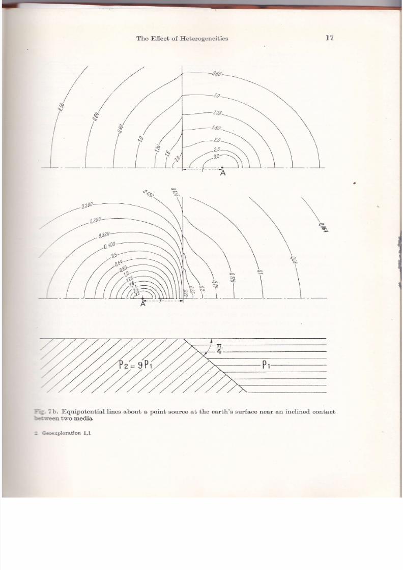
' restricted foreign body would be difficult to see in the vicinitylf the cunent elec-:: lde ; the effect of a contact between t'n o beds of w-idely different resistivities would = risible. f,et us take still another example analog to that given in the first publica-
:t 'n of Conrad Schlumberger relative to the vertical contact between two Jafurials-r'ose resistivit'ies bear the ratio of g. The current electrod.e is in either of the two- :üa (n'igure 7a). We note the ,,attraction,'exerted
b¡, the more resistant meclium':- the equipotential lines and the refraction of these únes according to the la.lv of::.rgents at the contact.
E'1uípotential Línes aboae a Vertical or Inclined, Contact between two Types of Roclcs.-: a region where the unperturbed field woulcl, be uniform, such a contact mani_:-.is itself by a change in direction of the field andby a closer spacing of the equi-: - ,ential lines in the medium of higher resistivity (Figure g). rf, insteacl of vertical
- _ __eqtrpafenlia/ /rhes
. - . .>. Equipotential and. current lines, aü the cRoss sEcTroñ -czrrenf/tttes
--_.ssurIace,duetoauni[ormcurrent,crossingaffi:-- i't between two media " ,Z,Z,pí J//,/A\\\.tc1\*
' :-:ac'ts which could correspond to faults or upturned beclding planes, one is dealing--:L a series of horizontal beds, it is evident that the equipotentül lines at the earth,s'-:i:ce rvould not be disturbed.'Tne intermediate case of clipping beds is ress simple. rn theory at least, the poten----. :-ra,dient, becomes nil or infinite at the contact between ih" t*o media, even
--
=r each of them has a finite resistivity. rrowever, in practice, the media aro- ' =r infinite in extent nor do the resistivities change absoluiely abruptly. tr'igure T b- --'': tho equipotential iines for a contact dipping 45 ilegreesior a resistivity ratio:.
- .r:it€.tc€ of ropography. The prececling discussion s'pposes measurements made' . plane surface of the earth. The presence of relief o" tfr" earth,s surface also-¡.'rbs the field. The current density is increasecl at the bottom of valieys an4 de-:.:.s¿¡l near the top of a hill or mountain (Figure 9). The equipotential sqrfaces will
--
1o..dense in the valley bottoms ancl less dense near the tops of hills and moun_

5/13/2018 Principles of Direct Current Resistivity Prospecting - slidepdf.com
http://slidepdf.com/reader/full/principles-of-direct-current-resistivity-prospecting
t6 Equipotential MaPs
tl;el
Fig. Ta. Equipotential lines about a point source aú the earth's surface near a vertical contact
between two meüa
\
\I
I
\LB
I\\\
__t
l26
5/13/2018 Principles of Direct Current Resistivity Prospecting - slidepdf.com
http://slidepdf.com/reader/full/principles-of-direct-current-resistivity-prospecting
The Effecü of Eeterogeneiüies
.--\ \\2n\\
-.-;..-\ \_.-úf-__\ \ \
/'/l\\l-__-7-_ __A
/t:
1
\\I
?b. Equipotential lines about a point source at tho earth's surface near &n inclined contacüüwomedia
kploration 1,1

5/13/2018 Principles of Direct Current Resistivity Prospecting - slidepdf.com
http://slidepdf.com/reader/full/principles-of-direct-current-resistivity-prospecting
18
z5t4/.3x2/1/
Equipotential llaps
nf lhe earlh
4Bna
a
05
fri
-,-
",-.;:;;
"r"n"**on";'i;",'"ous earttr. Distribution or equipotential and currenb
Iines within the earth. ho : relief with respect to the surrounding plain
| : half-wi.lth of the topographic feature taken at, its mid-height ho/2
In an infinite homogeneous medium, and for the low reliefs that are encounteredmost often, this effect is not very marked. For example, in the bottom of a valley
I00 meters deep and 500 meters wide at the point of half-depth, the spacing of equi-potential surfaces is reduced only by 32 per cent. Figure 9 gives the effect of aneven steeper mountain and valley on a uniJorm field, as well as on the distributionof cunent and equipotential lines within the earth. The effect can become annoyingeither in a very mountainous region or in a region where a surface conducting layerlies on a shallow resistant laver. In this latter case, almost all of the current, linesare concentrated near the earth's surface and any slight change in the thickness ofthe surface conducting layer, modifying the cross-section through which the currentpasses, will have an appreciable effect on the distribution of the fieid at the earth'ssurface (n'igure 10).
II.3 The Effect of AnisotropyPotenti,al Di,stributi,on ,ín AnisotroTtic Med,ia Obta'iner| by Comlpres,si,on ol an Iso-
troytíc Distr,íbution. The equipotential map obtained at the earth's surface in theneighborhood of a curlent electrocle brings out especialJy lrell the phenomenon ofanisotropy. The forms and orientation of the equipotential eilipses are related to thedip of the beds and to the degree of anisotropy.
lt li

5/13/2018 Principles of Direct Current Resistivity Prospecting - slidepdf.com
http://slidepdf.com/reader/full/principles-of-direct-current-resistivity-prospecting
The Effect of -{nisotropr
I---
<ll;t ¿!:,"liiiJ;iLJii,i*1,',i",p,=-,
I
lTTA , : t/a/¿0) +_ LfL
ll
t9
Fig. i0. Effect of topographyin an inhomogeneous earth
(at8r: {or
to
/0
', I _
C'oe'ff'ci'ent ol Aní'sotrop7. Suppose that one wants to cLetermine the potential üs-:ibr¡tion in a meüum having an anisotropy of revolulion. By this, it is meant that,:¡e true resistivity presents a maximum in a certain clirection (transverse resistivity: !r) and a minimum (longitudinal resistivity : p,) in all directions perpendicular:, the first direction. Let l, : Q¡lQt. one can show that the desired. dist"ibutio., of.:,:tential can be obtained by compressing the equipotential surfaces by a ratio of ,1,-' the direction of the axis of rotation, the equipotential surfaces of r"ierence being.:;¡en as those due to the same current source in an isotropic medium l,vhose resistivl-:-; is given by g-:letk, The transverse resistivitv win thenbe itimeshigher.::;n that of the reference meüum and the longitudinal resistivity will be r/; as ñigh" the reference resistivity. The coefficient
^: llala, is called the ,,coefficient
ofi -i>otropy." rt is always great'er than one but, is generaily smaller than t.wo.
E!!ípsoid' and' Ellipse of Aní,sotrolty. rn a homogeneous medium, the equipotential'.':-¿ces about a point source will be ellipsoi<ls of revolution, flattened. in the ratio ,4.
- = notential distribution in planes perpendicular to the axis of revolution will re-: :-:l the same as they rvouid be in the reference medjum of resistivity g_. This,,.;- ploperty shows that, in the case of horizontal stratification, the equipáiential-:! es on the earth's strrface will remain circles that or.re lvouid obtain in an isotropic
!-n I
/20

5/13/2018 Principles of Direct Current Resistivity Prospecting - slidepdf.com
http://slidepdf.com/reader/full/principles-of-direct-current-resistivity-prospecting
20 Equipotential Maps
medium of resistivity p-. Therefore, no surface measurement can indicate lhal amedium has such an anisotropy. In the other extreme case of bed.s upended vertically,the equipotential curves will be similar ellípses elongated parallel to the stratificationand- the ratio of the two axes will be 2.
Apparent ani'sotropy. rn the intermediate case of d-ippitrg beds, where the angle6f dip is a, the equipotential curves will still be ellipses but the elongation wilt beless. This elongation, sometimes known as "apparent anisotropy," is parallel to thestratiflcation and is given by
1fl+lrtarlzu€: |/ t+ranio¿(Fig. 12)
Iormulas lor Macro-Anisotropy. One can demonstrate that the average anisotropyof a succession of beds is characterüed bv
zQihiQú: -r and
If the succession consists of alternating beds of thicknesses ñ, and h" and of resistiv-ities q, and- qr, one has
rl8'e fi(I*e)0¿ : 0r - , pt: 0t, .). . ¡ A,nd /.:rf e p+e
where
f : a'lP, and' e: h'lhr'
Tor a given resistivity contrast, ,t urill be a maximq¡1 for beds of equal thickness. Inorder for i to be as high as 2, it is necessary that the resistivity contrast p be more
than 14 which is not impossible.Efrect of Aní'sotropy on Apparent Resi,stiui,ty. Tine transverse, longituclinal, and
.average resistivities of which we have spoken are the true resistivities of the earth.One would be able to measure them in samples in the case of microanisotropy or tocompute them from a succession of field resistivity measu¡ements in the case ofmacroanisotropy. The apparent resistivity defined above is related to these true re-;sistivities through rather strange relati6nships, that are not at all evident at first sightbut are easily derived by a consideration of the ellipsoid.s of anisotropy.
rn Iigure 11, we show the construction that permits us to compute the apparent,resistivity in the general case of a configuration oriented- obliquely to the strike of
dipping beds. We assume that we are to compute the apparent resistivity gu baseil,on a potential measurement at a point M on t}-:e earth's surface, due to a cu¡rentsource A, given the coefficient of anisotropy /. and the direction of the principal axisof anisotropy which we can term the "axis of compression." This axis of anisotropy.would be normal to the bedding planes. We first construct a vertical section n' paral-lel to the axis of anisotropy and passing through the point Jl[. In this section, we canconstruct the equipotential ellipse, since we know the direction and ratio of the majorand.minor. axes: 2 : q.l F. The e,quipotential circle, correspo.pding to a fictitious iso-tropic medium, from which the ellipse is derivecl. by compression, is the circle of radius a.
!:*la'8r Zhi
lG+rtb@+ p)L*e

5/13/2018 Principles of Direct Current Resistivity Prospecting - slidepdf.com
http://slidepdf.com/reader/full/principles-of-direct-current-resistivity-prospecting
22 Equipotential Maps
The explicit formulas in the general case would be complicated. These complicatedformulas become simpler when the configuration is either parallel or perpendicularto the strike of the beds. In these cases, we have:
q, (par) : pm :/p,1
S,
gu (norm) : Q^le
independent of the dip
alu'ays less than q* .
The Parad,or of Ani,sotropy. Conttary to what one would expect, the apparentresistivity measured in a direction normal to the bedding is less than that measuredin a direction parallel to the bedding. Speciflcally, if the beds are vertical, a configu-ration normal to the bedding planes v'ill give:
gu (norm) : Q'¡l )" : Qt
Thus, the apparent transverse resistivity will equal the true longitudinal resistivitv.This property is callecl tho "paradox of anisotropy."
Measurements Mad,e i,n a Dri,il Hole; Determination ol Dips. If one made measure-ments with a vertical configuration as, for example, in well-logging, one would fintl:
cu (vert) : r,"/ll: n ,-+#;
and it rvould be for the horizontal beds that one would obtain the true longitudinalresistivity.
X'ig. 12. Current electrode buried ina dipping, anisotropic medium
p=lsq E= -i
In principle, one can determine the degree of anisotropy as well as the strike ancld ¡p of the bedding by preparing an equipotential map at the earth's surface with thecurrent electrode at a known depth in a well. If the depth of the current electrodeis D (Figure 12), the distance from the centet of the equipotential ellipses to the topof the well is /, and the ratio of the two axes is e; one would have for the dip :
tan a:'/t -l\
./ \- ,'l'
e=f

5/13/2018 Principles of Direct Current Resistivity Prospecting - slidepdf.com
http://slidepdf.com/reader/full/principles-of-direct-current-resistivity-prospecting
-
Conclusion-s
tr.{ Conclusions
\fe have said that the two most useful zones in the establishment of equipotential*-áps are the zone nearthe midpoint, between t*'o current electrodes and. the zone-rneüately neighboring one current electrode. These zones are privileged because
-t\- present the simplest potential distribution in a homogeneous medium. In the: -"e around. the current electrode, the method has certain inconveniences:
difficulty in bringing out and interpreting deformations in equipotentialscorresponding to a rapidly varying field, even in a homogeneous country-rock;the predominant role played by the exact position of the current electrodewith respect to the inhomogeneity, which requires us in principle to estab-lish several maps for a given region;
and, finaliv, the great variation in ihe depth of the beds involved. as onemoves away from the current electrode,
rltne can overcome the first of these difficulties by plotting the ratio of the true:,:iential to its theoretical value. Ono thus obtains a sort of apparent resistivity, but:.-. 'lepth of investigation wiil vary from one point to another.
is for the dominant role played by the location of the currerrt electrode, it is
=iÉed in one particular case-that in which the electrode can be placed. in contact,v::h a conducting ore body. This method is used frequently in mining exploration': -: ,l.oes not fall within the framework of this treatise.
Tre same troubles are not found when the potential distribution is studied in the: : - = n-here the unperturbed field would be uniform. In fact, because of greater sim-::-:ty in the normal distribution, we have preferred to study the fielcl itself instead. i :he potential. The value of the fietd is constant if the meüum is homogeneous.ll:s. a map of the field will be equivalent to a map of the apparent resistivíty for, -:r*f depth of investigation, assuming the distance betr,veen the current electrod.es--
.- iintained constant.I;¡o variations of this method are still used currently; one, using telluric or natural
r:'=nts will not be studied herein; the other, using the field measured mid.way be-" r.tr two current electrodes A and. B, will be examined in the following chapter.
oo

5/13/2018 Principles of Direct Current Resistivity Prospecting - slidepdf.com
http://slidepdf.com/reader/full/principles-of-direct-current-resistivity-prospecting
CIIAPTER, III
RESISTIYITY PROF'ILES AI{D MAPS
III. L General
The apparent resistivity is nothing more than the ratio of the real value of a poten-tial or a field strength measured with a certain configuration to its theoretical valuewere the measurement made with the same configuration in a homogeneous medium.An apparent resist'ivity map is a map of relative anomalies, usually in the fielclstrength. These anomalies are related to the tength and orientation of the configu-ration rather than to a fixed position of the current electrode and to varying positionsof the potential electrode as is the case of the equipotential map. The resistivit;r
map thus constitutes a choice and a particular grouping of data.The choice of a direction is often difficult. It depends first on the nature of the
problem at hand, but also on the practical possibilities o{ executing the rneasure-ments in the field. Maps or profiles established using a second direction often wouldhelp interpretation but are seldom made in practice.
A given distance between current and potential electrodes corresponds to a set ofdata related to a nearly constant depth of investigation, and thus tá a byer of ear-bhof a given thickness. The dimensions of the configuration will then be chosen in func-tiorr of the depth of the problem in quest'ion. Also, to be considered is the successionof resistivities, determined by electrical sounding and calibrated. if possible by dril-
ling. Hero again, maps based on several lengths of configuration may be necessaryto correctly interpret the results.
III.2 Configurations
The choice of configuration poses absolutely no problem in the prcparation of apotential map. The t'wo current electrodes are kept fixed while ono potential elec-trocle is used to measure the potential üfierence between a moving point and somefrxed, far-removed point. rn the preparation of a resistivity map a large variety ofelectrocle configurations can be imagined. We witl now review the most common ones.
Even if everv configuration must necessarily consist of at least, four electrodes,
two current electrodes called ,4 and B-two potential electrodes called M and -ly', wecan arrange them so that tr,vo have a constant if not negligible effect,. The simplestway to obtain this efiect is to leave two electrodes fixed at some great clistance fromthe points of measurement.
D'ipoles ond' Pri'nciple ol superposi,tion. Thus, if one current and. one potentialelectrocle ate removecl to "infinity," the simplest theoretical configuration possibleis obtained-a "üpole AM" (Fig:ute l3). rn passing, note that the principle of super-position enables us to determine the resuits due to any configuration if we kno.w
those due to the inüvidual dipoles that make up the configuration. rf we o"" vfi)
tf

5/13/2018 Principles of Direct Current Resistivity Prospecting - slidepdf.com
http://slidepdf.com/reader/full/principles-of-direct-current-resistivity-prospecting
-
Confignrations 25
: r denote the potential at' M due to a current electrode A, tlne potential difference:ttween points M and..lü due to current electrodes .4 and B will be given by
(B) 1
vl-¡fI
In theoretical studies concerning the efiects of heterogeneities in the earth on the:'rtential at the earth's surface, it wili be easiest to compute the potential at a given:.'rint due to a single current electrode and then to combine in a convenient manner:re results computed for difierent positions and spacings of this basic dipole. How-:;er, even if the dipole is the simplest configuration in theory, this is generally not,:;,¿ case in practice, particularly because of the very long cables that would have to:e used to connect the electrodes at "infinity."
I ] rr rxrrnnv
(A)
lY:V M
(A) I rn)
v -lvYL.]f
AT INFINITY
OUAORIPOTE EOUIVAI.ENI TO TRIPOLE AMN.IM lNH
I
I
iB
Fig. 13. Various configurations
Tripoles. If we remove to infinity only one electrode (n'igure 13), we obtain a.dpoie AM N or ABM , both being equivalent by virtue of the principle of reciprocity.F:r practical reasons, we most often remove one of the current electrodes; it is found::at fluctuations in natural potentials make the measutement of potential üfierences:":.ther difflcult over long lines. These natural potential differences, and thus their':.:tuations, are roughly proportional to the distance between the potential elec-
- - les.The tripole that is used the most commonly is that in rvhich the three electrod.es
:r= arranged. along a straight 7ine, A being outside the interval MN. Normally, either-;e tlrree electrodes are spaced. equidistant or the interval MN is madesmallcom-:,red to the distance of M and. N to A. In the latter case, the potential difference---;ided by the interval -M-l[ approximates the field strength at the midpoint O be-,-.er l[ and -lü.
As for the second. current electrode, insteacl of being where its influence is negligible- - either of the potential electrodes, it may be placed in such a manner that it has,t: same effect on both potential electrodes. In homogeneous earth for example, i{,t. second current electrode is placed. along the perpendicular bisector of the line:..:rreen the potential electrodes, it will create the same potential at each of the poten-
(p/a,t w?w) I produ
ces some lolenlia/ nlMa¡dN

5/13/2018 Principles of Direct Current Resistivity Prospecting - slidepdf.com
http://slidepdf.com/reader/full/principles-of-direct-current-resistivity-prospecting
26 Resistivity profiles and 1\[aps
tial electrodes and thus satisfies our requirement. However, in practice, it is neces-sary to remoYe the current electrod.e an appreciable distance so that one can neglectany asJrmmetry introduced by inhomogeneities in the earth.
The tripoles ofier a considerable advantage in rough terrain in that only three elec-trodes and correspondingly less cable are required to be moved" to execute resistivityprofrles. I{owever, their asymmetrical character usually makes them less d.esirablethan quadripoles.
Quad'ri'poles. In most of the complete quadripoles used, the {our electrod.es arearranged along the same line. The two potential electrodes are normally inside of thecurrent electrodes and generally are symmetrieally üsposed with respect to the centerof the configuration. When the configuration is asymmetrical and -44-l[ is much nearerone of the current electrodes than the other, as is normally the case when the poten-tial electrodes are outside the current electrodes, one catr imagine that he has animperfect tripole; the influence of the second current electrode is slight but not neg-
ligible.wenner and, Bchlumberger configurati,ons. The two quadripoles by far the most
used (X'igure 14) are still the Wenner configuration in which the electrocles are equallyspaced, and the Schiumberger configuration in which the distance MN is smail withrespect to the clistance ,4-8, generally smaller than ABl5. With the latter configura-tion, the ratio of the potential difference to the interval MI{ is practically equal tothe field strength near the center O of the configuration, since the field is nearlyuniform in the neighborhood. of this point.
OUADRIPOTE
AMw" Mw Nw = Nw B :w€NNrR coNFtcuRATloN
Ms Ns - aB :scHLUMBERG¡R coNÍrGURAIrox5
+-----18 DouBL€ Drpolr Y--+..wFig-. |a. _Configurations using quadripolesand double üpoles
conft,guration wi,th MN outsid,e. Among the quadripoles in which MN is exterior
to AB, the only ones that are not imperfect tripoles are those in which the intervalsMN and AB arc both small with respect to the separation between them. such aconfiguration is called a clouble dipole. The advantage of this configuraiion is thatit requires much less cable for a given depth of investigation than do other configu-rations. This is because the depth of investigation is essentially determined by theshortest, dist'ance that separates a current electrode from a potential electrode. Thedisadvantages are the comparatively low potential difference between the electrodesMN Íor a given value of the applied cwrent and the preponderant role played bythe nature of the terrain near the cunent electrod.es AB.In fact, the potential dif-ference varies inversely as the cube of the distance between the current electrodes

5/13/2018 Principles of Direct Current Resistivity Prospecting - slidepdf.com
http://slidepdf.com/reader/full/principles-of-direct-current-resistivity-prospecting
Configuratioas 27
and the potential electrodes in this configuration, whereas in the Schlumberger con-fguration it varies inversely as the .qour" of the electrode interval -48. This con-fguration has been used very üttle in practice (except in USSR).
Carpenter Configuration A finai variation of the in-line quadripole was recentlyproposed. by canrnNrnn (1955)*. rt consists of placing oná of tñe potential elec-t¡odes inside the current electrodes and one potential electrode outside. In fact, itcould be interesting to use all combinations possible by interchanging the electrode
Fig. 15. Three independent quadripolecon[guratrons
positions. Howevet, the principle of reciprocity tells us that there are actually onlythree independent combinations, any complete interchange of potential and currentelectrodes leading to an equivalent system (X'igure 15). A comparison of the resultsobtained with these three difierent hook-ups permits us to und.erstand the influence
d the zone near each of the electrodes and can faciütate interpretation.AB Rectangle. Among tü.e configurations in which the electrodes are not on thesame line, the only one cunently used is that in which MN is displaced. laterallyrith respect to the line of the cunent electrod.es AB; MN remains parallel to AB and.not too far from its midpoint O. This technique permits the investigation of a ratherexüensive zone by displacing only two electrodes in an area where the field*hength is about uniform. It is evident that the depth of investigation remains aboutthe same {or all such measurements. This configuration is the one called the ',rectanglenethod" to be discussed in detail ]ater.
' conf'gurations wi,th more than four Electrod,es. Finally, there are configurations
th¿t have more than four electrodes, and usually more than two potential electrod.es.Some of these are in principle nothing more than one of the four electrod.e configu-¡ations previously described.above, and they are used. only to accelerate the wórkmd to increase the data. These are the ones in which different pairs of electrodesa¡e used- simultaneously or separately to yieid independent potential differences. Anexrmple is the Lee configuration which places a fifth electrode at the midpoint ofúhe Wenner configuration. The potential d.ifferences MP and, P-lü are then measured.aimültaneously. The same is true of certain other configurations in which there aremveral pairs ,ilf.lü symmetrical about the center of the configr¡ration.t ce¡'r¡Nrnn, Enrc, 1g55, some note¡ concerning tho wenner con{iguration
-
Geophysicalhoepecting,
3: 388-402.

5/13/2018 Principles of Direct Current Resistivity Prospecting - slidepdf.com
http://slidepdf.com/reader/full/principles-of-direct-current-resistivity-prospecting
28 Resistivity profiles and Maps
I![easurement ol Potential Drop. In other cases, we can measure direcgy certaincombinations of potential difierences measured with üfferent pairs of potential elec-trodes. such is the case for the potential-Drop-Ratio method. lnu.o*f io which theelectrod.es are aligned in the foltowing order: B well removed., a, M, p and -l[. Theratio between the potential drops M P and, P-l/ is then measured. This methoci. meas-ures in effect a sort of derivative of the field strength, and" consequenily is verysensitive. IIn-fortunately, it is sensitive above all to local inhomogeneities near thepotential electrodes.
computatí,on of Apporent Resí^ti,aity-The coefficientK. x'or any of these configu-rations, it is easy to write the expression for the apparent resisiivity following"itsdefinition: ratio between the measured value of the parameter in question urrJ it*theoretical value in a homogeneous medium of unit resistivity. Thus, for a givenquadripole, v'e will have (X'igure 16) :
The coefficient of a v lr )n this formula depends only upon the geometric configu-ration and is called the "geometric factor" or is simply-designat-ed as K. x'or thesymmetrical Schlumberger configuration,
":
"V*]f!t : " l4!t_lLN)' I
If the lengths are given in meters, potential differences in millivolts, and the current ir,
milliamps, the resistivities will be expressed- in ohm-meters. rn the same manner, inthe potential-drop-ratio method, if -R is the ratio of potential differences, the apparentresistivity will be given by (X'igure 16):
NUN-AP\n:-:A AP-AM
K:2n ( I _ r l_/ r _ r i\AM ANI \B,u I¡n'J¿v
Q": E tFor configuration symmetrical about 0:
_ AM.ANA:nMN
¿vQu: Il I
Potential-drop-ratio method
PMA_1tt:Áp-¿a
AN.- AP
Qa:-t1 ¡
with n.: ¿-vtÁVz
F'ig. f 6. Determination of the geometric factor K

5/13/2018 Principles of Direct Current Resistivity Prospecting - slidepdf.com
http://slidepdf.com/reader/full/principles-of-direct-current-resistivity-prospecting
Methocls of Application
m.3 Methotls of Application
TTT. 3a llorüontal Profiting
Any one of the configurations d.escribed above can be used to establish resistivityprofiles or maps. To that end, one must either move the complete configuration aftereach measurement or cause the electrodes -MN b occupy a series of different positions-r.rctn'een each movement of the current electrodes ,48. This latter option is used inthe case of AB profiles or rectangles. fn both cases, the group of measurements will'.orrespond. to the same depth of investigation or to several, nearly constant values.rf that depth.
Choice ol Li,ne Length. Configurations fixed. in length are displaced, along the line-'i electrodes, and, if they are short enough, the cables may be dragged along the¡round (x'igure r7). This type of surveying is called "Horizontal profiling."
Apparent resistivity curves
P"
i=-\/\-
---/c' , , , ' t t
/ZJr'JO
29
Displacement of the conflguration
=:izontal proflling with Schlumberger conf.guration Ilorizontal proflling with lee conflguation
17. Presentation of results corresponding t'o configuration displacements as sho.wryl
\nrspg the configurations commonly used, the simplest is the symmetrical qua-iipole aMNB. The choice of the electrode separation AB for a given problem is an-:nportant and difficult question that can be answered only after a certain amount:j trial and error. Some possible cases are cited as examples:- Suppose that it is desired to map the nature of a structure masked by a variable:ij¡tness of overburden; one should then take a line as long as possible and perhaps¡¡ much as 40 times the minimum thickness of the overburden. The effect of the;,'rring thickness of overburden can be especially bothersome if its resistivity is:i:h.

5/13/2018 Principles of Direct Current Resistivity Prospecting - slidepdf.com
http://slidepdf.com/reader/full/principles-of-direct-current-resistivity-prospecting
30 R,esistivity profiles and Maps
2) If iL is desired to study the nature of an alluvium more or less argillaceous, ,48must not be more than two to four times the minimum thickness of this alluvium.The measurements are more sensitive to the thickness of the alluvium as the resis-tivity contrast is increased between the alluvium and the underlying rocks. I{ote thaó
the addition of a thin, shallow layer can compricate the picture by imposing a lowerlimit on the electrode separation ,48.3) Finally, if it is desired to follow the variations of the thickness of the overburden,one must choose an electrode separation that is neither too long nor too short-forexample, five to ten times the average thickness of the overburden. This suppositionis based on the case of two very homogeneous beds lr,.ith a strong resistivity con_trast. Horizontal profiling is rarely applicabre to this sort of situation.
Fot MN, an electrode separation.is taken between one-tenth and one-third theseparation AB.Ibe interval between successive points of measurement will d"ependon the precision which is required of the suryey; normaliy this interval will equalthe distance l4-0tr' Since
thisprocedure
involves adjacent measurements of the poi"o-tial difference MN, it leads to continuous profiling that cannot be attained inelec-trical sounding.
When one profile is finished, adjacent parallel and equally-spaced profiles are exe-cuted until the entire surface to be surveyed is covered. The distance between acljacentprofiles will always be at least as great as the distance between measurements alongthe profile, and often will be several t'imes greater. In fact, the profiles wilt usuall!be oriented normal to structures so that we may expect to find somewhat similar re-sults from profi1e to profile.
Use of Seueral Li'ne Lengths. Measurements with a single electrode separation mayoften be insufficient, even more so since the depth of investigation for*a given elee-
trode separation may vary considerably depending on the vertical succession ofresistivities in the sect'ion. Rather than do the measurements twice in two separatepasses, we may use a technique such that measurements with several electrod.l sep-arations are made simultaneously with a single pass along the profile. x'or rathershallow problems, we can use a symmetrical configurution ia' Mñ a, n *i*tour cur-rent electrodes. For a given position of Ml{,measurements aro mad.e first withthecurrent flowing between A' and B'. The cable is then d.isplaced and the measure_ments repeated at the next station. Besides the obvious aclvantage of providing twodepths of investigation, this technique also enables us to identifylfiects of near sur-face inhomogeneities as the individual electrodes pass over them.
confgurati'on with Mr{ outsid,e. with longer rines, an asymmetrical configurationis sometimes used with two current, electrocles and several pairs of potentlal elec-trodes exterior to AR and generally adjacent to one another: BA MN M'N' ... (Fig_ure 15). There are thus provided a set of configurations with increasing depths of ii-vestigation, since these depths are essentially governed by the üstance from thepotentiai electrodes to the nearest current electrode. The measurements for the dif-ferent pairs of MN may be made simultaneously after which the configuration ismoved a distance generally equal to the ilterval l'l4ll. This technique permits the useof most of the potential electrodes for measurements at different d.epths of investiga-

5/13/2018 Principles of Direct Current Resistivity Prospecting - slidepdf.com
http://slidepdf.com/reader/full/principles-of-direct-current-resistivity-prospecting
Methocls of Appücation
tion -without actually moving them. The technique also permits us to obtain a largenumber of readings in a short time, but the interpretation of the data is sometimÉsdelicate. In fact, since the current electroile nearest, the potential electrodes entersir1to play almost alone, the effect as it' crosses a structure is nearly double that of a
srmmetrical configuration and should thus be sought carefully on the profiles ob_tained.
Use ol Beaeral Pa'írs of Potential Electrod,es. The use of several pairs of potentialelectrodes for each position of the current electrod.es may have as its only aim theseparation of the efiects due to movement of the two kinds of electrodes. The most'oormon technique in this category uses a symmetrical configuration wibh three po-:ential electrodes MOI{, the center electrode being p}aced" at ihe midpoint of the line-lB. The T,ee configuration is an example. For a given position of the current elec-irodes, the potential difierences betureen MO and OI{ arc successively measured, afterrhich the configuration is moved. forwarcl an interval equal to the interval MO (Tig-
'rre l7). In this fashion, we have:for the same measuring element Mo or or, two values of the apparentresistivity corresponding to tu.o successive positions of the line ,aB. The dif-ference between these two measurements is a measure of the effect of theposition of the current electrodes;for a given posiüion of the line AB,two varues of the apparent resistivitycorresponding to two successive positions of the potential electrodes MO and,ON , in other words, an element of the resistivity profile .48.
Since the tot'al Mr{ is short compared. to the length AB, Lhe two parts Mo and,
'-¡^\ remain very nearly at the center of the configuration and all of the measure-rents have approximately the same depth of investigation. ft is also evident that-ne could combine the above techniques such that two d.epths of investigation were:,railable using a configuration with seven electrodes AA'MOI{ BB, .
m. 3b The Rectangle MethodProfiles with AB rired, and, AB Rectangles. The same principle of seyeral poten-
ial measurements for a given position of the electrodes AB can be extendeá con--J.erably, and thus has given rise to the technique called "profile and rectangl e A8.,,ás long as the electrodes MN rcmain in line with the current electrodes, the term.profile" is used;
when the element,Ml[ is moved off the line of current electrodes,:rt remaining parallel to it, tho term "rectangle" is used. The potential electrodes,:e usually kept within the middle third of the electrode separation aB, and. within; lateral distance from the rine AB equal to AB 14 (Eigare Ig). A rectangle of these:'nrensions (AB13, AB12) is such that the field strength in the interior of tñe rectangle,-'l the depth of investigation will be nearly constant if the earth is homogeneois.l"e interval ,44-l/ is kept comparatively small (,48/b0 to ABl25) so that.we can make, -arger number of measurements within a given rectangle without moving the cur-:'rt electrodes. X'or each position of ,48 this method leads to a small -up oÍ the fietcl.-length, or, more exactly, to a map of the component of the field, strength parallel
31

5/13/2018 Principles of Direct Current Resistivity Prospecting - slidepdf.com
http://slidepdf.com/reader/full/principles-of-direct-current-resistivity-prospecting
ResistiviüY Profrles and MaPsto
Fig. 18.
Profrles and rectangle AB
tothelineAB.Thevafiationsofthisfield,relativetothenearlyuniformfield.itthe
earth were homogeneous, are relat'ivelyeasy to interpret'
Inreality,however,wedonotdrawamapoftnefield'strength'butoneoftheap-parent resistivity *hi";]. ;;|r[y related.lo the field st'rength by a factor nearly
equal to unity. The"or.ün-.t
i, prácisely the inverse of the field strength in a homo-
seneousearthataglvenpoint.ForthedimensionsoftherectangledescribedandIo, u. infinitesimal MN,t'!rcconstant' rangel from 1/t'4 on the edge of the rectangle
on the'ineABt"
1.;';;;;" *iap"irt oItU* edge of the.rect'angle parallel to the
'neAB.The need ,"'"llp*"*if.i- factor {or "u"i
*"u**ing point in terms of the
"Árif"tgtl,M'lü is an in*convenience of the rnethod'
Depth of Inuesti'gatíor'-¡¡o' oy AB Rectangle)' As for the depth of investigation'
italso varies slightly *ii'fu'" the rectangl"; ií i* largest at thl mid'point and gets
slightly smaller to*u"A*lfr" "ag.. of the r"ctangl". Iio*"t"r, the computat'ion ofa
factor to normalize all measurÁents, to ,rhat one would get at a given point with
a given electrode '"p;;ti";AB' now depends on the succession of t'rue resistivities
withintheearth.rn"""to,",sucha"o,,""tio,'factorcanbecomputedonlyinthecaseofavefysimpleh¡lothesissuchasasinglehomogeneousbedlyingonanin.finitely resistant or perfe"tty cond'u-cting sulo-stratum'
Tying AB R,ú*';;;; rog'ther' TJsaÑ' th" u''"u' to be studied is much larger than
the area of the rectangle most appropriate for the problem in question; in such a
case, the large area is Jovered *itf, u succession of aijacent rectangles each with an
appropriatepositiorrofthecurrentelectrod'es.Matchingtheresultsofadjaeentrec-
tangles sometimes p"-". l-pr"¡lem; in fact,, themeasurements are normally not the
same when made along the common t orrtí* between two adjacent rectangles with
tv¡odifferentpositionsofthecurrentelectrodes.Thiseffectisdue,'notonlytothedetailsofcurrent,¿i.,'it,o,io,'intheearth,buta]sotothespuriouseffectsoftheearth immedi-t"ry ;;;;;J the current, electrocles. In certain cases, it' will be neces-
sary to smooth trr" *rf"r
trre yhole area to take out irregularities rvhere the various
rectangles touch. rt*J'p""r"*t1e to apply the same correction factor t'o all of t'he re-
sultsofagivenrectangle,choosingthecorrectionfactorsinsuchawayastoobtainthe optimum *ut.rirlti uli th""¡oraers of the rectangles. rf this matching proYes
4-4 Profi/ AB4-4 Rectang/e,la

5/13/2018 Principles of Direct Current Resistivity Prospecting - slidepdf.com
http://slidepdf.com/reader/full/principles-of-direct-current-resistivity-prospecting
Methods of Application 33
to be too difficult, a more complicated technique must be adopted in which the cor-rections vary from point to point within a given rectangle.
In this technique, the fact that only trvo electrodes are moved between successivemeasurements
has two advantages. In the first place, it facilitates the execution ofsunreys in difficult terrain; ancl in the second place, which is more important, itclirninishes the number of perturbations due to changes in the nature of the soil inthe immediate vicinity of the current electrodes.
In review, the disadvantages of the technique are:
I. the depth of investigation is somewhat .i'ariable;
2. it is sometimes difficult to join the results of adjacent rectangles;3. lengthy calculations are needed to compute geometrical coefficients nor-malizing the results of all the points within a given rectangle; and4. there are certain diffrculties in the execution of the measulements such
as a need for multiple conductors, line leaks needing to be checked, etc.There are two cases in which the technique of rectangles finils its greatest use, in
nining problems and in tectonic problems involving moderate or great depths. trnmining problems, it is advantageous to use an interval -MN very small in comparisonrr-itlr the interval AB. At the same time, imperfect joining of adjacent rectangles isnot bothersome, for the aim is simply to map low resistivity trends and the absoluter¿lues of the resistivity are not important. In tectonic studies, for example, with ,48ec¡ual to 6000 meters or longer, it is not practical to drag the cables from station tostation in horizontal profiling. Thus, the rectangle method is preferrecl because itpermits a much more rapid advancement.
The Telluric Method'. The distribution of the field, due to natural currents in tel-luric prospecting, has man¡r points in common with the distribution of the field inthe rectangle method. fn particular, the manner in which geoiogic structures mani-fest themselves is quite similar in the two methods. The conditions favorable to theu._re of these two methods are also similar, and, therefore, it is useful, if we are to'listinguish betu'een their similarities and differences, to bring to mind. an outline ofthe principles of telluric prospecting.
Teliuric prospecting is founded on the fact that spontaneous currents flow in thee¿rth and behave as though they came from extremely distant sources. Thus, telluric,:urrents are uniform in a homogeneous earth. The conditions are the same as would
i,.e expected near the center of a large rectangle AB, exeepl for the advantage thatno current cables are needed in the case of telluric currents. The exception to thissirnilarity is that teliuric currents are quite variable in time as much in direction ofÉow as in magnitud.e.
The variation in intensity imposes the use only of comparative measurements. n'or-sample, the field intensity is measured at points in the area to be prospected reiativeto the field. intensity at a fixed reference point. I'Ieasurements to be compared mustbe made at the same instant. The measurement of the current is impossibie in this'.ase, and, in a sense, is replaced by the measurement of the field strength at a point-rf reference.
: Geoexlloration 1,1
5/13/2018 Principles of Direct Current Resistivity Prospecting - slidepdf.com
http://slidepdf.com/reader/full/principles-of-direct-current-resistivity-prospecting
34 Resistivity Proflles and Maps
The variation of the direction of flow leads us to measure two potential differencesMN, generally at right angles to each other. The two components then permit us todetermine both the magnitude and. direction of the field vector. The relationship be-tween tho field vectors at the station and the point of reference can also be quite
vaúable, depending on the direction of the field. This is not unexpecúed (Figure 19)because different values of the apparent resistivity may be obtained depending onthe direction of the current Ttne AB with respect to structural trends, other thingsbeing equal. The difficulty of choosing between the various ratios of the field vectorsis overcome through a remarkable property of telluric fields. The areas swept by thefield" vectors at two different points, during the same interval of time, bear a ratio toeach other that depends only on the relationship of the geologic sections at the twopoints.
It is this ratio of areas, a sort of average of fields taken in all directions, that is thcfundamental parameter in telluric prospecting. It is easy, however, to define a similar
parameter using artifi.cial currents. To do so, we must use two current lines -48, longas compared to any structures present or to d.esired clepths of investigation and atright angles to each other.
We measure with each the magnitude and direction of the field vector at the centerof the configuration. The area of the triangle formed, by the two field vectors, thusmeasured, will everywhere be proportional to the areas measured in the telluricmethod.
There exists, moreover, a simplified version o{ the telluric method that is evenmore like the rectangle technique and that is used in regions where the general struc-tural trend, or at least the trend. of the structures sought, is rvell defined.. In thissimplified method, only the component of the field vector normal to the general strikeis measured.
Respect'í,ae Ad,aantages of Telluric and, Rectangle Method,s. The respective advan-tages of the two methods are as follows:
Telluric:
1. easier execution of measurements due to the suppression of current lines;2. great depth of penetration, Iimited only by the skin-efiect;3. information on structures of any orientation, except those parallel to theprincipal direction of culrent flow; and
4.no
needto tie the rectangles together.
Rectangle -48:1. depth of investigation adaptable to the problem in question;2. current can be directed so as to give maximum effect over the structureto be studied.;
3. absolute measurements giving the apparent resistivitv instead of relativemeasurements; and
4. use possible in regions perturbed by industrial curents.
#i'i
ryttir

5/13/2018 Principles of Direct Current Resistivity Prospecting - slidepdf.com
http://slidepdf.com/reader/full/principles-of-direct-current-resistivity-prospecting
Methods of Application
III. 3c Presentation of ResultsThe presentation of the data obtained by these methods lead.s to no particular
problem. In the case of horizontal profiling, with one or more electrode separations,we can first of all draw resistivity profiles for a given line on the ground. There willbe one curve for each electrode separation used. On the abscissa will be plotted a,point representing the position of the midpoint of the configuration at each measure-ment; at each point the value of the apparent resistivity is plotted on the ordinateusing a linear or logarithmic scale as appropriate.
fn the case of the asymmetric configuration srith l/ff outsid.e the current elec-trodes, it.is convenient to plot the value of the apparent resistivity at the midpointbetween the two potential electrodes. This convention is arbitrary and it is ,r.."-r*u"yeach time to note on the graph what convention has been used, as well as the positionof the current electrodes.
The results of a group of profiles are represented in the form of a map, one forcach electrode separation used in the survey. on the map is plotted. the midpoint ofMN for each measurement and. the corresponding value of the apparent resistivity.Contours are then drawn representing points of equal resistivity. TLe contour intervalmay be chosen using an arithmetic or a geometric progression as desired.
In the case of horüontal profiling with the Lee configuration discussecl above, theapparent resistivities are plotted at the corresponding midpoints oI Mo and oll;thus, for a given position of the current electrodes aB,two values of the appareniresistivity are plotted and connected with a ]ine. conversely, for a given point onthe abscissa, there are two values of the apparent resistivity representing twosuccessive positions
of the current electrodes ,4,B (Figure t7). I{ormal American plotof data from the Lee configuration differs from this representation in that tworesistivity curves are plotted, one from the MO measurements and one from the OI{measurements. In each case, tho apparent resistivity value is plotted at a position,of the midpoint of the corresponding potential electrodes, Mo or oI{.
The resistivity profile thus obtained reveals, by its discontinuities, the effects dueto the passage of the current electrodes across faults, etc. tr'inally, a resistivity mapcan be prepared from a series of profiles. when ptotting a map from this sort oi ,l*tithe average of the two values of the apparent resistivity at ách point is taken.
A map of apparent resistivities is obtained directly, in the rectangle method, whenall of the rectangles are plotted and smoothed as necessary.
III.4 Effeet of Yarious StructuresResistivity profiles and maps obtained over a given geologic structure d.epend on
the electrode configuration used and on its orientation. Becáuse of the priiiciple ofreciprocity, it is theoretically sufficient to compute the potentiai at all poirrt* Jr.", u,structure due to a single current electrode as it is moved from place to place. Thisin itself is often a difficult problem. In practice, it is more interesiing to compute theapparent resistivities considering alt of ihe elecfrodes in a given configuration. Certaincatalogues exist indicating the resistivity profiles that are obtained, over some simple,structures with variors relative orientations for a given configuration.
.ti)

5/13/2018 Principles of Direct Current Resistivity Prospecting - slidepdf.com
http://slidepdf.com/reader/full/principles-of-direct-current-resistivity-prospecting
36 B,esistivity Profiles and Maps
III. 4a ,4-B Rectangle
The simplest problem is that of a rectangle,4B, since it is to the first approximationa determination of the perturbation of a uniform field by a given inhomogeneity.Ilowever, it is o{ten helpful to consid.er that the current electrodes are not actuallyinfinitely far away.
Approximate Cylind,rical Structures and, Approrimate (Jniform Field,s-Choí,ce of L,í,neOr'íentati,on. A cylindrical structure is one having a nearly uni{orm cross-section in-finitely in both directions along its axis. A cylindrical structure would have no effecton a field that was really uniform and parallel to the axis of the structure. However,the fie1d due to two current electrodes separated by a finite distance.4B will be some-
AA/Y.S P/4nAU tl f0,tlPl/tIufrt
\
s.Q
ñt
s**N
N
$
A1 A2 A.
Llt-f .t
/y
PIAN //fW
+f ++
L'of earhl
+J-H1/'1
+l+//
4
f0R /V'fA$Uff/ulfl/ft 0/y M00fl:A8=ga
/V/V = a/zb:c : 2an-/!r'*
Fig.19. Profiles across rectangle AB over aresistant anticline
-f//V/ftAB (meqsured)
IJ
I

5/13/2018 Principles of Direct Current Resistivity Prospecting - slidepdf.com
http://slidepdf.com/reader/full/principles-of-direct-current-resistivity-prospecting
Effect of Various Structu¡es
what perturbed by a cylindrical structure parallel to the line AB,evennear the centerof that line. conversely, a structure of great but finite length will always perturbsomewhat a uniform field, even if the field is parallel to the structure. However, it is
true that the effect of such structures is always more marked on a field that is per-pendicular to the axis of the structure. It will be ad.vantageous therefore to use suchan orientation of electrodes when searching for elongated structures.
- The foregoing principles are illustrated by Figure 19 which gives profrles obtainedfrom a reduced model of a rectangle AB over a resistant anticline. In A are shownthe profiles when the line of electrodes is parallel to the structure and in B theprofiles when the two are perpendicular. The fields measured vary from those com-
q-
Fig. 20. Effect of a buried..perfectly conducting pipe
PLAN V IEW
A B PtRPENDTCULAR to PtPE
A B pAnetlrt lo p¡p¿
;Jz;l
z^t
< o'2
o'1
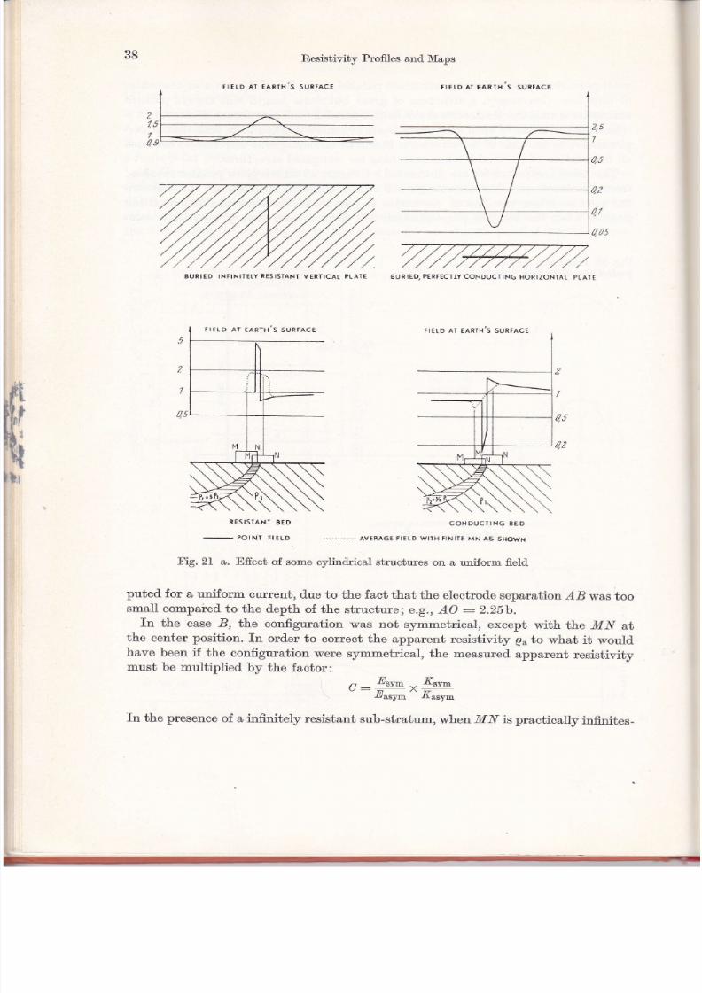
5/13/2018 Principles of Direct Current Resistivity Prospecting - slidepdf.com
http://slidepdf.com/reader/full/principles-of-direct-current-resistivity-prospecting
rIE[D A¡ EARII{ S SURfACT
38 Resistivity ProfiIes and Maps
BURIEO, PERTECTIY CONDUCTING HORIZONTAL PTATE
2
7
q5
RESISIANT BED
-
POtñt HtLD
Fig.21 a. Effect of some cylindrical structures on a uniform field
puted for e uniform cuffent, due to the fact that the electrode separation r4B was ioo
small compaied to the depth of the structurei e.g., AO :2.25b.In the case B, the configuration was not s¡rmmetrica,l, except with the MN atthe center position. fn order to correct the apparent resistivity q, to what it wouldhave been if the configuration were symmetrical, the measured. apparent resistivitymust be multiplied by the factor:
ñ Ztv- ., Ktv-":z*"-^r".";In the presence of a infinitely resistant sub-stratum ,when MN is practically infinites-
TIELD AI EAR¡I{ S SURTACE
BURIED INf INITETY RESISTANI VERfICAL PLAIE
r¡ero ¡t e¡n¡x's sunr¡ce
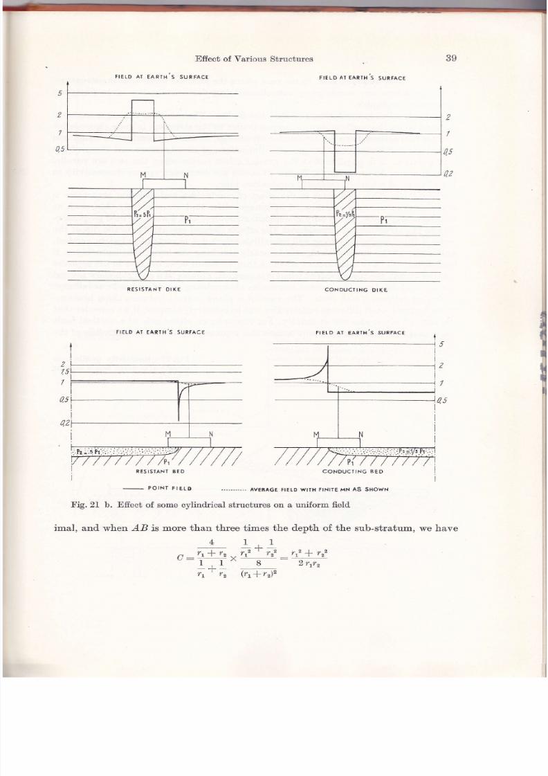
5/13/2018 Principles of Direct Current Resistivity Prospecting - slidepdf.com
http://slidepdf.com/reader/full/principles-of-direct-current-resistivity-prospecting
rIEID A] EARTI{'S
Effect of Various
SU R FACE
Strrctures 39
FIELD AT EARIH S SURTACE
5
2
7
as
2
7
q5
02
RESISIANf OIXE
FIELD AT EARTH S SURfACE
-
POINÍ FIEI.D
FIEID AT EARTH S SURFACE
lql -,t.
05
I
I))i
7
0,5
CONDUCTING 8ED
......"'.. AVÉFAGE F¡TTD WIIH f INITE MN AS SHOWN
Fig. 21 b. Effect of some cylindrical structures on a uniform field
imal, and when AB is more than three times the depth of the sub-stratum, we have
! 1+1"^ rt-frr-.rr2 ' rr2 rr2* rz2" I,I" 8 2rrr,
r, ' r, (rr*r")"
CONDUCTING OIKE

5/13/2018 Principles of Direct Current Resistivity Prospecting - slidepdf.com
http://slidepdf.com/reader/full/principles-of-direct-current-resistivity-prospecting
Ét
t[{
ütr
40 Resistivity Profiles and Maps
where r, : AM and r, : BM.ktthe case where the lines are parallel to the structure,the expressions are much more complicated but fortunately the corrections are
practically negligibie.Anoma\íes Dueto Cond,uctí,ae and, Reti,stíae Bod,ies. The rule that the larger anomaiy
is found when the configurationis perpendicular to the structure is more rigorous for
resistant structures than for conductive structures. In fact, for cond.uctive structureswith certain relationships between the dimensions of the structure and those of the
configuration, it is possibte that the greater effect occurs when the two are parallel
to each other. As an example, Figure 20 shows the computed apparent resistivity inthe vicinity of a buried, perfectly conductive pipe.
Thí,n Bed,s. This differenco irr the efiect of conductive and resistant structures is
still clearer in the case of extended inhomogeneities that are relatively thin, such as
thin beds and veins. When only cyiindrical structures and a uniform field perpendic-
ular to the structures are considered, the effects depend essentially on the dip of the
beds. A thin, conductive layer will have little effect if it is vertical or nearly vertical,
unless one of the current electrodes is nearly touching the layer. The same layer, ifhorizontal, will have a distinctive effect. A thin, resista,nt layer behaves in the opposite
manner-being the more evident when it is vertical. X'igures 21 a and 21b show several
examples of this type, the current electrod.es always being consid.ered to be at infrnity.Contact between Thictr Bed,s. The case of a plane eontact, between thick homoge-
neous formations of different resistivities rvill be relatively simpler, if we consider thatthe current electrodes are at infinity. For example, on either side of a vertical faultone would find constant apparent resistivities representing the true resistivities of the
Frg.22. Resistivity profile overa vertical contact and a dippingoontact

5/13/2018 Principles of Direct Current Resistivity Prospecting - slidepdf.com
http://slidepdf.com/reader/full/principles-of-direct-current-resistivity-prospecting
Effect of Various Structu¡es
FIELDAT THE EARIH,S SURÍACE
Fig. 23 a. Comparison of the influence of cylindrical structures and domes of the same diameterwhen the current electrodes are far removed
Fig. 23b. Variat'ion in the maximum reliefin the field as a function of the height of acylindrical structure
or adome,
when thediameter equals the depth to its top
4T
5+
3
2
1s
7
5
4
3
2,5
2
72ii:s-Ñ(\\rk
Cross ¡eclnn of enrlh

5/13/2018 Principles of Direct Current Resistivity Prospecting - slidepdf.com
http://slidepdf.com/reader/full/principles-of-direct-current-resistivity-prospecting
42 Resistivity Profiles ancl MaPs
formations; in the vicinity of the contact, there ¡¡¡¡ould be a grad.ual transition from
one to the other, the rate of transition depending on the measuling interval MN.Inthe case of a dipping contact, there would still be the two steps. In reality, especially
in this last, case, it is more often necessary to take into account the finite distance
between the curent electrodes. X'igure 22 shows a profile AB ovet a vertical fault as
compared to one over a fault üpping 45 degrees.
Morrn, anil, Domes. Inhomogeneities in the form of a mass or dome al'ways have
a jess marked effect than an extended one; this difference becomes even greater as the
inhomogeneity is more deeply buried. This is obviously due to the fact that the current
can flow around the obstacle of this shape more easily. We saw earlier in Chapter IIthat the effect of a spherical mass varies inversely with the cube of the d'epth of its
center, but that the perturbation d.ue to an infinite horizontal cylind.er falls off only
as the square of the depth of its axis.An uplift of an infinitely resistant sub-stratum in the form of a circular dome, ap-
proximated. by a vertical circular cylinder, u'ould modify a uniform field only ten'percent if the top were buried" to a depth equal to the diameter of the dome, regardless
of the vertical extent of the dome. Figure 23 shows such a case with two different
depths of the dome, in comparison with an anticline of infinite extent.
Efiect ol Ani,sotropy. Folded bed.s can modify the field distribution by their micro-
scopic or macroscopic anisotropy even il they are homogeneous. In fact, the current
tends to follow the ürection of bedfing in which it encountels the least, resistance'
Once again, the field. in the direction perpenücular to the strike of the beds is
particularly affected, the current density being higher over the summits of the
ll'/,37211
x049
08
47
46
0,5
Fig.24. Effect on a uniform fleld of an eroded. anticline andsynclile. Coefficientofanisotropyis í.4, which could correspond. to a succession of thinly bedded sands and clays with pr/p. :20

5/13/2018 Principles of Direct Current Resistivity Prospecting - slidepdf.com
http://slidepdf.com/reader/full/principles-of-direct-current-resistivity-prospecting
Effecü of Various Sfructures 4g
anticlines and. less over the troughs. As is shown in Figure 24,fota uniform fieldperpendicular to the structure, one can show by computátions that the above effectis more pronounced and is of greater width óver tle fuoughs. s¡hen the lines of
current are parallel to the folds, the effects are much *"ukur, and can even bereversed rolatively over the anticline ancl the troughs.
-.Ambiguí'ty of Interpretatíon. IL is und.erstood that a wid.e variety of resistivitydistributions in the earth can produce comparable effects on the fielct at the earth,ssurface. Thus, the preceding examples relaie to structures assumed. to be infinitelyresistant, but more shallow structures of a finite resistivity ancl slightly difierent formwould lead. to the same results. This ambiguity can be rlsolved Jdy by comparisonof results found with different electrod.e séparations and sometimes not even then;this question will be reviewed. later.
III.4b Horüontal Profiling
The appearance of the resistivity profilo obtained. by horizontal profiling will dependnotonly on the positions of the potential electrocLes M and.N,but also on th" posiiionsof the current electrod.es A and, B with respect to the inhomogeneities in the earth,the reason being that all electrodes u"" -oo"d after each measurement.
Electrode Eflects at AB and' MN. The variations in the apparent resistivity due tomoving the current electrodes always complicate the interpretation of results. Theeffect may be due to variation of the electrode positions with respect to a structuralfeature or it may be due to spurious variations of the nature of the soil in the imme-diate vicinity of the electrodes themselves. The latter perturbation is, of course,undesirable and is referred to as an "electrode effect." The results may also be influ-
enced by an electrode effect at one of the potential electrod"es .whicbis equally un-desirable' rn discussions, these tr,vo cases must be distinguished.Vert'ícol contact betu.¡een ttno Med,i,o. a few examples, corresponding to simple
structures, will serve to illustrate the manner in which the influence of electrodeposition manifests itselJ. The simplest structure is a vertical contact between mediaof different resistivities. The apparent resistivity is easy to compute in this case, sincethe potentials have simple expressions, arthough they are difierent in the two meüa.The complete computation is slightty long because, for each position of the configura-tion, we must take the sum or difference of four terms: the potential at each of thepotential electrodes due to the source at each of the current electrodes. These terms
A : Current llecirode A,: Image of current electrode I: Currenü strength
Fig. 25. Images formed when a current, electrode is near a, vertical contact between two media

5/13/2018 Principles of Direct Current Resistivity Prospecting - slidepdf.com
http://slidepdf.com/reader/full/principles-of-direct-current-resistivity-prospecting
Resistivity Proflles and Maps
va,ry depending on the relative positions of the electrodes v¡ith respect to the contactFigwe 25). The potential in the meü:uLm containing the source is
,, -IQ,/I - 4-\'r- 2n\AMr' A,Mr)
where K:ffit.The potential in the medium not containing the source is
Ip,(IfK), r: 2n AM,
We caution that these expressions are valid only for a vertical contact betrveen out-cropping media.
In Figure 26, are shown resistivity profiles that one would obtain perpendicular tgsuch a contact, depending on the type of configuration used. Their comparison helps
us to distinguish the effects of the different electrodes. In particular, the efiect isshown as the current electrode passes across the contact; the explanation is ofteriÍntuitive: the increase in the field strength as the cunent is repelled towards the
Tig.26. Ilorizontalproñles over avertical contact . ,
ne ri^it.[$[. hE
TNFTNTTEAB 1 uH "o QlflNrrE MN (9
e

5/13/2018 Principles of Direct Current Resistivity Prospecting - slidepdf.com
http://slidepdf.com/reader/full/principles-of-direct-current-resistivity-prospecting
Effecü of Yarious Structures
potential electrodes by the resistant medium, the decrease in the field when the cur-rent is attracted in the opposite direction by the conductive medium.
A Vertical Bed' of Mod,erate Thiclcness. Although the effects of the individualelectrodes are easy enough to reveal when thick sections are inyolved, they becomemore di{ficult to separate when there is a succession of upturned beds and the thick-nesses are of the same order of magnitude as the electrode separations used. X.orexample, Figure 27 shows what one would obtain over a vertical bed., whose resistivityis less than that of the surrounding medium, when the thickness of the beil
"qori*alf the separation between the current electrodes.
Pr=39p¿
+c
Po
lrI 0,s
I 0,s
l0'7.0,5
0,5
0,4
0,Jo¡09
0,08
0,070,06
0,05
0,0,t
0,o3
AB-T
MNATbA¡¡ o
!ig. ?1.. Resistivity p:ofile perpendicular to a vertical conductive bed of thickness AB/2, withinfi n itesimally small 1!trrT

5/13/2018 Principles of Direct Current Resistivity Prospecting - slidepdf.com
http://slidepdf.com/reader/full/principles-of-direct-current-resistivity-prospecting
46 Resistiviüy Profiles and Maps
rn such cases, it is advantageous to use AB profiles, which do not display strongelectrode effects. An alternate method. is to use a Lee-type technique in which theelectrode effects can be d-istinguished from other effects. Profiles parallel to the con-tacts are also immune to these electrode effects and often enable us better to
determine the resistivities. IIowever, it is evident that they are ill-adapted, to findthe exact ]ocation of the contacts.Comparison ol Electrod,e Efreats at AB and, MN - Erample of a Cytind,ri,ca,l or
Bpherical outcrop. rt is obvious in the foregoing examples that, if the purpose of thestudy is to localize the contacts, the electrode effects of the potential electrodescannot be consid.ered bothersome: it is the abrupt change in apparent resistivity asan electrode closses the contact that enables us to resolve our problem. fn this case,the effect of superf.cial resistivity changes on the potential electrodes is more bother-some than their effects on the curent electrodes. Thus, i{ one is confronted with anarrow, superficial band. of highly conducting material, he rvill obtain a greater
anomaly when the potential electrodes cross the feature than when the cgrrentelectrod.es cross it,. The effect on the current electrod.es will be even less il the zoneconsists only of a superficial alteration u.hose lateral extent in all directions is relativ-ely small in comparison with the dimensions of the configuration. X'igure 28 showsa comparison between the effect of a perfectly conductive half-cylinder perpendicularto the line of electrodes and. the effect of a perfectly conductive hemi-sphere.
The electrode effect is much more marked when one uses an asymmetric con-figura-tion with .MN exterior. fn effect, in this case, the field. depends mostly on the nearest
i -üii¡,bir
rorxrrc or rHE rwo I L Écr¡ooE ErFEcrs )
I ii=# #=oo
¡.t-g' 28. Electrocle, effect in horizontal profiling over semi-circular, cylindrical and hemi-sphericalinhomogeneities of the same diameter
Po
t2.01
LrolI
I
451
I
I
a?tl

5/13/2018 Principles of Direct Current Resistivity Prospecting - slidepdf.com
http://slidepdf.com/reader/full/principles-of-direct-current-resistivity-prospecting
Effect of Yarious Strucúures 47
A".troAu irrutead of being the average of the fields due to each of the cr¡rrent electrodes.Thus, the field suffers doubly when this one current electrode crosses a discontinuity.
In summary, there is practically no electrode efiect due to the current, electrodes
except in the presence of boundaries between large masses of material; in suchcases, these are, strictly speaking, the only electrod.e effects. On the other hand,
-_.____,,__ r
o
=
2
z
-
o
t t--!9
¡ : --\!/
lo i--'o ,:
\-{
oIpto
o
É
cBlra
p@
o
dl:
oo¿Botso
o
aqoI
oH
gg
oo
H
6il
ho
Fq
+tr E Ep'i
¿ = Év
oa
!'o'
\
!9
ls = gv q il = ev qor = 8v

5/13/2018 Principles of Direct Current Resistivity Prospecting - slidepdf.com
http://slidepdf.com/reader/full/principles-of-direct-current-resistivity-prospecting
rf,i
iti
üirl
r
48 F,esistivitY Profiles and MaPs
very local inhomogeneities yieid an effect only when the potential electrodes cross
them.Ad,aantage of Use of Seueral Li,ne Letzgths. The use of horizontal profiling simu]tane-
ously with several üfferent electrode separations is undertaken either to study
layers at several different depths, or, more often, to facilitate the distinction betweenstructures that are indistinguishable because they produce overlapping effects at the
surface. For example, suppose that with a cert'ain electrode separation, a progressive
change in the near-surface resistivity could lead to the same resistivit'y profile as a.rrariulion in the depth of a yery resistant, bed. These two causes would yield very
distinguishable results i,f t'he electrod"e separation wele properly changed' n'igure 29
shows schematicall¡r ho-,v this principle works. Moteover, these diagrams permit us
to estimate the most appropriaLe electrode separations, depending on the resistivities
or depths in question.Thé choice of electrode separations, as well as the interpretation of the üfference
in the resuits given by different electrode separations, depends on at least a partialknowledge of ihe vertical resistivity distribution in the earth. This knor'vledge usually
can be guined only through one or more electrical soundings. Therefore, the execution
of these electrical soundings must always precede a study using resistivity profiles.
Historically, however, the resistivity profile antedates the electrical sounding.
n'rom 1923 on, several crews operated in Rumania, the Gulf coast, etc., using only
resistivity profiles, r,vhereas the frrst electrical soundings date from 1927.Tt was only
later that it -u. found necessary always to commence a survey with electrical
soundings. As a matter of fact, several süryeys using resistivity maps failed because
of a insufficient number of electrical soundings.
III.ó Conelusions
The apparent resistivity map has had- numerous applications since the aclvent of
electrical prospecting ancl will continue to be useful on a large scale. Its principal
advantages lie in the ease of making fie1d measurements and in the simplicity of a
qualitative interpretation of the results. Once they are freed of various electrode
effects, the apparent resistivities reflect' the corresponding variations in the true
resistivities in a zone whose depth is fairly well kno'wn and is nearly constant. Inrelation to electrical soundings, to be üscussed next', they have the advantage of
permitthg continuous covelage (successive and adjacent MI{'s), which makes them
preferable for detailed survevs of such features as subvertical {aults.The fact that the possibilities of the resistivity map are fairly limited, when it,
comes to defining precisely the nature and the form of structures, is not a major
ilconvenience:
in reconnaissance surveys 'where the only object is to reveal anomalies to
be studied in detail by other methods;
in attempts to localize shailow contacts or facies variations such as faults,
upended beds, ancl conduct'ive pockets;

5/13/2018 Principles of Direct Current Resistivity Prospecting - slidepdf.com
http://slidepdf.com/reader/full/principles-of-direct-current-resistivity-prospecting
Conclusions 49
in the interpolation of a certain parameter, such as the resistivity or moreoften the d,epth to a given bed, when if is flsNsylnined. precisely at certainpoints by an expensive method such as drilling. rn certain simple cases, one
can even calibrate the apparent resistivity making it possible to drawstructural contours giving the d,epths directly. This has been done, forexample, in the Joplin district (USA) and- near Hettenschlag (Alsace).
Whether it be for the choice of configuration or for the interpretation of the results,it is indispensable to have at least a few electrical soundings to furnish a more detailedknowledge of the vertical succession of resistivities.
4 Cleoexploration 1,1

5/13/2018 Principles of Direct Current Resistivity Prospecting - slidepdf.com
http://slidepdf.com/reader/full/principles-of-direct-current-resistivity-prospecting
lf,irllf rl
$[rli
CIIAPTER, TV
NLACTN,ICAL SOUNDINGS
ry.1 General
Definition and Cond,i,tí,on lor Use. An electrical sounding, or vertical resistivityprofile, consists of a suecession of apparent resistivity measutements made rvith anincreasing electrode separation, the center of the configuration and its orierrtationremaining frxed. If the resistivity of the soil surrounding the current, electrodes does
not vary appreciablv from measurement to roeasurement, the variation in apparentresistivity will essentiaily be due to the increasing penetration of the cunent into theearth; the distribution of the current will thus be influenced by deeper and deeper
beds (X'igure 30). It is even more important for electrical soundings, than for horizonf,al
Fig.30. Increaso in depth ofpenetration with increasing
electrode separations
profiling, that the variations to be sought have a lateral extension very great com-
pared to their depths. The domains in which electrical soundings find their greatestapplication are surveys of broad structures in which the beds are nearly horizontaland shallow problems often arising in hydrology and civil engineering.
Isolated, Electri'aal Sound,ings and, Sound'i'ng Profiles. However, even und"er the mostfavorable conditions, those in which the beds are horizontal and" the resistivity is a
function only of depth, the relationship between the true resistivity and the apparentresistivity is complex, and, it is rarely possible to arrive at a quantitative inter-
pretation only from data obtained by isolated electrical soundings. Such soundings,too separated from each other to permit us to follow continuously the evolution ofthe earth's characteristics, can furnish only qualitative information concerning thenature of the beds. They might indicate, for example, the comparative magnitude ofresistivity contrasts, the presence of thick conductive beds or resistant beds that maskunderlying beds from the current, as well as an order of magnitude of depths andresistivities. Especially in reconnaissance work, such information can be very usefulto judge the advisability of using electrical methods and to help choose the bestmethod to execute them.

5/13/2018 Principles of Direct Current Resistivity Prospecting - slidepdf.com
http://slidepdf.com/reader/full/principles-of-direct-current-resistivity-prospecting
Configurations and thei¡ Use
It is only through a comparative study of the common characteristics and theprogressive de{ormations of a nearly continuous set of electrical soundings that itbecomes possible to draw procise conclusions. Even when one cannot determine thedepths and t'rue resistivities exactly, one can at least deduct the trend. of variations.
Such in-formation is, in the end, most usefui.Calibrati'on of Electrical Boundings. The determination of absolute values d.epends
on other favorable circumstances. tr'or example, i{ there exist, drill holes to a sufficienüdepth in the area to be surveyed, the finclings can be used to calibrate the electricaisoundings so that the variation of resistivity and depths can be determined fairlyaccurately in the space between individual holes. Another possible source of calibra-tion would be an outcrop, or the presence, at very shallow depths, of the most im-portant beds. In such cases, the true resistivity can easily be determined. If thefacies can be assumed. to be constant over the area to be surveyed, a knowledge ofthe true resistivity thus determined will greatly facilitate the interpretation of elec-
trical soundings.Since, in every case, various resistivity distributions quite different from eachother can lead. to similar electrical soundings, every interpretation must be basedon the integration of all geological and geophysical information available on theregion.
IY.z Configurations antl their Uso
IY.2a Configurations
In principle, any configuration that was examined above could be used in electrical
sounding. In practice, however, we rarely use an¡.'thing except symmetrical quadri-poles, and among these most often the Scnr,urresnenn or Wnnwnn eonfigurations.IJnderwater surveying is an exception to which we ¡rill return later. tr'or both theSour,uMsnnenn and WnNxpn configurations, successive lengths of line are generallyincreased in geometric progression, each length .48 being aboub | 2 times the preced -ing length. In the Scur,uMenncnn configuration, the distance between the potentia,lelectrodes M and ¡'/ is in principle infinitety small; in the WnNnrR case, this intervalequals one-third the interval AB. rn practice, the Scrr,uuBERGER MN cannol bemade infinitely small; and, thus, it is kept as small as is commensurate with themeasuring instruments and the potential difference to be measured. It is seen thenthat the two configurations
üfier in two essential ways:on one hand., with the Sour,urrBERcER, configuration, the potential diifference ismeasured between two points very close together; and
on the other hand, these two points are held stationary for at least several lengthsof AB.
There are two advantages of the wnxNpn configuration. The electrode spacing,MIl always bears the same relationship to the eiectrode spacing .48, which facilitatesgreatly the computation of the apparent resistivity for successive values of the elec-trode spacing. Also, the measured potential differences are greater and., therefore,more precise, assuming the same quality of measuring potentiometers in both cases.
5l

5/13/2018 Principles of Direct Current Resistivity Prospecting - slidepdf.com
http://slidepdf.com/reader/full/principles-of-direct-current-resistivity-prospecting
52 Electrical Soundings
In this respect, it must be noted that the potential üfferences due to telluric currentsalso become greater with greater electrode separations, and thus somewhat offsetthis advantage in the WuNNnn case.
Ad,uantages ol the Bchlumberger Configurat'ion The advantages of the Scsr,urr-
BEB,eER configuration lie in the fact that the potential electrodes are not moved, orat least are moved a minimum number o{ times during a given electrical sounding.On the one hand, this fact means a considerable saving in materiel and effort. Onthe other hand, it enables us either to eliminate to a great extent the electrode effectson the resistivitv curves or at least, to evaluate them. This results from the fact thatthe perturbation due to the passage of the potential electrodes over a superficial in-homogeneity are much greater than those due to the current, electrode (X'igure 28).
Ilnfortunately, it is hardly possible to execute a complete sounding with a single
position of -M and 1[. An -M-lü small enough to correspond to small va]ues of the interval,48 gives a potential difference for larger values of AB too small to be measureda,ccurately. In fact, the fleld at the center of the configurat'ion varies inversely as thesquare of the length of the configuration which sometimes varies from l0 meters tol0 kilometers; such a variation, with the current and MN spacing fixed, would yielda million for the ratio of the maximum to the minimum field.
A constant electrode effect on 14y'l raises or lowers the whole resistivity curvewithout changing its shape; but, if this translation of the curve is strong and changesfrom one curve to the next, the comparative interpretation of the soundings becomesdifficult. Thus, even if the constancy of the electrode effect on MN ina given soundingis more important than its actual value, the same is not true in the comparison ofneighboring soundings. This presents one more reason not to use an interval MI{ toosmall in comparison with the interval AB, and thus too strongly influenced by pos-
sible local inhomogeneities.In practice then, we adopt a compromise solution. lVe commence the sounding
with an interval ,44-l[ one-fourth to one-third the interval AB and use it until "48 is20 to 50 times larger lhanMN; the governing factors are the current density andthe sensitivity of the measuring instruments. For the last few measurements of thisset, we begin to make simultaneous measurements with an interval Jl[-l[ from 5 toI0 times the first interval. 3inally, this longer interva] l4-lü is used exclusively untilin turn it becomes too short. This process is repeated as oft'en as necessary.
These "matching" measurements, made simultaneously with two values of theinterval M N , ate very important, because they permit us to discover and sometimes
to correct the electrode efiects due to changes in the positions of ,M1[. This possibilityof distinguishing between the efiect of surface inhomogeneities on the potential elec-trodes and the influence of a resistivity variation in depth is a great advantage ofthe Scur,umBERcER configuration over the WnNNpn configuration. n'igure 3l illus-trates the effect on both configurations o{ a superficial, high resistivity pocket nearthe center of the configuration. With the Scur,urlrennenn configuration, we get curvescorresponding to each of the separations of M and.ly', the upper curve being for themiddle valuo of the separation. It is obvious that we can join the two branches ofthe lower curve, corresponding to the smallest and. the largest value of -Mly', by using
{i,iilllii
tillrr i

5/13/2018 Principles of Direct Current Resistivity Prospecting - slidepdf.com
http://slidepdf.com/reader/full/principles-of-direct-current-resistivity-prospecting
Configurations anti their LTse 53
the upper curve as a guide to interpolation. Tt is equally obvious that the curve forthe Wpnrvpn configuration displays characteristics that may be ambiguously attrib-uted to either lateral electrode effects or to vertical variation in resistivity. Even withthe WnNNnn configuration, however, some of the ambiguity may be eliminated whenseveral electrical soundings are made along a profile.
ON A SCHI-UMEIRGTR CONFIGURAIIOÑ
Tig,3f. Comparison of electrode effectstlue to MN for the Schlumberger and-Wenner
configurations
fn electrical soundings, usually to be interpreted under the assumption of horizontalbed.ding, we consider as electrode efiects any effects due to lateral variations in re-sistivity. We could, however, make a distinction between electrod.e effects proper,that are due to outcropping beds, and lateral efiects caused by anything other thanhorizontal beds, such as folds, faults, etc., even if they are deeply buried. The bound-ary between the two definitions is not always very clear.
Other Proced,ures of Applí,catí,on - Crossed, Electri,cal Sounrlings. Electrode efiects dueLo A and B are in general less intense than those due to M and N , particularly because
A and B are never influenced- by the same local inhomogeneity at the same time.I{owever, in review, they are often more to be feared because they are harder to avoidand harder to reveal. With the current electrodes it is the second type of lateraleffects, discussed above, that are the most bothersome. They ean, in the case ofmoderately severe tectonics, render the interpretation difficult. It then becomes im-portant to lay out the lines with the proper orientation and it may even become
necessary or useful to lay out two soundings with a common center point and at rightangles to each other. These are called "ctossed electrical soundings."
Multiple MN's
-Repetí,tí,ae Electrical Bound,i'ngs. For each position of AB, one can
also measure several MN's, for example, one on each side of the central ll{-l[ discussedabove. This technique, fur addition to crossed electrical soundings, yields some in-dication of the üp of the beds and also helps in detecting electrode effects al A alr:d B.Another way to reveal electrod.e effects al A and B is to move only one o{ the twocurrent electrodes between successive measurements. We thus obtain, in addition tothe normal curve, a resistivity curve due to an asymmetric configuration; a com-parison o{ corresponding points on the two curves can help to reveal which of thevariations are due to electrode effects.
Submari,ne Electrical, Sound,í,ngs. Tripoles with one of the current electrodes at in-finity find their greatest use in submarine surveying. For these measurements, cables
ON A WTNÑTR CONÍIGURAfION

5/13/2018 Principles of Direct Current Resistivity Prospecting - slidepdf.com
http://slidepdf.com/reader/full/principles-of-direct-current-resistivity-prospecting
54 Electrical Sou:rdings
¡vith a large number of cond"uctors and tbe same number of electrodes may be used'
A set of switches allows the use of a given electrode for either potential measure-
ment or current. The resulting configurations thus obtained are of the WnlrNnn type
in which AM:MN.In this way, it is possible to make several measurements forseveral electrical soundings before the cable at the bottom of the sea must be moved.
IV.2b Presentation of Results
The results of electrical soundings are represented in graphs in which the half length
of the configur alíonABl2isplotted on the abscissa and the coiresponding apparent re-
sistivity is ptottea on the ordinate. The scales on both axes are logarithmic, which is a
natural choice from two points of view. Tirst this scale results in the same movement
of the curve for a given relative variation of the variables, regardless of t'heir actual
'zPr!2
1';I
I'lI
I
-t,l¡I'' r ¡mz lt.ir
^(m'r)
NFig.32. Advantages of drawing resistivity profiles to a bilogarithmic scale

5/13/2018 Principles of Direct Current Resistivity Prospecting - slidepdf.com
http://slidepdf.com/reader/full/principles-of-direct-current-resistivity-prospecting
Sturty of Horizontal St¡atification
Fig. 33. Joining the branches ol t'he re-sistiyit]' curve for increasingly largerfLYs
magnitud-es, as is desirable, the precision to be expected in the lesults being more
logically expressed. in relative than in absolute values. This reasoning stems from thefact that the efioct of a given structure diminishes with depth, and at the same timethereis aloss of precisionwithwhichwe candetermineitsdimensions.The determination
vrithin 100 meters of the depth of a bed several thousand meters deep may be accep-
table, while for a near surface problem we may require a precision to the nearest meter.
The same reasoning is true in the case of the resistivity. It absolute values, we can
measure the resistivity much more accurately for conductive beds than we can forresistant beds. We can hope to determine the resistivity of a conductive marl towithin one ohm-meter; whereas such precision would be completely out of the question
for a resistant limestone.
A second advantage of the logarithmic scale is to facütate comparison of the fieldcurves with theoretical curves prepared in advance for a predetermined" succession of
resistivities. In effect, if we multiply all of the electrode separations and bed thick-
nesses involved by the same factol, the apparent resistivity does not change; the
theoretical curves representing the two cases may be mad"e to coincide on logarithmicscales simply by translating one of the curves parallel to the abscissa. If all of the
resistivities in a given geologic section are multiplied by the same factor, the result is
a simple translation of the original curve parallel to the ordinate (Figure 32)' There-
fqre, because of this mode of representation, in the computation of theoretical curves,.we can always take both the thickness and the resistivity of one of the beds to be
unity; the bed chosen is usually the surface bed. Thisprocedure eliminates two
parameters to be considered in a given model.
Infl,uence ol a li,ni,te Length M-l[. Another device to reduce the number of
theoretical curyes necessary is to use the field strength at the midpoint of the interval
AB,in other words, to assume the interval MI{ to be infinitely small. This practice
introduces a certain divergence between the fi.eld. curves ancl the theoretical cutYes,
even when they corresponcl to the same resistivity distribution. There are also intro-duced slight changes, independent of electrode effects, from one branch to another
of the field curve when the interval ll41ú is changed. Ilowever, as long as the interval
lfll[ remains betow ABl5, the difierences do not exceed six per cent and the branches
are easilyjoineil.
5¡)
a

5/13/2018 Principles of Direct Current Resistivity Prospecting - slidepdf.com
http://slidepdf.com/reader/full/principles-of-direct-current-resistivity-prospecting
56 Elecúrical Soundings
x'or a given electrode separation -48, the apparent resistivity obtained by increasingthe interval M,N always corresponds to a smlller depth of páetration. rt is thereforenecessary with this latger_M-N to have a slightly target isto obtain the same ap_plrelt resistivity. Thus, the branches of the curve corresponding to increasirrg valo-eso-f. MI{ will always be displaced. to the right, if erectrocLe effects at r[ and. I{ arediscounted (Figure 38).
IV.3 Stutly of Horizontal StratificationAn electrical sounding, adaptable above all to study the vertical distribution of
resistivities, can attain deeper and deepor beds only at the price of greater and greaterelectrode separations. one can hope 1o determine that distributi*on then oJr, r itpersists laterally to üstances relatively great in comparison to the interval AB rc-quired' It is for this reason that the studv of beds u.ith little or no dip gives the bestresults'
One can demonstrate that the rásults for small dips differ very little frbmwhat they would be for absolutely horüontal beds (Figure'84). Thus, the study ofpoterrtial distribution in horizontal beds will give at i"u*'t * good. uppro"imation to alarge class of problems.
l
I
I
I
i
I
ffi
iliht
l,rhih
CROSS SECIION Of fHE EARIH
ror @ rro @
Kig. 34. Compari-son of resistivitvprofiles over hori-zontal beds andover slightly dip-ping beds far fromthe surface trace ofthe contact
ron @
NORMAL---------- - -@COÑTIGURAIION IO rHI SIRII(E
pARALLÉL--* ---____OEr-ECTRtCAt- SOUND|NG OVIR HOR|zoNro|' e¡o ---,---_ __-@

5/13/2018 Principles of Direct Current Resistivity Prospecting - slidepdf.com
http://slidepdf.com/reader/full/principles-of-direct-current-resistivity-prospecting
Study of Horüontal Stratification 57
IV.3a Relation between the Resistivity Distribution and the Electrical SoundingCurve
Theoretical Relation 'ín the IsotroTtí,c Case. In the case of horizontal becls eachassumed to be isotropic, the problem is reduced to the determination of a singleunknown function, the resistivity as a function of the depth. At the same tiñe,following the basic assumptions, the results for any electuiál sounding will consistof a function of a single variable, the apparent resistivity in terms of the separationbetween the current electrodes, regardless of the direction of the line. UnlesJ specifi-cally stated otherwise in the discussion to follow, this statement also assumes thatthe interval MN will be infinitesimally small for all values of the electrod.e separationAB.
One can demonstrate that, in principle the knowledge of one of the two functions
determines uniquely the other; that is to sav, a given set of thicknesses and. resis-tivities corresponds uniquely to one resistivity curve, and, conversely a given resis-tivity curve can result from a single üsposition of resistivities, und.er the aÁsumptionsmade.
Proctioal Ambigzti,ty. rrowever, this reciprocity is far from being complete. Thedetermination of a resistivity curve corresponding to a certain sucsession of resis-tivities can be called "stable" in the sense that a small modification in the thicknessesor in the resistivities will cause only a small variation in the resistivity curve; on theother hand, the distribution of resistivities determined from a resistivity curve is"unstable" in that two slightly different curves can conespond. to very üfferentresistivity distributions.
This instability in practice is equivalent to an ambiguity,because the field resistivity curves can be obtained only with a limited precision dueto minor errors in measurements, local inhomogeneities, etc. We will return belo.w tothe very important.practical consequences of this ambiguitv.
An'isotropy - sign ol the Ercor. rf the hypothesis of isotropy is abandoned. it is inprinciple no longer possible to determine the resistivity distribution from an elec-trical sounding alone. For example, i{ one supposes the most common form of an-isotropy in which there is one resistivity in a vertical direction and another resistivityin a horizontal direction, measurements made at the surface of the earth will notüfierentiate between an isotropic bed of thickness á and resistivity q and an an-isotropic bed of thickness hlx and average resistivity
g- equal t" /a.
o. since iis always greater than unity, it follows that the depths based" on thá assumption ofisotropic beds will be too great if the beds are really anisotropic. Most of the time,this error can be corrected only if the electrical soundings can be calibrated. rvith thetrue resistivity üstribution found in deep wells. Even in the case of isotropic beds,a quantitative interpretation requires complementary information in order to resolvethe ambiguity mentioned above.
This very important ambiguity manifests itself, among others, in two forms knownunder the names "principle of equivalence" and "principle of suppression." rn bothcases, the difficulty is to determine with precision the characteristics of beds whosethicknesses are small compared to their depths.

5/13/2018 Principles of Direct Current Resistivity Prospecting - slidepdf.com
http://slidepdf.com/reader/full/principles-of-direct-current-resistivity-prospecting
58 Electrical Soundings
l1Irlll
Pri,nciple of Equi,t:alence. T:he principle of equivalence concetns such a bed' for
which the r"ri"ti-rity is either greatlr than, or less than, both for the beds above and
below the bed itself. It is found that a resistant bed, between two more conductive
beds, manifests itself mostly by its "transverse lesistance", or the product' of its,"si*ii-rity and. its thickness; on the otherhand, a conductive bed, betweentwo or
more resistant beds, shows essentially its "horizontal conductivity", or t'he product'
of its cond.uctivity with its thickness. of course, the horizontal conductivity is also
the thickness divided by the resistivity. In other words, it will be difficult if not'
impossible to distinguish between twó resistant beds of different thicknesses and
reslstivities if the products of the thickness and resistivity are the same' Similarly,
two con<Iuctive beás cannot be distinguished if the ratios of the thickness to the
resistivity are the same.
The limits of validity of this principle do not admit a simple difinition, for they
depend on the charactáristi"* of th" whole suite of beds present' However, *: ",1"*uy tnut the principle is valid, or that the resistivity curYes will remain practically
unchanged.:for cotductive becls, as long as their transverse resistance remains low with respect
to the transverse resistances of the enclosing beds'
for resistant beds, as long as their horizontal cond.uctivity remains low, compared
to the horizontal conductivities of the sunounding beds'
consequently, this principle will remain valid even for relatively thick beds if there
exists a irong resistivity contrast with the neighboring beds'
Figure 35 sñows two examples illustrating the principle of equivalence and its limits'
píi,noi,pte ol Suppressíon. T¡¡e principle of suppression relates tothose beds whose
resistivities are intermediate between the resistivities of the enclosing beds. Such
beds, as long as they do not have a great enough thickness, have practically no in-
fluence on the resistivity curve (Figure 36a). when the thickness of the intermediate
bed begins to grow, ttre ued begins to afiect the resistivity curve; but' before we can
identif! the tád itself, its effect at first remains indistinguishable from that due to a
change in thicknesses or in the resistivities of the enclosing beds (Figure 36b)'
ThIs failure to define beds of intermediate resistivity is met frequently in ground-
water studies in which there is a surface layer of dry alluvium, t'hen wet alluvium,
both reposing on a conductive, shaly sub-stratum. In such a case, it becomes impos-
sible to determine the depth of the sub-stratum'The Dar-Zarroulc Curie. The preceding discussion brings out the important roles
played by the transverse resistaice and the horizontal conductance in deriving the
re*istivity curve. Often, it is only one of these two quantities that one can hope to
determine from the resistivity curve. one is therefore led to try to replace the resis-
tivity p as a function of the dápth ft, by the total transverse tesistance 'B as a fu¡ction
of the total horizontal conductivity C.By R and C in this sense, we mean respectively
the transverse resistance and. the horizontal conductance of all of the beds taken
together between the earth's surface and a given depth' This.function was introduced
b5lRrvmoNn M¿rr,r,nr and. called. th e "Dar-Zatrouk funct'ion," because he first worked
*itn it in the neighborhood of sidi Bou Saidnear carthage. It presents a clear supe-

5/13/2018 Principles of Direct Current Resistivity Prospecting - slidepdf.com
http://slidepdf.com/reader/full/principles-of-direct-current-resistivity-prospecting
Study of Horizontal Stratification 59
@
@¿x{..v4.\
\ \\\\\\\'lSiU:'."''"" '
IDtYl.Nü
Pr=Z,W@mw?,=w
----a--7-a--a-i7
'P,=/0//2ñ. ///////ffi7r7inffi
lorhorzla/ conducfance of hle ¿econd óed
@
!z-t//,,4q7
ffi@lransrer¡e resnfance oflle secand úed
ph: u x q ¡ -20x / = /ox2: I x 4:20
0,/L/ 2 ( f 870 2Principle of equivalence and. its limitsig. 35.
rioriiy over the resistivity function in that it can be determined from an electricalsounding curve with about the same o'stability" as that with which the sounüngcan be determined from the constitution of the geologic section.
A very resistant bed on a DarZarrouk curve drawn with linear scale will appear
as a nearly vertical straight line; a mole resistant bed with a proportionately dimin-
/0I6
4
/I6
h 05 7 2 4 ^,i:f¡:i: T:h:qZ
Oephl of fte

5/13/2018 Principles of Direct Current Resistivity Prospecting - slidepdf.com
http://slidepdf.com/reader/full/principles-of-direct-current-resistivity-prospecting
60 Electrical Soundings
@F/7778n.-;ñp,T
E4IT.
@
ffia
@
w
iil
ilt¡t
kilir
@
m'tZ/m,!2=-1/9:':"lI$ffi
/ 2 4 6 8/0 t/Eo_1/ Z 4 Ú 8/a2
fig.36. Principle of suppression
ished thickness would differ from the first line by an almost, imperceptible change inthe slope of the straight line (X'igure 37). It goes without saying that the ultimate aim
is stil1 to determine the depths and the resistivities, but this interpretation can be
facilitated ü it is broken down into two steps. The Dar-Zarcovk curve constitutes all

5/13/2018 Principles of Direct Current Resistivity Prospecting - slidepdf.com
http://slidepdf.com/reader/full/principles-of-direct-current-resistivity-prospecting
Stucly of Horizontal Stratiication 6t
R:Ip¡ h¡
u--;/'/
/nmef/c / 2 c 6 8/0 2v/il Alpore/il re,t/ihtill curlej
@l@lSane lransyerseresnlance ., lwrq¡-@) lor rne set4no aeo..p.n= \70x2 ____
Fig.37. Comparison of the apparent resistivityand Dar-Zarrouk curves
that one can conclude {rom a single resistivity curve. The thicknesses and resistivities
can be determined from the Dar-Zauouk curve if there are complementary dataavailable.
IV.3b Theoretical Electrical Sounding Curves, Computed by Exact l\fethods
The inverse problem of computing the resistivity curve corresponding to a givensuccession of beds remains much easier to resolve. The apparent resistivity beingproportional to the potential üfference between the potential electrodes due to agiven current flowing between the curent electrocles, it suffices to determine thepotential üstribution about a single point source of current. All t'echniques used inpractice are founded on the method introduced by Srnn'aNnsco about 1930. We re-
strict ourselves to outlining this method.\Me assume that the earth is formed of a certain number of horizontal beds, eachof which has a uniform resistivity that is different from the resistivity of the neigh-boring beds. We assume further that there is a single point source of current. Theexpressions Vr, Vr,..., and Z, of the potential in each of the beds due to this pointsource must first of all satisfy L¡pt¡cn's equation. The soiutions to this equationcontain arbitrary constants which are determined by requiring that the solutions ineach of the beds satisfy collectively the boundary conditions:
that the potential and normal component of the current must be continuous ateach of the interfaces in the earth;

5/13/2018 Principles of Direct Current Resistivity Prospecting - slidepdf.com
http://slidepdf.com/reader/full/principles-of-direct-current-resistivity-prospecting
62
*#.;ü; rn" ¿i"""'" trom tfe
¡u1¡*"1::t',:f;8ilffJiff "H:ffi l[**'"*oi""o**::-::1*,i:T:il1'.'#ffi;*:;,":l;,11ff"ffi;T.i"iilru,"-*;:""'.x*1*r*l#;lik*ffiüi11x11lT;'J:*'gJ1l'"Tt:d;iiIffiffi ;:*l:::"*ff
fr Jil*:ffi:n"í"''*:iil::il f,";H:J};;;fffli".il1ilü!ñ;, il;;J;;s methods diner rrom one another'
llt'ale¡f common
=lokfor n a// Úed
- frttknesses
Th"r""ru
three PrinciPal methods:
develoPment in an infinite series'
approximation by numerical integration' and
decomPosition'
Deaelopment'i'nSeri'es' The frrst metho{'-which has been widely used' to establish
catalogues of theoretical curves, L .orrrr"rri"rrloo,ty if th: 'hiq"esses of ali thebeds
are integral moitipr"*"il ';;;"**""tot"U**l f"
"13"1t 10:^;1*Oo*consists of
d.evelopment oi tnu Srr"ualr;l"o torr"tion it tU" irrt"gr*rrd into a series of exponentials'
and this series d'oes ";;;;;;""s"rapidlv *;;h ffih" +o:" condjtion on the thick-
nesses is not met. fn" *"ri* otíuirrá i" i*"gtr't"a term by t¡r-m to obtain successive
terms that can be interpreted as potentials"due to images of the source in a homoge-
neous medium. rue ¿epths of these imag"* *iiiur"*preJsed il mukinlss ef ¡hshighest
common factor of ,o""OJi;;.*;**rih. ;;;gth'; of the images will be expressed'
in terms of the current emanated {""- lh";i;;t-;d.",,h" resistivities, and the index
of summation. The potential due to r gio"o'i*ug"-i, ,tt"" a functron of the strength
of the image and of li- á*á"" from ihe p"i.ti it measurement''Since the strengths
of the image- '"" ;;"ñ;;;9i tu" ai*1i*es betw"en the imases and the points
at which the potentiais u''" to b" ""*p;;;ru;;;;; sets of"quantities can be
computed independ.ffi ;i"."n "to"r.tn" -"* of the elementary potentials' each
Electrical Sountlings
that the vertical component of the curent must vanish
n _80-4t +4r..*oo *r,orn:va- n- it ' ,, rn
r*i*", """"ptat the current electrode;
"-iüJtn"pátential must vanish at infrnity; and'
that, in the immeclial'e-ti"itity of the currerrt^electrodes'
everywhere at the earth's
the potential must' varY
tr'iE. 38. Methotlof develoP-
mónt in an infinite series t'ocomPute the Potential
AMz + (Znms)z
Unit ot thickness is tno

5/13/2018 Principles of Direct Current Resistivity Prospecting - slidepdf.com
http://slidepdf.com/reader/full/principles-of-direct-current-resistivity-prospecting
Study of llorizont'al Stratification
a product of an image strenggh and the reciprocal of the image-potential electrodeüstance, gives the potential desired (Figure 38). The contribution of the images fallsoff rapidly with their depth when one is computing the potential close to the source;
however, as the potential is considered farther and farther from the source, one mustalso consider the contributions of deeper and deeper images, that is to say, more antimore terms of the above series. Actuallv, for the Scm,uuBERGER configuration, thefield and. not the potential is computed; but, the principle remains the same.
The advantage of this method is that it renders the computations nearly automatic,without requiring a great number of operations nor a great precision. fn return,preparations for the computations are rather deiicate and the condition imposed onthe thicknesses restricts somewhat the generality.
Numeri,cal Integrati,on. These two üsadvantages can be avoided by evaluating theintegral directly using approximate integrations; but, in order to obtain sufficientprecision in all cases, this method requires a great number of computations. The use
of electronic computers, however, permits a considerable reduction in the time re-quired. B¡¡¡rvov has developed a method adapted for electronic computers to com-
pute automatically, not only the integration itself, but also to calculate the functionto be integrated, regardless of the number of beds, their resistivities or thei"r thick-nesses. Starting with the thicknesses and resistivities, an IBM 650 by this method cancompute any theoretical electrical sounding currre in some 20 minutes.
Method, of Decomposi,ti,on. The method of decomposition is at the same time less
general and less automatic than the preceding method. It presents an interest,however, in that in a great variety of cases it permits the rapid and accurate con-
struction of theoretical curves with only the sliderule as an aid. It can be shown that,
if the deepest bed is either perfectly conductive or perfectly resistant, the Sru¡'eNnscofunction decomposes into the sum of a certain number of simple fractions, each of
which, except for a multiplying factor, is the Srp¡'eNESCo function for two beds ofthe same thickness lying over a perfectly conductive sub-stratum. From this, weobtain the resistivity curve desired by adding the corresponding three-bed curves,
each weighted appropriately. These three-bed curves constitute a familv of curves
depend-ing on a single parameter, the ratio of the resistivities of the two upper beds.
They are computed in advance for a large number of values of this ratio in order tofacilitate interpolation. Whereas the actual decomposition is laborious in the general
case, we can frnd relatively simple formulas a,s long as the thickness of the ensemble
of beds overlying the sub-stratum d-oes not surpass six times the highest commonfactor of the thicknesses of the individual beds. However, the principle of equivalence
permits us to construct curves for much thicker beds.
IV.3c Catalogues of Theoretical Curves
The first and third methods were used- from 1933 to 1936 by the Compagnie Géné-
rale de Géophysique to compute systematically the theoretical resistivit.y curves
conesponding to three beds, or actually two beds and a sub-stratum*. The logarithmic
* Catalogue of resistivity curves, Supplement, Geophysical Prospecting, Vol. 3, Sepü. 1955'

5/13/2018 Principles of Direct Current Resistivity Prospecting - slidepdf.com
http://slidepdf.com/reader/full/principles-of-direct-current-resistivity-prospecting
64 Electrical Soundings
scale permits the resistivities and thicknesses of the first beds to be considered. equal
to unity in all of the models; thus the problem depends on only three parameters:
the ratio of the thickness of the second to the thickness of the first' bed, h"lh' orin the noiation used in the catalogte (m, - m')lm1; and;
the two ratios of resistivities, for example, the second and the thircl to the firsl,pr/q. and gr/gt.For two of these parameters, hrlhrand. gr, there has been adopted a sufficient
range of values, closely enough spaced to permit easy interpolation, to cover thecases of most practical use. The values actually adopted are as foiiows:
h"lhl :119,I15,I13,I12,l, 2,3, 5,9, 24
Q,lQ, -- I/39, 1/I9, ll9, Il4, 317, 213, 312, 713,4, 9, 19, 39
As for the third parameter, the resistivit)¡ of the sub-stratum, only four specific
values have been considered:infinite conductivitv,
i¡frnite resistivity,the same resistivity as the first bed, ancl
a resistivity such that the ratio of the third to the second is the same as the ratioof the second to the first. n'igure 39 schematises the different forms obtained for thetheoretical curves.
f¡ - o P, Pr/ Pr@
Pr> P'
O ¿Ot2 - lf
Fig. 39. Various forms taken on by apparent resistivity curves
AII of these resistivity curves depend on the theoretical Scnr,uu¡oncER con-
figuration with .MN infinitesimally small. A larger catalogue o{ analogous curves forthe WnNwnn configuration was published by the University of Minnesota. This col-
lection contains a much wider range of resistivities for the third bed t'han has been
described above.The different combinations of rralues thus adopted yield a total of 480 clifferent
curyes. These curves are grouped in families chosen in several üfferent ways, theprincipal families being those groupings in which either the thickness or the resistivityof the second bed, as well as the resistivity of the third bed, is held const'ant. More
recently, this collection has been broadened by assigning more values to the resis-
tivity of the sub-stratum. The values chosen are such that the resistivit5r of the thirdbed is the geometric mean between the resistivities of the first two beds or such that
lrrllll,rr,l
h;k:l)tr
¡

5/13/2018 Principles of Direct Current Resistivity Prospecting - slidepdf.com
http://slidepdf.com/reader/full/principles-of-direct-current-resistivity-prospecting
Study of Horizontal Strati-frcation
the resistivi,.ty of the first bed is the geometric mean of the other two resistivities.Moreover, some families of four-layer currres in which three of the beds are of equalthiekness and the sub-stratum is either perfectly cond.uctive or perfectly resistant,
have also been computed.Figures 40a,40b, and 40c show some examples of theso families of curves. AII of
the fanilies of curves for horizontal beds have been assigned serial numbers, followedby the lettérs CH, withoul regards to the succession of beds. CH I is the family forthe two-layer case.
/0nrtr'ig. 40 a. Three-layer apparent resistivity curves. Resistivity of second layer nine times that ofÍirst and third layers, assumed equal. Variable thickness o{ second. laver
Finally, famües of electrical souncling cnrves have been computed for submarineelectrical soundings. For these curves, it has been assumed that there exists a hori-zonhal layer of finite thickness and resistivity overlaying the configuration, as wellas one or two beds over an infinitely resistant sub-stratum below the configuration.These families of curves have been computed for the WnNNnn configuration, whichwe pointed out is the most commonly used under the water.
IV.3d, Approximate Construction of Eleetrical Sounding Currres
All of these curves have been computed by exact methods. However, either toverify rapidly some assumption as to the distribution of resistivities or even tofacilitate the formulation of such a hypothesis, various methods have been proposed
to approximate tho resistivity currres. Most of these methods are aimed. at determiningthe form of the curve for very great separations between the current electrodes, inother words, the asymptote of the curve in principle by using the two-layer curvesfor a single bed over a sub-stratum. The problem then consists of knowing where toplace the origin (or "cross"), Qa : I and. ABl2: l, of the two-layer curvesr in orderto obtain the best fit to the asymptote of the experimental curve.
More precisely, it involves determining in the problem of z beds, which singleimaginary bed best replaces all but Lhe nth bed in order that the resulting resistivitycurve most nearly approximates the real resistivity curve for the largest values o{the electrode separation. If this problem were to yield a simple solution, one could
5 Geoexploration 1,1
65
t7t27¡
!/a/aes in boxes hdcala m€m1

5/13/2018 Principles of Direct Current Resistivity Prospecting - slidepdf.com
http://slidepdf.com/reader/full/principles-of-direct-current-resistivity-prospecting
66 Electrical Soundings
l/a/ues n boxes ndr'cale'pr/p,
\\I
I
[[l¡,
hlh¡,r
I
lII
t
Fig, 40b Three-layer apparentres-istivitv curves. Thickness ofsecond. ldyer equals that of first.Resistivit.y of third layer in-finite. Resistivity of secondlayer variable.
then apply it successively several times to approximate successive arcs that would
finally be joined. to get the real resistivity curYe.
Very ffucn Layeis. Thus, if one is faced. with a succession of thicker and' thicker
beds, ihe thicknéss of each being relatively greater than the depth of its top, the
resistivity curve would simply be made up of the joining of a succession of two-layer
curyes (I'igure 41). A satisfactory fit, even for moderate resistivity contrasts, re-
quires verj rapidly increasing thicknesses: bzlh : 60, h3lh2: 30 for curve 4l a. x.ora slower increase of thicknesses, or larger resistivity contrasts, discrepaneies become
considerable. TJnfortunately, in practice the conditions are more often of the latter
type so that application of this method is seldom straightforwarcl.-
Rr.v*oNo Mlrlr,nr* first showed that it was convenient to distinguish three cases,
depending on rrhether the resistivity of the next to the last bed is:
Iower than that of the sub-stratum,
* compuúaúion methods in elecúrical prospecting, 1948, p.44 and following.

5/13/2018 Principles of Direct Current Resistivity Prospecting - slidepdf.com
http://slidepdf.com/reader/full/principles-of-direct-current-resistivity-prospecting
Study of llorizontal Strat'ification67
Fig. 40 c. Four-laYeranltarenü resistivibY
"üiou*, Thicknessesof first three laYersthe same. ResistivitYof second laver ninetimes that of firstlaver and resistivitYoi fourth laver in-finite. ResistivitY ofthirct layer variable
-:l-__-E (c)
^ -1l=',rít la/ues in boxesQndicalept/p,'í,=lÁL:---z-o ,',
turyes a/so ya/td wlhth cerfam /tmil¡ for any tuccenrbn c/'Q/c/a such ÍhaÍand va/ue¡ ,¡ too' ó iiiiitiot t' p' / ¡' lo tz p2 /mr pl : e
h:t¡lh,*"'Iho-'
ha: Tfir,/ "-+:lh"--'/ a"-,
!Ia
:l
t
II
(
higher than both that of the sub-stratum and that of the overlying bed; or
lower than that of tU"-oo"'t¡"g bed' but higher thln tlat of t'he sub-stratum'
Hummel,,scrrrr. rti. o"ry * tu" first of these cases that the position of the origi'of the two-lay", .t o"*1. giíen in simple and general terms' In this case' the single
imaginary becl will be defiied as that Laving J conductan:: :ql"l to the total con-
rluctance of all but *" ,rrn bed and a thickáess equal to their total thickness. The
coord.inates of the origin will then be

5/13/2018 Principles of Direct Current Resistivity Prospecting - slidepdf.com
http://slidepdf.com/reader/full/principles-of-direct-current-resistivity-prospecting
68 Electrical go¡ldings
Fig.41. Approximate consüruction of apparent resistiYity curYes
or the total conductance :ho:hrot*hr6r*, "'*ho-, dn-l where o:tlp.This is known as llummel's rule. An example is given in Figure 42a. The solid lineis the actual theoretical resistivity curve. Its asymptotic behavior for small values
of ABl2 is given by the two-layer curve for the first two layers in the model. The
asymptotic cnrve for large vaiues ot" ABl2 is the two-layer curve in rvhich the thick-
ness of the upper layer is h:L +2 :3 ancl the resistivitY is
er:3/(1 +18) :
.158. The total approximate curve is obtained by interpolation to join these twoas¡,mptotes.
Cross tor Bell-Shaped, Curaes. In the second- case, we can show that to a first ap'proximation the imaginary betl will have to be such that its horizontal conductance
ánd its transverse resistance must be the same as those of the ensemble of beds thatit replaces. This will fix the origin of the two-layer cutves at:
n:lf nc, e:ff a¡cwhere
C: \hi and n :lhiQiiQi i
Ilowever, M¡rr,r,nr has shown that one can better this approximation by multiply-ing each of these coordinates by an appropriate factor which is a function of the ratiooflla a to the total thickness of the beds. These factors lie between I and 0.8 forg, between I and 1.5 for b, rapidly approaching the latter values as the ratio involvedbecomes relatively high
//n-c >' , _\I zn, ' t'')
as a result of a high resistivity contrast between the various beds'

5/13/2018 Principles of Direct Current Resistivity Prospecting - slidepdf.com
http://slidepdf.com/reader/full/principles-of-direct-current-resistivity-prospecting
Study of Horizontal'Stratification 69
Fig. 42. Graphicalconstruction of ap-proximate resistivitycurves
Since l/
,PO/rI6
(
nCl(nt * hr) > 1.5, we may also apply MErr,r,nr's approximation which
h' :1.5h:7.215 and p':0.8q:3.I5.
4
4
@z
4 6 8/0 6 8700 Z,487
Figure 42b represents such an example. Once again the two-layer curve based on
the two upper. beds is the asymptotic curve for small Yalues oL ABl2. As a first ap-
proximation, the asymptotic curve for large values of. ABl2 is the two layer curve inwhich
n:llnc:1/rox v22:4.8r and
o:!'n¡c --)f n¡.zz : 3.e4.
a) h:/ p7:/hz:2 pr:lls-* k:/h:'JT+
p= 4/,rs)l
(il h:/ &:/hz:2 /z:9
(d4= / p/: /.hz:5 /z:lls:* Pt:*
glYes

5/13/2018 Principles of Direct Current Resistivity Prospecting - slidepdf.com
http://slidepdf.com/reader/full/principles-of-direct-current-resistivity-prospecting
9r
{;illt:
rt,fü'Ilt,l
70 Elecürical Sounclings
Cross for Descend,,i,ng Súeps. Finally, in the third case, the imaginary bed musthave in the first approximation the same transverse resistance and. the same totalthickness as the real beds; but it is in this case that the approximation even withcorrective factors u¡ilI be the least valid, as is shown in x'igure 42c.Here, as a first
approximation,h: I +5:6 and at:Elh: I.55/6 :0.26. Manr,or-type cor-rections may also be applied. to get as a second approxim¿f,ionh' :0.G7h:4 ande' :lJ4s:.30. As in all examples, the solid curve represents the oxact theoret-ical curve so that the validity of the various approximations may be estimated..
Locus ol crosses. When one is dealing with only three beds, the position of theorigin in logarithmic coordinates depends only on the three parameters of the prob-lem, hr, gr, and eai by maintaining one of these constant, one can then constructcurves giving the position of the origin as a function of the other two parameters.To do this, one can use the rules given above or it can be done empirically usingexisting three-layer curves. The required. number of these auxiliary curves beingmuch
smaller than that of the corresponding resistivity curves, their use will be moreflexible but also considerably less precise.The precision of the approximate constructions can be improved, by using, in place
of the two-layer curves alone, the set of three-layer culves calculated". In this case,the imaginary bed would replace all but the last two beds.
44AB'
Fig. 43. Effect of a thin,conductive overburdenover a resistant upperIayer in the two-layercase
Difficulty i,n Pred,icting the xorm ol curues. one can also construct approximatecurves by profiting from the principles of equivalence and suppression. Using theseprinciples where applicable, complex problems can be simplified. by reducing thenumber of beds and conveniently modifying their characteristics to reduce them to

5/13/2018 Principles of Direct Current Resistivity Prospecting - slidepdf.com
http://slidepdf.com/reader/full/principles-of-direct-current-resistivity-prospecting
The Effects of Other Structures 7l
known cases. In the same vein, more or less intuitive consid.erations often permit us
to predict that the real curve v¡ill lie between two known curYes, close enough to-gether to allow a suffi.ciently precise interpolation. The intuition must, however, be
used with caution, for the electrical sounding curves present numerous properties thatare far from being immeüately evident. Thus, let us compale in Figure 43 two curves
corresponding:
one to a resistant bed overlying a thick conducting bed, and
the other to the case in which the upper part of the overlying bed is a good con-
ductor, resulting for example from a change of facies.
Above a certain electrode separation, the apparent resistivity is much higher in
the second case than in the first. This property is common enough in three'layer
curves to receive special mention. In the case of the example given, it has been as-
sumed that the thickness of the conductive cover is one-third that of the resistantbed, which condition could easily be found in practice due to the infuence of topog-
raphy. We see that the appearance of such a conductive surface layer would result
in a high resistivity are& on a resistivity map based on data using a ltne AB longer
than 8 or l0 times the thickness ñ, of the covering.The use of famües of curves constructed by these difierent methods will be exam'
ined below.
IY.4 The Effects of Other Structures
The interpretation of electrical soundings is diffrcult enough il we make the as-
sumption of horizontal beds; but it becomes practically impossible iJ we abando¡r thathypóthesis. This fact does not mean that it is unimportant to knorv how other struc'
tures modify the form of the resistivity curves, even iJ it is only to foresee and even'
tually correct at least approximately for the resulting perturbations.
IV. 4a Dipping Contacts
The closest case to that of horüontal beds is the case in which the contacts are
still plane but d.ipping. For the case of dipping beds, the only case to be stuüed is
that in which there are two beds; even this case turns out to be extremely difficuitfrom the standpoint of mathematics. Contrary to what has often been said and pub'
lished., eleetrical images are not applicable except when one of the beds is either per-fectly conductive or perfectly resistant, and then only for certain angles of üp.
Configurati,ons Parallel to the Contacú. We have shown that, when the dips are
small and. all of the electrodes are far from surface trace of the contact, the resistivity
curve from an electrical sounding ¡r.ill üfier very little from that over horüontal
beds. As the dip becomes larger, the differences also grow, although curves for con-
figurations parallel to the strike of the beds always remain similar to those for hori-
zóúa1 bedding. In this special case, they begin for small electrod.e separations as ifthe contact were horizontal and the depth of the lower bed were equal to the actual
perpenüeular distance from the statiorr to the contact plane. The appaÍenüiesrstivity

5/13/2018 Principles of Direct Current Resistivity Prospecting - slidepdf.com
http://slidepdf.com/reader/full/principles-of-direct-current-resistivity-prospecting
72 Electrical Soundings
for large electrode separations approaches an asymptote that can be expressed as asimple constant:
'Qza: ,
t + (; n'/ n,-r)where o¿ is the angle of the wedge formed by the contact and the earth's surface(Figure 44, curves 1 and 2). By a large electrode separation, we mean one that islarge in compatison with the distance from the configuration to the surface trace ofthe contact between the two beds.
Assuming that g, is larger than qr, we note that the asymptotic value of gu isalways smaller when the beds are dipping than when they are horizontal; in the latter
1 The same tlue resistivity and the same normal distance from the configuration to the bedding plane (curve 1 anal Z),
3::r?3ffJ.1ti?"l,i"T.rffil+."?i.tivitiesand the same asvrnptote ror smatl etectrode separations (curve a) or large
o------io
D-
-.\-(a.ír\\\sñrERNN\No- @---
+T'ig,' a4- CoT+u¡isonletryeenresisti-vity profiles mad.e with the configuration paralltcontact, and over a horizontal bed
;h the configur*"oo n'"u""'tffi*
/Pto
t0
I
6

5/13/2018 Principles of Direct Current Resistivity Prospecting - slidepdf.com
http://slidepdf.com/reader/full/principles-of-direct-current-resistivity-prospecting
The Effects of Other Strucüures
case, the asymptotic value is always pr. tr'or example, when qr/g, : g, the ratioellg:5.4 if the dip is 15 degrees and only s when the dip is 45 degrees. rn prin-ciple, an electrical sounding curve for dipping beds can be distinguished from one
having the same amplitude for horüontal beds, but corresponding, Lonsequently, notto the same true resistivity contrast, by its greater curvature lx.igure 44, curves 3and 4). Ilowever, this distinction is not possible in practice, because there can bemany other causes of varying curvature, for example the presence of a thin conductinglayer near the contact. We note also that, if the resistivity of the underlying bed iiless than that of the overlying bed, this efiect is also less marked, even in ptitt"ipt".
Conf,gurations Normal to the Contacii The resistivity curve is naturally -o." "o*-licated when the configuration is oriented perpendicular to the strike of the clippingbeds. In all cases, the slope wilt be üscontinuous, representing a sort of electrocléefiect, when a current electrode crosses the contact. But even to give a simple de-
scription of the form of this efiect, it is necessary to distinguish four separate cases,depending on whether the center of the configuration is updip or downd.ip from thecontact, and depending on whether it is in the medium of lower or higher restivity.If the center of the configuration is clownd.ip from the eontact (Figure 45a) and theunderlying meüum is of higher restivity, 'when all electrodes are on the same side ofthe contact, the apparent resistivity rises much faster with an expanding configura-tion than it does in the case of horizontal bedding. When one cunent electrode crossesthe contact, the apparent resistivity starts to decrease but then rises gradually. Cu-riously enough, instead of tenúing towards a finite value, it continues to rise to anasymptote that is a sloping line on a logarithmic scale. The behavior is about the
reyerse when the underlying bed has the lower resistivity; however, the negative peakin the curve is somewhat less pronounced. than is the positive peak in the first case.when the center of the configuration is updip from the contact (I'igure 4bb), the ap-pearance of the resistivity curve is even more complex, although the asyrnptotic be-havior is the same as above.
IV. 4b Vertical Contacts
Vert'ical contact (aery d,eep substratum) An important special case of dipping beds,for which a theoretical study is much easier, is that in which the contact is vertical.When we ean ignore the sub-stratum, which is to assume that the contact extends
vertically downward to infinity, .we can use the same computation methods as forhorizontal beds and consequently determine resistivity curyes for any number of dif-ferent media. It is obvious that the resistivity curve, for a configuration that is notparallel to the vertical contacts, will be very complicated, because there will be asharp peak or trough every time an electrod.e crosses a contact.
When the configuration is parallel to the contacts, the resulting resistivity curveswill have once again the appearance of those for horizontal beds. Tor a single contactbetween two media and the configuration in the medium of higher resistivity, thevariation in apparent resistivity along the resistivity curve will be almost as great asit would, were the beds horüontal, and the thickness of the upper bed equal to the
distance from the configuration to the vertical contact; i{ the configuration is in the
It

5/13/2018 Principles of Direct Current Resistivity Prospecting - slidepdf.com
http://slidepdf.com/reader/full/principles-of-direct-current-resistivity-prospecting
i¡,Iüf
I
rl
üúft
Electrical Sound.ings
|:='^-
0,1Pr
Fig. 45. Apparent resistivity curves made with a configuration normal to the strüe of a dippingcontact

5/13/2018 Principles of Direct Current Resistivity Prospecting - slidepdf.com
http://slidepdf.com/reader/full/principles-of-direct-current-resistivity-prospecting
The Effects of Other Structures
Same ratio of tlue resistivities @ and @, @ anrl @Same asymptotes @ ¿nd @, @ anrl @
1+
q8
0,ó
44
o@
4ó
o
Fig,46. Comparison of resistivity curves made with the configuration parallel to the strike ofa üpping bed and over horizontal beds
medium of lower resistivity, the variation in the resistivity curve is much less thanfor the horizontal beds (Figure 46). If the influence of the vertical beds is considered
to be a perturbation in the resistivity curve made to study another problem, we canconclude that large lateral inhomogeneities perturb more when they are conductingthan when they are resistant.
Yert'i,cal Contact ouer a, Hígh Resi'sti,ai,ty Bubstratum. There have also been studiesof the efiect of an abrupt lateral resistivity change due to two vertical beds or to a
thin vertieal dike when the contact or üke terminate in a horizontal sub-stratum ata finite depth; the resistivity of the sub-stratum has been assumed to be very smallor very large compared to those of the overlying beds. Here again, the efiect is moremarked, especially when the configuration is parallel to the vertical contact, if theconfiguration is over the medium of higher resistivity. Wlen the configuration is over
the medium of lower resistivity, the apparent resistivity for large electrodo separa-
7rym ffiffi",, %"%,,sfffi ,ñffi <<K
(^B?i

5/13/2018 Principles of Direct Current Resistivity Prospecting - slidepdf.com
http://slidepdf.com/reader/full/principles-of-direct-current-resistivity-prospecting
76 Electrical Soundings
Fig. 47. Electricatrsoundings nea,r a,
vertical fault overan infinitelyresistantsub-stratum
lp..-l
tions ma¡r be double its initial value; whereas, when the configuration is in the ter-rain of higher resistivity, the apparent resistivity falls continuously with larger elec-trode separations.
The resistivity curves will be difficult to distinguish from those obtained- over hor-tzonlal beds. If the medium beyond the contact from the configuration is resistant,the curves will rise slightly faster than the normal curve for horizontal beds, some-times even passing the limiting slope of 45 degrees. Such behavior gives the impres-sion of a depth smaller than the actual depth of the sub-stratum. If the mediumbeyond the contact is conductive, and- a certain relationship exists between the bed"
depth and the distance from the configuration to the contact, the cu¡ves may havethe appearance of four-layer curves in which the succession is conductive bed, resi-stant bed, conductive bed, and an infinitely resistant bed (Figure47). When the con-figuration is oriented perpendicular to the contact, there are again angular peaks andtroughs marking the passage of a current electrode across the boundar¡r, as is shownin Figure 48.
A Thin Vertical, Bed,. The appearance of resistivity currres corresponding to elec-trical soundings with the configuration parallel to a contact is about the same, wheth-er there are two media separated by a vertical contact, or a thin vertical dike embed-ded in a medium whose resistivity is very difierent from that of the dike. On theother hand, especially if the dike is resistant, a resistivity curve with the configura-tion perpendicular to a dike displays very strong peakiwhen the electrodes cross thedike. The curves of Figure 49 relate to an infinitesimally thin, perfectly insulatingdike; but, according to the principle of equivalence, the cürves would be little dif-

5/13/2018 Principles of Direct Current Resistivity Prospecting - slidepdf.com
http://slidepdf.com/reader/full/principles-of-direct-current-resistivity-prospecting
The Effects of Other Structures 77
ferent for a thin dike with the same transverse resistance. Instead of the discontin-
uity where the electrod.e crosses the dike, there would" be a sharp trough following
the sharp peak, and. the two branches of the curve would. be joined by a third" branch
over a üstance representing the thickness of the dike.
eYLlr
tr'ig. 48. Electrical soundingsnear a vertical contact under-lain by an infinitely resistant
sub-stra,tum
CVJ sr
IAB/0h z
IV. 4c Other Structures
Measurements on Red,uceil Scale Mod,els: Iaults, Horsts and, Anticlines A second
class of structures, resembling those above, is that in which the bound.aries are hori-
zontal and vertical planes. An example is the case in which a vertical fault cuts a
series of horizontal beds. But even the simplest cases in this class are difficult, to treat
theoretically; therefore the only recourse is to stuües with scaled models. Measure-
ments on mod.els with direct currents ofier no di{flculties in principle, since it su.tfices
to reduce proportionately all of the dimensionsof the configurations and the struc-
0-
n Allil8r--+-Fvzz ^+////.th a 7/.t: D, (22| 'I l,/?/a
ul
I\-lt,-
\745h
/

5/13/2018 Principles of Direct Current Resistivity Prospecting - slidepdf.com
http://slidepdf.com/reader/full/principles-of-direct-current-resistivity-prospecting
78 Dlectrical Soundings
I
I
l
/0h
Tranlrerse re,¡/,¡lance: R:€;t: : O.&
-.-@-'1--Fie. 49. Electricalsoundings near a thinvertical diko under'lain by an infnitelYresistant sub-stratum
Resblanf dtke
\-r'. , lql'.1
' .t.,.,
t.,'.lz'
l-=-I
h"t ,., - "1.
l-.''l-'.¿'l-.-'I
tn
P'
4
tu¡es. As a, practical m&tter, the precision of measurements, the rapidity of meas'
urements, antt the infuence of the model's bound.aries all bring up critical problems.*
one appa,rently simple problem, that has never really been solved, is that, of fintling
, o"ry hornogeneous material, easy to work, and for which one can vary the resistivity
convánientt5i throughout the range necessary. In praetice, electrical soundings onscaled mod.éls have been limited to a fev¡ cases such as vertical or dipping faults and
horsts of üfferent widths, in an infinitely resistant, substratum underlying a
homogeneous overbufden. In each case, the structure is assumed to be infinitely
long in one dfuection.Che resistivity curves for electrical soundings parallel to a fault have the same
appearance as tlose due to a vortical contact, described above. For very large elec'
* I]rzu¡rqN, R,., Electrical and telluric prospecting - scaled model studies: Bull. AFTP, No' I07'
30 Sept. 1954'

5/13/2018 Principles of Direct Current Resistivity Prospecting - slidepdf.com
http://slidepdf.com/reader/full/principles-of-direct-current-resistivity-prospecting
The Efiects of Other Structures 79
Fig. 50. Electrical sound-ings near a verticalfault, uplifting an in-finitely resistant sub-stratum
lhe curyes iz da¡hed /tne,¡ for nfrnie ! laye óeenlaken from lhe /wo /ayar-currec n
@Dae,/F1
A8T
@rpennaDFl
48-7
-2
o/-2oI Para//e/
|
AB
7
trod-e separations, they all are asymptotic to a common straighl line sloping 45 de-grees corresponding to an infinite horizontal sub-stratum whose depth equals themean of the depths of the bed on either side of the fault. For small electrode separa-tions, the shape of the curve depends on the position of the midpoint of the config-uration with respect to the fault. They may start out similar to the two-layer curvecorresponding to the upthrown compartment, with their slopes decreasing so thatthey can approach the common asymptote; or they may start out like a two-layercurye corresponding to the downthrown compartment, their slopes increasing over45 degrees for the same reason; or, when the center of the configuration is over thedownthrown block and the overburden is very thin in the upthrown block, the curvesmay be quite like those for an outcropping vertical bed. It is und.erstood, also, thatthere are all sorts of intermediate cases. Even when the center of the configuration
rzw
tlnl¡o D| lt6¡n,fl1
, '.4//,/ b
2
q
I

5/13/2018 Principles of Direct Current Resistivity Prospecting - slidepdf.com
http://slidepdf.com/reader/full/principles-of-direct-current-resistivity-prospecting
80 Electrical Soundings
is over the fault, the initial influence for small electrod.e separations comes from theupthrown block; the resistivjty curve starts out like a two-layer curve in which thedepth is 1.5 times that of the contact in the upthrown block.
We note that an interpretation based on these asymptotes when the configuration
is parallel to the fault will yield only an average depth that will not vary with the
7
I6
4
-
RtslSTlv[YcuRvr or THE HORST- . _.RT,SISTIVIIY CURVE OVTR IHE TOUR-LAYER MODÉL SHOWÑ
Fig. 51. Electrical sounding over a horst of infinite resistivity, with the configuration parallel tobhe axis of the horst
/0
I6
A87
hr"h2=h3.0'2
LIMITI¡IG ]WO-LAYER CURVE FOR
,í:,':,1 ", ^J,- J,,,], J"J,l=
[,

5/13/2018 Principles of Direct Current Resistivity Prospecting - slidepdf.com
http://slidepdf.com/reader/full/principles-of-direct-current-resistivity-prospecting
The Effects of Other Structures 81
distance between the configuration and the fault. On the other hand, the initial slope of
the curves will give depths intermediate between those in the two compartments; such
indicated depths will depend on the distance between the configuration and. the fault'
Electrical sounclings perpendicular to the fault plane will not display sharp peaks,since the contacts do not outclop. With such configurations, the asymptotes change,
according to the relative position of the center of the configuration, between t'hose
associated with each of the two compartments if they were infinite in extent. More'
over, the limiting asymptote will be approached more quickly as the center of the
configuration is moved away from the fault over the upthrown block;itisreachedonly at some distance from the fault as the center of the configuration is moved in
the opposite direction (X'igure 50).
Thé case of horsts has been studied on models with rectangular cross-sections, butthe conclusions are valid even quantitatively over a large group of round'ed' struc-
tures and thus anticlinal folds. The results are moreover not greatly different fromthose for faults.Electrical sounding curves for configurations parallel to the axis of the structure
all tend towards the same asymptote regardless of their position; the asymptote is
determined, by the depth of the sub-stratum at the base of the structure. On the
other hand, the curvÁ a1l separate from each other as they begin to climb, even
more so when the wid.th of the structure is large compared to its height. For struc-
tures both wide and. high, in relation to the depth to the top of the structure, the
resistivity curves have a remarkable appearance. They begin like the two-layer cur-
ves for an oyerburden thickness equal to the depth of the structute, and" they ter-
minate lüe thetwo-layer curves for an overburden thickness ec¿ual to the depth of
the base of the structure. Between these two extremities, there is an inflection thatcan sometimes evolve into a broad, horizontal step in the curve' The sirnilarity be-
tween these curyes and certain four-layer curves is striking and illustrates the great
difficulty encountered in any quantitative interpretation (Figure 5l). In this partic'
ular case, the execution of crossed. electrical soundings permits us to remove the
ambiguity. Resistivity curves for configurations perpenclicular to the axis of the
struciure tend toward asymptotes that depend. on the positions of the center of the
configuration. When the center is directly over the axis of the structure, the asymp-
tofu áven for very narrolv structures resembles that relating to a horizontal bed at' a
depth equal to tLe d.epth of the top of the structure. on the other hand, for small
electrod.e separations, these resistivity curves rise less rapidly than those for soundingsmade parallel to the structure, and they show much more pronouncerl electrode e ects'
on tne whole, the d.ifficutty in distingushing between electrical sounr:lings made
over an anticline and far from the anticline is about the same for parallel and perpen'
dicular configurations when structures are wide as compared to their depths' How'
ever, the,rurro*", the structure, the more advantage is presented by the perpendic-
ular configuration as compared to the parallel configuration (x'igure 52).
Hori,zoitat cyli,nd,ricat outcrop. The influence of many other types of structures
has been studied, either by computations or through the use of scaled models. The
aim is usually to enable us to predict any perturbations that they might introduce in
6 Geoexplo¡4tion 1,1

5/13/2018 Principles of Direct Current Resistivity Prospecting - slidepdf.com
http://slidepdf.com/reader/full/principles-of-direct-current-resistivity-prospecting
82 Elect¡ical Soundings
a study of the stratigraphic column' There has been little hope of learning how to
identif¡r the structur"* iñ"**"to"s from a field srEvey. rt was in this spirit that elec-
trical sounding curves t"'u to*poted over a Yery long' narrow outcrop of shallow
tPoI
0,8
0F
CONFIGURATION PARAIL EI
CONFIGURAfIOÑ PERPEN D! CULA R
(1) coxrrcunnrtoN cEñTEREo ovtR IHE sfRucfuRE
,i2) aon'or*ot,oN cENTEREo FAR FRoM THE slRUcruRE
1
0,8
0,6
68++
2
4
llM
tzY //,,
T /'
Fie.52. Comparison of resistivity curves mad'e vith configrrraiions parallel to' and normal 1o'
t^-f;;íÉiy t""5iurrt ¡o.*tt, "t'*"i'ut*don scaled models

5/13/2018 Principles of Direct Current Resistivity Prospecting - slidepdf.com
http://slidepdf.com/reader/full/principles-of-direct-current-resistivity-prospecting
The Effects of Other St'ructures 83
matelialwhosecfoss-Secbionwassemi.cilcularwithitscenterattheaxisoftheout.crop (Figure 53). The configuration was orient'ed successively parallel and perpen-
dicular to the outcrop. wñJ that the efiect, of the outcrop in the first' case atten-
uates rapidly u,* t'h" r""gth oi ttt" il"" i* '""'"u*J; however' ihen the configurationis
perpendicular to the ""iir.p,arr.
"ffectremaj ns .oo.¡d.rubl" especiallv i{ the material is
a good conductor. _E".h;;f;i.;lid and dashedljnes in l'igure 53 represents two crossed
electrical soundings e*eiuted over t'he oott'op' ót" tu'" *"" to what ext'ent tT:":-*:t:
vity curves are apt tu il"áitr"""nt' from eaeh other' At the same time' bv companng
these curves with those"riitn tn" same ind.ex in Tigure 52,we"1. *:" that in turn t',hey
differ considerably rro* lro**.¿ electrical *oorrílng* over a buriecl resist'ant horst'
PerPendrbularlo fle oulcroP
--- f,onfrgurafuon para//e/ lo ltle0ulcrop
Fig. 53. Electricalsouncling oYer a cY-
lindrical outcroP/0
&-a6
4
rr ql
#-rMetal,tia Coniluctors' Another interesting case in pract'ice is that of the efiect due
to a buried metal pipe ,hut *n* alread.y ""**l*Jii horizontal profiling' This prob-
lem is quite fifiereni t,o* tt," preceding o,'" i'''h" fi'eld., but is quite the same from
a theoretical point of"1"]r.
ia ii irrt"r"*ting to ,rot. that, even if we attribute infinite
conductance (i.e. conductivity t,imes .,o,,-*..,io,') to the pipe, we must a]so consider
6*
2B

5/13/2018 Principles of Direct Current Resistivity Prospecting - slidepdf.com
http://slidepdf.com/reader/full/principles-of-direct-current-resistivity-prospecting
84 Electrical Soundings
that the pipe has a finite diameter, not bqual lo zero, in order for it to have an in-fluence on the resistivity curve. When the configuration is normal to the pipe, thereis no appreciable effect on the resistivity curve except when one of the current elec-trodes is in the immediate vicinity of the pipe. Ilowever, when the configuration isparallel to the pipe, the resistivity curye can be greatly deformed by the presence ofthe pipe and will even tend to zero for large electrode separations il the conductivityis really perfect. With a finite conductivity, the electrode separation at which therewill be a maximum efiect will vary as the ratio of the conductance of the pipe to theconductance of a cylinder of the enclosing earth with a raüus equal to the distancefrom the pipe to the configuration. As an example, consider a ratio of 100 due to aniron pipe of resistivity l0-? ohm-meters, radius 20 centimeters and a configuration200 meters from the pipe in an earth of resistivity I0 ohm-meters. The maximumeffect rvill be about 40 per cent and will be attained for an AB rhI¡rfi times the dis-tance from the pipe, or 6 kilometers. IJnder the same conditions, the effect will notsurpass l0 per cent as long as.4B is kept less than four times this distance, or 800
meters (Figure 54).
@:+)
cz _026q *¡16%
#fr:,'4 *¡------1h a
Cz4-w
liig.54. Electrical sounding with configuration parallel to a buried. conduotive pipe

5/13/2018 Principles of Direct Current Resistivity Prospecting - slidepdf.com
http://slidepdf.com/reader/full/principles-of-direct-current-resistivity-prospecting
The Effects of Other Structures
The theoretical study of less extended, or non-cylindrical structures is more dif-ficult*, and" it is preferable to resort to measurements on scaled. models for most struc-tures of this type. We mention in passing only the case of resistant domes. At leastas long as its flanks are
verysteep, a dome
will exert an appreciable effect only ifits d.iameter is greater than the depth to its top.
IY.5 Interpretation of Aleetrical SounilingsDiffi,culties i,n Interpretation. As in all other methods, the interpretation of an elec-
trical sounding survey consists of expressing in geological terms the information giverrby the measured- data. Such an interpretation demands, on the one hand, consider-able practical experience with the method ancl, on the other, a sound. knowledge ofthe structural geology of the region under consideration. These two conditions areerren more important, because as we have seen a series of nearly identical measure-ments can lead to structures that differ widely.
This interpretation will be founded on a study of the progressive deformation ofneighboring resistivity curves more often than on a detailed study o{ the indiviclualcurves. Fortunately, some of the resistivity curves can be interpreted surely and ex-actly because of a precise knowledge of the given site through drilling. The simul-taneous execution and interpretation of a certain number of electrical soundings fairlyclose together, even ¡¡'hen the problem concerns regional st'ructures, is also useful toenable us to üstinguish the effects on the resistivity curves that are due to localphenomena and" those due to structural phenomena. In any case, the manner inwhich the interpretation is approached will always be closely related to the natursof the problem posed and cannot be stated precisely except through the use of a long
series of specific examples, which is beyond the scope of this monograph. Thus, welimit ourselves t'o the examination of a few more limited aspects of interpretation thatwe choose to call "physical interpretation."
Use of Master Cu,rues. First of all, the vast collection of pre-computed. resistivitycurves mentioned above, and the exact or approximate semputation methods bywhich it may be complemented, often enables us to solve the problem termed "in-clirect interpretation." The problem may be stated as follows: in the limits of ex-perimental error, are the field curves compat'ible with our hypothesis concerning thesuccession of beds, their t'hicknesses and resist'ivit'ies, taking into account such thingsas lateral effects, anisotropy, and the known regional geology. The grouping of curves
into families can suggest, in case of poor agreement, the direction and order of mag-nitude of the modifications that we must make in our hypothesis to attain bet'teragreement. Going even a little further, it sometimes permits us to omit from ourhypothesis values of some of t'he parameters involved. Tor example, it might be pos-sible to assume a certain number of beds of given resistivities, but without speci{yingall their thicknesses, the values of the missing parameters being determined. later bymatching the experimental curves to find their proper place in a corresponding familyof theoretical electrical sounding curves.
* Coo< & Veu Nostnawn, 1953, Int'erpretation of resistivity data over frlleil sinks -- Geophysics,19: 761-790.
E5

5/13/2018 Principles of Direct Current Resistivity Prospecting - slidepdf.com
http://slidepdf.com/reader/full/principles-of-direct-current-resistivity-prospecting
86 Electrical Soundings
Even if the initial hypotheses themselves cannot and must not, be built unicluelyon the evidence of the electrical soundings, this evidence constitutes one of the im-portant elements to be taken into consideration. This fact leads us to examine theconclusions that can reasonably be drawn solely from a study of the electrical sound-
ing curves. As explained above, the curve studied. will not, in general, be the raw re-sult of an isolated electrical sounding, but will have local effects removed from it bycomparison with its neighbors. It is understood that we will have to content ourselveswith a quick look at the elements of this difficult problem of "direct interpretation."Here again, it is only long familiarity with experimental and theoretical results thatpermits us, sometimes at a first glance, to establish a reasonable, if not exact,solution.
Mai,n Properties of Electrical Sound,ing Curaes ouer Hori¿onto,l Bed,s. First of all,in order that a resistivity curve may be considered due only to horizontal bedding, itmust fill certain conditions including:
the slope of a rising curve m.ust never surpass 45 degrees,the radius of curvature near a maximum in the curve must never be smaller thana certain limit, about equal to a length corresponding to a ratio of 2 at the logarith-mic scale adopted.
Somewhat more complex limitations relate to the slope of decreasing curves andthe radius of curvature in the neighborhood of minima.
However,lvithout resorting to precise rules, an experienced eye will have no troubleto decipher the lateral and electrode effects incompatible with horizontal bedding.The experienced interpreter will even have no trouble in determining the minimum,if not the exact, number of beds present. fn fact, wit'h the Scrrr,uMs¡ncnn configura-
tion, not only d,oes each maximum and minimum indicate the presence of a distinctbed, but the same information is often founcl simply in a change of slope in a risingor decreasing branch of the curve, or even in an abnormal relationship between theslope and length of such a branch, assuming of course that electrode effects have beenremoved from the curves (n'igwe 55).
Characl,erist'í,cs ol Surlace Luyer. Once it has been established t'hat the resistivitycurve under consideration may reflect horizontal stratification, what quantitativeconclusions can be made? Evidently, the parameters related to the shallo'west bedswill be the easiest to estimate. Thus, i{ there exists at the surface a sufficiently homo-geneous bed, it will be easy to determine its resistivity which is the asymptotic valueof the apparent resistivity for very small electrode separations. In turn, one can thendetermine closely its thickness by comparison of the field curve for relat'ively smallelectrode separations with the family of two-layer curves.
Characteri,stics ol the Second, Layer Resisti,uity and, Thickness, To determine theresistivity of the second medium is more difficult. Obviously, if the second, layer isvery thick, the apparent resistivitv for long electrode separations will tend to a con-stant equal to the true resistivity of the bed; but, for this to happen, the thicknessof the second. bed must be very great, especially if the second bed is more resistantthan the first. X'or example, even if the second bed is 24 times as thick as the first,and if it is 4 times more resistant than the two enclosing beds, the maximum on the
lirjll'tllI
rfI
lt

5/13/2018 Principles of Direct Current Resistivity Prospecting - slidepdf.com
http://slidepdf.com/reader/full/principles-of-direct-current-resistivity-prospecting
The llffects of Other Structures
resistivity curve will be 10 per cent less than the true resistivity of the bed; if the
resislivity of the second bed is I0 times that of the enclosing beds, the maximum on
the resistivity curve wiil be 20 per cent less than the true resistivity of the bed' If,on the other hr1,nd, the middle bed is more conductive than its neighbors, the trueresistivity will be nearly attained by the apparent resistivity for distinctly thinner
beds. For example, if the thickness of the second bed is ten times the thickness of
Fig.55. Resistivit¡rcurves with simpleforms not comPat-ible with two-layer (Curve 1) orthree-layer (Curve4) problems
the first, the apparent resistivity will come u¡ithin 10 per cent of the true resistivity
even
ifthis true resistivity is very low. The minimum in the apparent resistivity
cur¡¡e will be attained. at much smaller electrode separations than is the maximumwhen the second bed is more resistant.
In practice, even.when the electrode separations are great enough to bring out the
*u*i*u or minima, they serve only to indicate limiting values, respectively lower or
higher than the true resistivities. The slope of the first branch of the rising or decreas-
ing curve permits us to estimate this resistivity, either by superposition oYer two- or
three-layer curves, or, at least for rising curves, by using a very simple empiric re-
lationship. Assunring as ever that the curve is plotted on a bilogarithmic scale, the
slope p ol thl* branch is to the first apploximation equal to the "transmission coef-
ficient," 1i between the first tu.o beds:
87
ü2

5/13/2018 Principles of Direct Current Resistivity Prospecting - slidepdf.com
http://slidepdf.com/reader/full/principles-of-direct-current-resistivity-prospecting
88 Electrical Soundings
x:fitl"t:oThe thickness of the second. bed can generally be determined only if its resistir,ity is
known. On the other hand, if the resistivity is known, the thickness can be deter-
mined without much difficulty and, conversely, if the thickness is known, the resis-tivity can be d.etermined., when the bed is either more resistant or less resistant thaneither of the enclosing beds.
Transuerse Res'istunce. As has been shown above, the resistivity curve permits usto estimate the transverse resistance, if the bed is more resistant, and the horizontalconductance, if the bed is less resistant. rn the first case, it can be shown that thetransverse resistance generally is obtained to a good approximation by multiplyingthe maximum apparent resistivity by the corresponding length ABl2 (Eigure 56a,curve 1).
Hori,zontal Cond,uctance. When the second bed is a better conductor, and the third
bed is üstinctly more resistant and fairly thick, it is the position of the rise in thecurve due to the third bed that fixes the horizontal cond.uctance of the second. In thecase of an infinitely resistant third bed, this rise will be asymptotic to a 45-degreeüne and the ratio of the abscissa reading to the ordinate reading at any point on thislino will equal the horizontal conductance sought. This very important rule is validregardless of how many beds overlie the resistant mask, the horizontal cond.uctancein the general case being the sum of the conductances of the individual beds (X'ig-ure 56b, curve 3).
When the underlying bed. is not resistant' enough, the rising branch of the curvewill have a slope less than 45 degrees. To estimate the horizontal conductance, wecan adjust the curve upward. to 45 degrees or, more simply, use the coordinates ofthe minimum on the resistivity curve. When this minimum is sharp enough, the ratioof its abscissa reading to its ordinate reading will generally yiold. the horüontal con-ductance $rithin 15 per cent (I-igure 56b, curve 4). Of course, if the section containsonly three bed.s, this result mav be improved by comparison of the field. curve wibhpre-computed theoretical curves. When the resistivity of the second bed is inter-mediate between those of the first and third beds, the determination of its charac-teristics becomes much moie difficult, as was shown in the previous discussion of theprinciple of suppression.
Deeper Bed's. Wíthout recourse to complementary information, one cannot deter-mine more than the resistances and. conductances, or perhaps the limiting values of
the resistivities and thicknesses for more than two beds. Fortunately, the relativeconsistency of facies over large distances makes it possible to make reasonable as-sumptions concerning the resistivities of the various beds and, thus, from these todeduce their thicknesses.
Concerning the measurement of the resistances and conductances, the rules givenabove remain valid regardless of the number of beds and the position of the bed underconsideration, with the condition that this bed causes a distinct peak or trough onthe resistivity curve (Figure 56, curves 2 and 3). fn fact, it is false to think that everybed in a succession of beds, erren if alternatingly resistant and conductive, will give

5/13/2018 Principles of Direct Current Resistivity Prospecting - slidepdf.com
http://slidepdf.com/reader/full/principles-of-direct-current-resistivity-prospecting
The Effects of Other Structures
+++++ +i
R=XM,Yx=55ALRESISTANCI: P xh =19x3 =57
R = Xr.Yr= 28x1,25=35
L RESTSTANCE:P
Xh =39xi .39
rorAL RrAL CONDUCTANCT:all_+_1: . l,ol
Xm.Absc=13
\n=úgr/
xo =t0
Yo =t0
c? r,ts.5 = 1,15. 5,8=4.3h 1.55
talcoNoucrANcE: h = s =¿.sP -to/s-'
AB-?'
Fig. 56. Determination of transverse resistances and horizontal cond.uctances
rise to a turning point on the resistivity curve (Figure 57). Beds, even if relativelythick and presenting strong resistivity contrasts, often are indicated. on the resistivitlrcurve only by points of inflection that may be more or less cliscernible. Thus, a shori,nearly horizontal step in a rising curve should almost never be interpreted. as in-ücating the presence of a bed having a true resistivity equal to the ordLate reading
7 Geoexplomtion 1,1
89
rANc€ crvEN By THE AsyMpToTt I Xd - lo - 1Yo l0tANcE GIvEN 8Y rH€ ¡¡¡¡¡gv:f,15 l.ao-
= 1,15. l1 .o,s
xm= 5,9Ym " I,55

5/13/2018 Principles of Direct Current Resistivity Prospecting - slidepdf.com
http://slidepdf.com/reader/full/principles-of-direct-current-resistivity-prospecting
lrrltitiil¡
90 Electrical Sounclings
of the step; it v¡ill almost always indicate the presence of a much more conductivebect (Figure 57, curves 4 and 5). Even if there are a few rules that could help to atleast estimate the resistances and conductances from inflections, the quantitativeinterpretation of these inflections on the resistivity curves is very difficult.
Curves oúfaincd óy c/nnalrng rcrlon úeds
V=E=A 3uccesspn of re¡bhfultes
tr'ig. 57. Resistivitycurves for six layersalternatively resistantand conductive, eachwith the same thickness,oYer an infinitely re-sistant sub-stratum
There remain for maxima and minima certain relativelv simple rules, of which we
shall give one, to conclude: the ratio of the abscissa reading to the ord.inate readingfor a maximum on the resistivity curve about equals the double of the total conduct-ance of all the beds overlying the bed responsible for the maximum. Let us empha-
size once more that such rules are not, meant to construct a trial interpretation butonly to limit the possible hypotheses, so that the geologic section proposed rrill notbe completely incompatible with the resistivity curves obtained..
The interpretation proper will always remain as much, if not more, the domain ofthe geologist than of the geophysicist. Even if the data available at the moment of
interpretation are insuffieient to warrant a definite solution, reasonable hypothesesfounded on continuity or progressive variations in the character of the geology lead
to a geologic interpretation at least qualitatively correct. Such sections can be im-p.ooá htér, as new data furnished, for example by drilling, is considered'
I
/a/t

5/13/2018 Principles of Direct Current Resistivity Prospecting - slidepdf.com
http://slidepdf.com/reader/full/principles-of-direct-current-resistivity-prospecting
APPENDIX
a.l Detormi'ation of the potential Distribution in a Layered MediumLet us consicler a succession of horizontal, homogeneous, and isotropic beds ofesistivities Qt, Qz, ..., po and of thicknesses hr,hr, ..., hf,_r;tn" irriil"¿ being infiniterythick' one now wishes to determine the potential distribution due to a sou'ce placedon the earth's surfaee.rn each one of the beds, the potentiar [/i must satisfy Lrplac',s equation whichis written in
cylindrical coordinates as:dzu 1 du dzudrrt r dr* drr:0
The Z-axis is assumed-positive downward, and the source is assumed to be at theorigin. To separate variables, one sets
U (r,z) : R(r) z (z)
which leads to particular solutions in the form of
e-xt Jo1]rr¡ and, e+1" Jo1),r¡
where 'i is an arbitrary constant, and /o a Bnssnr, function. A linear combination ofthese solutions, multiplied by undetermined functions of 2, aná an integral of thiscombination with respect to /,, will also be solutions:
ar: f lai(t). e-xz + Bi e).e+tz1 . J6 e,r) .d)"
.Thefunctions ,4¡ (2) ,ri ¿rrl wil be determined in such a way thatthe sorutionr.vill satisfy the required boundary conütions:
f . in the neighborhood of the current electrod.e; and
2' at the boundaries of the beds such as the earth's surface, interfaces be-tween beds, and infinity.1' rn order to insure that the potential tends to infinity as it must near the currentelectrode, one looks for the expression for the potentiar if the fust medium *,erehomogeneous and infinite in extent. This potential, cared the primary potentiar, hasan expression that may be expressed through WEnEn,s irt.gr;i;,
lrFR: ¡r, ¡ zr: .l
e-^'tJo7rldl
rt then results that the potential in the first medium can be written in the form:7t

5/13/2018 Principles of Direct Current Resistivity Prospecting - slidepdf.com
http://slidepdf.com/reader/full/principles-of-direct-current-resistivity-prospecting
92 Appendix
f r /Pru, : c i; . ./ l,r, - r)"-^" + s, "*^u)roe,)
d,)"
Ar. e th -l B, . e+1h : Az. e-Lh
-t o,. e-nh *' ur.
"^o: -
r,1n.
"-^hr' 'Pt' Q,
Q:-0r^: 8z*0r
AL-L: Bt: K "-'^o',-L - Ke 'll¡
u'hence the expression for the poüential at the earth's surface is
(J' (r' o\: c It
+ z i" ¡''^n J:--'^n"-atl'lr !
'r-Ke''tnI
The apparent resistivity with the Scur,urrspncnn configuration is proportional to
,' dJl'dr
2. n'irstly, at the earth's surface, the vertical component of the current must bezero everywhere except at the electrode. Since the primary potential already satisfiesthat condition, it is then suf"ficient to choose the coefffcients of the second term so
that it also satisfies the condition. Thus, one writes:
A1-I: Bt
At the interfaces between bed i a,nd bed. ¿ * 1, the continuity of the potential re-quires that
Ai (1,) ' e xni * B¡ (1) . e+xpi : Ai+, (1) e-^pi * Bia1 (),) e+^ei
where the depth of this interface is 1oi : hr*hr+ ... + /i1 . The normal sqmponent
of the current flo'lv across the boundary must also be continuous so that"i l- -4i Q) . e-Ati + Bi (l) ' e+^pl: oi+r f- Ai*r7). e-^pi * Bi*, (i). e+¿ni]
Finally, in the last bed, the potential must tend to zero so that B" (i) must bezero. There are then 2n lin:ear equations to determine t}re 2n unknown functionsAi and. Bi : one furnished by the first condition that is the only one not to be homo-geneous, (2n -2) by the boundary conditions at the (n -I) interfaces, and one trythe last condition.
T,et us make the computation for the simplest case, that of trvo beds-a, bed ofthickness á and. resistivity q, resting on an infinitely thick substratum of resistivity
t9 z.One rvill then have the equations:
At-8, :1
By making one gets

5/13/2018 Principles of Direct Current Resistivity Prospecting - slidepdf.com
http://slidepdf.com/reader/full/principles-of-direct-current-resistivity-prospecting
Determination of the Potential Distribution in a Layered Meclium
In the same way, in the case of three beds consisting of two upper layers of thick-nesses ¿r and hz and resistivities g. and qr, and a substratum of resistivity qr, thepotential on the earth's surface is given by
K, e-2),h, { K, e-zL(hr+br)
93
u.:clL*z[", lr Jo
)'r) .rntd'1) \^¡ / I - Kle zlt,r- Kre-2l(hr+hr) * K, Kre-z)h,
rvhere
x':1";:l ""u '':::;;;The fraction by which the Bnssnr, function is multiplied under the integral has been
given the name "SrEtr'aNESco Function."
L.2 Practical Calculation of Apparent ResistivitiesThe integrals that give the potential or apparent resistivity can not be computed.
analytically. Thus, there have been developed methods to evaluate them by approx-
irnate methods with the d"esired precision. Three of these methods will be examined:
expansion in a series as has been dono {or the majority of the curYes Ín the cata-
logues, the method of decomposition whose value is less general but which is alone
applicable without a calculating machine, and finally numerical integration which
through the use of electronic computers is the most rapid'
A. 2a Method of Series
This method consists of a development of the Srn¡'¡rvpsoo function in a series ofexponentials. This development is particularly easy when the thicknesses are not too
great and are whole multiples of some common unit thickness áo. In such a case, itsufÉces to divide the two polynomials in e'xbo that constitute the numerator and
d.enominator of the Sr:nreNESCo fimction. The coeffrcients of the quotient-polynomial
are obtained by id"entifying the coeffi.cients of the product of this polynomial and
the denominator of the fraction with those of the numerator.Thus, in the case of three beds, by placing
and {'lho : g
one will have to identi{y term by term
Krg-r1- Krg^t+^, l, - ^rn-, - Krgmt+mz I KrKrg*rll inrntlt- I LT--" I
in ord.er to determine the unknown coeffi.cients g1. It is easy to render this com-
putation automatic; specifically, the higher order coefficients-those with an index
higher than (m, f mr)-are obtained by the application of a simple recurrence
formula4m1+m2+i :Krbmr+i* KzQi'Ktczgmt+i
hi-:
mill¡

5/13/2018 Principles of Direct Current Resistivity Prospecting - slidepdf.com
http://slidepdf.com/reader/full/principles-of-direct-current-resistivity-prospecting
ir

5/13/2018 Principles of Direct Current Resistivity Prospecting - slidepdf.com
http://slidepdf.com/reader/full/principles-of-direct-current-resistivity-prospecting
?ractical Calculation of Apparent Resistivities 95
thicknesses. Ilowever, one can fairly often fall back on such u""*"
by introducingthe principle of equivalence.
The method consists of breaking down the Srnrelcnsco function into a weighted
sum of simpler fractions each of which is the Srnr¡.Npsoo functionfor a simpler suc-
cession of beds. One can show that under the assumptions made (infinitely resistant
or cond.uctive substratum) it is always possible to fall back on a sum of fractions, each
of which relates to two beds of unit thickness overlying an infinitely conductive sub-
stratum. It then results that the curves sought are obtained as the weighted sum of
a certain number of curves, each corresponding to such a three-layer model.
As an example, let us consider the case in which two layers rest on a resistant sub-
stratum(whichisindicatedbykr:t),thesecondbedbeingthreetimesasthickasthe first (hr:3hr). By setting nz)"hr: g, the StnrlNEsco function for three beds is
n krg*ga
r-}'9 lkt7"-9nwithout difficulty that this fraction can be decomposed to give
D -.. I t a -g L^, l"g-g'u:ü'L-g-r lt l+g-r Y t- zlc'g*g'
It can be shownthe following:
where
ú: a- l-k, ^.- r!-,kr't'-z(z+k) r'-r-kJ and k': kr,
The last term in the decomposition corresponds to two layors of unit thickness,1 -L lr''
the second being ffi times more resistant than the first, overlying a substratum
infinitely conductive. Each of the first two terms relates to a single bed of unitthickness, lying over an infinitely resistant bed, in the first case, and a perfectly
conductive bed, in the second. case. Since the theoretical curves for a large number
of such resistivity distributions are computed in advance, it suffices to multiplyrespectively by n, F, and 7 the curves cxrls;ondins to the resistivity contrasts in-
volved., that is to say infinity, zero, ancl ,:;, ,and then to add them to obtain the
resistivity curve sought. Thus, il the second bed is four times more conductive than
the first, Qrlp, :1/a and Ih : - 0.6, whence
u:0.077 P:0.57L Y:0'352
andk, : - 0.3 from which c : 120 grades (Figure 58). on the set of curves cH 309,*
from which these curves are taken, the curves are labelled in values of C : arc cos k'expressed- in hund.redths of a grade (100 grades :90 degrees). The curve CI1 309,
0 grades, (or the rising c,É/ l) must then be multiplied by 0.077, the cH 309 200
grades by 0.571, and the CH 309 120 grades by 0.352, after ¡rhich they are all added.
* last plate of the catalogue Master Curves for Electrical Sounding (2nd ed. EAEG, 1963).

5/13/2018 Principles of Direct Current Resistivity Prospecting - slidepdf.com
http://slidepdf.com/reader/full/principles-of-direct-current-resistivity-prospecting
-\-s-ffi-l-s'-x I I I
$-s-t$s{s-i-ñ tl o{.ilsq N \RJ- ris$:'-s-S \- N N S)l->'-si\\sr$ N ss$s$sr I ñs:'\)¡---f >ñ\ i*ñ1_>.=-1-}.*s\S
96 Appendix
/48
46
4q
0,/
408
006
40/0
Fig.58. Construction of an electrical soundirg curve by the method of decomposition
Elowever, on a logarithmic scale, multiplyeng all of the ordinates of a curve by a givenfactor is the same as translating t]ne zero on the origin by a corresponding quantity.In order to obtain the curve sought, the three component curves are displaced byplacing their respective origins at the points (1, cr), (1, B), and (1, 7) after which for agiven value of the abscissa the three values of the ordinate are added (X'igure 5g).

5/13/2018 Principles of Direct Current Resistivity Prospecting - slidepdf.com
http://slidepdf.com/reader/full/principles-of-direct-current-resistivity-prospecting
Practical Calculation of Apparent Resistivities
It can be verified that the curve thus obtained is identical to the corresponding curveof set CH 4 or CH 83 of the above mentioned. catalogue of Master Curves.
A.2c Method of lrTumerical Integration
The two principal advant'ages of this method are that it is liberated of the restric-tions on the thicknesses and it can be entirely automated since the computing machineis capable of computing the resistivity curve directly from the thicknesses and resis-
tivities.The Srn¡¡NESco function under the integral is first of all computed by the method
of iteration. We have seen above that this function is the one designated" by Br(.1) anddetermined b5r the boundary conditions at the interfaces between successive beds. Let,
us introduce the function
fir (r) :uo'r'.'i',
"' ^n' . .. . ki : h, + h, +. . . . * /¿i)
Because of the condition that Bt : At - 1, it follows that
B,(1): a'14 :!n',- .I - J?, (.1) . s-'ih,
It then su{fices to compute -Bt(2).But, in divid,ing, term by term, the two equations that result from the boundary
conditions between bed i and bed (d f 1), one gets
97
I * -Ri (,4) _ Qi+r
I - .Bi (,1) Qi
whence it can be concluded. that
I * -Bi+r(.1) 'e '""i+t
I - Rt+t(],) .e -2ihi+t
- ki * fii+, '"-']hi+,"t - I * fri..R¡+, .
"-'thi+,
This recurrence formula permits the computation of -Bi from -Bi*r, kr, and ft,¡*r; since
Bo : 0, whence fin : 0, one can comrnonce with -Bo-, : kn-r.
The part of the integrand depending on the particular conditions of the problembeing thus computed, there remains only the integration. Without going into detailconcerning the difficulties to overcome in order to compromise between speed, pre-cision, and automation, we will content ourselves to outline the idea that permits usto use a single given set of numerical coefficients, computed in advance, for computingall of the points of all the resistivity curves.
The integral to be computed is of the form
I(r\: lS(1\J(1r\d)J'o

5/13/2018 Principles of Direct Current Resistivity Prospecting - slidepdf.com
http://slidepdf.com/reader/full/principles-of-direct-current-resistivity-prospecting
98 Appendix
where r is the distance,4 M, S(1) is the Srnr¿¡¡osco function more or less modified anddepending on the particular parameters of the problem, and J(Xr) is a combination ofBpssnr, functions depending only on the product ,1r. This last circumsta,nce combinedwith the natural representation of resistivity curves on a logarithmic scale permits
the following change in variables:Log),:r Logr:s
The integral then takes the form
z 1,t : i*s1"¡ 71*¡ ,'¡ d,*
where the sign "-" indicates that the funetions concerned no longer have the samemeanings as in the previous equations.
An approximation of the integral is obtained by subdividing the interval of integra-
tion into an infinity of small equal.segments / in each of which B may be considered.to be constant:A
+@ Í'* ,I
1(s): ),8¡ lJ(r{s)d,ri--o J It
-2
If, moreover, we compute the integral 1(s) for values of s themselves equallyspaced by the same interval /, resulting in values of the apparent resistivity forvalues of the abscissa increasing in geometric progression, we c&n make s¡ : i/and oi : íA io vrnte
By changing variables to y : n + iA ,
But once / is fixed., the integral is independent of the particular conditions of theproblem and depends only on the index i I i; if is the (o f i)th term of a suite ofcoefficients Ciai, that' one can compute in ad.vance, and the final formula is
@
ñ: ls'c*:i:-o
li + 1'),+o ^
2l
/(s¡):¡¡: I & I Í(*+jzt¿,Il:- @ r
t 1\o\,-zt
li+¡+l),
n :,4:;i'r,
oí'
(+i-f,)^

5/13/2018 Principles of Direct Current Resistivity Prospecting - slidepdf.com
http://slidepdf.com/reader/full/principles-of-direct-current-resistivity-prospecting
Practical Calculation of Apparent Resisüivities
One can then obtain the successive points on a resistivity cnrrre by taking the cumu-lative sum of the products of successive values of the Srn¡'¡¡ESoo function with a
suite of precomputed. coefficients, the two sets being progressively displaced withrespect to each other (convolution of B and C).

5/13/2018 Principles of Direct Current Resistivity Prospecting - slidepdf.com
http://slidepdf.com/reader/full/principles-of-direct-current-resistivity-prospecting
References
Boolcs:
Fgrrscu, Y. (19¿Slt Princ_iples of elecúrical_.methods in applied geophysics, 412 pp. - Vienna,
_Manzche Verlags- und Univ. Buchhanüung.
HnnaNo, C. A. (f940): Geophysical exploration-, 1013 pp. - New-York, Prentice-Hall, Inc.JÁ-Ko_sKy, J-. J. (1950) : Exploration geophysics, 800 pp. - r,os Angeles, Times Mirror Fress, 1g40,2nd trldition, 1195 pp., Los Aageles, Trija Pulisliing Co.
Kne,vnv, A. P. (I95I): Principles of geoelectiic methocls-of prospecting: Paú1,445 ?p,, Moscow..Le'sranouns,.P.: Prospect'ioñ électrique par courants <,ooiituli. c*"le de poáentiei,'resistivité,
polarisation.spgnlaqge, polarisation induite. - Masson & Cie, Paris, 290 p., 162 fig.Pntnovsrv, A. A. & L. Ya. Nnsrnnov (1932) : Electrical prospecting by direct corr"ñt, 165 p. -he Geological and Prospecting Service, Leningrad }fining Instituie, Moscow-Leningrad.iPor,orNr (L947)tLa prospection électrique du sous-Áol. - l'. R,óuge et Cie, S. A., Lausanáe.ZABoB,ovsRrr, A. I. (1943): Electrical.éxploration, 444pp. - Gosudarstvermoe Nauch:ro-Tekni
cheskoe Isadtel'stvo Neftianoi i Gorno-Toplivnoi Literatury, Moscow.
Papers:
Amero, L. (1959):-Lrtroduction to the interpretation of resistivity measurements for complicated.structural conditions. - Geophysical Prospecting, 7, 3: 3II-66, 20 flg.
- (1960): The influence of surface formations on ühe apparent resistivity values in electricalprospecting. - Geophysical Prospecting, B, 4: 576-606,23 frg. biblio.
- (f961): The influence of surface forma,tions on the apparent resistivity values in electricalprospe.cfing. - Geophysical Prospecting, 5,2.2L34I;16 fig. biblio.
BeruNov, V. & G. KuNnrz (1958) : Potential distribution in a stralified medium. - C. R,. Academiedes Sciences, 19 Dec. 1958,2L70-2I71.
Bnnussn, J. J. (1937): Applicatior de la, méthode des résistivités dans le bassin pétrolifére rou-main. - IIéme Congrés Mondial du Pétrole, T. l, Section I, Paris pp.7I7-7r2.
C.e.eNreno, I,. (1948): Im_portanco des phénoménes d'anisotropie dans l,e probléme de I'interpré-taúion des données d'un sondage électrique, conséquences pratiques. - An¡ales de l'Instituüde Physique du Globe de Strasbourg, nouv. sétíe,4,3: 3-28. -
Canrurrnn, E. W. (f955): Q9m9 qoteg concerning the Wenner configuration. - GeophysicalProspecting,
S,4: 388-402, l0 fig. biblio.Csesre¡¡r on Gtnv, J. & G. Kuxntl (1956): Potential and apparent resistivity over dippingbeds. - Geophvsics,2l, 3: 780-793.
Compagnie Générale des Géophysique (1955): Abaques de sond.ages électriques. - GeophysicalProspecting, III, suppl. no 3,
Coor, K. L. & R,. L. Gn¡v (1961):-Theoretical horizontal resistiviüy profiles over hemispherical_ sinks. - Geophysics, 3: 342. - Corrections by autors: Geophysics, b: 648. 196l.Dnrrnmremt, K. (f954): Die Abhángigkeit des scheinbaren Wid.erstandes vom Sondenabstand
bei der Vierprrnkt-Metl,lode. - Geophysical Prospecting, I,f,4:262-78,7 frg.Duscrnrrz, B. (I93f ) : One hundred years of electrical prospecting for ore. - KaI-i, 25: 7l-76 ancl
88-92.tr'lerqn, H. (1955): A practical method of calculaüing,geoelectrical model graphs for horüontally
stratified media. - Geophysical Prospecting, III'S: 268-94, 9 fig. bibllo.
- (196.3): Five-layer master curves {or the hydrogeological interprétation of geoelectrical resis-úivity ll_ea_surements above a two-storey aquifer.
-Geophysicál Prospectin!, XIr 4: 471-50g,
7 fig. biblio. 18 fig.Grsu, O. H. (f 938): Use of geoelectric methods in search for oil. - Transactions of the Societv of^. PetroleuT Geophysicists, p. 167, no 3, Early Geophysical Papers, p. 497, L947.Guete, R. N. & P. K. Bsetr¿os¡¡,ne (f 963): Unipole method oI eliectrical prohfing. - Geophysics,
28, 4: 608-16, 7 fig. biblio.Iluaaunr,,,J. N. (f 932): The_o_retical sttdy oI apparent resistirity in surface potential methods. -eophysical, vol., A.I.II.E.
- (f^935); tr'o-undations o^f geoelectrical methods of prospecting. -. Beitráge zur angewandtenGeophysik, 5:32-L32.
J¿.c¡.nr¡.nsa. sanru.E, v.J. lloQf .^Mg{É"d tripotential prospecting method. - GeophysicalProspecting, IX, 4: 568-81, t2 fig. biblio.

5/13/2018 Principles of Direct Current Resistivity Prospecting - slidepdf.com
http://slidepdf.com/reader/full/principles-of-direct-current-resistivity-prospecting
References I0I
*ou"oro, O. (1955): Resistivity curves for a conducting-layer^of finite ühicL¡ress embedded inan oíh""#i"" h'omogeneous"and less conducting earth, - Geoph¡'sical Prospecting, III,3:258-67, I fig. 5 tabl. biblio.
- IfOOO¡: Á getieralized Cagniarcl graph for lhe i1telp-rglation of geoelectrical sounding data' - Geofhysióal Prospecting, VIII, 3 : 459-65,5 fig. biblio.
r""u",'.t."p., -S,, Su^onu"oí'& A. G. T¡¡rsov (1-947): Electrical sounding at great dephts. -Razvedka Nedr.o 13, 3, Moscow: 40-1.KuNnrz, e. IfOSS¡, Éi"á"d vertikaler Schichten auf elektrische Sondierungen. - Zeitschri{t für
Geophysü - 1955 - no I.¡,oÑ 01 1i954¡: Mapping nearly vertical discontinuities by earth resistir¡ities. - Geophysics,
19,4r 739.M¡,r.r-ír, R,. (1947): The fundamental equations of electrical prospecting. - Geophysics, 12:
525-56.It{err,r,nr, R,. & H. G. Dor,r, (1932): Sur un theoréme relatif aux milieux électriquement uryo"tlofgt
el sés applications á la proápection électrique en courant continu. - Ergánzungs-flette Iilrangewandte GeoPhYsik, 3: 109-24.
M¡¡,i,nt R,. & L. l\fteiüx iÍ942¡: Coxneo Scm,uusonenn et la prospection électrique. - Annalesdes Mines.
Mre¡ui,L. & G. I(urnrz (1955): Share of the electrical surface methods in oil prospecting'
-Congrds Mondial du Pétrole, Ro*9. - -. --[reiui,'f,., J. L. Asrrne & P. Rívor, (1960): Physics of the earth. - E{rcrimental determination---'61 tlu électrical resistance of deepór stráta iri the earth crust. - C. R. Aeaclémie des Sciences,
25 Juillet 1960, pp. 567-569. Ánnales de Géophysique, 16,4:.555-560'Musár, M. & H.'ÉlEvro¡crn (1941): Current fen-etrátion in direct current prospecting. -
Geophysics, 8t 4:397.V¡r Ños'rriÑo, n. C. A k. L. Coor (1954): Interpretation of resistivity data over flllecl sinks' -
Geophysics, L9' 4:76I.O"o"tiii, 'S. OóosÍr Ño-""i.a,I analysis of -relative
resistivity for a horizontally layered earth. -Geophysics, 28,2z 222-231, 3 tabl' t fig. biblio.
R"MÑ;i:iigó:dl r i¡" ffu*uf fínction in thé surface potentia,l {or a horizontally stratified earth.
- Geoihysics, 2L 2z 232-249, 20 schémas, biblio.UrzmlNlr,h."(1954): Prosp;tion électrique "t t"il*iqo". Etude sur modéles récluits. - Bulletin
de fA.F.T.P., no I07, 30 Sept. 1954' Paris.
WEi#;;, S. A W. G.'R¡.or,r'r¡ (1948i: Interpretation of data from electrical resistivity geo'physical surveys. - Nature, T,ondon, 162: 187'
yu¡iáuí, S. U. irg'oz¡t ó" tn""ol"
of túe surface electrical me!\ods-o^f geophysical prospecting- --
in lúe petroLumintlustry. - Geophysics,27,3, Juin: 393-396, 3 fig' biblio'

5/13/2018 Principles of Direct Current Resistivity Prospecting - slidepdf.com
http://slidepdf.com/reader/full/principles-of-direct-current-resistivity-prospecting
Intlex
Anisotropy 5
-
coefficient of 19
- effecó of 7, 18, 20,41,57- ellipsoicl and ellipse 19
- formulas for macro- 20
- measurements in a drill hole 22
- paradox of 22
- principle of compression 18, lg- sign of error due to 57Apparent resistivity l0- in anisoúropic meüa 20,22
- computation of its theoretical valuesfor horizontal süratification 93-98for various structures (see Structures, Becls)
- in a half space 28
-
in the rectangle method 32
Baranov 30Bed of moderate thickness (electrode effect
when crossing ...) 45
- thick beds (contact between ...) I5, 40-44,13,76
- thin beds (effecü on an AB rectangle) 40(effect on an electrical sounding) 76
Conductance horizontal (named also horizontalconductivity) 58, 67, 68, 88, 90
- of a metallic conductor 83Conductiviüy 3 (see also conductance)
-
electrol).tic 4
- metallic 4Configurations
- Cenpnrrnn 27
- dipoles 24
- Lee 27
- multiple MN's 53
- quadripoles 26
- AB rectangle2T, SI
- respective advantages of W¡NNnn andSosr,ultsnnene" 52, 53
- tripoles 25-53- Schlumberger 26
- Wenner 26
-
for electrical soundings 5l
Contact (see Bed and Vertical)Cross 65
- for bell-shaped. curves 68, 69
- for descending steps 70
- locus of crosses 70
- Huunnr,'s 67Current
- direct, and alternating l, 8
- lines 6,7, 13, 15
- telluric (or natural) t, 33-35Curves
- approximate construction of 65-7I- catalogues of theoretical 63, 64
Curves
-ggmp-qtallon (exact) of electrical sounding
61-63, 91-99- Dar-Zarrouk 58
- main_properüies of electrical sounding 86
- use of master 85Cylindrical structures 36
- approximate 36
- conductive and resistant 40
- electrical sounding near 8l-84I) at -Z art ottk f unction 5 8Depthof investigation for anABrectangle 32, 85
- of investigation in horizontal profiling ll,29, 30
-of penetration 7, 8 9, 13
- of the telluric currents 35Dip (and dippiog contacts)
- determination of the dip in the case ofanisotropy 22
- electrical sounding over dipping contacts7L-73
- equipotential lines above a üpping con-tact 15
Dipoles (see configurations)Domes (or masses)
- approximate formula, 13, 14
- effect, on an AB rectangle 4l
Electrical souniling (or vertical resistivity pro-
fiIe) 1I,50- calibration of 5l- computation of ... curves (see curves)
- configuration 51-53
- crossed 53
- over a horizontal stratification 55-60- interpretation of (see Interpretation)
- isolated and profiles of 50
- presentation of 54
- on reduced moclels 77-81
- repetitive 53
- subma,rine 53, 54
- over various structures 7l-85 (see alsoSúructures, Beds)
Electrod.e, efiecú in electrical sounding 52, 58- effect in horizontal profiling 43-49- localisation of resistance near the 7Ellipsoide (and ellipsgs) of anisotropy lg, 20Equipotential, lines above a contact'I-5
- lines in the presence of relief, 18
- maps 9, 12, 13
- surfaces 6, 15
- surfaces in anisotropic media lg
Faults, effect of 77-81Fielcl (electrical field) (see also Current, Po-
tential, E quipotential)

5/13/2018 Principles of Direct Current Resistivity Prospecting - slidepdf.com
http://slidepdf.com/reader/full/principles-of-direct-current-resistivity-prospecting
Index 103
Field, approximately unüorme 36
Geometric factor (or "K" coefficient') 28
-in the case of AB rectangles 32
fleterogeneity (also inhomogeneiúy) 5
- extenileil 15,47
- local 13,43,47,52Ilorizontal profiling,
- efiect oi structures and eleetrode effects43-48
- m.ethods of application 29-31Eorizontal stra,tification (see also Electrical
soundürgs, Interpretation)
- study of electrical sou:rdings over 55-60
Interpretation (of electrical sounclings)
-characteristics of the first layers 86-88
- ditEcultios of 85
- special rules 89, 90
- theoretical unicity and pratical ambiguityOI D/
- use of master curves 85
- use of transverse resistance and horizontalconductance 8
Logariúhmic (scale), advantages of the 54
lll¡¡r¿nr 3, 58, 66, 68Maps equipotential 9,12, 13
- rñ¡ith AB rectangle 32
-apparent resistivity L0,24' 36' 48
Master curves (see Curves)Models, measutements on red.uced. scale 77-81
Potential (see also Equipotential)
- distribution in the earth 2, 5-7,9, 10, 12
- üop ratio method 28
- influence of anisotropy 18-22
- influence of topographv 15, 18
- theoretical ilist'rlñution in a Iayerd meüum9I-93
Presenta,üion of results
- horizontal profiling and maps 35, 36
- AB rectangles 32
-electrical soundings 54
Principle of, compression 18, 19
- equivalence 58
- reciprocity 6
-superposition 6
- suppression 58
Quaclripole (see Configurations)
Rectangle (AB rectangle) 27,3L
- advantages and disadvantages 33
- connection with telluric method. and. respec-tive advantages 35
- depth of investigation 32
- effect of various structures 36--43
- tying together 32Resistance transverse 58, 68, 88Resistivity 3
-apparent (see apparent resistivity)
- maps (see MaPs)
- profiles (see Horüontal profiling)
- relation to rock Iacies 5
- of rocks, orders of magrritucle 4
- transverse and. longitudinal in anisotropicmeüaL9-22
Self-potenúial 2, 1lSkin-effect' 8, 9, 35SrnnlNnsco 3, 6I
- function 62,63,93Structures, effect of various
- on a potential map 13-15AB rectangle 36-41
- on electrical soundings 7I-85Submarine, electrical sounding configuration53,54
- electrical sounding master curves 65
Telluric methocl 33-35
- comparison to AB rectangle 35Topográphy (or relief) influence of 15, 18'
I9Tripole (see Configurations)
Vertical beds 40, 45,76,77
- contacts (or faults) 40, 43, 73-81
-ProflIing (see Sounding)

5/13/2018 Principles of Direct Current Resistivity Prospecting - slidepdf.com
http://slidepdf.com/reader/full/principles-of-direct-current-resistivity-prospecting
G E O E X P LO RAT I O N M O N O G RAP H S
Several excellent text books exist which cover the subject of AppliedGeophysics but the degree of specialisation and sophistication of presentgeophysical techniques inevitably means that they have insufficient detail tobe used. other than a,s a, general introduction.
GA intends to provide a series of monographs with sufficient detail to be ofuse t'o the practising geophysicist and with sufficient discussion of thescientific fundamentals to be suitable for the student and the researchworker.
Essentially, the monographs will be critical reviews of the aims, methods and.status of the various techniques covering the whole range of instrumentation,operation and interpretation. They wiil each be written by a practising geo-
physicist of considerable experience.
The monographs appeal to advanced students in geoexploration at Universitiesand Technical High Schools as well as to geophysicists and others engaged ingeophysical exploration.
Gn o p u B LrcATro N As so crATE s
H. Bnenxrnlv, Trondheim - G. GnLu, Paris - O. Konnonn, DelftG. KuNnrz, Paris - Ii[. Mnxznl, Ilamburg - C. Monsr,r,r, TriesteR. G. V¡.N l{osrnANn, Alexandria/Virginia - P. N. S. O'BRrnN, London
O. RosnNs¿cu, Clausthal
-S. SExov, Aarhus
GE BR,ÜDE R, BOR,NTR,AB GE R, I BER,LIN 38 T{IKOLASSEE