primergy rx200 s6 - fujitsu technology...
TRANSCRIPT

Options Guide - English
PRIMERGY RX200 S6 Server Options Guide
Edition November 2011
Comments… Suggestions… Corrections…The User Documentation Department would like toknow your opinion of this manual. Your feedback helpsus optimize our documentation to suit your individual needs.
Feel free to send us your comments by e-mail to [email protected].
Certified documentation according to DIN EN ISO 9001:2000To ensure a consistently high quality standard anduser-friendliness, this documentation was created tomeet the regulations of a quality management system which complies with the requirements of the standardDIN EN ISO 9001:2000.
cognitas. Gesellschaft für Technik-Dokumentation mbHwww.cognitas.de
Copyright and TrademarksCopyright © 2010 Fujitsu Technology Solutions GmbH.
All rights reserved.Delivery subject to availability; right of technical modifications reserved.
All hardware and software names used are trademarks of their respective manufacturers.
– The contents of this manual may be revised without prior notice.
– Fujitsu assumes no liability for damages to third party copyrights or other rights arising from the use of any information in this manual.
– No part of this manual may be reproduced in any form without the prior written permission of Fujitsu.
Microsoft, Windows, Windows Server, and Hyper V are trademarks or registered trademarks of Microsoft Corporation in the USA and other countries.
Intel and Xeon are trademarks or registered trademarks of Intel Corporation or its subsidiaries in the USA and other countries.
RX200 S6 Options Guide
Before reading this manual
For your safety
This manual contains important information for safely and correctly using this product.
Carefully read the manual before using this product. Pay particular attention to the accompanying manual "Safety Notes and Regulations" and ensure these safety notes are understood before using the product. Keep this manual and the manual "Safety Notes and Regulations" in a safe place for easy reference while using this product.
Radio interference
This product is a "Class A" ITE (Information Technology Equipment). In a domestic environment this product may cause radio interference, in which case the user may be required to take appropriate measures. VCCI-A
Aluminum electrolytic capacitors
The aluminum electrolytic capacitors used in the product's printed circuit board assemblies and in the mouse and keyboard are limited-life components. Use of these components beyond their operating life may result in electrolyte leakage or depletion, potentially causing emission of foul odor or smoke.
As a guideline, in a normal office environment (25°C) operating life is not expected to be reached within the maintenance support period (5 years). However, operating life may be reached more quickly if, for example, the product is used in a hot environment. The customer shall bear the cost of replacing replaceable components which have exceeded their operating life. Note that these are only guidelines, and do not constitute a guarantee of trouble-free operation during the maintenance support period.
High safety use
This product has been designed and manufactured for general uses such as general office use, personal use, domestic use and normal industrial use. It has not been designed or manufactured for uses which demand an extremely high level of safety and carry a direct and serious risk to life or body if such safety cannot be ensured.

Options Guide RX200 S6
These uses include control of nuclear reactions in nuclear power plants, automatic airplane flight control, air traffic control, traffic control in mass transport systems, medical devices for life support, and missile guidance control in weapons systems (hereafter, "high safety use"). Customers should not use this product for high safety use unless measures are in place for ensuring the level of safety demanded of such use. Please consult the sales staff of Fujitsu if intending to use this product for high safety use.
Measures against momentary voltage drop
This product may be affected by a momentary voltage drop in the power supply caused by lightning. To prevent a momentary voltage drop, use of an AC uninterruptible power supply is recommended.
(This notice follows the guidelines of Voltage Dip Immunity of Personal Computer issued by JEITA, the Japan Electronics and Information Technology Industries Association.)
Technology controlled by the Foreign Exchange and Foreign Trade Control Law of Japan
Documents produced by Fujitsu may contain technology controlled by the Foreign Exchange and Foreign Trade Control Law of Japan. Documents which contain such technology should not be exported from Japan or transferred to non-residents of Japan without first obtaining authorization in accordance with the above law.
Harmonic Current Standards
This product conforms to harmonic current standard JIS C 61000-3-2.
Only for the Japanese market:About SATA hard disk drives
The SATA version of this server supports hard disk drives with SATA / BC-SATA storage interfaces. Please note that the usage and operation conditions differ depending on the type of hard disk drive used.
Please refer to the following internet address for further information on the usage and operation conditions of each available type of hard disk drive:
http://primeserver.fujitsu.com/primergy/harddisk/
RX200 S6 Options Guide
Only for the Japanese market:
I Although described in this manual, some sections do not apply to the Japanese market. These options and routines include:
– CSS (Customer Self Service)

Options Guide RX200 S6

RX200 S6 Options Guide
Contents
1 Preface . . . . . . . . . . . . . . . . . . . . . . . . . . . . . . 9
1.1 Concept and target groups . . . . . . . . . . . . . . . . . . . 9
1.2 Documentation overview . . . . . . . . . . . . . . . . . . . 10
1.3 Expansions and conversions . . . . . . . . . . . . . . . . . 12
1.4 Notational conventions . . . . . . . . . . . . . . . . . . . . 14
2 Procedure . . . . . . . . . . . . . . . . . . . . . . . . . . . . 15
3 Safety instructions . . . . . . . . . . . . . . . . . . . . . . . 17
4 Preparation . . . . . . . . . . . . . . . . . . . . . . . . . . . 25
4.1 Pulling the server out of the rack . . . . . . . . . . . . . . . 26
4.2 Opening the server . . . . . . . . . . . . . . . . . . . . . . . 27
4.3 Removing the air duct . . . . . . . . . . . . . . . . . . . . . 29
5 Main memory . . . . . . . . . . . . . . . . . . . . . . . . . . 31
5.1 Memory modules . . . . . . . . . . . . . . . . . . . . . . . . 32
5.2 Expanding the main memory . . . . . . . . . . . . . . . . . 33
6 Processors . . . . . . . . . . . . . . . . . . . . . . . . . . . 35
6.1 Installing a second processor . . . . . . . . . . . . . . . . . 36
6.2 Replacing the processor . . . . . . . . . . . . . . . . . . . . 39
6.3 Replacing the heat sink . . . . . . . . . . . . . . . . . . . . 42
7 Accessible drive . . . . . . . . . . . . . . . . . . . . . . . . 43

Contents
7.1 Installing a SATA DVD drive . . . . . . . . . . . . . . . . . . . 44
8 HDD modules . . . . . . . . . . . . . . . . . . . . . . . . . . 47
8.1 Installing additional HDD cage . . . . . . . . . . . . . . . . . 48
9 Expansion cards and iBBU . . . . . . . . . . . . . . . . . . . 55
9.1 Installing an expansion card . . . . . . . . . . . . . . . . . . 56
9.2 Installing a modular RAID controller . . . . . . . . . . . . . . 61
9.3 Installing an iBBU . . . . . . . . . . . . . . . . . . . . . . . . 62
10 Further options . . . . . . . . . . . . . . . . . . . . . . . . . 69
10.1 Trusted Platform Module (TPM) . . . . . . . . . . . . . . . . . 69
10.2 USB Flash Module (UFM) . . . . . . . . . . . . . . . . . . . . 71
11 Completion . . . . . . . . . . . . . . . . . . . . . . . . . . . . 73
11.1 Installing the air duct . . . . . . . . . . . . . . . . . . . . . . 73
11.2 Closing the server . . . . . . . . . . . . . . . . . . . . . . . . 76
12 Appendix . . . . . . . . . . . . . . . . . . . . . . . . . . . . . 77
12.1 Cabling . . . . . . . . . . . . . . . . . . . . . . . . . . . . . . 77
Index . . . . . . . . . . . . . . . . . . . . . . . . . . . . . . . . . . . . 83
Options Guide RX200 S6

RX200 S6 Options Guide 9
1 PrefaceThe PRIMERGY RX200 S6 rack server is a universal and high-performance platform designed for a whole range of application areas in data center and server farm concepts. The ultra-compact rack server is ideal for web services and solutions such as caching, gateway and firewall applications. Other application areas include front-end solutions (tier 1) in modern multi-tier configurations, and e-mail service and appliance solutions.
The PRIMERGY RX200 S6 offers a balanced architecture that incorporates next generation main memory (DDR3) and I/O technologies (PCIe Gen2). The backplane is already provided for SAS 2.0 and 6 Gbit/s SAS and the chipset prepared for the next generation of 6-core processors. High performance, scalability, impressive reliability and excellent extension options are combined in a powerful design.
The Cool-safe™ cooling concept with improved air flow cooling technology (honeycomb design) ensures the highest possible performance of the processors at work; at the same time, the system is extremely reliable thanks to the reduced heat dissipation.
The highly compact server occupies just one height unit (HU) in the rack.
1.1 Concept and target groups
This Options Guide shows you how to extend and upgrade your server.
V CAUTION!
The activities described in this manual may only be performed by technical specialists.
I The installation and removal of the hot-plug components is described in the Operating Manual supplied with the server.

10 Options Guide RX200 S6
Preface
1.2 Documentation overview
More information on your PRIMERGY RX200 S6 can be found in the following documents:
– "Quick Start Hardware - PRIMERGY RX200 S6" leaflet "はじめにお読みください -PRIMERGY RX200 S6" for the Japanese market(only included as a printed copy)
– "Quick Start Software - Quick Installation Guide" DVD booklet (only included with the ServerView Suite as a printed copy) except for the Japanese market
– "Safety notes and other important information" manual" 安全上の注意およびその他の重要情報 " for the Japanese market
– "Warranty" manual" 保証書 " for the Japanese market
– "ServerView Suite Local Service Concept - LSC" manual
– "Returning used devices" manual and "Service Desk" leaflet" サポート&サービス " for the Japanese market
– "PRIMERGY RX200 S6 Server Operating Manual"
– "PRIMERGY RX200 S6 Server Options Guide"
– "System Board D3031 for PRIMERGY RX200 S6 Technical Manual"
– "D3031 BIOS Setup Utility for RX200 S6" manual
RX200 S6 Options Guide 11
Preface
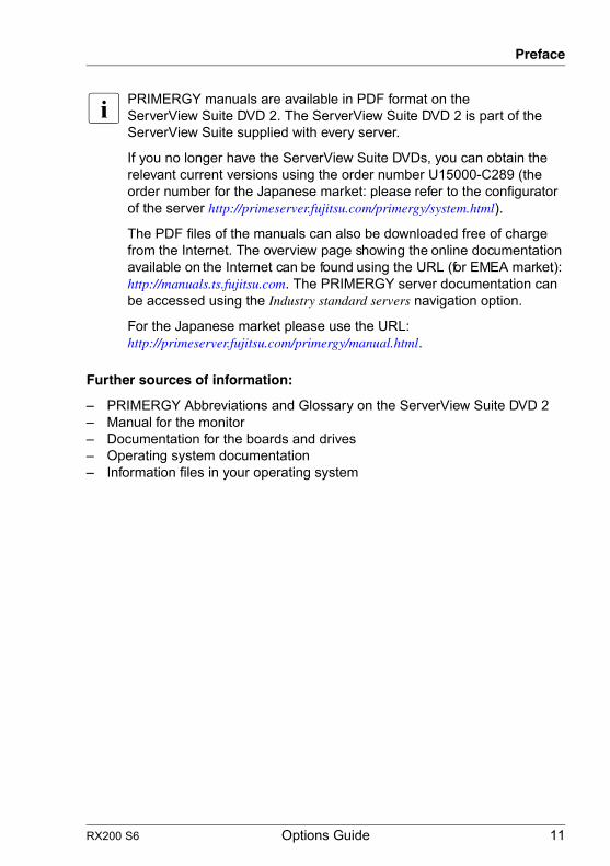
I PRIMERGY manuals are available in PDF format on the ServerView Suite DVD 2. The ServerView Suite DVD 2 is part of the ServerView Suite supplied with every server.
If you no longer have the ServerView Suite DVDs, you can obtain the relevant current versions using the order number U15000-C289 (the order number for the Japanese market: please refer to the configurator of the server http://primeserver.fujitsu.com/primergy/system.html).
The PDF files of the manuals can also be downloaded free of charge from the Internet. The overview page showing the online documentation available on the Internet can be found using the URL (for EMEA market): http://manuals.ts.fujitsu.com. The PRIMERGY server documentation can be accessed using the Industry standard servers navigation option.
For the Japanese market please use the URL: http://primeserver.fujitsu.com/primergy/manual.html.
Further sources of information:
– PRIMERGY Abbreviations and Glossary on the ServerView Suite DVD 2– Manual for the monitor– Documentation for the boards and drives– Operating system documentation– Information files in your operating system

12 Options Guide RX200 S6
Preface
1.3 Expansions and conversions
Main memory
The system board offers 12 slots for memory modules. 6 memory slots can be used in mono processor configurations.
Second processor
The system board can be upgraded with a second processor. Only processors of the same type may be used on the system board. The second processor must have the same clock frequency as the first.
Accessible drive
In the version with a maximum of six HDD modules, a 5.25 inch bay is available for a DVD drive (SATA interface) with a height of 0.5 inches.
HDD modules
The server can accommodate two further HDD modules instead of the DVD drive. To do this, you must install a conversion kit consisting of an additional HDD cage and a HDD backplane for up to 8 HDD modules.
I The conversion kit is only available for the EMEA market.
Expansion cards in the PCI Express slots
The system board offers two slots with a PCI Express x8 interface and one slot with a PCI Express x4 interface (exclusively for modular RAID controllers):
Expansion cards can only be installed using three-slot riser cards. The riser cards provide three slots at a right angle to the system board (two slots for PCIe controllers and one slot for a RAID controller).
Intelligent Battery Backup Unit
You can add an iBBU (intelligent Battery Backup Unit) to the optional modular RAID controller to ensure data integrity in the event of a power failure.
RX200 S6 Options Guide 13
Preface
Trusted Platform Module (TPM)
A Trusted Platform Module (TPM) for safer storage of keys can be implemented as an option. This module enables programs from third party manufacturers to store key information (e.g. drive encryption using Windows Bitlocker Drive Encryption).
The TPM is activated via the BIOS system (for more information, refer to the “D3031 BIOS Setup Utility for RX200 S6" manual).
V CAUTION!
– When using the TPM, note the program descriptions provided by the third party manufacturers.
– You must also create a backup of the TPM content. To do this, follow the third party manufacturer's instructions. Without this backup, if the TPM or the system board is faulty you will not be able to access your data.
– If a failure occurs, please inform your service about the TPM activation before it takes any action, and be prepared to provide them with your backup copies of the TPM content.
USB Flash Module (UFM)
The server can be equipped with a USB Flash Module (UFM).
This module can be used as optional memory for software (e.g. VMware) or as a software dongle.

14 Options Guide RX200 S6
Preface
1.4 Notational conventions
The following notational conventions are used in this manual:
Text in italics indicates commands or menu items."Quotation marks" indicate names of chapters and terms that are being
emphasized.Ê describes activities that must be performed in the order
shown.V CAUTION! pay particular attention to texts marked with this symbol.
Failure to observe this warning may endanger your life, destroy the system or lead to the loss of data.
I indicates additional information, notes and tips.

RX200 S6 Options Guide 15
2 ProcedureV CAUTION!
● The actions described in this manual shall be performed by technical specialists. A technical specialist is a person who is trained to install the server including hardware and software.
● Repairs to the device that do not relate to CSS failures shall be performed by service personnel. Please note that unauthorized interference with the system will void the warranty and exempt the manufacturer from all liability.
● Any failure to observe the guidelines in this manual, and any improper repairs could expose the user to risks (electric shock, energy hazards, fire hazards) or damage the equipment.
Ê First of all, carefully read the safety instructions in the chapter "Safety instructions" on page 17.
Ê Make sure that all necessary manuals (see the section "Documentation overview" on page 10) are available; print the PDF files if required. Most importantly, you will need the Operating Manual for the server and the Technical Manual for the system board.
Ê Shut the server down correctly, switch it off, disconnect the power cords and open the server as described in the chapter "Preparation" on page 25.
Ê Carry out the expansion or upgrade of your server as described in the pertinent chapter.
I Installation and removal of the hot-plug components are described in the Operating Manual.
Ê Close the server, connect it to the power outlet, and switch it on as described in the chapter "Completion" on page 73.
Ê Start the operating system and make the appropriate configuration if necessary (see the Operating Manual).
I For the latest information on optional products provided for the RX200 S6 see the configurator of the server: https://sp.ts.fujitsu.com/dmsp/docs/cnfgrx200s6.pdf(for the EMEA market)http://primeserver.fujitsu.com/primergy/system.html (for the Japanese market)

16 Options Guide RX200 S6

RX200 S6 Options Guide 17
3 Safety instructionsI The following safety instructions are also provided in the manual "Safety
Notes and Regulations".
This device meets the relevant safety regulations for IT equipment. If you have any questions about whether you can install the server in the intended environment, please contact your sales outlet or our customer service team.
V CAUTION!
● The actions described in this manual shall be performed by technical specialists. A technical specialist is a person who is trained to install the server including hardware and software.
● Repairs to the device that do not relate to CSS failures shall be performed by service personnel. Please note that unauthorized interference with the system will void the warranty and exempt the manufacturer from all liability.
● Any failure to observe the guidelines in this manual, and any improper repairs could expose the user to risks (electric shock, energy hazards, fire hazards) or damage the equipment.
● Before installing/removing internal options to/from the server, turn off the server, all peripheral devices, and any other connected devices. Also unplug all power cords from the power outlet. Failure to do so can cause electric shock.

18 Options Guide RX200 S6
Safety instructions
Before starting up
V CAUTION!
● During installation and before operating the device, observe the instructions on environmental conditions for your device.
● If the device is brought in from a cold environment, condensation may form both inside and on the outside of the device.
Wait until the device has acclimatized to room temperature and is absolutely dry before starting it up. Material damage may be caused to the device if this requirement is not observed.
● Transport the device only in the original packaging or in packaging that protects it from knocks and jolts.
Installation and operation
V CAUTION!
● This unit should not be operated in ambient temperatures above 35 °C.
● If the unit is integrated into an installation that draws power from an industrial power supply network with an IEC309 connector, the power supply's fuse protection must comply with the requirements for non-industrial power supply networks for type A connectors.
● The unit automatically adjusts itself to a mains voltage in a range of 100V - 127V / 200V - 240V. Ensure that the local mains voltage lies within these limits.
● This device must only be connected to properly grounded power outlets or insulated sockets of the rack's internal power supply with tested and approved power cords.
● Ensure that the device is connected to a properly grounded power outlet close to the device.

RX200 S6 Options Guide 19
Safety instructions
V CAUTION!
● Ensure that the power sockets on the device and the properly grounded power outlets are freely accessible.
● The On/Off button or the main power switch (if present) does not isolate the device from the mains power supply. To disconnect it completely from the mains power supply, unplug all network power plugs from the properly grounded power outlets.
● Always connect the server and the attached peripherals to the same power circuit. Otherwise you run the risk of losing data if, for example, the server is still running but a peripheral device (e.g. memory subsystem) fails during a power outage.
● Data cables must be adequately shielded.
● Ethernet cabling has to comply with EN 50173 and EN 50174-1/2 standards or ISO/IEC 11801 standard respectively. The minimum requirement is a Category 5 shielded cable for 10/100 Ethernet, or a Category 5e cable for Gigabit Ethernet.
● Route the cables in such a way that they do not create a potential hazard (make sure no-one can trip over them) and that they cannot be damaged. When connecting the server, refer to the relevant instructions in this manual.
● Never connect or disconnect data transmission lines during a storm (risk of lightning hazard).
● Make sure that no objects (e.g. jewelry, paperclips etc.) or liquids can get inside the server (risk of electric shock, short circuit).
● In emergencies (e.g. damaged casing, controls or cables, penetration of liquids or foreign bodies), switch off the server immediately, remove all power plugs and contact your sales outlet or customer service team.

20 Options Guide RX200 S6
Safety instructions
V CAUTION!
● Proper operation of the system (in accordance with IEC 60950-1/2 resp. EN 60950-1/2) is only ensured if the casing is completely assembled and the rear covers for the installation slots have been fitted (electric shock, cooling, fire protection, interference suppression).
● Only install system expansions that satisfy the requirements and rules governing safety and electromagnetic compatibility and those relating to telecommunication terminals. If you install other expansions, they may damage the system or violate the safety regulations. Information on which system expansions are approved for installation can be obtained from our customer service center or your sales outlet.
● The components marked with a warning notice (e.g. lightning symbol) may only be opened, removed or exchanged by authorized, qualified personnel. Exception: CSS components can be replaced.
● The warranty is void if the server is damaged during installation or replacement of system expansions.
● Only set screen resolutions and refresh rates that are specified in the operating manual for the monitor. Otherwise, you may damage your monitor. If you are in any doubt, contact your sales outlet or customer service center.
● Before installing/removing internal options to/from the server, turn off the server, all peripheral devices, and any other connected devices. Also unplug all power cords from the outlet. Failure to do so can cause electric shock.
● Do not damage or modify internal cables or devices. Doing so may cause a device failure, fire, or electric shock.
● Devices inside the server remain hot after shutdown. Wait for a while after shutdown before installing or removing internal options.
● The circuit boards and soldered parts of internal options are exposed and can be damaged by static electricity. Before handling them, first touch a metal part of the server to discharge static electricity from your body.
● Do not touch the circuitry on boards or soldered parts. Hold the metallic areas or the edges of the circuit boards.
RX200 S6 Options Guide 21
Safety instructions
V CAUTION!
● Install the screw removed during installation/detaching Internal Options in former device/position. To use a screw of the different kind causes a breakdown of equipment.
● The installation indicated on this note is sometimes changed to the kind of possible options without notice.
Batteries
V CAUTION!
● Incorrect replacement of batteries may result in a risk of explosion. The batteries may only be replaced with identical batteries or with a type recommended by the manufacturer (see the Technical Manual for the system board).
● Replace the lithium battery on the system board in accordance with the instructions in the Technical Manual for the system board.

22 Options Guide RX200 S6
Safety instructions
Working with CDs/DVDs/BDs and optical drives
When working with devices with optical drives, these instructions must be followed.
V CAUTION!
● Only use CDs/DVDs/BDs that are in perfect condition, in order to prevent data loss, equipment damage and injury.
● Check each CD/DVD/BD for damage, cracks, breakages etc. before inserting it in the drive.
Note that any additional labels applied may change the mechanical properties of a CD/DVD/BD and cause imbalance.
Damaged and imbalanced CDs/DVDs/BDs can break at high drive speeds (data loss).
Under certain circumstances, sharp CD/DVD/BD fragments can pierce the cover of the optical drive (equipment damage) and can fly out of the device (danger of injury, particularly to uncovered body parts such as the face or neck).
● High humidity and airborne dust levels are to be avoided. Electric shocks and/or server failures may be caused by liquids such as water, or metallic items, such as paper clips, entering a drive.
● Shocks and vibrations are also to be avoided.
● Do not insert any objects other than the specified CDs/DVDs/BDs.
● Do not pull on, press hard, or otherwise handle the CD/DVD/BD tray roughly.
● Do not disassemble the optical drive.
● Before use, clean the optical disk tray using a soft, dry cloth.
● As a precaution, remove disks from the optical drive when the drive is not to be used for a long time. Keep the optical disk tray closed to prevent foreign matter, such as dust, from entering the optical drive.
● Hold CDs/DVDs/BDs by their edges to avoid contact with the disk surface.

RX200 S6 Options Guide 23
Safety instructions
● Do not contaminate the CD/DVD/BD surface with fingerprints, oil, dust, etc. If dirty, clean with a soft, dry cloth, wiping from the center to the edge. Do not use benzene, thinners, water, record sprays, antistatic agents, or silicone-impregnated cloth.
● Be careful not to damage the CD/DVD/BD surface.
● Keep the CDs/DVDs/BDs away from heat sources.
● Do not bend or place heavy objects on CDs/DVDs/BDs.
● Do not write with ballpoint pen or pencil on the label (printed) side.
● Do not attach stickers or similar to the label side. Doing so may cause rotational eccentricity and abnormal vibrations.
● When a CD/DVD/BD is moved from a cold place to a warm place, moisture condensation on the CD/DVD/BD surface can cause data read errors. In this case, wipe the CD/DVD/BD with a soft, dry cloth then let it air dry. Do not dry the CD/DVD/BD using devices such as a hair dryer.
● To avoid dust, damage, and deformation, keep the CD/DVD/BD in its case whenever it is not in use.
● Do not store CDs/DVDs/BDs at high temperatures. Areas exposed to prolonged direct sunlight or near heating appliances are to be avoided.
I You can prevent damage from the optical drive and the CDs/DVDs/BDs, as well as premature wear of the disks, by observing the following suggestions:
– Only insert disks in the drive when needed and remove them after use.
– Store the disks in suitable sleeves.– Protect the disks from exposure to heat and direct sunlight.
Laser information
The optical drive complies with IEC 60825-1 laser class 1.
V CAUTION!
The optical drive contains a light-emitting diode (LED), which under certain circumstances produces a laser beam stronger than laser class 1. Looking directly at this beam is dangerous.
Never remove parts of the optical drive casing!

24 Options Guide RX200 S6
Safety instructions
Modules with electrostatic-sensitive components
Systems and components that might be damaged by electrostatic discharge (ESD) are marked with the following label:
Figure 1: ESD label
When you handle components fitted with ESDs, you must observe the following points under all circumstances:
● Remove the power plug before installing or removing components containing ESDs.
● You must always discharge yourself of static charges (e.g. by touching a grounded object) before working.
● The equipment and tools you use must be free of static charges.
● Only touch the components at the positions highlighted in green (touch points).
● Do not touch any exposed pins or conductors on a component.
● Use a grounding cable designed for this purpose to connect yourself to the system unit as you install components.
● Place all components on a static-safe base.
I You will find a detailed description for handling ESD components in the relevant European or international standards (DIN EN 61340-5-1, ANSI/ESD S20.20).

RX200 S6 Options Guide 25
4 PreparationV CAUTION!
● Before removing or attaching covers, turn off the server, all peripheral devices, and any other connected devices. Also unplug all power cords from the power outlet. Failure to do so can cause electric shock.
● Only for rack model:Use the anti-tilt plate to prevent the rack from tipping when installing the rack. Pulling the server out of the rack without having installed the anti-tilt plate may cause the rack to tip over.
● Only for rack model:Be careful not to pinch fingers or clothes when sliding out the server or pushing it back. Failure to do so may cause injury.
● Before attaching the cover, make sure no unnecessary parts or tools are left inside the server.
● Before turning on the server, make sure the cover is closed.
● Follow the safety instructions in the chapter "Safety instructions" on page 17.
26 Options Guide RX200 S6
Preparation
4.1 Pulling the server out of the rack
Ê Terminate all applications and shut down the server correctly.
Ê If your operating system has not switched off the server, press the On/Off button.
Ê Pull all power cords out of the power outlet.
Ê Loosen the two knurled screws and pull the server carefully out of the rack as far as it will go.
I If the server is not easily accessible once it has been pulled out, remove it from the rack completely. See the Operating Manual for details on how to remove the server from the rack.
V CAUTION!
At least two people are needed to remove the server from the rack.(For the Japanese market, please refer to "安全上の注意およびその他の重要情報 ".)
RX200 S6 Options Guide 27
Preparation
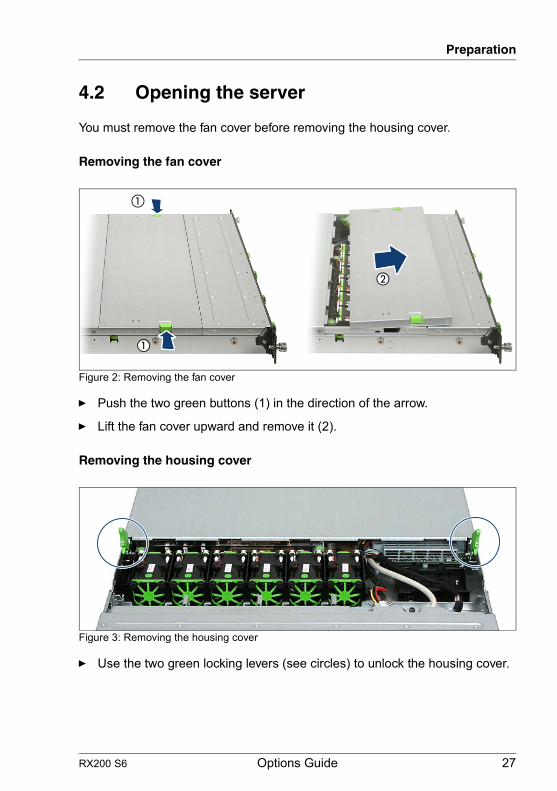
4.2 Opening the server
You must remove the fan cover before removing the housing cover.
Removing the fan cover
Figure 2: Removing the fan cover
Ê Push the two green buttons (1) in the direction of the arrow.
Ê Lift the fan cover upward and remove it (2).
Removing the housing cover
Figure 3: Removing the housing cover
Ê Use the two green locking levers (see circles) to unlock the housing cover.
�
�
�
28 Options Guide RX200 S6
Preparation
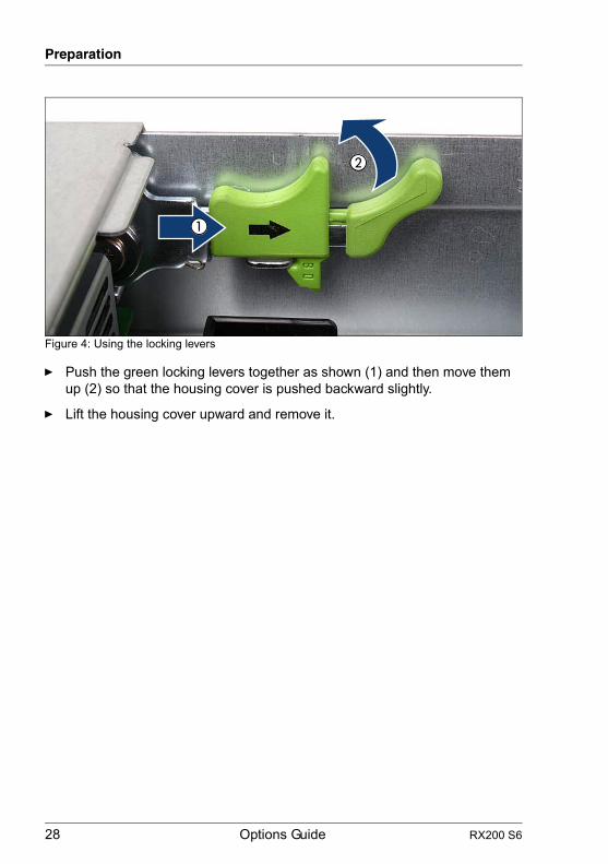
Figure 4: Using the locking levers
Ê Push the green locking levers together as shown (1) and then move them up (2) so that the housing cover is pushed backward slightly.
Ê Lift the housing cover upward and remove it.
RX200 S6 Options Guide 29
Preparation
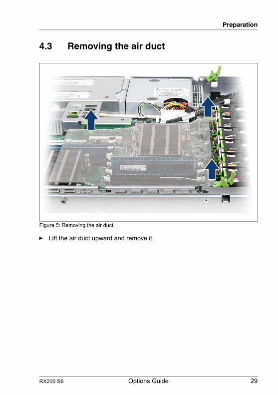
4.3 Removing the air duct
Figure 5: Removing the air duct
Ê Lift the air duct upward and remove it.

30 Options Guide RX200 S6
Preparation
RX200 S6 Options Guide 31
5 Main memoryV CAUTION!
● Before installing/removing memory to/from the server, turn off the server, all peripheral devices, and any other connected devices. Also unplug all power cords from the power outlet. Failure to do so can cause electric shock.
● A memory module consists of parts that are very vulnerable to damage by static electricity, and can easily be damaged by static electricity in the human body. Before handling memory modules, first touch a metal part of the server to discharge static electricity.
● Do not touch the circuitry on boards and soldered parts. Hold the metallic areas or the edge of the circuit boards.
● Do not install unauthorized third party memory modules. Doing so may cause electric shock, a fire, or failures.
● Wait for a sufficient period of time after server shutdown before installing or removing memory modules. Failure to do so may cause burns. When installing or removing memory modules, make sure to remove the screws at the specified points only. Failure to do so may cause injury. It may also cause failures.
● Touch only the specified part of the printed circuit board. Failure to do so may cause injury. It may also cause failures.
● Do not insert and remove memory modules repeatedly. Doing so may cause failures.
● If the memory module has not been correctly inserted, it may cause a fire. Insert the memory module with attention to its direction.
● If a memory module is installed and you pull the securing clips strongly outward, the memory module pops up. Doing so may cause a device failure.
● Follow the safety instructions in the chapter "Safety instructions" on page 17.

32 Options Guide RX200 S6
Main memory
5.1 Memory modules
The 12 slots (6 for each CPU) for main memory are designed for RDIMM (registered DIMM, capacities: 2, 4, 8 and 16 GB) as well as for UDIMM (unbuffered DIMM, capacity 2 GB) memory modules. The maximum main memory is for installing UDIMM memory modules 24 GB (12x 2 GB), for installing RDIMM memory modules 192 GB (12x 16 GB). Mixing both types of memory modules is not supported and leads to an error message.
When using Westmere-EP processors LV-DIMMs (low voltage DIMMs) can be used.
There are three modes of operation for the main memory:
– Independent Channel Mode / Performance Mode (recommended)– Mirrored Channel Mode– Spare Channel Mode
Depending on the mode of operation there are different population requirements.
I The types of memory modules and the modes of operation are described in the Technical Manual or in the configurator of the server.
I The current configurator can be found under:
http://ts.fujitsu.com/products/standard_servers/rack/primergy_rx200s6.html(for the EMEA market)
http://primeserver.fujitsu.com/primergy/system.html (for the Japanese market)
Notes on equipping
– Equipping always starts at DIMM slot 1A.
– The minimum memory configuration is 1 DIMM per system board in Independent Channel Mode.
– Memory modules with different clock rates may be mixed. The system automatically adjusts itself to the lowest clock rate.
– Single and dual and quad rank memory modules may be mixed.
– Install the memory module with the highest number of ranks into the slot with the lowest number (e.g. modul typ 4GB 2Rx4 into slot DIMM1A and modul typ 4GB 1Rx4 in slot DIMM2A).
RX200 S6 Options Guide 33
Main memory
– In the case of same number of ranks install the memory module with the highest capacity into the slot with lowest number (e.g. 8GB 2Rx4 modules (DIMM-1A) before 4GB 2Rx4 modules (DIMM-2A)).
– In Mirrored Channel Mode and in Spare Channel Mode, memory modules of different capacities may be mixed on a bank by bank basis.
– The assignment of the DIMM slots to the memory banks and channels is imprinted on the system board next to the DIMM slots.
5.2 Expanding the main memory
Ê Open the server as described in the chapter "Preparation" on page 25.
Ê Remove the air duct as described in the section "Removing the air duct" on page 29.
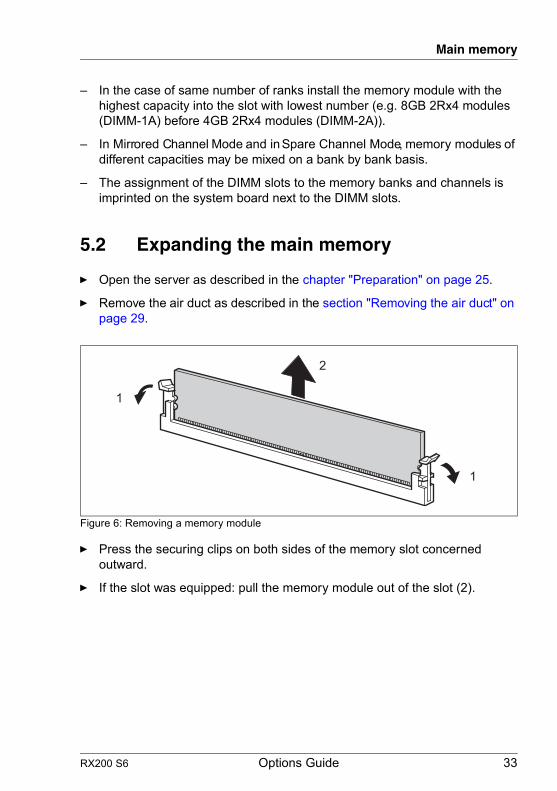
Figure 6: Removing a memory module
Ê Press the securing clips on both sides of the memory slot concerned outward.
Ê If the slot was equipped: pull the memory module out of the slot (2).
1
1
2

34 Options Guide RX200 S6
Main memory
Figure 7: Installing a memory module
Ê Carefully press the memory module into the slot (1) until the securing clips on both sides of it engage (2).
Ê Reinstall the air duct as described in the section "Installing the air duct" on page 73.
Ê Close the server, connect it to the power outlet, and switch it on as described in the chapter "Completion" on page 73.
2
2
1

RX200 S6 Options Guide 35
6 ProcessorsV CAUTION!
● Before installing/removing processors to/from the server, turn off the server, all peripheral devices, and any other connected devices. Also unplug all power cords from the power outlet. Failure to do so can cause electric shock.
● Do not touch the circuitry on boards and soldered parts. Hold the metallic areas or the edge of the circuit boards.
● When adding a processor, be sure to add memory into "DIMM 1D" additionally. Refer to chapter "Main memory" on page 31 for the installation of the memory.
● When installing the processor, be careful not to bend the pins of the processor socket.
● Follow the safety instructions in the chapter "Safety instructions" on page 17.
V CAUTION!
Processors are modules which can react extremely sensitively to electrostatic discharges and which must therefore always be handled with care. After a processor has been removed from its protective sleeve or from its socket, place it with its smooth side down on a non-conducting, antistatic surface. Never push a processor over a surface.

36 Options Guide RX200 S6
Processors
6.1 Installing a second processor
The system board can be upgraded with a second processor. The upgrade kit consists of a processor and a heat sink.
V CAUTION!
Only processors of the same type may be used on the system board. That means the number of the internal processor cores as well as the primary clock and the FSB frequency have to be the same. For dual operation, use a suitable multiprocessor operating system.
Ê Open the server as described in the chapter "Preparation" on page 25.
Ê Remove the air duct as described in the section "Removing the air duct" on page 29.
Figure 8: Opening the processor holder and removing the socket cover
Ê Press the spring clip downward and outward.
Ê Fold back the spring clip (1).
Ê Fold back the processor holder (2).
Ê Hold the socket cover by the two grips between your thumb and index finger and lift it vertically upward (3).
1
2
3

RX200 S6 Options Guide 37
Processors
Figure 9: Inserting and locking the processor
Ê Hold the processor between your thumb and index finger and align it at the socket coding (see circle).
V CAUTION!
The processor can only be installed in one particular direction.
Ê Place the processor in the socket with great care (1).
V CAUTION!
Do not bend the spring contacts of the processor socket. Never touch the underside of the processor. Even light contaminants, such as oil from human skin, can destroy the processor or impair its functionality.
Ê Close the processor holder (2).
Ê Lock the processor in the socket by returning the spring clip to its original position (3).
1
2
3
38 Options Guide RX200 S6
Processors
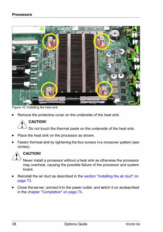
Figure 10: Installing the heat sink
Ê Remove the protective cover on the underside of the heat sink.
V CAUTION!
Do not touch the thermal paste on the underside of the heat sink.
Ê Place the heat sink on the processor as shown.
Ê Fasten the heat sink by tightening the four screws in a crossover pattern (see circles).
V CAUTION!
Never install a processor without a heat sink as otherwise the processor may overheat, causing the possible failure of the processor and system board.
Ê Reinstall the air duct as described in the section "Installing the air duct" on page 73.
Ê Close the server, connect it to the power outlet, and switch it on as described in the chapter "Completion" on page 73.

RX200 S6 Options Guide 39
Processors
6.2 Replacing the processor
V CAUTION!
Only processors of the same type may be used on the system board. That means the number of the internal processor cores as well as the primary clock and the FSB frequency have to be the same. For dual operation, use a suitable multiprocessor operating system.
Ê Open the server as described in the chapter "Preparation" on page 25.
Ê Remove the air duct as described in the section "Removing the air duct" on page 29.
Figure 11: Removing the heat sink
Ê Loosen the four screws of the heat sink in a crossover pattern.
Ê Loosen the heat sink carefully by turning it back and forth. Then lift it up and off.
Ê Remove the residual thermal paste from the underside of the heat sink.
Ê Clean the underside of the heat sink using a lint-free cloth.

40 Options Guide RX200 S6
Processors
Figure 12: Removing an old processor
Ê Press the spring clip downward and outward.
Ê Fold back the spring clip (1).
Ê Fold back the processor holder (2).
Ê Lift the installed processor carefully out of the socket (3).
V CAUTION!
Do not bend the spring contacts of the processor socket.
Figure 13: Inserting and locking a new processor
Ê Hold the new processor between your thumb and index finger and align it at the socket coding (see circle).
V CAUTION!
The processor can only be installed in one particular direction.
Ê Place the new processor in the socket with great care (1).
V CAUTION!
Do not bend the spring contacts of the processor socket. Never touch the underside of the processor. Even light contaminants, such as oil from human skin, can destroy the processor or impair its functionality.
1
2
3
1
2
3

RX200 S6 Options Guide 41
Processors
Ê Close the processor holder (2).
Ê Lock the processor in the socket by returning the spring clip to its original position (3).
Ê Apply a small amount of thermal paste to the upper side of the new processor.
Ê Ensure a thin and even distribution of the thermal paste.
Ê Place the heat sink on the processor (see figure 10 on page 38).
Ê Fasten the heat sink by tightening the four screws in a crossover pattern.
Ê Reinstall the air duct as described in the chapter "Completion" on page 73.
Ê Close the server, connect it to the power outlet, and switch it on as described in the chapter "Completion" on page 73.

42 Options Guide RX200 S6
Processors
6.3 Replacing the heat sink
Ê Open the server as described in the chapter "Preparation" on page 25.
Ê Remove the air duct as described in the section "Removing the air duct" on page 29.
Ê Remove the four screws of the heat sink in a crossover pattern (see figure 11 on page 39).
Ê Loosen the heat sink carefully by turning it back and forth. Then lift it up and off.
Ê Clean the upper side of the processor using a lint-free cloth.
I New heat sinks come with thermal paste already applied. When reusing used heat sinks, you need to apply thermal paste.
Ê Place the heat sink on the processor (see figure 10 on page 38).
Ê Fasten the heat sink by tightening the four screws in a crossover pattern (see figure 10 on page 38).
Ê Reinstall the air duct as described in the section "Installing the air duct" on page 73.
Ê Close the server, connect it to the power outlet, and switch it on as described in the chapter "Completion" on page 73.
RX200 S6 Options Guide 43
7 Accessible driveV CAUTION!
● Before installing/removing an accessible drive to/from the server, turn off the server, all peripheral devices, and any other connected devices. Also unplug all power cords from the power outlet. Failure to do so can cause electric shock.
● When installing an accessible drive, hold it by the side. Applying force to the top may cause failures.
● Do not touch the circuitry on boards and soldered parts. Hold the metallic areas or the edge of the circuit boards.
● The circuit boards and soldered parts of internal options are exposed and can be damaged by static electricity. Before handling them, first touch a metal part on the server to discharge static electricity from your body.
● Before installing an internal accessible drive, see the manual for the accessible drive.
● When forcing an accessible drive into a server, be careful so as not to pinch the cable etc. connected to an accessible drive.
● Follow the safety instructions in the chapter "Safety instructions" on page 17.
44 Options Guide RX200 S6
Accessible drive
7.1 Installing a SATA DVD drive
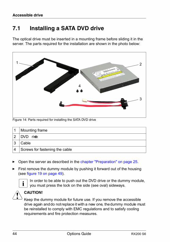
The optical drive must be inserted in a mounting frame before sliding it in the server. The parts required for the installation are shown in the photo below:
Figure 14: Parts required for installing the SATA DVD drive
Ê Open the server as described in the chapter "Preparation" on page 25.
Ê First remove the dummy module by pushing it forward out of the housing (see figure 19 on page 49).
I In order to be able to push out the DVD drive or the dummy module, you must press the lock on the side (see oval) sideways.
V CAUTION!
Keep the dummy module for future use. If you remove the accessible drive again and do not replace it with a new one, the dummy module must be reinstalled to comply with EMC regulations and to satisfy cooling requirements and fire protection measures.
1 Mounting frame2 DVD drive3 Cable4 Screws for fastening the cable
12
3
4

RX200 S6 Options Guide 45
Accessible drive
Figure 15: Connecting the DVD cable
Ê Connect the white connector of the DVD cable to the corresponding connector on the HDD backplane (see arrow).
Ê Connect the small black connector of the DVD cable to the connector SATA ODD on the system board (see the cabling plans in the Appendix).
Figure 16: Position of the pins in the mounting frame and the openings on the DVD drive
Ê Insert the DVD drive into the mounting frame so that the plastic pins (1) on both sides of the mounting frame are inserted into the openings (2) on the outsides of the drive.
1 2

46 Options Guide RX200 S6
Accessible drive
Figure 17: DVD drive ready to be installed
Ê Push the DVD drive into the slot from the outside until it engages.
Ê Connect the free black connector of the DVD cable to the DVD drive.
Ê Close the server, connect it to the power outlet, and switch it on as described in the chapter "Completion" on page 73.

RX200 S6 Options Guide 47
8 HDD modulesV CAUTION!
● Before installing/removing an HDD module to/from the server, turn off the server, all peripheral devices, and any other connected devices. Also unplug all power cords from the power outlet. Failure to do so can cause electric shock.
● When installing an HDD module, hold it by the side. Applying force to the top may cause failures.
● Do not touch the circuitry on boards and soldered parts. Hold the metallic areas or the edge of the circuit boards.
● The circuit boards and soldered parts of internal options are exposed and can be damaged by static electricity. Before handling them, first touch a metal part on the server to discharge static electricity from your body.
● Follow the safety instructions in the chapter "Safety instructions" on page 17.
48 Options Guide RX200 S6
HDD modules
8.1 Installing additional HDD cage
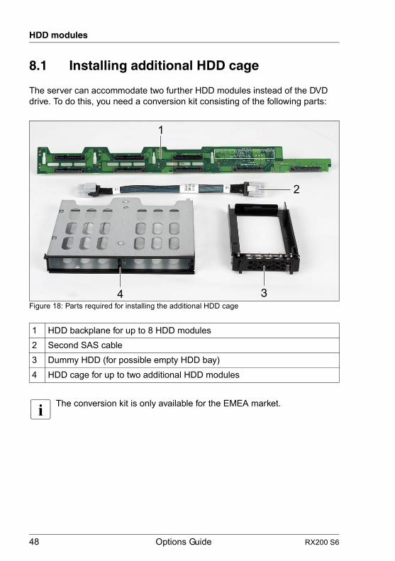
The server can accommodate two further HDD modules instead of the DVD drive. To do this, you need a conversion kit consisting of the following parts:
Figure 18: Parts required for installing the additional HDD cage
I The conversion kit is only available for the EMEA market.
1 HDD backplane for up to 8 HDD modules2 Second SAS cable3 Dummy HDD (for possible empty HDD bay)4 HDD cage for up to two additional HDD modules
4 3
2
1

RX200 S6 Options Guide 49
HDD modules
Ê Open the server as described in the chapter "Preparation" on page 25.
Removing an existing DVD drive or dummy module
Ê Disconnect the DVD cable from the system board and from the HDD backplane.
Figure 19: Removing the DVD drive or dummy module
Ê Remove the DVD drive or the dummy module by pushing it forward out of the housing.
I In order to be able to push out the DVD drive or the dummy module, you must press the lock on the side (see oval) sideways.
50 Options Guide RX200 S6
HDD modules
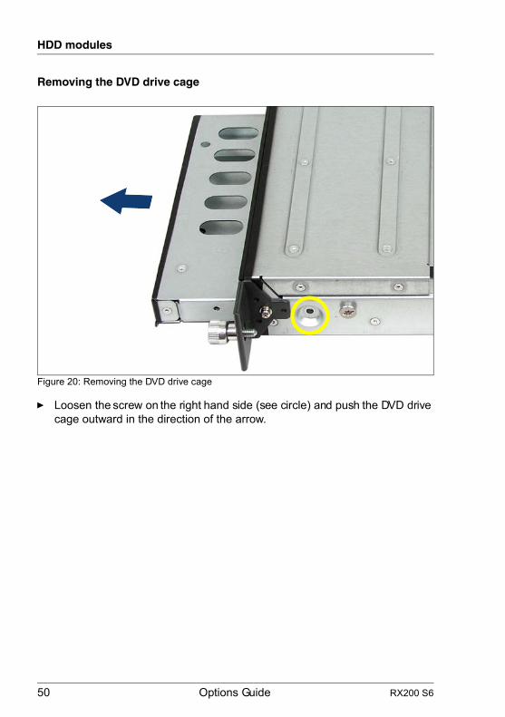
Removing the DVD drive cage
Figure 20: Removing the DVD drive cage
Ê Loosen the screw on the right hand side (see circle) and push the DVD drive cage outward in the direction of the arrow.

RX200 S6 Options Guide 51
HDD modules
Removing the existing HDD backplane (6x HDD)
Ê Remove all HDD modules from the housing.
Figure 21: Removing the HDD backplane
Ê Disconnect all cables from the HDD backplane (see circle).
Ê Lift the HDD backplane over the metal bars (see arrows) and then remove it.
Installing the new HDD backplane (8x HDD)
Ê Place the new HDD backplane (8x HDD) on the metal bars (see arrows in figure 21) and press the HDD backplane down carefully.
Ê Connect all the required cables to the HDD backplane (see figure "Cabling for up to 8 HDD modules with optional RAID controller" on page 80).
52 Options Guide RX200 S6
HDD modules
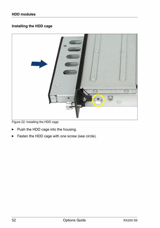
Installing the HDD cage
Figure 22: Installing the HDD cage
Ê Push the HDD cage into the housing.
Ê Fasten the HDD cage with one screw (see circle).

RX200 S6 Options Guide 53
HDD modules
Inserting the HDD modules
Figure 23: Installation positions of the additional HDD modules
Ê Push the additional HDD modules into the two bays (left side = HDD #6, right side = HDD #7) of the HDD cage (description see the Operating Manual).
Ê Close the server, connect it to the power outlet, and switch it on as described in the chapter "Completion" on page 73.
HDD #6 HDD #7

54 Options Guide RX200 S6
HDD modules

RX200 S6 Options Guide 55
9 Expansion cards and iBBUV CAUTION!
● Before installing/removing expansion cards to/from the server, turn off the server, all peripheral devices, and any other connected devices. Also unplug all power cables from the power outlet. Failure to do so can cause electric shock.
● The circuit boards and soldered parts of internal options are exposed and can be damaged by static electricity. Before handling them, first touch a metal part on the server to discharge static electricity from your body.
● Do not touch the circuitry on boards and soldered parts. Hold the metallic areas or the edge of the circuit boards.
● Follow the safety instructions in the chapter "Safety instructions" on page 17.

56 Options Guide RX200 S6
Expansion cards and iBBU
9.1 Installing an expansion card
The server has three slots for PCIe expansion cards. These are integrated in the system using riser cards (see positions (1) - (3) in figure 24).The individual slots can be equipped as follows:– Riser card #1: PCIe x8, standard and low-profile expansion cards– Riser card #2: PCIe x8, only low-profile expansion cards– Riser card #3: PCIe x4, internal, only for (low-profile) RAID controllers
I For the installing order see the configurator of the server: https://sp.ts.fujitsu.com/dmsp/docs/cnfgrx200s6.pdf(for the EMEA market)http://primeserver.fujitsu.com/primergy/system.html (for the Japanese market)
Removing the riser card holder
Ê Open the server as described in chapter "Preparation" on page 25.
Figure 24: Position of riser card holders 1-3
Ê If necessary, disconnect the cables from the relevant expansion card.
Ê Lift the required riser card holder upward and remove it.
2 3
1
RX200 S6 Options Guide 57
Expansion cards and iBBU
Installing an expansion card
Ê Please read the documentation supplied with the expansion card.
Ê Connect any required cables to the expansion card.
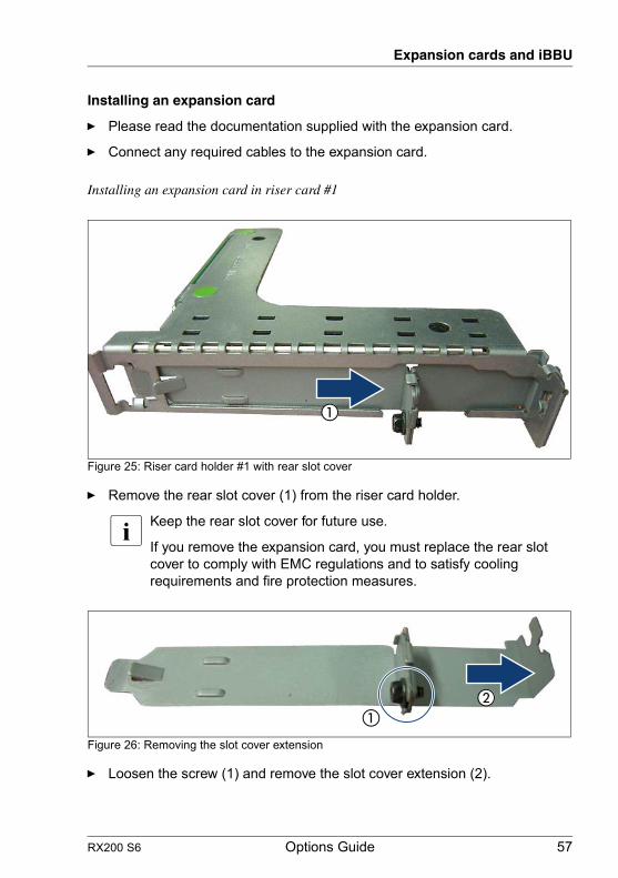
Installing an expansion card in riser card #1
Figure 25: Riser card holder #1 with rear slot cover
Ê Remove the rear slot cover (1) from the riser card holder.
I Keep the rear slot cover for future use.
If you remove the expansion card, you must replace the rear slot cover to comply with EMC regulations and to satisfy cooling requirements and fire protection measures.
Figure 26: Removing the slot cover extension
Ê Loosen the screw (1) and remove the slot cover extension (2).

58 Options Guide RX200 S6
Expansion cards and iBBU
Figure 27: Attaching the slot cover extension to the expansion card
Ê Attach the slot cover extension to the slot cover of the expansion card (1).
Ê Fasten the slot cover extension with one screw (2).
Figure 28: Riser card holder #1 equipped with an expansion card
Ê Insert the expansion card into the riser card #1.
I Make sure that the rear slot cover is positioned in the designated groove.
Ê If necessary, connect the cables to the expansion card and the other components.

RX200 S6 Options Guide 59
Expansion cards and iBBU
Installing an expansion card in riser card #2
Figure 29: Riser card holder #2 with riser card
Ê Remove the rear slot cover (1) from the riser card holder.
I Keep the rear slot cover for future use.
If you remove the expansion card, you must replace the rear slot cover to comply with EMC regulations and to satisfy cooling requirements and fire protection measures.
1

60 Options Guide RX200 S6
Expansion cards and iBBU
Figure 30: Riser card holder #2 equipped with an expansion card
Ê Insert the expansion card into the riser card of the same height.
I Make sure that the rear slot cover is positioned in the designated groove.
Ê If necessary, connect the cables to the expansion card and the other components.
Installing an expansion card in riser card #3
See section "Installing a modular RAID controller" on page 61.
Reinstalling the riser card holder
Ê Position the riser card holder over the relevant slot on the system board.
Ê Carefully push the riser card holder into the slot by pressing on the green points.
Ê Close the server, connect it to the power outlet, and switch it on as described in the chapter "Completion" on page 73.

RX200 S6 Options Guide 61
Expansion cards and iBBU
9.2 Installing a modular RAID controller
A modular RAID controller can be installed in the server as an option.Riser card #3 (see figure 24 on page 56) is intended solely for this purpose.
Removing riser card holder with riser card #3
Ê Lift the required riser card holder with riser card #3 upward and remove it.
Installing a modular RAID controller
Ê Please read the documentation supplied with the modular RAID controller.
Ê Connect any required cables to the modular RAID controller.
Figure 31: Installing the modular RAID controller in riser card #3
Ê Carefully push the modular RAID controller into the slot of riser card #3.
I Make sure that the modular RAID controller is positioned correctly (see circle).
Installing the riser card holder with riser card #3
Ê Position the riser card holder over the relevant slot on the system board.
Ê Carefully push the riser card holder into the slot by pressing on the green points.
Ê Close the server, connect it to the power outlet, and switch it on as described in the chapter "Completion" on page 73.

62 Options Guide RX200 S6
Expansion cards and iBBU
9.3 Installing an iBBU
V CAUTION!
● The iBBU (model 25034) used in this server may present a fire or chemical burn hazard if mistreated. Do not disassemble, heat about 100°C (212°F) or incinerate.
● If you remove the iBBU: Dispose of used iBBU properly. Keep away of children.
You can add an iBBU (intelligent Battery Backup Unit) to a modular RAID controller in riser card #3 or a RAID controller in riser card #2 or #1.
Figure 32: iBBU and cable
1 Cable from the iBBU to the RAID controller 2 iBBU
1
2
RX200 S6 Options Guide 63
Expansion cards and iBBU
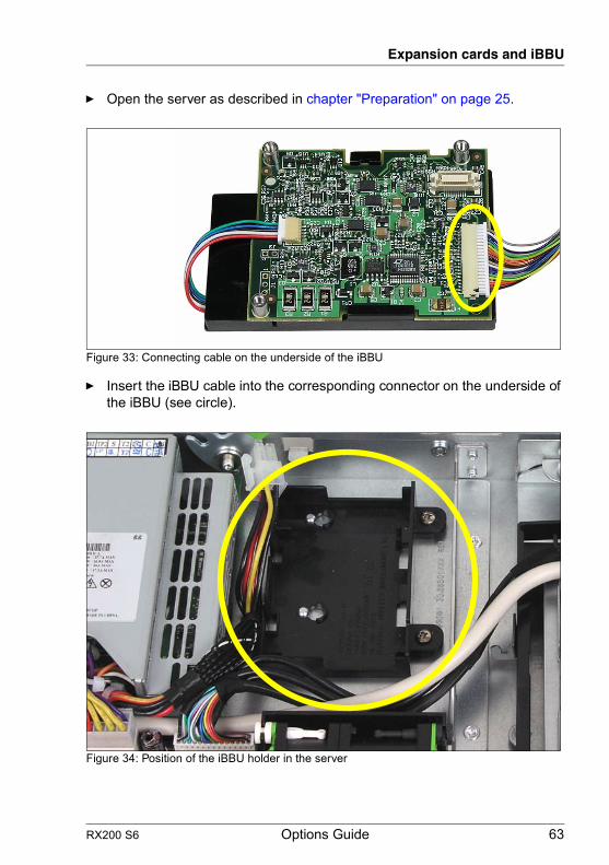
Ê Open the server as described in chapter "Preparation" on page 25.
Figure 33: Connecting cable on the underside of the iBBU
Ê Insert the iBBU cable into the corresponding connector on the underside of the iBBU (see circle).
Figure 34: Position of the iBBU holder in the server

64 Options Guide RX200 S6
Expansion cards and iBBU
Figure 35: Installing the iBBU
Ê Install the iBBU in its holder in the server as follows:
1. Push the iBBU under the two plastic pins of the iBBU holder (1).
2. Press down the iBBU on the opposite side until it clicks into place (2).
11
2
RX200 S6 Options Guide 65
Expansion cards and iBBU
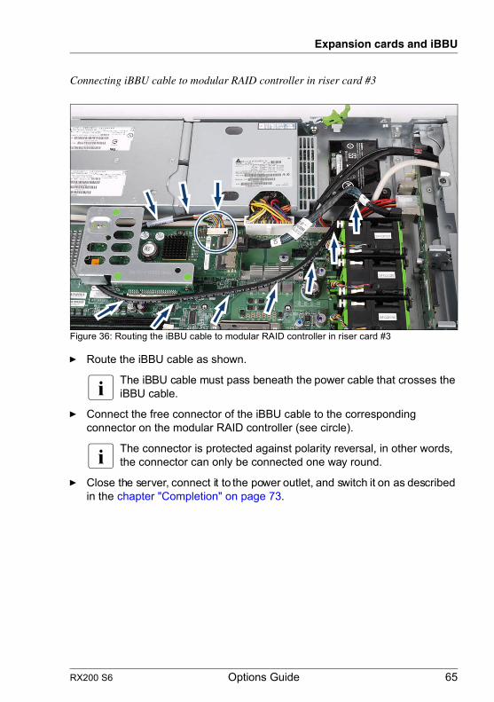
Connecting iBBU cable to modular RAID controller in riser card #3
Figure 36: Routing the iBBU cable to modular RAID controller in riser card #3
Ê Route the iBBU cable as shown.
I The iBBU cable must pass beneath the power cable that crosses the iBBU cable.
Ê Connect the free connector of the iBBU cable to the corresponding connector on the modular RAID controller (see circle).
I The connector is protected against polarity reversal, in other words, the connector can only be connected one way round.
Ê Close the server, connect it to the power outlet, and switch it on as described in the chapter "Completion" on page 73.
66 Options Guide RX200 S6
Expansion cards and iBBU
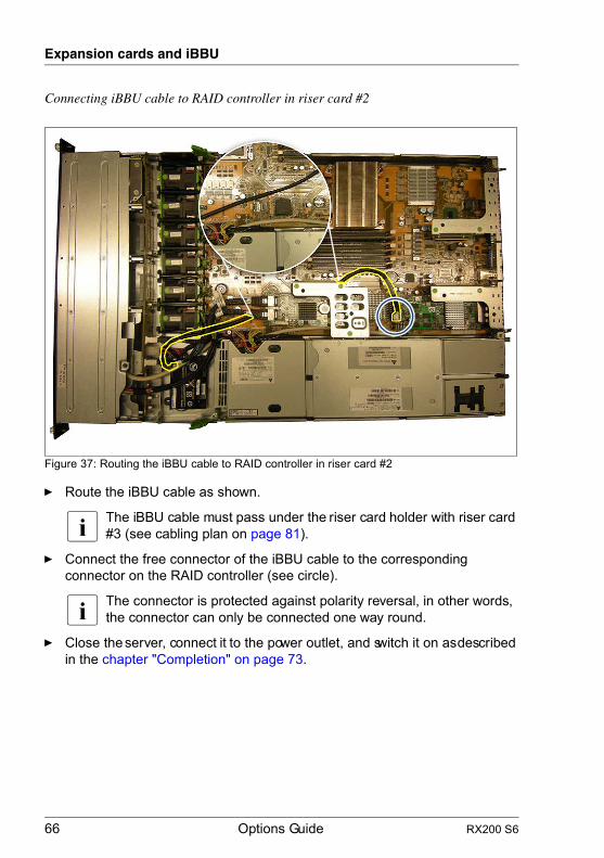
Connecting iBBU cable to RAID controller in riser card #2
Figure 37: Routing the iBBU cable to RAID controller in riser card #2
Ê Route the iBBU cable as shown.
I The iBBU cable must pass under the riser card holder with riser card #3 (see cabling plan on page 81).
Ê Connect the free connector of the iBBU cable to the corresponding connector on the RAID controller (see circle).
I The connector is protected against polarity reversal, in other words, the connector can only be connected one way round.
Ê Close the server, connect it to the power outlet, and switch it on as described in the chapter "Completion" on page 73.

RX200 S6 Options Guide 67
Expansion cards and iBBU
Connecting iBBU cable to RAID controller in riser card #1
Figure 38: Routing the iBBU cable to RAID controller in riser card #1
Ê Route the iBBU cable as shown.
I The iBBU cable must pass under the riser card holder with riser card #3 (see cabling plan on page 81).
Ê Connect the free connector of the iBBU cable to the corresponding connector on the RAID controller (see circle).
I The connector is protected against polarity reversal, in other words, the connector can only be connected one way round.
Ê Close the server, connect it to the power outlet, and switch it on as described in the chapter "Completion" on page 73.

68 Options Guide RX200 S6
Expansion cards and iBBU

RX200 S6 Options Guide 69
10 Further optionsV CAUTION!
Follow the safety instructions in the chapter "Safety instructions" on page 17.
10.1 Trusted Platform Module (TPM)
The Trusted Platform Module (TPM) is installed on the system board between riser card slots #1 and #2 (see photo below).
The server can be equipped with a TPM (Trusted Platform Module).
Figure 39: TPM installation kit
1 TPM (Trusted Platform Module) 3 Special screw for TPM2 TPM spacer 4 TPM screwdriver insert bit for
TPM special screw
� � � �
70 Options Guide RX200 S6
Further options
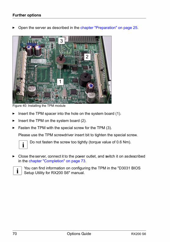
Ê Open the server as described in the chapter "Preparation" on page 25.
Figure 40: Installing the TPM module
Ê Insert the TPM spacer into the hole on the system board (1).
Ê Insert the TPM on the system board (2).
Ê Fasten the TPM with the special screw for the TPM (3).
Please use the TPM screwdriver insert bit to tighten the special screw.
I Do not fasten the screw too tightly (torque value of 0.6 Nm).
Ê Close the server, connect it to the power outlet, and switch it on as described in the chapter "Completion" on page 73.
I You can find information on configuring the TPM in the "D3031 BIOS Setup Utility for RX200 S6" manual.
1
2
31
2
3
RX200 S6 Options Guide 71
Further options
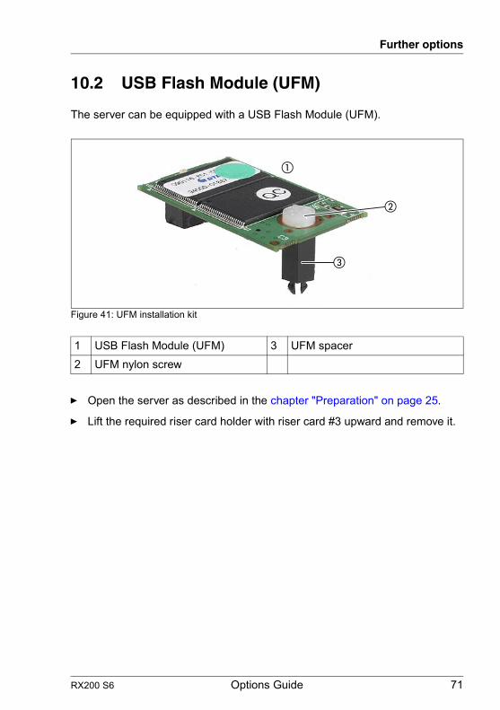
10.2 USB Flash Module (UFM)
The server can be equipped with a USB Flash Module (UFM).
Figure 41: UFM installation kit
Ê Open the server as described in the chapter "Preparation" on page 25.
Ê Lift the required riser card holder with riser card #3 upward and remove it.
1 USB Flash Module (UFM) 3 UFM spacer2 UFM nylon screw
72 Options Guide RX200 S6
Further options
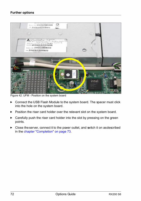
Figure 42: UFM - Position on the system board
Ê Connect the USB Flash Module to the system board. The spacer must click into the hole on the system board.
Ê Position the riser card holder over the relevant slot on the system board.
Ê Carefully push the riser card holder into the slot by pressing on the green points.
Ê Close the server, connect it to the power outlet, and switch it on as described in the chapter "Completion" on page 73.

RX200 S6 Options Guide 73
11 CompletionV CAUTION!
Follow the safety instructions in the chapter "Safety instructions" on page 17.
11.1 Installing the air duct
Figure 43: Installing the air duct
Ê Install the air duct. Please note the information shown in the following photos.

74 Options Guide RX200 S6
Completion
– The plastic pin of the air duct must fit into the groove of the system board (see circle).
Figure 44: Position of the plastic pin of the air duct
– The air duct must be hooked into the fan brackets on the left side and the right side as seen from the front (in this case, the right side):
Figure 45: Air duct (right side)
Slot #3
DIMM CPU #1
Fan #1/#2Fan #3/#4
RX200 S6 Options Guide 75
Completion
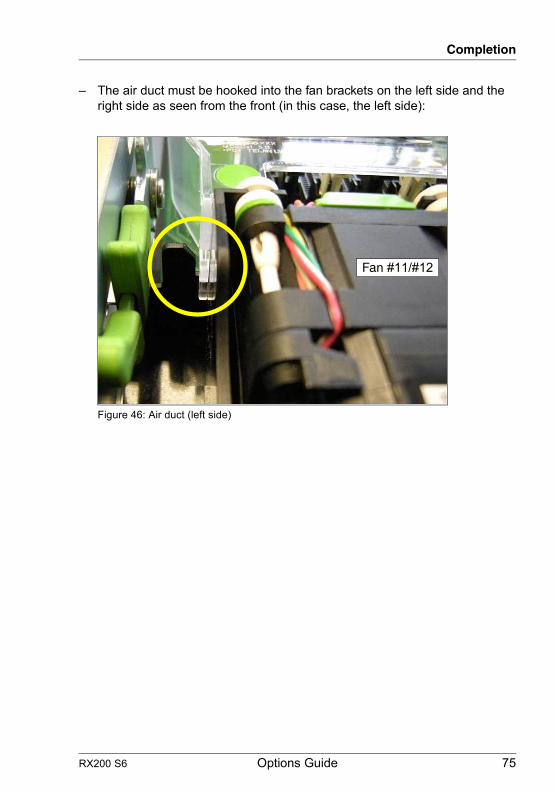
– The air duct must be hooked into the fan brackets on the left side and the right side as seen from the front (in this case, the left side):
Figure 46: Air duct (left side)
Fan #11/#12
76 Options Guide RX200 S6
Completion
11.2 Closing the server
Ê Position the housing cover so that it protrudes about 1 cm over the rear edge.
Make sure that each bolt is positioned in the corresponding nut.
Ê Push the housing cover forward until it clicks into place.
Ê Insert the fan cover.
Ê Insert the server into the rack (description see the Operating Manual).
V CAUTION!
At least two people are needed to position the server in the rack.(For the Japanese market, please refer to " 安全上の注意およびその他の重要情報 ".)
Ê Connect all power plugs to the power outlets and switch on the server.
RX200 S6 Options Guide 77
12 Appendix
12.1 Cabling
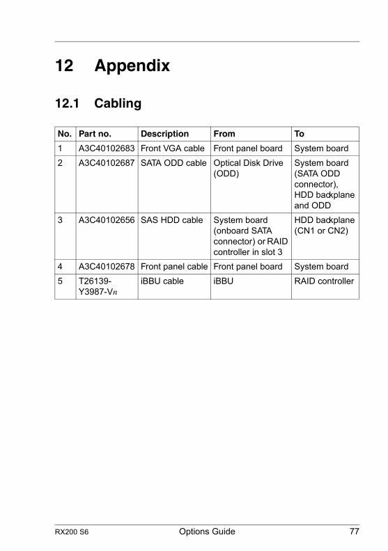
No. Part no. Description From To
1 A3C40102683 Front VGA cable Front panel board System board2 A3C40102687 SATA ODD cable Optical Disk Drive
(ODD)System board (SATA ODD connector), HDD backplane and ODD
3 A3C40102656 SAS HDD cable System board (onboard SATA connector) or RAID controller in slot 3
HDD backplane (CN1 or CN2)
4 A3C40102678 Front panel cable Front panel board System board5 T26139-
Y3987-VniBBU cable iBBU RAID controller

78 Options Guide RX200 S6
Appendix
Figure 47: Cabling for up to 4 HDD modules with onboard SATA controller
SA
TA
Pow
er
SA
SD
ata
Key:
Fro
nt-
pa
ne
l
CN3
VGA
PS
U 1
PS
U 2
Po
we
r
dis
trib
ution
bo
ard
P2
P3
P1
TP
M
Fro
nt V
GA
Slo
t 2
Slo
t 1
Fro
nt P
anel
CP
U 2
CP
U 1
SA
TA
OD
D
DIM
M 1
C
DIM
M 2
C
DIM
M 1
B
DIM
M 2
B
DIM
M 1
A
DIM
M 2
A
DIM
M 2
D
DIM
M 1
D
DIM
M 2
E
DIM
M 1
E
DIM
M 2
F
DIM
M 1
F
Fan
1/2
Fan
3/4
Fan
5/6
Fan
7/8
Fan
9/1
0
Fan
11/1
2
iRM
C
Ba
ck-
pla
ne
6x H
DD
DV
D d
rive
Slo
t 3
PW
RP
WR
CT
RL
Syste
m B
oa
rd
D3
03
1
CN
2
CN
1
SA
TA
1
uSS
D
14 2
3
RX200 S6 Options Guide 79
Appendix
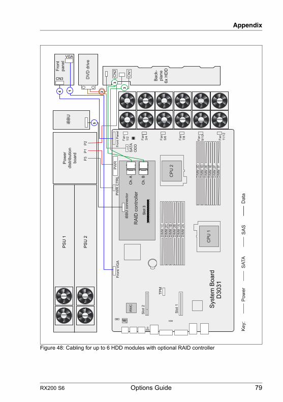
Figure 48: Cabling for up to 6 HDD modules with optional RAID controller
Fro
nt
pa
ne
l
CN3
VGA
iBB
U
PS
U 1
PS
U 2
P2
P3
P1
TP
M
Fro
nt V
GA
Slo
t 2
Slo
t 1
Fro
nt P
anel
CP
U 2
CP
U 1
SA
TA
OD
D
JP
5
DIM
M 1
C
DIM
M 2
C
DIM
M 1
B
DIM
M 2
B
DIM
M 1
A
DIM
M 2
A
DIM
M 2
D
DIM
M 1
D
DIM
M 2
E
DIM
M 1
E
DIM
M 2
F
DIM
M 1
F
Fan
1/2
Fan
3/4
Fan
5/6
Fan
7/8
Fan
9/1
0
Fan
11/1
2
iRM
C
DV
D d
rive
RA
ID c
ontr
oller
Slo
t 3
iBB
U c
onnecto
r
PW
RP
WR
CT
RL
Syste
m B
oa
rd
D3
03
1
CN
2
CN
1C
h. A
Ch. B
Ba
ck-
pla
ne
6x H
DD
Po
we
r
dis
trib
ution
bo
ard
SA
TA
Pow
er
SA
SD
ata
Key:
1
3
4
5
3
2
80 Options Guide RX200 S6
Appendix
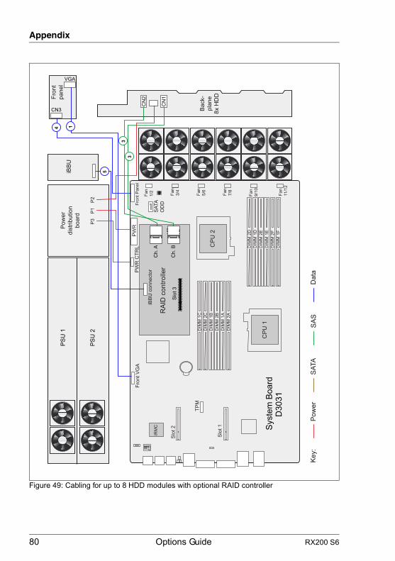
Figure 49: Cabling for up to 8 HDD modules with optional RAID controller
Fro
nt
pa
ne
l
CN3
VGA
iBB
U
PS
U 1
PS
U 2
P2
P3
P1
TP
M
Fro
nt V
GA
Slo
t 2
Slo
t 1
Fro
nt P
anel
CP
U 2
CP
U 1
SA
TA
OD
D
JP
5
DIM
M 1
C
DIM
M 2
C
DIM
M 1
B
DIM
M 2
B
DIM
M 1
A
DIM
M 2
A
DIM
M 2
D
DIM
M 1
D
DIM
M 2
E
DIM
M 1
E
DIM
M 2
F
DIM
M 1
F
Fan
1/2
Fan
3/4
Fan
5/6
Fan
7/8
Fan
9/1
0
Fan
11/1
2
iRM
C
RA
ID c
ontr
oller
Slo
t 3
iBB
U c
onnecto
r
PW
RP
WR
CT
RL
Syste
m B
oa
rd
D3
03
1
Ch. A
Ch. B
Ba
ck-
pla
ne
8x H
DD
CN
2
CN
1
SA
TA
Pow
er
SA
SD
ata
Key:
Po
we
r
dis
trib
ution
bo
ard
14
3
3
5

RX200 S6 Options Guide 81
Appendix
Figure 50: Cabling iBBU with optional RAID controller in riser card #2
Fro
nt
pa
ne
l
CN3
VGA
iBB
U
PS
U 1
PS
U 2
P2
P3
P1
TP
M
Fro
nt V
GA
Slo
t 2
Slo
t 1
Fro
nt P
anel
CP
U 2
CP
U 1
SA
TA
OD
D
JP
5
DIM
M 1
C
DIM
M 2
C
DIM
M 1
B
DIM
M 2
B
DIM
M 1
A
DIM
M 2
A
DIM
M 2
D
DIM
M 1
D
DIM
M 2
E
DIM
M 1
E
DIM
M 2
F
DIM
M 1
F
Fan
1/2
Fan
3/4
Fan
5/6
Fan
7/8
Fan
9/1
0
Fan
11/1
2
iRM
C
DV
D d
rive
RA
ID c
ontr
oller
Slo
t 3
iBB
U c
onnecto
r
PW
RP
WR
CT
RL
Syste
m B
oa
rd
D3
03
1
CN
2
CN
1C
h. A
Ch. B
Ba
ck-
pla
ne
6x H
DD
Po
we
r
dis
trib
ution
bo
ard
SA
TA
Pow
er
SA
SD
ata
Key:
1
3
4
3
2
RA
ID c
ontr
oller
Slo
t 2
iBB
U c
onnecto
r
5
82 Options Guide RX200 S6
Appendix
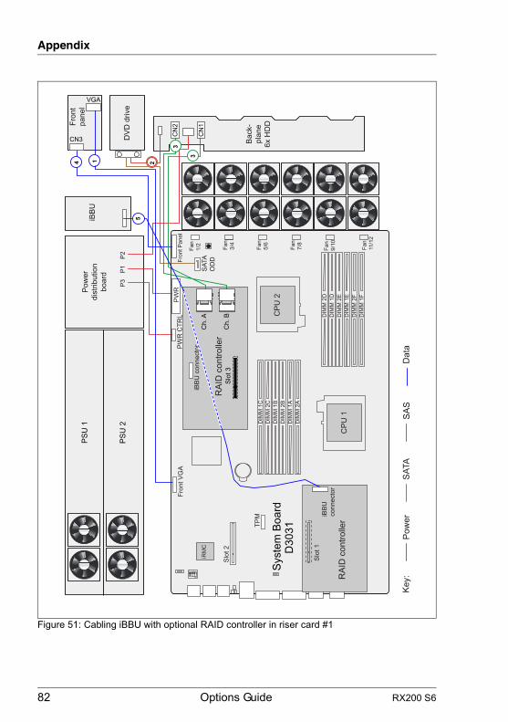
Figure 51: Cabling iBBU with optional RAID controller in riser card #1
Fro
nt
pa
ne
l
CN3
VGA
iBB
U
PS
U 1
PS
U 2
P2
P3
P1
TP
M
Fro
nt V
GA
Slo
t 2
Fro
nt P
anel
CP
U 2
CP
U 1
SA
TA
OD
D
JP
5
DIM
M 1
C
DIM
M 2
C
DIM
M 1
B
DIM
M 2
B
DIM
M 1
A
DIM
M 2
A
DIM
M 2
D
DIM
M 1
D
DIM
M 2
E
DIM
M 1
E
DIM
M 2
F
DIM
M 1
F
Fan
1/2
Fan
3/4
Fan
5/6
Fan
7/8
Fan
9/1
0
Fan
11/1
2
iRM
C
DV
D d
rive
RA
ID c
ontr
oller
Slo
t 3
iBB
U c
onnecto
r
PW
RP
WR
CT
RL
Syste
m B
oa
rd
D3
03
1
CN
2
CN
1C
h. A
Ch. B
Ba
ck-
pla
ne
6x H
DD
Po
we
r
dis
trib
ution
bo
ard
SA
TA
Pow
er
SA
SD
ata
Key:
1
3
4
3
2
Slo
t 1
iBB
U
connecto
r
5
RA
ID c
ontr
oller
RX200 S6 Options Guide 83
Index
5.25 inch DVD bay 12
AAccessible drives 12air duct
installing 73removing 29
DDVD drive 44
EESD (devices sensitive to electrostatic
discharge) 24expansion cards 12, 57, 61
HHDD backplane (6x HDD) 51HDD backplane (8x HDD) 51HDD cage 52heat sink
installing 38removing 39
IiBBU
installing 62option 12
information, additional 11intelligent Battery Backup Unit 12interface
PCIe 12SATA 12
Llaser information 23light emitting diode (LED) 23lithium battery 21
Mmain memory 12
types 32meaning of the symbols 14memory configuration 32modular RAID controller 61
Nnotational conventions 14
PPCI Express 12PCIe 12processor 12, 36
overheating 38
RRDIMM memory modules 32riser card 12
SSATA 12
Ttarget group 9thermal paste
applying 41removing 39
TPM 13Trusted Platform Module 13, 69
UUDIMM memory modules 32UFM 13, 71USB Flash Module 13, 71

84 Options Guide RX200 S6
Index