primer 9.3 rc1
DESCRIPTION
Primer 9.3 RC1. Primer 9.3 RC1. Miscellaneous enhancements Copy/translate Cut section display Include file control from Edit panels Overspill from text boxes INCLUDE file version control Check for discontinuous rigid bodies New options in Write Other Spotwelding Bolts - PowerPoint PPT PresentationTRANSCRIPT

Primer 9.3 RC1
back to contents
Primer 9.3 RC1
• Miscellaneous enhancements– Copy/translate– Cut section display– Include file control from Edit panels– Overspill from text boxes– INCLUDE file version control– Check for discontinuous rigid bodies– New options in Write– Other
• Spotwelding• Bolts• Mechanisms and seat positioning• Dummy positioning • Seat foam compression• Instrument Panel Impactor positioning• Automatic assembly enhancements

back to contents
Copy & translate
(Also available for Rotate)
back to contents
Cut Sections
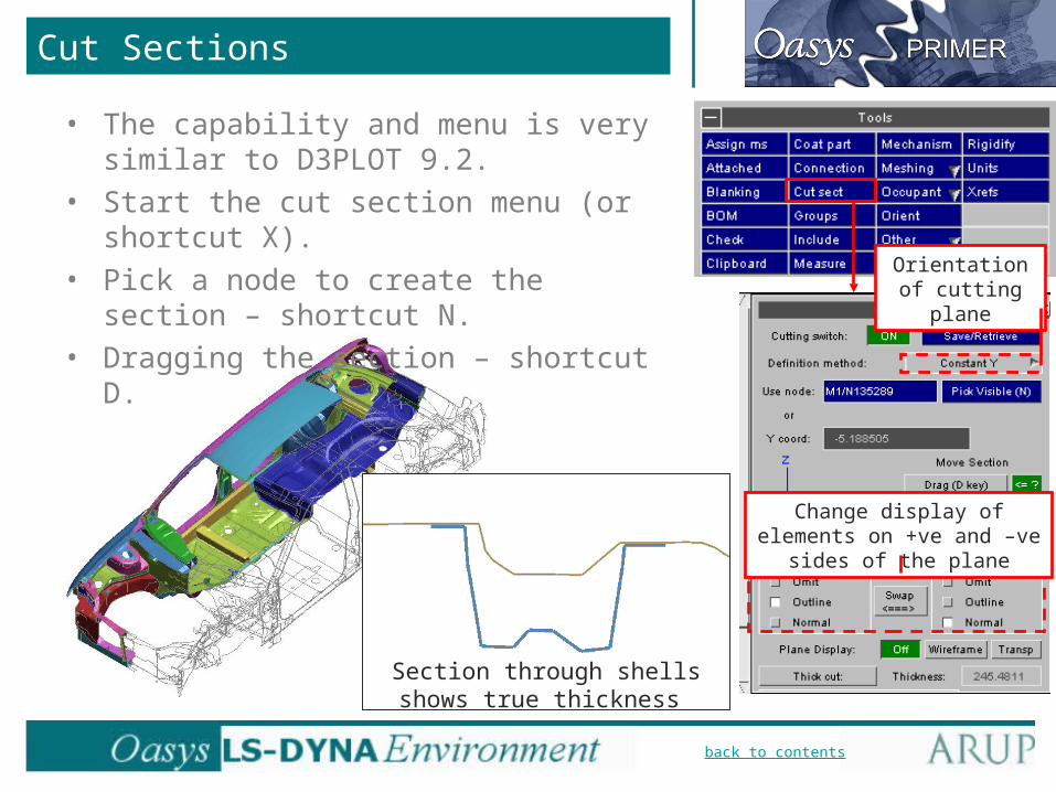
Section through shells shows true thickness
• The capability and menu is very similar to D3PLOT 9.2.
• Start the cut section menu (or shortcut X).• Pick a node to create the section –
shortcut N.• Dragging the section – shortcut D.
Change display of elements on +ve and –ve sides of the plane
Orientation of cutting plane

back to contents
INCL file location
• Edit panels now state which INCLUDE file the entity is in.
• Can change INCL file using the browse button.
• Option to Find Referenced Items.
If INCLUDE is Transformed, (T)
appears here. In this case the numbering
shown will be the transformed
numbering, not the numbering in the
keyword file.

back to contents
Text boxes
• Where the text is too long to fit in a text box, this is now indicated by white horizontal bars:
• For some text box types, the whole text can be seen by hovering over the text box with the mouse. This will be extended to all text boxes in future releases.

back to contents
INCLUDE file – Version control
• How can we tell that a model contains up-to-date INCLUDE files?
• Create “Versions” (e.g. each Version may correspond to a Design Gateway) by right-click of the Model in the Include Menu.
• Set the Version against which INCLUDE files should be checked.
back to contents
INCLUDE file – Version control
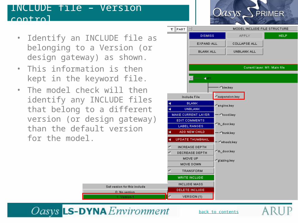
• Identify an INCLUDE file as belonging to a Version (or design gateway) as shown.
• This information is then kept in the keyword file.
• The model check will then identify any INCLUDE files that belong to a different version (or design gateway) than the default version for the model.
back to contents
Check for discontinuous rigid bodies
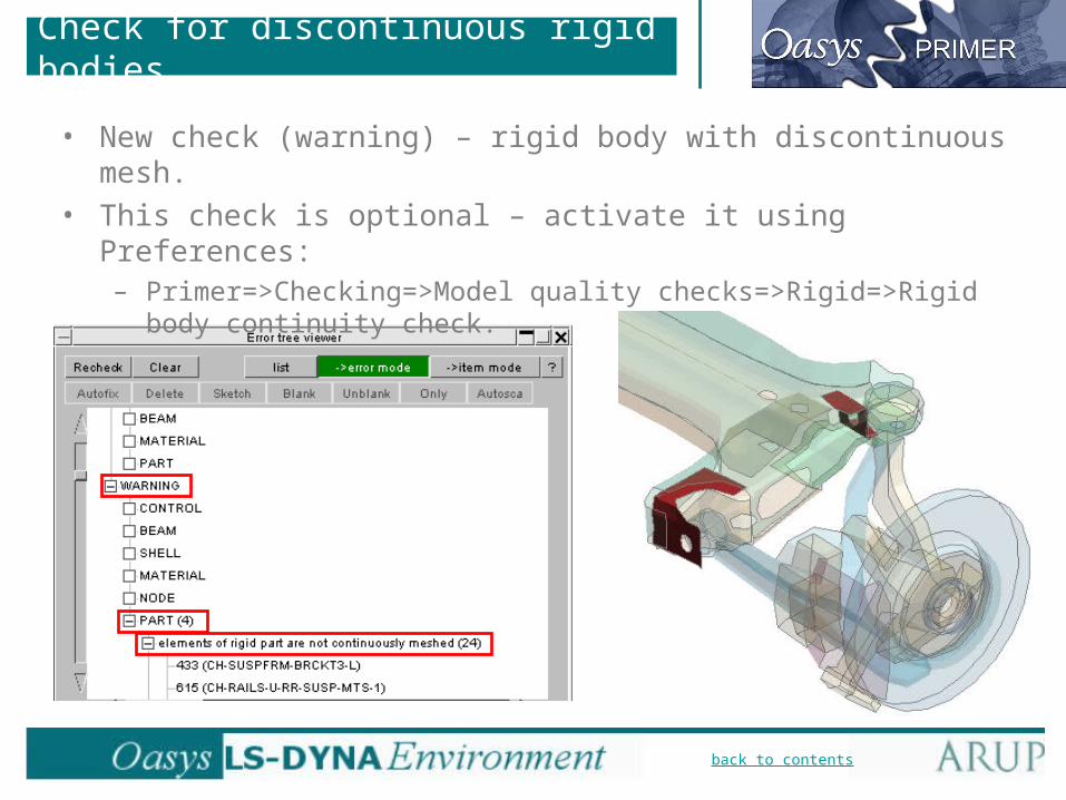
• New check (warning) – rigid body with discontinuous mesh.• This check is optional – activate it using Preferences:
– Primer=>Checking=>Model quality checks=>Rigid=>Rigid body continuity check.
back to contents
New options in Write
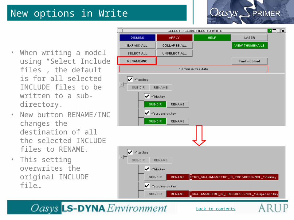
• When writing a model using “Select Include files”, the default is for all selected INCLUDE files to be written to a sub-directory.
• New button RENAME/INC changes the destination of all the selected INCLUDE files to RENAME.
• This setting overwrites the original INCLUDE file…
back to contents
New options in Write
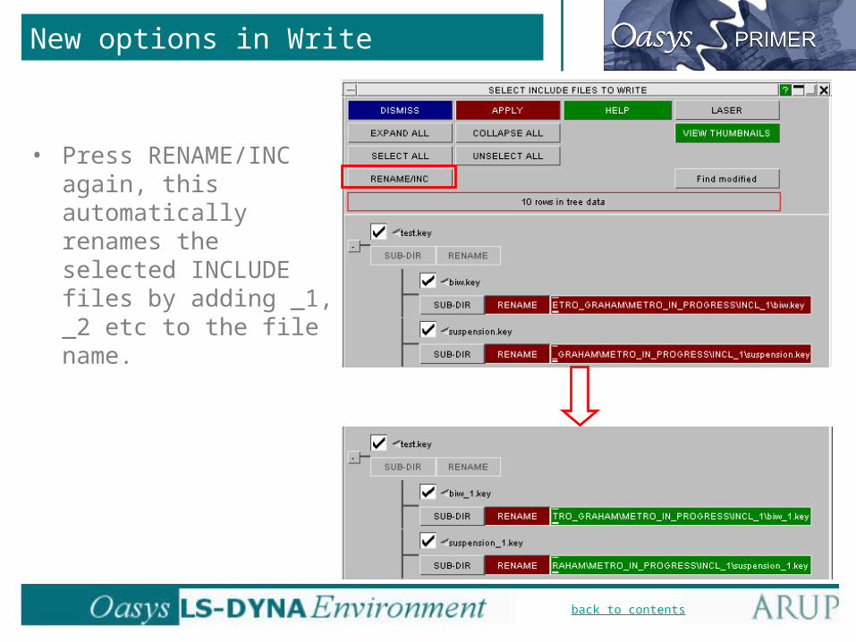
• Press RENAME/INC again, this automatically renames the selected INCLUDE files by adding _1, _2 etc to the file name.

back to contents
Miscellaneous
• Enhanced input translator for RADIOSS Block format:– Complex definitions of sets now supported.
– More material types translated.
– Engine file translated as well as Starter file.
– For further details, please contact us.
• Bill of Materials: if “calculate mass” option is set, Primer now writes the centre of gravity XYZ coordinates as well as the part mass.
• Orient Scale and Rotate: option to centre the transformation on the Part Centre of Gravity. Applies only if a single part is selected.

back to contents
Spotwelds
• Spotweld capabilities are now found under Tools=>Connection.• The same menu is used to create or modify several connection
types (spotwelds, bolts).
Primer 9.2 Primer 9.3

back to contents
• Primer 9.2 relied on *ELEMENT_BEAM_PID for many of the spotwelding functions.
• Primer 9.3 works differently – connection data is stored separately from the FE data:– Failed welds are retained in the model, can
be fixed any time.– When creating from a spotweld file, the
original XYZ coords are retained.– Easy to change the welds, e.g. beam-to-solid.– Can read and work with spotwelds that were
defined outside Primer, e.g. solid spotwelds, beam spotwelds without *ELEMENT_BEAM_PID, etc.
• Connection data created automatically on entering the spotweld menu.
• Other connection types: bolts etc.
Spotwelds
Weld file
Spotwelds
LS-DYNA model
Primer 9.2:
Weld file
Spotwelds
LS-DYNA model
Primer 9.3:
Bolts, etc
Connections

back to contents
Spotwelds
• Connection entities may be displayed separately from their FE data. They are coloured by status: green=realized, red=failed, etc.
back to contents
Solid spotwelds
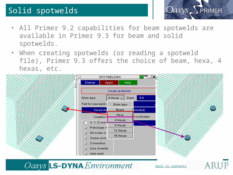
• All Primer 9.2 capabilities for beam spotwelds are available in Primer 9.3 for beam and solid spotwelds.
• When creating spotwelds (or reading a spotweld file), Primer 9.3 offers the choice of beam, hexa, 4 hexas, etc.
• *DEFINE_HEX_SPOTWELD_ASSEMBLY is created automatically in the case of multiple-hexa spotwelds.
back to contents
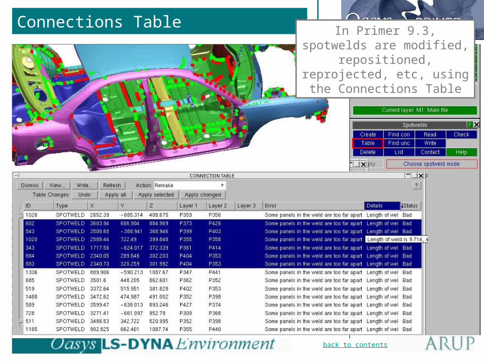
Connections TableIn Primer 9.3, spotwelds are
modified, repositioned, reprojected, etc, using the
Connections Table
back to contents
Connections Table
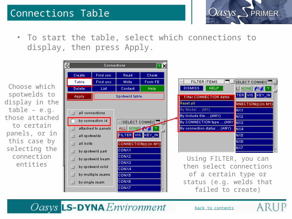
• To start the table, select which connections to display, then press Apply.
Choose which spotwelds to
display in the table – e.g. those
attached to certain panels, or in this case by selecting
the connection entities
Using FILTER, you can then select connections of a certain type or status (e.g. welds that
failed to create)

back to contents
Connections Table
Sort by clicking on the column headers, e.g. to group all the bad welds
together
back to contents
Connections Table
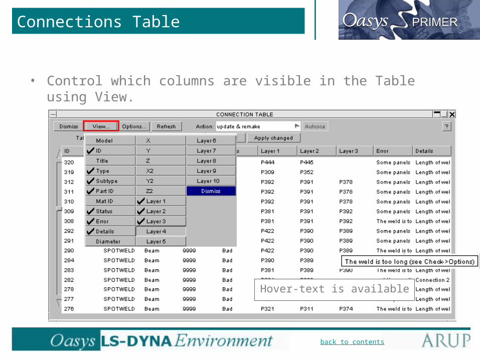
• Control which columns are visible in the Table using View.
Hover-text is available
back to contents
Connections Table
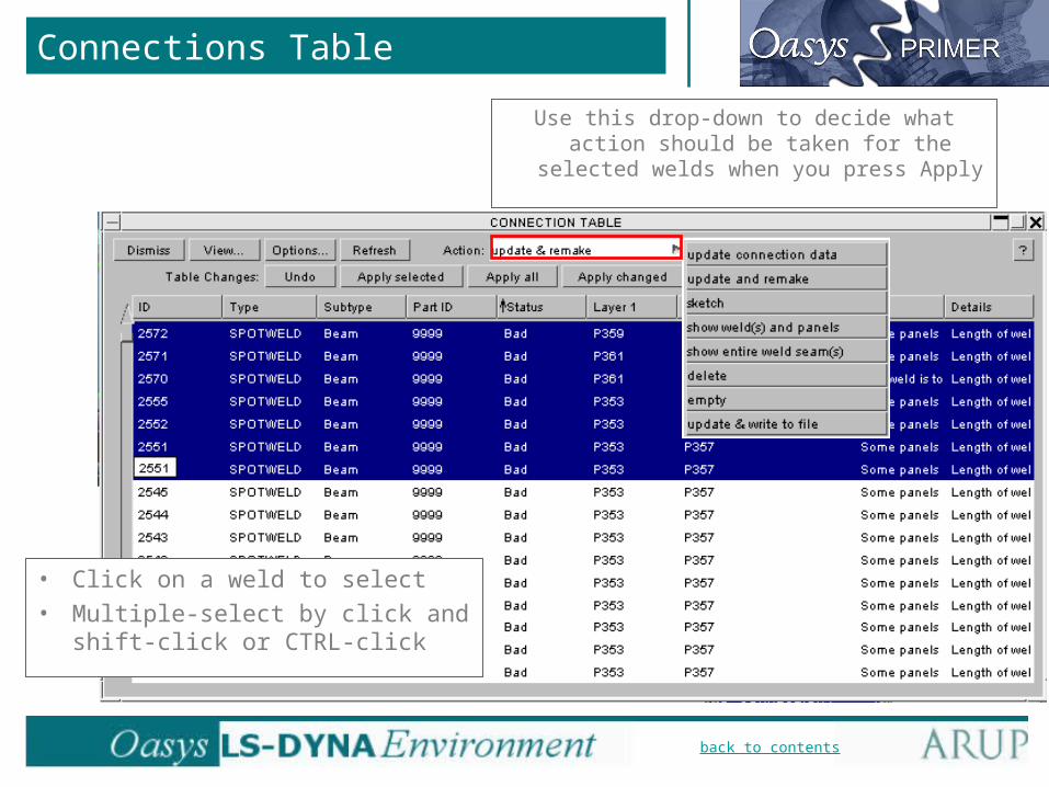
• Click on a weld to select
• Multiple-select by click and shift-click or CTRL-click
Use this drop-down to decide what action should be taken for the selected
welds when you press Apply

back to contents
Connections Table
• Changing from beam to solid spotwelds: – First, if the model does not already
contain a Part that is valid for solid spotwelds, create one.
– Select the spotwelds in the Table.– Right-click on Subtype for the selected
welds, click Solid (or 4 solids etc).– Also right-click on Part ID, select the new
Part (or if the model contains only one valid part for solid spotwelds, Primer will choose it automatically).
– Check that the Action box is set to “update & remake”.
– Press Apply Selected.– The selected welds will be re-created with
solid elements.

back to contents
Connections Table
• Repositioning a spotweld:– 1 - Select the weld (or several welds) into
the connection table.
+12
– 2 - Right-click on the coordinates, choose “Pick (from shell)”.
4
– 4 - Ensure the Action is set to “update & remake”, press “Apply selected”.
+3
– 3 - Click on the new position.

back to contents
Reading spotwelds from File
These file formats are the same as for Primer 9.2. Additional information is
needed to create the spotwelds, e.g. what type of
element should be used.
The files can be written by Primer, by CAD packages or
other programs, or csv-format from a spreadsheet.
“Primer connection file” is a new file format that contains more information. This file is created only by writing out
from Primer.

back to contents
• As the spotwelds are read from the file, connection data is created. Spotweld elements are created for error-free welds.
• Any welds with errors will have connection data with status “bad”, but no spotweld elements.
• The bad welds are automatically presented in the Connection Table.
• We recommend to add the columns “Error” and “Details” to see why the welds could not be created.
• The table can be used for fixing the welds, using the sorting, multiple-selection, right-click to change data, and “remake” facilities.
Reading spotwelds from File
back to contents
Spotwelding
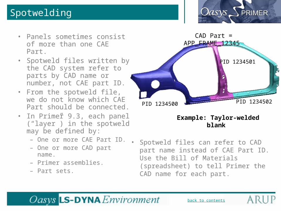
• Panels sometimes consist of more than one CAE Part.
• Spotweld files written by the CAD system refer to parts by CAD name or number, not CAE part ID.
• From the spotweld file, we do not know which CAE Part should be connected.
• In Primer 9.3, each panel (“layer”) in the spotweld may be defined by:– One or more CAE Part ID.– One or more CAD part
name.– Primer assemblies.– Part sets.
CAD Part = APP_FRAME_12345
PID 1234500
PID 1234501
PID 1234502
Example: Taylor-welded blank
• Spotweld files can refer to CAD part name instead of CAE Part ID. Use the Bill of Materials (spreadsheet) to tell Primer the CAD name for each part.

back to contents
Spotwelding
• Various methods are available in the Connections Table to define which part(s) may be connected by each spotweld:
“More” allows different Parts to be selected
For example, change definition to “Multiple Parts” and add more possible
parts to the list. The spotweld will connect to any one of the listed parts

back to contents
Spotwelding
• Various methods are available in the Connections Table to define which part(s) may be connected by each spotweld:
“Change to” changes the selection method but keeps the same Part(s)
CAD names are available only if these have been
read in via Bill of Materials
back to contents
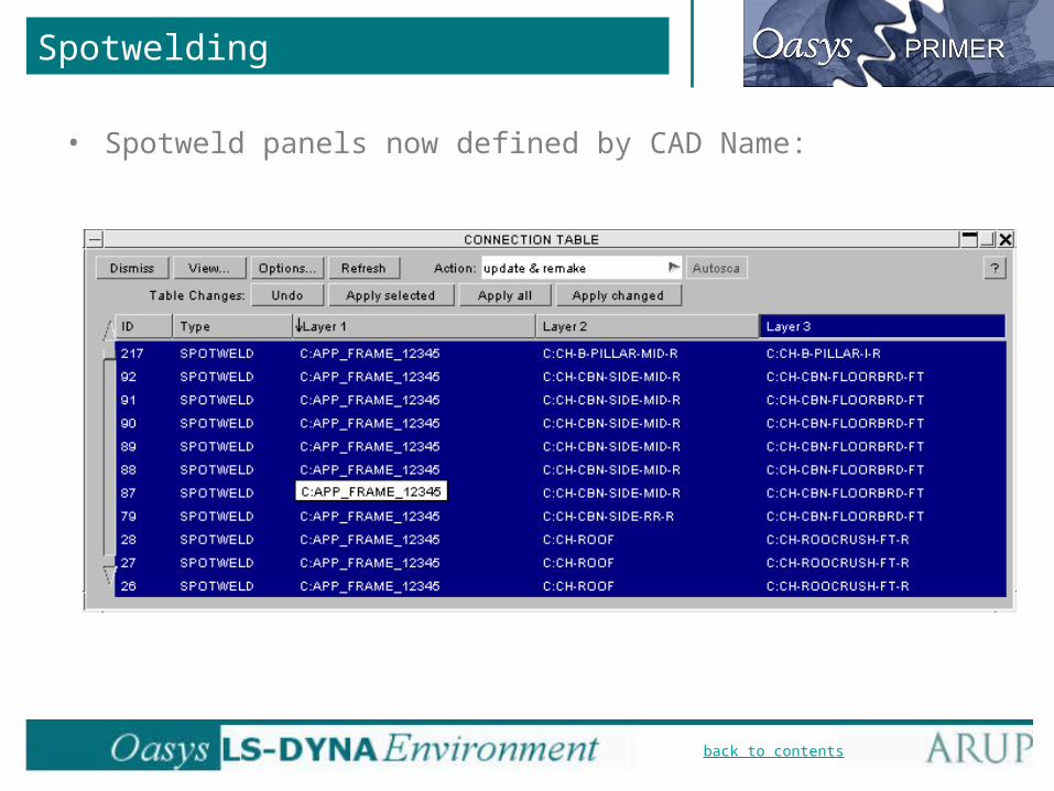
Spotwelding
• Spotweld panels now defined by CAD Name:

back to contents
Using CAD names for parts
• Read in a spreadsheet (csv format) using BOM.• Example Bill of Materials with CAD part names:
CAE Part ID CAD Part Name or number
back to contents
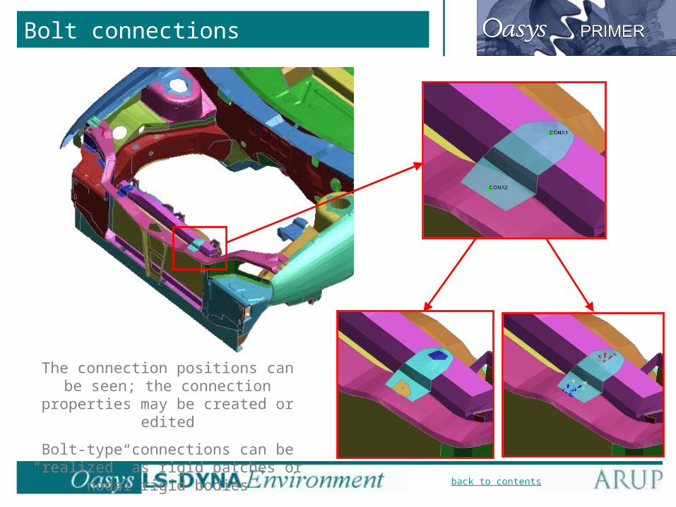
Bolt connections
The connection positions can be seen; the connection properties may be
created or edited
Bolt-type connections can be “realized” as rigid patches or nodal rigid bodies
back to contents
Bolt connections
• Manual creation of bolts through Tools=>Connections=>Create:
Bolt selection button

back to contents
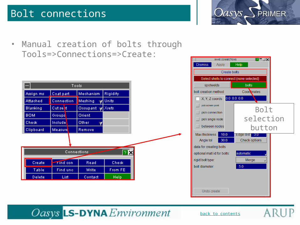
Bolt connections
• Manual creation of bolts through Tools=>Connections=>Create:
– Selection of shells/parts to connect.
– Bolt creation method:• X, Y, Z coords – type in coordinate of bolt.• Pick screen point – click on the screen to
create bolt.• Pick connection – pick an existing Primer
connection point.• Pick single node – pick an existing node
as the position of the bolt.• Between nodes – pick two existing nodes,
the bolt will be created between the nodes. Useful for creating bolts over holes.

back to contents
Bolt connections
• Manual creation of bolts through Tools=>Connections=>Create:
– Options for bolt creation.
– Data for creating bolts:• Optional matl id for bolts – If creating a
rigid body merge connection, you can specify the rigid material used here. For the default setting (automatic), Primer creates a rigid material for the bolt.
• Rigid bolt type – Two bolt types available, Merge or NRB (nodal rigid body).
• Bolt diameter – The diameter of the bolt(s) you are creating.

back to contents
Bolt connections
• Types of bolt:
– NRB’s (Nodal Rigid Bodies)• Nodal rigid bodies are
created at the connection point to the diameterspecified.
– Rigid Merges• Rigid patches are created
at the connection point to the diameter specified, and jointed by a rigid body merge.

back to contents
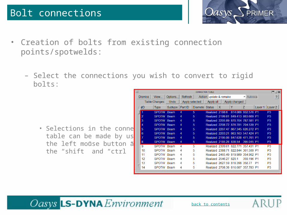
Bolt connections
• Creation of bolts from existing connection points/spotwelds:
– If you already have connection points/spotwelds in the model, these can easily be converted to rigid bolt connections using the connections table.
back to contents
Bolt connections
• Creation of bolts from existing connection points/spotwelds:
– Select the connections you wish to convert to rigid bolts:
• Selections in the connectionstable can be made by using the left mouse button and the “shift” and “ctrl” keys.

back to contents
Bolt connections
• Creation of bolts from existing connection points/spotwelds:
– The type of the connection can be changed for the selected connections:
• By right clicking over the selected connections, under the “Type” column, the “Rigid” type can be selected.

back to contents
Bolt connections
• Creation of bolts from existing connection points/spotwelds:
– Once “RIGID” is chosen for the type, the subtype can be chosen:
• By right clicking over the selected connections, under the “Subtype” column, the “Merge” or “NRB” bolt types can be selected.
back to contents
Bolt connections
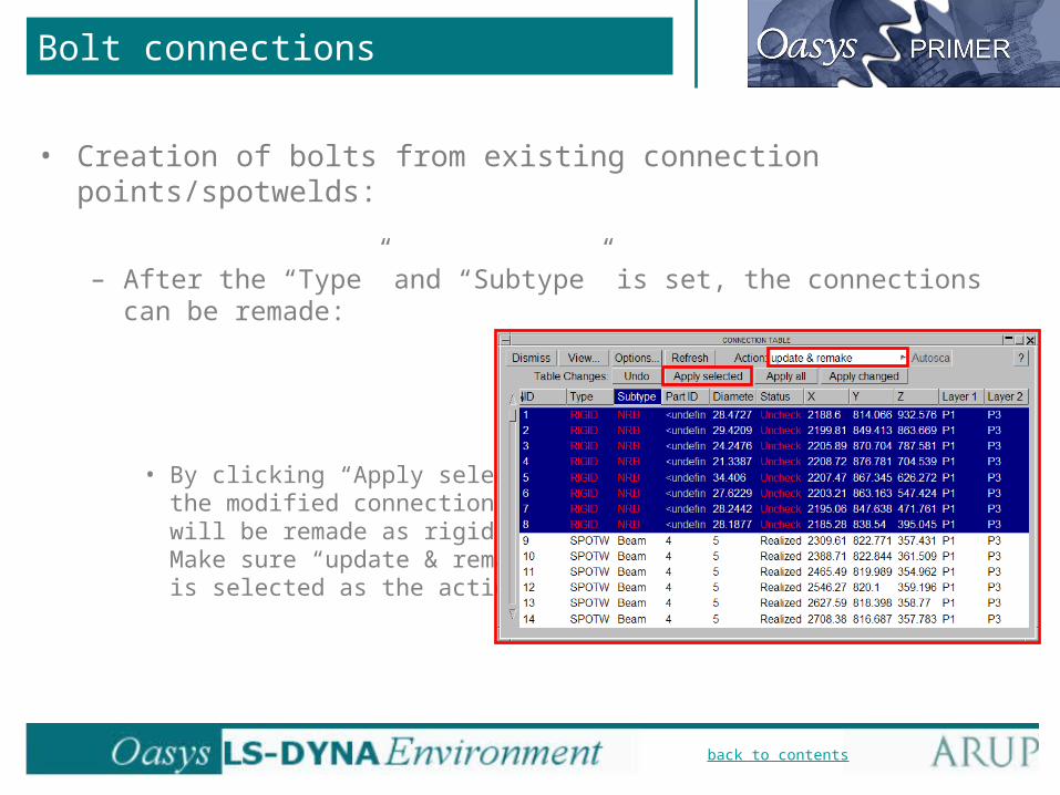
• Creation of bolts from existing connection points/spotwelds:
– After the “Type” and “Subtype” is set, the connections can be remade:
• By clicking “Apply selected” the modified connections will be remade as rigid bolts. Make sure “update & remake” is selected as the action.

back to contents
Bolt connections
• Automatic creation of connection points from constraint FE data:
– Primer can convert rigid merges and NRB’s to connection points. These connection points can then be manipulated as a standard connection definition (i.e. converted to another type (eg. spotwelds), written out to a spotweld file etc.).

back to contents
Bolt connections
• Automatic creation of connection points from constraint FE data:
– Various options are available when creating connection points from constraint FE data:
The maximum size of the constraint
selected can be set here
The type of constraint selected can be chosen here
For “Selection mode”, if “constraint” is chosen a
list of all the rigid constraints of the
selected type (NRB or merge) appears at the bottom. You select the
constraint(s) you wish to convert to a connection
definition here
back to contents
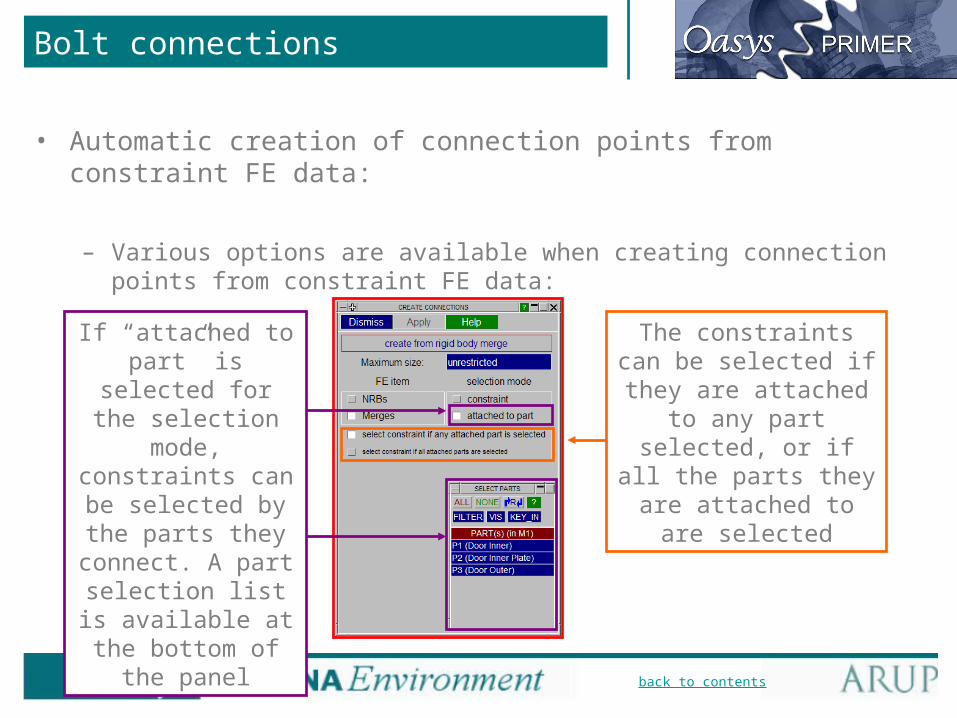
If “attached to part” is selected for the selection mode,
constraints can be selected by the parts they connect. A part
selection list is available at the
bottom of the panel
Bolt connections
• Automatic creation of connection points from constraint FE data:
– Various options are available when creating connection points from constraint FE data:
The constraints can be selected if they are attached to any part selected, or if all the
parts they are attached to are selected

back to contents
Mechanisms
Determinate: 1 DoF
Indeterminate: >1 DoF
• Primer 9.3 has a new capability to position mechanisms.
• Similar to dummy positioning, but not limited to tree-like systems.
• Mechanism can be determinate or indeterminate, and is not limited in terms of number of links or complexity.
Tree: No. DoF = No. of joints

back to contents
Mechanism definition
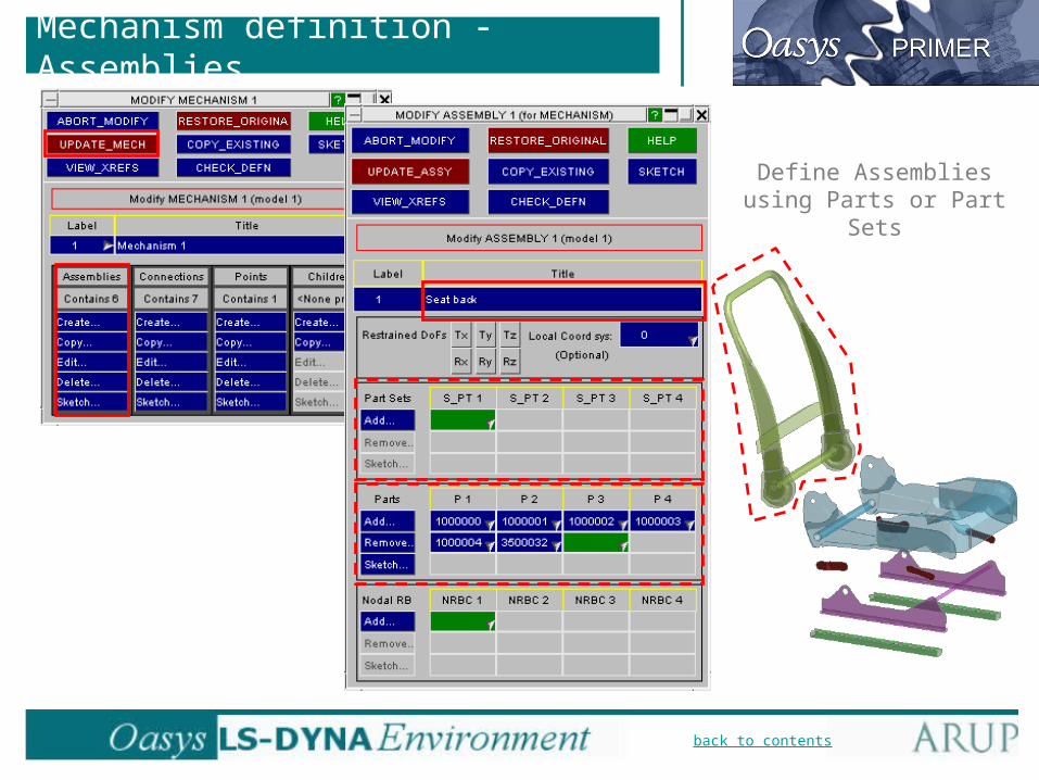
• Assemblies identified by Parts or Part Sets, e.g. back, squab, front links, etc. During positioning, each assembly will behave as if rigid.
• Connections (joints) defined at nodes. These are used purely for positioning the mechanism and are independent of any LS-DYNA joints. Connection types: pin, hinge, sliding.
• Reference Points (e.g. H-Point) – mechanism can be positioned by specifying coordinates of reference points.
Assembly
Hinge joint
Assembly
Sliding joint
back to contents
Mechanism definition
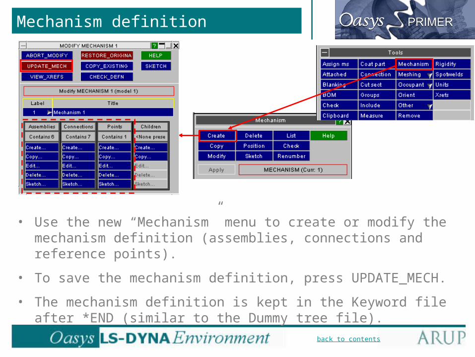
• Use the new “Mechanism” menu to create or modify the mechanism definition (assemblies, connections and reference points).
• To save the mechanism definition, press UPDATE_MECH.
• The mechanism definition is kept in the Keyword file after *END (similar to the Dummy tree file).
back to contents
Mechanism definition - Assemblies
Define Assemblies using Parts or Part Sets

back to contents
Mechanism definition - Connections
Which assemblies are joined?
Nodes to locate joint position and axis. The
nodes must be attached to one of the connected
assemblies.

back to contents
Mechanism definition - Points
To which assembly is the point attached?
Location of point using initial XYZ coordinates,
or an existing node

back to contents
Positioning the mechanism
• To start positioning the mechanism, use “Position” button.
• First, use “Drag Assemblies” menu to restrain any assemblies that should not move.
• The restraints can be altered at any time during positioning. X-translation
Y-translationZ-translation
X-rotationY-rotationZ-rotation

back to contents
• Next, use “Connection list” to lock any joints that should not be free during positioning.
• The connection status can be changed at any time during positioning.
Positioning the mechanism

back to contents
• The mechanism can be dragged at any time while in the Position menu – the assemblies will be displayed in grey during dragging. Any restraints, and the joint status (locked/free), will be respected.
Positioning the mechanism

back to contents
Positioning the mechanism
• The angular position of any assembly can be altered using the “Rotate Angles” menu.
back to contents
H-point
X1, Y1, Z1
H-point
X2, Y2, Z2
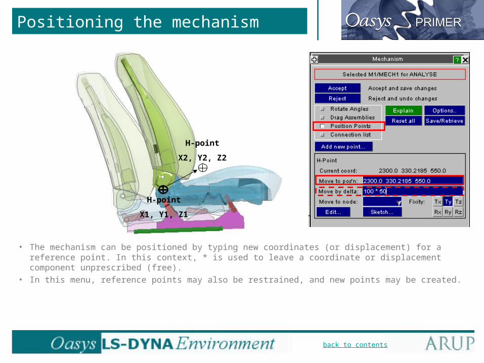
Positioning the mechanism
• The mechanism can be positioned by typing new coordinates (or displacement) for a reference point. In this context, * is used to leave a coordinate or displacement component unprescribed (free).
• In this menu, reference points may also be restrained, and new points may be created.

back to contents
Positioning the mechanism
• When you press “Accept”, the coordinates of all the newly positioned nodes will be saved in the model.
• If you press “Reject”, or dismiss the Position menu, or write out the model without pressing “Accept”, the coordinates will be reset to their previous value.
• Positions may be saved, then retrieved later. These saved positions are also written to the keyword file, so will be available next time you read in the model.
back to contents
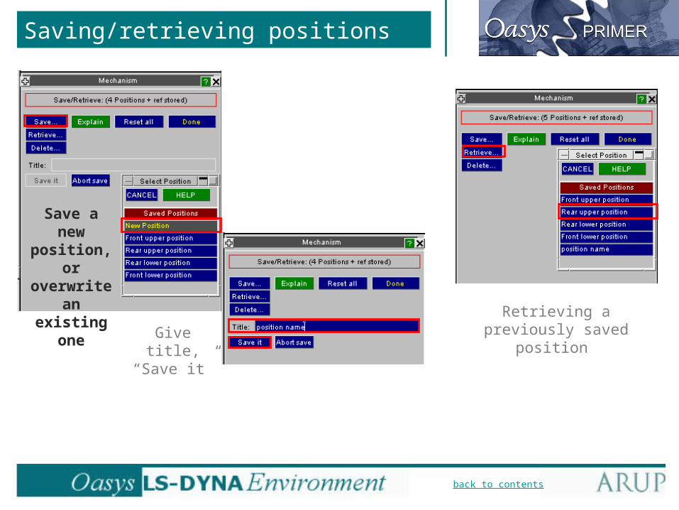
Saving/retrieving positions
Save a new position, or overwrite
an existing one
Give title, “Save it”
Retrieving a previously saved position
back to contents
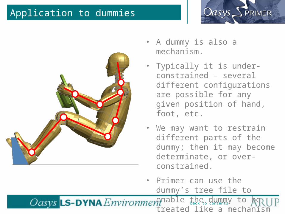
Application to dummies
• A dummy is also a mechanism.
• Typically it is under-constrained – several different configurations are possible for any given position of hand, foot, etc.
• We may want to restrain different parts of the dummy; then it may become determinate, or over-constrained.
• Primer can use the dummy’s tree file to enable the dummy to be treated like a mechanism – no additional data is required from the user.

back to contents
Dummy definition
• Assemblies identified by Parts or Part Sets, e.g. torso, head, limbs, etc. During positioning, each assembly will behave as if rigid.
• Connections (joints) automatically defined from the dummy model. No modification is allowed.
• Reference Points The H-Point is automatically available as a Reference Point; others may be created. Assembly
Hinge joint
Assembly

back to contents
Dummy Tree File Create/Modify
• After reading in a dummy key file, use Tools=>Occupant=>Dummies=>Modify to modify the dummy tree file definition. A new tree file can be created from the Create menu.
• Unlike the Modify Mechanism menu, there is no connections menu; joints are defined in the tree file as a property of Assemblies.
• To save the dummy definition, press UPDATE_DUMM.• The dummy tree file definition is kept in the Keyword file after *END.
back to contents
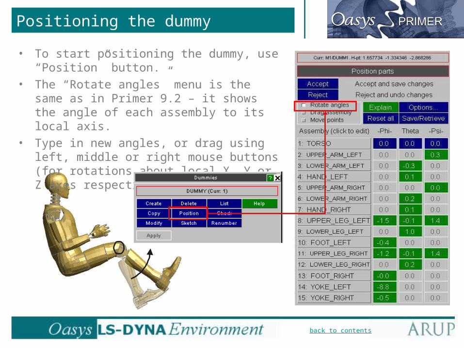
Positioning the dummy
• To start positioning the dummy, use “Position” button.
• The “Rotate angles” menu is the same as in Primer 9.2 – it shows the angle of each assembly to its local axis.
• Type in new angles, or drag using left, middle or right mouse buttons (for rotations about local X, Y or Z axes respectively).
back to contents
Positioning the dummy
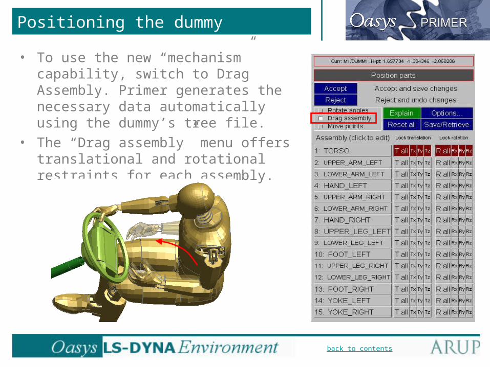
• To use the new “mechanism” capability, switch to Drag Assembly. Primer generates the necessary data automatically using the dummy’s tree file.
• The “Drag assembly” menu offers translational and rotational restraints for each assembly.
back to contents
Restraining the dummy
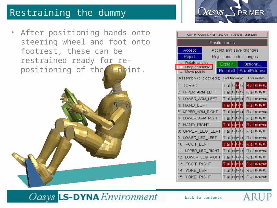
• After positioning hands onto steering wheel and foot onto footrest, these can be restrained ready for re-positioning of the H-point.

back to contents
Restraining the dummy
• Drag torso into new position (you will need to release X and Z restraints on the torso):

back to contents
Limits on drag motion
• Drag is limited by the stop-angles existing in the dummy model.
• Drag is also limited by the available degrees of freedom at each joint.
back to contents
Limits on drag motion
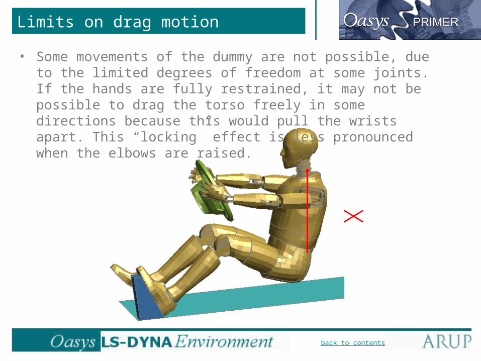
• Some movements of the dummy are not possible, due to the limited degrees of freedom at some joints. If the hands are fully restrained, it may not be possible to drag the torso freely in some directions because this would pull the wrists apart. This “locking” effect is less pronounced when the elbows are raised.

back to contents
Positioning the dummy
• The dummy has its H point already set in its model. • In this menu, reference points may be restrained, and new points may be created.• It can be useful to create reference points on the hands, knees, nose, etc so the dummy position can be
matched to measured data.
back to contents
Saving/Retrieving positions
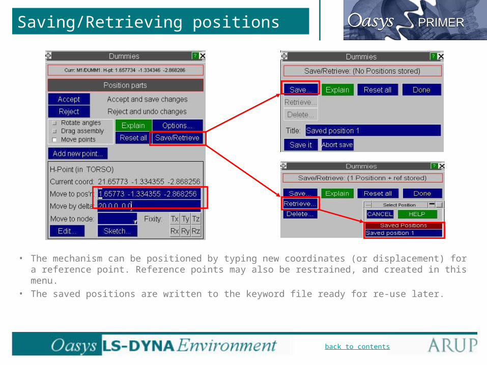
• The mechanism can be positioned by typing new coordinates (or displacement) for a reference point. Reference points may also be restrained, and created in this menu.
• The saved positions are written to the keyword file ready for re-use later.

back to contents
Saving/Retrieving positions
• Dummy Angles File – external file for transferring dummy position across models, or as a way of saving positions that can be used with successive versions of similar dummies.

back to contents
Saving dummy position
• When you “Accept” the positioning of the dummy, Primer will find that some nodal pairs at joints are no longer exactly coincident. Check the nodal separation; if small, select AUTOFIX to make the joint nodes coincident. This results in slight geometry change to the model.

back to contents
Combined mechanisms
• One mechanism may be linked to another, e.g. seat squab to dummy pelvis. Then the dummy and seat can be dragged together in a single action.
• To do this, use “children” on the mechanism menu.

back to contents
Combined mechanisms
• When defining the dummy as the child, you need to select the assemblies in the dummy to be slaved to the master mechanism.
• Select all three translational degrees of freedom to be linked. The rotations are not coupled.
c

back to contents
Combined mechanisms
• When positioning the combined mechanism, the dummy’s assemblies appear in the seat mechanism menu automatically.
• Moving the seat moves the dummy, but not vice-versa: the coupling is one-way.
• Save/Retrieve will include the combined dummy/seat position.
Seat
Dummy

back to contents
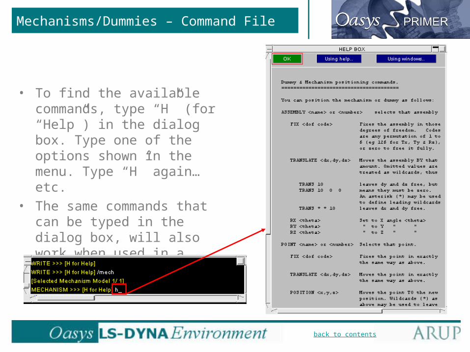
Mechanisms/Dummies – Command File
• Mechanisms and dummies may now be positioned using command-line (for example, in a command file as part of a batch process). Example:
/READ DK seat_model.key/MECHANISM ASSEMBLY 6FIX 123456DONEPOINT H-PointPOSITION 1250 400 350DONEACCEPT/WRITE DK new_model1.key/MECHPOINT H-PointPOSITION 1350 400 380DONEACCEPT/WRITE DK new_model2.key
New command MECHANISM
Can restrain, translate or rotate assemblies. If the correct restraints were already saved in the keyword file, there is no need to add commands here to restrain the assemblies.
Can restrain, translate or type new coordinates for (“Position”) Reference Points.
This command file writes two models, each with the H-point in a different position.
back to contents
• To find the available commands, type “H” (for “Help”) in the dialog box. Type one of the options shown in the menu. Type “H” again… etc.
• The same commands that can be typed in the dialog box, will also work when used in a command file.
Mechanisms/Dummies – Command File

back to contents
Seat foam compression
• Dummy has been positioned, penetrating the foam.
• “Primer” and “Dyna” methods are available to deform the foam under the dummy.
• “Primer method”:– Automatically move dummy out
of seat until there are no penetrations.
– Automatically move dummy back to its starting position, while using contact depenetration to prevent the top surface of the foam from penetrating the dummy.
– At the same time, interior nodes within the foam will be displaced to attempt to distribute the strain uniformly through the foam.

back to contents
Seat foam compression
• “Dyna method” - foam is compressed by LS-DYNA analysis:– Automatically move dummy out
of seat until there are no penetrations.
– Automatically rigidify dummy and the seat frame, create boundary condition for an LS-DYNA analysis that will move the dummy back to its starting position.
– User checks and writes out the model, runs LS-DYNA.
– Once analysed, the deformed seat geometry and initial stresses can be read back into the original model.

back to contents
Seat foam compression
• Seat squash – activated through Tools=>Occupant=>Seatsquash.
The “Squash” button is used to setup either the simple Primer seat-squash or a
LS-Dyna analysis seat-squash

back to contents
Seat foam compression
• Seat squash – Simple squash using Primer – Process:
You will get a message about saving your
model before carrying out the seat-squash
You will get a message about moving your
dummy to the H-point position
Select the top surface of the seat (eg. Null shells)
Select the bottom surface of the seat
Select the deformable foam parts of the seat
Select or create the contact between the dummy and the seat
Select the components that make up the
dummy
Select dummy movement increments
(see next slide)

back to contents
Seat foam compression
• Seat squash – Simple squash using Primer – Process:
– Increments must be chosen for the distance you want the dummy to move for each iteration during the de-penetration process.
– A value of solid element relative volume can be input to stop the seat squash should a solid element become too deformed.
– Clicking “Next” after these values are set will activate the simple seat-squash. The dummy will move away from the seat until de-penetrated, and then return to its original position, squashing the seat.
back to contents
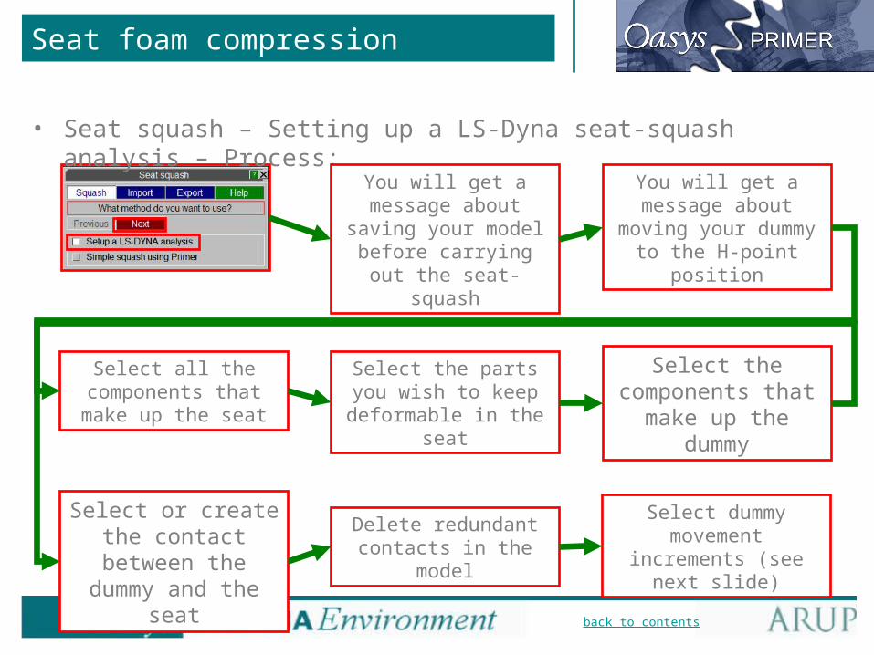
Seat foam compression
• Seat squash – Setting up a LS-Dyna seat-squash analysis – Process:
You will get a message about saving your
model before carrying out the seat-squash
You will get a message about moving your
dummy to the H-point position
Select the parts you wish to keep deformable
in the seat
Select the components that
make up the dummy
Select all the components that make
up the seat
Delete redundant contacts in the model
Select or create the contact between the dummy and the seat
Select dummy movement increments
(see next slide)
back to contents
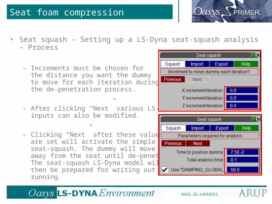
Seat foam compression
• Seat squash – Setting up a LS-Dyna seat-squash analysis – Process
– Increments must be chosen for the distance you want the dummy to move for each iteration during the de-penetration process.
– After clicking “Next” various LS-Dyna inputs can also be modified.
– Clicking “Next” after these values are set will activate the simple seat-squash. The dummy will move away from the seat until de-penetrated. The seat-squash LS-Dyna model will then be prepared for writing out and running.
back to contents
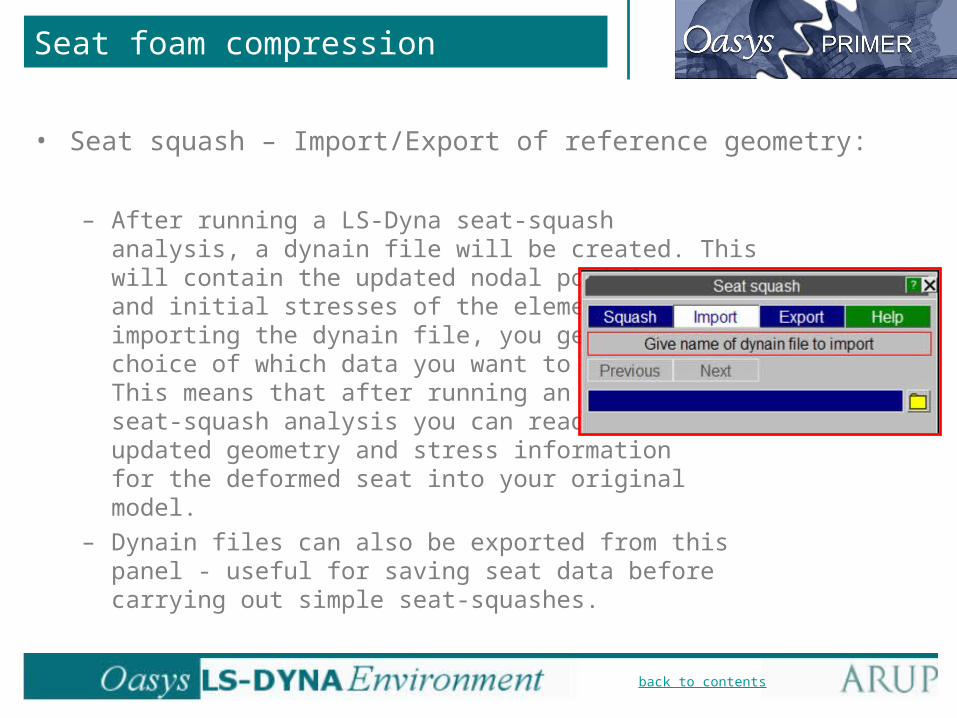
Seat foam compression
• Seat squash – Import/Export of reference geometry:
– After running a LS-Dyna seat-squash analysis, a dynain file will be created. This will contain the updated nodal positions and initial stresses of the elements. When importing the dynain file, you get the choice of which data you want to read in. This means that after running an LS-Dyna seat-squash analysis you can read the updated geometry and stress information for the deformed seat into your original model.
– Dynain files can also be exported from this panel - useful for saving seat data before carrying out simple seat-squashes.

back to contents
Instrument Panel Pendulum Impact
• New feature – setup of multiple IPP impact models for ECER21.
• Both interactive and batch mode supported.
• Easy creation/modification of target points.
• Automated positioning and de-penetration.
• True and realigned approach angle supported.
• Data saved in model or written to csv target file.

back to contents
The IP Pendulum Impactor model
• Use Arup-supplied pendulum model.• Model includes hinged base and rigid
extendable stick.• Uses VELOCITY_GENERATION for correct
initial angular velocity.• Post *END keywords store contact info, H-
point coords, impact velocities, target points.• Impactor read in as separate include file .• Written as INCLUDE or
INCLUDE_TRANSFORM for realigned approach angle case.

back to contents
IPP: Accessing the function
• IPP master menu is accessed through Occupant popup of the Primer tools menu.
back to contents
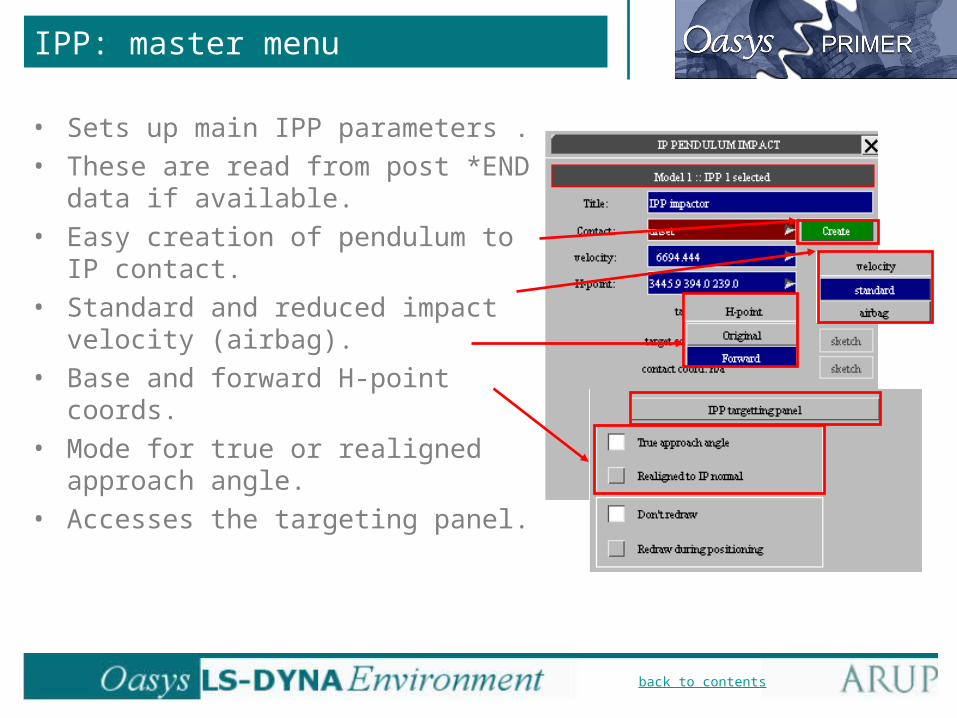
• Sets up main IPP parameters .• These are read from post *END data if
available.• Easy creation of pendulum to IP contact.• Standard and reduced impact velocity
(airbag).• Base and forward H-point coords.• Mode for true or realigned approach
angle.• Accesses the targeting panel.
IPP: master menu
back to contents
IPP: Targeting panel - functionality
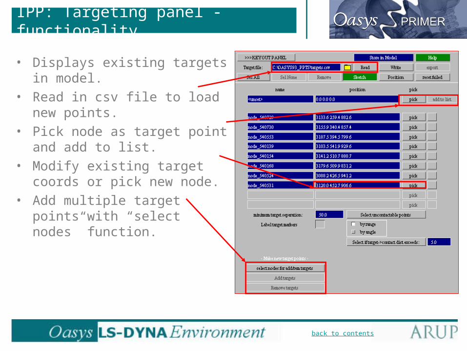
• Displays existing targets in model.• Read in csv file to load new
points.• Pick node as target point and add
to list.• Modify existing target coords or
pick new node.• Add multiple target points with
“select nodes” function.

back to contents
IPP: Targeting panel
• Initial appearance ofpanel before targeting:– Light blue background:
• Misaligned with trim normal, probably cannot be contacted by pendulum.
– Red background:• Out of range – definitely
cannot be reached by the pendulum.
– Dark blue background:• not yet positioned.
– “uncontactable points” allows removal at users discretion.
back to contents
IPP: Targeting panel - positioning
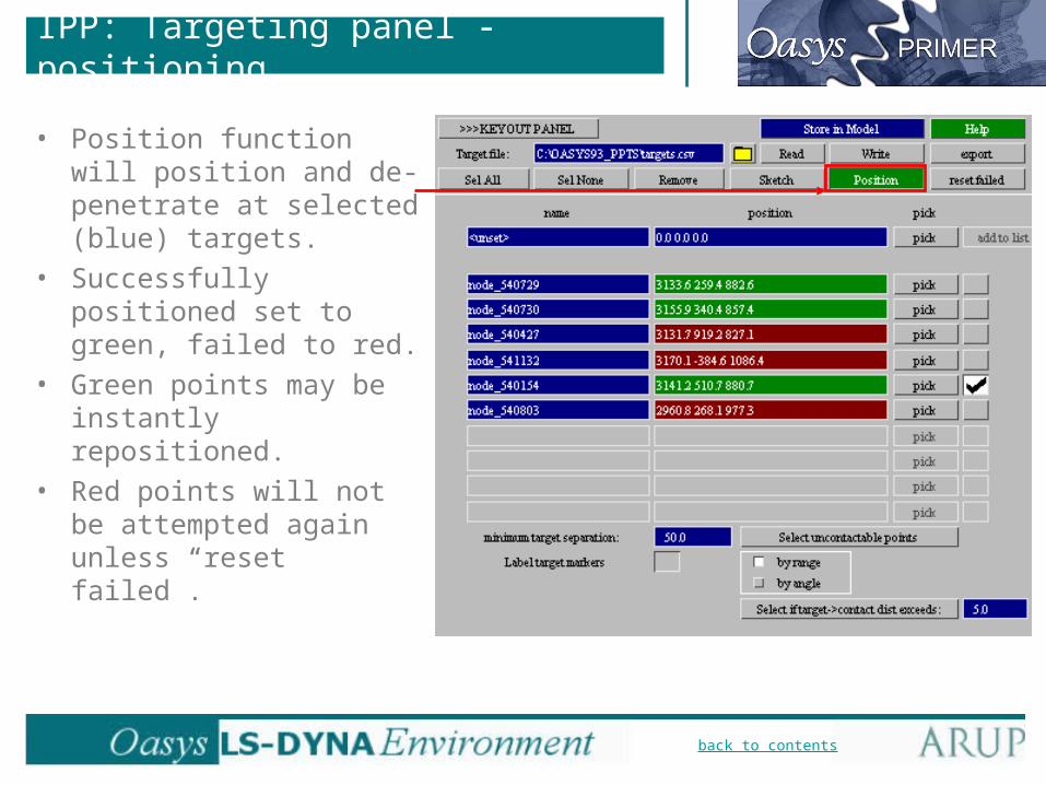
• Position function will position and de-penetrate at selected (blue) targets.
• Successfully positioned set to green, failed to red.
• Green points may be instantly repositioned.
• Red points will not be attempted again unless “reset failed”.

back to contents
IPP: Current target point information
• Master menu displays detailed positioning info for current target point.
• Target point coord. with sketch.• Contact point coord. with sketch.• Trim normal to approach gross angle.• Alpha, beta, theta angles.• Line of flight unit vector.• Velocity at centre of pendulum.
back to contents
IPP Targeting panel: Saving targets
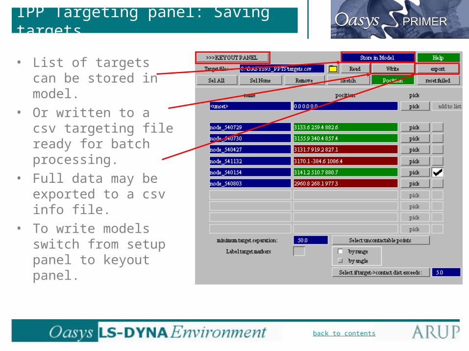
• List of targets can be stored in model.
• Or written to a csv targeting file ready for batch processing.
• Full data may be exported to a csv info file.
• To write models switch from setup panel to keyout panel.
back to contents
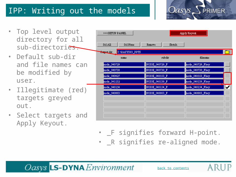
IPP: Writing out the models
• Top level output directory for all sub-directories.
• Default sub-dir and file names can be modified by user.
• Illegitimate (red) targets greyed out.
• Select targets and Apply Keyout.
• _F signifies forward H-point.• _R signifies re-aligned mode.
back to contents
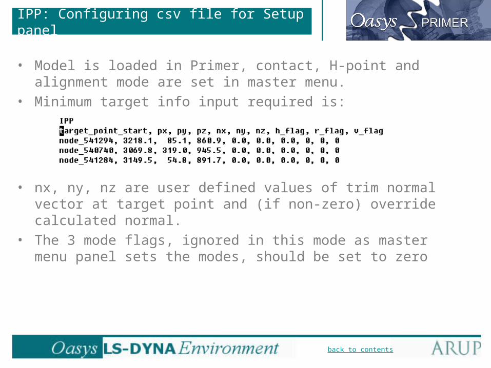
IPP: Configuring csv file for Setup panel
• Model is loaded in Primer, contact, H-point and alignment mode are set in master menu.
• Minimum target info input required is:
• nx, ny, nz are user defined values of trim normal vector at target point and (if non-zero) override calculated normal.
• The 3 mode flags, ignored in this mode as master menu panel sets the modes, should be set to zero

back to contents
IPP Batch mode
• Command line syntax for running IPP build and keyout in batch mode is: BUILD READ <target filename.csv>.
• In this case full info is required for the csv file:
• h_flag, r_flag specify the H-point and approach mode (true/aligned)
0 = nominal condition, 1 = alternative value, 2 = both loadcases• v_flag specifies the velocity
0 = nominal condition, 1 = reduced value

back to contents
Automatic Assembly (Database/Template)
• Improvements to the Database/Template system for automatic assembly of models from INCLUDE files:– INCLUDE files can be in NASTRAN format; this allows the Crash CAE
team to share data for assembly with the NVH CAE team.
– Connection files can be included in the database. The connections (spotwelds, bolts, etc) will be created during model build.
– Version control: several different versions of each component may be included in the database. The user can then select the desired version when building a model.

back to contents
Connections in Model Assembly
Unconnected parts Assembled, connected and
checked model
Primer’s Database/Template system of model assembly has been
extended to accept connection files. This method allows connections to be
created during model assembly.
Primer Connections file:- Spotwelds- Bolts- Other types…

back to contents
Gateway B Current
Body Body_a_001.k Body_b_001.k Body_try_this.k
Chassis Chassis_a_001.k Chassis_b_001.k Chassis_b_001.k
Wheels Wheels1.k Wheels1.k Wheels1.k
Engine Engine_v6_001.k Engine_v6_001.k Engine_002.k
Glazing Glazing1.k Glazing1.k Glazing2.k
In Primer 9.2, each component (INCLUDE file)
in the database has one keyword file associated
with it.
Automatic Assembly - version control
back to contents
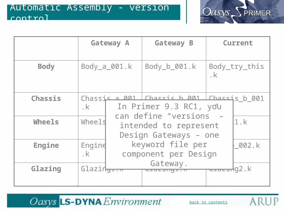
Gateway A Gateway B Current
Body Body_a_001.k Body_b_001.k Body_try_this.k
Chassis Chassis_a_001.k Chassis_b_001.k Chassis_b_001.k
Wheels Wheels1.k Wheels1.k Wheels1.k
Engine Engine_v6_001.k Engine_v6_001.k Engine_002.k
Glazing Glazing1.k Glazing1.k Glazing2.k
In Primer 9.3 RC1, you can define “versions” – intended to represent Design Gateways – one keyword
file per component per Design Gateway.
Automatic Assembly - version control

back to contents
Gateway A Gateway B Current
Body Body_a_001.k Body_b_001.k Body_try_this.k
Chassis Chassis_a_001.k Chassis_b_001.k Chassis_b_001.k
Wheels Wheels1.k Wheels1.k Wheels1.k
Engine Engine_v6_001.k Engine_v6_001.k Engine_002.k
Glazing Glazing1.k Glazing1.k Glazing2.k
One Gateway is the default; you can change the gateway selection
for the whole model or for individual components before
assembling the model.
Automatic Assembly - version control

back to contents
Automatic Assembly - version control
• This menu controls which version (Gateway) is the default, and allows new versions to be added. These will be available for all components in the database.
back to contents
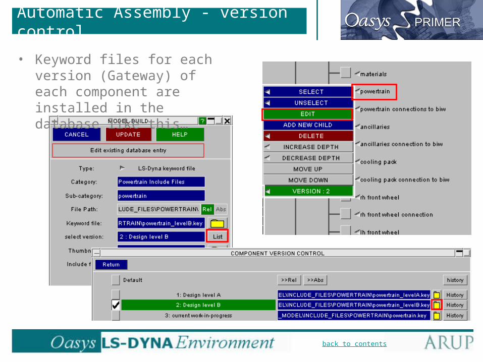
• Keyword files for each version (Gateway) of each component are installed in the database like this…
Automatic Assembly - version control

back to contents
• … then they may be selected like this…
Automatic Assembly - version control

Primer 9.3 RC1