primary standard pressure balance series cpb6000 · 2013-07-05 · calibration technology primary...
TRANSCRIPT

Calibration technology
Primary standard pressure balanceSeries CPB6000
Data sheets showing similar products:Primary standard differential pressure balance; model CPB6000DP; see data sheet CT 32.02Automatic pressure balance; model CPB8000; see data sheet CT 32.03Digital pressure balance; model CPD8000; see data sheet CT 32.04
Applications
■ High level primary standard ■ Reference instrument for factory and calibration
laboratories for the testing, adjustment and calibration of pressure measuring instruments
■ Cross-float measurement for piston-cylinder system effective area determination
■ Complete, stand-alone system, also suitable for on-site use
Special features
■ Total measurement uncertainty to 0.002 % of measured value depending on model
■ COFRAC calibration certificate included as standard ■ Available up to 1,000 bar pneumatic and 5,000 bar
hydraulic ■ 15 different piston-cylinder sizes available
DescriptionReference primary standardsPressure balances are high accuracy fundamental pressure standards that define the derived unit of pressure directly from the fundamental units of mass, length and time following the formula p = F/A.The direct measurement of the pressure with a pressure balance combined to the know-how of Desgranges & Huot guarantee the best metrological specifications on the market.
■ High quality piston-cylinder units (high floating time, long term stability)
■ Cast aluminium housing and robust sub-assemblies (minimum maintenance and overhaul services)
This type of pressure balance has been successfully tested by national institutes, calibration laboratories and all type of industries.
FunctionalityThere are five series in the CPB6000 family, which reflect a concerted long term effort to offer the user a broad range of choice in selecting a standard suited to current and future requirements.
The pressure balances of the series CPB6000 are applicable in a very wide variety of pressure calibration and measurement tasks. Appropriate configurations are available for use in primary standards laboratories and as reference instruments on the shop floor.
WIKA data sheet CT 32.01
Page 1 of 16WIKA data sheet CT 32.01 ∙ 11/2012
Primary standard pressure balance model CPB6000-HL

The instrument baseThe model CPB6000 instrument base is available in five variants:
CPB6000-PL (pneumatic - low pressure)This is a pure gas pressure standard for high level metrology application. This pressure balance uses very large area piston-cylinder systems to measure low gas pressure up to 20 bar with very high resolution down to 0.01 Pa.
CPB6000-PX (pneumatic - high pressure)This is a gas* operated pressure balance with liquid lubricated piston-cylinder systems covering the range of 0.2 ... 800 bar in standard (1,000 bar in option). The model CPB6000-PX is intended for use with any non-corrosive gas as the test medium. The use is simpler and faster than either gas lubricated pressure balances or the combination of oil operated standard and separators. Liquid lubrication eliminates the operational problems associated with gas operated pistons without compromising metrological performance.*CPB6000-PX is also available for oxygen compatibility use.
CPB6000-HL (hydraulic - range up to 1,500 bar)This is an oil operated pressure balance covering the range of 0.2 ... 1,500 bar. Model CPB6000-HL is intended for use with oil as the pressurized medium. Oil operation is the fastest and easiest way to use pressure balances. The ability to interface oil/air or oil/water using a direct visible level interface makes it possible to calibrate using another medium. The model CPB6000-HL can drive dividers and multipliers making them an excellent starting point in the configuration of an overall pressure calibration system from vacuum to 10,000 bar.
CPB6000-HX (hydraulic - range up to 5,000 bar)This is an oil operated pressure balance uses the same working principle as the CPB6000-HL with the exception that model CPB6000-HX has a 5:1 pressure intensifier enabling it to cover the range from 5 ... 5,000 bar.
CPB6000-HS (hydraulic with built-in separator)This is an oil operated pressure balance (same working principle as CPB6000-HL) covering ranges up to 1,000 bar. Those instruments are fitted with internal pressure interface oil/water or oil/gas allowing to work with gas or water with an oil pressure balance. Model CPB6000-HS has been especially designed for gas companies performing pipeline testing.Another alternative of CPB6000-HS, with built-in variable volume, is available. This pressure balance can perform hydraulic and pneumatic calibration with a single balance.
Model CPB6000-PL
Model CPB6000-PX
Models CPB6000-HL and CPB6000-HX
Model CPB6000-HS
Page 2 of 16 WIKA data sheet CT 32.01 ∙ 11/2012

Piston displacement and position monitoring
General assemblyA pressure balance designed for high accuracy, long life and optimal safety
Every detail of pressure balances series CPB6000 has been thoroughly evaluated to assure that their use is practical, safe and reliable over many years of operation. Operating components are built-in to a compact, specially designed light alloy housing that protects the operator from pressurized components and provides a rigid and stable base for piston-cylinder mounting and mass loading.Each model is presented as a complete, self-contained instrument that requires minimal bench space and is easily movable.
Components such as valves, variable volumes, pumps and reservoirs are designed, manufactured and tested to the stringent requirements of use in a high accuracy pressure standard.
Working volumes are kept to an absolute minimum. Internal tubing are ¼ inch O.D. seamless stainless steel and threaded fittings are used throughout. All tubing connects to a sump, in which liquid and solid impurities coming from the test item drop out, can be purged periodically.
The connection technology between the standard and the test item are made by leak free hand tightened quick connectors that use a pressure activated seal. All controls are easily accessible and clearly labelled. The standard’s reference level is identified by a label on the front of the housing. A platinum resistance thermometer is built-in to each instrument to monitor piston temperature.
Piston displacement and position monitoringWhen the standard is used with the mass carrying bell installed, piston position is monitored and displayed by a pointer fitted onto the end of a lever on a fulcrum. The lever’s movement multiplies the indication of the piston’s movement by a factor of 4. The operator is aware of the precise piston position and movement at all times without having to directly observe mass position relative to a scribed reference point.
As an option, electronic monitoring of piston position and displacement is available. Piston position is displayed on an analogue meter (with 5 or 25 times multiplication) on the front panel of a separate electronic module which can be placed at a location remote from the standard.
Piston rotationFor a piston-cylinder system to perform its role effectively, the piston must rotate in the cylinder. Piston rotation is maintained by means of a motor, an oval drive and pulley fitted with a drive pin. Due to the oval drive, the pulley is alternately accelerating and decelerating. The piston only receives an impulse when it has slowed down enough of the drive pin to catch it. The piston is almost always rotating completely freely at the optimum mean speed (around 30 U/min.).
The drive motor is a squirrel cage motor that can be left on all times. The automatic rotation system is set to rotate the piston in a counter clockwise direction. Piston-cylinder manufacturing techniques result in piston-cylinder systems upon which the direction of rotation has no significant effect. If rotation by hand is desired the drive pin can easily be removed.
Piston orientationIn order for the force acting on the piston to be properly calculated the piston must be vertical. For this reason, each instrument is provided with a precision bubble level and levelling feet.
Page 3 of 16WIKA data sheet CT 32.01 ∙ 11/2012
Changing the piston-cylinder system
Piston-cylinder systems inter-changeabilityNumerous inter-changeable piston-cylinder systems are available for each type of CPB6000 making possible multiple ranges with a single instrument. In all cases, changing the piston-cylinder systems requires no major disassembly. The only tool used is a special tool supplied with the standard. The maximum time required to change a piston-cylinder system is less than 1 minute.
Page 4 of 16 WIKA data sheet CT 32.01 ∙ 11/2012
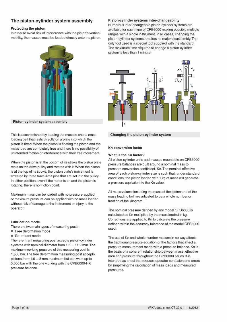
Piston-cylinder system assembly
The piston-cylinder system assemblyProtecting the pistonIn order to avoid risk of interference with the piston’s vertical mobility, the masses must be loaded directly onto the piston.
This is accomplished by loading the masses onto a mass loading bell that rests directly on a plate into which the piston is fitted. When the piston is floating the piston and the mass load are completely free and there is no possibility of unintended friction or interference with their free movement.
When the piston is at the bottom of its stroke the piston plate rests on the drive pulley and rotates with it. When the piston is at the top of its stroke, the piston plate’s movement is arrested by three travel limit pins that are set into the pulley. In either position, even if the motor is on and the piston is rotating, there is no friction point.
Maximum mass can be loaded with no pressure applied or maximum pressure can be applied with no mass loaded without risk of damage to the instrument or injury to the operator.
Lubrication modeThere are two main types of measuring posts:
■ Free deformation mode ■ Re-entrant mode
The re-entrant measuring post accepts piston-cylinder systems with nominal diameter from 1.6 ... 11.2 mm. The maximum working pressure of this measuring post is 1,500 bar. The free deformation measuring post accepts pistons from 1.6 ... 5 mm maximum but can work up to 5,000 bar with the one working with the CPB6000-HX pressure balance.
Kn conversion factor
What is the Kn factor?All piston-cylinder units and masses mountable on CPB6000 pressure balances are built around a nominal mass to pressure conversion coefficient, Kn. The nominal effective area of each piston-cylinder size is such that, under standard conditions, the piston loaded with 1 kg of mass will generate a pressure equivalent to the Kn value.
All mass values, including the mass of the piston and of the mass loading bell are adjusted to be a whole number or fraction of the kilogram.
The nominal pressure defined by any model CPB6000 is calculated as Kn multiplied by the mass loaded in kg.Corrections are applied to Kn to calculate the pressure defined within the accuracy tolerance of the model CPB6000 used.
The use of Kn and whole number masses in no way affects the traditional pressure equation or the factors that affect a pressure measurement made with a pressure balance. Kn is the basis of a coherent relationship between mass, effective area and pressure throughout the CPB6000 series. It is intended as a tool that reduces operator confusion and errors by simplifying the calculation of mass loads and measured pressures.

Pressure p
Force F
The piston cylinder "heart of the system"The piston-cylinder system is the heart of the pressure balances and the key to its performance.
The homogeneity of tungsten carbide permits ultra-precise finishing of the piston-cylinder systems. Deviation from ideal geometry is generally less than 0.1 micron (4 micro-inches). The radial clearance between piston and cylinder can be controlled very closely and varied from about 0.2 ... 1 micron (8 ... 40 micro-inch) depending on the clearance required to achieve optimum performance. The smaller diameter pistons are also available in special tool steel with minimal effect on performance since the most active element is the cylinder, which is always in tungsten carbide.
Operating typesThere are three types of CPB6000 piston-cylinder systems. The largest diameter (lowest range) piston-cylinder systems are intended for pneumatic operation and use as gas lubrication in the space between the piston-cylinder system in the Model CPB6000-PL. Piston-cylinder systems of Kn = 1 bar/kg and above exist in two versions:
■ Version 1 is intended for pneumatic operation with liquid lubrication in CPB6000-PX pressures balances.
■ Version 2 is for hydraulic operation in the CPB6000-HL and CPB6000-HX pressure balances.
The piston-cylinder systems for pneumatic operation with liquid lubrication have a groove set into the inner bore to which liquid is supplied through two radial holes.
All type of CPB6000 pistons and piston-plate assemblies are adjusted to a mass of 200 g.
A: Piston B: Piston head C: Rotation pin D: Cylinder
Fig. left: Oil operated piston-cylinder systemFig. right: Gas operated liquid lubricated piston-cylin-
der system
Diverse piston-cylinder systems
The basic principle of piston-cylinder systems p = F/A
Cross-sectional area A
Page 5 of 16WIKA data sheet CT 32.01 ∙ 11/2012
Multiple sizesThere are 15 different types of CPB6000 piston-cylinder sizes ranging from 35.3 to 1.6 mm diameter. This range of sizes includes the largest and the smallest diameters available in high accuracy pressure balances. The benefit is that it is possible to select the size from a very wide range of sizes, which is suited best for the desired pressure range and further requirements.Small diameters provide a high pressure to mass ratio which saves the user from having to manipulate excessive amounts of masses and helps to miniaturize the overall system.
Materials and machiningIn most cases, both piston and cylinder are made of tungsten carbide which is both extremely hard and wear resistant. Tungsten carbide has a Young’s modulus of about 6 x 10¹¹ N/m² and a linear thermal expansion coefficient of 4.5 x 10⁻⁶/°C. Deformation due to pressure is very low and the effect of temperature is small.

Reference mass setsReference mass sets made up of solid polished masses of the same shape and materials as CPB6000 masses can be supplied. These are convenient as in house standards for local verification or recalibration of CPB6000 mass sets.
Mass set combinations with quantities of massesMasses Mass set[kg] 40 kg 50 kg 60 kg 80 kg 100 kg5 - 8 10 14 184 - 1 1 1 12 19 2 2 2 21 1 1 1 1 10.5 1 1 1 1 10.2 2 2 2 2 20.1 1 1 1 1 1
Pressure progressionThe configuration of the mass sets allows a binary progression
■ First measuring point: piston ■ Second measuring point: piston + bell ■ Then any point up to full scale with a resolution of 100 mg
The mass setNine different mass sets are available ranging from 20 kg to 100 kg. Masses are machined out of 304 L non-magnetic stainless steel. All individual masses are whole numbers or fractions of the kilogram and are adjusted to their nominal values within the tolerance of their accuracy class. The different accuracy classes are defined as needed to achieve certain nominal accuracies on pressure. Each mass set is delivered in sturdy and attractive cabinets that are easily transportable.
The kilogramThe unit of mass used is always the kilogram because the kilogram is the SI unit and the national and international standard for mass from which all other mass units are derived. The kilogram also offers the convenience of being based on the decimal system, which facilitates mass totalling and data reduction.
Adjustment and interchangeabilityAdjusting each mass to its nominal value within the tolerance of its accuracy class allows complete mass interchangeability within one set as well as among different sets. Piston-cylinder systems are not married to specific mass sets. The masses do not need to be loaded in a prescribed sequence. Furthermore, it is not necessary to calculate the mass load in a complex way using different mass values for each mass. Whole number masses are much easier to verify and recalibrate than odd values. The advantages of adjusted masses are great and their use never significantly compromises the accuracy ultimately achieved on pressure.
Mass set configurationAll mass sets include a number of main masses of 2 or 5 kg as well as 1 kg and fractions of the kilogram down to 0.01 g. All pistons have a mass of 200 g and all loading bells a mass of 800 g. The minimum load then is 200 g and the piston loaded with the bell has a mass of 1 kg. A 5, 4, 2, 1 progression of mass values is used making it possible to load any value desired with a resolution of 0.01 g at any point in the range. Each mass is identified with the mass set serial number as well as with an individual number within the set.
Mass loadingThe 5, 2 and 1 kg masses are discs with a central hole which are loaded onto the mass carrying bell. The smaller masses are loaded onto the piston plate. The majority of the load is therefore below the centre of gravity of the piston and the entire load is well centred on the vertical axis of the piston-cylinder system.
Standard composition and custom setsThe composition of the standard CPB6000 mass sets does not include the piston assembly (200 g) and the bell (800 g). Individual masses can be added to a mass set at any time. If so desired, a unique custom mass set may be composed from standard masses.
Main masses of CPB6000 mass sets
Page 6 of 16 WIKA data sheet CT 32.01 ∙ 11/2012
CPB6000 variants and available pressure ranges
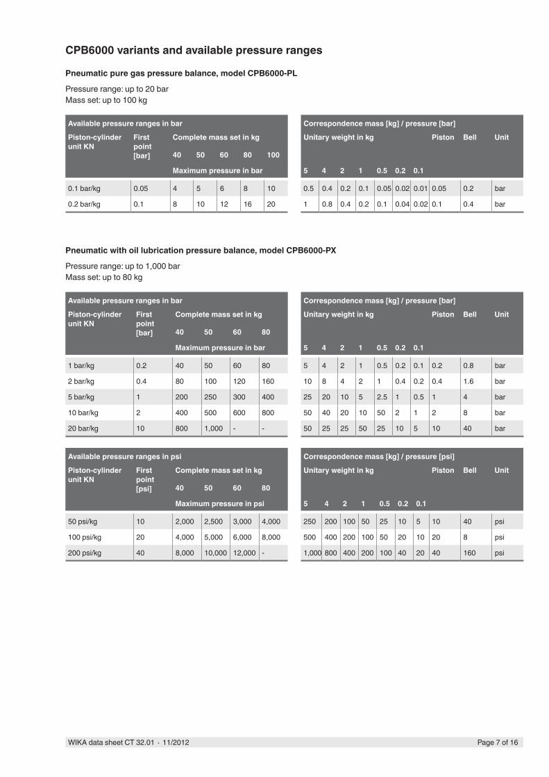
Pneumatic pure gas pressure balance, model CPB6000-PL
Pressure range: up to 20 barMass set: up to 100 kg
Available pressure ranges in bar Correspondence mass [kg] / pressure [bar]
Piston-cylinder unit KN
First point[bar]
Complete mass set in kg Unitary weight in kg Piston Bell Unit
40 50 60 80 100
Maximum pressure in bar 5 4 2 1 0.5 0.2 0.1
0.1 bar/kg 0.05 4 5 6 8 10 0.5 0.4 0.2 0.1 0.05 0.02 0.01 0.05 0.2 bar
0.2 bar/kg 0.1 8 10 12 16 20 1 0.8 0.4 0.2 0.1 0.04 0.02 0.1 0.4 bar
Pneumatic with oil lubrication pressure balance, model CPB6000-PX
Pressure range: up to 1,000 barMass set: up to 80 kg
Available pressure ranges in bar Correspondence mass [kg] / pressure [bar]
Piston-cylinder unit KN
First point[bar]
Complete mass set in kg Unitary weight in kg Piston Bell Unit
40 50 60 80
Maximum pressure in bar 5 4 2 1 0.5 0.2 0.1
1 bar/kg 0.2 40 50 60 80 5 4 2 1 0.5 0.2 0.1 0.2 0.8 bar
2 bar/kg 0.4 80 100 120 160 10 8 4 2 1 0.4 0.2 0.4 1.6 bar
5 bar/kg 1 200 250 300 400 25 20 10 5 2.5 1 0.5 1 4 bar
10 bar/kg 2 400 500 600 800 50 40 20 10 50 2 1 2 8 bar
20 bar/kg 10 800 1,000 - - 50 25 25 50 25 10 5 10 40 bar
Available pressure ranges in psi Correspondence mass [kg] / pressure [psi]
Piston-cylinder unit KN
First point[psi]
Complete mass set in kg Unitary weight in kg Piston Bell Unit
40 50 60 80
Maximum pressure in psi 5 4 2 1 0.5 0.2 0.1
50 psi/kg 10 2,000 2,500 3,000 4,000 250 200 100 50 25 10 5 10 40 psi
100 psi/kg 20 4,000 5,000 6,000 8,000 500 400 200 100 50 20 10 20 8 psi
200 psi/kg 40 8,000 10,000 12,000 - 1,000 800 400 200 100 40 20 40 160 psi
Page 7 of 16WIKA data sheet CT 32.01 ∙ 11/2012

Hydraulic pressure balance, models CPB6000-HL and CPB6000-HX
Model CPB6000-HLPressure range: up to 1,500 barMass set: up to 100 kg
Model CPB6000-HXPressure range: up to 5,000 barMass set: up to 100 kg
Available pressure ranges in bar Correspondence mass [kg] / pressure [bar]Piston-cylinder unit KN
First point[bar]
Complete mass set in kg Unitary weight in kg Piston Bell Unit
40 50 60 80 100Maximum pressure in bar 5 4 2 1 0.5 0.2 0.1
5 bar/kg 1 200 250 300 400 500 5 2.5 2.5 5 2.5 1 0.5 1 4 bar
10 bar/kg 2 400 500 600 800 1,000 10 5 5 10 5 2 1 2 8 bar
20 bar/kg 4 800 1,000 1,200 1,600 2,000 20 10 10 20 10 4 2 4 16 bar
50 bar/kg 10 2,000 2,500 3,000 4,000 5,000 50 25 25 50 25 10 5 10 40 bar
Available pressure ranges in psi Correspondence mass [kg] / pressure [psi]Piston-cylinder unit KN
First point[psi]
Complete mass set in kg Unitary weight in kg Piston Bell Unit
40 50 60 80 100Maximum pressure in psi 5 4 2 1 0.5 0.2 0.1
100 psi/kg 20 4,000 5,000 6,000 8,000 10,000 100 50 50 100 50 20 10 20 8 psi
200 psi/kg 40 8,000 10,000 12,000 16,000 20,000 200 100 100 200 100 40 20 40 160 psi
250 psi/kg 50 10,000 12,500 15,000 20,000 25,000 250 125 125 250 125 50 25 50 200 psi
300 psi/kg 60 12,000 15,000 18,000 21,000 30,000 300 150 150 300 150 60 30 60 240 psi
500 psi/kg 100 20,000 25,000 30,000 40,000 50,000 500 250 250 500 250 100 50 100 400 psi
Hydraulic pressure balance with integrated oil/water separator, model CPB6000-HS
Especially designed for pipeline testingPressure range: up to 1,000 barMass set: up to 80 kg
Available pressure ranges in bar Correspondence mass [kg] / pressure [bar]Piston-cylinder unit KN
First point[bar]
Complete mass set in kg Unitary weight in kg Piston Bell Unit
40 50 60 80Maximum pressure in bar 5 4 2 1 0.5 0.2 0.1
5 bar/kg 1 200 250 300 400 5 2.5 2.5 5 2.5 1 0.5 1 4 bar
10 bar/kg 2 400 500 600 800 10 5 5 10 5 2 1 2 8 bar
20 bar/kg 4 800 1,000 - - 20 10 10 20 10 4 2 4 16 bar
Available on demand ■ Series CPB6000 with integrated oil/gas separator (for
hydraulic and pneumatic calibrations with a single pressure balance)
■ Other piston-cylinder assemblies for hydraulic series CPB6000: 1 bar/kg and 2 bar/kg (re-entrant measuring post)
Page 8 of 16 WIKA data sheet CT 32.01 ∙ 11/2012

SpecificationsSeries CPB6000
Model CPB6000-PL CPB6000-PX CPB6000-HL CPB6000-HX CPB6000-HS
Pressure transmission medium Clean and dry air or nitrogen Hydraulic fluid: Sebacate as standard Univis J13Lubrication medium Clean and dry air
or nitrogenDrosera™ oil or Krytox™ when oxygen compat-ibility required
Hydraulic fluid: Sebacate as standard Univis J13
Material
Piston Tungsten carbide as standard; for 50 bar/kg and 500 psi/kg in special stainless steel
Cylinder Tungsten carbide
Mass set 304 L non-magnetic stainless steel
Bell 304 L non-magnetic stainless steel
Weight
Base 18 kg 27 kg 26 kg 33 kg 27 kg
100 kg mass set + piston-cylinder unit 134 kg
80 kg mass set + piston-cylinder unit 114 kg
60 kg mass set + piston-cylinder unit 89 kg
50 kg mass set + piston-cylinder unit 71 kg, with 5 kg main weights
40 kg mass set + piston-cylinder unit 52 kg, with 2 kg main weights
Dimensions in mm 410 x 420 x 460 410 x 500 x 510
PrecisionTypical precision of reading 1)
(in 1.0E-6 x P (ppm))Piston-cylinder unit Usable medium
5 0.01 MPa/kg respectively 0.1 bar/kg Pure gas
5 0.02 MPa/kg respectively 0.2 bar/kg Pure gas
10 0.1 MPa/kg respectively 1 bar/kg Gas lubricated/oil
10 20 psi/kg Gas lubricated/oil
10 / 5 0.2 MPa/kg respectively 2 bar/kg Gas lubricated/oil
10 / 5 50 psi/kg Gas lubricated/oil
5 0.5 MPa/kg respectively 5 bar/kg Gas lubricated/oil
5 100 psi/kg Gas lubricated/oil
10 / 5 1 MPa/kg respectively 10 bar/kg Gas lubricated/oil
10 / 5 200 psi/kg Gas lubricated/oil
10 250 psi/kg Oil only
10 2 MPa/kg respectively 20 bar/kg Oil only
10 300 psi/kg Oil only
15 500 psi/kg Oil only
15 5 MPa/kg respectively 50 bar/kg Oil only1) Precision is the result of √(Repeatability² + Resolution² + Linearity² + Hysteresis²) and are expressed in % of reading
Page 9 of 16WIKA data sheet CT 32.01 ∙ 11/2012

Approvals and certificates
EC conformity
Pressure equipment directive 97/23/EC (Module A)
CertificateCalibration COFRAC calibration certificate
Option: LNE/PTB calibration certificate
Transport dimensions for complete instrumentThe complete instrument, in its standard version and standard scope of delivery, consists of one package for the instrument base and up to three packages for the mass set with the following dimensions and weights, dependent upon the version.
Box with base and standard accessoriesDimensions: 650 x 625 x 730 mm
Instrument base Weight in kg
Model net gross
CPB6000-PL 24 51
CPB6000-PX 33 54
CPB6000-HL 32 53
CPB6000-HX 39 59
CPB6000-HS 33 54
Box with set of massesDimensions: 515 x 505 x 565 mm
Box with set of massesDimensions: 555 x 440 x 480 mm
Box with set of massesDimensions: 760 x 420 x 470 mm
Mass set Weight in kg Weight in kg Weight in kg Weight in kg
Version net gross net gross net gross net gross
100 kg mass set 57 69 63 75 14 26 - -
80 kg mass set 37 49 63 75 14 26 - -
60 kg mass set 42 54 33 45 14 26 - -
50 kg mass set 57 69 - - 14 26 - -
40 kg mass set - - - - - - 52 64
Scope of delivery
With pressure balance base ■ 1 Instrument base ■ 1 Spare drive belt ■ 4 Foot rest P/N 37613 ■ 1 DH1500 gland P/N 40966 ■ 1 DH1500 blind plug P/N 41009 ■ 1 Mass carrying bell (long or short depending of the model
of the pressure balance) ■ 1 Universal power supply with his power cord ■ 1 RTD output cable ■ 1 Pair of gloves ■ 1 Liter of hydraulic fluid (depending on base model) ■ 1 Seal kit ■ 1 PCA mounting key (except for model CPB6000-PL) ■ 1 DH1500 standard connector (replaced by 1 pressure
adjusting block for model CPB6000-PL)
With piston-cylinder assembly ■ Piston-cylinder assembly delivered in its storage box ■ COFRAC Calibration certificate
With mass set ■ Mass set in series of storage boxes ■ COFRAC Calibration certificate for main weights ■ Fine increment weight set
Options
■ Separators ■ Premium accuracy incl. LNE/PTB calibration certificate ■ Pressure connections and pipes
Page 10 of 16 WIKA data sheet CT 32.01 ∙ 11/2012
87
4
3
5
2
1
10
9
6
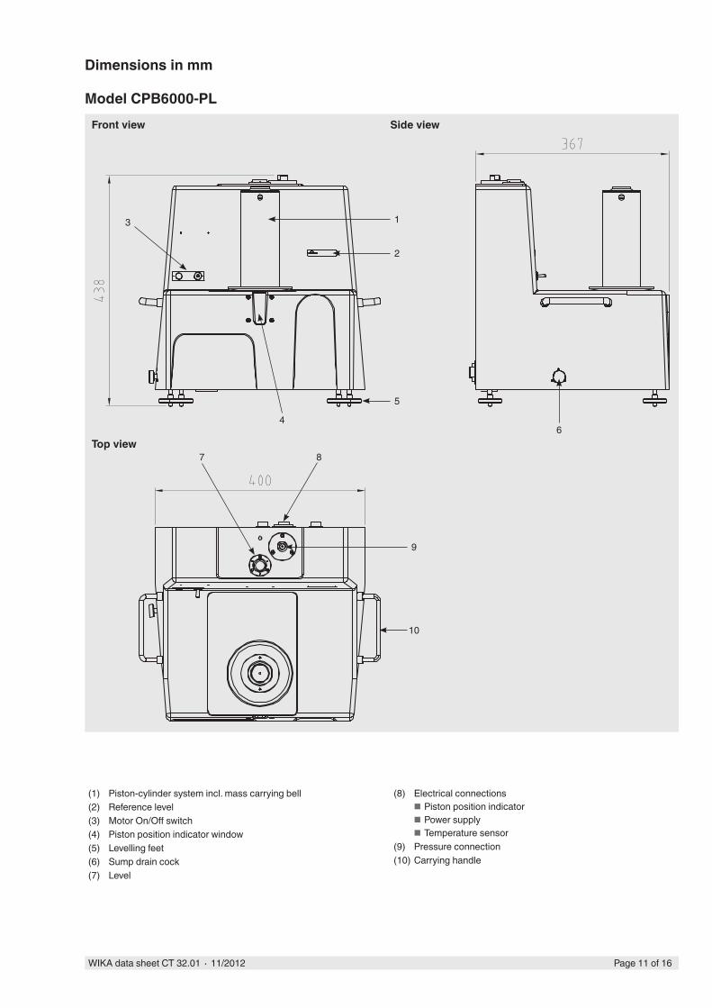
Dimensions in mm
Model CPB6000-PL
Page 11 of 16WIKA data sheet CT 32.01 ∙ 11/2012
Front view
Top view
Side view
(1) Piston-cylinder system incl. mass carrying bell(2) Reference level(3) Motor On/Off switch(4) Piston position indicator window(5) Levelling feet(6) Sump drain cock(7) Level
(8) Electrical connections ■ Piston position indicator ■ Power supply ■ Temperature sensor
(9) Pressure connection(10) Carrying handle

7
12 13
4
3
14
2
1
16
11
6
15
5
8 910
Model CPB6000-PX
Page 12 of 16 WIKA data sheet CT 32.01 ∙ 11/2012
Front view
Top view
Side view
(1) Piston-cylinder system incl. mass carrying bell(2) Reference level(3) Motor On/Off switch(4) Piston position indicator window(5) Levelling feet(6) Sump drain cock(7) Level(8) Electrical connections
■ Piston position indicator ■ Power supply ■ Temperature sensor
(9) Test item connection(10) Pressure inlet connection(11) Variable volume(12) Gas inlet valve(13) Gas outlet valve(14) Gauge indicator(15) Reservoir cap(16) Carrying handle

8
125
1
6
4
3
2
14
10
11
13
7
9
Model CPB6000-HL
Page 13 of 16WIKA data sheet CT 32.01 ∙ 11/2012
Front view
Top view
Side view
(1) Piston-cylinder system incl. mass carrying bell(2) Reference level(3) Motor On/Off switch(4) Piston position indicator window(5) Levelling feet(6) Sump drain cock(7) Level(8) Electrical connections
■ Piston position indicator ■ Power supply ■ Temperature sensor
(9) Test item connection(10) Priming pump(11) Variable volume / spindle pump(12) Reservoir isolation value(13) Oil reservoir cap(14) Carrying handle

8 910
7
13 14
4
3
2
13
2
1
18
20
12
11
6
16 15
5
Models CPB6000-HX and CPB6000-HS
Page 14 of 16 WIKA data sheet CT 32.01 ∙ 11/2012
Front view
Top view
Side view
(1) Piston-cylinder system incl. mass carrying bell(2) Reference level(3) Motor On/Off switch(4) Piston position indicator window(5) Levelling feet(6) Sump drain cock(7) Level(8) Electrical connections
■ Piston position indicator ■ Power supply ■ Temperature sensor
(9) Water connecting head (only at -HS)(10) Oil connecting head
(11) Oil variable volume(12) Priming pump (only at -HX)(13) Reservoir isolation valve (-HS)
High pressure isolation valve (-HX)(14) Oil/water interface isolation valve (-HS)
Low pressure isolation valve (-HX)(15) Oil/water interface cap (only at -HS)(16) Oil reservoir cap (15 at -HX)(17) Oil/water interface (only at -HS)(18) Water sampling isolation valve (-HS)
Reservoir isolation valve (-HX)(19) Water sampling output (only at -HS)(20) Carrying handle

Page 15 of 16WIKA data sheet CT 32.01 ∙ 11/2012
Accessories for CPB6000
Accessories and special serviceThere is a complete line of accessories and related equipment for use with CPB6000 pressure balances available. These include hardware such as seperators, gas boosters, tubing, fittings, quick-connectors, valves and manifolds. Complete multi-function calibration systems can be configured.
All accessories have been designed and manufactured by DH/WIKA or carefully selected from qualified suppliers specifically for use in high quality pressure calibration systems.WIKA welcome the opportunity to address your special requirements and to help ensure that your CPB6000 pressure balance is used to greatest advantage.
■ Would a CPB8000 automated pressure balance or a CPD8000 (digital pressure balance) be more suitable in this application?
The DH/WIKA customer service department is at your complete disposal and will do everything possible to assist you. Please do not hesitate to ask for a visit to your facility, a demonstration or a complete working evaluation.
Selection criteriaThe user can choose a variety of configuration possibilities for the series CPB6000 of pressure balances for the wide range of applications.
A complete pressure balance is configured by selecting a instrument base, a mass set and at least one piston-cylinder systems. Masses and piston-cylinder systems determine accuracy and can be up-graded, added or changed at any time. The most important decision is the selection of the base instrument or base instruments keeping in mind that mass sets and in many cases piston-cylinder systems can be used in more than one base instrument. The general information in the previous pages can direct one towards a particular series and the detail that follows should allow the selection of the most appropriate model or combination of models.
Careful consideration of the following factors will help the decision process:
■ What are the most important selection criteria: accuracy, pressure range, pressurized media, convenience of operation, ruggedness, expandability, cost, other?
■ What pressurized medium is preferred in most cases and what other media may be required?
■ What are the pressure ranges of the instruments to be calibrated and what pressure range(s) is (are) needed to cover them adequately? What pressure ranges may be required in the future?
■ In what environment will the system be operated? ■ What are the qualifications of the system operator(s)? ■ What accuracy is desired? What accuracy is needed now
and may be required in the future?

WIKA Alexander Wiegand SE & Co. KGAlexander-Wiegand-Straße 3063911 Klingenberg/GermanyTel. (+49) 9372/132-0Fax (+49) 9372/132-406E-mail [email protected]
Ordering informationModel / Instrument version / Accuracy / Piston-cylinder assembly (PCA) / Mass set / Terminal 5000 / Calibration for pressure balance / Additional order information
© 2012 WIKA Alexander Wiegand SE & Co. KG, all rights reserved.The specifications given in this document represent the state of engineering at the time of publishing.We reserve the right to make modifications to the specifications and materials.
11/2
012
GBPage 16 of 16 WIKA data sheet CT 32.01 ∙ 11/2012
Primary standard differential pressure balanceModel CPB6000DP
Measuring range = (static pressure + differential pressure):
■ Pneumatic up to 800 bar
Accuracy: 0.005 % of measured value up to 0.002 % of measured value (optional)
For specifications see data sheet CT 32.02
Further pressure balances within our calibration technology programme
Automatic pressure balance model CPB8000
Primary standard differential pressure balance model CPB6000DP
Digital pressure balance model CPD8000
Digital pressure balanceModel CPD8000
Measuring ranges: ■ Pneumatic up to 500 bar
Accuracy: 0.005 % of measured value up to 0.002 % of measured value (optional)
For specifications see data sheet CT 32.04
Automatic pressure balanceModel CPB8000
Measuring ranges: ■ Pneumatic up to 1,000 bar ■ Hydraulic up to 5,000 bar
Accuracy: 0.005 % of measured value up to 0.003 % of measured value (optional)
For specifications see data sheet CT 32.03