pretreatment of msw for co-digestion in waste water ... · pretreatment of msw for co-digestion in...
TRANSCRIPT

Pretreatment of MSW for co-digestion in waste water treatment plants
M. Meirer1,2, W. Müller1 & A. Bockreis1 1Unit of Environmental Engineering, Section of Waste and Resource Management, University of Innsbruck, Austria 2alpS – Centre for Climate Change Adaptation, Austria
Abstract
Co-digestion of organic fractions in existing digesters at waste water treatment plants is already feasible. This study shows the results of waste sorting and large scale tests to investigate the possibility of using parts of residual waste instead of common co-substrates. Most existing digesters have not originally been designed for such substrates. In particular, inert particles can settle in the digester and cause problems in the co-digestion. In a first step residual waste smaller than 40 mm was screened into eight size fractions. Each size fraction was then sorted into relevant fractions. The sorting shows that residual waste smaller than 40 mm contains about 42.5% (w/w) of organics, the residual waste smaller than 25 mm even 51% (w/w). But the sorting also shows 29% (w/w) plastics, glass, inerts and other components in the residual waste smaller than 25 mm which are not suitable for the digestion. In order to separate these physical contaminants a combination of different mechanical separation steps was tested. First a flip-flop screen was used to split the residual waste smaller than 40 mm at 5 mm and 10 mm. The fine fraction was then directed to an air jig and an organic fraction with up to 79% (w/w) volatile solids and an inert fraction with about 6% (w/w) volatile solids was achieved. The organic fraction poses a potential as co-substrate while the inert fraction could potentially be landfilled. The 5-40 mm and 10-40 mm fractions were put on a hard particle separator. The hard particle separator produced a light, intermediate and heavy fraction without increasing the organic content noticeably. However, the light fraction could meet minimum requirements for solid recovered fuel. Keywords: co-digestion, residual waste, mechanical treatment plant, waste characterisation, waste sorting, particle-size distribution, waste treatment, flip-flop screen, air jig, hard particle separator.
www.witpress.com, ISSN 1743-3541 (on-line) WIT Transactions on Ecology and The Environment, Vol 202, © 2016 WIT Press
doi:10.2495/WM160251
This paper is part of the Proceedings of the 8 International Conference th
on Waste Management and The Environment (WM 2016) www.witconferences.com

1 Introduction
The European Committee of the Regions reinforces an optimal recycling of organic waste materials through separate collection of bio-waste by 2025 in its “opinion towards a circular economy” [1]. Nevertheless organic waste can still be found in residual waste (RW) while it is already collected separately in more and more countries in Europe [2]. The amount of organic waste in RW is substantial as a selection of data from different European countries show (Table 1). In the analysis RW1 particles smaller 20 mm weren’t sorted. The respective author however mentions a significant high content of organics in the fines fraction. Furthermore, this analysis is based on dry matter in contrast to the three other analyses in Table 1. Organics contains more water than other fractions and therefore its content is higher on a wet basis. The results of Table 1 correlate with the findings of Troschinetz and Mihelcic [3], who summarized studies which show that there are about 30% (w/w) of organics in the municipal solid waste (MSW) within the USA and the EU. When the biodegradable components of the paper fraction are also considered as energy resource for digestion[4], this poses an even higher potential for biological treatment.
Table 1: Composition of residual waste (=RW) of different European Countries: RW1 [7] place/time: suburb of Mende Lozère (France) 2004/2005; RW2 [8] place/time: Treviso (Italy) 2005; RW3 [9] place/time: London (UK) 2003/2004; RW4 [10] place/time: Upper Austria 2009, Carinthia 2011.
Fraction (% (w/w)) RW1 RW2 RW3 RW4 Range Organic waste 9.1 10–16 27.2–42.7 31.4 9–43 Paper 13.5
34–50 19.8–42.4 19.7 20–50 Cardboard 9.8 Sanitary waste 8.4 5.6 6–8 Plastic 14.8 24–34 8.6–12.5 11.1 9–34 Composites 3.6 3.6 Textiles 3.2 3–8 1.3–4.1 2.9 1–8 Glass 4.2
2–14 3.8–8.6 7.0
0–14 Inert 0.3–5.1 2.8 Metal 5.4 1–9 2.9–4.5 4.4 1–5 Hazardous materials 1.1 0.1–1.1 0.7 0–1 Fines (< 20 mm RW1, <10 mm RW3) 20.5 0.4–2.8 0–21 Unclassified waste 6.6 6.4–14.3 4.3 4–14 Wood 2–4 7.9 2–8 Waste electric and electronic equipment 0.1–2.9 2.2 0–3
Incineration and mechanical biological treatment (MBT) are the most relevant options to pretreat waste prior to landfilling as requested by the EU landfill directive. Germany and Austria pioneered in the development of MBTs with the reduction of the organic fraction in RW as one main goal [5]. It is therefore interesting to note that no anaerobic MBTs can be found in Austria, while more than 60 have been installed in other countries, like Germany, Italy, Spain, France, Portugal, UK and Norway [6].
278 Waste Management and The Environment VIII
www.witpress.com, ISSN 1743-3541 (on-line) WIT Transactions on Ecology and The Environment, Vol 202, © 2016 WIT Press

In most MBT plants the RW is first shredded and then screened to separate the high caloric coarse fraction (HCF-RW) from a fines fraction. This fines fraction shows a low caloric value (LCF-RW) because the wet organic waste is concentrated in this fraction. Plants without any biological treatment step for the LCF-RW are called mechanical treatment plants (MTP). The HCF-RW is either burned in a waste to energy plant or upgraded to solid recovered fuel (SRF). For an effective anaerobic biological treatment of the LCF-RW it is important to know the exact composition of the input material with focus on the amount of organic waste like kitchen and garden waste. The fines fraction from the first screen can then be further pretreated to both increase the organics concentration and hence the biomethane potential as well as to reduce the amount of physical contaminants which can disturb the process. Mostly the separation of RW into a HCF-RW and a LCF-RW is conducted with a sieve. At the sorting line of Treviso, Italy, the amount of the organic fraction could be increased from 59.1% (w/w) up to 71.4% (w/w) with a trommel screen [8]. Bayard et al. [7] showed that after sieving at 70 mm the percentage of putrescible waste could be increased from 29.6% (w/w) up to 66.9% (w/w). In the last couple of years several authors have demonstrated the feasibility of co-digesting separately collected organic fractions of MSW in existing digesters at WWTPs [8, 11–15]. The difference of co-digestion to common anaerobic digestion is that further substrate is added to the main substrate. In this case the main substrate is sewage sludge (SS). The problem is that more and more countries forbid to use the digested sewage sludge as fertilizer on agricultural fields. In this case the valuable resource biowaste is taken out of the ecological circle. Biowaste can be used at higher value in a mono-digestion plant where the digestate remains clean and low in contaminants and can be used as fertilizer and soil improver. To still utilize existing digester capacity at waste water treatment plants (WWTP) the organics from RW could be considered as an alternative feedstock. The utilization of the organics from RW is currently investigated in a research project which includes a comprehensive characterization of the RW and different options to prepare a substrate which can be used as co-substrate in the digester of a WWTP. In this paper the results of the characterization of the LCF-RW are presented as well as mechanical separation tests to both increase the concentration of organics and reduce the amount of physical contaminants. The main objectives were to investigate the composition of the waste in different particles size fractions and the suitability of air jigs and hard particle separators to produce an organic rich fraction for co-digestion. The detailed characterization of the waste was important because very little information is available especially in regards to the fines fraction although small impurities can cause troubles in a later co-digestion at WWTPs. These digesters usually were not designed to handle inert particles. More specifically, sand, stones and glass can sink to the bottom and reduce the reactor volume [16–20]. Plastic foils can built up to a scum layer or lead to pipe blockages [19]. The knowledge about very small particles in the millimeter-scale is therefore relevant for the choice and optimization of treatment units.
Waste Management and The Environment VIII 279
www.witpress.com, ISSN 1743-3541 (on-line) WIT Transactions on Ecology and The Environment, Vol 202, © 2016 WIT Press
2 Materials and methods
2.1 Sampling
From October 2014 to December 2015 samples were taken at the MTP in Ahrental/Innsbruck, Austria. Innsbruck has about 120,000 inhabitants and recycling points for a separate collection of plastics, paper, metals, clear and stained glass. A kerbside collection exists for residual MSW and biowaste. Additionally, the MSW of the two districts Innsbruck-Land and Schwaz with about 220,000 inhabitants is also treated at the MTP Ahrental resulting in about 52,000 Mg each year. This study puts its focus on the sorting of the LCF-RW (about 22,000 Mg/a) as it shows the highest content of organics. The samples were taken after the last conveyor belt from the falling stream before entering the container to leave the plant. The prior treatment stations are the storage and mixing in the bunker as well as the crushing and screening process. These steps proved successful in homogenizing the heterogenic waste thereby decreasing the necessary amount for sorting. The minimum mass of one composite sample was calculated according to [21]:
mass (kg) = 0.06 * maximum size of particles (mm), but at least 2 kg. (1)
As the largest size fraction was defined by a sieve with 40 mm mesh size, the minimum mass of one composite sample was 2.4 kg. The composite samples were put together, mixed, coned and quartered to reduce the mass for a laboratory sample. In total, 88 samples with a total weight of 264 kg were collected over a year and mixed into 13 laboratory samples which were sorted at the laboratory. In nine of the 13 times the entire waste smaller than 40 mm was sorted as described in Table 2.
2.2 Sorting and particle size distribution
Immediately after sampling the total solids (TS) content was determined by drying at 105°C until at constant weight. The LCF-RW was screened with seven square perforated sieves as shown in Table 2 in order to determine the particle-size distribution. The relative percentages in each particle fraction were multiplied with the particle size distribution to get the absolute distribution of particular waste fractions of the LCF-RW.
2.2.1 Particle fractions between 10 mm and 40 mm The four coarse particle fractions from 10 mm to 40 mm were sorted into twelve different waste fractions. The fractions plastic and metal were divided into flat (2D) and cubic particles (3D) respectively ferrous (FM) and non-ferrous metals (NFM). The reason for this approach was that these physical properties are important for further mechanical treatment. The fraction “others” contains undefinable particles and particles which haven’t got their own waste category as, for example, compound materials.
280 Waste Management and The Environment VIII
www.witpress.com, ISSN 1743-3541 (on-line) WIT Transactions on Ecology and The Environment, Vol 202, © 2016 WIT Press

Table 2: Particle size categories and waste fractions sorted. FM = ferrous metal, NFM = non-ferrous metal, VS = volatile solids.
Particle size categories (mm) 10–16 2–4 0–2 0–0.063 16–25 4–6.3 0.063–0.125
25–31.5 6.3–10 0.125–0.25 31.5–40 0.25–0.5
0.5–1 1–2
Waste fractions sorted Organic waste Organic waste VS
no sorting, just particle-size distribution
Plastic (and rubber) 2D Plastic (and rubber)
Plastic (and rubber) 3D
Inert Inert Inert Glass Glass Glass FM
Metal Metal NFM
Paper (and cardboard) Textiles Wood
Hazardous waste Others Others Others
Ash
2.2.2 Particle fractions between 2 mm and 10 mm The smaller the particle sizes, the more difficult is the sorting. Most sorting methods have only size fractions bigger than 10 mm and call the smaller 10 mm fraction “fines” (as seen in Table 1). In this study the waste was sorted down to 2 mm albeit with a reduced number of six fractions.
2.2.3 Particle fractions smaller 2 mm To determine the particle size distribution of the waste fraction < 2 mm, the waste was first dried at 105°C and then ignited at 550°C until at constant weight. To analyse the particle-size distribution of the waste particles smaller 2 mm further five sieves were used as shown in Table 2. The advantage of calcining the LCF-RW before analyzing the particle size distribution is that small inert particles, which still were agglomerated with other particles after drying, could be recorded correctly. The disadvantage however is, that small organic but not biodegradable particles as for example plastics cannot be determined since they are burnt.
2.3 Waste treatment
Three times, samples of the LCF-RW were put into flexible intermediate bulk containers to be transported from the MTP Ahrental to the pilot plant treatment units. The first sample of 480 kg was taken in July at up to 40° Celsius ambient temperatures. Consequently, the bulk bag had to be wrapped in cellophane to prevent drying-out of the waste, which would have changed the physical properties. Further two bulk bags of 67 kg and 108 kg were taken in November. The waste was then treated (as illustrated in Figure 1).
Waste Management and The Environment VIII 281
www.witpress.com, ISSN 1743-3541 (on-line) WIT Transactions on Ecology and The Environment, Vol 202, © 2016 WIT Press

The first treatment step was a screening with a flip-flop screen. A flip-flop screen consists of an elastic screen mat which is fixed on carriers which move towards and against each other. As a result, the screen mat is repeatedly tightened and relaxed, so that the waste bounces and in consequence agglomerates are separated. The second advantage is that small waste particles do not float on the large particles due to consistent mixing which allows higher throughputs compared to rigid screens. In the trials two screen options were tested: at 5 mm and 10 mm. The fines fractions from the screening were then further treated at an air jig. The air jig consists of a perforated plate which is impinged from below with compressed air. Due to the fluidization of the air flow, light particles float on heavier particles and are passed through the downward inclination. The heavy particles however are transported upward from the translationally moving plate. The air jig aims to separate the inert components from the organic fraction.
Figure 1: Schematic chart of the flip-flop screen (above), the air jig (left) and the hard particle separator (right).
The hard particle separator has two rows of circular moved deflectors. As a result, heavy particles roll down the plates whereas light and flat particles are thrown back through the plates. The goal of the tests with the hard particle
282 Waste Management and The Environment VIII
www.witpress.com, ISSN 1743-3541 (on-line) WIT Transactions on Ecology and The Environment, Vol 202, © 2016 WIT Press

separator was to check whether or not the content of organics can be risen in one of these fractions.
3 Results and discussion
The TS content of the LCF-RW samples was 62.7 ± 4.5% (w/w) with higher moisture contents in winter (up to 72%) than in summer (down to 53%).
3.1 Sorting results of the LCF-RW <40 mm
The particle size distribution in Table 3 shows that 44.5% (w/w) of the waste was smaller 10 mm which underlines the relevance to also characterize this fraction. In the fraction smaller than 2 mm the VS-content was 42.2 % (w/w) of TS which can mainly be counted as biodegradable organics. 20.7% (w/w) of the calcined waste smaller 2 mm are heavy fractions (inert, glass and metal). In an anaerobic digestion these particles could either stay in suspension with the SS/co-substrate mixture or sink to the bottom of the reactor depending on the particle size and the intensity of mixing. Between 2 mm and 10 mm high contents of biodegradable organic waste were analyzed. The concentration of organics was higher in small particle sizes. A sharp increase was noticed at about 10 mm. In contrast the contents of light fractions as plastics, paper, textile and wood increased with larger particle sizes. 85% (w/w) of the metals were NFM as there is a FM separator but no NFM separator installed at the MTP Ahrental.
Table 3: Results of the sorting on LCF-RW. Each number is the average percentage of the sorting on a wet matter basis except 0–2 mm which got sorted after being calcined. WA = weighted average, SD = standard deviation.
Particle-size (mm) <2 2– 4
4– 6.3
6.3–10
10–16
16–25
25–31.5
31.5–40
0–40
Particle-size distribution 11.7 10.7 9.1 12.8 14.6 18.3 9.6 13.3 WA SD Organic waste 42.2 77.3 72.5 63.4 38.3 29.6 21.1 9.9 42.5 6.1 Plastic (and rubber) 2D
0.8 1.9 3.93.9 5.7 6.7 6.0 3.4 1.3
Plastic (and rubber) 3D 3.9 5.0 5.4 8.7 3.5 0.7 Inert 19.2 15.3 11.6 7.3 4.6 6.3 8.2 6.0 9.3 2.9 Glass 1.3 4.5 8.9 13.8 16.3 14.1 10.5 4.6 9.8 3.1 Ferrous metal 0.0 0.0 0.0 0.0 0.2 0.7 0.2 0.3 0.2 0.3 Non-ferrous metal 0.2 0.2 0.8 0.8 0.8 1.4 2.8 2.2 1.2 0.4 Paper (and cardboard) 15.5 20.3 25.1 33.0 12.8 7.8 Textiles 2.9 2.9 4.1 7.9 2.3 1.3 Wood 3.8 3.8 5.0 7.8 2.6 1.1 Hazardous waste 0.2 0.2 0.3 0.1 0.1 0.1 Others 21.3 1.8 4.3 10.8 11.7 10.0 10.6 13.5 10.6 3.6 Ash 15.8 1.8 6.8 Sum 100.0 100.0 100.0 100.0 100.0 100.0 100.0 100.0 100.0
Waste Management and The Environment VIII 283
www.witpress.com, ISSN 1743-3541 (on-line) WIT Transactions on Ecology and The Environment, Vol 202, © 2016 WIT Press

3.2 Absolute distribution of particular waste fractions
3.2.1 Characterisation of the LCF-RW Figure 2 shows the absolute particle size distribution of four clustered waste fractions of the LCF-RW. The values of the absolute distribution on the axis of ordinate are cumulated. The four clustered waste fractions are called “organic waste”, “heavy fraction” which could sink to the bottom of the biogas digester, “light fraction” which could lead to a scum layer and a fourth fraction called “others”. The fraction “organic waste” consists of the handsorted fraction of organics between 2 and 40 mm and the VS of the smaller 2 mm. The “heavy fraction” includes inert, glass, metal and hazardous waste as batteries. The “light fraction” contains plastics, paper, textile and wood. The fraction ash, which just occurred in the calcined size fraction smaller 2 mm, got counted to the fraction “others”. At 25 mm already 92% (w/w) of the total organic waste, at 31.5 mm already 97% (w/w) are reached. For the investigated MTP a reduction of the sieve for the LFC-RW from 40 mm to 25 mm would lead to a decrease of the annual amount of LCF-RW from 22,000 Mg to about 17,000 Mg. The amount of the organic waste in the LCF-RW would just decrease from 9,300 Mg/a to 8,600 Mg/a with a rise of the concentration of the biodegradable waste from 42.5% (w/w) to 51% (w/w) at the same time. This poses an easily implementable and cheap way for a separation of impurities. In comparison with the organic fraction the light fraction showed a growth in particle sizes which makes a sieving step between 15 mm and 20 mm very effective to separate this light fraction.
Figure 2: Combination of the results of the sorting with the particle size distribution of the LCF-RW.
- 10 20 30 40 50 60 70 80 90
100
- 4 8 12 16 20 24 28 32 36 40
particle size (mm)
organic wasteothersheavy fractionlight fraction
0 2 4 6.3 10 16 25 31.5 40
abso
lute
per
cent
ages
of
clus
terd
fr
acti
ons
(%)
284 Waste Management and The Environment VIII
www.witpress.com, ISSN 1743-3541 (on-line) WIT Transactions on Ecology and The Environment, Vol 202, © 2016 WIT Press

3.2.2 Characterisation of the LCF-RW smaller 2 mm Figure 3 presents the results of the sieving of the fraction smaller than 2 mm. The TS content of the wet fraction smaller 2 mm was 71% (w/w), the VS content 42.2% (w/w) of TS. Therefore, the dried fraction smaller 2 mm was 8.3% (w/w) and the calcined fraction 4.8% (w/w) of the whole LCF-RW. 36% (w/w) of the dried fraction smaller than 2 mm were larger than 1 mm and 65% (w/w) larger than 0.5 mm. After the calcination the glowing residues contained 24% (w/w) of particles smaller 63 µm. These results will be very important for designing waste separation units which focus on very small and heavy particles as sand and glass fragments.
Figure 3: Particle size distribution of dried and calcined LCF-RW smaller than 2 mm.
3.3 Waste treatment
The first and the second test were carried out with 5 mm and the third test with 10 mm mesh size at the flip-flop screen (Figures 4–6). In the third test there was less underflow than in the first two tests although a larger mesh size was used.
Figure 4: Results of the first treatment test (July; 5 mm mesh size).
- 1 2 3 4 5 6 7 8 9
0.063 0.125 0.250 0.500 1.000 2.000
driedcalcined
part
icle
siz
e di
stri
butio
n (%
)
particle fractions (mm)
Waste Management and The Environment VIII 285
www.witpress.com, ISSN 1743-3541 (on-line) WIT Transactions on Ecology and The Environment, Vol 202, © 2016 WIT Press
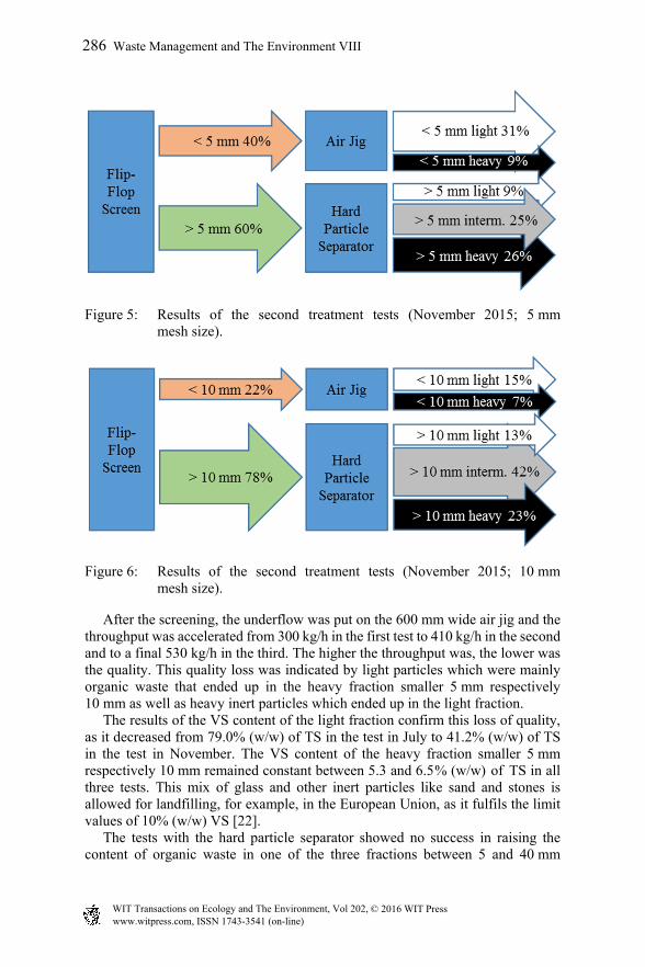
Figure 5: Results of the second treatment tests (November 2015; 5 mm mesh size).
Figure 6: Results of the second treatment tests (November 2015; 10 mm mesh size).
After the screening, the underflow was put on the 600 mm wide air jig and the throughput was accelerated from 300 kg/h in the first test to 410 kg/h in the second and to a final 530 kg/h in the third. The higher the throughput was, the lower was the quality. This quality loss was indicated by light particles which were mainly organic waste that ended up in the heavy fraction smaller 5 mm respectively 10 mm as well as heavy inert particles which ended up in the light fraction. The results of the VS content of the light fraction confirm this loss of quality, as it decreased from 79.0% (w/w) of TS in the test in July to 41.2% (w/w) of TS in the test in November. The VS content of the heavy fraction smaller 5 mm respectively 10 mm remained constant between 5.3 and 6.5 % (w/w) of TS in all three tests. This mix of glass and other inert particles like sand and stones is allowed for landfilling, for example, in the European Union, as it fulfils the limit values of 10% (w/w) VS [22]. The tests with the hard particle separator showed no success in raising the content of organic waste in one of the three fractions between 5 and 40 mm
286 Waste Management and The Environment VIII
www.witpress.com, ISSN 1743-3541 (on-line) WIT Transactions on Ecology and The Environment, Vol 202, © 2016 WIT Press
respectively 10–40 mm. However, a light and intermediate fraction rich of plastics and paper (∑=30.5-65.7% (w/w)) was separated from a heavy fraction with a high content of glass and stones (∑=34.0-49.4% (w/w)).
4 Conclusion
In this work detailed characterizations of the low caloric fraction of residual waste for the co-digestion in existing digesters of WWTPs were depicted. It could be confirmed that the content of organics rises with smaller size fractions. The LCF-RW smaller 25 mm contains already 51% (w/w) of organics compared to 42.5% (w/w) in the LCF-RW smaller 40 mm or 30% (w/w) and less in the original RW. Treatment tests with an air jig to reduce the amount of improper materials in order to produce an organic rich LCF-RW smaller than 5 mm or 10 mm showed that the volatile solids content was raised up to 79%, when a suitable throughput was used. The next steps to investigate the feasibility of co-digestion of LCF-RW in existing digesters at WWTPs are sedimentation tests with different types of stirring and reactor designs to check if problems with scum layers or sediments arise.
Acknowledgements
The competence center alpS-K1-project EneRAlp II (Organic Fraction of Municipal Solid Waste as Potential Renewable Energy- and Feedstock-Resource) gets funded by the “COMET – Competence Centers for Excellent Technologies” of BMVIT, BMWFW, federal states Tyrol and Vorarlberg and supported by the AAG Ahrental. The program COMET is carried out by the FFG.
References
[1] Committee of the regions, Opinion of the European Committee of the Regions – Towards a circular economy review of EU waste legislation. 2015.
[2] Cimpan, C., Maul, A., Jansen, M., Pretz, T., Wenzel, H., Central sorting and recovery of MSW recyclable materials: A review of technological state-of-the-art, cases, practice and implications for materials recycling. Journal of Environmental Management, 156, pp. 181–199, 2015.
[3] Troschinetz, A.M., Mihelcic, J.R., Sustainable recycling of municipal solid waste in developing countries. Waste Manag., 29, pp. 915–923 2009.
[4] Hamzawi, N., Kennedy, K.J., McLean, D.D., Technical Feasibility of Anaerobic Co-Digestion of Sewage Sludge and Municipal Solid Waste Environmental Technology. 19, pp. 993–1003, 1998.
[5] Bockreis, A., Müller, W., Best Available Techniques (BAT) for Mechanical-Biological Waste Treatment Plants. Recycling und Rohstoffe. pp. 435–444, 2014.
[6] Schneider, I., Müller, W., Bockreis, A., MBA Vergärung und Biogaserzeugung auf europäischer Ebene. 2011.
Waste Management and The Environment VIII 287
www.witpress.com, ISSN 1743-3541 (on-line) WIT Transactions on Ecology and The Environment, Vol 202, © 2016 WIT Press

[7] Bayard, R., de Araújo Morais, J., Ducom, G., Achour, F., Rouez, M., Gourdon, R., Assessment of the effectiveness of an industrial unit of mechanical–biological treatment of municipal solid waste. Journal of Hazardous Materials, 175, pp. 23–32, 2010.
[8] Bolzonella, D., Battistoni, P., Susini, C., Cecchi, F., Anaerobic codigestion of waste activated sludge and OFMSW: the experiences of Viareggio and Treviso plants (Italy). Water Science & Technology, 53 , pp. 203–211, 2006.
[9] Poll, J., Variations in the Composition of Household Collected Waste. A Report Produced for EB Nationwide, 2004.
[10] BMLFUW, Die Bestandaufnahme der Abfallwirtschaft in Österreich Statusbericht 2013. 2014.
[11] Bolzonella, D., Pavan, P., Mace, S., Cecchi, F., Dry anaerobic digestion of differently sorted organic municipal solid waste: A full-scale experience. Water Science & Technology, 53, pp. 23–32, 2006.
[12] Cavinato, C., Bolzonella, D., Pavan, P., Fatone, F., Cecchi, F., Mesophilic and thermophilic anaerobic co-digestion of waste activated sludge and source sorted biowaste in pilot- and full-scale reactors. Renewable Energy, 55, pp. 260–265, 2013.
[13] la Cour Jansen, J., Gruvberger, C., Hanner, N., Aspegren, H., Svärd, A., Digestion of sludge and organic waste in the sustainability concept for Malmö, Sweden. Water Science & Technology, 49, pp. 163–169, 2004.
[14] Ebner, C., Co-digestion of biowaste on wastewater treatment plant (WWTP), FABbiogas, Final Conference. Brüssels, Belgium, 2015.
[15] Aichinger, P., Wadhawan, T., Kuprian, M., Higgins, M., Ebner, C., Fimml, C., Murthy, S., Wett, B., Synergistic co-digestion of solid-organic-waste and municipal-sewage-sludge: 1 plus 1 equals more than 2 in terms of biogas production and solids reduction. Water Research, pp. 1–8, 2015.
[16] Carlsson, M., Lagerkvist, A., Morgan-Sagastume, F., The effects of substrate pre-treatment on anaerobic digestion systems: A review. Waste Management, 32, pp. 1634–1650, 2012.
[17] Cecchi, F., Traverso, P.G., Cescon, P., Anaerobic Digestion of Organic Fraction of Municipal Solid Wastes – Digester Performance. The Science of the Total Environment, 56, pp. 183–197, 1986.
[18] Braun, R., Wellinger, A., Potential of Co-digestion. IEA Bioenergy Task 37 – Energy from Biogas and Landfill Gas, 2002.
[19] VDI 4630 Fermentation of organic materials – Characterisation of the substrate, sampling, collection of material data, fermentation tests. 2006.
[20] Montejo, C., Ramos, P., Costa, C., Márquez, M.C., Analysis of the presence of improper materials in the composting process performed in ten MBT plants. Bioresource Technology, 101, pp. 8267–8272, 2010.
[21] ÖNORM S 2027-1 Evaluation of waste from mechanical-biological treatment – Part 1: Sampling 2012.
[22] Council Decision of 19 December 2002 establishing criteria and procedures for the acceptance of waste at landfills pursuant to Article 16 of and Annex II to Directive 1999/31/EC. 2003.
288 Waste Management and The Environment VIII
www.witpress.com, ISSN 1743-3541 (on-line) WIT Transactions on Ecology and The Environment, Vol 202, © 2016 WIT Press