pressurised thermophysical deaerator with operator manual
TRANSCRIPT

IM-P537-01 EMM Issue 1 1
Pressurised Thermophysical deaerator with operator manual for the control unit© Copyright 2021
Printed in GB
3.635.5275.275
Pressurised Thermophysical deaerator with operator manual for the control unit
Installation and Maintenance Instructions
IM-P537-01EMM Issue 1
IM-P537-01 EMM Issue 12
Pressurised Thermophysical deaerator with operator manual for the control unit
1. Safety information 5
2. General product information12
2.1 Description
2.2 Product identification 13
2.3 Identification of components
152.4 Project conditions
2.5 Operating limits
2.6 Consumption
2.7 Dimensions and weights 16
2.8 Transport and unpacking the package unit 17
3. Installation18
3.1 Installation environment
3.2 Handling, positioning and fastening 19
3.3 Process connections and draining 24
3.4 Pneumatic section connection 25
3.5 Power supply connection 26
4. Commissioning28
4.1 Pre-commissioning inspection (initial start-up)
4.2 Commissioning procedure 29
4.3 Procedure for decommissioning (shut-down)30
4.4 Environmental conditions
Contents
IM-P537-01 EMM Issue 1 3
Pressurised Thermophysical deaerator with operator manual for the control unit
5. Operation31
5.1 Operation
5.2 Control unit 33
5.3 Operator panel 36
5.4 STATUS 47
5.5 Alarms and locks 48
5.6 Graph 50
5.7 Ramp51
5.8 Settings
6. Troubleshooting 52
7. Maintenance55
7.1 General information
7.2 Replacement parts 56
7.3 Appendix A 57
7.4 Recommended inspections58
7.5 Scheduled Spirax Sarco maintenance
IM-P537-01 EMM Issue 14
Pressurised Thermophysical deaerator with operator manual for the control unit
All rights reserved.
In accordance with the legislation in force, Spirax Sarco reserves all ownership rights of this document, which may not be reproduced or transferred to third parties without prior written permission.
Spirax Sarco also reserves the right to change product specifications without prior notice.
IM-P537-01 EMM Issue 1 5
Pressurised Thermophysical deaerator with operator manual for the control unit
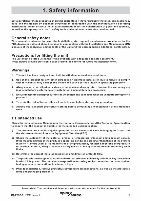
Safe operation of these products can only be guaranteed if they are properly installed, commissioned, used and maintained by qualified personnel in accordance with the manufacturer's operating instructions. General safety installation instructions for the construction of pipes and systems, as well as the appropriate use of safety tools and equipment must also be observed.
General safety notes This manual is intended to cover the installation, start-up and maintenance procedures for the PDA deaerator unit and should be used in conjunction with the Installation and Maintenance (IM) manuals of the individual components of the unit and the corresponding additional safety notes.
Precautions for lifting the unit The unit must be lifted using the lifting eyebolts with adequate and safe equipment. Note: always provide sufficient space around the system for future maintenance work.
Warnings 1. The unit has been designed and built to withstand normal use conditions.
2. Use of this product for any other purposes or incorrect installation due to failure to comply with this manual may damage the device and cause serious injury to operating personnel.
3. Always ensure that all primary steam, condensate and water return lines on the secondary are insulated before performing any installation and maintenance procedure.
4. Ensure that the residual pressure inside the system and connection pipes is vented to atmospheric pressure.
5. To avoid the risk of burns, allow all parts to cool before starting any procedure.
6. Always wear adequate protective clothing before performing any installation or maintenance work.
1.1 Intended use Check the Installation and Maintenance Instructions, the nameplate and the Technical Specification to ensure that the product is suitable for the intended use/application.
i) The products are specifically designed for use on steam and water belonging to Group 2 of the above-mentioned Pressure Equipment Directive (PED).
ii) Check the suitability of the material, pressure, temperature, minimum and maximum values. If the maximum limits of the product's operating conditions are lower than those of the system in which it is to be used, or if a malfunction of the product may result in dangerous overpressure or overtemperature, always include a safety device in the system to prevent exceeding such limits.
iii) Determine the correct installation position and direction of fluids flow.
iv) The product is not designed to withstand external stresses which may be induced by the system in which it is placed. The installer is responsible for taking such stresses into account and for taking adequate precautions to minimize them.
v) Prior to installation, remove protective covers from all connections, as well as the protective films and packaging elements.
1. Safety information

IM-P537-01 EMM Issue 16
Pressurised Thermophysical deaerator with operator manual for the control unit
1.2 PED classification The PDA thermophysical pressurised deaerators are classified as assemblies according to the European Pressure Equipment Directive (PED).The assembled unit hazard category has been determined according to the increasing hazard criteria based on Pressure (bar) per Volume (litres) or Design Pressure per ND (nominal diameter). It is understood that Spirax Sarco also used components with a higher category than the minimum required for manufacturing the pre-assembled unit.
All component parts of the assembly comply with the relevant European Directives. For further details, please refer to the specific literature.
1.3 Access Ensure safe access and, if necessary, a safe working platform (with adequate protection) before starting to work on the product. Prepare suitable lifting equipment, if necessary.
1.4 Lighting Ensure adequate lighting, particularly where detailed or complex work is required.
1.5 Hazardous liquids or gases in the pipes Take into account the contents of the pipe or the fluids that may have been previously in the pipe. Pay attention to: flammable materials, substances hazardous to health, extreme temperature.
1.6 Hazardous working environments Take into account: explosion hazard areas, lack of oxygen (e.g. tanks, wells), hazardous gases, temperature limits, hot surfaces, fire hazard (e.g. during welding), excessive noise, moving machinery.
1.7 System Consider the possible effects of the planned work on the entire system. Consider whether the intended action (e.g. closing of isolation valves, electrical isolation) may put other parts of the system or personnel at risk. The hazards may include isolation of vents or safety devices or rendering controls or alarms ineffective. Ensure that the isolation valves are gradually opened and closed to prevent sudden changes to the system.
1.8 Pressurised systems Ensure that the pressure is isolated and safely vented to atmospheric pressure. Consider double isolation (double block and vent) and locking or labelling closed valves. Do not assume that a system is depressurised even if the pressure gauge indicates zero.
1.9 Temperature Wait until the temperature returns to normal after shut off to avoid the risk of burns and consider wearing protective clothing, including safety glasses.
1.10 Tools and consumable parts Before starting installation or maintenance work, ensure that adequate tools and/or consumable parts are available. Use only original Spirax Sarco replacement parts.
IM-P537-01 EMM Issue 1 7
Pressurised Thermophysical deaerator with operator manual for the control unit
1.11 Protective clothing Consider whether you and/or others need protective clothing to protect against hazards, such as chemicals, high/low temperature, radiation, noise, falling objects and eyes and face hazards.
1.12 Work permit All work must be carried out or supervised by a qualified person. Installation and operating personnel must be trained in the correct use of the product according to the Maintenance and Installation Instructions. Any formal "work permit" system in force must be updated. Where no such system exists, it is recommended to inform a manager about the progress of the work and, where necessary, an assistant primarily responsible for safety should be appointed. Where necessary, put up a "warning" sign.
1.13 Handling Manual handling of large and/or heavy products may pose a risk of injury. Lifting, pushing, pulling, carrying or supporting a load using physical strength may cause injury, particularly back injuries. Please assess the risks by taking into account the task, the individual, the load and the working environment and use the appropriate handling method according to the circumstances of the work to be carried out. Note: where lifting straps are needed, they should be placed around the base plate to prevent damage to the unit.
1.14 Freezing Care must be taken to protect from freezing damage the products that are not self-draining in environments where they may be exposed to temperatures below freezing.
1.15 DisposalSince the product may contain PTFE and Viton, special precautions should be taken to avoid potential health hazards associated with decomposition or combustion of said materials. Unless otherwise stated in the Installation and Maintenance Instructions with regard to the materials used for the seals, this product may be recycled and it is considered that its disposal poses no ecological risk, provided that appropriate precautions are taken. However, it is possible to individually check its components to ensure that they can be safely disposed of.
PTFE - This material can only be disposed of with approved systems, never in incinerators.
- Waste from the disposal of PTFE should be stored in separate containers, never mixed with other waste materials and must be sent directly to landfill.
Viton - VITON waste can be sent to landfill when such disposal is provided for and accepted by local
and national regulations.
- VITON components can also be incinerated, but a scrubber (washing tower) must be used first to remove the hydrogen fluoride developed by the product; this procedure must be carried out in accordance with local and national regulations.
- The components are not hydrosoluble.
IM-P537-01 EMM Issue 18
Pressurised Thermophysical deaerator with operator manual for the control unit
1.16 Return of products When returning products to Spirax Sarco, customers and retailers are reminded that pursuant to the EC Health, Safety and Environment Act they must provide information on hazards and precautions to be taken because of contamination residues or mechanical damage that may present a hazard to health, safety and environment. This information must be provided in writing, including health and safety datasheets for any substance identified as hazardous or potentially hazardous.
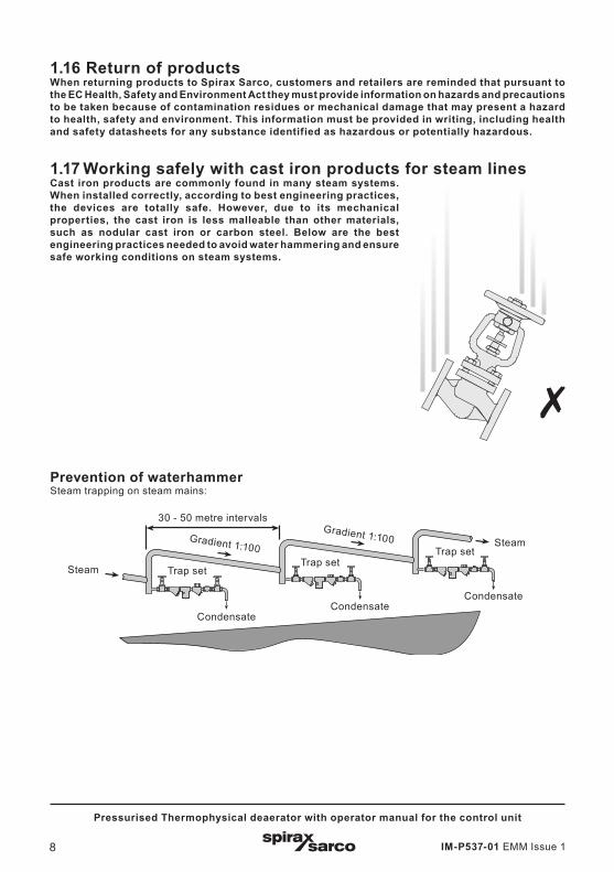
1.17 Working safely with cast iron products for steam lines Cast iron products are commonly found in many steam systems. When installed correctly, according to best engineering practices, the devices are totally safe. However, due to its mechanical properties, the cast iron is less malleable than other materials, such as nodular cast iron or carbon steel. Below are the best engineering practices needed to avoid water hammering and ensure safe working conditions on steam systems.
Prevention of waterhammer Steam trapping on steam mains:
30 - 50 metre intervalsGradient 1:100Gradient 1:100
Trap setTrap set
Trap set
CondensateCondensate
Condensate
Steam
Steam
IM-P537-01 EMM Issue 1 9
Pressurised Thermophysical deaerator with operator manual for the control unit
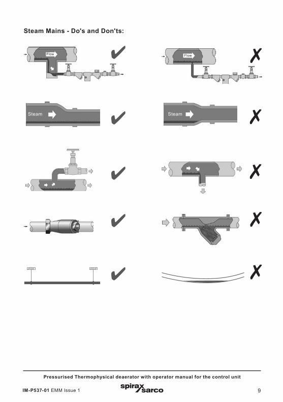
Steam Mains - Do's and Don'ts:
Steam Steam
Flow Flow
IM-P537-01 EMM Issue 110
Pressurised Thermophysical deaerator with operator manual for the control unit
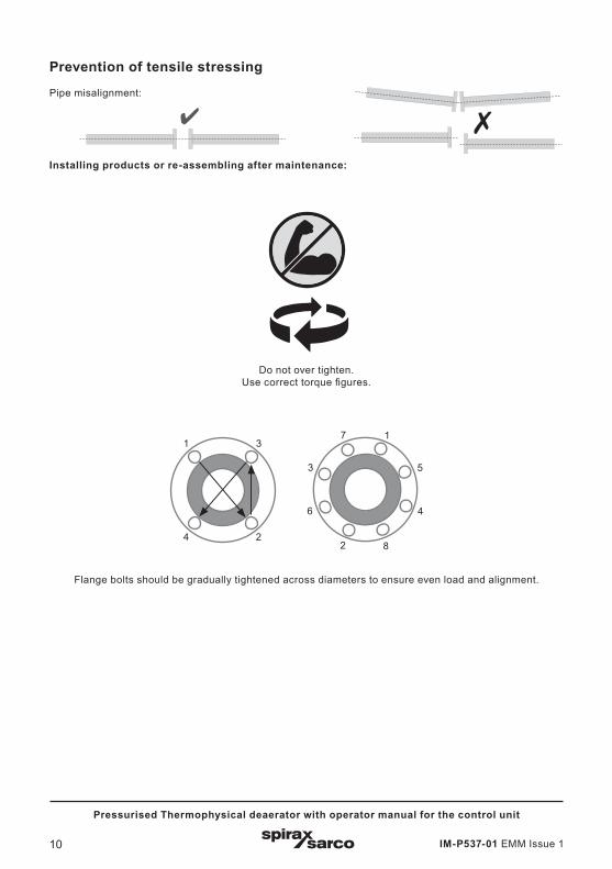
Prevention of tensile stressing Pipe misalignment:
Installing products or re-assembling after maintenance:
Do not over tighten.Use correct torque figures.
11
4 2
3
82
6
3
7
Flange bolts should be gradually tightened across diameters to ensure even load and alignment.
5
4
IM-P537-01 EMM Issue 1 11
Pressurised Thermophysical deaerator with operator manual for the control unit
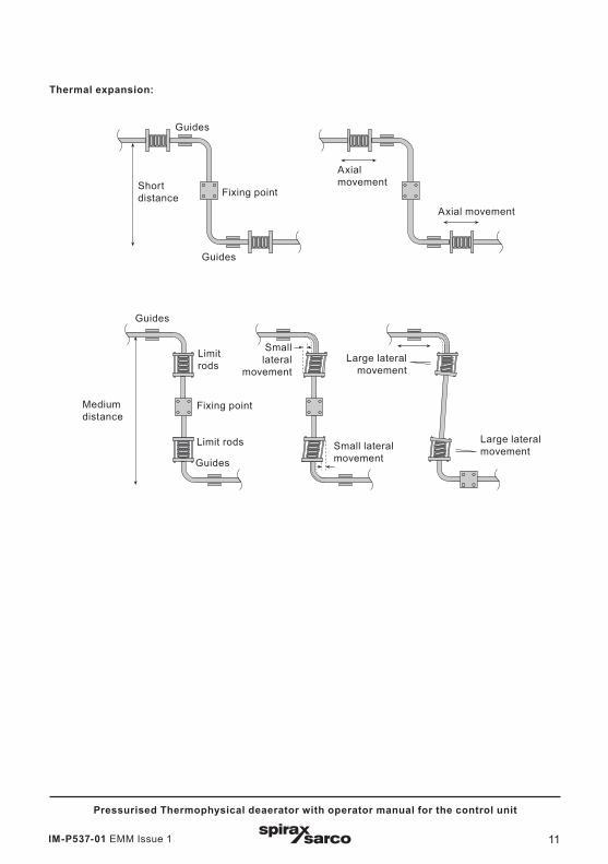
Thermal expansion:
Guides
Guides
Limit rods
Limit rods
Fixing pointMedium distance
Small lateral
movement
Small lateral movement
Large lateral movement
Large lateral movement
Short distance Fixing point
Axial movement
Axial movement
Guides
Guides

IM-P537-01 EMM Issue 112
Pressurised Thermophysical deaerator with operator manual for the control unit
2.1 DescriptionThe thermophysical deaerator is used in most systems requiring removal of gases that can damage boilers and pipes.
The theories involved in the removal of gases dissolved in liquids are based on tables and chemical principles, such as Dalton's and Henry's Law. All gases become soluble when the water steam pressure and the dissolved gas pressure exceed the pressure imposed on the system. Water cannot contain dissolved gases at 100 °C saturation temperature at atmospheric pressure or 120.4 °C at 1 bar (assuming sea level conditions).
2. General product information
Fig. 1
The PDA unit consists of the following main parts:
1. Primary steam assembly
2. Thermophysical deaerator and instrumentation/accessories/protection/safety devices
3. Make-up water assembly
4. Electrical control panel
For detailed parts list and specifications, refer to the P&ID and documentation provided with the unit.
Notes:
1. For further information regarding each particular element of the system, refer to the specific technical documentation (TI) for each product.
2. Further technical information regarding PDA thermophysical pressurised deaeration solutions can be found in the TI-5B.175-E.
IM-P537-01 EMM Issue 1 13
Pressurised Thermophysical deaerator with operator manual for the control unit
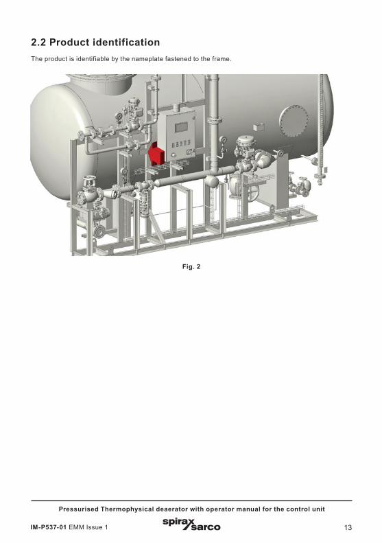
2.2 Product identificationThe product is identifiable by the nameplate fastened to the frame.
Fig. 2
IM-P537-01 EMM Issue 114
Pressurised Thermophysical deaerator with operator manual for the control unit
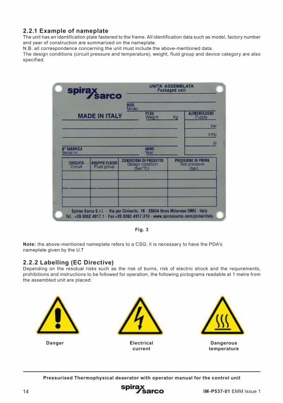
2.2.1 Example of nameplateThe unit has an identification plate fastened to the frame. All identification data such as model, factory number and year of construction are summarized on the nameplate. N.B. all correspondence concerning the unit must include the above-mentioned data. The design conditions (circuit pressure and temperature), weight, fluid group and device category are also specified.
Fig. 3
Note: the above-mentioned nameplate refers to a CSG; it is necessary to have the PDA'snameplate given by the U.T
2.2.2 Labelling (EC Directive)Depending on the residual risks such as the risk of burns, risk of electric shock and the requirements, prohibitions and instructions to be followed for operation, the following pictograms readable at 1 metre from the assembled unit are placed:
Danger Electrical current
Dangerous temperature
IM-P537-01 EMM Issue 1 15
Pressurised Thermophysical deaerator with operator manual for the control unit
2.3 Identification of componentsFor the identification of the components installed on the unit, refer to the P&ID and the technical documentation of the project.
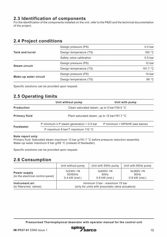
2.4 Project conditions
Tank and turret
Design pressure (PS) 0.5 bar
Design temperature (TS) 160 °C
Safety valve calibration 0.5 bar
Steam circuitDesign pressure (PS) 12 bar
Design temperature (TS) 191.7 °C
Make-up water circuitDesign pressure (PS) 10 bar
Design temperature (TS) 99 °C
Specific solutions can be provided upon request.
2.5 Operating limits Unit without pump Unit with pump
Production Clean saturated steam, up to 5 bar/159.0 °C
Primary fluid Plant saturated steam, up to 12 bar/191.7 °C
Feedwater P minimum ≥ P steam generation + 0.5 bar P minimum = NPSHR (see below)
P maximum 8 bar/T maximum 110 °C
Note report only:Primary fluid: Saturated steam maximum 12 bar g/191.7 °C before pressure reduction assemblyMake-up water maximum 6 bar g/99 °C (instead of feedwater)
Specific solutions can be provided upon request.
2.6 ConsumptionUnit without pump Unit with 50Hz pump Unit with 60Hz pump
Power supply(to the electrical control panel)
1x230V +N 50/60Hz
0.4 kW (inst.)
3x400V +N50Hz
0.8 kW (inst.)
3x380V +N60Hz
0.8 kW (inst.)
Instrument air: (to filters/red. valves)
minimum 3 bar - maximum 15 bar(only for units with pneumatic valve actuators)

IM-P537-01 EMM Issue 116
Pressurised Thermophysical deaerator with operator manual for the control unit
2.7 Dimensions and weights (approximate in mm and kg) Model - Size L
LengthP
WidthH
HeightEmpty weight Operating weight
PDA.03 - 3.000 l 3.400 mm 1.890 mm 3.531 mm 1.350 kg 3.450 kg
PDA.05 - 5.000 l 3.869 mm 1.965 mm 3.931 mm 1.770 kg 5.270 kg
PDA.08 - 8.000 l 4.515 mm 2.180 mm 4.316 mm 2.600 kg 8.200 kg
PDA.10 - 10.000 l 4.892 mm 2.290 mm 4.439 mm 3.200 kg 10.200 kg
PDA.12 - 12.000 l 5.419 mm 2.435 mm 4.966 mm 3.500 kg 11.900 kg
PDA.15 - 15.000 l 5.469 mm 2.610 mm 5.233 mm 3.900 kg 14.400 kg
Notes:
1. In order to allow easy access to the unit, it is recommended to leave an obstacle-free zone of at least 800 mm at the front and both sides.
2. The above dimensions and weights refer to the basic version without options.
H
LP

IM-P537-01 EMM Issue 1 17
Pressurised Thermophysical deaerator with operator manual for the control unit
2.8 Transport and unpacking the package unitSpirax Sarco deaeration systems are very bulky units and are not commonly packaged, while protecting the unit during transport. All units are equipped with lifting and handling eyebolts.The unit must be lifted using only the areas indicated on the packing case, or by using the clearly marked lifting eyebolts. Improper lifting methods can damage the unit.
IM-P537-01 EMM Issue 118
Pressurised Thermophysical deaerator with operator manual for the control unit
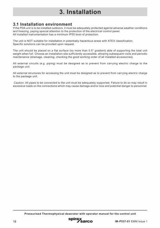
3.1 Installation environmentIf the PDA unit is to be installed outdoors, it must be adequately protected against adverse weather conditions and freezing, paying special attention to the protection of the electrical control panel.All installed instrumentation has a minimum IP55 level of protection.
The unit is NOT suitable for installation in potentially hazardous areas with ATEX classification.Specific solutions can be provided upon request.
The unit should be placed on a flat surface (no more than 0.5° gradient) able of supporting the total unit weight when full. Choose an installation site sufficiently accessible, allowing subsequent visits and periodic maintenance (drainage, cleaning, checking the good working order of all installed accessories).
All external circuits (e.g. piping) must be designed as to prevent from carrying electric charge to the package unit.
All external structures for accessing the unit must be designed as to prevent from carrying electric charge to the package unit.
Caution: All pipes to be connected to the unit must be adequately supported. Failure to do so may result in excessive loads on the connections which may cause damage and/or loss and potential danger to personnel.
3. Installation
IM-P537-01 EMM Issue 1 19
Pressurised Thermophysical deaerator with operator manual for the control unit
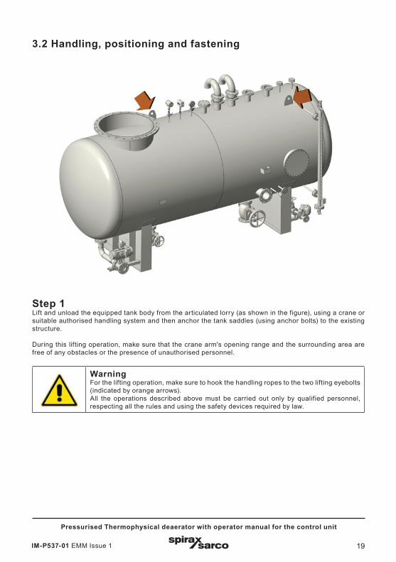
3.2 Handling, positioning and fastening
Step 1Lift and unload the equipped tank body from the articulated lorry (as shown in the figure), using a crane or suitable authorised handling system and then anchor the tank saddles (using anchor bolts) to the existing structure.
During this lifting operation, make sure that the crane arm's opening range and the surrounding area are free of any obstacles or the presence of unauthorised personnel.
Warning For the lifting operation, make sure to hook the handling ropes to the two lifting eyebolts (indicated by orange arrows).All the operations described above must be carried out only by qualified personnel, respecting all the rules and using the safety devices required by law.

IM-P537-01 EMM Issue 120
Pressurised Thermophysical deaerator with operator manual for the control unit
Step 2Lift the deaerator head using a crane or appropriate authorised handling system (yellow arrows), then attach the head to the tank nozzle using tie bolts (green arrow).
IMPORTANT remember to insert the gasket before tightening the anchoring bolts.
During this lifting operation, make sure that the crane arm's opening range and the surrounding area are free of any obstacles or the presence of unauthorised personnel. Finally, fasten the safety valve (red arrow) to the tank nozzle.
Warning For the lifting operation, be sure to hook the handling ropes to the two lifting eyebolts welded to the bottom of the deaerator head (indicated by orange arrows).All the operations described above must be carried out only by qualified personnel, respecting all the rules and using the safety devices required by law.
IM-P537-01 EMM Issue 1 21
Pressurised Thermophysical deaerator with operator manual for the control unit
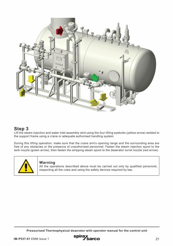
Step 3Lift the steam injection and water inlet assembly skid using the four lifting eyebolts (yellow arrow) welded to the support frame using a crane or adequate authorised handling system.
During this lifting operation, make sure that the crane arm's opening range and the surrounding area are free of any obstacles or the presence of unauthorised personnel. Fasten the steam injection spool to the tank nozzle (green arrow), then fasten the stripping steam spool to the deaerator turret nozzle (red arrow).
Warning All the operations described above must be carried out only by qualified personnel, respecting all the rules and using the safety devices required by law.
IM-P537-01 EMM Issue 122
Pressurised Thermophysical deaerator with operator manual for the control unit
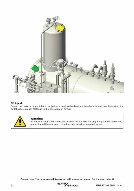
Step 4Fasten the make-up water inlet spool (yellow arrow) to the deaerator head nozzle and then fasten it to the outlet spool, already fastened to the frame (green arrow).
Warning All the operations described above must be carried out only by qualified personnel, respecting all the rules and using the safety devices required by law.
IM-P537-01 EMM Issue 1 23
Pressurised Thermophysical deaerator with operator manual for the control unit
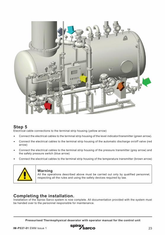
Step 5Electrical cable connections to the terminal strip housing (yellow arrow)
- Connect the electrical cables to the terminal strip housing of the level indicator/transmitter (green arrow).
- Connect the electrical cables to the terminal strip housing of the automatic discharge on/off valve (red arrow)
- Connect the electrical cables to the terminal strip housing of the pressure transmitter (grey arrow) and the safety pressure switch (blue arrow)
- Connect the electrical cables to the terminal strip housing of the temperature transmitter (brown arrow)
Warning All the operations described above must be carried out only by qualified personnel, respecting all the rules and using the safety devices required by law.
Completing the installation. Installation of the Spirax Sarco system is now complete. All documentation provided with the system must be handed over to the personnel responsible for maintenance.
IM-P537-01 EMM Issue 124
Pressurised Thermophysical deaerator with operator manual for the control unit
3.3 Process connections and drainingEach unit is provided with drawings indicating the location and specifications of the connections to be made according with the configuration and options ordered.
Therefore, refer to the dimensional drawing for the specific unit.
In general, Spirax Sarco integrated systems are installed following this simple procedure:
- Note: Before making any connection make sure that all pipes are clean and free from foreign bodies or waste matter. This is usually done by blowing out the pipes with compressed air. Any foreign body or waste matter may impair the functionality or performance of the unit.
- Note: For all pipe connections, the use and/or type of sealant or gaskets at the coupling points must be chosen according to local rules, accepted by common practice, or according to the installer's specifications.
- Note: Manual isolation valves and non-return valves must meet the specifications and requirements of local regulations.
- Steam is a fluid that can be very dangerous due to high temperature and high pressure. Use common sense and follow all recommended procedures when performing installation, commissioning and maintenance to avoid possible accidents.
- Make sure that a manual isolation valve is installed upstream of the steam line (power source), and that it functions properly. If there is any doubt about the integrity of the isolation valve, replace it before starting the installation.
3.3.1 Primary industrial steam line connection.Connect the inlet of the unit's primary steam line to the plant's technological steam distribution network.The manual isolation valve provided on the line must be closed and must remain closed during installation.The exact position of the primary steam inlet connection, as well as the pipe diameter and the size of the connection flange, can be found in the drawings provided with the unit.
3.3.2 Condensate return line connection.Connect the plant’s condensate return line to the condensate inlet provided in the pkg unit. The exact position of the primary steam inlet connection, as well as the pipe diameter and the size of the connection flange, can be found in the drawings provided with the unit.
3.3.3 Make-up water connection.Connect the unit's make-up water line inlet to the plant’s line.The manual isolation valve provided on the line must be closed and must remain closed during installation.The exact position of the make-up water inlet connection, as well as the pipe diameter and the size of the connection flange, can be found in the drawings provided with the unit.
IM-P537-01 EMM Issue 1 25
Pressurised Thermophysical deaerator with operator manual for the control unit
3.3.4 Safety valves connection.Spirax Sarco integrated systems are equipped with one or more safety valves. On the primary side, it is assumed that the safety valve is installed on the deaerator. The connection of the safety valve to a suitable vent and discharge system serves both to prevent damage to the device and to reduce the risk of accidents that may be caused by water. All vents and pipes connected to the safety valve must comply with the regulations in force.
- Do not install a valve between the safety valve and the vent or vent line. This could cause serious damage if the safety valve trips and the manual valve is closed. This situation can cause an excessive increase in pressure in the circuit, which may explode.
- The size of the vent lines of the safety valves must be sufficient and suitable to the operating conditions on site. Maximum back pressure and temperature must be taken into account.
- The safety valves must be installed in such a way that no excessive static or thermal stress is transmitted to the valve from the discharge and drain lines (take into account any reaction forces generated during discharge).
- The discharge lines must be laid in such a way as to facilitate the flow.
- The discharge line of the safety valves must be laid in such a way as to ensure a slope up to the drain hole drilled at the lowest point of the pipe (the size of the drainage hole must be adequate).
- Draining of the discharge line is absolutely necessary in order to prevent the formation of a water head that generates back pressure on the safety valve discharge line.
3.3.5 Draining the generator PDA deaerators are equipped with discharge/drainage with manual valve installed at the bottom of the tank. This valve discharges at the same pressure and operating temperature as the deaerator and it can cause serious physical injury or even death if not properly connected. It is therefore recommended to connect the drainage of the deaerator to the system's discharge network in accordance with the regulations in force.
3.3.6 Other bleeds/vents/drainages (where applicable) PDA units can be equipped with optional systems such as primary steam line drainage system. The drainage of the primary steam line can be directed/transferred into the condensate return line of the plant.
3.4 Pneumatic section connectionThe Spirax Sarco integrated systems are equipped with pneumatic control valves requiring compressed air with calibration ranging from 15 to 100 psi, and on/off valves requiring compressed air with calibration ranges specified in the drawings provided and installation manuals for the specific component. The pneumatic actuators require an air supply pressure of 15 to 100 psi. A reducer filter with pressure gauge is installed on each valve to regulate the supply pressure at the valves. To avoid damaging the pneumatic actuators membrane, it is necessary to check the supply pressure required by each valve.
The procedure for calibration of the reducer filters RF is explained in the user and instruction manual included in the technical file of the project provided with the unit.
For questions not answered in this manual, or if the procedures described are not clearly understood, please contact Spirax Sarco for clarification.
- Ensure that the instrument air supply line has been closed and that the downstream line is not under pressure before starting any connection.
- Note: For all pneumatic connections, the use and/or type of sealant or couplings gaskets must be chosen according to rules accepted by common practice, or according to the installer's specifications.
IM-P537-01 EMM Issue 126
Pressurised Thermophysical deaerator with operator manual for the control unit
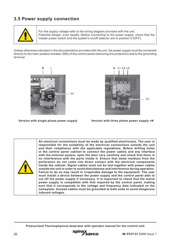
3.5 Power supply connection
For the supply voltage refer to the wiring diagram provided with the unit. Potential danger, even deadly. Before connecting to the power supply, check that the master power switch and the system’s on/off selector are in position 0 (OFF).
Unless otherwise indicated in the documentation provided with the unit, the power supply must be connected directly to the main isolation breaker (MS) of the control panel (removing the protection) and to the grounding terminal.
All electrical connections must be made by qualified electricians. The user is responsible for the suitability of the electrical connections outside the unit and their compliance with the applicable regulations. Before drilling holes in the control panel cabinet to connect the power cables and any interface with the external system, open the door very carefully and check that there is no interference with the parts inside it. Ensure that metal residues from the perforation do not come into direct contact with the electrical components inside the cabinet. Signal cables must not be laid together with power cables outside the unit in order to avoid disturbances and interference during operation. Failure to do so may result in irreparable damage to the equipment. The user must install a device between the power supply and the control panel able to cut off the power supply if necessary. It is important to check that the mains power supply is compatible with that required by the control panel, making sure that it corresponds to the voltage and frequency data indicated on the nameplate. Unused cables must be grounded at both ends to avoid dangerous induced voltages.
Version with single phase power supply Version with three phase power supply +N

IM-P537-01 EMM Issue 1 27
Pressurised Thermophysical deaerator with operator manual for the control unit
Electrical specifications
For electrical data, refer to the wiring diagram provided with the unit. The following are generic electrical data that may not fully match the specific data of the supplied unit.
Control panel power supply - Input voltage: 3x400V + N or 1x230V - 50 Hz 0.5kW (Inst.)
Feedback:- Output contacts: 3 A - 220V for inductive loads
- Output contacts: 6 A - 220V for resistive loads
Operating conditions- Operating ambient temperature: minimum 0 °C,
maximum 50 °C
- Relative humidity (RH): 5% to 95% non-condensing
- LCD display with energy saving dimmer function
Note: If ambient conditions lead to exceeding the maximum temperature inside the control panel cabinet, conditioning devices are available.
Electrical specifications for unit’s components (power supply from the electrical control panel) The unit’s electrical components are supplied wired to the electrical control panel. For electrical specifications see component list in P&ID, wiring diagram, specifications (TI) for each component.
IM-P537-01 EMM Issue 128
Pressurised Thermophysical deaerator with operator manual for the control unit
For the correct execution of the unit commissioning operations, it is recommended to use the support and specific skills of a Spirax Sarco technician, available to you by contacting our Service department
Check the following before starting the deaerator:
- The sealing of the boiler feedwater pumps must be suitable for the thermophysical deaerator operating temperature.
- The NPSH value of the boiler feedwater pumps, to determine the correct height at which the deaerator should be positioned, in order to avoid pump cavitation phenomenon.
- We recommend maintaining a height of not less than 3 metres.
- The possibility of installing the unit inside the boiler house respecting the above considerations. If the necessary space is not available, installation on an external structure can be envisaged, taking into account the weight of the deaerator in operation.
- Check that the condensate has enough pressure to return to the turret.
- Provide room for operation to allow for easy maintenance if not already included in the Spirax Sarco package, insulate the equipment and all "hot" lines of the unit
4.1 Pre-commissioning inspection (initial start-up)In most new installations, dirt is inadvertently collected inside the pipes during construction of the pipes and system installation. It is essential to carefully remove all impurities and residual dirt from inside before starting the commissioning.
- Ensure that all manual isolation valves (on primary steam, condensate drain, clean steam inlet and feedwater) are closed.
- Clean the filters upstream of the control valves.
- Ensure that the drain cock of the device is closed.
- Make sure that the unit power supply is disconnected or shut off upstream.
- Check that the design conditions of the primary steam do not exceed that indicated on the unit's nameplate.
- Check that the make-up water line is pressurised and has been vented.
- Check that the technological (primary) steam line is pressurised and has been drained/vented.
- Check that the pneumatic air line, where required, meets the system requirements.
- Check that the power supply complies with the system requirements.
- Perform a double check to ensure that all connections to steam, condensate and water lines are correctly made.
- Check that the bolts of the flanged connections are properly tightened.
- Check all electrical connections, both outside and inside the unit, making sure that they comply with the wiring diagram (see wiring diagram provided with the unit).
- Check the pneumatic air supply of the valve filters/reducers (if provided pneumatically actuated) and that it complies with the system requirements.
4. Commissioning

IM-P537-01 EMM Issue 1 29
Pressurised Thermophysical deaerator with operator manual for the control unit
4.1.1 Cleaning before commissioning Before commissioning a new unit, it is recommended to flush the deaerator tank or carry out other procedures required by the operating or plant regulations.
4.2 Commissioning procedure - Ensure that all isolation valves are closed.
- Ensure that the master switch and the system’s start-up selector on the control panel are set to 0/OFF.
- Ensure that the emergency button is released.
- Connect or restore the power supply to the unit's control panel.
- Switch on the control panel using the master switch (set to 1/ON).
- Check the parameters set on the programmable logic controller (PLC). Set process specific parameters such as the pressure, level and temperature specific parameters (SP).
- Ignore potential low level alarm and, where necessary, reset other alarms using the block reset button.
- The make-up water control valve begins to modulate. Wait for the automatic loading of the deaerator up to the SP level (the low level alarm will automatically reset when the minimum level threshold is exceeded).
- Open the isolation valves on the primary steam line drainage assembly (where the option is available).
- Open the isolation valve on the condensate drain line.
- Slowly open the primary steam isolation valve.
- Wait until the upper limit of the heating ramp and the SP pressure are reached by modulating the primary steam control valve.
Note: Leakage from flanged or threaded connections may occur during loading the water and the heating/pressurisation phase of the deaerator and lines. This is normal, especially on the steam and water side due to the characteristics of the seals used (PTFE). Therefore, the procedure is to let the seals settle and carefully tighten the connections.
IM-P537-01 EMM Issue 130
Pressurised Thermophysical deaerator with operator manual for the control unit
4.3 Procedure for decommissioning (shut-down) The following procedure must be followed if the deaerator is switched off for longer periods of time, such as the weekend, or for maintenance purposes.
- Close the primary fluid isolation valve.
- Stop the unit operation: set selector 1-0-REM to 0.
- Wait for pressure to drop to approx. 0 bar. To accelerate the process, slightly open the drain cock valve of the deaerator with the system still operating and primary steam shut off. The level will be automatically restored with cold water, cooling the deaerator faster. Then shut off the system.
- Close the isolation valve on the make-up water line
- Close all other isolation valves
- Allow to cool and then drain the deaerator completely through the drainage valve.
- Switch off the control panel using the master switch (0/OFF) and disconnect the power supply upstream.
- After prolonged shut-down of the assembly, it is recommended to completely empty the deaerator and follow the procedures required by the user's plant downtime regulations.
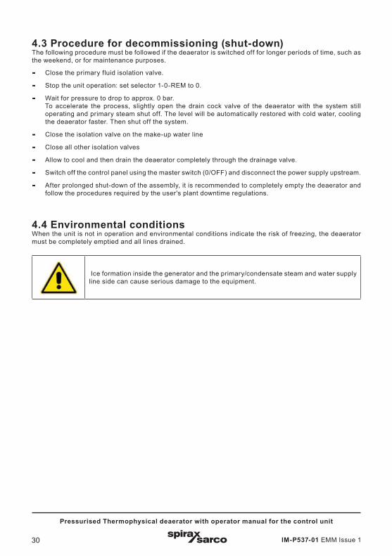
4.4 Environmental conditions When the unit is not in operation and environmental conditions indicate the risk of freezing, the deaerator must be completely emptied and all lines drained.
Ice formation inside the generator and the primary/condensate steam and water supply line side can cause serious damage to the equipment.
IM-P537-01 EMM Issue 1 31
Pressurised Thermophysical deaerator with operator manual for the control unit
5.1 Operation The PDA deaerator unit consists of a complete, safe and functional package system able to eliminate the gases dissolved in the feedwater of steam generators.
The deaeration system operates as follows:- The condensate and make-up water are fed into the upper part of the deaerator head, are mixed and fall
on a series of plates with which the turret has been sized. The amount of make-up water is regulated by an actuated valve (pneumatic or electric), depending on the level set point.
- The steam fed into the system is divided into two circuits:
- stripping steam fed into the lower part of the deaerator head
- tempering steam introduced through an injection pipe into the main body of the deaerator
A pressure reduction valve is installed on the steam circuit inlet line, which allows the pressure and relative temperature to be maintained in the conditions defined in the design phase based on system data.
- The thermophysical deaerator includes a series of safety devices, such as:
- safety valves
- check valves with vacuum breaker function
- automatic overflow drain cock
- assembly with discharger for mechanical leakage
- safety pressure switch for high pressure
- level transmitter with limit switch for high and low level contacts
- The venting of the non-condensable gases is done through the vent valve located on top of the deaerator turret
For a good thermophysical deaeration it is necessary:1. Heat the water to a temperature close to the saturation temperature. However, the saturation temperature
alone does not ensure complete gas removal.
2. It is important to spray the water as wide as possible to increase the surface area so that it exceeds the surface tension and viscosity that retains dissolved gases.
3. Reduce the distance the dissolved gases have to travel within the water, while also intensifying the heating process.
4. Ensure that the time allotted to the first three activities is sufficient for deaeration.
5. Ensure that the released gases have a chance to escape the cycle throughout the entire deaeration process.
6. Maintain a balanced dynamic process. The deaeration process must maintain a constant vapour pressure in the system in order to be effective. Large load fluctuations can adversely affect the water deaeration process.
The unit is fully automatic and equipped with a control panel.The main controls of the unit are the pressure, temperature and water level inside the deaerator tank. These controls are interlocked by always active (both in automatic and manual adjustment mode) electromechanical protections on the unit panel, according to the regulations in force.
5. Operation
IM-P537-01 EMM Issue 132
Pressurised Thermophysical deaerator with operator manual for the control unit
5.1.1 Pressure regulation The pressure of the deaerator is maintained by the related pressure regulator (PIC-01) of the PLC control unit. The process variable is detected by the gauge pressure transmitter (PT-01) installed on the deaerator body, which sends the 4-20 mA signal, corresponding to the 0-2.5 bar range, to the regulator/PLC which controls the stripping steam valve of the deaerator head.
The control valve is interlocked by the high pressure (PSH-01) and low level (LSL-01) protection devices, which safely close the primary fluid control valve when triggered and stop the heating process. The control valve is "fail-safe" (normally closed, N.C.) and closes in case of interlocking due to alarm, system off, absence of electrical or pneumatic power supply (where applicable).
5.1.2 Temperature control The temperature of the deaerator is maintained by the corresponding temperature controller (TIC-01) of the PLC control unit. The process variable is detected by the temperature transmitter (TT-01) installed on the deaerator body, which sends the 4-20 mA signal, corresponding to the 0-2.5 bar range, to the regulator/PLC that controls the tempering steam valve of the deaerator tank.
The control valve is interlocked by the high pressure (PSH-01) and low level (LSL-01) protection devices, which safely close the primary fluid control valve when triggered and stop the heating process. The control valve is "fail-safe" (N.C.) and closes in case of interlocking due to alarm, system off, absence of electrical or pneumatic power supply (where applicable).
5.1.3 Water level controlThe water level of the deaerator is maintained by the corresponding regulator (LIC-01) of the PLC control unit. The process variable is detected by the level transmitter (LT-01) installed on the deaerator tank, which sends the 4-20 mA signal, corresponding to the range set for the regulator/PLC. The level controller/PLC logic controller processes the PV signal and transmits the 4-20 mA control signal to the feedwater control valve The level control is modulating. The control operates with opposite effects, as the level increases, the opening of the make-up water valve narrows and therefore the water load decreases - and vice versa.
The control valve is interlocked by the high pressure (PSH01) and high level (LSH-01) protection devices, which safely close the water control valve when triggered, shutting off the supply.
The control valve is "fail-safe" (N.C.) and closes in case of interlocking due to alarm, system off, absence of electrical or pneumatic power supply (where applicable).
5.1.4 Product features and specifications.The dimensioning of the device, its intended use, its functionalities and the resulting services depend on the data transmitted by the Customer.
The mechanical-structural design of the device is executed based on the initial data received from the Customer.
The suitability of the device with regard to its service and the context in which it will be used are the responsibility of the User.
IM-P537-01 EMM Issue 1 33
Pressurised Thermophysical deaerator with operator manual for the control unit
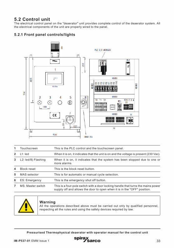
5.2 Control unitThe electrical control panel on the "deaerator" unit provides complete control of the deaerator system. All the electrical components of the unit are properly wired to the panel.
5.2.1 Front panel controls/lights
1 Touchscreen This is the PLC control and the touchscreen panel.
2 L1: led When it is on, it indicates that the unit is on and the voltage is present (230 Vac).
3 L2: led/8) Flashing When it is on, it indicates that the system has been stopped due to one or more alarms.
4 Block reset This is the block reset button.
5 MAS selector This is for automatic or manual cycle selection.
6 ES: Emergency This is the emergency shut off button.
7 MS: Master switch This is a four-pole switch with a door locking handle that turns the mains power supply off and allows the door to open when it is in the "OFF" position.
Warning All the operations described above must be carried out only by qualified personnel, respecting all the rules and using the safety devices required by law.
IM-P537-01 EMM Issue 134
Pressurised Thermophysical deaerator with operator manual for the control unit
5.2.2 Auxiliary circuit protectionThe auxiliary circuit is protected against overloads by a circuit breaker. Each solenoid valve or actuated valve is also protected by a fuse on corresponding terminals panel.
5.2.3 Protection interlocks The electromechanical protections with partial/total system interlocks are the following:
- High pressure → closes primary steam control valves for pressure (YY1), temperature (YY2) and Shut Off Steam (YY05) (optional) (requires manual reset if set in PLC);
- Low level→ closes primary steam control valves for pressure (YY1), temperature (YY2) and Shut Off Steam (YY05) (optional) (requires manual reset if set in PLC);
- High level → closes the water control valve (YY3), blocking the feed and controls the OVERFLOW valve (YY04) (timed control);
- External alarm or consent denied (if used) → closes all control valves, shutting off or stopping heating/pressurising and water supply.
In addition, the system is protected against the following events:
- Blackout (or sudden panel shut-down/emergency shut-down pressed) → the control valves (primary steam and feedwater), both pneumatically and electrically actuated, are fail-safe (N.C.). Therefore, in the event of a power failure, they return to the safety position (closed), shutting off the supply of technological steam and feedwater. After a blackout, the system is prepared to be restarted manually. This functionality can be changed (automatic restart), via the PLC
- Pneumatic air supply shut off (or low pressure) → where pneumatically actuated control valves are provided, the pneumatic supply shut off or insufficient pressure, closes or limits the opening of the control valves, shutting off or limiting the supply of primary steam and feedwater. Insufficient pneumatic air pressure, even temporarily, could cause control instability or may set off alarms
5.2.3 Digital I/Os For a possible basic interfacing with the external automation, the following digital I/Os are commonly supplied (all versions):
- DI: Start system remotely (with mode selector set to REM): stable contact (closed = start) -
- DI: consent/external block: stable contact (closed = OK, open = block) -
- DI: possible external pump in motion
- DO: System feedback in operation: SPDT contact -
- DO: voltage presence feedback: SPDT contact -
- DO: cumulative alarm feedback: SPDT contact
- DO possible external pump control
5.2.4 Communication interface (serial bus) Units equipped with PLC logic control can be prepared for interfacing with external monitoring/control system via serial bus. The available communication protocols are listed in the technical specification of the product. Refer to the additional documentation provided with the unit for the supplied protocol specifications, interfacing instructions and address register.
IM-P537-01 EMM Issue 1 35
Pressurised Thermophysical deaerator with operator manual for the control unit
5.2.5 Terminal block A terminal block is housed inside the panel for wiring of:
- electronic components on pre-wired unit panel
- digital I/Os
- analogue I/Os The power supply (from the mains) must be connected directly to the master switch terminals, unless otherwise indicated in the documentation provided with the unit. The serial bus communication link (where applicable) must be made directly to the PLC communication port
5.2.6 Control functionsControl panels with PLC logic offer features such as: synoptic on 7" touchscreen panel with process data, user-friendly interface, PV trend, alarm history, interfacing with external automation via serial bus, such as MODBUS TCP/IP, Modbus RTU, Bacnet IP, Bacnet MSTP, Profibus DP and Profinet, all in SLAVE mode.
Other PLC solutions can be provided upon request, as well as other communication protocols (subject to feasibility).
IM-P537-01 EMM Issue 136
Pressurised Thermophysical deaerator with operator manual for the control unit
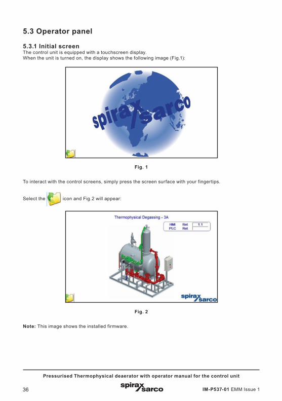
5.3 Operator panel
5.3.1 Initial screenThe control unit is equipped with a touchscreen display.When the unit is turned on, the display shows the following image (Fig.1):
Fig. 1
To interact with the control screens, simply press the screen surface with your fingertips.
Select the icon and Fig.2 will appear:
Fig. 2
Note: This image shows the installed firmware.
IM-P537-01 EMM Issue 1 37
Pressurised Thermophysical deaerator with operator manual for the control unit
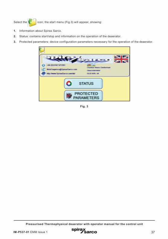
Select the icon; the start menu (Fig.3) will appear, showing:
1. Information about Spirax Sarco.
2. Status: contains start/stop and information on the operation of the deaerator.
3. Protected parameters: device configuration parameters necessary for the operation of the deaerator.
Fig. 3

IM-P537-01 EMM Issue 138
Pressurised Thermophysical deaerator with operator manual for the control unit
5.3.2 Protected parameters
Pressing the PROTECTED PARAMETERS icon, Fig.4 will appear.
Fig.4
Enter Password = 3. then press ENTER to confirm.
When you enter, Fig.5 will appear.
Fig.5

IM-P537-01 EMM Issue 1 39
Pressurised Thermophysical deaerator with operator manual for the control unit
Pressing the Machine Settings icon, Fig.6 will appear.
Press the icon to change
the settings (the lock opens).
Then use the side buttons to
enable or disable the
displayed functions.
When the configuration is
complete, press the icon
to save the settings (the lock closes).
It is possible to display the total running time of the pumps.
Then press the button to
return to the previous screen (Fig. 5).
Fig.6
IM-P537-01 EMM Issue 140
Pressurised Thermophysical deaerator with operator manual for the control unit
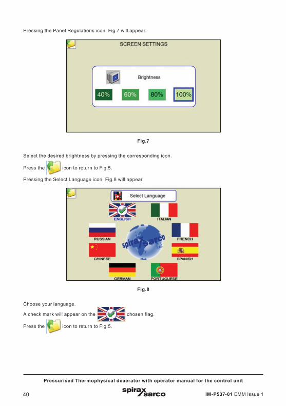
Pressing the Panel Regulations icon, Fig.7 will appear.
Fig.7
Select the desired brightness by pressing the corresponding icon.
Press the icon to return to Fig.5.
Pressing the Select Language icon, Fig.8 will appear.
Fig.8
Choose your language.
A check mark will appear on the chosen flag.
Press the icon to return to Fig.5.

IM-P537-01 EMM Issue 1 41
Pressurised Thermophysical deaerator with operator manual for the control unit
Pressing the Date & Time icon, Fig.9 will appear.
Fig.9
Press the respective Day/Month/Year and Hours/Minutes/Seconds boxes to set the current date and time.If you want to automatically update the time during the change between daylight saving and summer time and vice versa, press the white box.
The check mark will confirm your choice.
Then press the button to return to the previous screen (Fig. 5).
Pressing the I/O Status icon, Fig.10a will appear.
Fig.10a
When the deaerator is not active (DEGASSING IN MANUAL), it is possible to force the output status by pressing the associated icon (it becomes green); to reset the command press the corresponding icon again.To control the modulating valve, press on the valve and set the desired valve opening percentage; to reset the control press on the corresponding icon again.
IM-P537-01 EMM Issue 142
Pressurised Thermophysical deaerator with operator manual for the control unit
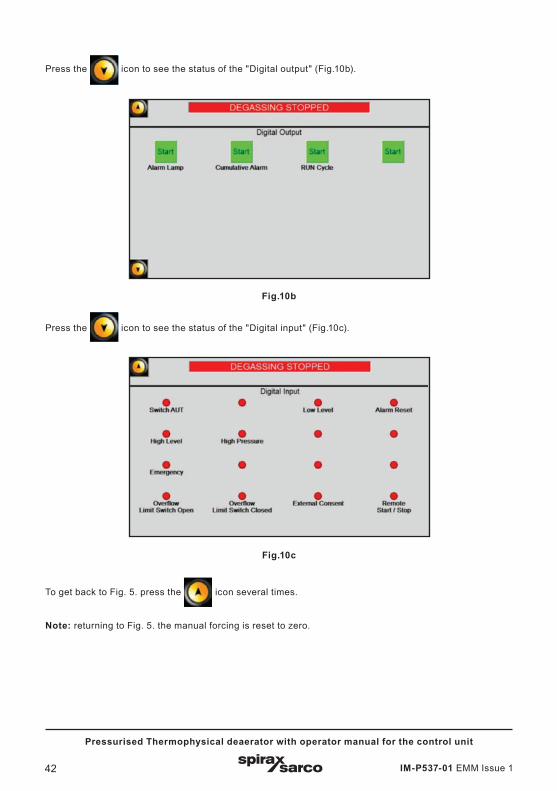
Press the icon to see the status of the "Digital output" (Fig.10b).
Fig.10b
Press the icon to see the status of the "Digital input" (Fig.10c).
Fig.10c
To get back to Fig. 5. press the icon several times.
Note: returning to Fig. 5. the manual forcing is reset to zero.
IM-P537-01 EMM Issue 1 43
Pressurised Thermophysical deaerator with operator manual for the control unit
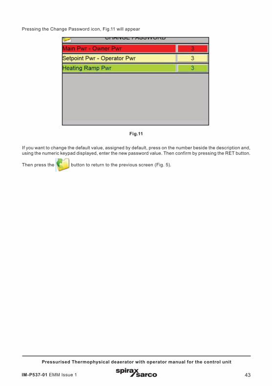
Pressing the Change Password icon, Fig.11 will appear
Fig.11
If you want to change the default value, assigned by default, press on the number beside the description and, using the numeric keypad displayed, enter the new password value. Then confirm by pressing the RET button.
Then press the button to return to the previous screen (Fig. 5).
IM-P537-01 EMM Issue 144
Pressurised Thermophysical deaerator with operator manual for the control unit
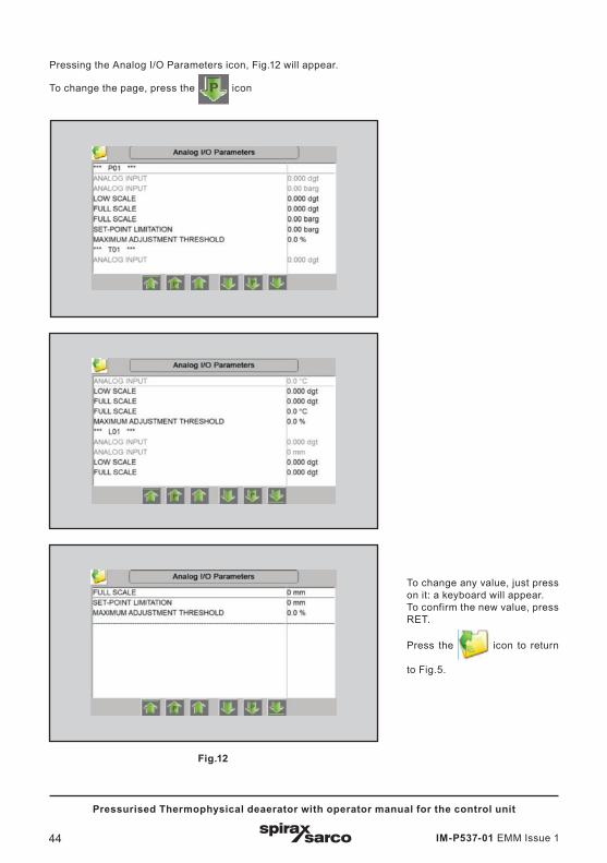
Fig.12
Pressing the Analog I/O Parameters icon, Fig.12 will appear.
To change the page, press the icon
To change any value, just press on it: a keyboard will appear.To confirm the new value, press RET.
Press the icon to return
to Fig.5.
IM-P537-01 EMM Issue 1 45
Pressurised Thermophysical deaerator with operator manual for the control unit
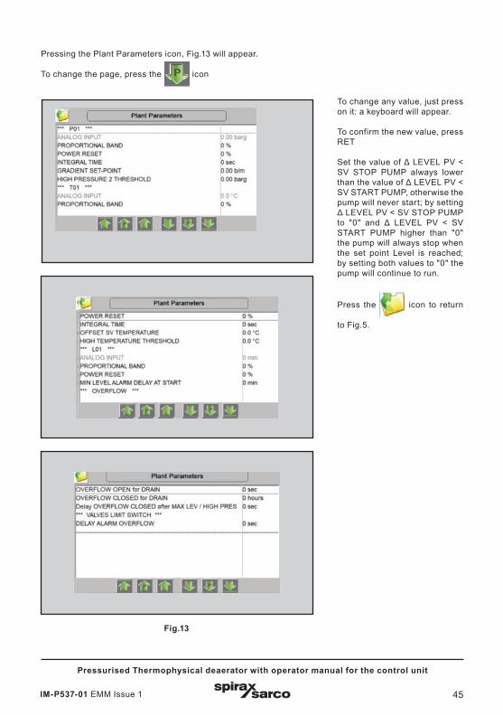
Fig.13
Pressing the Plant Parameters icon, Fig.13 will appear.
To change the page, press the icon
To change any value, just press on it: a keyboard will appear.
To confirm the new value, press RET
Set the value of Δ LEVEL PV < SV STOP PUMP always lower than the value of Δ LEVEL PV < SV START PUMP, otherwise the pump will never start; by setting Δ LEVEL PV < SV STOP PUMP to "0" and Δ LEVEL PV < SV START PUMP higher than "0" the pump will always stop when the set point Level is reached; by setting both values to "0" the pump will continue to run.
Press the icon to return
to Fig.5.
IM-P537-01 EMM Issue 146
Pressurised Thermophysical deaerator with operator manual for the control unit
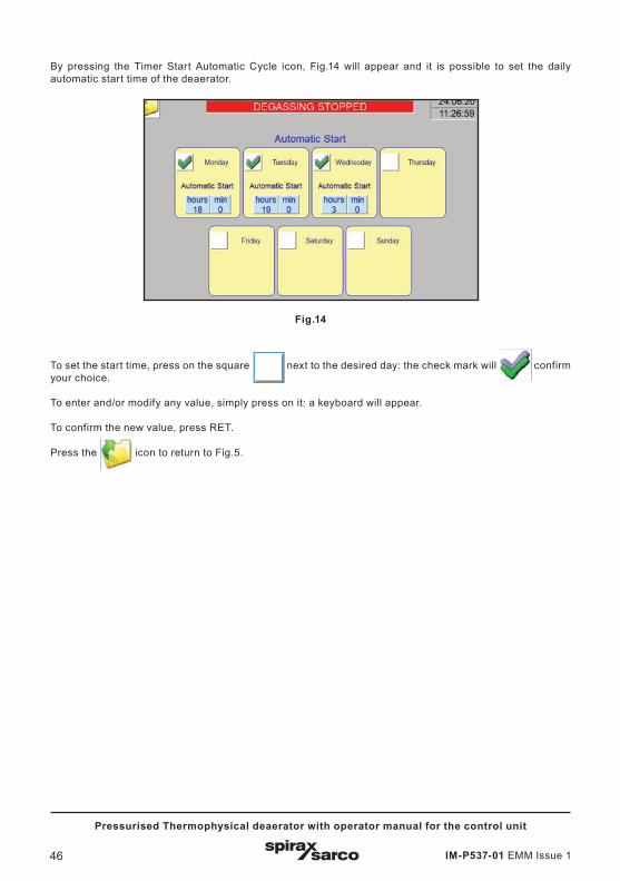
By pressing the Timer Start Automatic Cycle icon, Fig.14 will appear and it is possible to set the daily automatic start time of the deaerator.
Fig.14
To set the start time, press on the square next to the desired day: the check mark will confirm your choice.
To enter and/or modify any value, simply press on it: a keyboard will appear.
To confirm the new value, press RET.
Press the icon to return to Fig.5.
IM-P537-01 EMM Issue 1 47
Pressurised Thermophysical deaerator with operator manual for the control unit
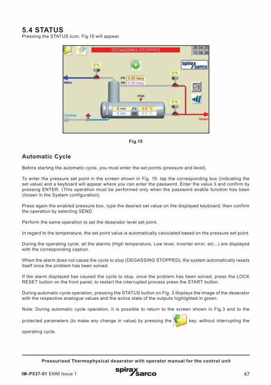
5.4 STATUS Pressing the STATUS icon, Fig.15 will appear.
Fig.15
Automatic Cycle
Before starting the automatic cycle, you must enter the set points (pressure and level).
To enter the pressure set point in the screen shown in Fig. 15. tap the corresponding box (indicating the set value) and a keyboard will appear where you can enter the password. Enter the value 3 and confirm by pressing ENTER. (This operation must be performed only when the password enable function has been chosen in the System configuration).
Press again the enabled pressure box, type the desired set value on the displayed keyboard; then confirm the operation by selecting SEND.
Perform the same operation to set the deaerator level set point.
In regard to the temperature, the set point value is automatically calculated based on the pressure set point.
During the operating cycle, all the alarms (High temperature, Low level, Inverter error, etc...) are displayed with the corresponding caption.
When the alarm does not cause the cycle to stop (DEGASSING STOPPED), the system automatically resets itself once the problem has been solved.
If the alarm displayed has caused the cycle to stop, once the problem has been solved, press the LOCK RESET button on the front panel; to restart the interrupted process press the START button.
During automatic cycle operation, pressing the STATUS button on Fig. 3 displays the image of the deaerator with the respective analogue values and the active state of the outputs highlighted in green.
Note: During automatic cycle operation, it is possible to return to the screen shown in Fig.3 and to the
protected parameters (to make any change in value) by pressing the key, without interrupting the
operating cycle.
IM-P537-01 EMM Issue 148
Pressurised Thermophysical deaerator with operator manual for the control unit
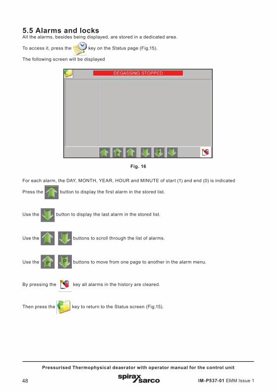
5.5 Alarms and locksAll the alarms, besides being displayed, are stored in a dedicated area.
To access it, press the key on the Status page (Fig.15).
The following screen will be displayed
Fig. 16
For each alarm, the DAY, MONTH, YEAR, HOUR and MINUTE of start (1) and end (0) is indicated
Press the button to display the first alarm in the stored list.
Use the button to display the last alarm in the stored list.
Use the buttons to scroll through the list of alarms.
Use the buttons to move from one page to another in the alarm menu.
By pressing the key all alarms in the history are cleared.
Then press the key to return to the Status screen (Fig.15).
IM-P537-01 EMM Issue 1 49
Pressurised Thermophysical deaerator with operator manual for the control unit
In detail for the operating cycle of the deaerator:
Block of the DG feedwater valve when one of the following alarms occurs:
- analogue DG level transmitter error
- maximum DG level
Block the DG pressure and temperature control valves when one of the following alarms occurs:
- analogue DG temperature transmitter error
- analogue DG pressure transmitter error
- analogue DG level transmitter error
- minimum DG level
Pressing the emergency button during automatic operation will stop the cycle: all active functions will be cancelled and the corresponding alarm will be activated.
To resume automatic operation set the emergency button in stand-by position and press the START button: the cycle will restart.
IM-P537-01 EMM Issue 150
Pressurised Thermophysical deaerator with operator manual for the control unit
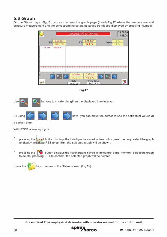
Fig.17
Use buttons to shorten/lengthen the displayed time interval.
By using keys, you can move the cursor to see the set/actual values at
a certain time.
With STOP operating cycle:
- pressing the button displays the list of graphs saved in the control panel memory: select the graph to display, pressing RET to confirm, the selected graph will be shown.
- pressing the button displays the list of graphs saved in the control panel memory: select the graph to delete, pressing RET to confirm, the selected graph will be deleted.
Press the key to return to the Status screen (Fig.15).
5.6 GraphOn the Status page (Fig.15), you can access the graph page (trend) Fig.17 where the temperature and pressure measurement and the corresponding set point values trends are displayed by pressing symbol.
IM-P537-01 EMM Issue 1 51
Pressurised Thermophysical deaerator with operator manual for the control unit
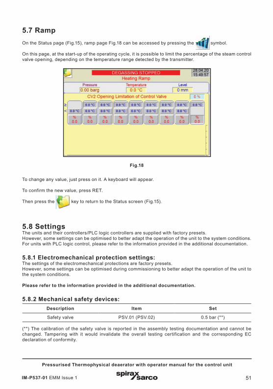
5.7 Ramp On the Status page (Fig.15), ramp page Fig.18 can be accessed by pressing the symbol.
On this page, at the start-up of the operating cycle, it is possible to limit the percentage of the steam control valve opening, depending on the temperature range detected by the transmitter.
Fig.18
To change any value, just press on it. A keyboard will appear.
To confirm the new value, press RET.
Then press the key to return to the Status screen (Fig.15).
5.8 Settings The units and their controllers/PLC logic controllers are supplied with factory presets. However, some settings can be optimised to better adapt the operation of the unit to the system conditions. For units with PLC logic control, please refer to the information provided in the additional documentation.
5.8.1 Electromechanical protection settings: The settings of the electromechanical protections are factory presets. However, some settings can be optimised during commissioning to better adapt the operation of the unit to the system conditions.
Please refer to the information provided in the additional documentation.
5.8.2 Mechanical safety devices: Description Item Set
Safety valve PSV.01 (PSV.02) 0.5 bar (**) (**) The calibration of the safety valve is reported in the assembly testing documentation and cannot be changed. Tampering with it would invalidate the overall testing certification and the corresponding EC declaration of conformity.
IM-P537-01 EMM Issue 152
Pressurised Thermophysical deaerator with operator manual for the control unit
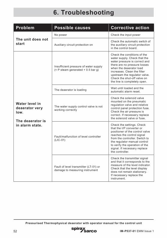
6. Troubleshooting
Problem Possible causes Corrective action
The unit does not start
No power Check the input power
Auxiliary circuit protection onCheck the automatic switch of the auxiliary circuit protection in the control board.
Water level in deaerator very low.
The deaerator is in alarm state.
Insufficient pressure of water supply(< P steam generated + 0.5 bar g)
Check the conditions of the water supply. Check that the water pressure is correct and there are no pressure losses when the deaerator load increases. Clean the filter upstream the regulator valve. Check the shut-off valve on the line is completely open.
The deaerator is loading Wait until loaded and the automatic alarm reset.
The water supply control valve is not working correctly
Check the solenoid valve mounted on the pneumatic regulation valve and relative control panel protection fuse. Check the air pressure is correct. If necessary replace the solenoid valve or fuse.
Fault/malfunction of level controller (LIC-01)
Check the settings. Check that the I/P converter or positioner of the control valve reaches the control signal from the controller. Switch to the regulator manual control to verify the operation of the signal. If necessary replace the controller.
Fault of level transmitter (LT-01) or damage to measuring instrument
Check the transmitter signal and that it corresponds to the measure of the level indicator. Check that the level display does not remain stationary. If necessary replace the instrument.
IM-P537-01 EMM Issue 1 53
Pressurised Thermophysical deaerator with operator manual for the control unit
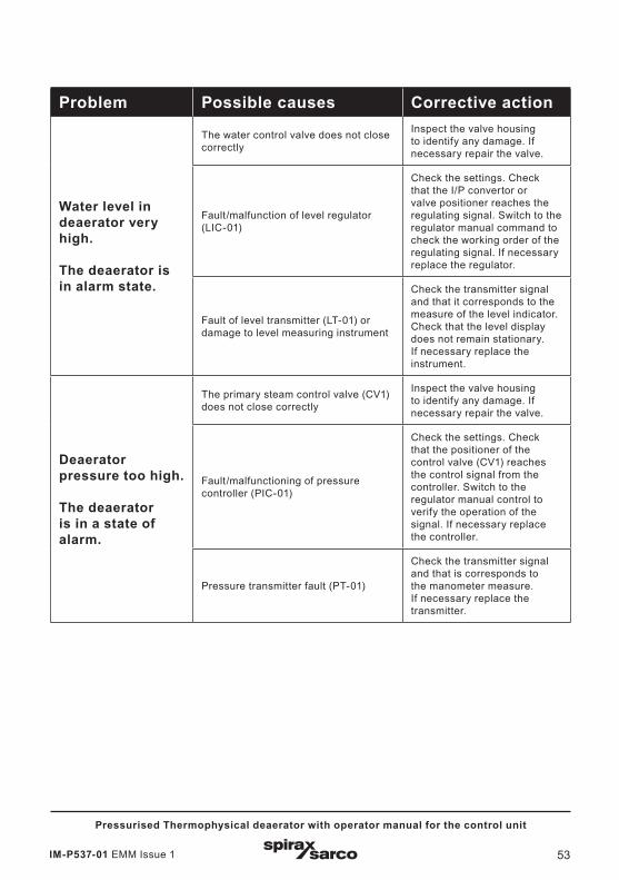
Problem Possible causes Corrective action
Water level in deaerator very high.
The deaerator is in alarm state.
The water control valve does not close correctly
Inspect the valve housing to identify any damage. If necessary repair the valve.
Fault/malfunction of level regulator (LIC-01)
Check the settings. Check that the I/P convertor or valve positioner reaches the regulating signal. Switch to the regulator manual command to check the working order of the regulating signal. If necessary replace the regulator.
Fault of level transmitter (LT-01) or damage to level measuring instrument
Check the transmitter signal and that it corresponds to the measure of the level indicator. Check that the level display does not remain stationary. If necessary replace the instrument.
Deaerator pressure too high.
The deaerator is in a state of alarm.
The primary steam control valve (CV1) does not close correctly
Inspect the valve housing to identify any damage. If necessary repair the valve.
Fault/malfunctioning of pressure controller (PIC-01)
Check the settings. Check that the positioner of the control valve (CV1) reaches the control signal from the controller. Switch to the regulator manual control to verify the operation of the signal. If necessary replace the controller.
Pressure transmitter fault (PT-01)
Check the transmitter signal and that is corresponds to the manometer measure. If necessary replace the transmitter.
IM-P537-01 EMM Issue 154
Pressurised Thermophysical deaerator with operator manual for the control unit
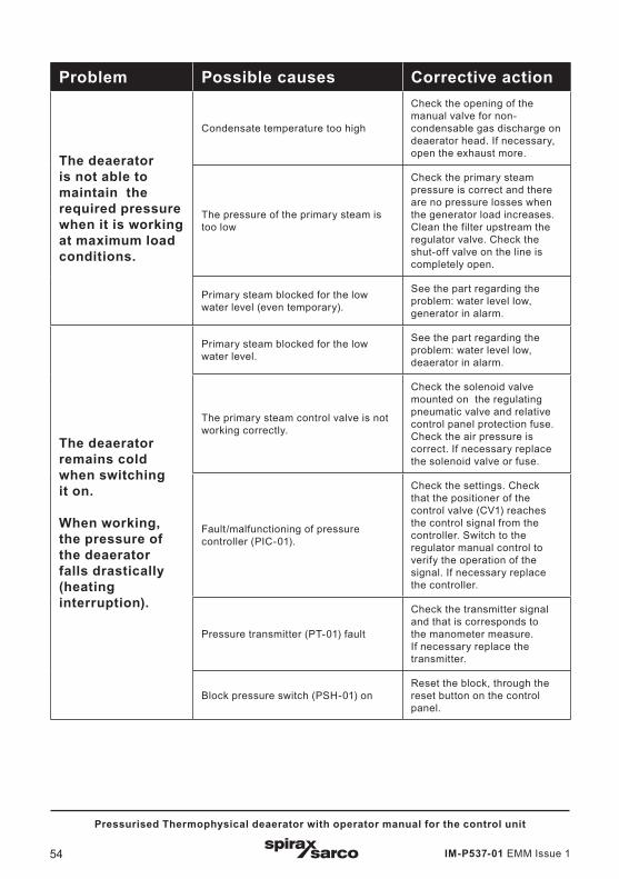
Problem Possible causes Corrective action
The deaerator is not able to maintain the required pressure when it is working at maximum load conditions.
Condensate temperature too high
Check the opening of the manual valve for non-condensable gas discharge on deaerator head. If necessary, open the exhaust more.
The pressure of the primary steam is too low
Check the primary steam pressure is correct and there are no pressure losses when the generator load increases. Clean the filter upstream the regulator valve. Check the shut-off valve on the line is completely open.
Primary steam blocked for the low water level (even temporary).
See the part regarding the problem: water level low, generator in alarm.
The deaerator remains cold when switching it on.
When working, the pressure of the deaerator falls drastically (heating interruption).
Primary steam blocked for the low water level.
See the part regarding the problem: water level low, deaerator in alarm.
The primary steam control valve is not working correctly.
Check the solenoid valve mounted on the regulating pneumatic valve and relative control panel protection fuse. Check the air pressure is correct. If necessary replace the solenoid valve or fuse.
Fault/malfunctioning of pressure controller (PIC-01).
Check the settings. Check that the positioner of the control valve (CV1) reaches the control signal from the controller. Switch to the regulator manual control to verify the operation of the signal. If necessary replace the controller.
Pressure transmitter (PT-01) fault
Check the transmitter signal and that is corresponds to the manometer measure. If necessary replace the transmitter.
Block pressure switch (PSH-01) onReset the block, through the reset button on the control panel.
IM-P537-01 EMM Issue 1 55
Pressurised Thermophysical deaerator with operator manual for the control unit
The information in this section covers service and maintenance procedures for the inspection and replacement of Spirax Sarco system components.
If any maintenance procedures are unclear, please contact Spirax Sarco, having the unit's model and factory number on hand.
Before starting any maintenance work, carefully read the general safety information in chapter 1 of this document.
Ensure that the power supply is shut off before starting any installation or maintenance work.
Many maintenance procedures require the unit to be isolated from the system.
The unit can be re-inserted in the system only after all procedures have been completed.
We recommend that maintenance personnel follow the shut-down and start-up procedures described in this manual.
7.1 General informationThe maintenance of the individual components making up the system must be carried out according to theindividual Installation and Maintenance (IM) manuals.
7.1.1 Replacing componentsAny part of the unit connected in any way to the component to be replaced must be carefully examined before starting the maintenance procedure. We recommend the replacement of all components showing signs of wear or improper operation to prevent system malfunction.
7.1.2 Electrical connections - rewiringWhen working on live components, carefully follow the steps below:The combination of electr icity, steam and water is very dangerous. Switch of f/disconnect all electricalconnections before any maintenance procedure.
1. Follow the shut-down steps procedure before working on the electrical system.
2. After ensuring that the electrical connection has been shut-down, disconnect and rewire the electrical connection in question.
3. Restore the electrical connection and check that the rewired component is working properly.
4. Follow the start-up procedure described in this manual to restore operation of the device.
7. Maintenance
IM-P537-01 EMM Issue 156
Pressurised Thermophysical deaerator with operator manual for the control unit
7.1.3 Pneumatic connections (instrument air)To work on pneumatically powered components, follow the steps below:The compressed air used in pneumatic systems may have pressures in excess of 150 psi. Compressed air at such pressure can be very dangerous; ensure that the air supply is shut off and that there is no pressure in the line before establishing any connection.
1. Follow the shut-down procedure steps to work on the pneumatic system.
2. After ensuring that the air supply is shut off, disconnect the line and repair the air connection in question.
3. Start the air and check if the reconnected component is working properly.
4. Follow the start-up procedure described in this manual to restore operation.
7.1.4 Control panel - possible check and replacement.The control panel cabinet may include (where provided) communication with a higher system (DCS).The control system is designed to secure the system in case of major alarms and malfunctions. This is done through the safety logic controller provided in the control panel. The system requires electrical power to operate and therefore the system is locked when there is no power.If it is strictly necessary for the unit to remain in operation during power failure, the system must be connected to an emergency power system.Attention: the installer and/or the operator is/are responsible for ensuring that this configuration corresponds to the regulations in force in terms of system safety.If the safety system does not work and needs to be replaced, follow the following procedures. The assembly drawing provided with the unit gives an exact location and any interlocks with other components. Follow the instructions in these documents before removing or replacing a control valve.Steam or water can be very dangerous because of high temperatures and pressure. To avoid possible accidents, use common sense and follow all rules and procedures when performing any maintenance, service or installation.The simultaneous presence of power, steam and water can lead to highly dangerous situations. Turn off the power supply before carrying out any maintenance work.
1. Follow the shut-down procedures before replacing the component.
2. Turn off the power supply and disconnect the connection to the defective component.
3. Following the instructions to remove the component.
It may be necessary to shut off other lines in order to intervene.
4. Install the new component.
5. Carefully reconnect all previously disconnected lines. Power up the system.
6. Follow the start-up procedures to restart the system. Check connections for possible leaks.
7.2 Replacement partsIf not offered when purchasing the product, please contact the Spirax Sarco Service for recommended replacement parts necessary for maintenance.
Replaceable parts may vary depending on the unit and particular design specifications.For information regarding replaceable parts of the unit, refer to the design specifications, or contact Spirax Sarco.
Always provide the model and factory number when contacting Spirax Sarco.

IM-P537-01 EMM Issue 1 57
Pressurised Thermophysical deaerator with operator manual for the control unit
7.3 Appendix A.Bolt tightening procedure
Sequential order
Rotational order
Sequential order
Rotational order
1 - 2 1 1 - 2 13 - 4 5 3 - 4 55 - 6 3 5 - 6 97 - 8 7 7 - 8 3
2 9 - 10 76 11 - 12 114 28 6
104812
Sequential order
Rotational order
Sequential order
Rotational order
1 - 2 1 1 - 2 13 - 4 5 3 - 4 135 - 6 3 5 - 6 57 - 8 7 7 - 8 17
9 - 10 2 9 - 10 911 - 12 6 11 - 12 313 - 14 4 13 - 14 1515 - 16 8 15 - 16 7
17 - 18 1919 - 20 11
2146
18104
168
2012
8 bolts 12 bolts
16 bolts 20 bolts
IM-P537-01 EMM Issue 158
Pressurised Thermophysical deaerator with operator manual for the control unit
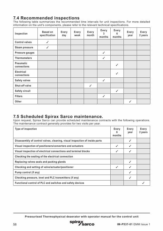
7.4 Recommended inspections The following table summarizes the recommended time intervals for unit inspections. For more detailed information on the unit's components, please refer to the relevant technical specifications.
Inspection Based on specification
Every day
Every week
Every month
Every3
months
Every6
months
Every year
Every2 years
Control valves
Steam pressure
Pressure gauges
Thermometers
Pneumatic connections
Electrical connections
Safety valves
Shut-off valve
Safety circuit
Filters
Other
7.5 Scheduled Spirax Sarco maintenance.Upon request, Spirax Sarco can provide scheduled maintenance contracts with the following operations. The maintenance contract generally provides for two visits per year.
Type of inspection Every 6
months
Every year
Every2 years
Disassembly of control valves, cleaning, visual inspection of inside parts
Visual inspection of positioners/converters and actuators
Visual inspection of electrical connections and terminal blocks
Checking the sealing of the electrical connection
Replacing valves seals and packing glands
Checking and setting of valve/actuator/positioner
Pump control (if any)
Checking pressure, level and PLC transmitters (if any)
Functional control of PLC and switches and safety devices

IM-P537-01 EMM Issue 1 59
Pressurised Thermophysical deaerator with operator manual for the control unit
SERVICE
For technical assistance, please contact us.
Nearest office or agency or contact us directly:
Spirax Sarco S.r.l. - Assistance Service
Via per Cinisello, 18 - 20834 Nova Milanese (MB) - Italy
Tel.: (+39) 0362 4917 257 - (+39) 0362 4917 211
Fax: (+39) 0362 4917 315
E-mail: [email protected]
LOSS OF WARRANTY
Failure to comply with these rules in whole or in part will result in the loss of all warranty rights.
Spirax Sarco S.r.l. - Via per Cinisello, 18 - 20054 Nova Milanese (MI)
Tel.: 0362 49 17.1
Fax: 0362 49 17 307
IM-P537-01 EMM Issue 160
Pressurised Thermophysical deaerator with operator manual for the control unit