pressurisable vessels at less than 0.5 bar - mediq … tr-series... · parc gustave eiffel 8 avenue...
TRANSCRIPT

1NH78388
Pressurisable vessels
at less than 0.5 barTR typeUser’s manual

2
Copyright 2012-2013 by Cryopal
Document code: NH78382 - English versionEdition March 2013 – Version D
All rights reserved. This document may not be reproduced in any form whatsoever, in whole or in part, withoutwritten permission from Cryopal.
The information given in this manual is accurate to the best of our knowledge. This manual conforms to directiveEEC 93/42 modified by directive EC 2007/47.
CryopalParc Gustave Eiffel8 Avenue GutenbergCS 10172 Bussy Saint GeorgesF - 77607 Marne la Vallée Cedex 3Tel : +33 (0)1.64.76.15.00Fax : +33 (0)1.64.76.16.99E-mail: [email protected] : http://www.cryopal.com

3
Table of contents
1. About this manual ............................................ 51.1 Purpose of the manual ............................... 51.2 Who this manual is for ................................ 51.3 Structure of the manual .............................. 51.4 How to use this manual .............................. 51.5 Skimming the manual ................................. 51.6 The included CD......................................... 51.7 Trade names cited...................................... 5
2. Safety ................................................................. 72.1 Symbols used ............................................. 72.2 Operator safety........................................... 72.3 Precautions in the event of a fault .............. 82.4 Important Safety Elements (EIS) ................ 82.5 Destruction of the unit................................. 8
3. Components supplied ...................................... 9
4. General............................................................. 114.1 Guide to components ............................... 114.2 Function .................................................... 11
5. Description ...................................................... 135.1 Storage tank ............................................. 135.2 Main accessories...................................... 13
6. Unpacking and installation ............................ 156.1 Unpacking................................................. 156.2 Installation................................................. 156.3 Installation checklist.................................. 15
7. Installing the components ............................. 177.1 DL3 pump ................................................. 177.2 Foot pump................................................. 187.3 Pouring handle ......................................... 187.4 Tipping cart ............................................... 19
8. Use ................................................................... 218.1 Storage precautions ................................. 218.2 Moving ...................................................... 218.3 Handling.................................................... 218.4 Filling the tank .......................................... 218.5 Drawing off ............................................... 23
9. Maintenance .................................................... 279.1 Preventive maintenance ........................... 279.2 Replacing the centring ring seal ............... 27
10. Technical specifications ................................ 2910.1 Tank.......................................................... 2910.2 DL3 pump ................................................. 30
11. Spare parts.......................................................3111.1 Storage tank..............................................3111.2 DL3 pump..................................................3111.3 Foot pump.................................................3211.4 Accessories...............................................32
12. Warranty and limit of liability .........................3312.1 Warranty....................................................3312.2 Limit of liability...........................................33
13. Index .................................................................35

4

5
1. About this manual
1.1 Purpose of the manual
This manual refers specifically to cryogenic storagetanks in the TR range, i.e. non-pressurised tanksintended for storing and transporting liquid nitrogen.
1.2 Who this manual is for
This manual is for any professional who wishes to usea cryogenic container in the TR line.
1.3 Structure of the manual
For ease of consultation, the structure of this manualfollows the steps normally taken by the user, asdescribed below:
Topic Page
Overview of the TR tank 13
Assembly (standard components andoptions)
17
Use 21
Maintenance 27
Technical specifications 29
1.4 How to use this manual
The actions described in this manual are in the samesequence as those followed by the users of theproduct (see section 1.3).
1.5 Skimming the manual
Given the specific nature of the cryogenic productsand storage tanks, we would advise against skimmingthrough this manual. We strongly recommend readingthe chapters thoroughly in the order given.
1.6 The included CD
The accompanying CD contains:
This manual in electronic pdf format.
Manuals issued by Cryopal.Note: you will need to have the software known asAcrobat Reader installed on your computer to beable to read or print from this pdf manual in pdfformat.
1.7 Trade names cited
Adobe and Adobe Acrobat Reader are trademarks ofAdobe Systems Incorporated.

6

7
2. Safety
2.1 Symbols used
Symbol Meaning
Important information about using theequipment. Failure to follow theinstructions given for this point does notresult in danger for the user.
Warning: General danger. In thismanual, failure to observe orimplement the instructions precededby this symbol may cause bodilyharm, or may damage the equipmentand installations.
Name and address of manufacturer.
Mandatory: read the manual.
Mandatory: Protect your hands usingappropriate personal protectionequipment.
Warning: Must wear protective goggles.
This symbol means: Warning: Roommust be ventilated.
To maintain perfect operating conditions and ensurethat the equipment is used safely, you must follow theinstructions and take note of the symbols given in thismanual. The tank has been designed for use withliquid nitrogen only.
When the device cannot be used in conditions of totalsafety, the equipment should be withdrawn fromservice and protected against accidental usage. Fullsafety cannot be guaranteed in the following cases:
The equipment is visibly damaged.
The equipment no longer works (appliesparticularly to accessories).
After prolonged storage in unsuitable conditions.
After severe damage sustained during transit.
2.2 Operator safety
2.2.1 General safety precautions
Only personnel who have fully read this manualand the safety recommendations (see NH78380)are authorized to handle and use the apparatusdescribed in this document.
Like every other system, your apparatus may besubject to a mechanical failure. The manufacturercannot be held liable for any production lossessubsequent to defective operation of the kinddescribed above, even during the warranty period.
If the cryogenic tank appears to have an operatingfault when used under normal conditions, onlyproperly trained and qualified personnel arepermitted to service it. The user must not bepermitted to attempt repairs as this could presenta risk to that person's health and/or safety.
The equipment described in this manual is designedexclusively for use by qualified personnel.Maintenance operations should only be carried out byqualified and authorized personnel. To ensure thesafe and correct use of the device during service andmaintenance, it is essential that all personnel observestandard safety procedures.

8
2.2.2 Safe use of liquid nitrogen
The temperature of liquid nitrogen is -196 °C. As aresult:
You must never touch objects whichhave been in contact with liquidnitrogen with your bare hands.
Always wear special gloves and visorswhen handling liquid nitrogen.
Liquid nitrogen used in storagefreezing chambers evaporates into theair; 1 litre of liquid nitrogen releasesaround 700 litres of nitrogen in thegaseous state. Nitrogen is an inert,non-toxic gas, but displaces oxygenwhen released into the atmosphere.Once the atmospheric oxygen contentfalls below 19% the human organism isat risk.
Any room or place where liquidnitrogen containers are kept mustalways be completely ventilated and, atleast, equipped with an oxygendetector; it should not be used forother purposes than those defined byyour integrator. All personnel shouldbe informed of the risks associatedwith the use of nitrogen.
The storage tank is designed for usewith liquid nitrogen only.
According to the ADR directive ontransporting dangerous goods by road,in order to avoid falling under theTPED directive, TR tanks must betransported without being underpressure (at atmospheric pressure)and with their neck open.
It is prohibited to move the tank withits control head installed. It may onlybe moved when the neck is open.
The neck of the tank must never behermetically sealed. Use the stopperprovided.
The tank must always be kept vertical.
The tank must always be transportedempty, in its original packaging and incompliance with the current nationaland international regulations. Neverstack storage tanks on top of eachother.
2.3 Precautions in the event of afault
If you suspect that the integrity of the equipment hasbeen compromised (for example as a result ofdamage sustained during transit or during use), itshould be withdrawn from service. Make sure that thewithdrawn equipment cannot be accidentally used byothers. The defective equipment should be handedover to authorized technicians for inspection.
2.4 Important Safety Elements(EIS)
These EIS are:
Design rules for the EC Medical directives.
Technical documentation (maintenanceinstructions and services),
Components integral to the products (valves,solenoid valves, electronic equipment such ascontrol and traceability electronics, overflowprevention and degassing devices, sensors andinterfaces for remote monitoring (by an automationcontroller, etc.), the cover contact); these elementsare not necessarily present on the product.
Obligatory safety recommendations or advice (thewearing of personal protection equipment whenusing our products, instructions for the use ofequipment etc.).
During filling and transfer operations, ensure thatequipment and procedures that ensure safety areused (hose, vacuum valve).
2.5 Destruction of the unit
In order to protect the environment theequipment (the tank and its peripheralequipment) must be disposed of via theproper channels.

3. Components supplied
The product is delivered complete with:
Ref. Designation
1. TR tank (see table of capacitiespage 29).
2. Insulating stopper.
3. CD-Rom with this manual in pdfformat.
Tableau 1 : Delivered parts.
Figure 3-1 : The delivered parts.
Components supplied
Quantity
1
1
1
9

10

11
4. General
4.1 Guide to components
This illustration shows the main parts, both includedones and options that make up a storage tank in theTR product line. These are described in greater detailin the following paragraphs and pages. The tanks willbe used in an appropriate environment.
Figure 4-1: Overview of the parts that can be fitted on a type TRstorage tank.
4.2 Function
Cryogenic tanks in the TR line and unpressurisedaluminium tanks, intended to store and transport liquidnitrogen.

12

5. Description
This section describes the two main parts, i.e. thestorage tank and the control head.
5.1 Storage tank
The tank consists of the following parts:
The tank itself (4), consisting of two vessels madeof a light alloy with a collar of glass fibre and epoxyresin composite. It is thermally insulated bymaintaining a vacuum in the space between thetwo vessels and by several layers of insulation onthe internal one. The exterior of the tank is coatedwith polyurethane paint for a good finish anddurability.
A DN50 head flange (2), onto which differentwithdrawal systems are fastened (see nextsection)
One or two handles (1) depending on capacity.
An insulating stopper (5) that limits nitrogen loss.This stopper must be placed on the flangewhenever the control head is not fitted on the tank.
Two self-adhesive labels carrying warnings andproduct identification.
The technical specifications are given on page
Figure 5-1 : Overview of the tank.
This section describes the two main parts, i.e. the
The tank itself (4), consisting of two vessels madeof a light alloy with a collar of glass fibre and epoxyresin composite. It is thermally insulated bymaintaining a vacuum in the space between thetwo vessels and by several layers of insulation on
nternal one. The exterior of the tank is coatedwith polyurethane paint for a good finish and
(2), onto which differentwithdrawal systems are fastened (see next
One or two handles (1) depending on capacity.
An insulating stopper (5) that limits nitrogen loss.This stopper must be placed on the flangewhenever the control head is not fitted on the tank.
adhesive labels carrying warnings and
The technical specifications are given on page 29.
N° Function
1. Handle.
2. Head flange, nom. dia. 50 mm.
3. Annular space safety device.
4. Tank.
5. Stopper.
5.2 Main accessories
These accessories are not supplied with the standardversion and must be ordered separately.
5.2.1 Foot pump system
It consists of the following parts:
A foot pump (rep. 5).
A pipe (4) connecting the foot pump to the stopper(3).
A spout through which the liquid nitrogen passes(1) as a result of pressure created by the footpump.
Un bec par lequel sort l’azote liquide (rep. 1) du faitde la pression créée par la pompe à pied.
An anti-splash fitting (2).
Figure 5-2 : View of the withdrawal system
13
Head flange, nom. dia. 50 mm.
Annular space safety device.
Main accessories
These accessories are not supplied with the standardversion and must be ordered separately.
Foot pump system
It consists of the following parts:
A pipe (4) connecting the foot pump to the stopper
out through which the liquid nitrogen passes(1) as a result of pressure created by the foot
Un bec par lequel sort l’azote liquide (rep. 1) du faitde la pression créée par la pompe à pied.
View of the withdrawal system.

14
5.2.2 DL3 withdrawal system.
It consists of the following parts:
A bent tube (1) through whichpasses out of the tank.
A star knob (2) fitted on the end of the withdrawaltube (3), which controls the rate of flow of liquidnitrogen.
A control head (5) which fits over the flange of thetank. The control head also supports a sa(4).
A clamping ring (7) and collar.
A pressure gauge (6).
A manual valve (rep. 8) to relieve pressure insidethe tank, also used to regulate the compressednitrogen supply pressure.
A relief outlet or pressure inlet (9). In the lattercase this outlet is connected to a source ofcompressed nitrogen which builds up sufficientpressure to eject the liquid nitrogen.
Figure 5-3 : View of the DL3 withdrawal system
N°. Function
1. Bent tube.
2. Liquid withdrawal valve With star knob orquarter-turn valve.
3. Withdrawal tube.
4. Safety valve.
5. Control head.
6. Pressure gauge.
7. Clamping ring and collar.
8. Relief valve.
9. Relief outlet or pressure inlet.
DL3 withdrawal system.
the liquid nitrogen
A star knob (2) fitted on the end of the withdrawaltube (3), which controls the rate of flow of liquid
A control head (5) which fits over the flange of thetank. The control head also supports a safety valve
A manual valve (rep. 8) to relieve pressure insidethe tank, also used to regulate the compressed
A relief outlet or pressure inlet (9). In the lattercase this outlet is connected to a source ofcompressed nitrogen which builds up sufficientpressure to eject the liquid nitrogen.
View of the DL3 withdrawal system.
Liquid withdrawal valve With star knob or
Relief outlet or pressure inlet.
5.2.3 Dolly base
This base (1) can be firmly clamped to the tank andenables it to be moved inside a building, making iteasier to negotiate uneven floors. It has four castorsand a foot brake.
Figure 5-4 : Containers with and without dolly base
5.2.4 Tilting cart
It is more particularly intended fortanks. Two support models (rep. 1) are available:
Model for TR21 and
Model for TR35 tanks.
Figure 5-5 : View of the cart.
5.2.5 Pouring handle
The pouring handle (1) assists in handling, particularlywhen liquid nitrogen is being transferred from thestorage tank into a smaller container.
Figure 5-6 :The pouring handle being used
This base (1) can be firmly clamped to the tank andmoved inside a building, making it
easier to negotiate uneven floors. It has four castors
rs with and without dolly base.
It is more particularly intended for TR21 to TR35tanks. Two support models (rep. 1) are available:
and TR26 tanks.
tanks.
Pouring handle
The pouring handle (1) assists in handling, particularlywhen liquid nitrogen is being transferred from the TRstorage tank into a smaller container.
The pouring handle being used.
15
6. Unpacking and installation
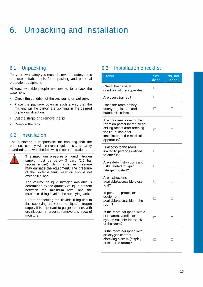
6.1 Unpacking
For your own safety you must observe the safety rulesand use suitable tools for unpacking and personalprotection equipment.
At least two able people are needed to unpack theassembly.
Check the condition of the packaging on delivery.
Place the package down in such a way that themarking on the carton are pointing in the desiredunpacking direction.
Cut the straps and remove the lid.
Remove the tank.
6.2 Installation
The customer is responsible for ensuring that thepremises comply with current regulations and safetystandards and with the following recommendations.
The maximum pressure of liquid nitrogensupply must be below 3 bars (1.5 barrecommended). Using a higher pressuremay damage the equipment. The pressureof the portable tank reservoir should notexceed 0.5 bar.
The volume of liquid nitrogen available isdetermined by the quantity of liquid presentbetween the minimum level and themaximum filling level in the supplying tank.
Before connecting the flexible filling line tothe supplying tank or the liquid nitrogensupply it is important to purge the lines withdry nitrogen in order to remove any trace ofmoisture.
6.3 Installation checklist
Action Yes,done
No, notdone
Check the generalcondition of the apparatus.
Are users trained?
Does the room satisfysafety regulations andstandards in force?
Are the dimensions of theroom (in particular the clearceiling height after openingthe lid) suitable forinstallation of the medicalapparatus?
Is access to the roomlimited to persons entitledto enter it?
Are safety instructions andrisks related to liquidnitrogen posted?
Are instructionsavailable/accessible closeto it?
Is personal protectionequipmentavailable/accessible in theroom?
Is the room equipped with apermanent ventilationsystem suitable for the sizeof the room?
Is the room equipped withan oxygen contentchecking system (displayoutside the room)?

16
Action Yes,done
No, notdone
Are safe distancesobserved (at least 0.5 maround the apparatus)?
Is the liquid nitrogen supplypressure lower than 3 bar?
Has the apparatus beingblown through (to eliminateall traces of humidity)?

7. Installing the components
This section describes the addition of the variousperipheral devices (dolly base, DL3 pump, foot pump,pouring handle, cart).
7.1 DL3 pump
The optional DL3 pump is fitted as follows:
Figure 7-1: the optional DL3 pump.
1. Screw on the bent part (1) at the star knob orquarter-turn valve (2), orienting it as illustrated.Note that it is possible:- to connect a hose directly in place of the bent
part. The valve does in fact have a standardtype 130 connection.
- to weld, on the bent outlet, an optional poralfilter.
2. Fit the seal (4) over the flange of the tank.
3. Insert the lower part of the pump partway (7-2, rep. 3) into the tank, taking care not to bangthe neck of the inner tank.The relief valve (Figure 7-2, rep. 1) shall beopened as a safety measure.
Note: the the tube (3) may need to be recut toadjust its overall height for the intended use.
Unscrew the top part of the pump (Figure2) to release the pipe to be immersed (rep. 3). Adjust its length so than it does not touchthe bottom of the tank before you tighten the upperpart (Figure 7-2, rep. 2).
Installing the components
This section describes the addition of the variousperipheral devices (dolly base, DL3 pump, foot pump,
The optional DL3 pump is fitted as follows:
Screw on the bent part (1) at the star knob orturn valve (2), orienting it as illustrated.
a hose directly in place of the bentpart. The valve does in fact have a standard
weld, on the bent outlet, an optional poral
Fit the seal (4) over the flange of the tank.
Insert the lower part of the pump partway (Figure, rep. 3) into the tank, taking care not to bang
rep. 1) shall be
Note: the the tube (3) may need to be recut toadjust its overall height for the intended use.
Figure 7-2, rep.2) to release the pipe to be immersed (Figure 7-2,rep. 3). Adjust its length so than it does not touch
you tighten the upper
Figure 7-2: DL3 pump, step 1.
4. Position the securing flange (and fasten it hand-tight.
5. Close the relief valve (Figure
6. You can connect a gradual pressurising systemwith a cylinder, or wait for the system to reach theright pressure by natural wastage.
Figure 7-3: DL3 pump, step 2.
17
Position the securing flange (Figure 7-3, rep. 2)
Figure 7-3, rep. 1).
You can connect a gradual pressurising systemlinder, or wait for the system to reach the
right pressure by natural wastage.

18
7.2 Foot pump
The optional foot pump is fitted as follows:
1. Connect up the components as shown.
1a.Screw the plastic end (rep. 3) onto the orificemarked INFL (rep. 3) on the pump.
1b.Next, join the other end of this plastic end piece(rep. 3) to the small bent pipe (rep. 1) on thestopper, using the transparent plastic pipe (rep.2).
Figure 7-4: foot pump, step 1.
2. Slide the stopper (1) to adjust thepipe (2) that will be inside the tank, depending onhow deep it is.
Figure 7-5: foot pump, step 2.
The optional foot pump is fitted as follows:
Connect up the components as shown.
Screw the plastic end (rep. 3) onto the orifice(rep. 3) on the pump.
of this plastic end piece(rep. 3) to the small bent pipe (rep. 1) on thestopper, using the transparent plastic pipe (rep.
Slide the stopper (1) to adjust the length of thepipe (2) that will be inside the tank, depending on
7.3 Pouring handle
7.3.1 Fitting the handle
Proceed as follows to ftank:
1. Unscrew the knurled handle.
2. Slide the pouring handle on, taking care not todamage the base of the tank.
Figure 7-6: pouring handle, step 1.
3. Position the pouring handle (2) so that the knurledhandle is on the same side as the pumping valve(1)
Figure 7-7: pouring handle, step 2.
4. Screw in the knurled handle untilmounted on the tank.
7.3.2 Removing the handle
Proceed as follows to remove the pouring handle fromthe tank:
1. Unscrew the knurled handle.
2. Slide the pouring handle down off the tank.
Pouring handle
Fitting the handle
Proceed as follows to fit the pouring handle onto the
Unscrew the knurled handle.
Slide the pouring handle on, taking care not todamage the base of the tank.
: pouring handle, step 1.
Position the pouring handle (2) so that the knurledhandle is on the same side as the pumping valve
: pouring handle, step 2.
Screw in the knurled handle until it is firmlymounted on the tank.
Removing the handle
Proceed as follows to remove the pouring handle from
Unscrew the knurled handle.
Slide the pouring handle down off the tank.

19
Figure 7-8: removing the pouring handle.
7.4 Tipping cart
To mount the tank on the cart, proceed as follows.
1. Position the empty tank in the ring, with thepumping valve (1) pointing upwards.Warning: there are 2 different types of tilting cart tosuit different types of storage tank (see section5.2.4, on page 14).
2. Tighten the screw (rep. 2) and check that it issecure.
Figure 7-9: tipping cart.

20

21
8. Use
This section describes the use of the assembled tankduring transport, handling, filling (by gravity or from atype TP supply tank) and withdrawal (using the liquidnitrogen).
8.1 Storage precautions
Before installing the equipment or using it forthe first time, it is essential to refer to thesafety instructions on page 7.
The storage tank must always be keptsheltered from exposure to the elements,with its control head or stopper fitted.
8.2 Moving
Tanks can be full or empty when movedoverland, provided that they are open toatmosphere, i.e. with the stopper fitted.
Never seal a tank; use the stopperprovided.
The pressure inside the tank must be atmosphericpressure. This is simply achieved by inserting thestopper provided so as to restrict loss of nitrogen andprevent the entry of moisture. The insulating stopperprovided improves the rate of evaporation of the liquidnitrogen by 35%.
8.3 Handling
The TR line of products has been designed towithstand the impacts that are unavoidable when atank is moved. Nevertheless, to minimise the rate ofloss and maximise the service life of tanks, westrongly recommend that you:
Avoid severe impacts.
Keep tanks upright at all times.
Only move a tank inside the same laboratory (donot use the tank as an intensive transport tank).
If possible, use the optional dolly base.
8.4 Filling the tank
The tank can be filled by one of the followingmethods:
By gravity, pouring the liquefied gas as one wouldfrom a bottle.
From a refill tank (a TP tank, line, etc.) using theright hose for that refill tank.
For any operation with a liquefied gas youmust wear protective gloves and goggles.Mandatory: Protect your hands usingappropriate personal protection equipment.
The gas transferred is at a very lowtemperature.
When filling, ensure that no personnelor equipment is near the place oftransfer.
8.4.1 Refilling from a refill tank
Refer to the TP tank manual.
8.4.2 Filling from a TR tank
This filling operation shall be carried out with orwithout a cart, depending on the size of the refill tank.The procedure consists in transferring the liquidnitrogen by gravity (pouring from one tank intoanother). It can only be done with tanks that are nottoo heavy for the operator.
Refer to the safety notes in section 8.4, inpage 21.
The tank must never be left unattendedduring the filling stage.
1. Remove the stopper.
2. Hold the tank as shown.

22
Figure 8-1: filling from a TR vessel; step 1.
3. Pour the liquid nitrogen into the tank up to thedesired level. The highest permitted level of liquidis the lower edge of the neck. The quantity of liquidnitrogen introduced can be checked by weighing,given that 1 litre of liquid nitrogen has a mass ofapproximately 0.808 kg at atmospheric pressure.Please refer to the table in section29for the weights.
Make sure not to overfill the tank duringmanual filling so as to avoid rupturing thevacuum in the inner wall (liquid nitrogencoming in contact with the pump check valve1).
Figure 8-2: filling from a TR vessel; warning.
8.4.3 Filling with an installed DL3 pump
1. Check that the star knob or quarterclosed, just like the relief valve.
2. Unscrew the nut (2) and remove the bent part (1)
3. Connect a flexible line from the supply tank to theend piece (3).
Pour the liquid nitrogen into the tank up to thedesired level. The highest permitted level of liquidis the lower edge of the neck. The quantity of liquidnitrogen introduced can be checked by weighing,
itrogen has a mass ofapproximately 0.808 kg at atmospheric pressure.Please refer to the table in section 10.1 on page
Make sure not to overfill the tank duringmanual filling so as to avoid rupturing thevacuum in the inner wall (liquid nitrogencoming in contact with the pump check valve -
Filling with an installed DL3 pump
Check that the star knob or quarter-turn valve (4) is
screw the nut (2) and remove the bent part (1)
Connect a flexible line from the supply tank to the
Figure 8-3:filling with a DL3 pump in place; step 1.
4. Open the relief valve (5) (
5. Open the star knob (
6. Filling is completed when liquid comes out of theend (Figure 8-4, rep.
7. Close the star knob (relief valve (Figure 8
Figure 8-4: filling with a DL3 pump in place; step 2.
Take caution to avoid being burned bycryogenic liquid coming out through therelief valve's tip
If a pressure of 0.3 barduring filling the tank can be usedimmediately. If it has not, wait for the tankpressure to rise.
:filling with a DL3 pump in place; step 1.
Open the relief valve (5) (Figure 8-4, rep. 5).
Open the star knob (Figure 8-3, rep. 4).
is completed when liquid comes out of the, rep. 7) of the relief valve.
Close the star knob (Figure 8-3, rep.4) and the8-4, rep. 5).
: filling with a DL3 pump in place; step 2.
Take caution to avoid being burned bycryogenic liquid coming out through therelief valve's tip (rep. 7).
If a pressure of 0.3 bar is maintainedduring filling the tank can be usedimmediately. If it has not, wait for the tankpressure to rise.

8.5 Drawing off
Drawing off consists in transferring the liquid nitrogenfrom the tank to another container. It is carried outusing specially designed draw off equipment(simplified draw off apparatus, a foot pumpdevice) fitted to the neck of the tank.
8.5.1 Safety
Nitrogen should be handled in a suitablyroom, preferably with an oxygen level detectorinstalled. Indeed, nitrogen is neitherflammable, but may cause oxygen depletion inconfined spaces.
The manual draw off pipe is provided only for fillingsmall capacity containers. During the various draw offoperations, cryogenic gloves or protective glassesmust be used.
8.5.2 Draw off using the simplifiedapparatus
8.5.2.1 Setting up1. Unscrew the black handle (1) to release the
reflector (2). Lift up the rubber plug (3).
2. Gently lower the pipe (8) down to the bottom of thepreferably empty tank.If the tank is full, there is a risk of nitrogensplashes. The pipe outlet should be turned towardsa safe area before handling.
3. Raise the pipe by 2 to 3 cm, then adjust the plug(6) to the height of the neck (7).
4. Lower the reflector (5) then re-tighten the blackhandle (4).
Figure 8-5: setting up stages for drawing off.
8.5.2.2 Procedure1. Lower the draw off pipe whilst holding the
container to be filled (1) up to the pipe outlethold the pipe using the handle (2) without pressinghard. Filling is instantaneous.
the liquid nitrogenIt is carried out
using specially designed draw off equipmentfoot pump or DL3
suitably ventilatedroom, preferably with an oxygen level detector
Indeed, nitrogen is neither toxic norflammable, but may cause oxygen depletion in
The manual draw off pipe is provided only for fillingDuring the various draw off
operations, cryogenic gloves or protective glasses
Draw off using the simplified
Unscrew the black handle (1) to release the
down to the bottom of the
there is a risk of nitrogenThe pipe outlet should be turned towards
then adjust the plug
tighten the black
Lower the draw off pipe whilst holding theup to the pipe outlet and
without pressing
2. To stop the draw off, remove the pipecontainer (1).The draw off takes place because of heat from thepipe entering the container
3. For repeated filling operationswarm up for a few minutes to reach externaltemperature.
Figure 8-6: drawing off.
8.5.3 With the foot pump
Proceed as follows:
Refer to the safety notes in sectionin page 21.
The tank must never be left unattendedduring the withdrawal stage.
1. Before starting, blow dry air or nitrogen through thelines and the valves to remove any moisture.
2. Fit the foot pump as shown in section18.
3. Fit the foot pump onto the neck of the
4. Place the anti-splash devicetank.
5. Pump with the foot until the liquid reaches themaximum level in the receiving tank.
23
remove the pipe (2) from the
The draw off takes place because of heat from the
For repeated filling operations, allow the pipe towarm up for a few minutes to reach external
With the foot pump
Refer to the safety notes in section 8.4,
The tank must never be left unattendedduring the withdrawal stage.
starting, blow dry air or nitrogen through thelines and the valves to remove any moisture.
Fit the foot pump as shown in section 7.2, in page
Fit the foot pump onto the neck of the TR tank.
splash device (1) into the receiving
foot until the liquid reaches themaximum level in the receiving tank.

24
Figure 8-7: transferring with the foot pump.
8.5.4 With the DL3 pump
Positioning the DL3 pump
Refer to the safety notes in section 8.4,in page 21.
The tank must never be left unattendedduring the withdrawal stage.
1. Before starting, blow dry air or nitrogen through thelines and the valves to remove any moisture.
2. Fit the pump as shown in section 7.1, in page 17.
3. Check that the relief valve (4) and the liquidwithdrawal valve (3) are closed.
Beware of possible splashes of nitrogen.
Figure 8-8: transferring with the DL3 pump.
4. Close the relief valve (4) again.
5. Connect either the bent pipe (1) or a suitableflexible line to the 130 mm nut (2).
Using the DL3 pump
It is important to note that the tank becomespressurised by natural losses. Consequently thelength of time it takes before it is available for use willvary.
Note: In order to be able to use the deviceimmediately the connection on the relief valve (6) canbe used (no. 7 in figure on previous page) to connecta tube via which the tank can be rapidly pressurisedfrom, for example, a small bottle of nitrogen gas.
Proceed as follows:
1. Open the liquid withdrawal valve (Figure 8-9, rep.1). Check that the pressure is lower than 0.5 bar(Figure 8-9, rep. 2).
Figure 8-9: using the DL3 pump.
2. Once liquid is coming out, the withdrawal valve(Figure 8-9, rep. 1). can be opened more fully
3. Close the withdrawal valve (Figure 8-9, rep. 1) tostop more nitrogen from coming out.
Note: if a nitrogen gas cylinder is connected (4),adjust the valve (3) too in order to control the flowof liquid nitrogen.
Removing the DL3 pump
Refer to the safety notes in section 8.4,in page 21.
Figure 8-10: removing the DL3 pump.
1. Disconnect the pressurisation pipe (4), if used,from the relief valve (3)
2. Check that the withdrawal valve (1) is properlyclosed.
34
2
1

25
3. Open the relief valve (rep. 3).
4. Wait until gas is no longer flowing at theconnection (4) of this valve before going on to thenext step.
5. Remove the clamping ring (rep. 5).
6. Remove the pump from the tank.
7. Dry the pump all over before storing it where it willnot suffer any impacts.

26

27
9. Maintenance
This section summarizes the procedures forinspecting and changing the components of thecontrol head. It also describes calibration of thepressure gauge.
9.1 Preventive maintenance
This section is for skilled and qualified persons whoare authorized to carry out maintenance work.Maintenance is necessary to ensure that theequipment remains in normal operating condition. Theperson who uses the equipment is responsible forthis. The tools used for maintenance operations mustbe non-abrasive and should have no sharp edges orpoints that could damage the surfaces.
Operation Frequency
Cleaning the outside of the tank
Important note: cleaning is limitedto the outer parts of the device. Theuse of acetone, solvents or anyother highly flammable chemicalsor liquid-containing chlorineproducts is prohibited.
Wipe the plastic parts with a dry ragand, if necessary, with a slightlymoist non-abrasive sponge (do notuse abrasive powder) or withimpregnated wipes.
Ordinary domestic cleaningproducts (slightly abrasive creamscontaining ammonia) applied with asponge will be acceptable for thetank and the stainless steel parts.Afterwards, rinse with a damp rag,then wipe and leave to dry.
Every 5weeks (*)
Airtight seal Every year
Safety valve Every year
(*)The frequencies shown are guideline intervals and should be adjusted bythe user according to the use made of the equipment.
9.2 Replacing the centring ringseal
This is necessary if leaks are detected here. Changethe ring and seal assembly.

28

29
10. Technical specifications
10.1 Tank
Unity TR7 TR11 TR21 TR26 TR35 TR60 TR100
Total capacity Litres 7 12 21 26 33 60 99
Working capacity Litres 7,2 12,2 21,5 26 33,6 60 99
Diameter of neck mm 50 50 50 50 50 50 50
Weight when empty kg 6 7,5 11 13,5 15,8 21,5 29,5
Weight when full of nitrogen kg 11,8 17,3 28,3 34,6 43 70 110
External diameter (D) mm 308 308 388 388 468 468 510
Overall height (H) mm 480 584 605 669 655 869 986
Evaporation per day (1) Litre/day 0,2 0,18 0,18 0,2 0,24 0,4 0,55
Static duration of use Day 36 67 119 130 140 150 180
Total internal height mm 405 530 535 612 580 800 933
Handles(A) or (P) A A P P P P P
Working temperature °C 20 20 20 20 20 20 20
Storage temperature °C <50 <50 <50 <50 <50 <50 <50
(1) Daily evaporation and static duration of use are given for 20 °C, 1013 mbars, with the tank stationary and the stopper closed. These are nominal values and mayvary depending on the history of the tank and manufacturing tolerances.
Figure 10-1: dimensional characteristics (dimensions in mm).

30
10.2 DL3 pump
Feature Principal characteristics
Height 1 m.
Nitrogen pressure Pressure gauge (graduation from 0 to 1 bar).
Installation Flange.
Valves Filling / withdrawal.
Vent / overflow.

31
11. Spare parts
11.1 Storage tank
Item Code
Stopper ACC-TR-14
11.2 DL3 pump
Item Code
DL3 pump, complete ACC-TR-5
Pressure gauge ACC-TR-19
Safety valve ACC-TR-8
Seal for centring ring ACC-ALU-16
Centring ring, complete (with seal) ACC-ALU-14
Liquid withdrawal valve, nom. dia. 12 mm ACC-TR-6
Membrane and shutter assembly for liquid withdrawal valve, nom. dia. 12 mm ACC-TR-7
Clamping ring ACC-ALU-15
Complete control head (pressure gauge, clamping ring, seal, centring ring, valve,relief valve)
ACC-TR-11
Control head nut ACC-TR-12
Gland packing ACC-TR-13
Relief valve ACC-TR-21
Withdrawal tube ACC-TR-23
Bent tube ACC-TR-24

32
11.3 Foot pump
Item Code
Foot pump, complete ACC-TR-1
11.4 Accessories
Item Code
Elbow with anti-splash device ACC-TP-17
Anti-splash device ACC-ALU-12
Adjustable dolly base
Standard adjustable dolly base for TR21/TR26/TR35/TR60/TR100 ACC-ALU-29
Non-magnetic adjustable dolly base for TR35/TR60/TR100 ACC-ALU-31
Lock kit (3 units) ACC-ALU-32
Item ACC-TR-14
Insulating stoppers
Insulating stopper for TR 7/11/21/26/35/60/100 ACC-TR-17
Cart ACC-TR-18
Cart for TR21 and TR26
Cart for TR35 ACC-TR-16
Pouring handle ACC-TR-15
Pouring handle for TR21 and TR26
Pouring handle for TR35 ACC-FL180TCNL-08
Hoses ACC-FL180TCNL-15
180TC hose for nitrogen, nom. dia. 10 mm, 800 mm long ACC-FL630TCNL-15
180TC hose for nitrogen, nom. dia. 10 mm, 1500 mm long ACC-FL630TCNL-20
630TC hose for nitrogen, nom. dia. 16 mm, 1500 mm long ACC-FL630TCNL-15
630TC Flexible line for nitrogen, nom. dia. 16 mm, 2000 mm long ACC-FL630TCNL-20

33
12. Warranty and limit of liability
12.1 Warranty
The warranty period takes effect on the date of issueof the equipment delivery note and has a duration ofone year.
Goods are delivered at the vendor’s risk if deliveredby a carrier appointed by Cryopal. In other casesdelivery is at the buyer’s risk.
The vendor guarantees the equipment against alldesign faults and defects of manufacture andconstruction affecting the storage tanks.
The seller's guarantee is strictly limited, at the seller'sdiscretion, to repairing or replacing the parts which itacknowledges as defective and to its labour expensesother than transport and packing charges.
Replaced defective parts become the property of thevendor.
The repair, modification or replacement of parts duringthe guarantee period does not extend the duration ofthe guarantee.
To qualify for the guarantee, the user must submit aclaim to the vendor within 15 days of its receipt of theequipment, accompanied by the delivery note.
The required repairs, modifications or replacementsdue to normal wear and tear, deteriorations oraccidents from faulty operation, insufficientsupervision or maintenance, negligence, overloads, ause not conforming to the utilization regulations, aswell as shocks, drops, or degradations due to badweather are not covered by the guarantee (see theoperating instructions).
This guarantee is immediately invalidated in the eventof the replacement or repair of original parts bypersons not duly authorized by Cryopal.
Within the limits imposed by applicable legislation, it isexpressly agreed that the guarantee awarded in thisarticle is the only guarantee implicitly, explicitly orlawfully granted by the vendor with regard to thematerials sold, and that, except where stated to thecontrary in writing, the buyer renounces entitlement toany legal action which the buyer (or its employees,affiliate companies, successors or concessionholders) might take against the vendor, its employees,
affiliate companies, successors or concessionholders, in connection with the materials sold; thisprovision includes without limitation actionsconcerning personal injury, damage to goods notcovered by the agreement, indirect or immateriallosses or damage and particularly loss of use or ofprofit, loss of cryogenic liquid or of products in storageetc. Within the limits imposed by applicable legislation,the buyer undertakes to compensate the vendor, itsemployees, affiliate companies, successors andconcession holders, for all claims, complaints,demands, court orders, convictions or liabilities of anynature, as well as all costs and expenses incurred byor imposed on the vendor in connection with thematerials sold.
Replacement parts must be used in the conditions ofservice originally defined by the vendor. In particular,safety devices sold as replacement parts must beinstalled as replacements for the original safetydevices in conditions of service (pressure,temperature, gas, valve diameter etc.) identical to theoriginal</cf>
Application of this guarantee takes place inaccordance with the vendor’s general terms andconditions of sale.
12.2 Limit of liability
Neither Cryopal, nor any related company, may underany circumstances be held liable for any damages,included but not limited to damages for loss ofmanufacture, interruption of manufacture, loss ofinformation, defect in the indicator or its accessories,bodily harm, loss of time, financial or material losses,or for any consequences whether indirect orsubsequent to a failure occurring in the course of use,or inability to use the product, even in a situationwhere Cryopal had been made aware of suchdamages.

34

35
13. Index
A
Accessories, 32Dolly base, 32Hose, 32Insulating stopper, 32Pouring handles, 32Tilting cart, 32
Airtight sealReplacement, 27
Anti-splash device, 23
C
Centring ringReplacement, 27
Cleaning, 27Components, 11Components supplied, 9Composants, 11Copyright, 2
D
Description, 13Destruction, 8DL3, 14
Installation, 17Positioning, 24Removal, 24Spare parts, 31Specifications, 30Use, 24
DL3 pumpInstallation, 17Positioning, 24Spare parts, 31Specifications, 30
DL3:External nitrogen cylinder,14
DL3:Manual valve, 14DL3:Pressure control, 14DL3:Pressure intake, 14DL3:Relief outlet., 14DN50, 13Dolly base
Accessories, 32
Foot brake, 14Overview, 14
E
EIS, 8E-mail, 2Equipment
Destruction, 8
F
Fault, 8Foot brake, 14Foot pump
Installation, 18Positioning:, 23Spare parts, 32Use, 23
Function, 11
G
General, 11General safety, 7
H
Handle, 13Head flange, 13Hose
Accessories, 32http, 2
I
INFL, 18Inner wall, 13Installation, 15
Checklist, 15Installing the components, 17
L
Limit of liability, 33
M
Maintenance, 27
Manual, 5, 9Purpose, 5Readership, 5Skimming, 5Structure, 5Use, 5
Moving, 21
O
OverviewDL3 pump, 14Dolly base, 14Foot pump, 13Pouring handle, 14Tank, 13Tilting cart, 14
P
Page Web, 2Pompe à pied
INFL, 18Positioning
Foot pump, 23Positioning the DL3 pump, 24Pouring handle, 14, 32
Disassembly, 18Fitting, 18
Pump check valve, 18, 19, 22
R
RécipientSoutirage, 23Utilisation, 23
RemovalDL3 pump, 24
S
Safety, 7Liquid nitrogen, 8Operators, 7
Site web Cryopal, 2Skimming, 5Soutirage
Avec dispositif simplifié, 23

36
Mode opératoire, 23Sécurité, 23
Spare partsDL3 pump, 31Foot pump, 32
SpecificationsDL3 pump, 30
StopperAccessories, 32
Stopper:Insulating, 13Stopper:Stopping, 13Storage
Tank, 21Structure of the manual, 5
T
Tank, 13Cleaning, 27Filling, 21Handling, 21Maintenance, 27Moving, 21Storage, 21
Tilting cart, 14Accessories, 32Description, 14
Tipping cartFitting, 19
Trade names cited, 5
U
Unpacking, 15Use, 21
DL3 pump, 24Foot pump, 23
W
Warranty, 33Web, 2Withdrawal system
DL3 – overall view, 14Foot pump – overall view, 13
www, 2

37

38