pressure vessels
TRANSCRIPT

Contents
1 Notations 2
2 Classification of Pressure Vessels 3
3 Stresses in a Thin Cylindrical Shell due to an Internal Pressure 3
4 Circumferential or Hoop Stress 4
5 Longitudinal Stress 5
6 Change in Dimensions of a Thin Cylindrical Shell due to an Internal Pressure 5
7 Thin Spherical Shells Subjected to an Internal Pressure 57.1 Diameter of the shell design . . . . . . . . . . . . . . . . . . . . . . . . . . . . . . . . . . . . . . . . . . . . . . . . . . 57.2 Thickness of the shell design . . . . . . . . . . . . . . . . . . . . . . . . . . . . . . . . . . . . . . . . . . . . . . . . . . 5
8 Change in Dimensions of a Thin Spherical Shell due to an Internal Pressure 6
9 Thick Cylindrical Shells Subjected to an Internal Pressure 6
10 Compound Cylindrical Shells 8
11 Stresses in Compound Cylindrical Shells 811.1 Stresses at the inner surface of the inner cylinder . . . . . . . . . . . . . . . . . . . . . . . . . . . . . . . . . . . . . . 911.2 Stresses at the outer surface of the inner cylinder . . . . . . . . . . . . . . . . . . . . . . . . . . . . . . . . . . . . . . 911.3 Stresses at the inner surface of the outer cylinder . . . . . . . . . . . . . . . . . . . . . . . . . . . . . . . . . . . . . . 1011.4 Stresses at the outer surface of the outer cylinder . . . . . . . . . . . . . . . . . . . . . . . . . . . . . . . . . . . . . . 1011.5 Cylinder deformation . . . . . . . . . . . . . . . . . . . . . . . . . . . . . . . . . . . . . . . . . . . . . . . . . . . . . . 1011.6 Tangential stress at the inner surface of the inner cylinder with internal pressure (pi) . . . . . . . . . . . . . . . . . . 1111.7 Tangential stress at the outer surface of the inner cylinder or inner surface of the outer cylinder with internal pressure
(pi) . . . . . . . . . . . . . . . . . . . . . . . . . . . . . . . . . . . . . . . . . . . . . . . . . . . . . . . . . . . . . . . . 1111.8 Tangential stress at the outer surface of the outer cylinder with internal pressure (pi) . . . . . . . . . . . . . . . . . . 1111.9 Resultant stress at the inner surface . . . . . . . . . . . . . . . . . . . . . . . . . . . . . . . . . . . . . . . . . . . . . 1111.10Resultant stress at the outer surface of the inner cylinder . . . . . . . . . . . . . . . . . . . . . . . . . . . . . . . . . 1111.11Resultant stress at the inner surface of the outer cylinder . . . . . . . . . . . . . . . . . . . . . . . . . . . . . . . . . 1111.12Total resultant stress at the mating or contact surface . . . . . . . . . . . . . . . . . . . . . . . . . . . . . . . . . . . 1111.13Resultant stress at the outer surface of the outer cylinder . . . . . . . . . . . . . . . . . . . . . . . . . . . . . . . . . 11
12 Cylinder Heads and Cover Plates 11
13 Examples 14
14 References 28
15 Contacts 28
1 Notations
• p = Intensity of internal pressure (gage pressure).
• d = Internal diameter of the cylindrical shell.
• l = Length of the cylindrical shell.
• t = Thickness of the cylindrical shell.
• σt1 = Circumferential or hoop stress for the material of the cylindrical shell.
• ηl = Efficiency of the longitudinal riveted joint.
• σt2 = Longitudinal stress.
• E = Youngs modulus for the material of the cylindrical shell.
• µ = Poissons ratio.
• V = Storage capacity of the shell.
• σt = Permissible tensile stress for the shell material (or Tangential stress for thick cylindrical shell.).
• ro = Outer radius of cylindrical shell.
• ri = Inner radius of cylindrical shell.
• σr = Radial stress.
• σu = Ultimate stress.
• po = External pressure.
• pi = Internal pressure.
• Eo = Young’s modulus for the material of the outer cylinder.
• Ei = Young’s modulus for the material of the inner cylinder.
• δo = Increase in outer radius of the inner cylinder.
• δi = Decrease in outer radius of the inner cylinder.
• δr = Difference in radius.
• εto = Tangential strain in the outer cylinder at the inner radius (r2).
• R = Inside radius of curvature of the plate.
• c = Camber or radius of the dished plate.

2 Classification of Pressure Vessels
The pressure vessels may be classified as follows:
1. According to the dimensions.The pressure vessels, according to their dimensions, may be classified as thin shell or thick shell. If thewall thickness of the shell (t) is less than 1/10 of the diameter of the shell (d), then it is called a thin shell.On the other hand, if the wall thickness of the shell is greater than 1/10 of the diameter of the shell, thenit is said to be a thick shell. Thin shells are used in boilers, tanks and pipes, whereas thick shells areused in high pressure cylinders, tanks, gun barrels etc.Note: Another criterion to classify the pressure vessels as thin shell or thick shell is the internal fluidpressure (p) and the allowable stress (σt). If the internal fluid pressure (p) is less than 1/6 of the allowablestress, then it is called a thin shell. On the other hand, if the internal fluid pressure is greater than 1/6of the allowable stress, then it is said to be a thick shell.
2. According to the end construction.The pressure vessels, according to the end construction, may be classified as open end or closed end.A simple cylinder with a piston, such as cylinder of a press is an example of an open end vessel, whereas atank is an example of a closed end vessel. In case of vessels having open ends, the circumferential or hoopstresses are induced by the fluid pressure, whereas in case of closed ends, longitudinal stresses in additionto circumferential stresses are induced.
3 Stresses in a Thin Cylindrical Shell due to an Internal Pressure
The analysis of stresses induced in a thin cylindrical shell are made on the following assumptions:
1. The effect of curvature of the cylinder wall is neglected.
2. The tensile stresses are uniformly distributed over the section of the walls.
3. The effect of the restraining action of the heads at the end of the pressure vessel is neglected.
When a thin cylindrical shell is subjected to an internal pressure, it is likely to fail in the following two ways:
1. It may fail along the longitudinal section (i.e. circumferentially) splitting the cylinder into two troughs.
2. It may fail across the transverse section (i.e. longitudinally) splitting the cylinder into two cylindricalshells.
Thus the wall of a cylindrical shell subjected to an internal pressure has to withstand tensile stresses of thefollowing two types:
1. Circumferential or hoop stress, and
2. Longitudinal stress.
Figure 1: Failure of a cylindrical shell.
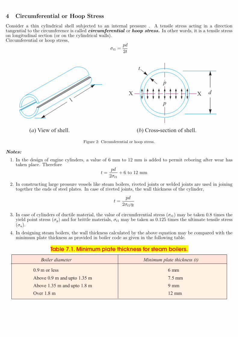
4 Circumferential or Hoop Stress
Consider a thin cylindrical shell subjected to an internal pressure . A tensile stress acting in a directiontangential to the circumference is called circumferential or hoop stress. In other words, it is a tensile stresson longitudinal section (or on the cylindrical walls).Circumferential or hoop stress,
σt1 =pd
2t
Figure 2: Circumferential or hoop stress.
Notes:
1. In the design of engine cylinders, a value of 6 mm to 12 mm is added to permit reboring after wear hastaken place. Therefore
t =pd
2σt1+ 6 to 12 mm
2. In constructing large pressure vessels like steam boilers, riveted joints or welded joints are used in joiningtogether the ends of steel plates. In case of riveted joints, the wall thickness of the cylinder,
t =pd
2σt1ηl
3. In case of cylinders of ductile material, the value of circumferential stress (σt1) may be taken 0.8 times theyield point stress (σy) and for brittle materials, σt1 may be taken as 0.125 times the ultimate tensile stress(σu).
4. In designing steam boilers, the wall thickness calculated by the above equation may be compared with theminimum plate thickness as provided in boiler code as given in the following table.
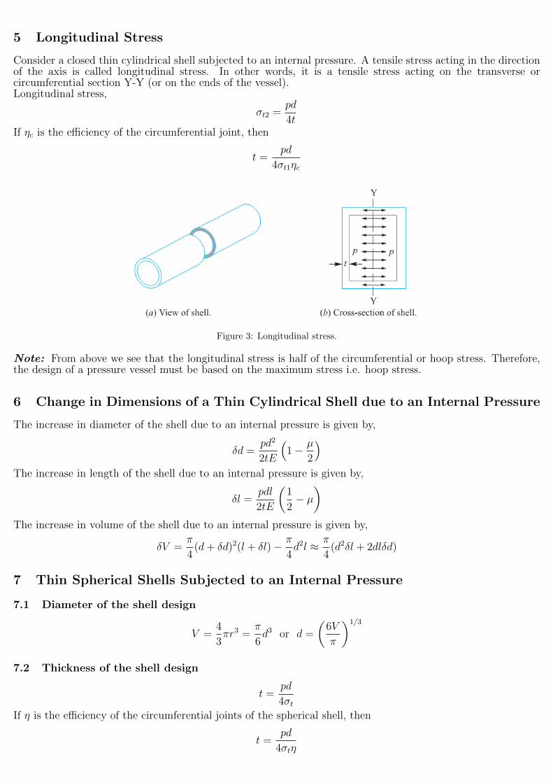
5 Longitudinal Stress
Consider a closed thin cylindrical shell subjected to an internal pressure. A tensile stress acting in the directionof the axis is called longitudinal stress. In other words, it is a tensile stress acting on the transverse orcircumferential section Y-Y (or on the ends of the vessel).Longitudinal stress,
σt2 =pd
4tIf ηc is the efficiency of the circumferential joint, then
t =pd
4σt1ηc
Figure 3: Longitudinal stress.
Note: From above we see that the longitudinal stress is half of the circumferential or hoop stress. Therefore,the design of a pressure vessel must be based on the maximum stress i.e. hoop stress.
6 Change in Dimensions of a Thin Cylindrical Shell due to an Internal Pressure
The increase in diameter of the shell due to an internal pressure is given by,
δd =pd2
2tE
(1− µ
2
)The increase in length of the shell due to an internal pressure is given by,
δl =pdl
2tE
(1
2− µ
)The increase in volume of the shell due to an internal pressure is given by,
δV =π
4(d+ δd)2(l + δl)− π
4d2l ≈ π
4(d2δl + 2dlδd)
7 Thin Spherical Shells Subjected to an Internal Pressure
7.1 Diameter of the shell design
V =4
3πr3 =
π
6d3 or d =
(6V
π
)1/3
7.2 Thickness of the shell design
t =pd
4σtIf η is the efficiency of the circumferential joints of the spherical shell, then
t =pd
4σtη
8 Change in Dimensions of a Thin Spherical Shell due to an Internal Pressure
The increase in diameter of the spherical shell due to an internal pressure is given by,
δd =pd2
4tE(1− µ)
The increase in volume of the spherical shell due to an internal pressure is given by,
δV =π
6(d+ δd)3 − π
6d3 ≈ π
6(3d2δd) =
πpd4
8tE(1− µ)
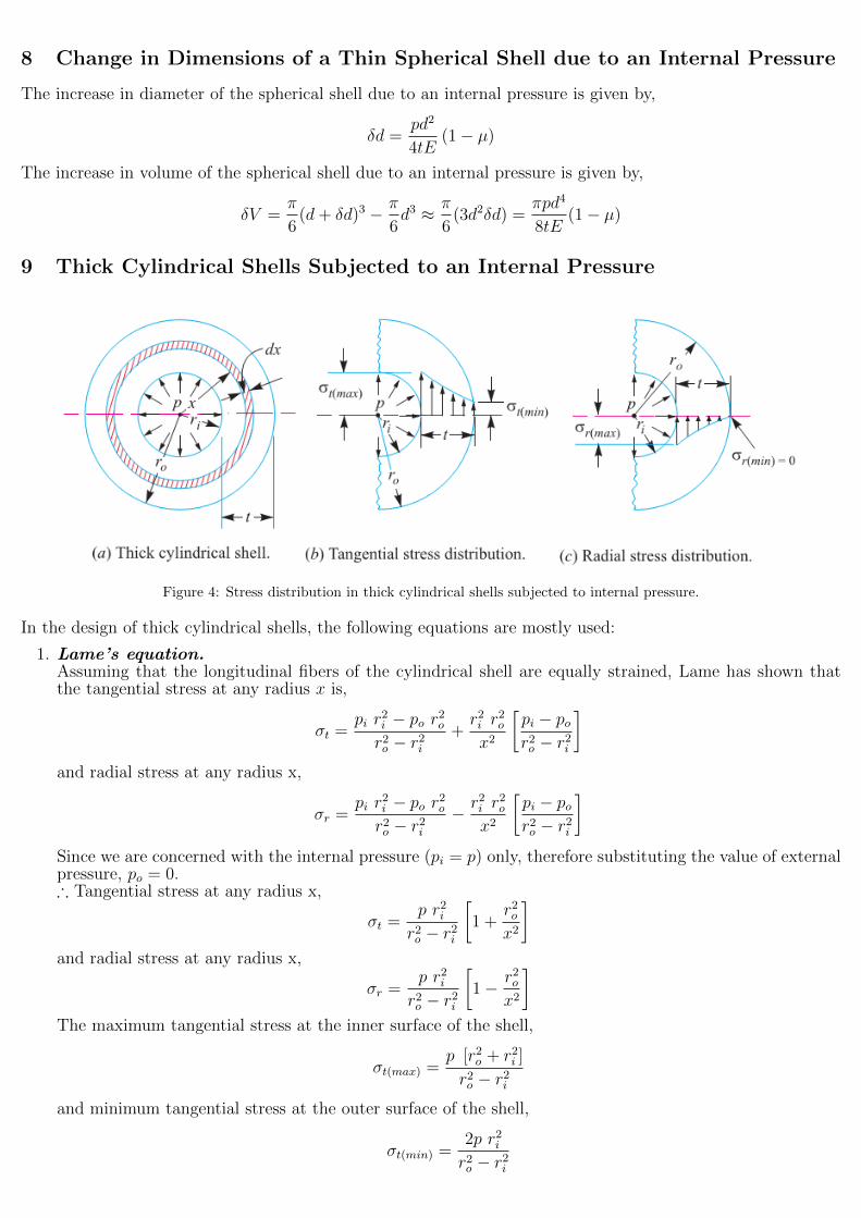
9 Thick Cylindrical Shells Subjected to an Internal Pressure
Figure 4: Stress distribution in thick cylindrical shells subjected to internal pressure.
In the design of thick cylindrical shells, the following equations are mostly used:
1. Lame’s equation.Assuming that the longitudinal fibers of the cylindrical shell are equally strained, Lame has shown thatthe tangential stress at any radius x is,
σt =pi r
2i − po r2or2o − r2i
+r2i r
2o
x2
[pi − por2o − r2i
]and radial stress at any radius x,
σr =pi r
2i − po r2or2o − r2i
− r2i r2o
x2
[pi − por2o − r2i
]Since we are concerned with the internal pressure (pi = p) only, therefore substituting the value of externalpressure, po = 0.∴ Tangential stress at any radius x,
σt =p r2ir2o − r2i
[1 +
r2ox2
]and radial stress at any radius x,
σr =p r2ir2o − r2i
[1− r2o
x2
]The maximum tangential stress at the inner surface of the shell,
σt(max) =p [r2o + r2i ]
r2o − r2iand minimum tangential stress at the outer surface of the shell,
σt(min) =2p r2ir2o − r2i
The maximum radial stress at the inner surface of the shell,
σr(max) = −p (compressive)
and minimum radial stress at the outer surface of the shell,
σr(min) = 0
In designing a thick cylindrical shell of brittle material (e.g. cast iron, hard steel and cast aluminium)with closed or open ends and in accordance with the maximum normal stress theory failure, the tangentialstress induced in the cylinder wall,
σt = σt(max) =p [r2o + r2i ]
r2o − r2i∵ ro = ri + t
∴ t = ri
[√σt + p
σt − p− 1
]The value of σt for brittle materials may be taken as 0.125 times the ultimate tensile strength (σu).We have discussed above the design of a thick cylindrical shell of brittle materials. In case of cylindersmade of ductile material, Lame’s equation is modified according to maximum shear stress theory.According to this theory, the maximum shear stress at any point in a strained body is equal to one-halfthe algebraic difference of the maximum and minimum principal stresses at that point. We know that fora thick cylindrical shell,
σt(max) =p [r2o + r2i ]
r2o − r2iand minimum principal stress at the outer surface,
σr(max) = −p∴ Maximum shear stress,
τ = τmax =σt(max) − σt(min)
2=
p [r2o+r2i ]r2o−r2i
+ p
2=
p r2o2 [r2o − r2i ]
∵ ro = ri + t
∴ t = ri
[√τ
τ − p− 1
]The value of shear stress (τ) is usually taken as one-half the tensile stress (σt). Therefore the aboveexpression may be written as
t = ri
[√σt
σt − 2p− 1
]From the above expression, we see that if the internal pressure (p) is equal to or greater than the allowableworking stress (σt or τ), then no thickness of the cylinder wall will prevent failure. Thus, it is impossible todesign a cylinder to withstand fluid pressure greater than the allowable working stress for a given material.
2. Birnie’s equation.In case of open-end cylinders (such as pump cylinders, rams, gun barrels etc.) made of ductile material(i.e. low carbon steel, brass, bronze, and aluminum alloys), the allowable stresses cannot be determined bymeans of maximum-stress theory of failure. In such cases, the maximum-strain theory is used. Accordingto this theory, the failure occurs when the strain reaches a limiting value and Birnie’s equation for the wallthickness of a cylinder is
t = ri
[√σt + (1− µ)p
σt − (1 + µ)p− 1
]The value of σt may be taken as 0.8 times the yield point stress (σy).
3. Clavarino’s equation.This equation is also based on the maximum-strain theory of failure, but it is applied to closed-end cylinders(or cylinders fitted with heads) made of ductile material. According to this equation, the thickness of acylinder,
t = ri
[√σt + (1− 2µ)p
σt − (1 + µ)p− 1
]

4. Barlows equation.This equation is generally used for high pressure oil and gas pipes. According to this equation, the thicknessof a cylinder,
t =proσt
For ductile materials, σt = 0.8σy and for brittle materials σt = 0.125σu.
Note: The use of these equations depends upon the type of material used and the end construction.
10 Compound Cylindrical Shells
According to Lame’s equation, the thickness of a cylin-drical shell is given by
t = ri
[√σt + p
σt − p− 1
]From this equation, we see that if the internal pres-sure (p) acting on the shell is equal to or greater thanthe allowable working stress (σt) for the material of theshell, then no thickness of the shell will prevent failure.Thus it is impossible to design a cylinder to withstandinternal pressure equal to or greater than the allowableworking stress.This difficulty is overcome by inducing an initial com-pressive stress on the wall of the cylindrical shell. Thismay be done by the following two methods:
1. By using compound cylindrical shells, and
2. By using the theory of plasticity. Figure 5: Compound cylindrical shell.
11 Stresses in Compound Cylindrical Shells
The stresses resulting from this pressure may be easily determined by using Lame’s equation. The tangentialstress at any radius x is
σt =pi r
2i − po r2or2o − r2i
+r2i r
2o
x2
[pi − por2o − r2i
]and radial stress at any radius x,
σr =pi r
2i − po r2or2o − r2i
− r2i r2o
x2
[pi − por2o − r2i
]If pi = 0:
σt =−po r2or2o − r2i
[1 +
r2ix2
]σr =
−po r2or2o − r2i
[1− r2i
x2
]If p0 = 0:
σt =pi r
2i
r2o − r2i
[1 +
r2ox2
]σr =
pi r2i
r2o − r2i
[1− r2o
x2
]

Figure 6: Stresses in compound cylindrical shells.
11.1 Stresses at the inner surface of the inner cylinder
pi = 0po = p
x = r1ro = r2ri = r1
σt1 =−p r22r22 − r21
[1 +
r21r21
]=−2p r22r22 − r21
(compressive)
σr1 =−p r22r22 − r21
[1− r21
r21
]= 0
11.2 Stresses at the outer surface of the inner cylinder
pi = 0po = p
x = r2ro = r2ri = r1
σt2 =−p r22r22 − r21
[1 +
r21r22
]=−p [r22 + r21]
r22 − r21(compressive)
σr2 =−p r22r22 − r21
[1− r21
r22
]= −p
11.3 Stresses at the inner surface of the outer cylinder
pi = p
po = 0x = r2ro = r3ri = r2
σt3 =p r22r23 − r22
[1 +
r23r22
]=p [r23 + r22]
r23 − r22(tensile)
σr3 =p r22r23 − r22
[1− r23
r22
]= −p
11.4 Stresses at the outer surface of the outer cylinder
pi = ppo = 0x = r3ro = r3ri = r2
σt4 =p r22r23 − r22
[1 +
r23r23
]=
2p r22r23 − r22
(tensile)
σr4 =p r22r23 − r22
[1− r23
r23
]= 0
11.5 Cylinder deformation
εto =Change in circumference
Original circumference=
2π (r2 + δo)− 2πr22πr2
=δor2
Also, εto =σtoEo
=µσroEo
∵ σto = σt3 =p [r23 + r22]
r23 − r22, σro = σr3 = −p
∴ εto =p [r23 + r22]
Eo [r23 − r22]+µp
Eo=
p
Eo
[r23 + r22r23 − r22
+ µ
]∴ δo =
pr2Eo
[r23 + r22r23 − r22
+ µ
]Similarly, δi =
−pr2Ei
[r22 + r21r22 − r21
− µ]
∴ Difference in radius δr = δo − δi =pr2Eo
[r23 + r22r23 − r22
+ µ
]+pr2Ei
[r22 + r21r22 − r21
− µ]
If Eo = Ei = E : δr =pr2E
[2r22 [r23 − r21]
[r23 − r22] [r22 − r21]
]⇒ p =
Eδrr2
[[r23 − r22] [r22 − r21]
2r22 [r23 − r21]
]
11.6 Tangential stress at the inner surface of the inner cylinder with internal pressure (pi)
x = r1ro = r3ri = r1
σt5 =pi r
21
r23 − r21
[1 +
r23r21
]=pi [r
23 + r21]
r23 − r21(tensile)
11.7 Tangential stress at the outer surface of the inner cylinder or inner surface of the outercylinder with internal pressure (pi)
x = r2ro = r3ri = r1
σt6 =pi r
21
r23 − r21
[1 +
r23r22
]=pi r
21
r22
[r23 + r22r23 − r21
](tensile)
11.8 Tangential stress at the outer surface of the outer cylinder with internal pressure (pi)
x = r3ro = r3ri = r1
σt7 =pi r
21
r23 − r21
[1 +
r23r23
]=
2pi r21
r23 − r21(tensile)
11.9 Resultant stress at the inner surface
σti = σt1 + σt5
11.10 Resultant stress at the outer surface of the inner cylinder
Resultant stress at the outer surface of the inner cylinder = σt2 + σt6
11.11 Resultant stress at the inner surface of the outer cylinder
Resultant stress at the inner surface of the outer cylinder = σt3 + σt6
11.12 Total resultant stress at the mating or contact surface
σtm = σt2 + σt6 + σt3 + σt6
11.13 Resultant stress at the outer surface of the outer cylinder
σto = σt4 + σt7
12 Cylinder Heads and Cover Plates
The heads of cylindrical pressure vessels and the sides of rectangular or square tanks may have flat plates orslightly dished plates. The plates may either be cast integrally with the cylinder walls or fixed by means ofbolts, rivets or welds. The design of flat plates forming the heads depend upon the following two factors:
1. Type of connection between the head and the cylindrical wall, (i.e. freely supported or rigidly fixed); and
2. Nature of loading (i.e. uniformly distributed or concentrated).
Let us consider the following cases:

1. Circular flat plate with uniformly distributed load.The thickness (t1) of a plate with a diameter (d) supported at the circumference and subjected to a pressure(p) uniformly distributed over the area is given by
t1 = k1d
√p
σtσt = Allowable design stress.
The coefficient k1 depends upon the material of the plate and the method of holding the edges.
2. Circular flat plate loaded centrally.The thickness (t1) of a flat cast iron plate supported freely at the circumference with a diameter (d) andsubjected to a load (F ) distributed uniformly over an area π
4d2o, is given by
t1 = 3
√(1− 0.67do
d
)F
σt
If the plate with the above given type of loading is fixed rigidly around the circumference, then
t1 = 1.65
√F
σtloge
(d
do
)3. Rectangular flat plate with uniformly distributed load.
The thickness (t1) of a rectangular plate subjected to a pressure (p) uniformly distributed over the totalarea is given by
t1 = abk2
√p
σt (a2 + b2)
a = Length of the plate; andb = Width of the plate.
4. Rectangular flat plate with concentrated load.The thickness (t1) of a rectangular plate subjected to a load (F ) at the intersection of the diagonals isgiven by
t1 = k3
√abF
σt (a2 + b2)
5. Elliptical plate with uniformly distributed load.The thickness (t1) of an elliptical plate subjected to a pressure (p) uniformly distributed over the totalarea, is given by
t1 = abk4
√p
σt (a2 + b2)
a and b = Major and minor axes respectively.

6. Dished head with uniformly distributed load.Let us consider the following cases of dished head:
(a) Riveted or welded dished head.
t1 =4.16pR
σuWhen there is an opening or manhole in the head, then the thickness of the dished plate is given by
t1 =4.8pR
σu
It may be noted that the inside radius of curvature of the dished plate (R) should not be greater thanthe inside diameter of the cylinder (d).
(b) Integral or welded dished head.
t1 =p (d2 + 4c2)
16σtcMostly the cylindrical shells are provided with hemispherical heads. Thus for hemispherical heads, c =d2
. Substituting the value of c in the above expression, we find that the thickness of the hemisphericalhead (fixed integrally or welded),
t1 =pd
4σt
Figure 7: Dished plate with uniformly distributed load.
7. Unstayed flat plate with uniformly distributed load.
t1 = d
√kp
σt
Figure 8: Types of unstayed flat head and covers.

13 Examples


14 References
1. R.S. KHURMI, J.K. GUPTA, A Textbook Of Machine Design
15 Contacts