pressure vessel hondo, texas 78861 assessment report inventory/location by state/oklahoma... ·...
TRANSCRIPT
Pressure Vessel
Assessment Report
P.O. Box 768 Mead, CO 80542
South Texas Office:
102 18th Street
Hondo, Texas 78861 Office: (830) 426-3566
Fax: (830) 426-3881
Page 1 of 11
1.0 Summary:
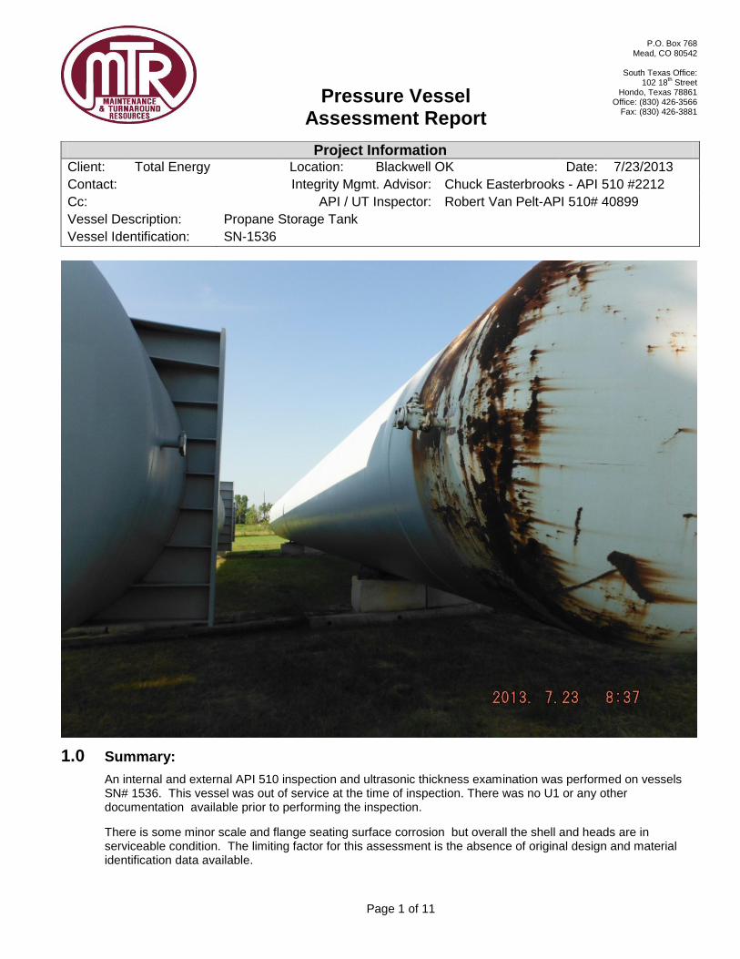
An internal and external API 510 inspection and ultrasonic thickness examination was performed on vessels SN# 1536. This vessel was out of service at the time of inspection. There was no U1 or any other documentation available prior to performing the inspection.
There is some minor scale and flange seating surface corrosion but overall the shell and heads are in serviceable condition. The limiting factor for this assessment is the absence of original design and material identification data available.
Project Information Client: Total Energy Location: Blackwell OK Date: 7/23/2013
Contact: Integrity Mgmt. Advisor: Chuck Easterbrooks - API 510 #2212
Cc: API / UT Inspector: Robert Van Pelt-API 510# 40899
Vessel Description: Propane Storage Tank
Vessel Identification: SN-1536

Pressure Vessel
Assessment Report
P.O. Box 768 Mead, CO 80542
South Texas Office:
102 18th Street
Hondo, Texas 78861 Office: (830) 426-3566
Fax: (830) 426-3881
Page 2 of 11
Table of Contents
1.0 SUMMARY: 1536 1
2.0 REFERENCES: 3
3.0 GENERAL DISCUSSION: 3
4.0 INSPECTION DETAILS: 3
4.1 EXTERNAL INSPECTION: 3 4.2 INTERNAL INSPECTION: 4 4.3 CONCLUSION: 4 4.4 RECOMMENDATIONS: 4
5.0 ULTRASONIC THICKNESS INSPECTION: 5
5.1 SUMMARY INFORMATION: 5 5.2 UT THICKNESS DATA 6
6.0 PICTURES: 8
Pressure Vessel
Assessment Report
P.O. Box 768 Mead, CO 80542
South Texas Office:
102 18th Street
Hondo, Texas 78861 Office: (830) 426-3566
Fax: (830) 426-3881
Page 3 of 11
2.0 References:
API 510 – Pressure Vessel Inspection Code
ASME Section VIII Division 1
ASME Section V
API 579 – Fitness for Service
NBIC – National Board Inspection Code
3.0 General Discussion:
The contents of this report are based on the data acquired during the visual inspection and ultrasonic thickness inspection results. UT data was taken at specific locations to determine the remaining thickness . The internal and external visual inspection results provide an account of the visual condition and presence of any visual degradation.
There was not any historical inspection or original design information available for review that positively identifies the material spec or grade or original thickness.
4.0 Inspection Details:
4.1 External Inspection:
Saddle Supports:
There are 3 saddles supports for this vessel. Each support has a reinforcement band ¼” thick by 9” wide completely encompasses the full circumference of the vessel. The supports are located near each end and in the center. There were no visible distortions and the supports appear to be in serviceable condition.
Shell:
Complete coating failure was evident on the North Head to approximately 5 feet south of the head to shell weld. Coating failure in small ½”- 1” areas throughout the remaining length of the vessel was also observed. There were access platform clips welded to the shell but the platforms were not on site.
Nozzles:
The nozzles necks were in serviceable condition however the flange sealing surfaces had a tightly adhered combination of atmospheric scale and paint approximately 20 mils thick. The pitting was not evaluated on the sealing surface due to the heavy scale build up. Nozzle labeled N3 had a visible RMS finish under the heavy scale while all of the other flange seating surfaces had no visible serrations. There were reinforcement pads installed on the 6” nozzle and the manway. All the repads had metallic threaded plugs installed in their telltale holes. Inspection of the telltale holes could not be performed.
The manway had a heavy atmospheric scale build up on the flange area around the OD of the raised face sealing surface. The sealing surface was in serviceable condition. The scale can be scraped off with a hand scraper. The manway davit arm had been cut off previously leaving only the davit arm hinge clip and a partial remnant of the davit arm inserted into the clip.
Heads:
The north head had significant coating failure extending approximately 5 feet past the head to shell girth seam. The south head had scattered visible paint failure areas up to 1” in diameter throughout.
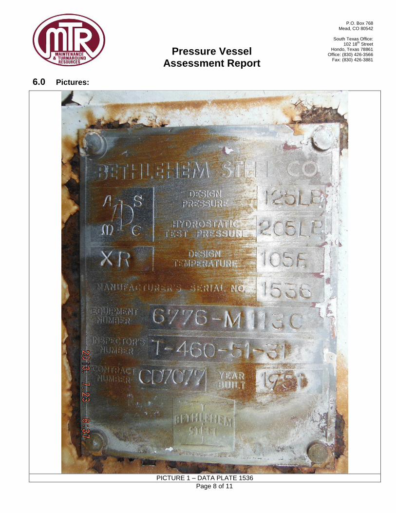
Data Plate:
The data plate was intact and legible.
Pressure Vessel
Assessment Report
P.O. Box 768 Mead, CO 80542
South Texas Office:
102 18th Street
Hondo, Texas 78861 Office: (830) 426-3566
Fax: (830) 426-3881
Page 4 of 11
4.2 Internal Inspection:
Shell & Heads:
Manway: The internal surface of the manway displayed no pitting. It had a light surface scale of approximately 10 mils thick. It did not indicate any signs of bulging, blistering or warping. The ID nozzle to shell weld was full profile with no preferential corrosion visible. The weld surface was similar to the nozzle ID surface.
Shell:
The shell internal surface was generally smooth with no measurable pitting. There was a light surface oxidation throughout the entire ID of the vessel. The welds were full profile and comparable to the shell surface ID.mm There are 3 internal stiffening rings welded to the shell for the entire ID circumference that are ½” thick X 6” in height.
Nozzles:
A 2” nozzle on the north east side had a valve and blind installed. Inspection of this nozzle was limited to the ID surface only, It had a heavy rust and scale build up which impeded the ID inspection of the surface. All nozzles, including threaded couplings, were internally back-welded and have some internal projection. All welds are full and complete with no visible porosity, cracking, or discontinuities that would affect the pressure retaining capabilities. Nozzle necks are free from debris and corrosion. All ID nozzle weld surfaces were comparable to the adjacent shell surfaces.
Internal Distributor Pipe:
A distributor pipe was installed on the south west end of the vessel and traveled to the north for the entire length to the vessel. The north end of the distributor header (approximately 15 foot) had 1/16” holes on the bottom of the pipe. The holes were 2” apart in a linear row. 95% of the holes completely were plugged.
HEADS:
The ID surfaces of the heads were comparable to the shell ID. The head to shell welds were comparable to the shell ID surface.
4.3 Conclusion:
The UT data shows a .080” maximum deviation from the lowest to highest remaining thickness obtained on the shell and .059” deviation on the heads. Pressure vessels in propane service typically were designed with a 0.000” corrosion allowance. The corrosion observed and noted above does not appear to be service related and aside from the gasket surface degradation, is mild in nature and a result of atmospheric corrosion and a period of time out of service without an inert purge.
4.4 Recommendations:
The vessel should be abrasively blasted and painted to mitigate future external corrosion. All flange gasket surfaces should be mechanically cleaned and evaluated to ensure suitability for service.
Without positive identification of the materials used to construct this vessel, procedures complying with API 510 Section 7.7 or NBIC will need to be followed to ascertain the future service limitations, design conditions, and MAWP. Additionally, any applicable rules for the jurisdiction and a future inspection plan will need to be developed in accordance with API 510.
Pressure Vessel
Assessment Report
P.O. Box 768 Mead, CO 80542
South Texas Office:
102 18th Street
Hondo, Texas 78861 Office: (830) 426-3566
Fax: (830) 426-3881
Page 5 of 11
5.0 Ultrasonic Thickness Inspection:
Details:
Straight beam ultrasonic thickness measurements were taken at various separate locations on the shell plate material and the ellipsoidal heads. UT readings were taken utilizing a KB USM GO instrument with a CA-211A ½” single element transducer, calibrated on 1” mild carbon steel step block. There was not a U-1A form or other documentation available to compare UT thickness readings with. The base material was not known during this examination.
The thickness measurements shown below utilize the orientation of the vessel at the time of inspection, whereas the North head is the head with the original data plate affixed to the head.
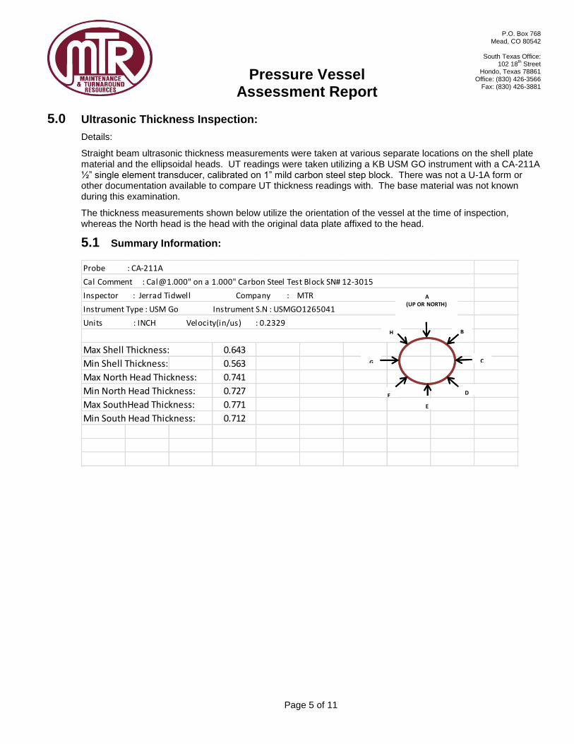
5.1 Summary Information:
Max Shell Thickness: 0.643
Min Shell Thickness: 0.563
Max North Head Thickness: 0.741
Min North Head Thickness: 0.727
Max SouthHead Thickness: 0.771
Min South Head Thickness: 0.712
Instrument Type : USM Go Instrument S.N : USMGO1265041
Units : INCH Velocity(in/us) : 0.2329
Probe : CA-211A
Cal Comment : [email protected]" on a 1.000" Carbon Steel Test Block SN# 12-3015
Inspector : Jerrad Tidwell Company : MTR A(UP OR NORTH)
B
C
D
E
F
G
H
A(UP OR NORTH)
B
C
D
E
F
G
H

Pressure Vessel
Assessment Report
P.O. Box 768 Mead, CO 80542
South Texas Office:
102 18th Street
Hondo, Texas 78861 Office: (830) 426-3566
Fax: (830) 426-3881
Page 6 of 11
5.2 UT Thickness Data
Bands A B C D E F G H
1 0.598 0.585 0.59 0.597
2 0.632 0.613 0.639 0.633
3 0.596 0.581 0.598 0.598
4 0.594 0.597 0.594 0.592
5 0.631 0.633 0.614 0.61
6 0.588 0.59 0.589 0.585
7 0.582 0.586 0.563 0.575
8 0.637 0.631 0.614 0.63
9 0.594 0.596 0.57 0.586
10 0.601 0.604 0.598 0.592
11 0.643 0.638 0.627 0.616
12 0.603 0.6 0.599 0.593
13 0.584 0.58 0.573 0.581
14 0.61 0.607 0.614 0.616
15 0.577 0.571 0.568 0.578
16 0.574 0.579 0.573 0.573
17 0.621 0.616 0.617 0.608
18 0.593 0.594 0.593 0.59
19 0.57 0.57 0.567 0.57
20 0.589 0.584 0.59 0.589
21 0.568 0.565 0.565 0.569
22 0.589 0.592 0.585 0.577
23 0.634 0.633 0.623 0.613
24 0.603 0.604 0.596 0.587
25 0.587 0.581 0.586 0.593
26 0.617 0.604 0.627 0.631
27 0.583 0.577 0.579 0.589
28 0.573 0.574 0.574 0.572
29 0.61 0.609 0.609 0.598
30 0.57 0.572 0.566 0.566
31 0.573 0.572 0.566 0.573
32 0.608 0.607 0.608 0.616
33 0.583 0.584 0.57 0.576
34 0.574 0.578 0.572 0.58
35 0.608 0.609 0.607 0.603
36 0.579 0.613 0.58 0.584

Pressure Vessel
Assessment Report
P.O. Box 768 Mead, CO 80542
South Texas Office:
102 18th Street
Hondo, Texas 78861 Office: (830) 426-3566
Fax: (830) 426-3881
Page 7 of 11
UT Data (Cont.):
Bands A B C D E F G H
37 0.736 0.739 0.734 0.741
38 0.731 0.727 0.732 0.734
39 0.737 0.771 0.712 0.754
40 0.729 0.729 0.722 0.735
41 0.424 0.424
42 1.005 1.006 1.008 1.009
43 0.42 0.432 0.428 0.413
44 0.427 0.418 0.416 0.429
45 0.603 0.586 0.598 0.598
46 0.426 0.429 0.428 0.417
47 0.429 0.425 0.435 0.423
North Head
South Head
Nozzles
Pressure Vessel
Assessment Report
P.O. Box 768 Mead, CO 80542
South Texas Office:
102 18th Street
Hondo, Texas 78861 Office: (830) 426-3566
Fax: (830) 426-3881
Page 8 of 11
6.0 Pictures:
PICTURE 1 – DATA PLATE 1536

Pressure Vessel
Assessment Report
P.O. Box 768 Mead, CO 80542
South Texas Office:
102 18th Street
Hondo, Texas 78861 Office: (830) 426-3566
Fax: (830) 426-3881
Page 9 of 11
head corrosion 1536 head corrosion 1536
Saddle Support Reinforcement strap for saddle

Pressure Vessel
Assessment Report
P.O. Box 768 Mead, CO 80542
South Texas Office:
102 18th Street
Hondo, Texas 78861 Office: (830) 426-3566
Fax: (830) 426-3881
Page 10 of 11
Davit Arm bracket Man Way
Corroded Flange Face Corroded Flange Face

Pressure Vessel
Assessment Report
P.O. Box 768 Mead, CO 80542
South Texas Office:
102 18th Street
Hondo, Texas 78861 Office: (830) 426-3566
Fax: (830) 426-3881
Page 11 of 11
Couplings welded to shell Repad pluged with threaded plug
Distributor Pipe ID Stiffener support for saddles (typ 3)