pressure transient analysis of a well penetrating a filled...
TRANSCRIPT

Seediscussions,stats,andauthorprofilesforthispublicationat:https://www.researchgate.net/publication/303635081
PressureTransientAnalysisofaWellPenetratingaFilledCavityinNaturallyFracturedCarbonateReservoirs
ArticleinJournalofPetroleumScienceandEngineering·May2016
DOI:10.1016/j.petrol.2016.05.037
CITATION
1
READS
71
5authors,including:
Someoftheauthorsofthispublicationarealsoworkingontheserelatedprojects:
Anefficientnumericalsimulationfordiscretefracturemodelbasedonmixedmulti-scalefinite
elementmethodViewproject
ZhaoqinHuang
ChinaUniversityofPetroleum,Qingdao,China
52PUBLICATIONS188CITATIONS
SEEPROFILE
Yu-ShuWu
ColoradoSchoolofMines
276PUBLICATIONS3,397CITATIONS
SEEPROFILE
AllcontentfollowingthispagewasuploadedbyYu-ShuWuon13June2016.
Theuserhasrequestedenhancementofthedownloadedfile.Allin-textreferencesunderlinedinblueareaddedtotheoriginaldocumentandarelinkedtopublicationsonResearchGate,lettingyouaccessandreadthemimmediately.

Journal of Petroleum Science and Engineering 145 (2016) 392–403
Contents lists available at ScienceDirect
Journal of Petroleum Science and Engineering
http://d0920-41
n CorrE-m
journal homepage: www.elsevier.com/locate/petrol
Pressure transient analysis of a well penetrating a filled cavity innaturally fractured carbonate reservoirs
Bo Gao a, Zhao-Qin Huang a,b,n, Jun Yao a, Xin-Rui Lv c, Yu-Shu Wub
a China University of Petroleum (East China), Qingdao 266580, Chinab Colorado School of Mines, Golden 80401, USAc Research Institute of Petroleum Exploration and Development, Sinopec, Beijing 100083 China
a r t i c l e i n f o
Article history:Received 24 September 2015Received in revised form30 April 2016Accepted 26 May 2016Available online 27 May 2016
Keywords:Naturally fractured reservoirWell testingThe Barree‐Conway modelFilled cavityDual-porosity model
x.doi.org/10.1016/j.petrol.2016.05.03705/& 2016 Elsevier B.V. All rights reserved.
esponding author at: Colorado School of Minail address: [email protected] (Z.-Q. Hu
a b s t r a c t
Naturally fractured carbonate reservoirs have been discovered in many oilfields around the world and arecharacteristic of a complex, heterogeneous porosity system. The presence of large-scale cavities will havea noticeable effect on the transient pressure behavior, especially, when a well is drilled through them.The cavities are usually filled with loose materials, such as gravel, sand, and mud, due to the physical orchemical processes. Therefore fluid flow in a filled cavity may range from low-velocity Darcy flow tohigh-velocity non-Darcy flow. It is necessary to incorporate cavity filling effect in the type curvematching for flow behavior in fractured carbonate reservoirs. The objective of this work is to develop anefficient well testing model to analyze and interpret the transient pressure responses observed in anaturally fractured carbonate reservoir, in which a well is drilled through a filled cavity. To this end, aradial composite reservoir model including the inner and outer regions with different characteristics isproposed. The inner region is a filled cavity with a well drilled into. The outer region, a naturally frac-tured reservoir, is considered as a dual-porosity model in this work. The Barree-Conway model, initiallyproposed for a proppant-packed fracture, is applied to simulate the non-Darcy flow in the inner region.The corresponding mathematical model is developed, and a numerical solution is then obtained based onthe finite difference method, which is further verified by the analytical solution under simplified flowcondition. Several standard log-log type curves are provided to reveal the flow characteristics. The flowprocess is shown to have six flow stages in general. Subsequently, sensitivity analyses of the type curvesare carried out. The calculated results show that the characteristics of the well testing type curves areinfluenced significantly by non-Darcy coefficients, the size of the filled cavity, and the petrophysicproperty ratio between inner and outer areas. Finally, the proposed model is applied to analyze andinterpret two field testing examples.
& 2016 Elsevier B.V. All rights reserved.
1. Introduction
In the past decade, naturally fractured carbonate reservoirshave been discovered and developed in China (Kang et al., 2005;Li, 2013; Li, 2013; Yao et al., 2010). This kind of carbonate reservoircommonly has complex pore structures and presents specialchallenges not found in sandstone reservoirs (Camacho-Velazquezet al., 2005; Huang et al., 2010; Popov et al., 2009a). There arethree types of pores in naturally fractured carbonate reservoirs,i.e., matrix, fractures and vugs (Huang et al., 2013, 2011; Popovet al., 2009b). As observed in the outcrops of Tahe and Tarim oil-fields in west China, however, some large cavities also exist informations (as shown in Fig. 1). The sizes of these cavities may
es, Golden 80401, USA.ang).
range from several meters even to tens of meters. The recent workindicates that fractured-cavity reservoirs are the major type inTahe oilfield (Li, 2012), and there are a number of wells drilled inlarge cavities, which can be identified by string of beads-likeseismic reflection structures and abnormal wave resistance (Li,2012; 2013).
The transient pressure behaviors in naturally fractured carbo-nate reservoirs are very different from that in the conventionalsandstone (Camacho-Velazquez et al., 2005; Jia et al., 2013; Wuet al., 2011a; Yang et al., 2005). If a well is drilled into a cavity, thecorresponding well testing response will be more complicated. Inthe previous works, cavities and large-scale vugs are usuallyconsidered as voids of free-fluid flow regions, in which the Stokesequation is applied to describe the fluid flow (Arbogast and Go-mez, 2009; Arbogast and Lehr, 2006; Peng et al., 2009). And thenthe main challenge of fluid flow modeling focuses on the couplingof free flowwith porous flow (Gulbransen et al., 2010; Huang et al.,

Nomenclature
A1 undetermined coefficient in the analytical solutionBi undetermined coefficient in the analytical solution,
i¼1,2B volume factor, m3/m3
C wellbore storage coefficient, m3/PaCi total compressibility, i¼m,f,c,1/PaI0 the first kind of 0-order imaginary argument Bessel
functionsI1 the first kind of 1-order imaginary argument Bessel
functionsK0 the second kind of 0-order imaginary argument Bessel
functionsK1 the second kind of 1-order imaginary argument Bessel
functionsaij element of the coefficient matrix in the analytical so-
lution, i,j¼1,2,3h formation thickness, mki Darcy permeability of matrix, fracture and the filling
cavity, i¼m,f,c, μm2
kmin the minimum permeability at high velocitykmr The minimum permeability ratio, kmin/kpi fluid pressure, i¼m,f,c, Papw bottom hole pressure, Pa∇p pressure gradientq flow rate at wellhead , m3/srw wellbore radius, mrc radius of the filling cavity, mre drainage radius, ms skin factort time, sv fluid flow velocity, m/sz Laplace space variable
Greek letters
α inter-porosity flow coefficientγ permeability ratio of the two regionsδN modified high-velocity non-Darcy coefficientδ dimensionless modified high-velocity non-Darcy
coefficientη diffusivity ratio between the two regionsλ inter-porosity flow shape factorμ dynamic viscosity of the fluid, Pa � sρ the fluid density, kg/m3
τ the inverse of characteristic length, 1/mτD dimensionless characteristic lengthϕi porosity, i¼m,f,cω elastic storage ratio
Dimensionless parameters
CD dimensionless wellbore storage coefficientpiD dimensionless pressure, i¼m,f,cpwD dimensionless wellbore pressurep̃iD dimensionless pressure in Laplace space, i ¼m,f,cqwD dimensionless productionrD dimensionless radiustD dimensionless time
Superscript
n the previous time stepnþ1 the current time step
Subscript
c cavityf fractured systemm matrix
Fig. 1. Typical outcrops of Tahe and Tarim oilfields in west China.
B. Gao et al. / Journal of Petroleum Science and Engineering 145 (2016) 392–403 393
2011, 2010; Peng et al., 2009; Popov et al., 2009a, 2009b). Thecorresponding modeling results indicate that the cavities or vugscan be considered as some equipotential bodies, in which the fluidpressure is equal due to the infinite permeability. Based on this
point, Liu and Wang (2012) and Yang et al. (2011) developed asimplified composite well testing model, in which the cavity istreated as an equipotential body and the outer fractured region ismodelled by a dual-porosity model. Cheng et al. (2009) has

B. Gao et al. / Journal of Petroleum Science and Engineering 145 (2016) 392–403394
proposed a similar model in which the cavity is considered as anexpanded wellbore.
However, the cavities are commonly filled with loose material,such as sand, gravel and mud (Popov et al., 2009a, 2009b), as il-lustrated in Fig. 1. Recently, Hu et al. (2014) and Zhang et al. (2012)studied the cavity filling characteristics based on the outcrops innorthern Tarim basin and the well logs of Tahe oilfield. The resultsindicate that the effects of cavity filling can play a crucial role inthe overall response of the reservoirs. To this end, Zhang et al.(2009) developed a well test interpretation model for naturallyfractured reservoir considering a well drilled in a large cavity. Intheir flow model, the cavity was treated as a Darcy flow regionwith higher permeability than the outer porous zone. Never-theless, they did not make further analysis of the cavity fillingcharacterization and the corresponding effects on the transientpressure behavior in fractured reservoirs. Moreover, the fillingmaterial may be very different as mentioned above, and the di-mensions of the loose material particles may range from milli-meter scale to centimeter scale even meter scale. As a result, thefluid flow regime in filled cavities may range from low-velocityDarcy flow to high-velocity non-Darcy flow dependent on thefilling characteristics.
The effects of high-velocity, non-Darcy flow in porous mediahave been investigated by using Forchheimerequation (Forchheimer, 1901) for decades (Evans et al., 1987;Huang and Ayoub, 2008; Wu, 2001; Ye et al., 2014). However, theForchheimer equation has been found to be inadequate for mod-eling the non-Darcy phenomena over the entire flow velocityrange (Barree and Conway, 2009, 2004; Huang and Ayoub, 2008;Ranjith and Viete, 2011). Furthermore, when we consider non-Darcy flow in a filled cavity, it is not convenient to apply theForchheimer equation because its non-Darcy coefficient is not di-rectly related to the cavity filling characteristics, such as the meanequivalent diameter of the filled particles. Recently, Barree andConway (2009, 2004) developed a new physical-based model fordescribing the non-Darcy flow based on experimental and fielddata. This model has been applied to the single- and multi-phasenon-Darcy flow analysis in porous media (Al-Otaibi and Wu, 2010;Wu et al., 2011b; Zhang and Yang, 2014a, 2014b). The further la-boratory researches and analyses (Lai et al., 2012; Lopez-
oil well
caprock
loose material-filled cavity
carbonate
oil well
filled cavity
naturallvuggy
Fig. 2. Schematic of a well drilled into a filled cavity within naturally fractured reservoir (
Hernandez, 2007) indicate that the Barree-Conway model candescribe the non-Darcy flow behavior from low to high flow rates.Moreover, the Barree-Conway model was proposed for the prop-pant-packed hydraulic fracture initially so a characteristic lengthparameter of the filled particles exists apparently in the model.From this point of view, it is convenient and reasonable to use theBarree-Conway model to consider the cavity filling effects.
The objective of this work is to develop an efficient well testinganalysis model, which is suitable for naturally fractured reservoirswith a well drilled into a large-scale cavity. We propose a com-posite reservoir model: (1) the filled cavity is treated as the innerregion, in which a well locates at the center and the Barree-Con-way model is applied to describe the fluid flow; (2) the outer re-gion consists of naturally fractured porous media, in which thedual-porosity model is applied. This paper is organized as follows.The physical model and the corresponding mathematical welltesting model are developed for the composite reservoir in Section2. Then in Section 3, an efficient finite difference numericalscheme is applied to solve this model. The transient pressurecurves and the corresponding flow characteristics are providedand the effects of some key parameters are discussed. As examplesof model validation and application, two field cases are studiedbased on the proposed model in Section 4. Finally, several keyremarks are concluded in Section 5.
2. Physical concept and mathematical model
2.1. Physical concept
The carbonate reservoir in Tahe and Tarim oilfields of China is atypical example of reservoirs composed of matrix, fracture and vugsystems, called as naturally fractured vuggy carbonate reservoir.Typical outcrops in Tahe and Tarim oilfields are shown in Fig. 1.Fig. 2 shows the physical schematic model of a well drilled into afilled cavity within a fractured carbonate reservoir. As shown inFigs. 2-b and 2-c, the physical model is divided into two disparateparts: one is the interior region, i.e., the filled cavity; and the otheris the outer region, i.e., the naturally fractured reservoir. In theouter part, the vug system is usually connected with fracture
y fracturedreservoir
h
rc
re
filled cavity
naturally fracturedvuggy reservoir
a), and its corresponding 3�D physical model (b) and areal 2�D physical model (c).

B. Gao et al. / Journal of Petroleum Science and Engineering 145 (2016) 392–403 395
system, forming the main pathway for the global flow. Therefore,the whole outer region is treated as a conventional double-por-osity model (Warren and Root, 1963) in this work. Moreover, thefollowing assumptions are made for the physical model:
1. The well produces oil at a fixed volumetric rate and the re-servoir has a uniform pressure distribution before production.
2. The Barree-Conway model is applied to describe the non-Darcyflow in the filled cavity (i.e. the interior region). The outer re-gion, i.e. the fractured reservoir, is a double porosity model. Thefracture-vug system is the main pathway in which linear Darcyflowmodel is applied, and the matrix system is only regarded asthe source providing fluid to the fracture-vug system.
3. Both fluid and rock are lightly compressible with constantcompressibility coefficients.
4. Gravity is neglected and no chemical or physical reactionshappen, and the isothermal flow process is assumed.
5. Both the top and bottom boundaries of the reservoir are closedor impermeable.
2.2. Dimensionless mathematical model
The original mathematical model is shown in Appendix A. Inorder to obtain the dimensionless one, a group of dimensionlessparameters should be defined first and then substituted into theprevious mathematical equations. Definitions of the dimensionlessparameters are listed in Table 1. The last three dimensionlessparameters, as well as minimum permeability ratio kmr, are ofgreat significance in this study. We will explore their influences onbottom hole pressure response, together with their practicalmeanings in Section 3. The dimensionless mathematical modelwill be written as follows:
1. Non-Darcy flow region: < <r r1 D cD
ηγ δ∂∂
− ∂∂
∂∂
=( )
⎛⎝⎜
⎞⎠⎟
p
t r rr
p
r1
01
cD
D D DD
cD
D
2. Darcy flow region: < <r r rcD D eD
( )
( )( )
ω λ
ω λ
∂∂
− ∂∂
∂∂
+ − =
−∂∂
− − =( )
⎧
⎨⎪⎪
⎩⎪⎪
⎛⎝⎜
⎞⎠⎟
p
t r rr
p
rp p
p
tp p
10
1 02
fD
D D DD
fD
DfD mD
mD
DfD mD
3. Initial condition
( ) ( ) ( )= = = ( )p r p r p r, 0 , 0 , 0 0 3cD D fD D mD D
Table 1.Dimensionless parameters.
Parameters Definitions
Dimensionless radius, rD ( )= −r r r e/ sD w
Dimensionless time, tD ( )ϕ ϕ μ= +⎡⎣ ⎤⎦t k t c c r/D f m m f f w2
Dimensionless pressure, piD ( ) ( )π μ= − =p k h p p qB i m f2 / , , ci iD f 0
Dimensionless wellbore storagecoefficient, CD
π ϕ=C C hr c/2D w2
c c
Fluid storage capacitance coefficient,ω
( )ω ϕ ϕ ϕ= +c c c/f f m m f f
Inter-porosity flow factor, λ ( )λ α= k k r/m f w2
Dimensionless characteristic length,τD
τ ρ π μτ= −qB h r e/2 sD w
Diffusivity ratio between the tworegions, η
( )η ϕ ϕ ϕ= +c c c/c c m m f f
Ratio of the permeability betweentwo regions, γ
γ = k k/f c
4. Inner boundary condition
δ
δ
−∂∂
=
= −∂∂
( )
=
=
⎧
⎨⎪⎪⎪
⎩⎪⎪⎪
⎛⎝⎜
⎞⎠⎟
Cdp
dt
p
r
p p sp
r
1
4
r
r
DwD
D
cD
D 1
wD cDcD
D 1
D
D
5. Coupling interface conditions
δ γ
=∂∂
=∂∂
=
( )
⎧⎨⎪⎩⎪
p p
p
r
p
rr r, at
5
cD fD
cD
D
fD
D
D cD
6. Outer boundary condition
∂∂
= =
= =
= ( )
=
= =
⎧
⎨⎪⎪⎪
⎩⎪⎪⎪
p
rr r
p p r
r
0 closed boundary
0 constant pressure boundary
6
r r
r r r r
fD
DeD
fD mD
eD
eD
eD eD
where rcD is the interface between two regions; pwD is di-mensionless wellbore pressure; δ is dimensionless modified high-velocity coefficient and given as:
( )δτ
= +−
+ ( )k
k
q r
1
1 / 7mr
mr
D rD D
Here, qrD is the dimensionless production rate and the follow-ing is satisfied.
ττ τ τ= + + + −
( )
⎡
⎣⎢⎢⎢
⎛⎝⎜
⎞⎠⎟
⎤
⎦⎥⎥⎥
q
rk
dp
drk
dp
dr
dp
dr1
21 1 4
8
rD
D Dmr D
cD
Dmr D
cD
D
2
DcD
D
Then, δ can be evaluated by using Eq. (7).
3. Type curves and analysis
3.1. Verification of the numerical solution
The above mathematical model is strong non-linear, so it isdifficult to get an analytical solution. Therefore, numerical solutionis preferred in this work. Before analysing the well testing curvesobtained numerically, the numerical method and code in this pa-per are verified by two ways. The first is using Li's data (Li et al.,2013) of homogeneous reservoir as reference to show our non-Darcy solution method is right. Secondly, analytical solution of acomposite radial reservoir, in which Darcy flow controls the wholeregion, is used to check the numerical method and code. The nu-merical solution and analytical solution processes are shown inAppendix B detailedly.
Li has studied the Barree-Convey model in homogeneous re-servoir and compared it with conditional Forchheimer non-Darcyequation. The reference solution shown in Fig. 3 is one of Li's so-lution data sets which has been published. We first use the non-Darcy part of our model to match it. The dimensionless parametersare:
τ= = = =C e k r100, 0.1, 3.0, 5000sD
2mr D cD
Obviously, the compared result indicates that the mathematicalmodel and numerical method of the non-Darcy part are valid.
Next in the second verification, we also consider a composite
1E-2
1E-1
1E+0
1E+1
1E+2
1E-2 1E-1 1E+0 1E+1 1E+2 1E+3 1E+4 1E+5
p,p
'·t/C
t /C
reference solution: pressurecalculated solution: pressurereference solution: pressure derivationcalculated solution: pressure derivation
Fig. 3. Comparison of reference solution by Li and calculated solution in this work.
Table 2.Dimensionless parameters.
Parameters Value
Minimum permeability, kmr 0.01Dimensionless characteristic length, τD 10Dimensionless radius of the filling cavity, rcD 40Ratio of the permeability of fracture to that of the filling cavity, γ 0.01Diffusivity ratio between inner and outer part, η 5Capacitance coefficient, ω 0.2Fracture–Matrix inter-porosity coefficient, λe�2s 10�6
Dimensionless wellbore storage coefficient, CDe2s 100
1E-1
1E+0
1E+1
1E+2
1E+3
1E-1 1E+0 1E+1 1E+2 1E+3 1E+4 1E+5 1E+6 1E+7 1E+8
pp
'·t/C
t /C
numerical solution: pressureanalytical solution: pressurenumerical solution: pressure derivationanalytical solution: pressure derivation
Fig. 4. Well testing curves for comparison between analytical and numericalsolutions.
1E-1
1E+0
1E+1
1E+2
1E+3
1E-1 1E+1 1E+3 1E+5 1E+7
p, p
'· t
/C
t /C
infinite boundaryclosed boundaryconstant pressure boundary
I VIVIIIII VI
pwD
p'wD · tD/CD
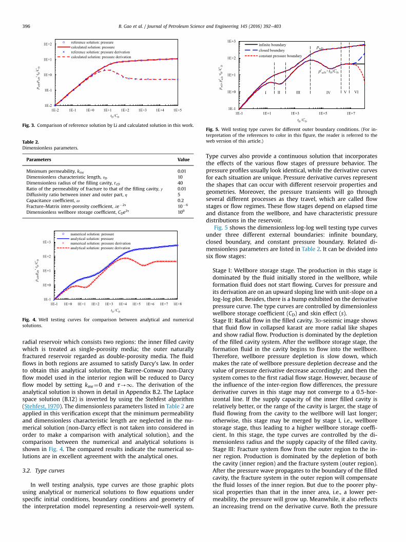
Fig. 5. Well testing type curves for different outer boundary conditions. (For in-terpretation of the references to color in this figure, the reader is referred to theweb version of this article.)
B. Gao et al. / Journal of Petroleum Science and Engineering 145 (2016) 392–403396
radial reservoir which consists two regions: the inner filled cavitywhich is treated as single-porosity media; the outer naturallyfractured reservoir regarded as double-porosity media. The fluidflows in both regions are assumed to satisfy Darcy's law. In orderto obtain this analytical solution, the Barree-Conway non-Darcyflow model used in the interior region will be reduced to Darcyflow model by setting kmr¼0 and τ-1. The derivation of theanalytical solution is shown in detail in Appendix B.2. The Laplacespace solution (B.12) is inverted by using the Stehfest algorithm(Stehfest, 1970). The dimensionless parameters listed in Table 2 areapplied in this verification except that the minimum permeabilityand dimensionless characteristic length are neglected in the nu-merical solution (non-Darcy effect is not taken into considered inorder to make a comparison with analytical solution), and thecomparison between the numerical and analytical solutions isshown in Fig. 4. The compared results indicate the numerical so-lutions are in excellent agreement with the analytical ones.
3.2. Type curves
In well testing analysis, type curves are those graphic plotsusing analytical or numerical solutions to flow equations underspecific initial conditions, boundary conditions and geometry ofthe interpretation model representing a reservoir-well system.
Type curves also provide a continuous solution that incorporatesthe effects of the various flow stages of pressure behavior. Thepressure profiles usually look identical, while the derivative curvesfor each situation are unique. Pressure derivative curves representthe shapes that can occur with different reservoir properties andgeometries. Moreover, the pressure transients will go throughseveral different processes as they travel, which are called flowstages or flow regimes. These flow stages depend on elapsed timeand distance from the wellbore, and have characteristic pressuredistributions in the reservoir.
Fig. 5 shows the dimensionless log-log well testing type curvesunder three different external boundaries: infinite boundary,closed boundary, and constant pressure boundary. Related di-mensionless parameters are listed in Table 2. It can be divided intosix flow stages:
Stage I: Wellbore storage stage. The production in this stage isdominated by the fluid initially stored in the wellbore, whileformation fluid does not start flowing. Curves for pressure andits derivation are on an upward sloping line with unit-slope on alog-log plot. Besides, there is a hump exhibited on the derivativepressure curve. The type curves are controlled by dimensionlesswellbore storage coefficient (CD) and skin effect (s).Stage II: Radial flow in the filled cavity. 3D-seismic image showsthat fluid flow in collapsed karast are more radial like shapesand show radial flow. Production is dominated by the depletionof the filled cavity system. After the wellbore storage stage, theformation fluid in the cavity begins to flow into the wellbore.Therefore, wellbore pressure depletion is slow down, whichmakes the rate of wellbore pressure depletion decrease and thevalue of pressure derivative decrease accordingly; and then thesystem comes to the first radial flow stage. However, because ofthe influence of the inter-region flow differences, the pressurederivative curves in this stage may not converge to a 0.5-hor-izontal line. If the supply capacity of the inner filled cavity isrelatively better, or the range of the cavity is larger, the stage offluid flowing from the cavity to the wellbore will last longer;otherwise, this stage may be merged by stage I, i.e., wellborestorage stage, thus leading to a higher wellbore storage coeffi-cient. In this stage, the type curves are controlled by the di-mensionless radius and the supply capacity of the filled cavity.Stage III: Fracture system flow from the outer region to the in-ner region. Production is dominated by the depletion of boththe cavity (inner region) and the fracture system (outer region).After the pressure wave propagates to the boundary of the filledcavity, the fracture system in the outer region will compensatethe fluid losses of the inner region. But due to the poorer phy-sical properties than that in the inner area, i.e., a lower per-meability, the pressure will grow up. Meanwhile, it also reflectsan increasing trend on the derivative curve. Both the pressure

1E-1
1E+0
1E+1
1E+2
1E+3
1E-1 1E+0 1E+1 1E+2 1E+3 1E+4 1E+5 1E+6 1E+7 1E+8
p,p
'·t/C
t /C
Darcy: pressurenon-Darcy+Darcy: pressureDarcy: pressure derivationnon-Darcy+Darcy: pressure derivation
Fig. 6. Well testing curves for different models.
1E-1
1E+0
1E+1
1E+2
1E+3
1E-1 1E+0 1E+1 1E+2 1E+3 1E+4 1E+5 1E+6 1E+7 1E+8
p,p
'·t/ C
t /C
pressure: rc=1mpressure: rc=2mpressure: rc=3mpressure derivation: rc=1mpressure derivation: rc=2mpressure derivation: rc=3m
Fig. 7. Well testing curves for different cavity sizes.
1E-1
1E+0
1E+1
1E+2
1E+3
1E-1 1E+0 1E+1 1E+2 1E+3 1E+4 1E+5 1E+6 1E+7
p, p
'·t
/C
t /C
pressure: kmr=0.01pressure: kmr=0.2pressure: kmr=0.8pressure derivation: kmr=0.01pressure derivation: kmr=0.2pressure derivation: kmr=0.8
Fig. 8. Well testing curves for different kmr .
B. Gao et al. / Journal of Petroleum Science and Engineering 145 (2016) 392–403 397
and its derivative curves ascend to a higher value. And the lar-ger the difference, the sharper the type curves in this stage willbe. In this stage, the type curves are controlled by the ratio ofthe permeability of fracture to that of the filling cavity.Stage IV: Inter-porosity flow stage of matrix system to fracturesystem. Production is dominated by the depletion of the tworegions, including the filled cavity, the fracture system and thematrix system. The pressure derivative curve is concave, whichis a reflection of the inter-porosity flow of matrix to fracturesystem. Physical processes that occur during this inter-porosityflow stage are: wellbore pressure depletion is hindered due tofluid supplement from matrix system to the fracture system,which makes the rate of wellbore pressure depletion decreaseand reflects a decrease value of the pressure derivative; how-ever, the fluid supplement declines as the pressure depletion ofthe matrix system, thus resulting an increasing value of thepressure derivative accordingly. Therefore, the wellbore pres-sure derivative curve in the inter-porosity flow stage is a typicalconcave shape. In this stage, the type curves are controlled byinter-porosity flow factor.Stage V: Radial flow stage of the whole system. Production isdominated by the depletion of both regions. The inter-porosityflow of matrix to fracture system showed in stage IV has stop-ped. The pressures of the whole system have gone up to a stateof dynamic balance. It has come to a whole radial flow state,which is showed on the pressure derivative curve with a hor-izontal line with a non-0.5 value because of the difference ofphysical properties of the two regions. If the permeability of thefracture system is equal or higher than that of the filled cavity,this value may be close to 0.5 or even lower.Stage VI: External boundary response stage. The pressure wavehas arrived at the external boundary of the reservoir. Differentexternal boundaries yield different curve shapes. As shown inFig. 5, the blue, green and red lines denote the closed boundary,infinite boundary and constant pressure boundary, respectively.For a constant pressure boundary: pressure depletion of thereservoir caused by well production is suddenly supplemented,which makes the rate of wellbore pressure depletion slightlydecrease and the value of the pressure derivative decreaseaccordingly; for a closed boundary: pressure depletion of thereservoir without the peripheral energy supplement is aggra-vated, which makes the rate of wellbore pressure depletionswiftly increase and the value of the pressure derivativeincrease accordingly. In this stage, the type curves are con-trolled by the dimensionless radius of external boundary.
Of course, the shape of the well testing curves will change withthe different situations, in which different model parameters areused. This will be discussed in detail in the next.
3.3. Comparison of non-Darcy flow and Darcy flow in the filledcavity
Zhang et al. (2009) have also developed a well test model fornaturally fractured carbonate reservoir considering a well drilledinto a large-scale cavity, in which Darcy flow model was applied.Therefore, it is necessary to compare the fluid flow behavior ofDarcy flow model to the Barree-Conway non-Darcy model, whichare used in the filled cavity respectively. Related dimensionlessparameters are the same as that listed in Table 2. As shown inFig. 6, the pressure curves as well as its derivatives are in a similartendency when different flow equations are applied. However, thebottom-hole pressure drop increases significantly in the first twoflow stages when non-Darcy flow model is used. Meanwhile, thetwo flow stages in the inner region are relatively delayed for non-Darcy flow model. This is due to the larger flow resistance at
higher fluid flow velocity. Besides the viscosity resistance, theadditional inertial term has been included in the Barree-Conwaymodel as well as Forchheimer equation. Actually, the Barree-Conway model is a general equation to describe the entire range offlow regimes from low-velocity Darcy flow to high-velocity non-Darcy flow. So it is convenient to use this model to describe thefluid flow in a filled cavity with different filling cases.
Fig. 7 shows the effect of different size of a filled cavity on thetype curves. The results indicate that a larger cavity provides en-ough time to represent a relatively completed flow pattern asshown in Fig. 7. In other words, the nonlinear flow in a small-radius-filling cavity will be easily overlapped by wellbore storagestage, resulting in a larger wellbore storage coefficient, especiallywhen the cavity has a poor filling. This is the case of the researchworks developed by (Cheng et al., 2009; Liu and Wang, 2012; Yanget al., 2011).
3.4. Influences of non-Darcy parameters
The Barree-Conway model describes the fluid flow in a filledcavity using two non-Darcy parameters: kmr and τD (Note that τD isrelated to adverse characteristic length). Figs. 8 and 9 show theinfluences of the different parameters value on the transient

1E-1
1E+0
1E+1
1E+2
1E+3
1E-1 1E+1 1E+3 1E+5 1E+7
p, p
'·t
/C
t /C
pressure: τD=10pressure: τD=5pressure: τD=1pressure derivation: τD=10pressure derivation: τD=5pressure derivation: τD=1
Fig. 9. Well testing curves for different τD.
1E-1
1E+0
1E+1
1E+2
1E+3
1E-1 1E+0 1E+1 1E+2 1E+3 1E+4 1E+5 1E+6 1E+7
p, p
'·t
/C
t /C
pressure: γ=0.01pressure: γ=0.1pressure: γ=1pressure derivation: γ=0.01pressure derivation: γ=0.1pressure derivation: γ=1
Fig. 10. Well testing curves for different γ.
1E-1
1E+0
1E+1
1E+2
1E+3
1E-1 1E+0 1E+1 1E+2 1E+3 1E+4 1E+5 1E+6 1E+7
p, p
'·t
/ C
t /C
pressure: η=0.1pressure: η=1pressure: η=5pressure derivation: η=0.1pressure derivation: η=1pressure derivation: η=5
Fig. 11. Well testing curves for different η.
B. Gao et al. / Journal of Petroleum Science and Engineering 145 (2016) 392–403398
pressure behavior. Related dimensionless parameters are listed inTable 2 except the dimensionless cavity radius, which is set to 30.The results show that the bottom-hole pressure drop rises and theflow stages shift right with the decrease of kmr and increase of τD.As a smaller kmr and a larger τD, varying inversely with τ, re-presents a stronger non-Darcy effect. kmr is the minimum per-meability ratio related to the minimum permeability at high flowrate when non-Darcy flow occurs. Various explanations for itsphysical meaning have been advanced in different literature,mainly including two mechanisms, which are both associated withthe pore structure (Barree and Conway, 2004).
(1) Due to the different filling materials and compaction degrees,the pore structures in a filled cavity may vary dramatically. Innormal porous media flow, the fluid will accelerate throughthe relatively narrow pores and inversely decelerate whenpassing larger ones. Such repeated changes in velocity mustlead to inertial losses, which are responsible for the decreasein apparent permeability associated with non-Darcy flow.Edwards et al. (1990) suggest that at higher rates, the flow willkeep a better defined streamlines in the whole body, ratherthan become slower when entering larger pores. As a result,the inertial loses introduced by changing velocity will beminimized. The system will approach a nearly constantapparent permeability.
(2) Another exploration is that at low rate, most part of the totalflow capacity is dominated by large pore channels. While asflow rate increases, the flow will divert to smaller pores suc-cessively, thus reaching a more uniform velocity distributionin the system and compensating for the inertial losses.Therefore, if the pore size ranges in a narrow scale, the inertiallosses will be small accordingly. A uniform velocity distribu-tion will be easily to be satisfied and the minimum perme-ability may approximate the real permeability. Inversely, theminimum permeability will be very small if the pore structureis quite complex.
So the parameter, kmr, can be used to describe the complexity ofthe pore structure. A smaller kmr represents more heterogeneousfilling and compaction in a cavity, and a larger flow resistance. Thecharacteristic length parameter, τ, is related to the mean particlediameter of the filling materials. So it can be used to describe thecharacteristic dimension of the filling material particles. A smaller τrepresents a larger size of the filling particles. Therefore, the specificsurface is smaller, and the flow rate is higher. And then, the fluid flowin a filled cavity will deviate more from linear Darcy flow.
3.5. Influences of rock properties of inner and outer regions
Fig. 10 shows well testing curves with different permeabilityratios γ. Related dimensionless parameters chosen here are the
same as those in Section 3.4. γ¼1 means the fracture system of theouter region has the same permeability as that of the filled cavity.In this case, the phenomenon of obvious pressure drop increases,as expounded above, does not appear due to the same perme-ability. Moreover, the fluid supply process from the cavity happenslater. While γo1, the smaller value of parameter γ means thelarger difference of the rock properties between the two regions.The change of the bottom-hole pressure drop is more evident andthe flow stages are more remarkable.
Fig. 11 shows the well testing curves with different ratios ofdiffusivity η between the two regions. If ηo1, the supply ability ofthe inner region is worse than that of the outer region. Hence thepressure wave will propagate to the coupling interface betweenthe cavity and outer region in an early stage. And there is nearly azero pressure-change while propagating from the cavity to theouter region. Actually, the stage III of the type curve may be con-sidered as an additional wellbore storage effect. With the increaseof η, the fluid supply capacity of the filled cavity becomes betterand the stage II will last longer.
4. Field case study
The derived type curves in Section 3 would be a family ofspecific “Geotype” curves for naturally fractured carbonate re-servoirs. Our conceptual model can be used to evaluate the fillingcharacteristics of a filled cavity, where a well drilled. In the fol-lowing, we will validate our conceptual model by using two realfield production well data. And then some meaningful well testinterpretation results can be obtained.
4.1. Case 1
In this case, the proposed well test model is used to analyzewell test data in Tahe oilfield. This is an evaluation well located inthe north of Qiemo county in Xinjiang province (Yang et al., 2011).It was began to be spud in on December 4, 2006 and finished on

1E-2
1E-1
1E+0
1E+1
1E+2
1E+3
1E+4
1E+2 1E+3 1E+4 1E+5 1E+6 1E+7 1E+8
Dim
ensi
onal
ess p
ress
ure
and
its
deriv
ativ
e
Dimensionless time
calculated pressurecalculated pressure derivationmeasured pressuremeasured pressure derivation
Fig. 12. Well testing curves in case 1.
1E-1
1E+0
1E+1
1E+2
1E+3
1E+4
1E-1 1E+0 1E+1 1E+2 1E+3 1E+4
Dim
ensi
onle
ss p
ress
ure
and
its
deriv
ativ
e
Dimensionless time
calculated pressurecalculated pressure derivationmeasured pressuremeasured pressure derivation
Fig. 13. Matching curves of well testing interpretations in case 2.
B. Gao et al. / Journal of Petroleum Science and Engineering 145 (2016) 392–403 399
April 13, 2007. The well depth is 5750 m. Drilling stem emptyingand massive mud leakage indicated the well drilled in a large-scalecavity in the objective formation. Fig. 12 shows that the calculatedresults based on our mathematical model match the real observeddata very well.
The dimensionless well test interpretation results are presentedin Table 3. The minimum permeability kmr is 0.01, a small value. Thepore size distribution in this formation is relatively non-uniform,leading to stronger inertial losses during the flow process. Therefore,loose muddy filling materials are expected in the cavity. This hasbeen verified by the well log information. The dimensionless char-acteristic length parameter τD is 22, which indicates that the averagesize of the filling material particles is relatively small (compared withthat in the case 2). Both the specific surface and the flow resistanceare larger. The dimensionless radius of the filled cavity is 40, whichimplies the scale of the filled cavity is small. At the same time, thewellbore storage coefficient is large. Hence, the cavity-flow stage(Stage II) lasts for a short time and is very easily overlapped by thewellbore storage stage (Stage I).
The parameter γ41 as seen in Table 3 means the permeabilityof the outer region is higher than that of the filled cavity. So thereis supposed to show a dramatic increase in the third stage of thepressure and its derivative curve. However, there shows no ob-vious evidence for such a phenomenon in the early stage in Fig. 12.In the late stage, the pressure and pressure derivative go up be-cause of confronting the closed boundary. Besides, the diffusivityratio between the inner and outer part η equals 1, indicating thatthese two regions have a similar capacity to supply fluid. There-fore, a conclusion can be drawn from the above analysis: the cavityflow stage merges with the wellbore storage stage, and the wellproduction mainly depends on the outer region rather than thefilled cavity. In sum, the matching effect is desirable and the in-terpretation results are credible.
4.2. Case 2
In this case, an oil production well in Tarim oilfield is selectedto analyze. It is a typical fractured vuggy carbonate reservoir
Table 3.Dimensionless parameters used to match field case 1.
Parameters Value
Minimum permeability, kmr 0.01
Dimensionless characteristic length, τD 22Dimensionless radius of the filling cavity, rcD 40Ratio of the permeability of fracture to that of the filled cavity, γ 2Diffusivity ratio between inner and outer part, η 1Capacitance coefficient, ω 0.01
Fracture–Matrix inter-porosity coefficient, λ −e s2 10�6
Dimensionless wellbore storage coefficient, C e sD
2 1.2�104
located in the north area of Tarim basin. During the drilling op-eration, the total height of drill stem empty is 14.68 m and theaccumulated leak drilling fluid is 476.2 m3, which indicate the wellhas drilled into a cavity. Meanwhile, both the well log curves andseismic profiles show it is a typical cavity-fractured carbonatereservoir. The matching curves of well test interpretation arepresented in Fig. 13. The corresponding well test interpretationresults are shown in Table 4.
Fig. 13 shows a totally different result from that in the case 1.The minimum permeability kmr in this case is 0.15, relatively high,which means a good compaction and that the pore size distribu-tion is relatively uniform. So the inertial losses is small on the flowprocess. The dimensionless characteristic length parameter τD is200, which implies the average size of the filling material particlesis large and the specific surface is small, leading to a low flowresistance. The radius of the non-Darcy near-wellbore area is190 m (Liu et al., 2014), a wide range. The cavity-flow stage (StageII) will last for a relatively long time. The permeability ratio γ is0.01. In other words, the permeability of the outer region is muchsmaller than that of the filled cavity. Therefore, the pressure andits derivative climb up when the pressure wave spreads across theboundary of the inner region, as shown in Fig. 13. The diffusivityratio η between the two areas is large, indicating that the vicinitynearby the well has a strong capacity to deliver fluid to the well-bore. Thus it results in a longer cavity-flow stage. In addition, thewellbore storage stage still dominates in the early stage.
5. Conclusions
This research presents the well test analysis model and its so-lution for fractured carbonate reservoirs with a well drilled into afilled cavity. The standard type curves are provided and analyzed,and the flow model and numerical method have been applied intwo field tests. The following conclusions can be drawn:
1. A cavity within a naturally fractured reservoir has important
Table 4.Dimensionless parameters used to match field data in case 2.
Parameters Value
Minimum permeability, kmr 0.15
Dimensionless characteristic length, τD 200Dimensionless radius of the filling cavity, rcD 1900Ratio of the permeability of fracture to that of the filling cavity, γ 0.01Diffusivity ratio between inner and outer part, η 20Capacitance coefficient, ω 0.01
Fracture–Matrix inter-porosity coefficient, λ −e s2 10�6
Dimensionless wellbore storage coefficient, C e sD
2 2.5�103

B. Gao et al. / Journal of Petroleum Science and Engineering 145 (2016) 392–403400
effect on pressure transient during well testing, especially for afilled cavity. However, the flow rate and regime differs due todifferent cavity filling degree, which may range from low-ve-locity Darcy flow to high-velocity non-Darcy flow. Our resultsshow that the Barree-Conway model is useful and efficient todescribe the flow process within a filled cavity.
2. The corresponding type curve is divided into six stages. Thesestages are influenced by some key parameters, such as thewellbore storage coefficient, the filling material particle size, thesupply capacity of a filled cavity, the ratio of the permeability offracture to that of the filling cavity, the inter-porosity flow fac-tor, and the external-boundary conditions. Compared with theDarcy model, the bottom-hole pressure drop increases by usingthe Barree-Conway non-Darcy model.
3. kmr and τD are the two key non-Darcy parameters to determinethe shape of the well testing curve. A smaller kmr representsmore heterogeneous filling and compaction in a cavity, and alarger τD represents a higher average value of the filler's size.With the decrease of kmr and increase of τD, non-Darcy effectbecomes more obvious, thus it will result in the rise of pressuredrop.
4. The permeability ratio of fractures of the outer region and thefilled cave is smaller, the change of the pressure at the boundaryof the inner region will be more evident and sharper. Besides, alarger inner-outer diffusivity ratio means a better supply capa-city of the cavity, and a longer cave flow stage will exist.
5. Successful field data interpretation validates the effectiveness ofthe provided model, which demonstrated that this model couldbe applied to real case studies.
Acknowledgments
This work was supported by the National Natural ScienceFoundation of China (Grant Nos. 51404292 and 51234007), Shan-dong Provincial Natural Science Foundation, China (Grant Nos.ZR2014EEQ010), and the Fundamental Research Funds for theCentral Universities (15CX05037A, 14CX02045A, 14CX05027A).
Appendix A
A.1. The interior region: the filled cavity
A schematic composite reservoir is depicted in Fig. 2-c. Theinterior region (rwororc) is the filled cavity area. rw is the well-bore radius, and rc is the outer boundary of the cavity. The flow inthe filled cavity is described by the Barree-Conway model, whichwill be elaborated in this Section. While the outer dual-porosityregion (rcorore) is the Darcy flow zone, and re is the radius ofexterior boundary.
Based on experimental results and field observations, Barreeand Conway (2004, 2009) proposed a new, physical-based modelfor describing non-Darcy flow in proppant fractures for both singlephase and multiphase flows. The new model does not rely on theassumption of a constant permeability or a constant Forchheimer-β factor, which is given by
( )μ−∇ =
+ ( )μτ
μτ ρ−
+⎡⎣⎢
⎤⎦⎥
vp
k kA.1v
kmr
1 mr
where k is the absolute (Darcy) permeability; kmr is the ratio ofminimum permeability to the Darcy's permeability, i.e., kmin/k; μ isthe dynamic viscosity of the fluid, τ is the inverse of characteristiclength, and ∇p is the pressure gradient. Equation (A.1) can besimplified into Forchheimer equation if kmr¼0, or Darcy equation
if kmr¼1 or τ-1.Recent laboratory studies and analyses have shown that the
Barree-Conway model provides a single equation to describe theentire range of flow velocities versus pressure or potential gra-dient from low-velocity Darcy flow to high-velocity non-Darcyflow regimes, including those in transitional zones (Lai et al.,2012). At low flow rates, the Barree-Conway model simplifies toDarcy equation with a constant permeability k. And the Barree-Conway model also provides a plateau area at high rates, whichindicates there is a minimum permeability, consistent with la-boratory and finite element modeling results (Barree and Conway,2004). Moreover, the Barree-Conway model was proposed firstlyfor the proppant-packed hydraulic fracture, so a characteristiclength parameter of the packed particles, i.e., parameter τ, existsapparently in the model. It is intuitive and convenient to apply theBarree-Conway model to consider the filling effect of a filled cavity.
As shown in Fig. 2, considering a radial cylindrical flow systemand neglecting the source and sink, the mass conservation equa-tion in a filled cavity is given by:
ρϕ ρ∂∂
= ∂∂
( ⋅ ) ( < < ) ( )Cp
t r rr v r r r
1, A.2c c
cw c
where ϕc is the porosity of the filled cavity, and Cc is the totalcompressibility of fluid and filling material in the cavity. Accordingto the Barree-Conway model (i.e., equation (A.1)), the velocity v inequation (A.2) is written as:
μ ρ μτ= +
−+
∂∂ ( )
⎛⎝⎜
⎞⎠⎟v
kk
kv
p
r1
1 / A.3c
mrmr c
Then the governing equation of the inner region in radial sys-tem can be obtained as follows:
ϕ μδ
∂∂
− ∂∂
∂∂
= ( < < )( )
⎛⎝⎜
⎞⎠⎟
C
k
p
t r rr
p
rr r r
10
A.4c c
c
cN
cw c
where δN is the non-Darcy coefficient:
δρ μτ
= +−
+ ( )k
kv
11 / A.5N mr
mr
A.2 The outer region: naturally fractured porous media
The outer region is naturally fractured porous media, in whichthree porosity types (matrix, fractures, and vugs) are usuallypresent. There are two major models have been developed toanalyze the transient pressure behavior in fractured carbonatereservoirs: the dual-porosity model and the triple-porosity model(Wang et al., 2014; Wu et al., 2011a; Yang et al., 2005). The maindifference between these two models is the treatment of the vugs.In the triple-porosity model, vugs are considered as a single sys-tem. In this work, we will use the dual-porosity model.
To use the dual-porosity model to study the behavior of natu-rally fractured reservoirs, it is required that matrix, fracture, andvug porosities be partitioned into primary and secondary poros-ities. In this work, the connected vugs are treated as fracturesystem, while the rest of the vugs can be treated as isolated vugsand included in the matrix system. And then, the whole outerregion can be considered as a conventional dual-porosity model(Barenblatt et al., 1960; Warren and Root, 1963), in which thefracture system is the flow system and the matrix system is re-garded as the main source. The corresponding governing equa-tions based on Darcy's Law are given by:

)
)
)
).6
B. Gao et al. / Journal of Petroleum Science and Engineering 145 (2016) 392–403 401
( )
( )
ϕ μ α
ϕ μα
∂∂
− ∂∂
∂∂
− − =
∂∂
+ − =( < < )
( )
⎧
⎨⎪⎪
⎩⎪⎪
⎛⎝⎜
⎞⎠⎟
C
k
p
t r rr
p
rkk
p p
C
k
p
tp p
r r r
10
0A.6
f f
f
f f m
fm f
m m
m
mm f
c e
where the subscript “c”, “f”, “m” represent the filled cavity, fractureand matrix system respectively. pi (i¼f, m) is pressure, ϕi (i¼f, m)is porosity, Ci (i¼f, m) is the total compressibility, ki ( i¼ f, m) ispermeability, μ is the viscosity of fluid, and α is the inter-porosityflow coefficient.
A.3 The initial and boundary conditions
The pressure in the reservoir is uniformly distributed at theinitial state:
( ) ( )= = = ( )p r t p i, 0 c, f, m A.7i 0
Two types of outer boundary conditions are expressed as:
=
∂∂
=( )
=
=
⎧⎨⎪⎪
⎩⎪⎪
p p
p
r
constant pressure boundary
0 closed boundaryA.8
r r
r r
f 0
f
e
e
Considering the high-velocity non-Darcy flow, the innerboundary condition with the wellbore storage effect is slightlydifferent from the conventional one. It is given as:
πμ
δ∂∂
− =( )=
⎛⎝⎜
⎞⎠⎟
k hr
p
rC
dp
dtqB
2
A.9r r
cN
c w
w
where h is formation thickness, C is the wellbore storage coeffi-cient, B is formation volume factor, q is flow rate at wellhead, andpw is the bottom hole pressure. Considering the skin effect, thewellbore pressure, pw, can be expressed as:
δ= −∂∂ ( )=
⎛⎝⎜
⎞⎠⎟p p sr
p
r A.10r rw c N
c
w
where s is skin factor.Furthermore, the interface continuity conditions are imposed
at r¼rc in order to couple the inner and outer regions, which isgiven as:
δμ μ
=∂∂
=∂∂
=
( )
⎧⎨⎪⎩⎪
p p
k p
rk p
r
r r, at
A.11
c f
Nc c f f c
Based on the dimensionless definitions shown in Table 1, theradial Barree-Conway model Eq. (A.3) can be rewritten as thefollowing dimensionless form:
δ− =
( )dp
dr
q
r1
A.12cD
D
rD
D
According to equations (A.12) and (7), (8) can be obtained.
Appendix B
B.1 Finite difference numerical scheme
The numerical scheme is developed in this section. Geometricsequence grids is used, and the radial coordinate is transformedinto a rectangular system by using rD¼ex. Then the mathematicalwell testing model is discretized by using the central differencescheme.
(1) Inner boundary: =i 1
( )
ΔδΔ
δΔ
δΔ Δ
δΔ
ΔδΔ
+ + − +
= + − −(
+ ++
+ ++
+
⎡⎣⎢⎢
⎛⎝⎜⎜
⎞⎠⎟⎟
⎤⎦⎥⎥
⎛⎝⎜⎜
⎞⎠⎟⎟
⎡⎣⎢⎢
⎤⎦⎥⎥
Ct
sx x
pC s
t x xp
Ct
ps
xp p
1
1B.1
n nn
n nn
nn
n n
D 11
1
11
1cD1
1 D 11
1
11
1cD2
1
DcD1
11
1cD2 cD1
(2) Non-Darcy region: = …i m2, 3, ,
( )δ δ δ δ− + + +
= − (
−+
−+
−+
++ +
++
++p M p p
M p B.2
in
in
in
in
i in
in
in
i in
1/21
cD 11
1/21
1/21
cD1
1/21
cD 11
cD
where
( )ηγΔΔ
=Δ− −⎡⎣ ⎤⎦
Mx e
ti
i x s12 2 1 21
and m is the maximum number of grids in non-Darcy region,Δx1¼ lnrcD/m is the uniform grid length of non-Darcy region,and Δt is time step.
(3) Coupling interface boundary: = +i m 1
δΔ
δΔ
γΔ
γΔ
− + + − =(
−+
−+ −
++
++
⎛⎝⎜⎜
⎞⎠⎟⎟x
px x
px
p 0B.3
in
in i
n
in
in1
1
1cD 1
1 11
1 2cD
1
2fD 1
1
(4) Darcy region: = + + … +i m m m l2, 3, ,The fracture system:
( )− + + + = − − ( )−+ +
++p E F p p E p Fp2 B.4i
ni i i
ni
ni i
ni i
nfD 1
1fD
1fD 1
1fD mD
The matrix system:
λΔω λΔ
ωω λΔ
=− +
+ −− + ( )+
+ +pt
tp
tp
11
1 B.5in
in
in
mD 11
fD1
mD
where
( ) ( ) ( )ω ω λΔ λΔ
=
= − − +
( )ωΔΔ
Δ Δ+ − − −
Δ Δ+ − − −⎧⎨⎪
⎩⎪ ⎡⎣ ⎤⎦
⎡⎣ ⎤⎦E
F t x e1 / 1
ix e
t
im x i m x s
22 2 1
m x i m x s22 2 1 1 2
1 2
and l is the maximum number of grids in the Darcy region;Δx1¼(lnreD-lnrcD)/l is the uniform grid length of Darcy region.
(5) Outer boundary: = + +i m l 1
( )= =
− + +
= − − (
+ +
−+ +
⎧⎨⎪⎪
⎩⎪⎪
p p
p E F p
E p Fp
0 for constant pressure boundary
2 2 for closed boundary
B
in
in
in
i i in
i in
i in
fD1
mD1
fD 11
fD1
fD mD
The solving process for the above non-linear system is illu-strated in Fig. B.1.
B.2 Analytical solution of a simplified model
In order to obtain this analytical solution, the Barree-Conwaynon-Darcy flow model used in the interior region will be reducedto Darcy flow model. As mentioned above, Darcy's equation is alimiting case of the Barree-Conway model, when kmr¼0 and τ-1, as saw in Section A.1. Applying Laplace transformation to (Eqs(1)–6) and considering infinite boundary condition, we can get theLaplace space solution of the mathematical model, as follows:
( )( ) ( ) ( ) ( )( )
( )
ηγ ηγ
ω ω λω λ
˜ = + ˜ =
=− +
− + ( )
p A r z B r z p B r zf z f z
z
z
I K K
1
1 B.7
cD 1 0 D 1 0 D fD 2 0 D
where z is the Laplace variable; I0 and K0 are 0-order Bessel

Fig. B.1. Solution flow scheme.
B. Gao et al. / Journal of Petroleum Science and Engineering 145 (2016) 392–403402
functions; A1, B1 and B2 are undetermined coefficients, which canbe obtained by the following boundary conditions.(1) Inner boundary condition (rD¼1):
˜−
+˜ +
+=
( )
p
rC z
C z s zp
C z s z
d
d1
0B.8
cD
D
D2
D2 cD
D2
(2) Coupling interface conditions (rD¼rcD):
γ
˜ = ˜
˜=
˜ =
( )
⎧⎨⎪
⎩⎪
p p
p
r
p
r
r rd
d
d
d
,
B.9
cD fD
cD
D
fD
D
D cD
Substituting equation (B.7) to equations (B.8) and (B.9), we canget:
=
( )
⎡
⎣⎢⎢⎢
⎤
⎦⎥⎥⎥
⎡
⎣
⎢⎢⎢
⎤
⎦
⎥⎥⎥
⎡
⎣⎢⎢⎢
⎤
⎦⎥⎥⎥
a aa a aa a a
A
B
B
f0
00 B.10
11 12
21 22 23
31 32 33
1
1
2
1
where
( )
( )
( ) ( )
( ) ( ) ( )
( )( ) ( )
( )
( ) ( )
ηγ ηγ ηγ
ηγ ηγ ηγ ηγ
ηγ
ηγ ηγ ηγ ηγ
γ
= −+
= − −+
=
= = −
= = −
= = −+ ( )
a z zC z
C z s zz a
z zC z
C z s zz a r z
a r z a r zf z a
z r z a z r z a
zf z r zf z fC z s z
I I
K K I
K K
I K
K1
B.11
11 1D
2
D2 0 12
1D
2
D2 0 21 0 cD
22 0 cD 23 0 cD 31
1 cD 32 1 cD 32
1 cD 1D
2
Then the coefficients A1, B1 and B2 will be obtained by solvingequation (B.10). Further, the bottom hole pressure pwD can becalculated by:
( ) ( )( ) ( )ηγ ηγ ηγ
ηγ ηγ ηγ
= −
+ + ( )
⎡⎣ ⎤⎦⎡⎣ ⎤⎦
p A z s z z
B z s z z
I I
K K B.12
wD 1 0 1
1 0 1
References
Al-Otaibi, A.M., Wu, Y.-S., 2001. Transient behavior and analysis of non-darcy flowin porous and fractured reservoirs according to the barree and conway model,In: S.P.E. Western, Regional Meeting. Anaheim, California, USA doi: 10.2118/133533-MS.
Arbogast, T., Gomez, M.S.M., 2009. A discretization and multigrid solver for aDarcy–Stokes system of three dimensional vuggy porous media. Comput.Geosci. 13, 331–348.
Arbogast, T., Lehr, H.L., 2006. Homogenization of a Darcy–Stokes system modelingvuggy porous media. Comput. Geosci. 10, 291–302.
Barenblatt, G.I., Zheltov, I.P., Kochina, I.N., 1960. Basic concepts in the theory ofseepage of homogeneous liquids in fissured rocks [strata]. J. Appl. Math. Mech.24, 1286–1303.
Barree, R.D., Conway, M., 2009. Multiphase non-Darcy flow in proppant packs. SPEProd. Oper. 24, 257–268.
Barree, R.D., Conway, M.W., 2004. Beyond beta factors: a complete model for Darcy,Forchheimer, and trans-Forchheimer flow in porous media, in: SPE AnnualTechnical Conference and Exhibition.
Camacho-Velazquez, R., Vasquez-Cruz, M., Castrejon-Aivar, R., Arana-Ortiz, V.,2005. Pressure-transient and decline-curve behavior in naturally fracturedvuggy carbonate reservoirs. SPE Reserv. Eval. Eng. 8, 95–112.
Cheng, Q., Xiong, W., Gao, S.-S., Liu, H.-X., 2009. Channeling model of non-steadyflow from matrix to insular cavity. Spec. Oil Gas Reserv. vol.16, pp. 53–54,81.
Edwards, D.A., Shapiro, M., Bar-Yoseph, P., Shapira, M., 1990. The influence ofReynolds number upon the apparent permeability of spatially periodic arrays ofcylinders. Phys. Fluids A Fluid Dyn. 2, 45–55.
Evans, R.D., Hudson, C.S., Greenlee, J.E., 1987. The effect of an immobile liquid sa-turation on the non-Darcy flow coefficient in porous media. SPE Prod. Eng. 2,331–338.
Forchheimer, P., 1901. Wasserbewegung durch boden. Z. Ver. Dtsch. Ing. 45,1782–1788.
Gulbransen, A.F., Hauge, V.L., Lie, K.-A., 2010. A multiscale mixed finite-elementmethod for vuggy and naturally-fractured reservoirs. SPE J. 15, 395–403.
Hu, X.-Y., Quan, L.-S., Qi, D.-S., Hou, J.-G., 2014. Features of cavern filling in fracturedvuggy carbonate oil reservoirs, Tahe oilfield. Spec. Oil Gas. Reserv. 21, 18–21.
Huang, H.-Y., Ayoub, J.A., 2008. Applicability of the Forchheimer equation for non-Darcy flow in porous media. SPE J. 13, 112–122.
Huang, Z.-Q., Yao, J., Li, Y.-J., Wang, C.-C., Lv, X.-R., 2011. Numerical calculation ofequivalent permeability tensor for fractured vuggy porous media based onhomogenization theory. Commun. Comput. Phys. 9, 180–204.
Huang, Z.-Q., Yao, J., Li, Y.-J., Wang, C.-C., Lv, X.-R., 2010. Permeability analysis offractured vuggy porous media based on homogenization theory. Sci. ChinaTechnol. Sci. 53, 839–847.
Huang, Z.-Q., Yao, J., Wang, Y.-Y., 2013. An efficient numerical model for immiscibletwo-phase flow in fractured karst reservoirs. Commun. Comput. Phys. 13,540–558.
Jia, Y.-L., Fan, X.-Y., Nie, R.-S., Huang, Q.-H., Jia, Y.-L., 2013. Flow modeling of well testanalysis for porous–vuggy carbonate reservoirs. Transp. Porous Media 97,253–279.
Kang, Z.-J., Li, J.-L., Zhang, D.-L., Wu, Y.-C., Zhang, J., 2005. Percolation characteristicsof fractured-vuggy carbonate reservoir in Tahe oilfield. Oil Gas. Geol. 26,634–640.
Lai, B.-T., Miskimins, J.L., Wu, Y.-S., 2012. Non-Darcy porous-media flow accordingto the barree and conway model: laboratory and numerical-modeling. Stud. SPEJ. 17, 70–79.
Li, L., 2013. Well Test Analysis Based on a New Model of High-velocity Non-DarcyFluid Flow. J. Southwest Pet. Univ. Technol. Ed. vol. 35, pp. 99-105.
Li, Y., 2013. The theory and method for development of carbonate fractured-cavity

B. Gao et al. / Journal of Petroleum Science and Engineering 145 (2016) 392–403 403
reservoirs in Tahe Oilfield. Acta Pet. Sin. 34, 115–121.Li, Y., 2012. Ordovician carbonate fracture-cavity reservoirs identification and
quantitative characterization in Tahe Oilfield. J. China Univ. Pet. Ed. Nat. Sci. 36,1–7.
Liu, H., Wang, X., 2012. Pressure Response Characteristics in Large Scale Cavity TypeReservoir. J. Southwest Pet. Univ. Technol. Ed. vol. 34, pp. 94–99.
Liu, Y.-F., Liu, J.-C. H, J. Z.-L., L, Z.-P., X, 2014. Well Test Curve Characteristic andReservoir evaluation for Vuggy Carbonate Reservoirs. Sci. Tech. Engrg. vol. 14,pp. 121-126.
Lopez-Hernandez, H.D., 2007. Experimental analysis and macroscopic and pore-level flow simulations to compare non-darcy flow models in porous media.Colorado School of Mines.
Peng, X.-L., Du, Z.-M., Liang, B.-S., Qi, Z.-L., 2009. Darcy-stokes streamline simula-tion for the tahe-fractured reservoir with cavities. SPE J. 14, 543–552.
Popov, P., Efendiev, Y., Qin, G., 2009a. Multiscale modeling and simulations of flowsin naturally fractured karst reservoirs. Commun. Comput. Phys. 6, 162–184.
Popov, P., Qin, G., Bi, L.-F., Efendiev, Y., Kang, Z.-J., Li, J.-L., 2009b. Multiphysics andmultiscale methods for modeling fluid flow through naturally fractured car-bonate karst reservoirs. SPE Reserv. Eval. Eng. 12, 218–231.
Ranjith, P.G., Viete, D.R., 2011. Applicability of the cubic law for non-Darcian frac-ture flow. J. Pet. Sci. Eng. 78, 321–327.
Stehfest, H., 1970. Algorithm 368: Numerical inversion of Laplace transforms.Commun. ACM 13, 47–49.
Wang, L., Wang, X.-D., Luo, E.-H., Wang, J.-L., 2014. Analytical modeling of flowbehavior for wormholes in naturally fractured–vuggy porous media. Transp.Porous Media 105, 539–558.
Warren, J.E., Root, P.J., 1963. The behavior of naturally fractured reservoirs. Soc. Pet.Eng. J. 3, 245–255.
View publication statsView publication stats
Wu, Y.-S., 2001. Non-Darcy displacement of immiscible fluids in porous media.Water Resour. Res. 37, 2943–2950.
Wu, Y.-S., Di, Y., Kang, Z., Fakcharoenphol, P., 2011a. A multiple-continuum modelfor simulating single-phase and multiphase flow in naturally fractured vuggyreservoirs. J. Pet. Sci. Eng. 78, 13–22.
Wu, Y.-S., Lai, B., Miskimins, J.L., Fakcharoenphol, P., Di, Y., 2011b. Analysis of mul-tiphase non-Darcy flow in porous media. Transp. Porous Media 88, 205–223.
Yang, F., Wang, X.-H., Liu, H., 2011. Well test interpretation model for wells drilledin cavity of fractured vuggy carbonate reservoirs. Chin. J. Hydrodyn. 26,278–283.
Yang, J., Yao, J., Wang, Z., 2005. Study of pressure-transient characteristic for triple-medium composite reservoirs. J. Hydrodyn. (Ser. A) 20, 418–425.
Yao, J., Huang, Z.-Q., Li, Y.-J., Wang, C.-C., Lv, X.-R., 2010. Discrete Fracture-VugNetwork Model for Modeling Fluid Flow in Fractured Vuggy Porous Media, in:International Oil and Gas Conference and Exhibition in China.
Ye, Z.-H., Chen, D., Wang, J.-G., 2014. Evaluation of the non-Darcy effect in coalbedmethane production. Fuel 121, 1–10.
Zhang, F., Yang, D.-Y., 2014a. Determination of minimum permeability plateau andcharacteristic length in porous media with non-Darcy flow behavior. J. Pet. Sci.Eng. 119, 8–16. http://dx.doi.org/10.1016/j.petrol.2014.04.018.
Zhang, F., Yang, D.-Y.T., 2014b. Determination of fracture conductivity in tight for-mations with non-darcy flow behavior. SPE J. 19, 34–44.
Zhang, F.-X., Chen, F.-F., Peng, J.-X., Jia, Y.-L., Lei, S.-L., Yang, X.-T., Yang, J.-J., 2009. Awell test model for wells drilled in big-size cavity of naturally fractured vuggycarbonate reservoirs. Acta Pet. Sin. 30, 912–915.
Zhang, W.-B., Jin, Q., Xu, S.-Y., Tian, F., Cui, J.-J., 2012. Paleo-cavern filling char-acteristics and hydrocarbon reservoir implication in the Ordovician outcrops innorthern Tarim Basin. Spec. Oil Gas. Reserv. 19, 50–54.