pressure independent balancing and control valve ab-qm dn ... · ab-qm valve equipped with an...
TRANSCRIPT
Data sheet
Pressure independent balancing and control valveAB-QM DN 10 - 100
DH-SMT/SI VD.A2.W7.02 © Danfoss 08/2007 1
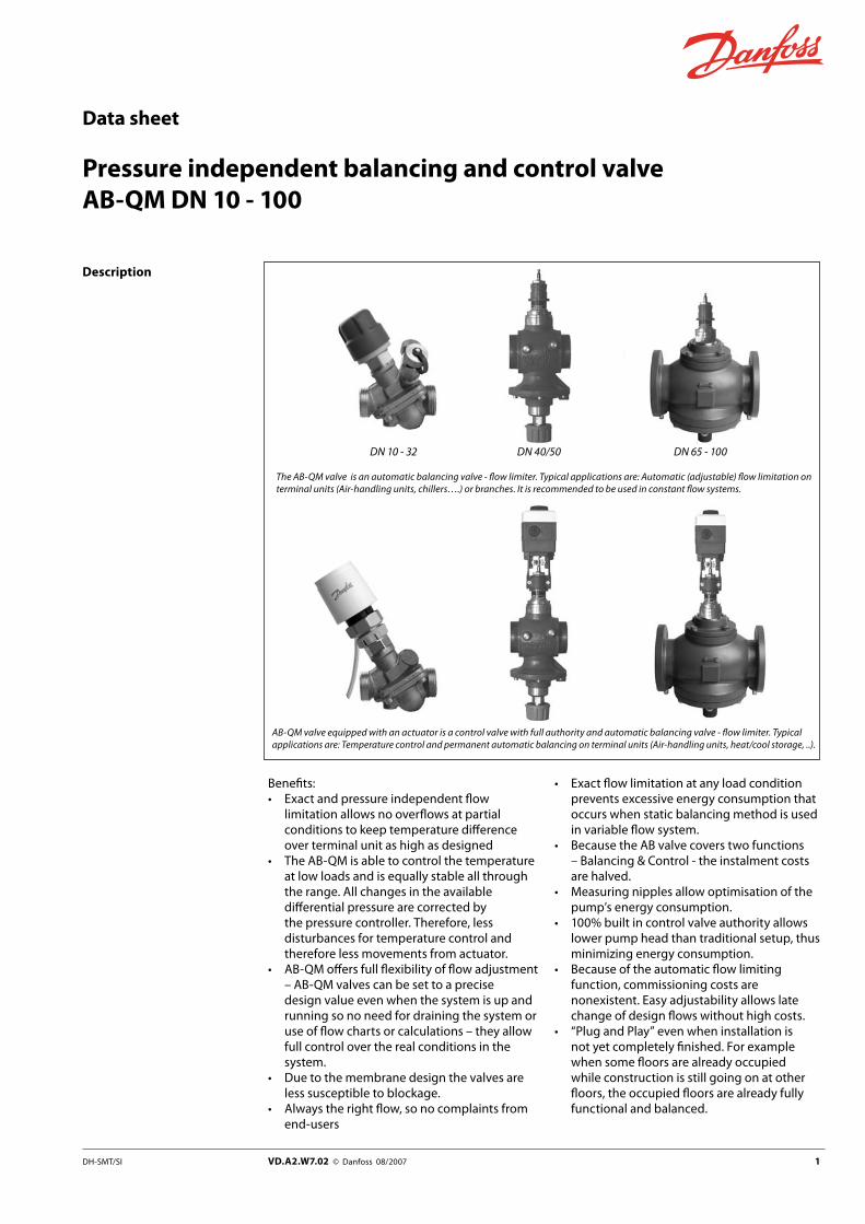
Description
Benefits: • Exact and pressure independent flow
limitation allows no overflows at partial conditions to keep temperature difference over terminal unit as high as designed
• The AB-QM is able to control the temperature at low loads and is equally stable all through the range. All changes in the available differential pressure are corrected by the pressure controller. Therefore, less disturbances for temperature control and therefore less movements from actuator.
• AB-QM offers full flexibility of flow adjustment – AB-QM valves can be set to a precise design value even when the system is up and running so no need for draining the system or use of flow charts or calculations – they allow full control over the real conditions in the system.
• Due to the membrane design the valves are less susceptible to blockage.
• Always the right flow, so no complaints from end-users
• Exact flow limitation at any load condition prevents excessive energy consumption that occurs when static balancing method is used in variable flow system.
• Because the AB valve covers two functions – Balancing & Control - the instalment costs are halved.
• Measuring nipples allow optimisation of the pump’s energy consumption.
• 100% built in control valve authority allows lower pump head than traditional setup, thus minimizing energy consumption.
• Because of the automatic flow limiting function, commissioning costs are nonexistent. Easy adjustability allows late change of design flows without high costs.
• “Plug and Play” even when installation is not yet completely finished. For example when some floors are already occupied while construction is still going on at other floors, the occupied floors are already fully functional and balanced.
The AB-QM valve is an automatic balancing valve - flow limiter. Typical applications are: Automatic (adjustable) flow limitation on terminal units (Air-handling units, chillers….) or branches. It is recommended to be used in constant flow systems.
AB-QM valve equipped with an actuator is a control valve with full authority and automatic balancing valve - flow limiter. Typical applications are: Temperature control and permanent automatic balancing on terminal units (Air-handling units, heat/cool storage, ..).
DN 10 - 32 DN 40/50 DN 65 - 100

2 VD.A2.W7.02 © Danfoss 08/2007 DH-SMT/SI
Data sheet Pressure independent balancing and control valve AB-QM
Description (continuous) Simplifications • Flow limitation is achieved by setting the
valve to required flow - Set & Forget.• Flow is the only parameter to be considered
when designing, so easy and fast valve selection.
• Maximal flow setting of AB-QM corresponds with the maximal flow-speed through that pipe dimension according to international standards.
• Easy trouble shooting• No control ratio calculation• No authority calculation. Commissioning is a
matter of adjusting the valve without using specialised equipment or highly educated staff.
• Compact design allows instalment where only limited space is available, for example in stand alone fan-coil units.
Applications - variable flow systems
Air handling unit (AHU) / fan coil (FCU)
An AB-QM with an actuator can be used as a combined flow limiter and control valve with full authority for an AHU (Air Handling Unit). The AB-QM ensures the required flow on every AHU and simplifies the hydronic balancing of the system. Because of the integrated differential pressure controller the control valve always has 100% authority which means that partial load in the system has no influence on temperature regulation as it will have with normal control valves. By installing AB-QM the whole system
is divided in independent control loop zones not influencing each other. The flow setting is very simple. Just set the required flow for the AHU direct at the AB-QM. There is no special method needed for balancing the whole systems. This means a lot of savings in working hours. Not to forget the combination of several functions in one valve body means less valves and installation work. For temperature control AB-QM can be equipped with different actuators (on/off, 3-point, 0 -10Volt) as required.
Chilled ceiling
AB-QM in systems with chilled ceilings are used to achieve the required flow in the system and to control the temperature. An AB-QM is installed at every chilled ceiling limiting the flow.
The integrated control valve is used for temperature control by mounting an actuator. Different types of actuators can be used.

DH-SMT/SI VD.A2.W7.02 © Danfoss 08/2007 �
Data sheet Pressure independent balancing and control valve AB-QM
Applications - constant flow systems
AB-QM can be used as an automatic flow controller if a system with an AHU/fan coil is run with constant flow (system with 3-way valve). There is no special balancing method needed. The flow can be set directly at the AB-QM.
Alternatively the system can be changed into a system with variable flow because AB-QM is also able to work as a control valve with full authority which means no problems with partial load.
In a one pipe heating system the AB-QM can be installed as an automatic flow controller in every riser. The AB-QM limits the flow to the set value, thus automatically achieving hydronic balance in the system.
There are numerous applications in which AB-QM can be used. In principle every time you need an automatic flow controller or a control valve with full authority it can be used. For example systems with heating/cooling with concrete core activation or small substations.

� VD.A2.W7.02 © Danfoss 08/2007 DH-SMT/SI
Data sheet Pressure independent balancing and control valve AB-QM
Ordering AB-QM
AB-QM DN Qmax.(l/h)
Externalthread Code No. AB-QM External
thread Code No.
10 LF 150G ½ A
00�Z0251G ½ A
00�Z0261
10 275 00�Z0201 00�Z0211
15 LF 275G ¾ A
00�Z0252G ¾ A
00�Z0262
15 450 00�Z0202 00�Z0212
20 900 G 1 A 00�Z020� G 1 A 00�Z021�
25 1.700 G 1 ¼ A 00�Z020� G 1¼ A 00�Z021�
32 3.200 G 1 ½ A 00�Z0205 G 1½ A 00�Z0215
40/50 10.000 G 2 ½ A 00�Z0701
DN Qmax.(l/h)
Flangeconnection Code No.
65 18.000
PN 16
00�Z0702
80 28.000 00�Z070�
100 41.000 00�Z070�AB-QM (DN 10 - 32) can not be upgraded to AB-QM with nipples!
Set-pack (one MSV-M and one AB-QM without nipples)
Type DN Qmax. (l/h) External thread ISO 228/1 Code No.
10 275 G ½ A 00�Z02�1*
15 450 G ¾ A 00�Z02�2
20 900 G 1 A 00�Z02��
25 1.700 G 1¼ A 00�Z02��
32 3.200 G 1½ A 00�Z02�5* Includes MSV-M DN15 with external thread G ¾A
Accessories & spare parts
TypeComments
Code No.To pipe To valve
Union connection(1 pcs.)
R 3/8 DN 10 00�Z02�1
R 1/2 DN 15 00�Z02�2
R 3/4 DN 20 00�Z02��
R 1 DN 25 00�Z02��
R 1 1/4 DN 32 00�Z02�5
R 11/2DN 40/50
00�Z0277
R 2 00�Z0278
Tailpiece welding(1 pcs.)
Weld.
DN 15 00�Z0226
DN 20 00�Z0227
DN 25 00�Z0228
DN 32 00�Z0229
DN 40/5000�Z0275
00�Z0276
Tailpieces for soldering(2 nuts, 2 gaskets,2 soldering nipples
12x1 mm DN 10 065Z7016
15x1 mm DN 15 065Z7017
Locking ring
DN 10 - 32
00�Z02�6
Shut-off & protection piece (max. closing pressure 16 bar) 00�Z02�0
Shut-off - plastic (max. closing pressure 1 bar) 00�Z02�0

DH-SMT/SI VD.A2.W7.02 © Danfoss 08/2007 5
Data sheet Pressure independent balancing and control valve AB-QM
Ordering (continuous)
10.4
±0.
3
Closing point (measure) for DN 10 - DN 32
Combinations AB-QM with electrical actuators
Valve type Stroke(mm)
TWA-Z** ABNM-Z AMV 110NL/AME 110NL AME 15
Recommended ordering code numbers(for details refer to data sheets for these actuators)
082F1226NC, 230 V
082F109�Thermal actuator24 V (0 - 10 V)
082H8056AMV 110 NL/24 V,24 s/mm, 3-point control
082G�028AME15/24 V,11 s/mm, 0 - 10 V
082F1072Adapter for AB-QM(M30 x 1.5)
082H8057AME 110 NL/24 V,24 s/mm, 0 - 10 V
DN 10 - 20 2.25 ü ü ü -
DN 25 - 32 4.50 û* û* ü -
DN 40/50 10 - - - ü
DN 65 - 100 15 - - - ü* up to 60 % of Qmax** Please be aware that only this type of TWA actuator is to be used with AB-QM
Closing pressure for all actuators: 6 bar.
Technical data
Nominal diameter DN 10 Low Flow
10 15 Low Flow
15 20 25 �2 �0/50 65 80 100
Ranges
Qmin (20%)
l/h
30 55 55 90 180 340 640 2.000 - - -
Qmin (40%) - - - - - - - - 7.200 11.200 16.400
Qmax (100%) 150 275 275 450 900 1.700 3.200 10.000 18.000 28.000 41.000
Diff. pressure (p1 - p3) kPa 16 - 400 20 - 400 30 - 400
Pressure stage PN 16
Control range Acc. to standard IEC 534 control range goes to infinity as cv characteristic is linear.
Control valve’s characteristic Linear to be converted by actuator to equal percentage.
Leakage acc. to standard IEC 534 max.0.01 % of kv at 250 N max.0.05 % of kv at 500 N
Flow medium Water and water mixtures with secondary coolants (like glycols)* for closed heating and cooling systems
Water or water mixtures (secondary coolants) closed oxigen tight system
Medium temperature °C −10 ... +120
Stroke mm 2.25 4.5 10 15
Connection
ext. thread (ISO 228/1) G ½” G ½” G ¾” G ¾” G 1” G 1¼” G 1½” G 2” -
flange - PN 16
actuator M30 × 1.5 Danfoss standard
Materials In the water Valve bodies Membranes and O - rings Springs Cone (Pc)Seat (Pc) Cone (Cv)Seat (Cv) Screw Flat gasket Sealing agent (only for valves with measuring nipples)
Brass (CuZn40Pb2 - CW 617N)EPDMW.Nr. 1.4568,W.Nr. 1.4310W.Nr. 1.4305 EPDMCuZn40Pb3 - CW 614NCuZn40Pb2 - CW 617NStainless Steel (A2)NBRDimethacrylate Ester
GG 25
EPDMW.Nr. 1.4568,W.Nr. 1.4310CuZn40Pb3 - CW 614N, W.Nr. 1.4305W.Nr. 1.4305CuZn40Pb3 - CW 614NW.Nr. 1.4305Stainless Steel (A2)NBR
Out of the water Plastic partsInsert parts and outer screws
POMCuZn39Pb3 - CW 614N; W.Nr. 1.4310; W.Nr. 1.4401
* according suitability and usage especially in not oxygen tight systems please mind the instructions given by the coolant producerPc - pressure controller partCv - Control valve part

1
5
6
7
8
2
3
4
Q
P2-P3
P2-P3
Blue
Red
P2-P3
Q=const. Q=const.
Pump optimization
Q
16kP a 400kPa
P1-P3
P1-P3
P1 P2 P3
(20kPa)
6 VD.A2.W7.02 © Danfoss 08/2007 DH-SMT/SI
Data sheet Pressure independent balancing and control valve AB-QM
Design
1 Stuffing box 2 Spindle � Plastic ring � Control valve’s cone 5 Membrane 6 Main spring 7 Hollow cone (pressure
controller) 8 Vulcanized seat (pressure
controller)
1. Differential pressure controller BV The differential pressure controller maintains a constant differential pressure across the control valve.The pressure difference (p2-p3) on the membrane is balanced with the force of the spring. Whenever the differential pressure across the control valve changes (due to a change in available pressure, or movement of the control valve) the hollow cone is displaced to a new position which brings a new equilibrium and therefore keeps the differential pressure at a constant level.
2. Control valve CV The control valve has a linear characteristic. It features a stroke limitation function that allows adjustment of the Kv value. The percentage marked on the scale equals the percentage of 100% flow marked on the pointer. Changing the stroke limitation is done by lifting the blocking mechanism and turning the top of the valve to the desired position, showed on the scale as a percentage. A blocking mechanism automatically prevents unwanted changing of the setting.
Function:The AB-QM valve consists of two parts:1. Differential pressure
controller 2. Control valve

DH-SMT/SI VD.A2.W7.02 © Danfoss 08/2007 7
Data sheet Pressure independent balancing and control valve AB-QM
Sizing Example 1: Variable flow systemGiven: Cool requirement per unit : 1000 W Flow temperature in the system: 6 °CReturn temperature in the system: 12 °C
Required - control and balancing valves: AB-QM and actuators type for BMS system.
Solution: Flow in the system: Q (l/h) Q = 0.86 x 1000 / ( 12-6 ) = 143 l/h
Selected: AB-QM DN 10 mm with Qmax = 275 l/h presetting on 143/275 = 0.52 = 52 % of maximum opening.Actuators: AMV 110NL - 24 V
Remarks: required minimum differential pressure across the AB-QM DN 10 - 16 kPa.
Example 2: Constant flow systemGiven: Cool requirement per unit : 4000 W Flow temperature in the system : 6 °CReturn temperature in the system : 12 °C
Required - automatic flow limiter: AB-QM and presetting.
Solution: Flow in the system : Q (l/h)Q = 0.86 x 4000 / ( 12-6 ) = 573 l/h
Selected: AB-QM DN 20 mm with Qmax = 900 l/h presetting on 573/900 = 0.64 = 64 % of maximum opening.
Remarks: required minimum differential pressure across the AB-QM DN 20 - 16 kPa.
Example �: Sizing AB-QM according pipe dimensionGiven: Flow in system 1.4 m3/h (1400 l/h = 0.38l/s), pipe dimension DN 25 mm
Required - automatic flow limiter: AB-QM and presetting.
Solution: In this case we can selected AB-QM DN 25 mm with Qmax = 1700 l/h
In this case it will be recommended to check the maximum velocity in the pipe. For this we calculate velocity in the pipe for condition: DN 25 mm – Di 27.2 mm
Dimension and condition acceptable, veloscity below 1.0 m/s.
Preseting on the valve AB-QM DN 25 mm 1400/1700 = 0.82 = 82 % of maximum opening.
Remarks: required minimum differential pressure across the AB-QM DN 25 - 20 kPa.
External Flange thread connection

Q
P2-P3
P2-P3
Blue
Red
P2-P3
Q=const. Q=const.
Pump optimization
Q
16kP a 400kPa
P1-P3
P1-P3
P1 P2 P3
(20kPa)
90
60
7080
40
50
(%)
30
20100
90
60
7080
40
50
(%)
30
20100
90
60
7080
40
50
(%)
30
20100
90
60
7080
40
50
(%)
30
20100
Re d
100% 10%
DN 10 - 100 DN 10 - �2
(30 kPa)
(DN 10 - �2)
8 VD.A2.W7.02 © Danfoss 08/2007 DH-SMT/SI
Data sheet Pressure independent balancing and control valve AB-QM
Pump optimising / Trouble shooting
The AB-QM (DN 10-32) features measuring nipples that allow measuring of the pressure difference (p2-p3) across the control valve while AB-QM (DN 40-100) measuring is done between p1 to p3. If the pressure difference exceeds certain value it means the differential pressure controller is operational and the flow limitation is achieved. The measuring function can be used to verify if enough pressure difference is available and thus verify the flow.
It can also be used to optimize the pump head. The pump head can be decreased until no more than the minimal required pressure is available on the most distant valve (in terms of hydronic). This optimal point is to be found when proportionality between pump head and measured differential pressure cease to exist. Verifying the pressure can be done by using a Danfoss PFM 3000 for example (for more details please refer to AB-QM Tech Note).
Presetting The calculated flow can be adjusted easily without using special tools.To change the presetting:- Remove the blue protective cap or the
mounted actuator.- Raise the grey plastic ring and turn to the new
presetting.- Release the white plastic ring and the
presetting is locked.
The presetting scale indicates a values from 100% flow to 0% closed. Counter clock wise turning would increase the flow value while clock wise would decrease it.
When valve is set to 80% or more the red ring (below “DN max flow “ sign) becomes visible.
If the valve is a DN 15 then the max flow = 450 l/h =100% presetting. To set a flow of 270 l/h you have to set: 270/450 = 60%.
Danfoss recomends a presetting/flow from 20% to 100%. Factory presetting is 100%.

DN �0/50 - 100
DH-SMT/SI VD.A2.W7.02 © Danfoss 08/2007 9
Data sheet Pressure independent balancing and control valve AB-QM
Service DN 10 - �2The valve features a service function that allows changing of the “stuffing box (code 065F0006)” under water pressure. Valves are equipped with plastic shut-off mechanism that is to be used for isolating function up to 1 bar differential pressure. When closing against higher differential pressure please use accessory - shut-off & protection piece (003Z0230) or set the value to 0%. Unwanted change of the setting is provided by locking ring (code 003Z0236) which is inserted in the groove below the scale. The locking ring would not allow one to lift the grey plastic ring thus no change of the setting is possible.
Installing AB-QM valve is mono-directional meaning that the valve operates when arrow on the valve body is aligned with flow direction. When this rule is disobeyed the valve acts like variable orifice that cause water hammer at sudden closing when available pressure has increased or valve have been set to lower value.
In case when system condition allows backflows it is strongly recommended to use backflow preventer in order to avoid possible water hammer that can damage the valve as well as other elements in the system.
Presetting (continuous)
DN �0/50 - 100Valves are equipped with manual shut-off for isolating function up to 16 bar .

10 VD.A2.W7.02 © Danfoss 08/2007 DH-SMT/SI
Data sheet Pressure independent balancing and control valve AB-QM
The pressure independent balancing and control valve should be comprised of a linear control valve and an integrated membrane based pressure controller. The valve could be used as an automatic flow limiter.
The valve should have a mechanism to adjust the flow stepless from 100% to 0% (closed) of the maximum flow. The adjustment should be performed without a tool for dimensions up to DN 32 or a standard tool for valves bigger then DN 32. The setting, which can be locked, should be visible from the top for valves DN 32 and smaller and from the side for valves bigger then DN 32.
The control valve stuffing box should be serviceable under pressure for valves up to DN 32 .
The valves should have a shut-off function (positive), separate from the setting mechanism, for valves bigger then DN 32.
The leakage rate should be: max. 0.01% of the kv at 250 N for valves up to DN 32, and for valves up to DN 100 0.05% at 500 N (IEC 543).
The authority of the pressure independent control valve should be 1. Because the control valve should have a linear characteristic, acc. to standard IEC 534 the control ratio will go to infinity.
The maximum flow for every valve dimension should correspond with the VDI 2073 recommendation (the optimum between pump consumption, noise emission and investment in pipes).
Minimum (starting pressure for flow limitation) differential pressure should be 16 kPa for valves up to DN 20, 20 kPa valves up to DN 32 and 30 kPa for valves up to DN 100.
Nominal pressure rating 16 bar, maximal test pressure 25 bar.
Measuring points for pump optimization and flow verification should be available as an option for DN 10-32 and standard for DN 40/50 - 100.
Nominal diameter:
Connection:
Adjustment range from - to m3/h
Produced by: Danfoss
Type: AB-QM
Ordering no.: 003Z02
Tender text

TWA-Z + AB-QM
AMV 110 NL / AME 110 NL + AB-QM
AB-QM DN 10 - 32
AB-QM DN 40/50
AME 15 + AB-QM
DH-SMT/SI VD.A2.W7.02 © Danfoss 08/2007 11
Data sheet Pressure independent balancing and control valve AB-QM
Dimensions
Type L1mm
L2mm
L3mm
H1mm
H2mm
H3mm
H4mm
H5mm
bISO 228/1
Weightkg
AB-QM DN 10 53 36 79 20 73 105 140 - G ½ A 0.38
AB-QM DN 15 65 45 79 25 75 110 145 - G ¾A 0.48
AB-QM DN 20 82 56 79 33 77 115 150 - G 1 A 0.65
AB-QM DN 25 104 71 79 42 88 130 165 - G 1¼ A 1.45
AB-QM DN 32 130 90 79 50 102 145 180 - G 1½ A 2.21
AB-QM DN 40/50 133 - - 174 192 - - 315 G 2½ A 6,87

AB-QM DN 65 - 100
AME 15 + AB-QM
5
12 VD.A2.W7.02 © Danfoss 08/2007 DH-SMT/SI
Data sheet Pressure independent balancing and control valve AB-QM
Type L1mm
H1mm
H2mm
H5mm
b(EN 1092-2)
AB-QM DN 65 290 233 172 373 185
AB-QM DN 80 310 236 177 376 200
AB-QM DN 100 350 249 187 389 220
Dimensions (continuous)