presented by : sanjoy bhattacharjee chief manager (t erminal...
TRANSCRIPT

Presented by :Sanjoy Bhattacharjee
Chief Manager (Terminal Automation)IOCL (MD), HO
Date : 16/01/2014

IntroductionTerminal Automation System
To co ordinate the entire operations of Receipt, Storageand Distribution of Terminals for a virtual unmannedfashion.
The Measurement and Control system needs to takecare of product movement, Reconciliation, Invoicing,Loss and Fraud Prevention, Security Access and Safety.
Consist of various sub systems
2
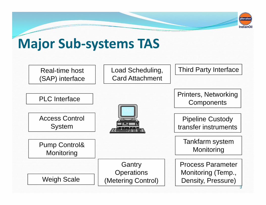
Major Sub-systems TAS
TAS
GantryOperations
(Metering Control)
GantryOperations
(Metering Control)
Pipeline Custodytransfer instruments
Pipeline Custodytransfer instruments
PLC InterfacePLC InterfacePrinters, Networking
ComponentsPrinters, Networking
Components
Access ControlSystem
Access ControlSystem
Real-time host(SAP) interfaceReal-time host(SAP) interface
Load Scheduling,Card AttachmentLoad Scheduling,Card Attachment
Pump Control&Monitoring
Pump Control&Monitoring
Process ParameterMonitoring (Temp.,Density, Pressure)
Process ParameterMonitoring (Temp.,Density, Pressure)Weigh ScaleWeigh Scale
Tankfarm systemMonitoring
Tankfarm systemMonitoring
Third Party InterfaceThird Party Interface
3

Safety + Security Solutions – Tank Farms & Gantry
CCTV Monitoring
Guard House
TruckLoading
bays Parking area
-Tank Gauges & Over fill protection
-Valves Ops from outside Dyke area incl
Emergency Start / Stop PBs, Fire safe Cables
-Point & Open Path HC
-CCTV cameras for process monitoring/
detect spillage
- RIM Seal Fire Detection by Cables
-CCTV for process monitoring /Advanced analytics
to capture oil spillage
- Hydrocarbon Detectors for any spillage
- Safety devices (Overfill, grounding), ESD
Office
Control room
MCC
-Process Control & Safety Control PLC
-TFMS integration with SAP
-HMI/Servers
-CCTV for Process alarms
-Fire Alarm System
Tank farm
WaterTanksAnd Pumps

What makes TAS Different?
5

Why Safety??December 3, 1984: Lethal methyl isocyanate gas leaks from a pesticideplant in Bhopal exposing @5,00,000 people in surrounding community totainted air and water. Confirmed death @4000 immediately after theincident. Govt official declaration in 2006 confirmed 5,58,125 injuries,38,478 partially disabled and @3,900 permanently disabled.
April 26, 1986: Reactor meltdown at Chernobyl nuclear plant in presentday Ukraine. Other than death toll put at 4000 to 9000 by UN,contamination of air, food & water for long periods.
July 6, 1988: Piper Alpha disaster – When the platform blew 167 workersout of 228 were killed off the coast of Aberdeen, in North Seas.
December 11, 2005: Buncefield Storage Terminal – 20 nos. of ProductStorage Tanks with Product destroyed.
October 29, 2009: Fire at IOC’s Jaipur oil terminal.
6

Layers of Protection
7

8

Definition & DifferenceWhat is a safety instrumented system?
Safety systems are designed to respond to conditions of the plant, whichmay be hazardous in themselves or, if no action were taken, couldeventually give rise to a hazard. They must generate the correct outputsto prevent the hazard or mitigate the consequences.
Difference between Process System & Safety Instrumented System: More signal loops would be encountered in SIS due the requirement of
the below: Reliability and availability of Processors, I/Os and associated
components. Monitor Health and loop of I/Os. Partial stroke testing. Logics and Programs developed with blocks defined for Safety
Instrumented Functions. Are normally Discrete I/Os connected to dedicated PLCs.
9
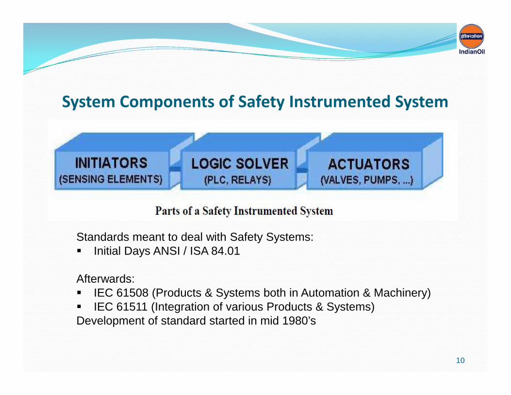
System Components of Safety Instrumented System
Standards meant to deal with Safety Systems: Initial Days ANSI / ISA 84.01
Afterwards: IEC 61508 (Products & Systems both in Automation & Machinery) IEC 61511 (Integration of various Products & Systems)Development of standard started in mid 1980’s
10

Safety Standards for Functional Safety
11

IEC 61508 & 61511
Purpose of IEC 61508:
Basis for those involved in the development of electrical, electronic orprogrammable electronic systems which may have safety implications,
Drafting any other standard where Functional Safety is a relevant factor.
Purpose of IEC 61511:
Gives requirements for the specification, design, installation, operation andmaintenance of a safety instrumented system, so that it can be confidentlyentrusted to place and / or maintain the process in a safe state.
This standard has been developed as a process sector implementation of IEC61508
12
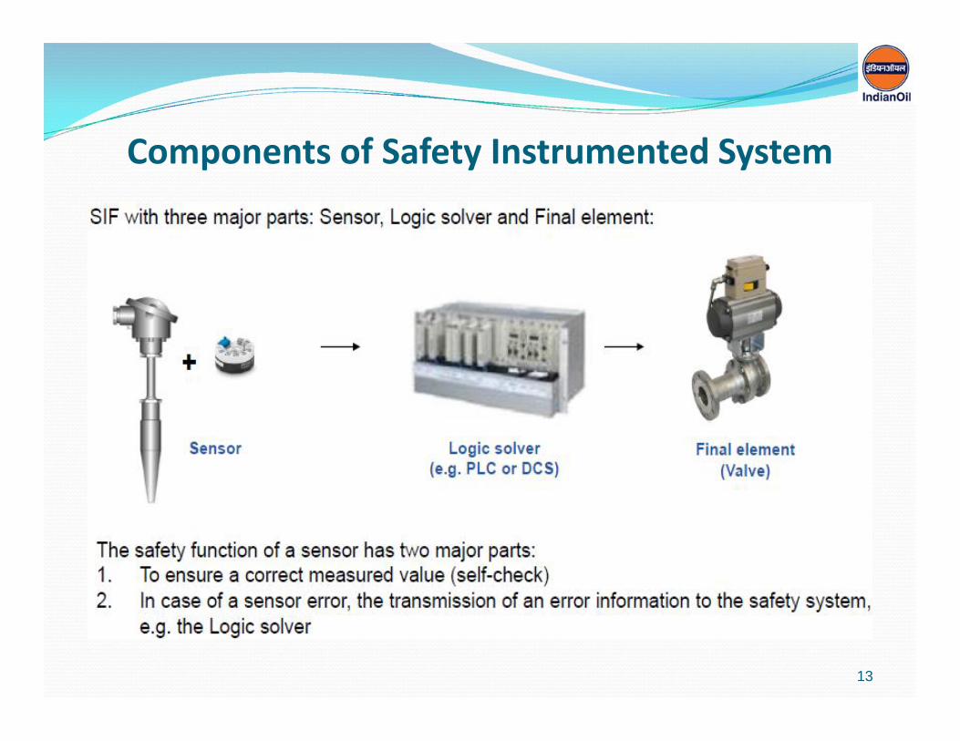
Components of Safety Instrumented System
13
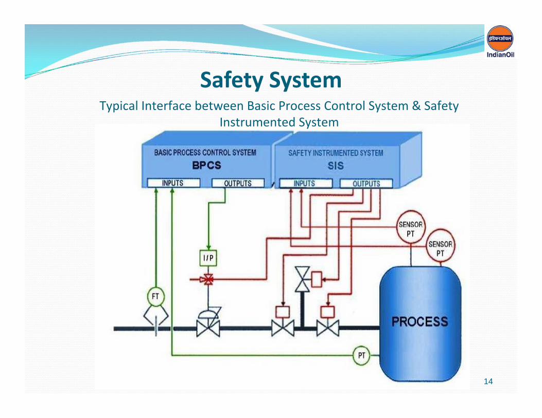
Safety SystemTypical Interface between Basic Process Control System & Safety
Instrumented System
14
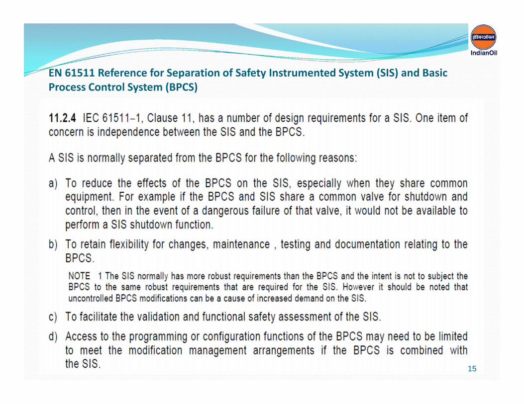
EN 61511 Reference for Separation of Safety Instrumented System (SIS) and BasicProcess Control System (BPCS)
15

Areas of Separation in SIS & BPCS as per EN 61511
16
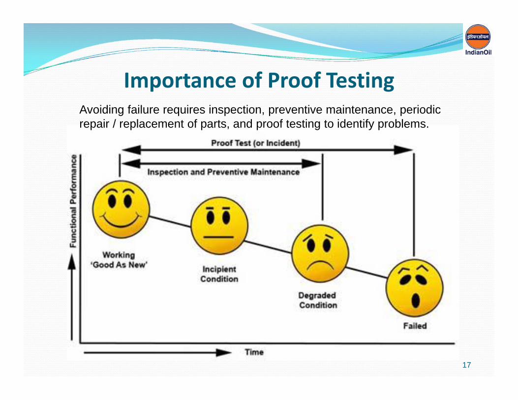
Importance of Proof TestingAvoiding failure requires inspection, preventive maintenance, periodicrepair / replacement of parts, and proof testing to identify problems.
17

What is SIL
SIL stands for SAFETY INTEGRITY LEVEL
18

Terms Used in SIL Classification
19
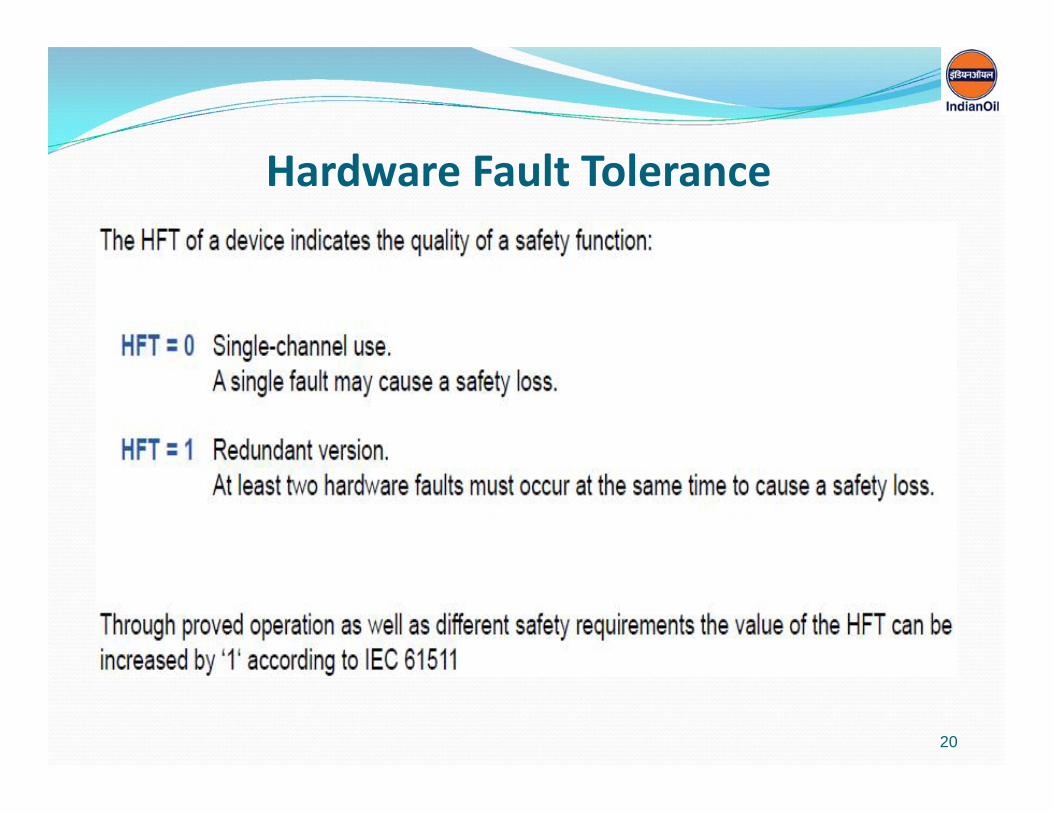
Hardware Fault Tolerance
20

Safe Failure Fraction
21
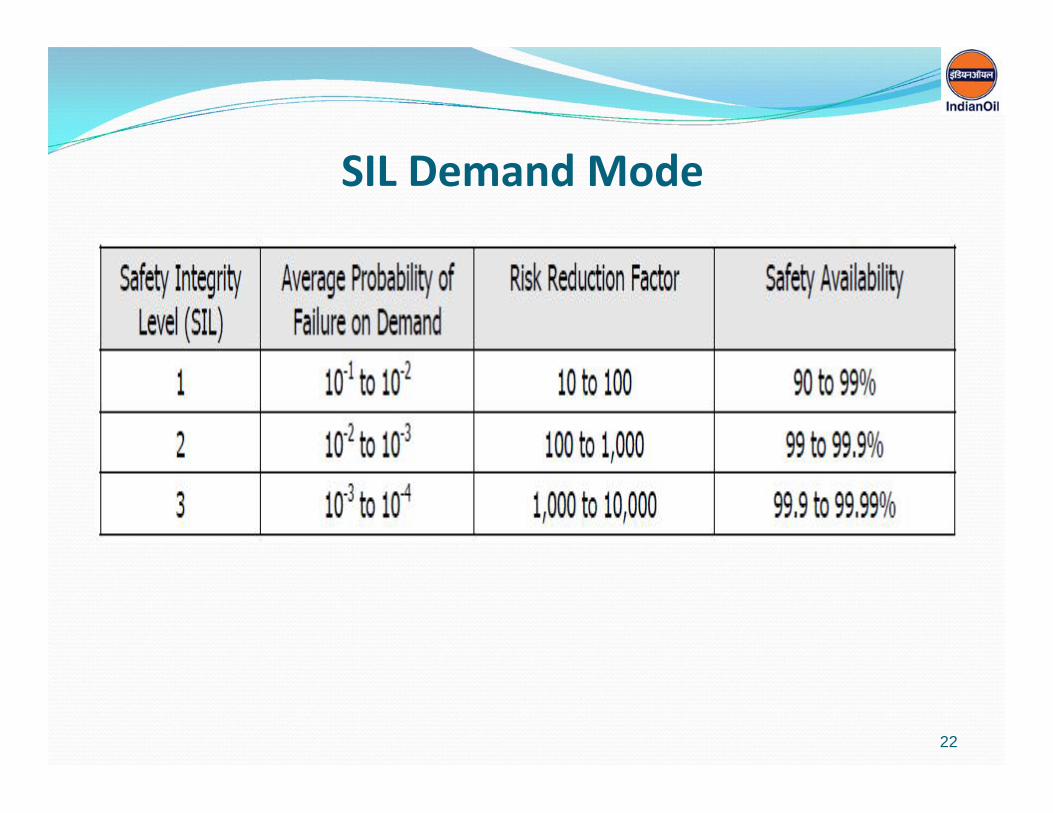
SIL Demand Mode
22

Probability of Failure on Demand
23

SIL Loop Validation
24

Safety System BasicsK. I. S. S
K – KeepI – ItS – SimpleS – Stupid
Acronym design principle noted by U. S. Navy.The KISS principle states that most systems work best if they arekept simple rather than made complex; therefore simplicity shouldbe a key goal in design and unnecessary complexity should beavoided.
25

M B Lal Committee Recommendations
Overview of the Recommendations
30 % to 35 % of the topics deals with Safety in Process & Automation.
Next 40 % to 45 % on SOPs, training, Change Management, PersonnelDeployment.
Rest 20 % to 30 % on other topics.
26

GANTRY AUTOMATION
Loading operation Safety throughEarth RelayOver Spill DetectorLoading Arm Position MonitoringInterlock with ESD / Process PLC for safe shut
down
27

PROCESS PLC
Interface with various stand alone sub systems.
Auto/Manual operations in coordination with TASsystem of all instruments / Sub Systems as explainedArea wise
Manage and handle various Status from the associatedinstruments / Sub Systems
Interlocks and manage functioning of associatedinstruments / Sub Systems.
28

Operations & Interlocks through Process PLC Sub System. Pump Automation.
Pump Sequencing, status monitoring and Auto Operation of ProductPumps
Maintain running hour history Interface with VFD & Soft starter for Auto Operation and Parameter
Monitoring(i.e. Power Consumption, VFD Speed and Status) Pump Interlocks
Pump interlock - example ESD/ Common Fire Alarm is activated. Tank Outlet MOV/DBBV&/ROSOV status not “Open”. Tank level “Lo Lo” Alarm Tank is not in “Dispatch Mode” Fire Water tanks level “Lo Lo” Alarm All fire engine in “Local Mode”
Pump interlock - example Pressure transmitter detects high pressure at Product TLF header. ESD/ Common Fire Alarm activated Tank level “Lo Lo” alarm activated Outlet MOV/DBBV&/ROSOV closed. DCV failure/over filling at respective product loading points. All fire engine put in to “Local Mode”. Fire water tank level “Lo Lo” Alarms. 29

Operations & Interlocks through Process PLC Sub System. Gate Barrier Control System. Access Control Of Tank Truck to only authorized Tank Truck. Opening of Gate Barrier When ESD Pressed.
Header Line Instruments. Pressure Transmitter at Product Header and Pump Discharge Line.
Real Time Pressure monitoring & Trending available on TAS System. Generate HI & LO pressure alarm as configured for interlocked with
Pump automation. Temperature Transmitter at Product Header Line.
Real Time Temperature monitoring & Trending available on TAS System. Density Meter at Product Header Line.
Real Time Standard/Observed Density monitoring & Trending availableon TAS System.
Density Out-of Range Alarm generation & will be annunciation.
30

Operations & Interlocks through Process PLC Sub System. Tank Sequencing & MOV/DBBV Operation.
Tank Sequencing / Mode Selection from TAS HMI & status monitoring Auto Operation of Tank valves , Header Line valves according to Tank
Mode selected from TAS HMI. Live Tank Parameter (Level, Avg. Temp., Ullage, Volume etc)
monitoring and Trending. Interlocks:
Overfill Protection interlock with Receipt valves . Generating Header Line & Pump Discharge Pressure
Interlocks with Header MOV/DBBV. Tank valves Opening and Closing Interlock with Tank Mode
Selection Configuring and interlocking of Various Level Alarms (Level
LO, LOLO,HI,HH,HHH) with Associated Inlet / Outlet valves& Pump Trip.
Water Tank Inventory and Bore-well Pump Automation Auto Operation of Bore-well Pump to maintained Fire Water Level in
Water Tank. Live Water Level and Level Alarm Status Monitoring & Event logging of
Bore-well Pumps.31
Operations & Interlocks through Process PLC Sub System.
Dyke Drain Valve & Water Draw-off Line Flow Switch Position Status Monitoring, Generating Alarm, logging and Annunciation of Alarms.
Additive & Blue Dye Dosing System. Auto Operation of Additive & Blue Dye Dosing. Auto Operation of Additive/Blue Dye Pumps. Generating, logging and interlocking of LOLO Level Alarms with Pump Trip. Live Additive Tank Level monitoring and Trending.
Alarm Annunciation and Hardwired Control Panel. Audio & Visual Annunciation of Critical Alarms. Acknowledgement and Test of Alarm Annunciation. Auto/Manual Mode Selection of valves & Pumps from Hardwired selector
switch. Open & Close of valves with Hardwired Push Buttons. Close command of ROSOV with Hardwired Push Buttons.
32

Emergency Shut Down / Safety PLC
SIL certified PLC.
Maintain Safety of the plant by monitoring status of
critical parameters.
Safe shut down of the plant in case any parameters
behaves as not desired.
Respond to manual ESD pressed and safe shut down of
the plant.
33

Operations & Interlocks through Safety PLC Sub System. Emergency Product Pump / VFD Stop.
Product Pump/VFD Stop when ESD Pressed. TWD Receipt Pump Stop incase of Tank Level Alarm From AOPS of Tank
selected in Receipt Mode.
Gate Barrier Control System. Opening of Gate Barrier When ESD Pressed.
Hydro Carbon Detection System. Real Time LEL Level of Gas Concentration monitoring & Trending available
on TAS System. LEL Level 20% & 60% alarm will be generated, same is interlocked with
Hooters and will be annunciate and Logged in TAS system. Alarm Limits will be configurable in TAS System.
34

Operations & Interlocks through Safety PLC Sub System. ROSOV Operation & Interlocks. Normal Operation
Monitor operation of ROSOV in Local/Remote Mode from Field SelectorSwitch.
Normal Open & Close Operation of ROSOV in Local Mode throughOpen & Close PB Pressed from LCS.
Normal Close Operation of ROSOV in Remote Mode
Operation In case of Emergency. Monitor status of SIL certified relay O/P of Tank Gauges (Primary &
Secondary). Close ROSOV in event of level from Gauges is reaches beyond the
configurable level limits If ROSOV not closed in predefined time than It will be annunciate on
Hooter and ESD will be triggered. On activation of SIL-2 Level Switch (HI-HI-HI) Distress call by
Activating ESD and Alarm & Hooter in Control Room as well as atPipeline Station, ESD Close Command for valves, Stop All pumps.
35
Operations & Interlocks through Safety PLC Sub System.
Fire Detection & Alarm Sub System. The Fire detection & alarm system shall broadly consist of the following: Main control panel (In TAS Control Room) Manual Call Stations. (Break Glass Type) Electronic Hooters Detectors with Fault Isolation Module (Photo Electric / Heat /
Combination) Repeater Panel (at Security Gate & P/L Control Room) Integration with TAS PLC & other systems viz. Existing PA System,
Electric Siren
Fire Alarm interlocks can be configured
36

Operations & Interlocks through Safety PLC Sub System.
Process and Power Emergency Shut Down ESD Push button located in entire terminal at specific key locations Control Room, TM Room, & S&D Room TLF Gantry, TLF/TWD Pump House, Tank Farm System Security Cabin etc…
In event of ESD input detected an alarm will be triggered and startautomatic shut down & tripping of various instruments (i.e. Closing ofROSOV, MOV/DBBV, DCV, tripping of all Pumps and power shut down ofvarious equipments.
HMI will show the location of ESD point in GUI and event will be loggedin the system.
37
Operations & Interlocks through Safety PLC Sub System. Invoking process ESD to ensure the following:
Pop-up Window “EMERGENCY” on all TAS HMI and Logged.
Blowing of wailing siren at the location
Generate ESD in all BCU’s at gantry. All loading operations shall stop instantaneously. Open allmechanized barrier gate for smooth evacuation.
Stop all process VFD, Soft starter, Conventional pumps irrespective of the mode they had beenoperating at.
Close all MOVs (ROSOV&DBB) of on Delivery & Receipt line of the tanks irrespective of mode of theMOV i.e. whether Local or Remote Mode
Closure of all MOVs on TLF header & at custody transfer point.
Send an emergency signal to Pipeline pumping station, so that Pipeline Line Division can immediatelytake shutdown of downstream Booster Pumps for safety of pipeline and tank under receipt.
Recording all TFMS parameters in the system for all the tanks including water tanks.
Hooter annunciation as soon as ESD command is received
System should send an SMS to location in-charge and State Operations Head
38
Operations & Interlocks through Safety PLC Sub System. Invoking Power ESD to ensure the following:
Power ESD should trigger after invoking Process ESD withconfigurable time Delay.
Power ESD should initiate the following Power Shut-down action:
power supply to batch controller will be powered off after the DCV ateach loading point is 100% closed.
Power supply to radar gauges will be powered off. Power supply to MOV power distribution panel shall be tripped after
all MOV’s are closed. Power Supply to MCC tripped. Power supply to barrier gate will be tripped. Power supply to critical load (Control Room, Fire Pump House ,
Three or Four High Mass, Emergency Light, Security Room, MCCRoom Lighting) will not cut-off and remains “ON”
39
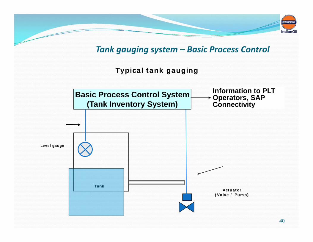
Tank gauging system – Basic Process Control
Tank
Typical tank gauging
Basic Process Control System(Tank Inventory System)
Level gauge
Actuator(Valve / Pump)
Information to PLTOperators, SAPConnectivity
40

Overfill Protection: Tank levels(based on API2350)
Drafted after Buncefield Incident
41

42

Extract from OISD 244
43

Schematic for Overfill ProtectionFIELD
RADARGauge
+
LRC & ProcessControl PLC
andHMI / MMI
SafetyControl
SIL - 3 PLC
TuningFork sw
+
CR FIELD
SIL – 2 H AlarmSwitch
SIL – 2 HH AlarmSwitch
To SAP
1st Tank BodyValve or ROSOV
2nd Tank Body Valve
Independent High Switch
IndependentHH Switch
HH Soft Alarm
Multi Drop permissible
DIRECT Connect
DIRECT Connect
DIRECT Connect
DIRECT Connect
“A” or “B” Class Product TankTo be mounted on Separate Tap off
Other Safety Signals like HCDetectors, Tank Dyke Valve,
Activate Lamps, Hooters, Beacons
Multi Drop permissible
CCTV for Detection of spillage
Actions as per API 2350 3.2.3
ADVANTAGES OF SCHEME• Tuning fork switch will have HHSwitch for Proof Testing
• 1oo2 Voting ensures SIL – 2• Documentation of Proof Testingwith time stamping and record
• Total compliance to Standards
H Alarm
1
12
3
44
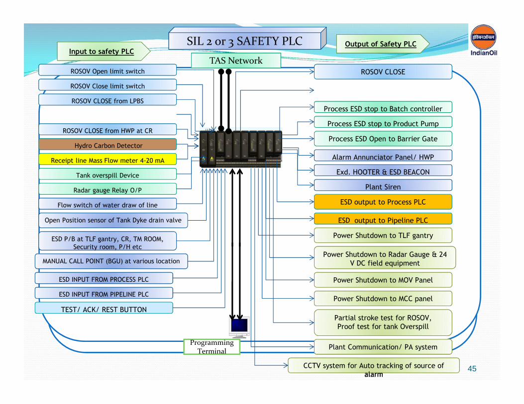
ROSOV Open limit switchROSOV Open limit switch
ROSOV Close limit switchROSOV Close limit switch
Tank overspill DeviceTank overspill Device
Input to safety PLCInput to safety PLC
Radar gauge Relay O/PRadar gauge Relay O/P
Flow switch of water draw of lineFlow switch of water draw of line
Open Position sensor of Tank Dyke drain valveOpen Position sensor of Tank Dyke drain valve
ROSOV CLOSE from LPBSROSOV CLOSE from LPBS
ROSOV CLOSE from HWP at CRROSOV CLOSE from HWP at CR
ESD P/B at TLF gantry, CR, TM ROOM,Security room, P/H etc
ESD P/B at TLF gantry, CR, TM ROOM,Security room, P/H etc
MANUAL CALL POINT (BGU) at various locationMANUAL CALL POINT (BGU) at various location
Output of Safety PLCOutput of Safety PLC
Process ESD stop to Batch controllerProcess ESD stop to Batch controller
ROSOV CLOSEROSOV CLOSE
Process ESD stop to Product PumpProcess ESD stop to Product Pump
Process ESD Open to Barrier GateProcess ESD Open to Barrier Gate
Alarm Annunciator Panel/ HWPAlarm Annunciator Panel/ HWP
Exd. HOOTER & ESD BEACONExd. HOOTER & ESD BEACON
ESD output to Process PLCESD output to Process PLC
Power Shutdown to TLF gantryPower Shutdown to TLF gantry
Power Shutdown to Radar Gauge & 24V DC field equipment
Power Shutdown to Radar Gauge & 24V DC field equipment
Power Shutdown to MOV PanelPower Shutdown to MOV Panel
Power Shutdown to MCC panelPower Shutdown to MCC panel
Plant SirenPlant Siren
ESD output to Pipeline PLCESD output to Pipeline PLC
TAS NetworkTAS Network
SIL 2 or 3 SAFETY PLCSIL 2 or 3 SAFETY PLC
ProgrammingTerminal
Receipt line Mass Flow meter 4-20 mAReceipt line Mass Flow meter 4-20 mA
ESD INPUT FROM PROCESS PLCESD INPUT FROM PROCESS PLC
Partial stroke test for ROSOV,Proof test for tank Overspill
Partial stroke test for ROSOV,Proof test for tank Overspill
Hydro Carbon DetectorHydro Carbon Detector
Plant Communication/ PA systemPlant Communication/ PA system
ESD INPUT FROM PIPELINE PLCESD INPUT FROM PIPELINE PLC
TEST/ ACK/ REST BUTTONTEST/ ACK/ REST BUTTON
CCTV system for Auto tracking of source ofalarm
CCTV system for Auto tracking of source ofalarm
45

Way Forward –
Bridging the gap ?
& The Journey continues…….
46

Thank You
Wish you all a veryHappy, Safe and
Prosperous year 201447