presented at the comsol conference 2008 hannover … · 2009-01-29 · catalysed combustion offers...
TRANSCRIPT

Mathematical Investigation and CFD Mathematical Investigation and CFD Simulation of Monolith Reactors: Simulation of Monolith Reactors: Catalytic Combustion of MethaneCatalytic Combustion of Methane
Maryam GhadrdanMaryam Ghadrdan
Norwegian University of Science Norwegian University of Science and Technology (NTNU)and Technology (NTNU)
Presented at the COMSOL Conference 2008 Hannover

Why microWhy micro--fabrication?fabrication?
The high heat and mass transfer rates possible in microThe high heat and mass transfer rates possible in micro--fluidic fluidic systems allow reactions to be performed under more aggressive systems allow reactions to be performed under more aggressive conditions with higher yields than can be achieved with conditions with higher yields than can be achieved with conventional reactorsconventional reactorsNew reaction pathways deemed too difficult in conventional New reaction pathways deemed too difficult in conventional microscopic equipment, e.g., direct fluorination of aromatic microscopic equipment, e.g., direct fluorination of aromatic compounds (Chambers & Spink, 1999), could be pursued.compounds (Chambers & Spink, 1999), could be pursued.ScaleScale--up to production by replication of microup to production by replication of micro--reactor units used reactor units used in the lab eliminates costly redesign and pilot plant experimentin the lab eliminates costly redesign and pilot plant experiments, s, thereby shortening the development timethereby shortening the development time

Why microWhy micro--fabrication? (contd.)fabrication? (contd.)
The presence of integrated sensor and control units could The presence of integrated sensor and control units could allow the failed reactor to be isolated and replaced while otherallow the failed reactor to be isolated and replaced while otherparallel units continued production.parallel units continued production.These systems are capable of integrating all stages of a These systems are capable of integrating all stages of a complete analysis, including sampling, sample pretreatment, complete analysis, including sampling, sample pretreatment, chemical reaction, separation, detection, and data processing inchemical reaction, separation, detection, and data processing ina highly automated and efficient manner. a highly automated and efficient manner.
Ref: Ref: JakewayJakeway, S. C.; de Mello, A. J.; Russell, E. L., Miniaturized total ana, S. C.; de Mello, A. J.; Russell, E. L., Miniaturized total analysis systems for biological analysis. lysis systems for biological analysis. Fresenius' Journal of Analytical Chemistry Fresenius' Journal of Analytical Chemistry 2000,2000, 366, (6366, (6--7), 5257), 525--539. 539.

What is this problem?What is this problem?
A twoA two--phase (gas & solid) transient catalytic combustor model phase (gas & solid) transient catalytic combustor model using a simplified flow field inside a single channel to test thusing a simplified flow field inside a single channel to test the e advantages of COMSOL Multiphysics software.advantages of COMSOL Multiphysics software.
Ref: Ref: R. E. Hayes and S. T. Kolaczkowski, Introduction to Catalytic Combustion. Amsterdam: Gordon and Breach Science Publ., 1997
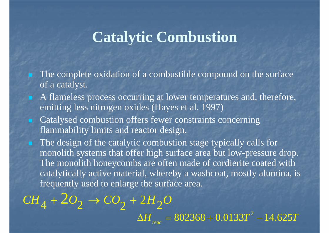
The complete oxidation of a combustible compound on the surfaceof a catalyst. A flameless process occurring at lower temperatures and, therefore, emitting less nitrogen oxides (Hayes et al. 1997) Catalysed combustion offers fewer constraints concerningflammability limits and reactor design. The design of the catalytic combustion stage typically calls formonolith systems that offer high surface area but low-pressure drop. The monolith honeycombs are often made of cordierite coated withcatalytically active material, whereby a washcoat, mostly alumina, is frequently used to enlarge the surface area.
Catalytic Combustion
24 2 222CH O CO H O+ → +2802368 0.0133 14.625reacH T TΔ = + −

Why COMSOL?Why COMSOL?
It has an integrated modeling environment.It has an integrated modeling environment.It takes a semiIt takes a semi--analytic approach: You specify equations, analytic approach: You specify equations, COMSOL symbolically assembles FEM matrices and COMSOL symbolically assembles FEM matrices and organizes the bookkeeping.organizes the bookkeeping.COMSOL is built on top of MATLAB, so user defined COMSOL is built on top of MATLAB, so user defined programming for the modeling, organizing the computation, or programming for the modeling, organizing the computation, or the postthe post--processing has full functionality.processing has full functionality.It provides preIt provides pre--built templates as Application Modes built templates as Application Modes It provides multiIt provides multi--physics modeling linking well known physics modeling linking well known ““application modesapplication modes”” transparently.transparently.COMSOL innovated extended multiCOMSOL innovated extended multi--physicsphysics--coupling coupling between logically distinct domains and models that permits between logically distinct domains and models that permits simultaneous solution.simultaneous solution.
AssumptionsAssumptions
The channel is cylindrical and the flow is axisymmetric and LaminarThe porous medium is homogeneous and isotropicThe interactions between the porous medium and the clear fluid is simulated by the Brinkman formulation [13]The solid matrix and the fluid are assumed to be at local thermal and concentration equilibrium with each other Homogeneous reaction and heat radiation in the bulk phase are ignored.

(1 1 ( )0
u v
z r r
ρ ρ∂ ∂+ =
∂ ∂
(2
( )
( ) 22 .
3
1
u u p uu v V
z r z z z
v ur
r r z r
ρ ρ μ μ
μ
∂ ∂ ∂ ∂ ∂+ = − + − ∇
∂ ∂ ∂ ∂ ∂
∂ ∂ ∂+ +
∂ ∂ ∂
⎡ ⎤⎢ ⎥⎣ ⎦
⎡ ⎤⎢ ⎥⎣ ⎦
(3 ( )( )
22 .
3
2
v v p v uu v
z r z z z r
vV
z r
v v
r r z r
ρ ρ μ
μ μ
μ
∂ ∂ ∂ ∂ ∂ ∂+ = − + +
∂ ∂ ∂ ∂ ∂ ∂
∂ ∂+ − ∇
∂ ∂
∂ ∂+ −
∂ ∂
⎡ ⎤⎢ ⎥⎣ ⎦
⎡ ⎤⎢ ⎥⎣ ⎦
⎡ ⎤⎢ ⎥⎣ ⎦
Mathematical PresentationMathematical Presentation

Mathematical Presentation (contd.)Mathematical Presentation (contd.)
(4, ,( )1
( 1, ..., )
k z k zk k
k k
g
J rJY Yu v W
z r z r r
k K
ρ ρ ω∂ ∂∂ ∂
+ = + +∂ ∂ ∂ ∂
=
⎛ ⎞⎜ ⎟⎝ ⎠
&
(5
1
1
p
K
pk kz kr
k
K
k k k
k
T T p pc u v u v
z r z r
T Tr
z z r r
T Tc J J
z r
h W
ρ
λ λ
ω
=
=
∂ ∂ ∂ ∂+ = +
∂ ∂ ∂ ∂
∂ ∂ ∂ ∂+ +
∂ ∂ ∂ ∂
∂ ∂− +
∂ ∂
−
⎛ ⎞ ⎛ ⎞⎜ ⎟ ⎜ ⎟⎝ ⎠ ⎝ ⎠
⎛ ⎞ ⎛ ⎞⎜ ⎟ ⎜ ⎟⎝ ⎠ ⎝ ⎠
⎛ ⎞⎜ ⎟⎝ ⎠
∑
∑ &

Boundary conditionsBoundary conditionsAt the inlet of the channel:At the inlet of the channel:
Initial values for Velocity, Temperature and ConcentrationInitial values for Velocity, Temperature and Concentration
At the axisymmetric line of the channel:At the axisymmetric line of the channel:Axial symmetry for all parametersAxial symmetry for all parameters
At the outlet of the channel:At the outlet of the channel:Convective flux is assumedConvective flux is assumed
At the wall:At the wall:No slip condition is assumedNo slip condition is assumed

Simulation parameters for the bulk Simulation parameters for the bulk phasephase
Conditions Bulk Phase
Reaction
rate 0
Diffusivity 5 1 .7 59 .9 9 1 0 ( / )1D T P−= × ×
Thermal
conductivity 2 51.679 10 5.073 10k T− −= × + ×
Viscosity 6 87.701 10 4.166 10
12 27.531 10
T
T
− −× + ×
−− ×
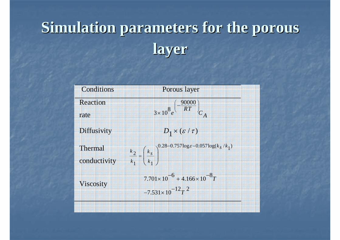
Simulation parameters for the porous Simulation parameters for the porous layerlayer
Conditions Porous layer
Reaction
rate
9000083 10
RTe C A
⎛ ⎞⎜ ⎟⎝ ⎠−
×
Diffusivity ( / )1D ε τ×
Thermal
conductivity
0.28 0.757log 0.057log( / )12
1 1
k ksk k sk k
ε− −
=⎛ ⎞⎜ ⎟⎝ ⎠
Viscosity 6 87.701 10 4.166 10
12 27.531 10
T
T
− −× + ×
−− ×

Simulation conditionsSimulation conditions
Geometrical Conditions Channel length (m) 0.04 Porous layer thickness (mm) 1.0 Catalyst support materials Tortuosity, τ 4 Porosity, ε 0.4 Permeability, K 2m 1×10⁻⁸
Thermal conductivity, ks /W mK 25 Heat capacity, Cps / .J kg K 900
Density, ρs 3/kg m 7870

Temperature Temperature profile along the profile along the
channelchannel

Concentration Concentration profile along the profile along the
channelchannel

Velocity profile in Velocity profile in the bulk phasethe bulk phase

Velocity profile in Velocity profile in the porous layerthe porous layer

Summary of conditions in the Summary of conditions in the simulationssimulations
Case
C0 ( )mol
lit
Tin (K)
Vin ( )m
s
Tout (K)
Nu
1 0.001 700 1 725.1 4.21 2 0.01 700 1 932.1 3.87 3 0.001 800 1 810.6 4.13 4 0.01 800 1 990.2 3.69 5 0.001 700 3 720.5 4.24 6 0.01 700 3 846.5 4.47 7 0.001 800 3 827.3 4.12 8 0.01 800 3 899.2 4.35
Convective heat transferNu
Conductive heat transfer=

Concentration profile for cases 1 (up) Concentration profile for cases 1 (up) and 2 (down)and 2 (down)

Temperature profile for cases 1 (up) and Temperature profile for cases 1 (up) and 4 (down)4 (down)

Velocity profile for cases 1 (up) and 4 Velocity profile for cases 1 (up) and 4 (down)(down)

Thanks for your attentionThanks for your attention