presentazione di powerpoint - eneaold.enea.it/com/web/news/attiv/p_guald/t4_agosteo.pdf ·...
TRANSCRIPT

1
QUADOSQUADOS
Monte Carlo Simulations for the Design of a Hadrontherapy Centre
S. Agosteo1, A. Porta1, L. Ulrici2
1Dipartimento di Ingegneria Nucleare, Politecnico di Milano, via Ponzio 34/3, 20133 Milano, Italy.
2CERN, Geneva 23, Switzerland.

2
QUADOSQUADOS
INTRODUCTION: HADRONTHERAPY
• Hadrontherapy exploits the physical selectivity of charged hadrons for conforming the dose to the target volume:→ protons are used mainly for their ballistic precision;→ in addition light ions can provide superior radiobiological
properties (RBE, OER).

3
QUADOSQUADOS
INTRODUCTION: IMRT VS PROTONS
Between the eyes
Abdomen
Brain
4
QUADOSQUADOS
MONTE CARLO SIMULATIONS
• The MC simulations discussed here refer to:the shielding design (including the maze);the estimate of the radioactivity induced in the materials interacting with the primary beam; the possible activation of the groundwater.
MC simulations were also performed for calculating:the unwanted dose delivered to the patient by secondary radiation;neutron and proton fluence for the estimate of the activation of the air.
• We will refer to the National Centre of Hadrontherapy (CNA) as a practical application.

5
QUADOSQUADOS
THE NATIONAL CENTRE OF HADRONTHERAPY
• The construction of the CNA was financed by the Italian government in 2002.
• The CNA will be built in Pavia and is based on→ a synchrotron capable of accelerating protons and carbon
ions up to 250 MeV and 400 MeV/u, respectively.
Level –2:accelerator bunker
Level –1: Clinic and diagnostic area
Surface building:Offices and patient reception

6
QUADOSQUADOS
THE NATIONAL CENTRE OF HADRONTHERAPY:ACCELERATOR BUNKER (LEVEL –2)
P1=150
δδ
SPOGL.
P8=150
FARMACIAAMBUL.
P11=130
CTRL
DEPOSITI
σ
SALA
CO
NTR
.
DO
SIM
ETRI
A
ττ ρρ
ξξ
P7=220
1919
κ
P9=270
P4=2
00
ψψ2018
AREA DI ATTESA
WC WC
CONTROLLO
INFORM.PRINCIPALE
ω θD
ππ
CAPCAP
SPOGL. SPOGL.
EE
λ
CTRL
SPO
GL.
SPO
GL.
OC
CH
IO
OC
CH
IO
SALA
CO
NTR
.
SPOGL. REC
EPTI
ON
P6=250
P10=100
γ
P3=2
00 γ2121
εε
P5=3
00
ASCAMBIATORI
RAFFREDDAMENTO
SALA DI
α
OFFICINE B
16
13
17
SALA 3
µ
SALA 2
P2'=200ϕ
15
14
17'ν
12
11
TEC
NIC
AA
REA
ββP2=150SALA 1 C
1
2
ALIMENTAZIONI
SORGENTI
8
ι
77
4
χ
3ϖ
9
ο
10
6
5
Power supply system
Treatment rooms Mechanical workshop
Cooling system
Store
Dosimetry room
Synchrotron hall
Main control room
Control room(treat. Room no.1)
Patient positioning
Dressing roomWaiting room
7
QUADOSQUADOS
THE NATIONAL CENTRE OF HADRONTHERAPY:TREATMENT ROOMS
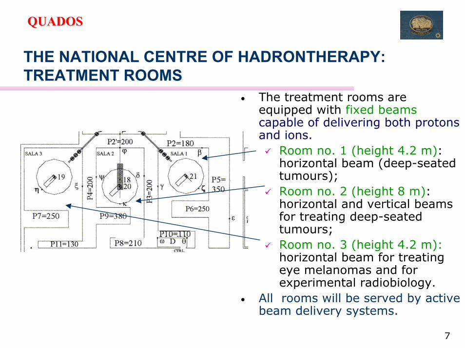
• The treatment rooms are equipped with fixed beamscapable of delivering both protons and ions.
Room no. 1 (height 4.2 m): horizontal beam (deep-seated tumours);Room no. 2 (height 8 m): horizontal and vertical beams for treating deep-seated tumours;Room no. 3 (height 4.2 m): horizontal beam for treating eye melanomas and for experimental radiobiology.
• All rooms will be served by active beam delivery systems.
8
QUADOSQUADOS
SHIELDING DESIGN: GENERAL ASPECTS
• The areas accessible to the personnel during the accelerator operation must be shielded mainly against the secondary radiation generated in the interactions of the primary beam withthe structural materials of the machine and of the beam transport lines.
• The barriers of the treatment rooms should be estimated also considering the patient as a secondary radiation source, since:
the primary beam is completely absorbed in the patient.• Neutrons are the main secondary radiation to be considered for
intermediate energy accelerators devoted to medical applications.

9
QUADOSQUADOS
SHIELDING DESIGN FEATURES
• The shielding design of the CNA was performed for both:250 MeV protons;400 MeV/u carbon ions.
• Although the average beam current delivered to the patient is higher for protons:
1.0 nA (250 MeV protons);0.25 nA (400 MeV/u carbon ions).
→ the yield and energy distribution of secondary neutrons from C ions rule the design of the majority of the shields.
10
QUADOSQUADOS
MC CODES FOR SHIELDING DESIGN
• The generalised Monte Carlo codes applicable for radiation protection calculations, such as FLUKA, MCNPX and MARS do not generally treat secondary particle production from ions withmass larger than one atomic mass unit.
• Development work is under way to implement ion transport in both FLUKA and MARS, but the new versions of the codes have not yet been released;
• In FLUKA ion transport above a few GeV is well advanced and a model to transport ions down to energy of about 50 MeV per nucleon is presently under implementation.
→ Therefore, the simulations for shielding the secondary neutronsfrom C ion beams were performed by using experimental double-differential distributions.

11
QUADOSQUADOS
SHIELDING DESIGN:SOURCES OF SECONDARY NEUTRONS
250 MeV protons on iron
100 100010-1
100
101
Neu
tron
yiel
d (n
eutro
ns p
er im
ping
ing
parti
cle)
Projectile energy (MeV)
carbon ions on Cu 0°-90° (forward 2π)
carbon ions on C 0°-90° (forward 2π)
protons on Fe - (4π) protons on tissue - (4π)
1 10 100 100010-5
10-4
10-3
10-2
10-1
100
400 MeV/u C ions on Cu
Neu
trons
per
prim
ary
ion
(sr-1
MeV
-1)
0° 7.5° 15° 30° 60° 90°
1 10 100 100010-6
1x10⁻⁵
1x10⁻⁴
10-3
10-2
10-1
100
400 MeV/u C ions on C
Neu
trons
per
prim
ary
ion
(sr-1
MeV
-1)
Neutron energy (MeV)
0° 7.5° 15° 30° 60° 90°

12
QUADOSQUADOS
MC SIMULATIONS FOR THE ATTENUATION CURVES
• The double differential TTYs of neutrons generated by 400 MeV/u C ions on Cu and C targets at several angles between 0-90° (Kurosawa et al. Nucl. Sci. Eng. 132 (1999) 30-57) were used as sources for
R=90 m
→ MC simulations with the FLUKA code:• The fluence of outward directed particles was
scored in cosine-weighted boundary x-ings;• Neutrons, photons, secondary protons and
pions were scored;• The H*(10) was estimated with the
conversion factors by Ferrari and Pelliccioni;• Geometry splitting and Russian Roulette
were employed;• R=90 m to minimize curvature effects and the
contribution of scattered neutrons ∝1/(πR2)23 fictitious shells of concrete subdivided into:Polar sectors → angular distribution

13
QUADOSQUADOS
SOURCE TERMS AND ATTENUATION LENGTHS:CLASSICAL FITTING FORMULA
• Usually the attenuation curves of 400 MeV/u carbon ions on carbon and copper are fitted with the classical two-parameter formula for angles up to 50º (40° for 400 MeV/u C ions on lead):
)(g
dexpr
),E(H)/d,,E(H 2
p0p
αλ
−θ
=λθϑ
ϑ
r
θα
d
H = H*(10) beyond the shield;Ep = primary particle energy;θ = angle between the dose scoring direction and beam axis;d = shield thickness;r = distance between the radiation source and scoring position;α = angle between the dose scoring direction and the normal to the shield surface.→ g(α)=1 for the spherical
geometry used in the simulations.
→ otherwise g(α)=cosα
θ

14
QUADOSQUADOS
0 100 200 300 400 500 60010-22
1x10-21
1x10-20
1x10-19
10-18
10-17
1x10-16
0-10 deg.H=H0/r2*exp(-d/lambda)Chi^2 = 7.67864R^2 = 0.99459H0=(8.7898±0.12521)X10-13 Sv m2 per ionlambda=122.9793±0.42556 g cm-2
Tota
l H*(
10) (
Sv p
er c
arbo
n io
n)
Concrete depth (cm)
400 MeV/u C ions on Cu
(0°-10°)
Build-up at low depths
The equilibrium of the neutron spectrum is achieved above 60 cm
SOURCE TERMS AND ATTENUATION LENGTHS:SPECTRUM EQUILIBRIUM
10-3 10-2 10-1 1000.0
1.0x10⁻⁸
2.0x10⁻⁸
3.0x10⁻⁸
4.0x10⁻⁸
5.0x10⁻⁸
6.0x10⁻⁸
7.0x10⁻⁸
400 MeV/u carbon ions on Cu - 0-10 deg.
concrete depth
Φ(E
)*E
(cm
-2 p
er c
arbo
n io
n)
Neutron energy (GeV)
10 cm 20 cm 30 cm 40 cm 60 cm
10-4 10-3 10-2 10-1 1000.0
5.0x10⁻⁹
1.0x10⁻⁸
1.5x10⁻⁸
2.0x10⁻⁸
2.5x10⁻⁸
3.0x10⁻⁸
3.5x10⁻⁸
concrete depth
400 MeV/u carbon ions on Cu - 0-10 deg.
Φ(E
)*E
(cm
-2 p
er c
arbo
n io
n)
Neutron energy (GeV)
60 cm 80 cm 100 cm 120 cm 140 cm 160 cm 180 cm 200 cm
10-4 10-3 10-2 10-1 100
1x10⁻¹⁰
1x10⁻⁹
1x10⁻⁸
1x10⁻⁷
140 cm 160 cm 180 cm 200 cm
400 MeV/u carbon ions on Cu - 0-10 deg.
Φ(E
)*E
(cm
-2 p
er c
arbo
n io
n)
Neutron energy (GeV)
60 cm 80 cm 100 cm 120 cm
10-3 10-2 10-1 10010-10
10-9
10-8
10-7
400 MeV/u carbon ions on Cu - 0-10 deg.
concrete depth
Φ(E
)*E
(cm
-2 p
er c
arbo
n io
n)
Neutron energy (GeV)
10 cm 20 cm 30 cm 40 cm 60 cm

15
QUADOSQUADOS
0 100 200 300 400 500 60010-26
10-25
1x10-24
1x10-23
10-22
1x10-21
1x10-20
1x10-19
10-18
10-17
400 MeV/u C ions on Cu80-90 deg.H=H0/r2*exp(-d/lambda)H0=(1.351±0.028558)X10-15 Sv m2 per ionlambda=97.09322±0.2093 g cm-2To
tal H
*(10
) (Sv
per
car
bon
ion)
Concrete depth (cm)10-7 10-6 1x10⁻⁵ 1x10⁻⁴ 10-3 10-2 10-1 100 101
10-15
1x10-14
1x10-13
1x10-12
1x10-11
1x10⁻¹⁰
1x10⁻⁹
140 cm 160 cm 180 cm 200 cm
80 cm 100 cm 120 cm
400 MeV/u carbon ions on Cu - 80-90 deg.
Φ(E
)*E
(cm
-2 p
er c
arbo
n io
n)Neutron energy (GeV)
20 cm 40 cm 60 cm
400 MeV/u C ions on Cu (80°-90°)
SOURCE TERMS AND ATTENUATION LENGTHS:SPECTRUM EQUILIBRIUM
• No build-up is observed at larger angles and small depths (up to about 60 cm), where the curves decrease with a slope steeper than at equilibrium.

16
QUADOSQUADOS
NEUTRON MEAN ENERGY WITH CONCRETE DEPTH
52.590.6160
90.783.2180
60.090.6140
64.189.6200
55.690.3120
54.696.3100
31.594.580
14.1101.560
32.3100.840
21.3119.820
400 MeV/u C ions on Cu 80-90°400 MeV/u C ions on Cu 0-10°Depth (cm)
Mean Energy (MeV)
At large angles, the lower energy components of the spectrum are attenuated mostly up to about 100 cm concrete depth with a short attenuation length, giving rise to a harder and more penetrating spectral distribution (even if less intense), which is characterised by a larger attenuation length.
The attenuation can be described by double-exponential curves.

17
QUADOSQUADOS
DOUBLE-EXPONENTIAL FITTING FUNCTION
• A double-exponential function was used for fitting the attenuation curves of 400 MeV/u carbon ions on carbon and copper for angles above 50º :
• The second term of this expression describes the attenuation above 60-100 cm and obviously cannot be applied at lower depths, because it would lead to an underestimate of the ambient dose equivalent. In practice, this expression includes the single-exponential functions by setting H0 = H2, λθ = λ 2, θ and setting the first term to zero (i.e., H1 = λ 1, θ= 0).
αλ−
θ+
αλ−
θ=λθ
ϑϑϑ )(g
dexpr
),E(H
)(gdexp
r),E(H
)/d,,E(H,2
2
p2
,12
p1p

18
QUADOSQUADOS
H1,2 AND λ1,2 FOR 400 MeV/u C IONS ON Cu
Angular bin H1(Sv m2 per ion)
λ1(g cm-2)
H2(Sv m2 per ion)
λ2(g cm-2)
0-10° ─ ─ (8.79±0.12)x10-13 122.98±0.43
10-20° ─ ─ (2.13±0.01)x10-13 121.62±0.14
20-30° ─ ─ (8.75±0.06)x10-14 121.21±0.19
30-40° ─ ─ (3.58±0.01)x10-14 122.47±0.15
40-50° ─ ─ (1.93±0.02)x10-14 119.16±0.19
50-60° (1.11±0.13)x10-14 30.93±2.28 (8.10±0.09)x10-15 120.91±0.24
60-70° (7.83±0.56)x10-15 47.47±2.63 (2.91±0.10)x10-15 116.03±2.53
70-80° (6.78±0.51)x10-15 45.61±2.05 (1.88±0.06)x10-15 102.46±0.39
80-90° (7.67±0.29)x10-15 35.88±1.42 (1.30±0.04)x10-15 97.42±0.32

19
QUADOSQUADOS
SOURCE TERMS AND ATTENUATION LENGTHS:FICTITIOUS SHELL APPROXIMATION
• Fluence scoring in each boundary x-ing inside the concrete shell accounted only for outward directedparticles;→ this minimizes the effect
of reflection from the outer shells (especially for neutrons).
• Anyway reflection is not eliminated completely, in this way, because, as a second order effect neutrons can be back-scattered more than once.
nn
n
Prompt γ

20
QUADOSQUADOS
SOURCE TERMS AND ATTENUATION LENGTHS:FICTITIOUS SHELL APPROXIMATION• The effect of the fictitious shell approximation was investigated with separate
simulations considering shells with different thickness for C ions on Cu.
Angular bin Fictitious shell approx. Shells of different thickness
H2 (Sv m2 per ion) λ2 (g cm-2) H2 (Sv m2 per ion) λ2 (g cm-2)
0-10° (8.79±0.12)x10-13 122.98±0.43 (8.15±0.22)x10-13 124.26±0.1010-20° (2.13±0.01)x10-13 121.62±0.14 (2.03±0.03)x10-13 124.76±0.0720-30° (8.75±0.06)x10-14 121.21±0.19 (8.34±0.02)x10-14 122.84±0.0930-40° (3.58±0.01)x10-14 122.47±0.15 (3.82±0.01)x10-14 122.13±0.1240-50° (1.93±0.02)x10-14 119.16±0.19 (1.71±0.01)x10-14 122.29±0.1250-60° (8.23±0.07)x10-15 120.66±0.17 (7.38±0.03)x10-15 121.75±0.1560-70° (3.39±0.06)x10-15 113.85±0.29 (3.23±0.03)x10-15 112.56±0.2670-80° (2.22±0.04)x10-15 100.71±0.22 (2.17±0.02)x10-15 99.02±0.2080-90° (1.35±0.03)x10-15 97.09±0.21 (1.43±0.01)x10-15 94.83±0.13
• The source terms resulted to be slightly lower, as expected.• The difference of the attenuation lengths is lower.
→ The data obtained with the fictitious shell approximation are sufficiently representative of the situation referring to the correct thickness, if the non-statistical uncertainties are taken into account.

21
QUADOSQUADOS
SOURCE TERMS AND ATTENUATION LENGTHS:SECONDARY PARTICLES
• The ratio of the H*(10) due to each secondary particle to the total shows that:
secondary protons are a non negligible fraction of the dose.
0 100 200 300 400 500 60010-7
10-6
1x10⁻⁵
1x10⁻⁴
10-3
10-2
10-1
100
101
400 MeV/u C ions on copper 0-10 degrees
H*(
10) pa
rticl
e/H*(
10) to
tal
Concrete depth (cm)
neutrons photons protons positive pions negative pions
0-10°

22
QUADOSQUADOS
SOURCE TERMS AND ATTENUATION LENGTHS:SECONDARY PARTICLES
Spectral fluence of secondary particles at 1 m depth in concrete.
• Photons are mainly from neutron capture on H;
• Protons are mainly from INC.
10-7 10-6 1x10⁻⁵ 1x10⁻⁴ 10-3 10-2 10-1 1000.0
2.0x10⁻⁹
4.0x10⁻⁹
6.0x10⁻⁹
8.0x10⁻⁹
1.0x10⁻⁸
1.2x10⁻⁸
1.4x10⁻⁸
1.6x10⁻⁸
1.8x10⁻⁸
400 MeV/ucarbon ions on Cu - 0-10 deg.depth in concrete: 100 cm
Φ(E
)*E
(cm
-2 p
er c
arbo
n io
n)
Neutron energy (GeV)10-4 10-3 10-2 10-1 100
0.0
1.0x10⁻⁸
2.0x10⁻⁸
3.0x10⁻⁸
4.0x10⁻⁸
5.0x10⁻⁸
400 MeV/ucarbon ions on Cu0-10 deg.depth in concrete: 100 cm
Φ(E
)*E
(cm
-2 p
er c
arbo
n io
n)
Photon energy (GeV)
10-3 10-2 10-1 1000.0
5.0x10⁻¹³
1.0x10⁻¹²
1.5x10⁻¹²
2.0x10⁻¹²
2.5x10⁻¹²
3.0x10⁻¹²
3.5x10⁻¹²
4.0x10⁻¹²
4.5x10⁻¹²
5.0x10⁻¹²
5.5x10⁻¹²
400 MeV/ucarbon ions on Cu - 0-10 deg.depth in concrete: 100 cm
Φ(E
)*E
(cm
-2 p
er c
arbo
n io
n)
Positive pion energy energy (GeV)10-3 10-2 10-1 100
0.0
5.0x10⁻¹²
1.0x10⁻¹¹
1.5x10⁻¹¹
2.0x10⁻¹¹
2.5x10⁻¹¹
400 MeV/ucarbon ions on Cu - 0-10 deg.depth in concrete: 100 cm
Φ(E
)*E
(cm
-2 p
er c
arbo
n io
n)
Negative pion energy (GeV)
10-4 10-3 10-2 10-1 1000.0
2.0x10⁻¹⁰
4.0x10⁻¹⁰
6.0x10⁻¹⁰
8.0x10⁻¹⁰
1.0x10⁻⁹
1.2x10⁻⁹
400 MeV/ucarbon ions on Cu - 0-10 deg.depth in concrete: 100 cm
Φ(E
)*E
(cm
-2 p
er c
arbo
n io
n)
Proton energy (GeV)
23
QUADOSQUADOS
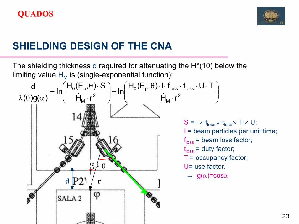
SHIELDING DESIGN OF THE CNA
The shielding thickness d required for attenuating the H*(10) below the limiting value HM is (single-exponential function):
r
θ
d
α
S = I × floss × tloss × T × U;I = beam particles per unit time;floss = beam loss factor;tloss = duty factor;T = occupancy factor;U= use factor.→ g(α)=cosα
⋅
⋅⋅⋅⋅⋅θ=
⋅
⋅θ=
αθλ 2M
losslossp02
M
p0
rHTUtfI),E(H
lnrH
S),E(Hln
)(g)(d
&&

24
QUADOSQUADOS
SHIELDING DESIGN OF THE CNA AN EXAMPLE: switching magnet
⋅
⋅⋅⋅⋅⋅⋅θαθλ=
⋅
⋅θαθλ= 2
M
losslossp02
M
p0
rHTUtWDfI),E(H
ln)(g)(rH
S),E(Hln)(g)(d &&
= 127 cm
r
d
10° <θ < 20°α = 0°Ho = 2.13×10⁻¹³ Sv m2 per ion;ρ = 2.31 g cm-3;λ = 121.62 g cm-2 ; floss = 0.005;tloss = 4 h d-1;T = 1;U= 1;r = 8.89 m;I = 5.19 ×10⁸ part/spill = 5.19 ×10⁸ / 1 (s) x 3600 (s h-1) = 1.87 ×10¹² part h-1;WD = 220 d y-1;HM = 2 mSv y-1.
θ

25
QUADOSQUADOS
ACCESS MAZE TO THE TREATMENT ROOM
• The design is ruled by secondary neutrons produced in the beam delivery system and in the patient.
• The lengths of the access maze of the CNA were estimated with the following expression (Agosteo et al., NIM A 382 (1996) 573-582), resulting from the simulations of mazes of different dimensions:
),w;r(pCrHH k1kk1k lα+ =
+++
++= −−
1rwrtan
1rww
1rrwtan
1r21),w;r(p
2k
2k1
2k
22k
2k1
2k
2k1l
ll
ll
• p1(rk, w,l) is the 2nd coefficient of the Legendre expansion for the solution of the Hubbel integral for a rectangular source.
→ it is related to a diffused rectangular source (the beginning of each maze leg in this case) and a surface-type detector parallel to the source plane.

26
QUADOSQUADOS
ACCESS MAZE TO THE TREATMENT ROOM
r1
r2
r3
H1
H3H2
H4
Hk = H*(10) at the beginning of the k-th leg, k=1,2,3;rk = length of the k-th leg (m);w = width of the maze section (m);l = height of the maze section (m);α<-1, C = parameters obtained by fitting the results of simulations of mazes of different dimensions.

27
QUADOSQUADOS
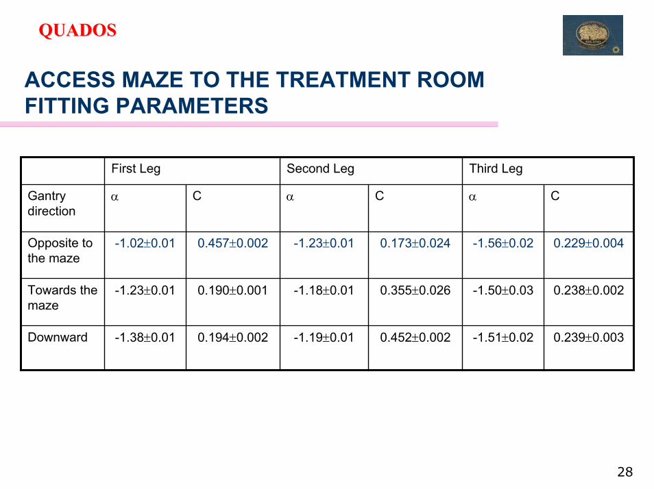
ACCESS MAZE TO THE TREATMENT ROOM: MC SIMULATIONS• The C and α parameters were determined for an isocentric gantry
delivering 250 MeV protons pointing downward and horizontally towards and opposite the maze and rotating in a plane parallel to the maze mouth:→ a passive beam delivery system constituted by a lead scatterer, a
copper collimator and a soft-tissue phantom was considered.• The highest ambient dose equivalent was found for the beam pointing
opposite to the maze.
28
QUADOSQUADOS
ACCESS MAZE TO THE TREATMENT ROOMFITTING PARAMETERS
0.239±0.003-1.51±0.020.452±0.002-1.19±0.010.194±0.002-1.38±0.01Downward
0.238±0.002-1.50±0.030.355±0.026-1.18±0.010.190±0.001-1.23±0.01Towards the maze
0.229±0.004-1.56±0.020.173±0.024-1.23±0.010.457±0.002-1.02±0.01Opposite to the maze
CαCαCαGantry direction
Third LegSecond LegFirst Leg

29
QUADOSQUADOS
ACCESS MAZE TO THE TREATMENT ROOMASSUMPTIONS FOR ION BEAMS
→Since the calculation of a new set of parameters for 400 MeV/u C ions and other beam directions is very time consuming, the following assumptions were made:
the H*(10) at the maze mouth can be roughly estimated by scaling the source terms H0 (for C ions on C) with the distance from the source of beam loss (the patient in this case);
the C and α relating to the beam pointing opposite to the maze mouthwere used, since α gives the lowest attenuation in the first leg;
the energy distribution of neutrons generated from 400 MeV/u C ions on C is different from that relating to 250 MeV protons. Anyway, as stated in [Dinter at al., NIM A 333 (1993) 507-512] and confirmed in [Agosteo et al. NIM A 382 (1996) 573-582], in the second leg of the maze “the spectra of neutrons generated either by high energy protons or by an Am-Be source are similar, extending the validity of the proposed formulas to all accelerators with energies high enough to produced neutrons with energies of a few MeV”.

30
QUADOSQUADOS
ACCESS MAZE TO THE TREATMENT ROOMAN EXAMPLE
r1
r2
r3
H1
H3H2
H4
r
H0
60° <θ < 70°r = 5.3 m;Ho = 4.33×10⁻¹⁵ Sv m2 per ion;w = 2 m;l = 3 mr1 = 2.5 m;r2 = 6 m;r3 = 1.3 m;floss = 1;tloss = 2 h d-1;I = 5.19 ×10⁸ part/spill = 5.19 ×10⁸ / 1 (s) x 3600 (s h-1) = 1.87 ×10¹² part h-1;WD = 220 d y-1;H1 = H0/r2 × I × tloss × floss × WD = 0.13 Sv y-1;H2 = 23.7 mSv y-1;H3 = 0.37 mSv y-1;H4 = 16.4 µSv y-1.

31
QUADOSQUADOS
ESTIMATE OF THE INDUCED ACTIVITY : METHODS
→ The calculation of the induced radioactivity in water can be performed with the following methods:
Track-length method: calculate the track-length fluence of the producing particle in a specified region and fold it with the inelastic cross-sections, integrated over the particle energy;
Residual nuclei method: The residual nuclei scoring in FLUKA can directly give the induced radioactivity in a material. This scoring card is based on the INC model. Residual nuclei are scored when fully de-excited to their ground or isomeric state. Radioactive decay is not treated directly by FLUKA, but can be performed with an off-line code (USRSUW3) provided with the code package;

32
QUADOSQUADOS
ESTIMATE OF THE INDUCED ACTIVITY : METHODS
star density method (high-energy):
• “stars" are defined as inelastic interactions by hadrons of energy larger than 50 MeV;
• The hypothesis of a probable simple proportionality between star density and induced radioactivity is based on the observed constant asymptotic value of the hadron inelastic cross section and on anassumed equilibrium between the fluence of star-producing high-energy hadrons and that of other particles contributing to activation (neutrons below 50 MeV).
• The supposed equilibrium exists only outside thick shielding, but experience has shown that the contribution of low energy particles is generally small compared to that of star-producing hadrons;
• the proportionality factors (omega factors) were established experimentally by measuring the gamma dose rate at the surface of small blocks of material directly irradiated by a proton beam.
*
33
QUADOSQUADOS
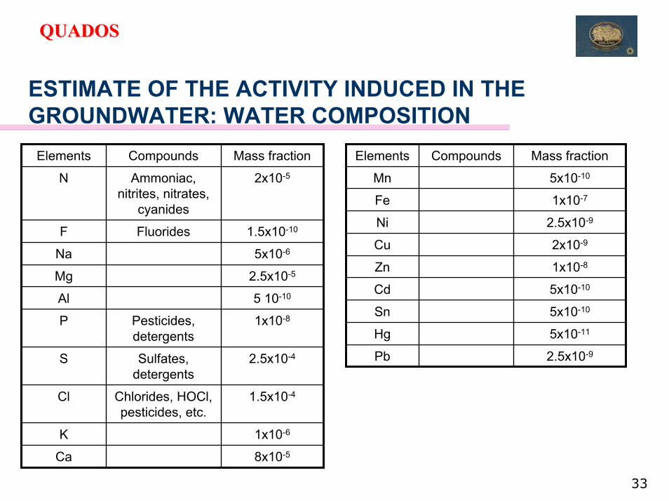
ESTIMATE OF THE ACTIVITY INDUCED IN THE GROUNDWATER: WATER COMPOSITION
8x10⁻⁵Ca
1x10⁻⁶K
1.5x10⁻⁴Chlorides, HOCl, pesticides, etc.
Cl
2.5x10⁻⁴Sulfates, detergents
S
1x10⁻⁸Pesticides, detergents
P
5 10-10Al
2.5x10⁻⁵Mg
5x10⁻⁶Na
1.5x10⁻¹⁰FluoridesF
2x10⁻⁵Ammoniac, nitrites, nitrates,
cyanides
N
Mass fractionCompoundsElements
2.5x10⁻⁹Pb
5x10-11Hg
5x10⁻¹⁰Sn
5x10⁻¹⁰Cd
1x10⁻⁸Zn
2x10⁻⁹Cu
2.5x10⁻⁹Ni
1x10⁻⁷Fe
5x10⁻¹⁰Mn
Mass fractionCompoundsElements

34
QUADOSQUADOS
ESTIMATE OF THE ACTIVITY INDUCED IN THE GROUNDWATER
→Three main points were identified:
the beam directed into the room 3 is pointing towards the external wall. It has been supposed that a consistent reserve of groundwater ispositioned just after the 50 cm thick concrete external wall;
the extraction septa where the probability of beam losses is higher than in the rest of the accelerator;
the beam dumps installed into the synchrotron ring.
• Simulations were performed only for 250 MeV protons.
• Geometry-splitting and Russian-Roulette were used as variance reduction techniques.

35
QUADOSQUADOS
ESTIMATE OF THE ACTIVITY INDUCED IN THE GROUNDWATER: ASSUMPTIONS→ The following assumptions were made:
The groundwater is supposed to be stagnant and positioned just outside the external wall;A cylindrical approximation is used to increase the statistics of the problem and reduce the simulation time;Only the patient is considered in the treatment room (no support for the patient, no other material scattering the beam etc.);No electromagnetic interaction was considered.
Primary proton beam
Target
Concrete
Secondary particles
Ring of water

36
QUADOSQUADOS
ESTIMATE OF THE ACTIVITY INDUCED IN THE GROUNDWATER: IRRADIATION CYCLES
→ The following cases were treated:CASE A (one treatment session): • Irradiation: 3 minutes ON + 17 minutes OFF;• Cycle: 12 h• Decay: 12 h
CASE B (realistic annual operation): • Irradiation: 5 days ON + 2 days OFF;• Cycle: 220 days• Decay: 145 days
CASE C (pessimistic!): • Irradiation: 5 days ON + 2 days OFF;• Cycle: 365 days• Decay: 1day.

37
QUADOSQUADOS
ESTIMATE OF THE ACTIVITY INDUCED IN THE GROUNDWATER: RESULTS FOR THE TREATMENT ROOM
C (conservative)B (annual operation)A (one session)
25.51.13 10-3----64.14 h197Hg
11.49.21 10-411.38.98 10-5--186.1 d195Au
25.01.12 10-425.01.17 10-5--14.10 y113mCd
15.37.73 10-415.33.14 10-50.14.92 10-570.82 d58Co
21.21.92 10-321.22.28 10-4--2.73 y55Fe
11.73.66 10-311.73.52 10-511.71.50 10-535.04 d37Ar
15.33.08 10-315.31.64 10-4--87.51 d35S
21.76.73 10-3--21.76.64 10-514.26 d32P
23.07.07 10-4--23.01.59 10-414.96 h24Na
----26.91.43 10-51.83 h18F
0.95.43 10-30.95.44 10-4--5729 y14C
0.91.730.94.41 10-20.94.67 10-353.29 d7Be
0.61.280.61.35 10-10.61.27 10-412.33 y3H
Uncert.(%)
Specific Activity (Bq l-1)
Uncert.(%)
Specific Activity (Bq l-1)
Uncert.(%)
Specific Activity (Bq l-1)
T1/2Nuclide

38
QUADOSQUADOS
BEAM DUMP ACTIVATION
• Simulations were performed only for 250 MeV protons;
• Activation of the beam dump (in W) was estimated with the RESNUCLE card (FLUKA);
• The contribution of the corrector (upstream) and quadrupole magnet (downstream) was also taken into account.
Beam dumpCorrector
Quadrupole

39
QUADOSQUADOS
BEAM DUMP ACTIVATION: SIMULATION GEOMETRY
• The ellipsoidal shape of the dump cross-section was approximated as the intersection of three ellipses whose parameters were estimated with the MATLAB code.
-80 -60 -40 -20 0 20 40 60 80-80
-60
-40
-20
0
20
40
60
80S UP ERELLIS S E - P rofilo Interno
S emias s e maggiore 70mm
Sem
iass
e m
inor
e 37
mm
S upere llis s e
Dump cross-section
-100 -80 -60 -40 -20 0 20 40 60 80 100-100
-80
-60
-40
-20
0
20
40
60
80
100S UP ERELLIS S E - P rofilo Interno
S emias s e maggiore 70mm
Sem
iass
e m
inor
e 37
mm
Simulation geometry

40
QUADOSQUADOS
BEAM DUMP ACTIVATION
0.27
0.22
0.12
0.22
0.09
0.13
0.09
0.12
Uncert. (%)
1.1131 m174W
1.2735.2 m175W
1.722.5 h176W
1.882.25 h177W
2.3122 d178W
2.4038 m179W
3.51121.2 d181W
1.8675 d185W
Activity [x10-8 Bq]
T1/2Nuclide (Activity>108 Bq)
0.27
0.27
0.17
0.22
0.18
0.11
0.20
0.09
0.12
Uncert. (%)
1.031.37 y173Lu
1.0223.6 h173Hf
1.6870 d175Hf
1.401 h174Ta
1.6410.5 h175Ta
2.048 h176Ta
2.2556.6 h177Ta
2.472.45 h178Ta
2.75665 d179Ta
Activity [x10-8 Bq]
T1/2Nuclide (Activity>108 Bq)
• All nuclides: saturation activity;• Proton intensity= 8.95x10⁹ s-1
• Activation @ beam off

41
QUADOSQUADOS
BEAM DUMP ACTIVATION
• The spectrum of the most probable gamma rays was considered in aMICROSHIELD calculation for estimating the dose equivalent;
• The source volume for MICROSHIELD, i.e. the part of beam dump which may contribute to activation, was estimated with the SRIM code;
• The dose equivalent rate without any shield was estimated to be about 150 µSv h-1 @ 1 m from the dump immediately after the beam is switched off. The activity was considered at saturation for all nuclides.

42
QUADOSQUADOS
BEAM DUMP SHIELDING
1.08
1.77
2.76
4.65
7.94
1500
Dose equivalent rate(µSv h-1) @ 1m (@beam off)
Iron shield thickness (cm)
• The activation of the iron shield (8 cm) contributes to an additional dose equivalent rate of 3.3 µSv h-1 @ 1 m;
• The activation of the corrector (upstream) and quadrupole magnet (downstream) contributes to additional dose rates of 0.2 and 2.85 µSv h-1, respectively ;
• Therefore, the total dose equivalent rate with an iron shield 8 cm thick is 7.35 µSv h-1
@ 1 m from the dump immediately after the beam is switched off.
43
QUADOSQUADOS
CONCLUSIONS
• MC simulations are fundamental for the design of a hadrontherapycentre;
• Data from the literature are fairly scarce for hadrons of intermediate energies, especially for material activation;
• A conservative approach is mandatory when experimental data are not available;
• Parametric formulae are helpful, but the real geometry should besimulated when the design is “frozen”.