presentation 1708 ut1708 auto sd inv acade sds pps
TRANSCRIPT

Join us on Twitter: #AU2013
Automating Substation Design with Autodesk®
Inventor®, Autodesk® AutoCAD® Electrical, and
Substation Design SuiteTerri Humel & Joe WeaverPrincipal Associate Engineers – Nashville Electric Service
This class will help the user prepare for the task of
implementing a model based design solution at an
electrical utility by identifying challenges they may face
along the way, suggesting areas on which to concentrate
customization and training efforts and providing some
examples of how such challenges were dealt with at
Nashville Electric Service.
Class summary
At the end of this class, you will be able to:
Describe the challenges of implementing a model-based substation
design system
Develop a plan to adapt Inventor, AutoCAD Electrical, and Substation
Design Suite for your utility’s specific situation
Automate the Inventor substation design process
Adapt AutoCAD Electrical to specific substation design philosophies and
procedures
Key learning objectives

Speaker Introduction
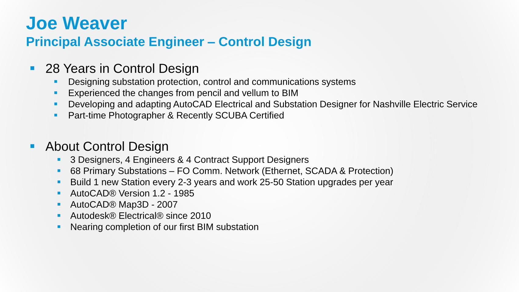
28 Years in Control Design Designing substation protection, control and communications systems
Experienced the changes from pencil and vellum to BIM
Developing and adapting AutoCAD Electrical and Substation Designer for Nashville Electric Service
Part-time Photographer & Recently SCUBA Certified
About Control Design 3 Designers, 4 Engineers & 4 Contract Support Designers
68 Primary Substations – FO Comm. Network (Ethernet, SCADA & Protection)
Build 1 new Station every 2-3 years and work 25-50 Station upgrades per year
AutoCAD® Version 1.2 - 1985
AutoCAD® Map3D - 2007
Autodesk® Electrical® since 2010
Nearing completion of our first BIM substation
Joe WeaverPrincipal Associate Engineer – Control Design

30 Years in Substation Design Designing physical substation layouts including foundations, conduit, grounding and structures
Devised workflows and procedures for designing 3D substations in AutoCAD
Managed the implementation of Inventor & Substation Designer to create intelligent substation models
About Substation Design 3 Designers and 2 Engineers
Purchase power from TVA at 12 feed points
Build 1 new Station every 2-3 years and work 15-25 Station upgrades per year
AutoCAD® Version 1.2 - 1985
AutoCAD® Map3D - 2007
Autodesk® Inventor® since 2008 & Substation Designer Suite since 2010
Terri HumelPrincipal Associate Engineer – Substation Design

Challenges

Began looking at BIM for our design needs in 2007
Identified the needs and potential benefits Faster, more efficient designs
Reduction of human error potential
Standardization and collaboration for consistency in designs
Knowledge capture - Internal and external
Better product for our internal customers
A wealth of data contained in one place
Drawings and reports generated from design data
Tried to identify the challenges we would face
A Little History

Inventor and AutoCAD Electrical aren’t written for Substation Design
This would be “Bleeding Edge” territory
Lots of customization needed
Few available resources for our industry
Perceived benefits
Challenge 1: The Right Tool for The Job

Basic Training was made available but it was very basic
Resources for additional training/consulting were limited
Standard AutoDesk support for in-depth usage were also limited
Found most information in online forums and blogs
Internal training
Challenge 2: Training

Time management
Distractions in both directions
Identifying customization needs
Real world projects vs. “Testing” projects
Requirements of Management
Challenge 3: Learning While Working

Resistance to change
The need for changes to established procedures/standards
Mental shifts – Documentation vs. Modeling
Indecision of Management
Apathy of co-workers/No buy-in
Challenge 4: Other common challenges
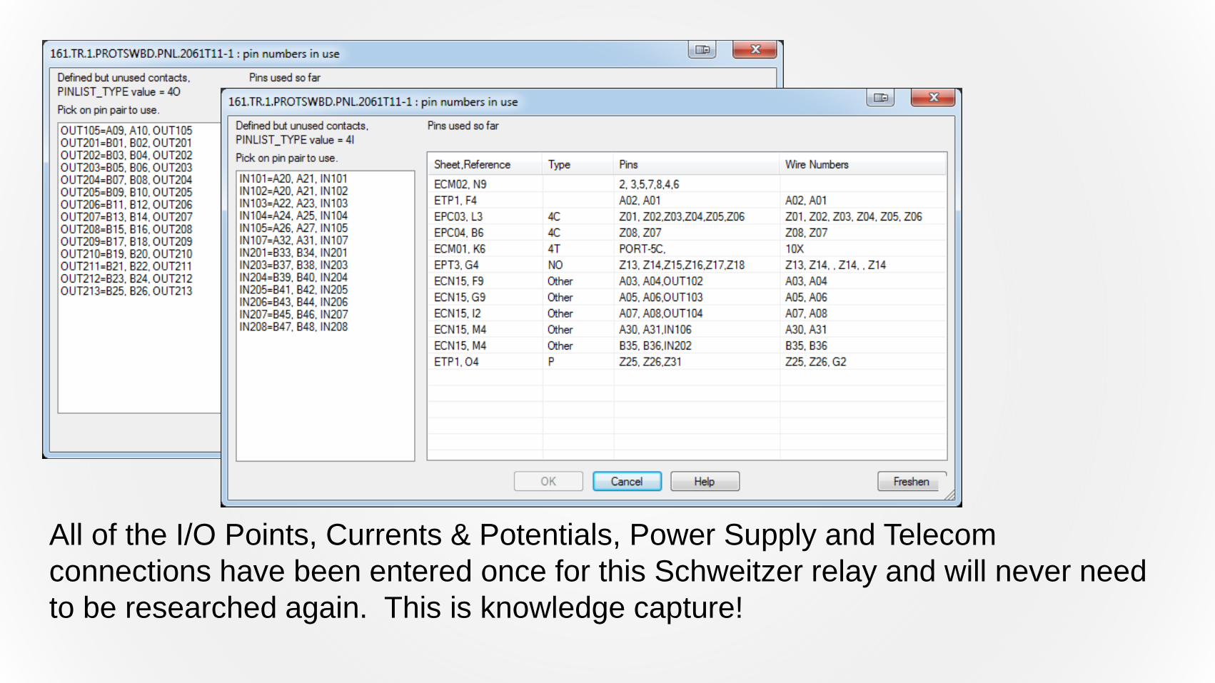
All of the I/O Points, Currents & Potentials, Power Supply and Telecom
connections have been entered once for this Schweitzer relay and will never need
to be researched again. This is knowledge capture!

The Plan

Lot’s of choices to be made
New workflows, procedures and standards
Additional software items (Vault Professional, Substation Design Suite)
Available resources
In the Beginning…

Keep it small – More agile/adaptable
Should have both company/industry knowledge and CAD/Computer skills
Seek input often – Helps with Buy-in
People are more apt to talk to individuals than committees
Step 1: The Core Group

Identify what needs customizing
Determine the level of customization you can live with/without
Consider the working environment – Networked vs. Local
New standards or changes to existing standards
Step 2: Customization

Basic “Look & Feel” Standards
Choose a subset of parts to concentrate on first
Set a defined period of testing and experimentation
Choose a project that minimizes unforeseen or odd circumstances
Give yourself plenty of time to go through the processes of establishing new
standards, procedures or symbols
Step 3: Set Goals

Automate the Inventor Substation Design
Process

Drawing Process


Cabling, Conduit and Grounding
Routed
Systems
Cabling
SDS Cabling
Tube & Pipe Conduit
Fittings and Runs
SDS Conduit Fittings
and Runs
Ground Grid
Ground Lead

Content
A customizable template is included to begin new projects.
The Substation Designer Content Editor provides the ability to use existing
models, fittings, BOM data, etc.
There are also tools for design checks and exporting the BOM.
SDS has several existing Substation models to use as a starting point.
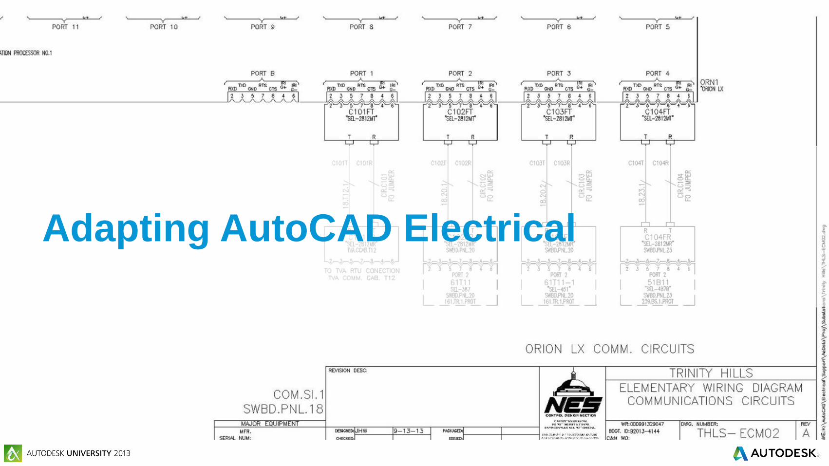
Adapting AutoCAD Electrical
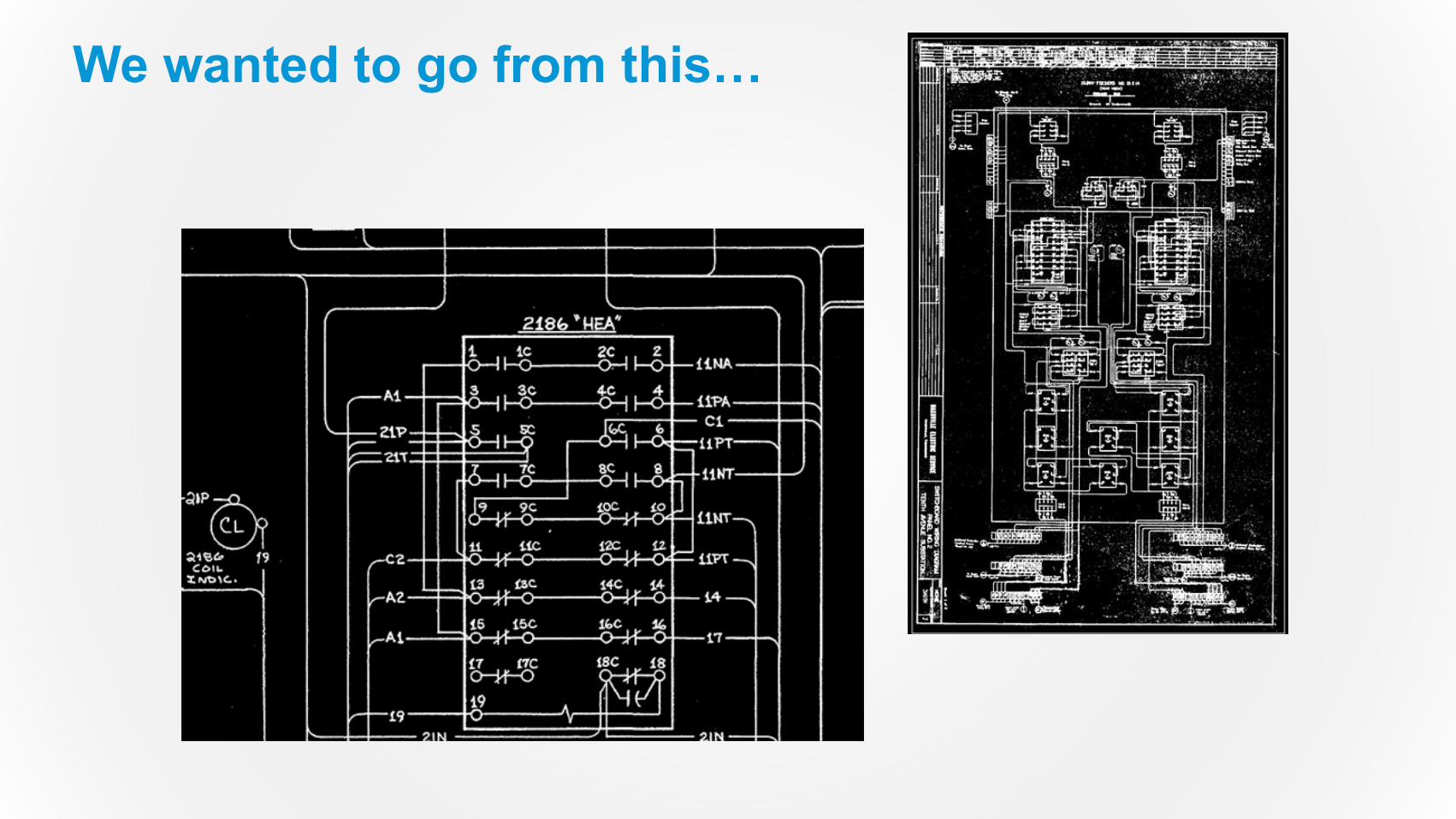
We wanted to go from this…

…To This!

Search Paths & Environment file edits
Network locations and workflow
Wire layers and wire number options
Component name settings and conventions
Ladder & Cross Reference settings
Typical Changes

Wire layer “thickness” to differentiate high voltage busses
One line symbols and layers
Three single phase devices as one symbol on one lines
Layout AND wiring footprints
Terminal block vs terminal strip philosophy
Industry Related Changes

Cable labeling standards and custom cable markers
Adoption of new Test Switch symbols for use with SDS
Standards for Installation & Location Codes
Standards for cross reference methods and symbols
Report layout files and post processing scripts
Wire annotation format standards
Logic and Test Switch planning spreadsheets
Pinlist generation spreadsheet
Company Driven Changes

This spreadsheet is a tool to help generate the rather arcane entries for the pinlist
database. The user picks a pin type from the list and fills out the pin values and any
label information. These are trimmed and concatenated into the strings on the right.

Then all those strings are concatenated together again. Unfortunately these strings
get too large for Excel to concatenate properly, so they get joined in Notepad before
adding to the database.

Cable Fan-in tools
Tie Links
Test Switch Editor
Custom tools
Wire Dot Thickness
Viewport Alignment Tools
SDS Tools by Automation Force

In Conclusion

Training is essential
Choose a team that is both well versed in your company’s standards and
procedures as well as AutoCAD and/or Inventor
Choose your battles
Document everything you do
Our Experience

Autodesk is a registered trademark of Autodesk, Inc., and/or its subsidiaries and/or affiliates in the USA and/or other countries. All other brand names, product names, or trademarks belong to their respective holders. Autodesk reserves the right to alter product and services offerings, and specifications and pricing at any time without notice, and is not responsible for typographical or graphical errors that may appear
in this document. © 2013 Autodesk, Inc. All rights reserved.